Embed Size (px)
Citation preview
7/30/2019 Basic Resistor Circuit
http://slidepdf.com/reader/full/basic-resistor-circuit 1/9
ME 530.241: Electronics and Instrumentation
Lab 1: Basic Resistor Circuits and DC Power
Louis L. Whitcomb and Kyle B. Reed∗
Department of Mechanical Engineering
The Johns Hopkins University
Spring 2009
Welcome to Electronics and Instrumentation, Lab 1. For this course’s laboratory assignments you maywork with up to one partner. Groups of three are not permitted.
Write up your report independently:
• Your lab report should use the attached cover page.
• Lab grading is anonymous. You will receive your personal secret code during the first lab. Peasesubmit you lab reports with your secret student code instead of your name.
• The format of your lab report should parallel this handout: every section number and title should beduplicated in your report, and the results from all labeled items should be included.
• Equations should be written CLEARLY AND COMPLETELY.
• Circuit diagrams and other figures can be hand drawn, but must be neatly included in the document,and carefully labeled and referenced from the text of your writeup.
• †Questions marked with a dagger (
†) can be completed at home; that said, some are worth doing inlab so that you can check to verify that your lab data is reasonable.
• You and your lab partner can share the same lab data that you collected together in lab.
• You should produce your final lab report independently (without your partner).
Working with your colleagues to brainstorm and share problem solving methods is OK. You must workindependently when you do your final write-up, however, without reference to any collective problemsolving session notes — i.e. your final write-up has to come from your brain, your data, your lecturenotes, and your textbook, but not by copying results from group sessions or other sources.
Apparatuses DC power supply (Figure 1(A)), multimeter (Figure 1(B,C)), leads, breadboard (Figure 3).
Components 3 1K-10KΩ resistors, 1K-10KΩ potentiometers.
Overview The purpose of this lab is to learn how to use a breadboard for simple resistor circuits, howto operate a typical DC power supply, and how to use one of the most basic electronics instruments, amultimeter. Before you begin, briefly familiarize yourself with the manuals of the multimeter and DCsupply.
∗ c2009 Noah J. Cowan, Louis L. Whitcomb, and Kyle B. Reed – do not reproduce without permission.
1

7/30/2019 Basic Resistor Circuit
http://slidepdf.com/reader/full/basic-resistor-circuit 2/9
1 Pre-Lab Exercises
Questions from Chapter 1 of [1]
1. 2.5
2. 2.7
3. 2.16
4. 2.17
5. 2.19
6. 2.20
7. 2.29
8. 2.34
9. 2.37
10. 2.59
2
7/30/2019 Basic Resistor Circuit
http://slidepdf.com/reader/full/basic-resistor-circuit 3/9
(A) (B) (C)
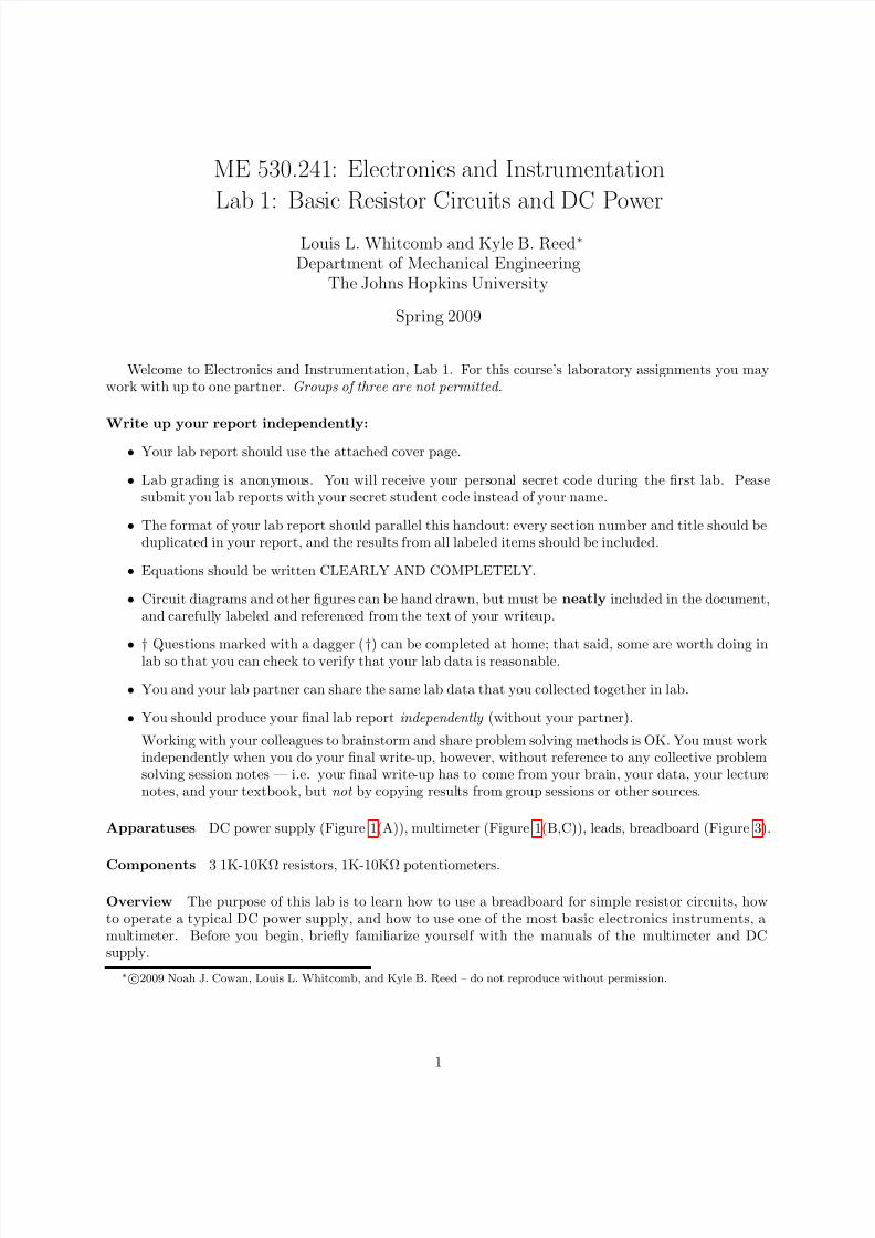
Figure 1: (A) Tektronix PS280 Power Supply. (B) Tektronix DMM254 multimeter and (C) Fluke 170 Seriesmultimeter; please refer to the corresponding manual for details of operation.
2 DC Power Supply and Multimeter
For these questions, set your multimeter to DC volts mode (check the users manual if you are unsure how todo this). Make sure the Tektronix PS280 DC supply is turned off, and that there are no wires hooked up toit. Turn all voltage knobs to zero (completely CCW), and all current knobs to about 9 o’clock on the dial(pointer on knob pointing left).
1. Put the power supply in “Indep.” mode by making sure both tracking control buttons are “out”. (Referto the power supply manual.) Connect the “+/−” (red/black) leads of the multimeter to the “+/−”terminals, respectively, of the rightmost variable output . Now, turn on the power supply. Measure andnote what happens when you do each of the following:
(a) Adjust the voltage knob for the leftmost variable output. What happens and why?
(b) Adjust the voltage knob for the rightmost variable output. What happens and why?
(c) Now adjust either current knob. What happens and why?
(d) Draw a circuit diagram that shows the two variable outputs as voltage sources, and show howthey are interconnected with the multimeter.
2. Return the voltage knobs to the CCW position, and the current knobs to 9 o’clock. Now, put thepower supply in “Parallel” mode by making sure both tracking control buttons are “in”. (Again, lookthis mode up in the manual.) Repeat 1a–1d.
3. Repeat 1a–1d for “Series” mode.
3
7/30/2019 Basic Resistor Circuit
http://slidepdf.com/reader/full/basic-resistor-circuit 4/9
3 Simple Resistor Networks: Series and Parallel
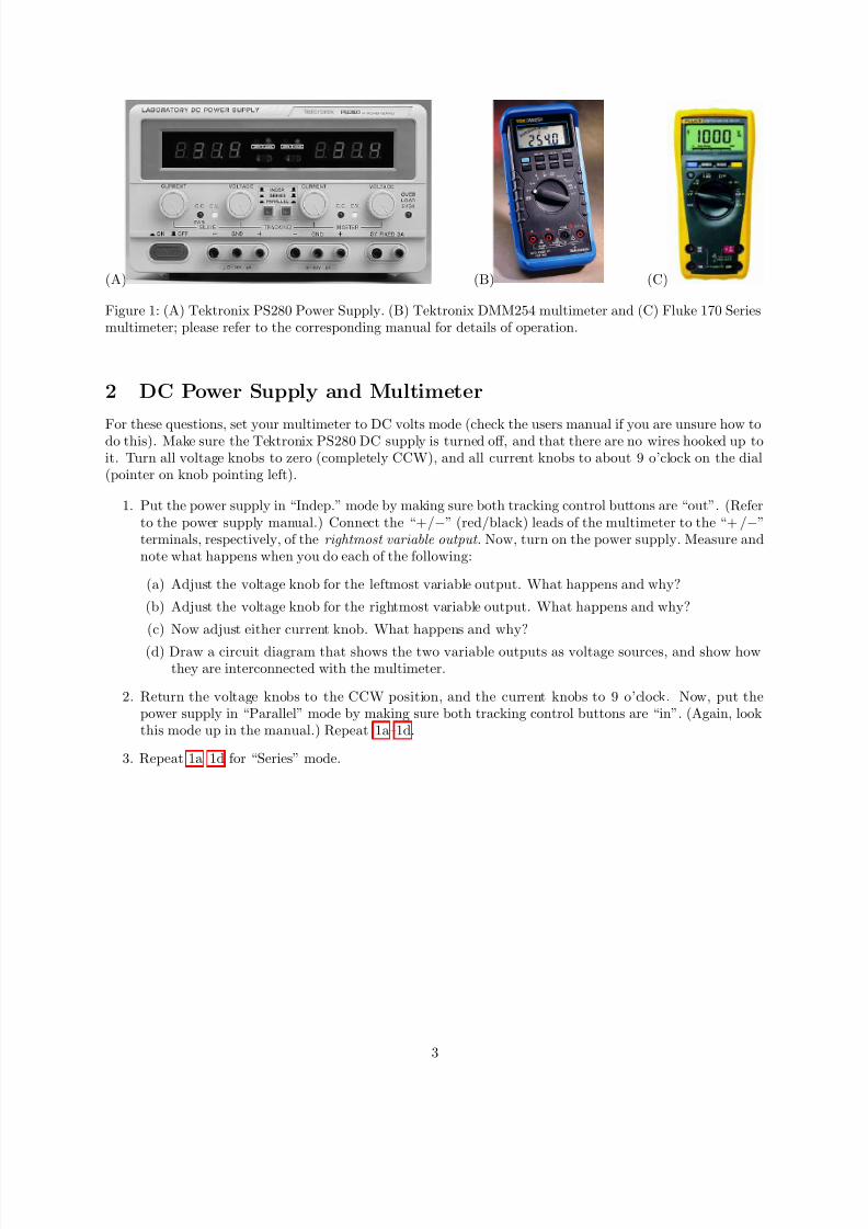
The TA will provide you with three resistors in the 1,000Ω to 10,000Ω range. Resistors are color-coded(Figure 2) to indicate the resistor’s resistance value and precision.
One of the lab partners should hand in the resistors with her/his lab – tape the resistors to the frontpage of the lab. Most of the resistors we will use in this class have a 0.25-watt power rating.
3.1 Reading the Resistor Color Code
Figure 2: Resister color code (from http://dustbunny.physics.indiana.edu/ dzierba/HonorsPhysics).
1. Note for your lab writeup the resistance and precision indicated by the color code of three resistors –call them R1, R2, and R3.
2. Set your multimeter to measure resistance. Your multimeter measures voltage, current, and resistancewith varying accuracy – see the manual. What is the specified accuracy of resistance measurement forthis instrument?
3. Measure and note the resistance of R1, R2, and R3.
4. † Compute and note the error (in percent) between the measured resistance values and the valuesindicated by the color code. Are your resistors within spec?
3.2 Ohm’s Law
All circuits must be built using the breadboard, and you must make neat and tidy breadboard circuits.Where noted, you must have the TA sign off on your breadboard; failure to do so will result in lost points.
Electronics is an art and sloppy work makes for difficult debugging, even for simple circuits!First, turn your PS280 DC Power Supply OFF . Using a banana-to-banana test lead, connect chassis
ground to the negative terminal of one of the variable supplies of the PS280 DC power supply. Use bananaplugs to bring power (“+”) and ground (“−”) to your breadboard terminals, using a thoughtful color choice(e.g. a red lead to the red terminal for “+” and a black lead to the black terminal for “ −”) from this supply.A typical breadboard similar to those in this lab is shown in Figure 3.
Your TA will have an example breadboard set up, and will discuss some best-practices of using bread-boards.
4
7/30/2019 Basic Resistor Circuit
http://slidepdf.com/reader/full/basic-resistor-circuit 5/9
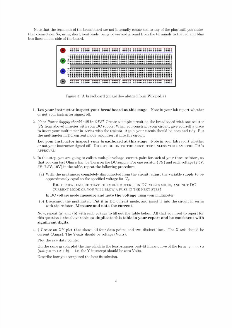
Note that the terminals of the breadboard are not internally connected to any of the pins until you makethat connection. So, using short, neat leads, bring power and ground from the terminals to the red and bluebus lines on one side of the board.
Figure 3: A breadboard (image downloaded from Wikipedia).
1. Let your instructor inspect your breadboard at this stage. Note in your lab report whether
or not your instructor signed off.
2. Your Power Supply should still be OFF! Create a simple circuit on the breadboard with one resistor(R1 from above) in series with your DC supply. When you construct your circuit, give yourself a placeto insert your multimeter in series with the resistor. Again, your circuit should be neat and tidy. Putthe multimeter in DC current mode, and insert it into the circuit.
Let your instructor inspect your breadboard at this stage. Note in your lab report whetheror not your instructor signed off. Do not go on to the next step unless you have the TA’s
approval!
3. In this step, you are going to collect multiple voltage–current pairs for each of your three resistors, sothat you can test Ohm’s law. by Turn on the DC supply. For one resistor ( R1) and each voltage (2.5V,5V, 7.5V, 10V) in the table, repeat the following procedure:
(a) With the multimeter completely disconnected from the circuit, adjust the variable supply to beapproximately equal to the specified voltage for V s.
Right now, ensure that the multimeter is in DC volts mode, and not DC
current mode or you will blow a fuse in the next step!
In DC voltage mode measure and note the voltage using your multimeter.
(b) Disconnect the multimeter. Put it in DC current mode, and insert it into the circuit in serieswith the resistor. Measure and note the current.
Now, repeat (a) and (b) with each voltage to fill out the table below. All that you need to report forthis question is the above table, so duplicate this table in your report and be consistent with
significant digits.
4. † Create an XY plot that shows all four data points and two distinct lines. The X-axis should becurrent (Amps). The Y-axis should be voltage (Volts).
Plot the raw data points.
On the same graph, plot the line which is the least-squares best-fit linear curve of the form y = m ∗ x(not y = m ∗ x + b) — i.e. the Y-intercept should be zero Volts.
Describe how you computed the best fit solution.
5
7/30/2019 Basic Resistor Circuit
http://slidepdf.com/reader/full/basic-resistor-circuit 6/9
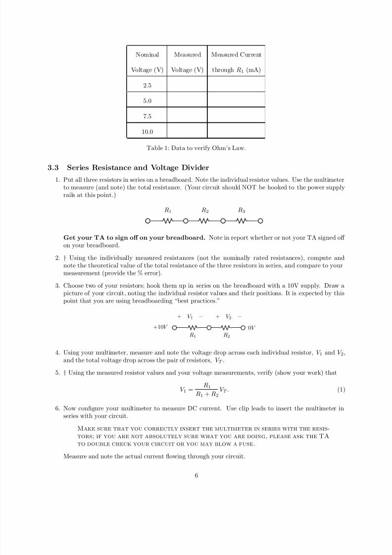
Nominal Measured Measured Current
Voltage (V) Voltage (V) through R1 (mA)
2.5
5.0
7.5
10.0
Table 1: Data to verify Ohm’s Law.
3.3 Series Resistance and Voltage Divider
1. Put all three resistors in series on a breadboard. Note the individual resistor values. Use the multimeterto measure (and note) the total resistance. (Your circuit should NOT be hooked to the power supply
rails at this point.)
R1 R2 R3
Get your TA to sign off on your breadboard. Note in report whether or not your TA signed off on your breadboard.
2. † Using the individually measured resistances (not the nominally rated resistances), compute andnote the theoretical value of the total resistance of the three resistors in series, and compare to yourmeasurement (provide the % error).
3. Choose two of your resistors; hook them up in series on the breadboard with a 10V supply. Draw a
picture of your circuit, noting the individual resistor values and their positions. It is expected by thispoint that you are using breadboarding “best practices.”
+10V
R1 R2
0V
+ V 2 −+ V 1 −
4. Using your multimeter, measure and note the voltage drop across each individual resistor, V 1 and V 2,and the total voltage drop across the pair of resistors, V T .
5. † Using the measured resistor values and your voltage measurements, verify (show your work) that
V 1 =R1
R1 + R2V T . (1)
6. Now configure your multimeter to measure DC current. Use clip leads to insert the multimeter inseries with your circuit.
Make sure that you correctly insert the multimeter in series with the resis-
tors; if you are not absolutely sure what you are doing, please ask the TA
to double check your circuit or you may blow a fuse.
Measure and note the actual current flowing through your circuit.
6
7/30/2019 Basic Resistor Circuit
http://slidepdf.com/reader/full/basic-resistor-circuit 7/9
7. † Using the measured resistor values and your current measurements, verify that
V T = I T (R1 + R2), V 1 = I T R1, and V 2 = I T R2. (2)
Report the % error between the left and right sides of the above three equations.
3.4 Parallel Resistors and Current Divider1. Using the same pair of resistors as in the previous section, hook them up on your breadboard in parallel.
Using your multimeter, measure (and note) the total resistance of the two resistors in parallel.
R1
R2
2. † Compute and note the theoretical value of the total resistance of the two resistors in parallel (basedon measured individual resistance values). Compare this to your actual measurement.
3. Hook your circuit up to a 10V output of your power supply. Measure and note the supply voltageusing the multimeter in DC voltage mode.
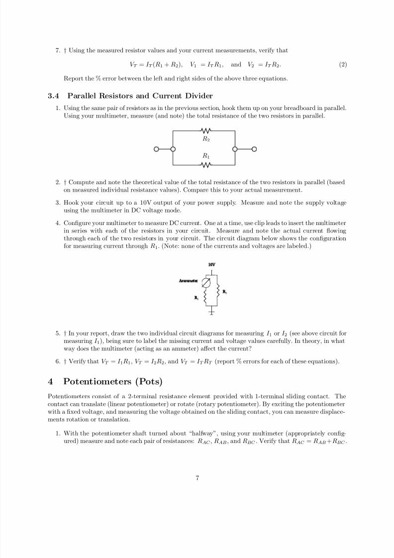
4. Configure your multimeter to measure DC current. One at a time, use clip leads to insert the multimeterin series with each of the resistors in your circuit. Measure and note the actual current flowingthrough each of the two resistors in your circuit. The circuit diagram below shows the configurationfor measuring current through R1. (Note: none of the currents and voltages are labeled.)
5. † In your report, draw the two individual circuit diagrams for measuring I 1 or I 2 (see above circuit formeasuring I 1), being sure to label the missing current and voltage values carefully. In theory, in whatway does the multimeter (acting as an ammeter) affect the current?
6. † Verify that V T = I 1R1, V T = I 2R2, and V T = I T RT (report % errors for each of these equations).
4 Potentiometers (Pots)
Potentiometers consist of a 2-terminal resistance element provided with 1-terminal sliding contact. Thecontact can translate (linear potentiometer) or rotate (rotary potentiometer). By exciting the potentiometerwith a fixed voltage, and measuring the voltage obtained on the sliding contact, you can measure displace-ments rotation or translation.
1. With the potentiometer shaft turned about “halfway”, using your multimeter (appropriately config-ured) measure and note each pair of resistances: RAC , RAB , and RBC . Verify that RAC = RAB+RBC .
7
7/30/2019 Basic Resistor Circuit
http://slidepdf.com/reader/full/basic-resistor-circuit 8/9
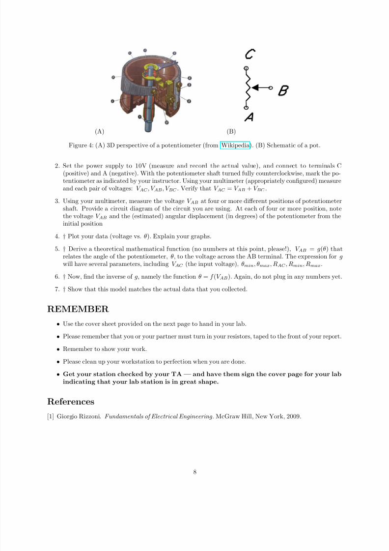
(A) (B)
Figure 4: (A) 3D perspective of a potentiometer (from Wikipedia). (B) Schematic of a pot.
2. Set the power supply to 10V (measure and record the actual value), and connect to terminals C(positive) and A (negative). With the potentiometer shaft turned fully counterclockwise, mark the po-tentiometer as indicated by your instructor. Using your multimeter (appropriately configured) measureand each pair of voltages: V AC , V AB, V BC . Verify that V AC = V AB + V BC .
3. Using your multimeter, measure the voltage V AB at four or more different positions of potentiometershaft. Provide a circuit diagram of the circuit you are using. At each of four or more position, notethe voltage V AB and the (estimated) angular displacement (in degrees) of the potentiometer from theinitial position
4. † Plot your data (voltage vs. θ). Explain your graphs.
5. † Derive a theoretical mathematical function (no numbers at this point, please!), V AB = g(θ) thatrelates the angle of the potentiometer, θ, to the voltage across the AB terminal. The expression for gwill have several parameters, including V AC (the input voltage), θmin, θmax, RAC , Rmin, Rmax.
6. † Now, find the inverse of g, namely the function θ = f (V AB). Again, do not plug in any numbers yet.
7. † Show that this model matches the actual data that you collected.
REMEMBER
• Use the cover sheet provided on the next page to hand in your lab.
• Please remember that you or your partner must turn in your resistors, taped to the front of your report.
• Remember to show your work.
• Please clean up your workstation to perfection when you are done.
• Get your station checked by your TA — and have them sign the cover page for your lab
indicating that your lab station is in great shape.
References
[1] Giorgio Rizzoni. Fundamentals of Electrical Engineering . McGraw Hill, New York, 2009.
8
7/30/2019 Basic Resistor Circuit
http://slidepdf.com/reader/full/basic-resistor-circuit 9/9
ME 530.241 Lab 1: Basic ResistorCircuits and DC Power
My Secret Code :
My Partner’s Secret Code :Lab Date :
Lab Station Number :
Today’s Date :
You must have the T.A. inspect your lab station at the end of your lab session.
T.A. Signature and Date :
9


![Circuit Network Analysis - [Chapter1] Basic Circuit Laws](https://img.pdfslide.us/doc/110x75/55ced242bb61eb192c8b480c/circuit-network-analysis-chapter1-basic-circuit-laws.jpg)