Embed Size (px)
Citation preview
Life Science Journal 2015;12(1s) http://www.lifesciencesite.com
http://www.lifesciencesite.com [email protected] 9
Heat transfer intensifiers efficiency research by numerical methods
Rinat Shaukatovich Misbakhov1, Nikolai Ivanovich Moskalenko1, Victor Mihaylovich Gureev2, Andrey Mihaylovich Ermakov2
1Federal State State-subsidized Educational Instution of Higher Professional Education «Kazan State Power Engineering University», Krasnoselskaya st., 51, Kazan, 420066, Russia
2Federal State Government-Funded Educational Institution of Higher Professional Education Kazan National Research Technical University named after A.N. Tupolev, Marx st., 10, Kazan, 420111, Russia
Abstract. The article presents the results of numerical modeling studies of shell-and-tube heat exchanger with helical, dimple, ring and semiring recesses. We have obtained graphic value dependences of heat transfer coefficients, heat flow, flow structure and pressure loss of the heater in the pipes and annulus of the heat exchanger. Conclusions on the application have been made on various types of intensifiers at different flow of the heater in the shell-and-tube heat exchanger unit. [Misbakhov R.S., Moskalenko N.I., Gureev V.M., Ermakov A.M. Heat transfer intensifiers efficiency research by numerical methods. Life Sci J 2015;12(1s):9-14] (ISSN:1097-8135). http://www.lifesciencesite.com. 3 Keywords: intensifier, heat exchange, modeling, heat transfer, flow structure
Introduction
Enhancement of heat transfer allows more compact heat exchangers or exchangers of more power in the same dimensions, but in the modernization of modern heat exchangers we need to consider the shape and size of intensifiers, as well as the heater flow regimes. Today, application of various intensifiers is widespread, they are used under certain conditions and the heater flow regimes. With the enhancement of heat transfer in shell-and-tube heat exchangers, rounded recesses of various types are used: ring, helical, dimple, etc. Rectangular recesses are used much less frequently, in consequence of a larger hydraulic resistance [1].
The aim of this work is a numerical study of the effect of different heat transfer intensifiers in shell-and-tube heat exchangers, revealing the laws of the various intensifiers depending on flow regimes. According to the analysis of works by Olimpiev V.V., Kalinin E.K., Dreizer G.A., Gortyshov Y.F. and Popov I.A. [2-13], the optimum size have been chosen for the ring, and helical recesses, as well as developed a new type of intensifiers – semiring.
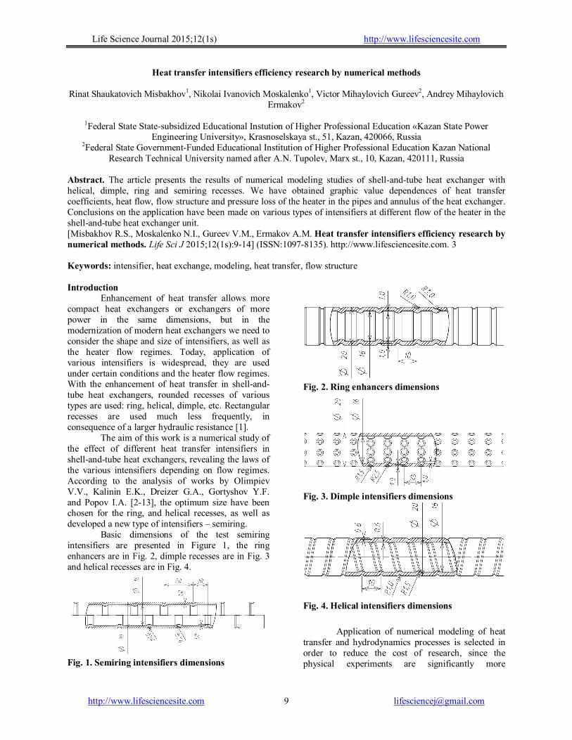
Basic dimensions of the test semiring intensifiers are presented in Figure 1, the ring enhancers are in Fig. 2, dimple recesses are in Fig. 3 and helical recesses are in Fig. 4.
Fig. 1. Semiring intensifiers dimensions
Fig. 2. Ring enhancers dimensions
Fig. 3. Dimple intensifiers dimensions
Fig. 4. Helical intensifiers dimensions
Application of numerical modeling of heat
transfer and hydrodynamics processes is selected in order to reduce the cost of research, since the physical experiments are significantly more
Life Science Journal 2015;12(1s) http://www.lifesciencesite.com
http://www.lifesciencesite.com [email protected] 10
expensive, besides numerical modeling allows to gain an impression of the flow structure, the fields of temperature, pressure and speed rates of the heaters in the heat exchanger. The article uses software package ANSYS CFX (certificate number ANS2011-S015), well-established in the field of numerical modeling. A feature of the present work is that there is a model not only of one heat exchange pipe, but a whole heat exchanger consisting of four pipes that most approximates the model to the real heat exchangers. General part
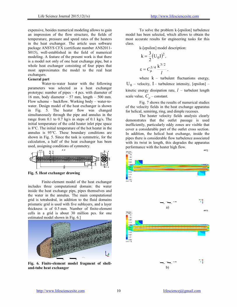
Water-to-water heater with the following parameters was selected as a heat exchanger prototype: number of pipes – 4 pcs. with diameter of 16 mm, body diameter – 57 mm, length – 500 mm. Flow scheme – backflow. Working body – water-to-water. Design model of the heat exchanger is shown in Fig. 5. The heater flow was changed simultaneously through the pipe and annulus in the range from 0.1 to 0.7 kg/s in steps of 0.1 kg/s. The initial temperature of the cold heater inlet pipe space is 8°C. The initial temperature of the hot heater in the annulus is 95°C. These boundary conditions are shown in Fig. 5. Since the task is symmetric, for the calculation, a half of the heat exchanger has been used, assigning conditions of symmetry.
Fig. 5. Heat exchanger drawing
Finite-element model of the heat exchanger includes three computational domain: the water inside the heat exchange pips, pipes themselves and the water in the annulus. The main computational grid is tetrahedral, in addition to the fluid domains prismatic grid is used with five sublayers, and a layer thickness is of 0.5 mm. Number of finite-element cells in a grid is about 30 million pcs. for one estimated model shown in Fig. 6.]
Fig. 6. Finite-element model fragment of shell-and-tube heat exchanger
To solve the problem k-[epsilon] turbulence model has been selected, which allows to obtain the most accurate results for engineering tasks for this class.
k-[epsilon] model description:
20IU2
3k ,
l
2/34/3 k
C ,
where k – turbulent fluctuations energy,
0U – velocity, I – turbulence intensity, [epsilon] –
kinetic energy dissipation rate, l – turbulent length
scale value, C – constant.
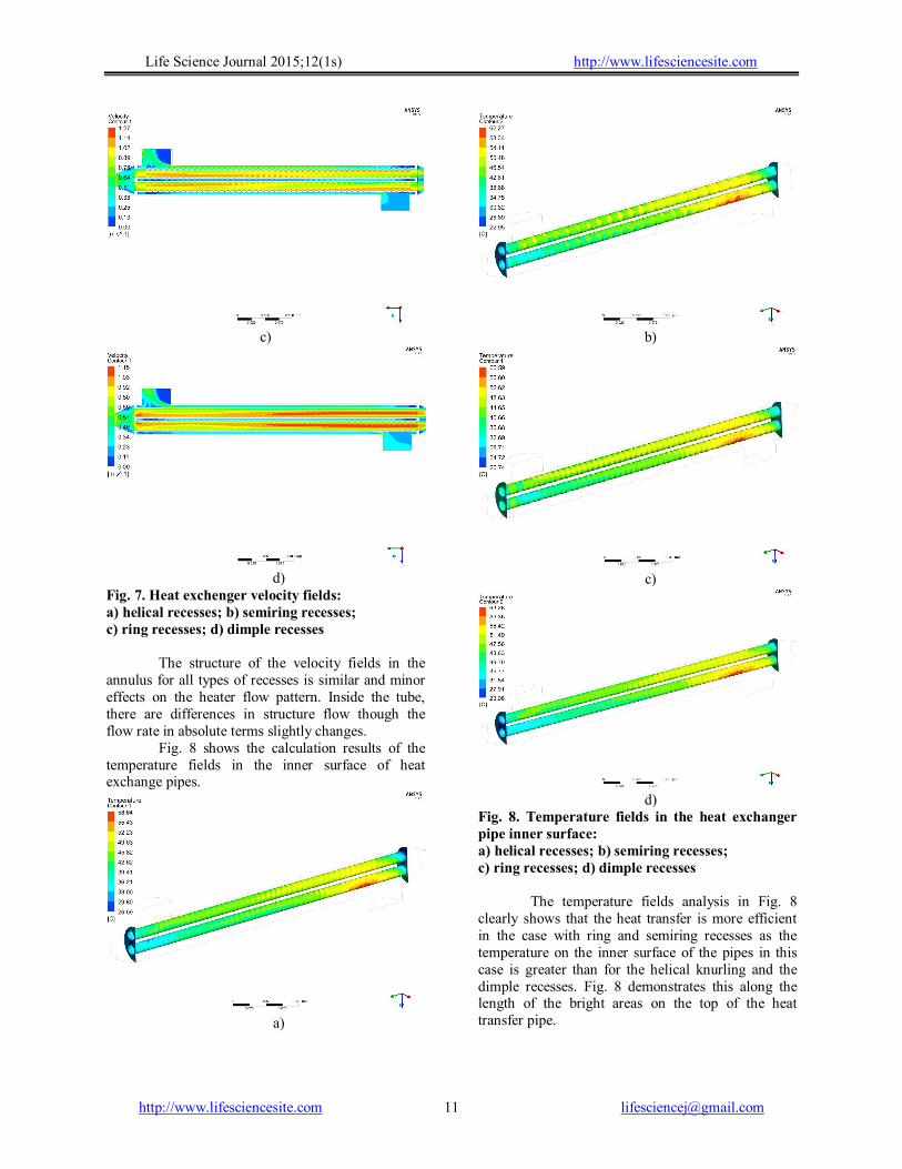
Fig. 7 shows the results of numerical studies of the velocity fields in the heat exchange apparatus for helical, semiring, ring, and dimple recesses.
The heater velocity fields analysis clearly demonstrates that the outlet passage is used inefficiently, particularly eddy zones are visible that cover a considerable part of the outlet cross section. In addition, the helical heat exchange, inside the pipes there is considerable flow turbulence associated with its twist in length, this degrades the apparatus performance with the heater high flow.
a)
b)
Life Science Journal 2015;12(1s) http://www.lifesciencesite.com
http://www.lifesciencesite.com [email protected] 11
c)
d)
Fig. 7. Heat exchenger velocity fields: a) helical recesses; b) semiring recesses; c) ring recesses; d) dimple recesses
The structure of the velocity fields in the annulus for all types of recesses is similar and minor effects on the heater flow pattern. Inside the tube, there are differences in structure flow though the flow rate in absolute terms slightly changes.
Fig. 8 shows the calculation results of the temperature fields in the inner surface of heat exchange pipes.
а)
b)
c)
d)
Fig. 8. Temperature fields in the heat exchanger pipe inner surface: a) helical recesses; b) semiring recesses; c) ring recesses; d) dimple recesses
The temperature fields analysis in Fig. 8 clearly shows that the heat transfer is more efficient in the case with ring and semiring recesses as the temperature on the inner surface of the pipes in this case is greater than for the helical knurling and the dimple recesses. Fig. 8 demonstrates this along the length of the bright areas on the top of the heat transfer pipe.
Life Science Journal 2015;12(1s) http://www.lifesciencesite.com
http://www.lifesciencesite.com [email protected] 12
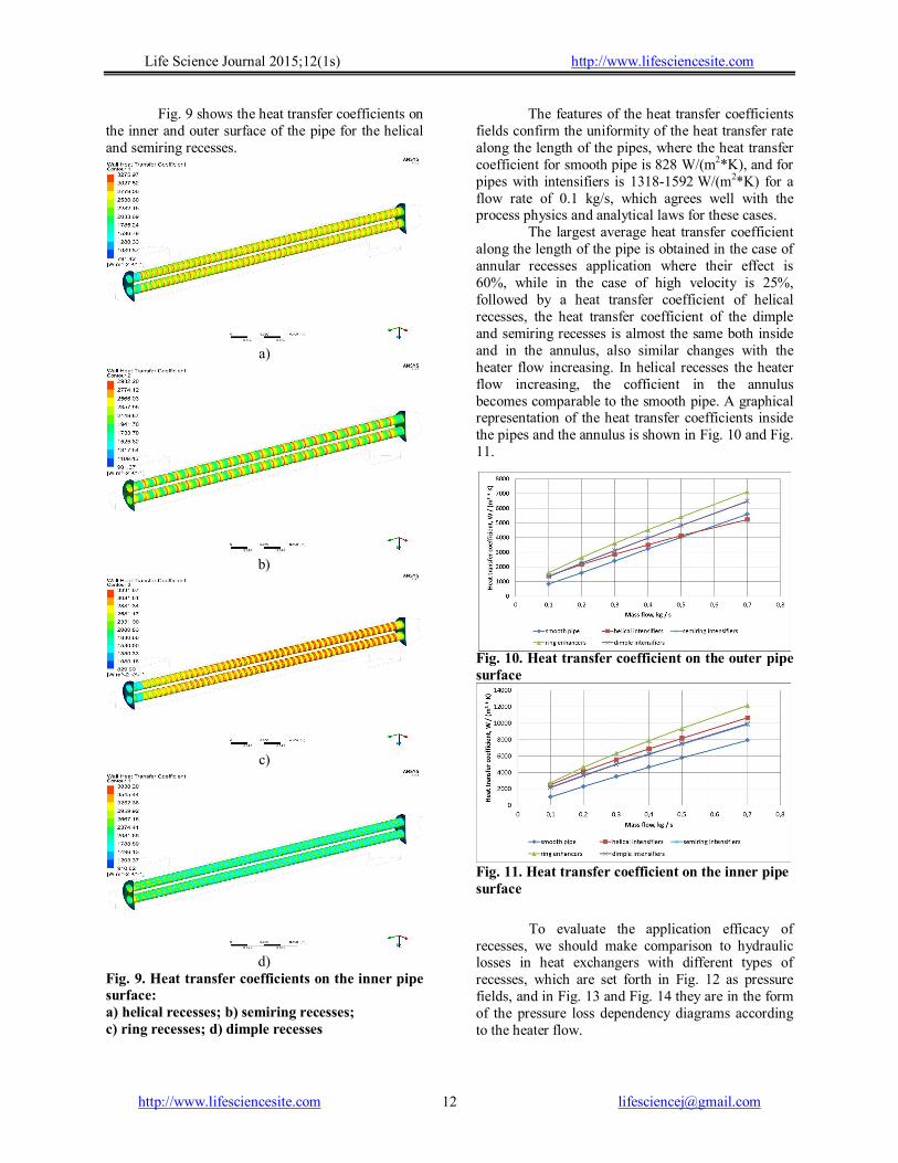
Fig. 9 shows the heat transfer coefficients on the inner and outer surface of the pipe for the helical and semiring recesses.
а)
b)
c)
d)
Fig. 9. Heat transfer coefficients on the inner pipe surface: a) helical recesses; b) semiring recesses; c) ring recesses; d) dimple recesses
The features of the heat transfer coefficients fields confirm the uniformity of the heat transfer rate along the length of the pipes, where the heat transfer coefficient for smooth pipe is 828 W/(m2*K), and for pipes with intensifiers is 1318-1592 W/(m2*K) for a flow rate of 0.1 kg/s, which agrees well with the process physics and analytical laws for these cases.
The largest average heat transfer coefficient along the length of the pipe is obtained in the case of annular recesses application where their effect is 60%, while in the case of high velocity is 25%, followed by a heat transfer coefficient of helical recesses, the heat transfer coefficient of the dimple and semiring recesses is almost the same both inside and in the annulus, also similar changes with the heater flow increasing. In helical recesses the heater flow increasing, the cofficient in the annulus becomes comparable to the smooth pipe. A graphical representation of the heat transfer coefficients inside the pipes and the annulus is shown in Fig. 10 and Fig. 11.
Fig. 10. Heat transfer coefficient on the outer pipe surface
Fig. 11. Heat transfer coefficient on the inner pipe surface
To evaluate the application efficacy of recesses, we should make comparison to hydraulic losses in heat exchangers with different types of recesses, which are set forth in Fig. 12 as pressure fields, and in Fig. 13 and Fig. 14 they are in the form of the pressure loss dependency diagrams according to the heater flow.
Life Science Journal 2015;12(1s) http://www.lifesciencesite.com
http://www.lifesciencesite.com [email protected] 13
а)
b)
c)
d)
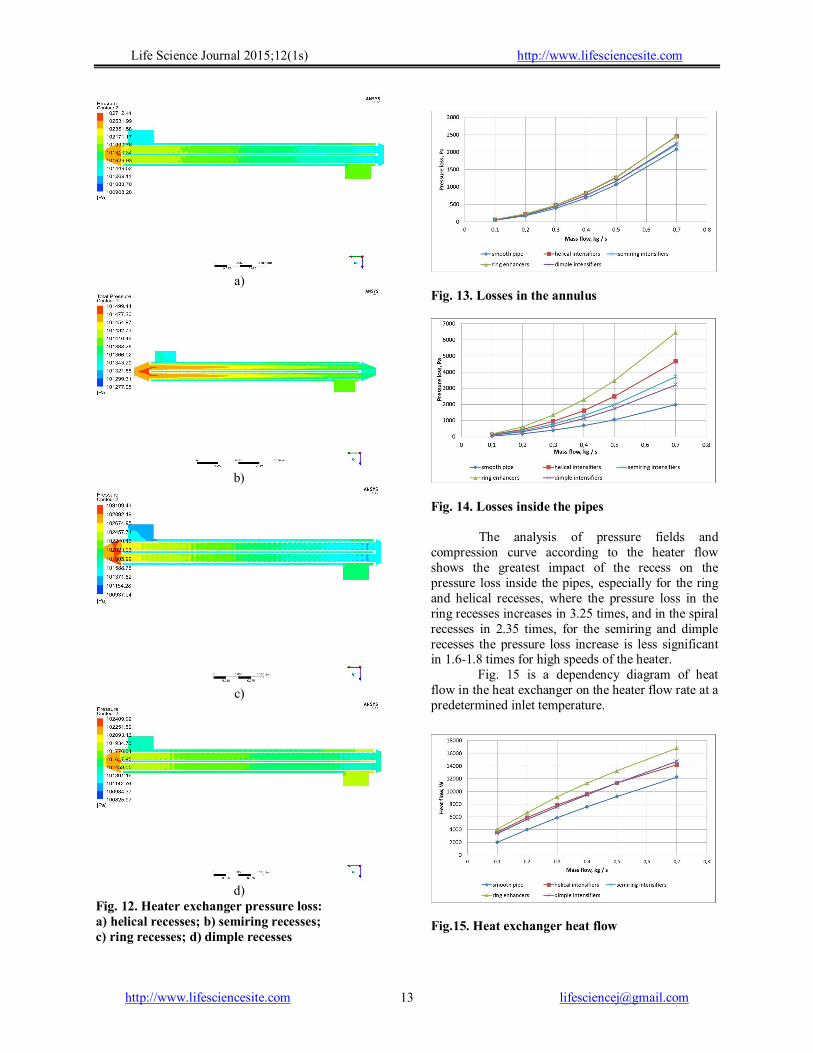
Fig. 12. Heater exchanger pressure loss: a) helical recesses; b) semiring recesses; c) ring recesses; d) dimple recesses
Fig. 13. Losses in the annulus
Fig. 14. Losses inside the pipes The analysis of pressure fields and compression curve according to the heater flow shows the greatest impact of the recess on the pressure loss inside the pipes, especially for the ring and helical recesses, where the pressure loss in the ring recesses increases in 3.25 times, and in the spiral recesses in 2.35 times, for the semiring and dimple recesses the pressure loss increase is less significant in 1.6-1.8 times for high speeds of the heater.
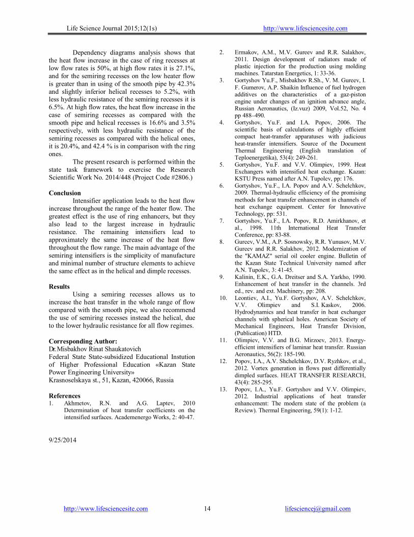
Fig. 15 is a dependency diagram of heat flow in the heat exchanger on the heater flow rate at a predetermined inlet temperature.
Fig.15. Heat exchanger heat flow
Life Science Journal 2015;12(1s) http://www.lifesciencesite.com
http://www.lifesciencesite.com [email protected] 14
Dependency diagrams analysis shows that the heat flow increase in the case of ring recesses at low flow rates is 50%, at high flow rates it is 27.1%, and for the semiring recesses on the low heater flow is greater than in using of the smooth pipe by 42.3% and slightly inferior helical recesses to 5.2%, with less hydraulic resistance of the semiring recesses it is 6.5%. At high flow rates, the heat flow increase in the case of semiring recesses as compared with the smooth pipe and helical recesses is 16.6% and 3.5% respectively, with less hydraulic resistance of the semiring recesses as compared with the helical ones, it is 20.4%, and 42.4 % is in comparison with the ring ones.
The present research is performed within the state task framework to exercise the Research Scientific Work No. 2014/448 (Project Code #2806.)
Conclusion
Intensifier application leads to the heat flow increase throughout the range of the heater flow. The greatest effect is the use of ring enhancers, but they also lead to the largest increase in hydraulic resistance. The remaining intensifiers lead to approximately the same increase of the heat flow throughout the flow range. The main advantage of the semiring intensifiers is the simplicity of manufacture and minimal number of structure elements to achieve the same effect as in the helical and dimple recesses.
Results
Using a semiring recesses allows us to increase the heat transfer in the whole range of flow compared with the smooth pipe, we also recommend the use of semiring recesses instead the helical, due to the lower hydraulic resistance for all flow regimes.
Corresponding Author: Dr. Misbakhov Rinat Shaukatovich Federal State State-subsidized Educational Instution of Higher Professional Education «Kazan State Power Engineering University» Krasnoselskaya st., 51, Kazan, 420066, Russia References 1. Akhmetov, R.N. and A.G. Laptev, 2010
Determination of heat transfer coefficients on the intensified surfaces. Academenergo Works, 2: 40-47.
2. Ermakov, A.M., M.V. Gureev and R.R. Salakhov, 2011. Design development of radiators made of plastic injection for the production using molding machines. Tatarstan Energetics, 1: 33-36.
3. Gortyshov Yu.F., Misbakhov R.Sh., V. M. Gureev, I. F. Gumerov, A.P. Shaikin Influence of fuel hydrogen additives on the characteristics of a gaz-piston engine under changes of an ignition advance angle, Russian Aeronautics, (Iz.vuz) 2009, Vol.52, No. 4 pp 488–490.
4. Gortyshov, Yu.F. and I.A. Popov, 2006. The scientific basis of calculations of highly efficient compact heat-transfer apparatuses with judicious heat-transfer intensifiers. Source of the Document Thermal Engineering (English translation of Teploenergetika), 53(4): 249-261.
5. Gortyshov, Yu.F. and V.V. Olimpiev, 1999. Heat Exchangers with intensified heat exchange. Kazan: KSTU Press named after A.N. Tupolev, pp: 176.
6. Gortyshov, Yu.F., I.A. Popov and A.V. Schelchkov, 2009. Thermal-hydraulic efficiency of the promising methods for heat transfer enhancement in channels of heat exchange equipment. Center for Innovative Technology, pp: 531.
7. Gortyshov, Yu.F., I.A. Popov, R.D. Amirkhanov, et al., 1998. 11th International Heat Transfer Conference, pp: 83-88.
8. Gureev, V.M., A.P. Sosnowsky, R.R. Yunusov, M.V. Gureev and R.R. Salakhov, 2012. Modernization of the "KAMAZ" serial oil cooler engine. Bulletin of the Kazan State Technical University named after A.N. Tupolev, 3: 41-45.
9. Kalinin, E.K., G.A. Dreitser and S.A. Yarkho, 1990. Enhancement of heat transfer in the channels. 3rd ed., rev. and ext. Machinery, pp: 208.
10. Leontiev, A.I., Yu.F. Gortyshov, A.V. Schelchkov, V.V. Olimpiev and S.I. Kaskov, 2006. Hydrodynamics and heat transfer in heat exchanger channels with spherical holes. American Society of Mechanical Engineers, Heat Transfer Division, (Publication) HTD.
11. Olimpiev, V.V. and B.G. Mirzoev, 2013. Energy-efficient intensifiers of laminar heat transfer. Russian Aeronautics, 56(2): 185-190.
12. Popov, I.A., A.V. Shchelchkov, D.V. Ryzhkov, et al., 2012. Vortex generation in flows past differentially dimpled surfaces. HEAT TRANSFER RESEARCH, 43(4): 285-295.
13. Popov, I.A., Yu.F. Gortyshov and V.V. Olimpiev, 2012. Industrial applications of heat transfer enhancement: The modern state of the problem (a Review). Thermal Engineering, 59(1): 1-12.
9/25/2014