Embed Size (px)
Citation preview

Liebert® Foundation™ Integrated Cabinet SolutionsUser Manual—Enclosure, Mini Computer Room and EX Expansion System
Liebert® Foundation™ User Manual i
Table of Content
Important Safety Instructions. . . . . . . . . . . . . . . . . . . . . . . . . . . . . . . . . . . . . . 1
1.0 Introduction . . . . . . . . . . . . . . . . . . . . . . . . . . . . . . . . . . . . . . . . . . . . . . . . . 4
1.1 About this Manual . . . . . . . . . . . . . . . . . . . . . . . . . . . . . . . . . . . . . . . . . . . . . . . . . . . . . . . . 4
2.0 Major Components . . . . . . . . . . . . . . . . . . . . . . . . . . . . . . . . . . . . . . . . . . . 5
2.1 Frame . . . . . . . . . . . . . . . . . . . . . . . . . . . . . . . . . . . . . . . . . . . . . . . . . . . . . . . . . . . . . . . . . 5
2.2 Enclosure . . . . . . . . . . . . . . . . . . . . . . . . . . . . . . . . . . . . . . . . . . . . . . . . . . . . . . . . . . . . . . 5
2.3 Doors. . . . . . . . . . . . . . . . . . . . . . . . . . . . . . . . . . . . . . . . . . . . . . . . . . . . . . . . . . . . . . . . . . 5
2.4 Side Panels . . . . . . . . . . . . . . . . . . . . . . . . . . . . . . . . . . . . . . . . . . . . . . . . . . . . . . . . . . . . . 6
2.5 Foundation EX Expansion System . . . . . . . . . . . . . . . . . . . . . . . . . . . . . . . . . . . . . . . . . . . 6
2.6 Power . . . . . . . . . . . . . . . . . . . . . . . . . . . . . . . . . . . . . . . . . . . . . . . . . . . . . . . . . . . . . . . . . 6
2.6.1 Uninterruptible Power Supply . . . . . . . . . . . . . . . . . . . . . . . . . . . . . . . . . . . . . . . . . . . . . . . 6
2.6.2 MP Advanced Power Strips . . . . . . . . . . . . . . . . . . . . . . . . . . . . . . . . . . . . . . . . . . . . . . . . 6
2.7 Environmental . . . . . . . . . . . . . . . . . . . . . . . . . . . . . . . . . . . . . . . . . . . . . . . . . . . . . . . . . . . 7
2.7.1 Fan Cooling System and Options . . . . . . . . . . . . . . . . . . . . . . . . . . . . . . . . . . . . . . . . . . . . 7
2.7.2 Environmental Control Module . . . . . . . . . . . . . . . . . . . . . . . . . . . . . . . . . . . . . . . . . . . . . . 7
2.7.3 ECM Heat Rejection . . . . . . . . . . . . . . . . . . . . . . . . . . . . . . . . . . . . . . . . . . . . . . . . . . . . . . 7
2.7.4 Back-Up Cooling Module (BCM). . . . . . . . . . . . . . . . . . . . . . . . . . . . . . . . . . . . . . . . . . . . . 7
2.8 Monitoring . . . . . . . . . . . . . . . . . . . . . . . . . . . . . . . . . . . . . . . . . . . . . . . . . . . . . . . . . . . . . . 8
3.0 Installation . . . . . . . . . . . . . . . . . . . . . . . . . . . . . . . . . . . . . . . . . . . . . . . . . . 9
3.1 Inspection . . . . . . . . . . . . . . . . . . . . . . . . . . . . . . . . . . . . . . . . . . . . . . . . . . . . . . . . . . . . . . 9
3.2 Required Setup Equipment . . . . . . . . . . . . . . . . . . . . . . . . . . . . . . . . . . . . . . . . . . . . . . . . . 9
3.3 Electrical Requirements . . . . . . . . . . . . . . . . . . . . . . . . . . . . . . . . . . . . . . . . . . . . . . . . . . . 9
3.3.1 Environmental Control Module (ECM) . . . . . . . . . . . . . . . . . . . . . . . . . . . . . . . . . . . . . . . . 9
3.3.2 Backup Cooling Module (BCM). . . . . . . . . . . . . . . . . . . . . . . . . . . . . . . . . . . . . . . . . . . . . . 9
3.3.3 FAN Cooling . . . . . . . . . . . . . . . . . . . . . . . . . . . . . . . . . . . . . . . . . . . . . . . . . . . . . . . . . . . . 9
3.3.4 Uninterruptible Power Supply (UPS). . . . . . . . . . . . . . . . . . . . . . . . . . . . . . . . . . . . . . . . . . 9
3.3.5 MP Advanced Power Strips . . . . . . . . . . . . . . . . . . . . . . . . . . . . . . . . . . . . . . . . . . . . . . . 10
3.4 Unloading the Foundation . . . . . . . . . . . . . . . . . . . . . . . . . . . . . . . . . . . . . . . . . . . . . . . . . 10
3.4.1 Unloading a Foundation Enclosure (HK/RK) . . . . . . . . . . . . . . . . . . . . . . . . . . . . . . . . . . 10
3.4.2 Unloading a Foundation MCR (HD/RD) . . . . . . . . . . . . . . . . . . . . . . . . . . . . . . . . . . . . . . 10
3.5 Mini Computer Room Site Preparation . . . . . . . . . . . . . . . . . . . . . . . . . . . . . . . . . . . . . . . 11
3.5.1 Equipment Layout . . . . . . . . . . . . . . . . . . . . . . . . . . . . . . . . . . . . . . . . . . . . . . . . . . . . . . . 12
3.5.2 Wall-Mount Enclosures . . . . . . . . . . . . . . . . . . . . . . . . . . . . . . . . . . . . . . . . . . . . . . . . . . . 13
ii Liebert® Foundation™ User Manual
3.6 Frame and Enclosure Configurations . . . . . . . . . . . . . . . . . . . . . . . . . . . . . . . . . . . . . . . . 13
3.6.1 Internal Mounting Rails . . . . . . . . . . . . . . . . . . . . . . . . . . . . . . . . . . . . . . . . . . . . . . . . . . . 13
3.6.2 Front- and Rear-Mount Rails—Position . . . . . . . . . . . . . . . . . . . . . . . . . . . . . . . . . . . . . . 14
3.6.3 Center-Mount Rails—Position. . . . . . . . . . . . . . . . . . . . . . . . . . . . . . . . . . . . . . . . . . . . . . 14
3.7 Mounting Hardware . . . . . . . . . . . . . . . . . . . . . . . . . . . . . . . . . . . . . . . . . . . . . . . . . . . . . . 14
3.8 Door—Remove and Reverse . . . . . . . . . . . . . . . . . . . . . . . . . . . . . . . . . . . . . . . . . . . . . . 15
3.8.1 Remove the Door . . . . . . . . . . . . . . . . . . . . . . . . . . . . . . . . . . . . . . . . . . . . . . . . . . . . . . . 15
3.8.2 Quick Door Removal. . . . . . . . . . . . . . . . . . . . . . . . . . . . . . . . . . . . . . . . . . . . . . . . . . . . . 15
3.8.3 Reverse the Door . . . . . . . . . . . . . . . . . . . . . . . . . . . . . . . . . . . . . . . . . . . . . . . . . . . . . . . 15
3.8.4 Reverse the Door Handle . . . . . . . . . . . . . . . . . . . . . . . . . . . . . . . . . . . . . . . . . . . . . . . . . 15
3.9 Side Panels—Remove and Replace. . . . . . . . . . . . . . . . . . . . . . . . . . . . . . . . . . . . . . . . . 16
3.9.1 Remove a Panel . . . . . . . . . . . . . . . . . . . . . . . . . . . . . . . . . . . . . . . . . . . . . . . . . . . . . . . . 16
3.9.2 Replace a Panel . . . . . . . . . . . . . . . . . . . . . . . . . . . . . . . . . . . . . . . . . . . . . . . . . . . . . . . . 16
3.10 Cluster Configuration. . . . . . . . . . . . . . . . . . . . . . . . . . . . . . . . . . . . . . . . . . . . . . . . . . . . 16
4.0 Foundation EX—Expansion System . . . . . . . . . . . . . . . . . . . . . . . . . . . . 17
4.1 Installation . . . . . . . . . . . . . . . . . . . . . . . . . . . . . . . . . . . . . . . . . . . . . . . . . . . . . . . . . . . . . 17
4.1.1 Installing EX Components on a Single Foundation. . . . . . . . . . . . . . . . . . . . . . . . . . . . . . 17
4.1.1.1 Attach the EX Tie Bars. . . . . . . . . . . . . . . . . . . . . . . . . . . . . . . . . . . . . . . . . . . . 19
4.1.1.2 Final Assembly for Single Foundation . . . . . . . . . . . . . . . . . . . . . . . . . . . . . . . . 19
4.1.2 Stacking EX Expansion Channels . . . . . . . . . . . . . . . . . . . . . . . . . . . . . . . . . . . . . . . . . . 20
4.2 EX Expansion Channel Installation for Clustered Foundation Units . . . . . . . . . . . . . . . . . 21
4.3 Equipment Mounting in/with the EX Expansion Channels . . . . . . . . . . . . . . . . . . . . . . . . 22
4.3.1 Installing EX Rack-mount Adapters . . . . . . . . . . . . . . . . . . . . . . . . . . . . . . . . . . . . . . . . . 23
4.3.2 Install Liebert MP Advanced Power Strips in the Liebert EX Expansion Channel . . . . . . 24
4.3.3 Install Internal Mounting Rails in the EX Expansion Channel . . . . . . . . . . . . . . . . . . . . . . 26
5.0 General Cable Management Options. . . . . . . . . . . . . . . . . . . . . . . . . . . . 27
5.1 Cable Management . . . . . . . . . . . . . . . . . . . . . . . . . . . . . . . . . . . . . . . . . . . . . . . . . . . . . . 27
5.2 Cable Management Considerations . . . . . . . . . . . . . . . . . . . . . . . . . . . . . . . . . . . . . . . . . 27
5.3 Cable Access—Sealed Units . . . . . . . . . . . . . . . . . . . . . . . . . . . . . . . . . . . . . . . . . . . . . . 28
5.3.1 Top Cover and Back of Sealed Units . . . . . . . . . . . . . . . . . . . . . . . . . . . . . . . . . . . . . . . . 28
5.3.2 Base of Sealed Units . . . . . . . . . . . . . . . . . . . . . . . . . . . . . . . . . . . . . . . . . . . . . . . . . . . . 28

Liebert® Foundation™ User Manual iii
5.4 Cable Access—Non-Sealed Units. . . . . . . . . . . . . . . . . . . . . . . . . . . . . . . . . . . . . . . . . . . 29
5.4.1 Top Cover and Back of Non-Sealed Units . . . . . . . . . . . . . . . . . . . . . . . . . . . . . . . . . . . . 29
5.4.2 Base of Non-Sealed Units. . . . . . . . . . . . . . . . . . . . . . . . . . . . . . . . . . . . . . . . . . . . . . . . . 29
5.5 EX Cable Management Channels—Optional . . . . . . . . . . . . . . . . . . . . . . . . . . . . . . . . . . 29
5.5.1 Field-Mounting Options for EX Cable Management Channels . . . . . . . . . . . . . . . . . . . . . 29
5.5.2 Supporting and Arranging Cables. . . . . . . . . . . . . . . . . . . . . . . . . . . . . . . . . . . . . . . . . . . 31
6.0 Startup . . . . . . . . . . . . . . . . . . . . . . . . . . . . . . . . . . . . . . . . . . . . . . . . . . . . 34
7.0 Operation . . . . . . . . . . . . . . . . . . . . . . . . . . . . . . . . . . . . . . . . . . . . . . . . . . 35
7.1 Environmental . . . . . . . . . . . . . . . . . . . . . . . . . . . . . . . . . . . . . . . . . . . . . . . . . . . . . . . . . . 35
7.1.1 ECM (Environmental Control Module) . . . . . . . . . . . . . . . . . . . . . . . . . . . . . . . . . . . . . . . 35
7.1.2 Backup Cooling Module (BCM). . . . . . . . . . . . . . . . . . . . . . . . . . . . . . . . . . . . . . . . . . . . . 35
7.1.3 BCM Energy Saver . . . . . . . . . . . . . . . . . . . . . . . . . . . . . . . . . . . . . . . . . . . . . . . . . . . . . . 36
7.1.4 Active Heat Rejection Options . . . . . . . . . . . . . . . . . . . . . . . . . . . . . . . . . . . . . . . . . . . . . 36
7.1.5 FAN Cooling . . . . . . . . . . . . . . . . . . . . . . . . . . . . . . . . . . . . . . . . . . . . . . . . . . . . . . . . . . . 36
7.2 Uninterruptible Power Supply . . . . . . . . . . . . . . . . . . . . . . . . . . . . . . . . . . . . . . . . . . . . . . 36
7.3 SiteNet Integrator . . . . . . . . . . . . . . . . . . . . . . . . . . . . . . . . . . . . . . . . . . . . . . . . . . . . . . . 37
7.3.1 SNI Sensor Options . . . . . . . . . . . . . . . . . . . . . . . . . . . . . . . . . . . . . . . . . . . . . . . . . . . . . 37
8.0 Optional Equipment . . . . . . . . . . . . . . . . . . . . . . . . . . . . . . . . . . . . . . . . . 39
8.1 Enclosure Systems . . . . . . . . . . . . . . . . . . . . . . . . . . . . . . . . . . . . . . . . . . . . . . . . . . . . . . 39
8.1.1 Internal Mounting Rails . . . . . . . . . . . . . . . . . . . . . . . . . . . . . . . . . . . . . . . . . . . . . . . . . . . 39
8.1.2 Door/Panel Options. . . . . . . . . . . . . . . . . . . . . . . . . . . . . . . . . . . . . . . . . . . . . . . . . . . . . . 39
8.1.3 General Enclosure Options. . . . . . . . . . . . . . . . . . . . . . . . . . . . . . . . . . . . . . . . . . . . . . . . 39
8.1.4 Power . . . . . . . . . . . . . . . . . . . . . . . . . . . . . . . . . . . . . . . . . . . . . . . . . . . . . . . . . . . . . . . . 39
8.1.5 Power Strips . . . . . . . . . . . . . . . . . . . . . . . . . . . . . . . . . . . . . . . . . . . . . . . . . . . . . . . . . . . 40
8.2 Environmental . . . . . . . . . . . . . . . . . . . . . . . . . . . . . . . . . . . . . . . . . . . . . . . . . . . . . . . . . . 40
8.2.1 ECM Cooling Systems and Options . . . . . . . . . . . . . . . . . . . . . . . . . . . . . . . . . . . . . . . . . 40
8.2.2 BCM Cooling Systems and Options . . . . . . . . . . . . . . . . . . . . . . . . . . . . . . . . . . . . . . . . . 40
8.2.3 FAN Cooling Systems & Options . . . . . . . . . . . . . . . . . . . . . . . . . . . . . . . . . . . . . . . . . . . 40
8.3 Monitoring Options . . . . . . . . . . . . . . . . . . . . . . . . . . . . . . . . . . . . . . . . . . . . . . . . . . . . . . 41
8.4 Mounting Options . . . . . . . . . . . . . . . . . . . . . . . . . . . . . . . . . . . . . . . . . . . . . . . . . . . . . . . 41
iv Liebert® Foundation™ User Manual
9.0 MP Advanced Power Strips—Installation . . . . . . . . . . . . . . . . . . . . . . . . 42
9.1 Save These Instructions—MP Advanced Power Strips . . . . . . . . . . . . . . . . . . . . . . . . . . 42
9.2 General Considerations. . . . . . . . . . . . . . . . . . . . . . . . . . . . . . . . . . . . . . . . . . . . . . . . . . . 43
9.3 Vertical or Horizontal-Mounting . . . . . . . . . . . . . . . . . . . . . . . . . . . . . . . . . . . . . . . . . . . . . 43
9.4 Mounting MP Advanced Power Strips Vertically . . . . . . . . . . . . . . . . . . . . . . . . . . . . . . . . 44
9.4.1 Attach Brackets to the Power Strip—Vertical-Mount Inside the Rail. . . . . . . . . . . . . . . . . 44
9.4.2 Attach the Power Strip to Corner Post—Vertical-Mount Inside Corner Post . . . . . . . . . . 45
9.4.3 Attach Power Strip to the Rail—Vertical-Mount Outside the Rail . . . . . . . . . . . . . . . . . . . 46
9.5 Mounting the MP Advanced Power Strip or Access Server Horizontally . . . . . . . . . . . . . 47
9.5.1 Attach Mounting Brackets to the Power Strip or Access Server—Horizontal-Mount . . . . 47
9.5.2 Attach the Access Server or Power Strip to Rack Rails—Horizontal-Mount. . . . . . . . . . . 48
10.0 Using the Liebert MP Advanced Power Strips . . . . . . . . . . . . . . . . . . . 49
10.1 Monitoring and Controlling Methods . . . . . . . . . . . . . . . . . . . . . . . . . . . . . . . . . . . . . . . . 49
10.2 Monitoring Connections—Low Voltage Wiring . . . . . . . . . . . . . . . . . . . . . . . . . . . . . . . . 49
10.2.1 What’s Included . . . . . . . . . . . . . . . . . . . . . . . . . . . . . . . . . . . . . . . . . . . . . . . . . . . . . . . 49
10.2.2 Configuration with OpenComms EM. . . . . . . . . . . . . . . . . . . . . . . . . . . . . . . . . . . . . . . . 50
10.2.3 Assign an IP Address . . . . . . . . . . . . . . . . . . . . . . . . . . . . . . . . . . . . . . . . . . . . . . . . . . . 50
10.2.4 Open the Web Interface and Log In . . . . . . . . . . . . . . . . . . . . . . . . . . . . . . . . . . . . . . . . 51
10.2.5 Configuration with Liebert MP-S Access Server . . . . . . . . . . . . . . . . . . . . . . . . . . . . . . . 51
10.2.6 Make Connections . . . . . . . . . . . . . . . . . . . . . . . . . . . . . . . . . . . . . . . . . . . . . . . . . . . . . 52
10.2.7 Establish Communication With Card . . . . . . . . . . . . . . . . . . . . . . . . . . . . . . . . . . . . . . . 52
10.2.7.1 Set the Access Server’s IP Address . . . . . . . . . . . . . . . . . . . . . . . . . . . . . . . . 52
11.0 Monitoring and Controlling MP Advanced Power Strips with OpenComms EM PDU . . . . . . . . . . . . . . . . . . . . . . . . . . . . . . . . . . 54
11.1 Open the Web Interface and Log In . . . . . . . . . . . . . . . . . . . . . . . . . . . . . . . . . . . . . . . . 54
11.2 Main Parts of the OpenComms EM PDU Web Interface. . . . . . . . . . . . . . . . . . . . . . . . . 55
11.3 Web Interface Tabs. . . . . . . . . . . . . . . . . . . . . . . . . . . . . . . . . . . . . . . . . . . . . . . . . . . . . 56
11.4 Color-Coded Status Indicators . . . . . . . . . . . . . . . . . . . . . . . . . . . . . . . . . . . . . . . . . . . . 57
11.5 View Summary Data Tab . . . . . . . . . . . . . . . . . . . . . . . . . . . . . . . . . . . . . . . . . . . . . . . . 57
11.5.1 Types of Information . . . . . . . . . . . . . . . . . . . . . . . . . . . . . . . . . . . . . . . . . . . . . . . . . . . . 58
11.5.2 Update the Information . . . . . . . . . . . . . . . . . . . . . . . . . . . . . . . . . . . . . . . . . . . . . . . . . . 58
Liebert® Foundation™ User Manual v
11.6 View the Power Data Tab . . . . . . . . . . . . . . . . . . . . . . . . . . . . . . . . . . . . . . . . . . . . . . . . 58
11.7 Change Threshold Settings for Alarm Signals and Alerts . . . . . . . . . . . . . . . . . . . . . . . . 59
11.8 View the Alerts Tab . . . . . . . . . . . . . . . . . . . . . . . . . . . . . . . . . . . . . . . . . . . . . . . . . . . . . 60
11.8.1 Enable E-mail Alerts . . . . . . . . . . . . . . . . . . . . . . . . . . . . . . . . . . . . . . . . . . . . . . . . . . . . 61
11.8.2 Set Up Modem . . . . . . . . . . . . . . . . . . . . . . . . . . . . . . . . . . . . . . . . . . . . . . . . . . . . . . . . 62
11.8.3 Set Up SNMP Traps . . . . . . . . . . . . . . . . . . . . . . . . . . . . . . . . . . . . . . . . . . . . . . . . . . . . 63
11.9 View the Security Tab . . . . . . . . . . . . . . . . . . . . . . . . . . . . . . . . . . . . . . . . . . . . . . . . . . . 64
11.9.1 Create a Password for the Default Liebert Account—Administrators Only. . . . . . . . . . . 64
11.10 Exit the Web Interface. . . . . . . . . . . . . . . . . . . . . . . . . . . . . . . . . . . . . . . . . . . . . . . . . . 64
12.0 Monitoring and Controlling the Liebert MP Advanced Power Strips with the MP Advanced Access Server . . . . . . . . . . . . . . . . . . . . . . . . . 65
12.1 Monitoring and Controlling the MP Advanced Power Strip . . . . . . . . . . . . . . . . . . . . . . . 66
12.1.1 Open the Web Interface . . . . . . . . . . . . . . . . . . . . . . . . . . . . . . . . . . . . . . . . . . . . . . . . . 66
12.2 Accessing Receptacle Controls and Status . . . . . . . . . . . . . . . . . . . . . . . . . . . . . . . . . . 67
12.3 Changing MP Advanced Power Strip Parameters . . . . . . . . . . . . . . . . . . . . . . . . . . . . . 68
12.3.1 Opening HyperTerminal . . . . . . . . . . . . . . . . . . . . . . . . . . . . . . . . . . . . . . . . . . . . . . . . . 68
12.3.2 Customizing MP Advanced Power Strip Alarm Thresholds . . . . . . . . . . . . . . . . . . . . . . 69
12.3.2.1 Accessing RPC Management . . . . . . . . . . . . . . . . . . . . . . . . . . . . . . . . . . . . . 70
12.3.2.2 Changing Alarm Thresholds. . . . . . . . . . . . . . . . . . . . . . . . . . . . . . . . . . . . . . . 70
12.3.3 Recommended Alarm Thresholds for Under Voltage, Over Voltage and Low Current. . 71
12.3.4 Receiving Alarms . . . . . . . . . . . . . . . . . . . . . . . . . . . . . . . . . . . . . . . . . . . . . . . . . . . . . . 71
12.3.5 Customizing MP Advanced Power Strip Settings—Outlet Groups . . . . . . . . . . . . . . . . . 71
12.3.6 Accessing Outlet Controls. . . . . . . . . . . . . . . . . . . . . . . . . . . . . . . . . . . . . . . . . . . . . . . . 74
13.0 Maintenance. . . . . . . . . . . . . . . . . . . . . . . . . . . . . . . . . . . . . . . . . . . . . . . 76
13.1 Periodic Maintenance . . . . . . . . . . . . . . . . . . . . . . . . . . . . . . . . . . . . . . . . . . . . . . . . . . . 77
13.1.1 Mini Computer Room . . . . . . . . . . . . . . . . . . . . . . . . . . . . . . . . . . . . . . . . . . . . . . . . . . . 77
13.1.2 Rack-Mount ECM . . . . . . . . . . . . . . . . . . . . . . . . . . . . . . . . . . . . . . . . . . . . . . . . . . . . . . 77
13.1.3 Top-Mount ECM . . . . . . . . . . . . . . . . . . . . . . . . . . . . . . . . . . . . . . . . . . . . . . . . . . . . . . . 77
13.1.4 Cleaning the Optional FAN Air Filter . . . . . . . . . . . . . . . . . . . . . . . . . . . . . . . . . . . . . . . . 77
13.2 MCR Start-Up Inspection Checklist. . . . . . . . . . . . . . . . . . . . . . . . . . . . . . . . . . . . . . . . . 78
13.2.1 Site Conditions . . . . . . . . . . . . . . . . . . . . . . . . . . . . . . . . . . . . . . . . . . . . . . . . . . . . . . . . 78
13.2.2 Unit Start-Up and Operation . . . . . . . . . . . . . . . . . . . . . . . . . . . . . . . . . . . . . . . . . . . . . . 78
vi Liebert® Foundation™ User Manual
14.0 Installation Drawings . . . . . . . . . . . . . . . . . . . . . . . . . . . . . . . . . . . . . . . 79
15.0 Specifications . . . . . . . . . . . . . . . . . . . . . . . . . . . . . . . . . . . . . . . . . . . . . 89
15.1 Cooling Systems . . . . . . . . . . . . . . . . . . . . . . . . . . . . . . . . . . . . . . . . . . . . . . . . . . . . . . . 89
15.2 Power Systems . . . . . . . . . . . . . . . . . . . . . . . . . . . . . . . . . . . . . . . . . . . . . . . . . . . . . . . . 91
15.3 Optional Managed Power - Advanced Power Strips, Vertical- or Horizontal-Mount . . . . 92
vii Liebert® Foundation™
List of FiguresFigure 3-1: Recommended equipment stacking arrangement . . . . . . . . . . . . . . . . . . . . . . . . . . . . . . . . . . . . . . . . 12
Figure 4-1: Align EX Expansion Channel for attachment . . . . . . . . . . . . . . . . . . . . . . . . . . . . . . . . . . . . . . . . . . . . 17
Figure 4-2: EX Expansion Channel attachment . . . . . . . . . . . . . . . . . . . . . . . . . . . . . . . . . . . . . . . . . . . . . . . . . . . 18
Figure 4-3: Attaching EX Tie Bars . . . . . . . . . . . . . . . . . . . . . . . . . . . . . . . . . . . . . . . . . . . . . . . . . . . . . . . . . . . . . 19
Figure 4-4: Inserting spacers for cluster arrangement . . . . . . . . . . . . . . . . . . . . . . . . . . . . . . . . . . . . . . . . . . . . . . 21
Figure 4-5: Clustered Foundation units with EX assembly attached . . . . . . . . . . . . . . . . . . . . . . . . . . . . . . . . . . . 22
Figure 4-6: Key slots and T-slots in EX Expansion Channel . . . . . . . . . . . . . . . . . . . . . . . . . . . . . . . . . . . . . . . . . 22
Figure 4-7: EX Rack-mount Adapter- 2U . . . . . . . . . . . . . . . . . . . . . . . . . . . . . . . . . . . . . . . . . . . . . . . . . . . . . . . . 23
Figure 5: Zero-U mounting of Liebert Rack-mount Adapter in Liebert EX Expansion Channel . . . . . . . . . . . . . . . 23
Figure 4-1: Mounting brackets for longer Liebert MP Advanced Power Strip . . . . . . . . . . . . . . . . . . . . . . . . . . . . 24
Figure 4-2: Longer Liebert MP Advanced Power Strips attached to Liebert EX Expansion Channel . . . . . . . . . . 25
Figure 5-1: Cable rings, Velcro straps on Foundation rails . . . . . . . . . . . . . . . . . . . . . . . . . . . . . . . . . . . . . . . . . . 27
Figure 5-2: EX Cable Management Channel mounting locations and lengths. . . . . . . . . . . . . . . . . . . . . . . . . . . . 30
Figure 5-3: EX Cable Management Channels as trough . . . . . . . . . . . . . . . . . . . . . . . . . . . . . . . . . . . . . . . . . . . . 31
Figure 5-4: EX cable management accessories: Velcro Cable Straps, EX Cable Spools, EX Cable Rings . . . . . 32
Figure 5-5: EX cable management accessories: EX Cable Tray . . . . . . . . . . . . . . . . . . . . . . . . . . . . . . . . . . . . . . 33
Figure 9-1: Hardware components for vertical-mount . . . . . . . . . . . . . . . . . . . . . . . . . . . . . . . . . . . . . . . . . . . . . . 44
Figure 9-2: Liebert MP Advanced Power Strip mounted vertically inside the rail. . . . . . . . . . . . . . . . . . . . . . . . . . 45
Figure 9-3: Marking mounting position. . . . . . . . . . . . . . . . . . . . . . . . . . . . . . . . . . . . . . . . . . . . . . . . . . . . . . . . . . 45
Figure 9-4: Liebert MP Advanced Power Strip ready for vertical installation outside a rail . . . . . . . . . . . . . . . . . . 46
Figure 9-5: Hardware components for horizontal-mount . . . . . . . . . . . . . . . . . . . . . . . . . . . . . . . . . . . . . . . . . . . . 47
Figure 9-6: Liebert MP Advanced Power Strip ready for installation in a rack—horizontal-mount. . . . . . . . . . . . . 47
Figure 9-7: Rack-mounting the power strip or access server. . . . . . . . . . . . . . . . . . . . . . . . . . . . . . . . . . . . . . . . . 48
Figure 10-1: Communication ports on OpenComms EM PDU and MP Advanced Power Strip. . . . . . . . . . . . . . . 49
Figure 10-2: Use IPSet to set power strip’s IP address . . . . . . . . . . . . . . . . . . . . . . . . . . . . . . . . . . . . . . . . . . . . . 50
Figure 10-3: Communication ports on MP Advanced Power Strip and MP Advanced Access Server. . . . . . . . . . 51
Figure 10-4: Disabling DHCP and entering IP address . . . . . . . . . . . . . . . . . . . . . . . . . . . . . . . . . . . . . . . . . . . . . 53
Figure 11-1: OpenComms EM PDU ports and indicators . . . . . . . . . . . . . . . . . . . . . . . . . . . . . . . . . . . . . . . . . . . 54
Figure 11-2: MP Advanced Power Strip login window . . . . . . . . . . . . . . . . . . . . . . . . . . . . . . . . . . . . . . . . . . . . . . 55
Figure 11-3: Web interface components . . . . . . . . . . . . . . . . . . . . . . . . . . . . . . . . . . . . . . . . . . . . . . . . . . . . . . . . 55
Figure 11-4: Color coded display—example . . . . . . . . . . . . . . . . . . . . . . . . . . . . . . . . . . . . . . . . . . . . . . . . . . . . . 57
Figure 11-5: Summary window components . . . . . . . . . . . . . . . . . . . . . . . . . . . . . . . . . . . . . . . . . . . . . . . . . . . . . 57
Figure 11-6: Power data window components . . . . . . . . . . . . . . . . . . . . . . . . . . . . . . . . . . . . . . . . . . . . . . . . . . . . 58
Figure 11-7: Status heading links to threshold settings . . . . . . . . . . . . . . . . . . . . . . . . . . . . . . . . . . . . . . . . . . . . . 59
Figure 11-8: Alerts tab components . . . . . . . . . . . . . . . . . . . . . . . . . . . . . . . . . . . . . . . . . . . . . . . . . . . . . . . . . . . . 60
Figure 11-9: Alerts tab . . . . . . . . . . . . . . . . . . . . . . . . . . . . . . . . . . . . . . . . . . . . . . . . . . . . . . . . . . . . . . . . . . . . . . 61
Figure 11-10: Alerts tab—modem components . . . . . . . . . . . . . . . . . . . . . . . . . . . . . . . . . . . . . . . . . . . . . . . . . . . 62
Figure 11-11: Alerts tab—SNMP Traps components . . . . . . . . . . . . . . . . . . . . . . . . . . . . . . . . . . . . . . . . . . . . . . . 63
Figure 11-12: Security window components . . . . . . . . . . . . . . . . . . . . . . . . . . . . . . . . . . . . . . . . . . . . . . . . . . . . . 64
Figure 12-1: MP Access Server with MP-DS74 modules. . . . . . . . . . . . . . . . . . . . . . . . . . . . . . . . . . . . . . . . . . . . 65
Figure 12-2: Web interface components—MP Access Server . . . . . . . . . . . . . . . . . . . . . . . . . . . . . . . . . . . . . . . . 66
Liebert® Foundation™ viii
Figure 12-3: Access module status and control window . . . . . . . . . . . . . . . . . . . . . . . . . . . . . . . . . . . . . . . . . . . . 67
Figure 12-4: MP Advanced Power Strip control options. . . . . . . . . . . . . . . . . . . . . . . . . . . . . . . . . . . . . . . . . . . . . 69
Figure 12-5: Changing the Temperature Alarm Threshold . . . . . . . . . . . . . . . . . . . . . . . . . . . . . . . . . . . . . . . . . . . 70
Figure 12-6: Grouping outlets . . . . . . . . . . . . . . . . . . . . . . . . . . . . . . . . . . . . . . . . . . . . . . . . . . . . . . . . . . . . . . . . 72
Figure 12-7: Naming outlet groups . . . . . . . . . . . . . . . . . . . . . . . . . . . . . . . . . . . . . . . . . . . . . . . . . . . . . . . . . . . . 73
Figure 12-8: Outlet controls on MP Advanced Access Server . . . . . . . . . . . . . . . . . . . . . . . . . . . . . . . . . . . . . . . . 74
Figure 12-9: Outlet group details . . . . . . . . . . . . . . . . . . . . . . . . . . . . . . . . . . . . . . . . . . . . . . . . . . . . . . . . . . . . . . 75
Figure 14-1: Foundation 12U low profile wall-mount dimensions and features . . . . . . . . . . . . . . . . . . . . . . . . . . . 79
Figure 14-2: Foundation 12U hinged body wall-mount dimensions and features . . . . . . . . . . . . . . . . . . . . . . . . . 80
Figure 14-3: Foundation 22U frame dimensions and features. . . . . . . . . . . . . . . . . . . . . . . . . . . . . . . . . . . . . . . . 81
Figure 14-4: Foundation 42U frame dimensions and features. . . . . . . . . . . . . . . . . . . . . . . . . . . . . . . . . . . . . . . . 82
Figure 14-5: Foundation 46U frame dimensions and features. . . . . . . . . . . . . . . . . . . . . . . . . . . . . . . . . . . . . . . . 83
Figure 14-6: Foundation 22U Mini Computer Room with top-mount ECM dimensions and features . . . . . . . . . . 84
Figure 14-7: Foundation 42U Mini Computer Room with rack-mount ECM dimensions and features. . . . . . . . . . 85
Figure 14-8: Foundation 42U Mini Computer Room with top-mount ECM dimensions and features . . . . . . . . . . 86
Figure 14-9: Foundation 46U Mini Computer Room with rack-mount ECM dimensions and features. . . . . . . . . . 87
Figure 14-10: Foundation 46U Mini Computer Room with top-mount ECM dimensions and features . . . . . . . . . 88
Figure 15-1: Foundation model numbers . . . . . . . . . . . . . . . . . . . . . . . . . . . . . . . . . . . . . . . . . . . . . . . . . . . . . . . . 89
Figure 15-2: ECM recommended operating conditions to prevent excess cabinet condensation . . . . . . . . . . . . . 90
ix Liebert® Foundation™ User Manual
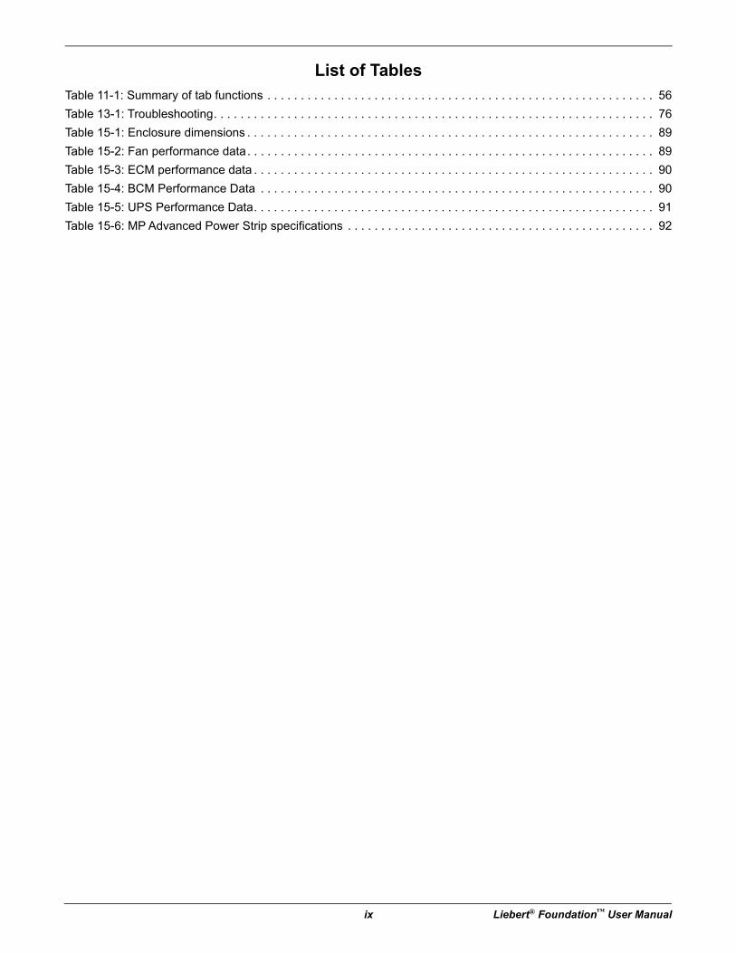
List of TablesTable 11-1: Summary of tab functions . . . . . . . . . . . . . . . . . . . . . . . . . . . . . . . . . . . . . . . . . . . . . . . . . . . . . . . . . . 56
Table 13-1: Troubleshooting. . . . . . . . . . . . . . . . . . . . . . . . . . . . . . . . . . . . . . . . . . . . . . . . . . . . . . . . . . . . . . . . . . 76
Table 15-1: Enclosure dimensions . . . . . . . . . . . . . . . . . . . . . . . . . . . . . . . . . . . . . . . . . . . . . . . . . . . . . . . . . . . . . 89
Table 15-2: Fan performance data. . . . . . . . . . . . . . . . . . . . . . . . . . . . . . . . . . . . . . . . . . . . . . . . . . . . . . . . . . . . . 89
Table 15-3: ECM performance data . . . . . . . . . . . . . . . . . . . . . . . . . . . . . . . . . . . . . . . . . . . . . . . . . . . . . . . . . . . . 90
Table 15-4: BCM Performance Data . . . . . . . . . . . . . . . . . . . . . . . . . . . . . . . . . . . . . . . . . . . . . . . . . . . . . . . . . . . 90
Table 15-5: UPS Performance Data. . . . . . . . . . . . . . . . . . . . . . . . . . . . . . . . . . . . . . . . . . . . . . . . . . . . . . . . . . . . 91
Table 15-6: MP Advanced Power Strip specifications . . . . . . . . . . . . . . . . . . . . . . . . . . . . . . . . . . . . . . . . . . . . . . 92

Important Safety Instructions
Liebert® Foundation™ User Manual 1
Important Safety Instructions
SAVE THESE INSTRUCTIONSThis manual contains important instructions that should be closely followed during installation and maintenance of this unit. Read all safety and operating instructions before attempting to operate the Foundation. Adhere to all warnings on the unit and in this manual. Follow all operating and user instructions.
This product is designed for commercial / industrial use only. This product is not intended for use with life support or other U.S. FDA designated “critical” devices. Maximum load must not exceed that shown on the Foundation rating label.
Operate this product in an indoor environment at an ambient temperature of 65°F to 105°F (23°C to 40°C). Install in a clean environment, free from moisture, flammable liquids, gases, and corrosive substances.
See Figure 15-2, page 90, for recommended operating conditions to prevent excessive cabinet condensation. Keep cabinet doors closed and ensure that wiring entrances are sealed tightly to minimize non-conditioned room-air intrusion into the cabinet.
Where applicable, this product must be permanently connected and powered from a suitable single-phase AC supply rated in accordance with the equipment data plate. It must be suitably grounded and protected by a circuit breaker or fuse.
This equipment complies with the requirements of the EMC directive 89/336/EEC and the published technical standards. Continued compliance requires installation in accordance with these instructions and the use of manufacturer approved accessories with output cables not exceeding 30 ft. (10m) in length. Use a shielded cable for external communications interface.
Ensure the Foundation has proper ventilation. Never block or insert objects into the ventilation holes or other openings. Maintain a minimum clearance of 12 inches (305mm) in front, rear and top of the Foundation for proper air flow and cooling. Top-mount ECMs require at least 12 in. (305mm) on the Foundation’s sides.
! WARNINGRisk of arc flash and electric shock. Can cause injury or death.
Unplug or disconnect all electric power supplies, verify with a voltmeter that power is off, and wear personal, protective equipment per NFPA 70E before working within the BCM or ECM electrical enclosures. Customer must provide earth ground to unit per NEC, CEC and local codes for permanently-connected units as applicable. Before proceeding with installation, read all instructions, verify that all the parts are included and check the nameplate to be sure the voltage matches available utility power. Refer to unit electrical schematic. Follow all local codes.
! WARNINGRisk of explosive discharge from high-pressure refrigerant. Can cause injury or death.
The ECM unit contains high-pressure, refrigerant gas. Relieve pressure per local codes before working with ECM piping.
! WARNINGRisk of contact with high-speed moving parts. Can cause injury or death.
Unplug or disconnect all local and remote electric power supplies before working in the ECM or BCM cabinets.
Important Safety Instructions
2 Liebert® Foundation™ User Manual
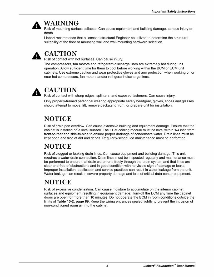
NOTICERisk of drain pan overflow. Can cause extensive building and equipment damage. Ensure that the cabinet is installed on a level surface. The ECM cooling module must be level within 1/4 inch from front-to-rear and side-to-side to ensure proper drainage of condensate water. Drain lines must be kept open and free of dirt and debris. Regularly-scheduled maintenance must be performed.
NOTICERisk of clogged or leaking drain lines. Can cause equipment and building damage. This unit requires a water-drain connection. Drain lines must be inspected regularly and maintenance must be performed to ensure that drain water runs freely through the drain system and that lines are clear and free of obstructions and in good condition with no visible sign of damage or leaks. Improper installation, application and service practices can result in water leakage from the unit. Water leakage can result in severe property damage and loss of critical data-center equipment.
NOTICERisk of excessive condensation. Can cause moisture to accumulate on the interior cabinet surfaces and equipment resulting in equipment damage. Turn-off the ECM any time the cabinet doors are open for more than 10 minutes. Do not operate the ECM in room conditions outside the limits of Table 15-2, page 89. Keep the wiring entrances sealed tightly to prevent the intrusion of non-conditioned room air into the cabinet.
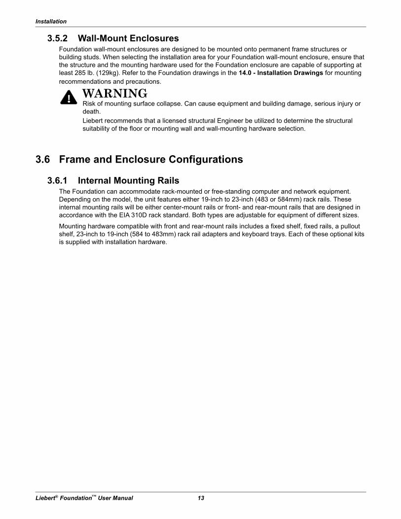
! WARNINGRisk of mounting surface collapse. Can cause equipment and building damage, serious injury or death.
Liebert recommends that a licensed structural Engineer be utilized to determine the structural suitability of the floor or mounting wall and wall-mounting hardware selection.
! CAUTIONRisk of contact with hot surfaces. Can cause injury.
The compressors, fan motors and refrigerant-discharge lines are extremely hot during unit operation. Allow sufficient time for them to cool before working within the BCM or ECM unit cabinets. Use extreme caution and wear protective gloves and arm protection when working on or near hot compressors, fan motors and/or refrigerant-discharge lines.
! CAUTIONRisk of contact with sharp edges, splinters, and exposed fasteners. Can cause injury.
Only properly-trained personnel wearing appropriate safety headgear, gloves, shoes and glasses should attempt to move, lift, remove packaging from, or prepare unit for installation.
Important Safety Instructions
Liebert® Foundation™ User Manual 3
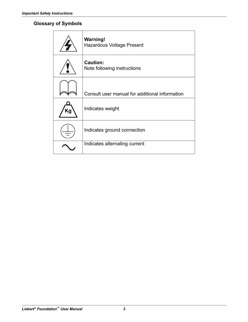
Glossary of Symbols
Warning!Hazardous Voltage Present
Caution:Note following instructions
Consult user manual for additional information
Indicates weight
Indicates ground connection
Indicates alternating current
Introduction
4 Liebert® Foundation™ User Manual
1.0 IntroductionCongratulations on purchasing a Liebert Foundation. The highly versatile Foundation can provide an organized, secure, controlled environment in a single system for your sensitive electronic equipment.
The Foundation is available in a variety of configurations to suit your electronic equipment’s environmental needs. Whether you need a rack to organize your electronic equipment, locking doors for security, a UPS for power protection, and/or an ECM air conditioner to keep your equipment at a constant temperature, the Foundation will provide the level of protection you require.
The Foundation can be upgraded to fit your changing needs as your operations expand and you add more sensitive electronic equipment.
1.1 About this ManualThe Foundation’s flexibility means that a variety of configurations exist for the unit. The various sections cover:
• Frame—The basic setup; relevant to all Foundation configurations.
• Enclosure—The types of doors and side panels, as well as attendant hardware, available as upgrades to accommodate various options.
• Power—The wide selection of Uninterruptible Power Supply (UPS) models and MP Advanced Power Strips available for the Foundation.
• Environmental—Computer-grade environmental conditioning units that may be employed: Environmental Control Module (ECM), Backup Cooling Module (BCM) and FAN Fan Cooling.
• Monitoring—Hardware to collect data about conditions within the Foundation and about its components.
Any or all of the components may be included in your Foundation, depending on the unit’s configuration. If, for example, your Foundation is equipped with an ECM, but no UPS or monitoring equipment, you might want to read the sections on Frames, Enclosures and Environmental, skipping the sections titled Power and Monitoring.
Major Components
Liebert® Foundation™ User Manual 5
2.0 Major ComponentsYou may have any or all of the components discussed in this section, depending on your Foundation configuration.
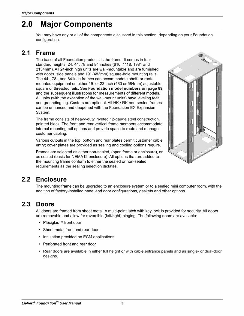
2.1 FrameThe base of all Foundation products is the frame. It comes in four standard heights: 24, 44, 78 and 84 inches (610, 1118, 1981 and 2134mm). All 24-inch high units are wall-mountable and are furnished with doors, side panels and 19" (483mm) square-hole mounting rails. The 44-, 78-, and 84-inch frames can accommodate shelf- or rack-mounted equipment on either 19- or 23-inch (483 or 584mm) adjustable, square or threaded rails. See Foundation model numbers on page 89 and the subsequent illustrations for measurements of different models. All units (with the exception of the wall-mount units) have leveling feet and grounding lug. Casters are optional. All HK / RK non-sealed frames can be enhanced and deepened with the Foundation EX Expansion System.
The frame consists of heavy-duty, riveted 12-gauge steel construction, painted black. The front and rear vertical frame members accommodate internal mounting rail options and provide space to route and manage customer cabling.
Various cutouts in the top, bottom and rear plates permit customer cable entry; cover plates are provided as sealing and cooling options require.
Frames are selected as either non-sealed, (open frame or enclosure), or as sealed (basis for NEMA12 enclosure). All options that are added to the mounting frame conform to either the sealed or non-sealed requirements as the sealing selection dictates.
2.2 EnclosureThe mounting frame can be upgraded to an enclosure system or to a sealed mini computer room, with the addition of factory-installed panel and door configurations, gaskets and other options.
2.3 DoorsAll doors are framed from sheet metal. A multi-point latch with key lock is provided for security. All doors are removable and allow for reversible (left/right) hinging. The following doors are available:
• Plexiglas™ front door
• Sheet metal front and rear door
• Insulation provided on ECM applications
• Perforated front and rear door
• Rear doors are available in either full height or with cable entrance panels and as single- or dual-door designs.
Major Components
6 Liebert® Foundation™ User Manual
2.4 Side PanelsSide panels are fashioned from sheet metal. Special fasteners inside and outside the unit permit removal of all panels for maintenance while preserving internal security during normal operation.
Side panels are available in either solid or vented designs. An insulation option is required for Foundation systems that use ECM cooling. This provides improved thermal and sound insulation.
2.5 Foundation EX Expansion SystemThe Liebert Foundation EX Expansion System and optional accessories add depth to your Foundation to accommodate larger equipment and offer almost unlimited latitude in cable management. Foundation EX Expansion Systems can be factory-installed or field-installed, allowing you to increase the depth of non-sealed Foundation cabinets.
2.6 Power
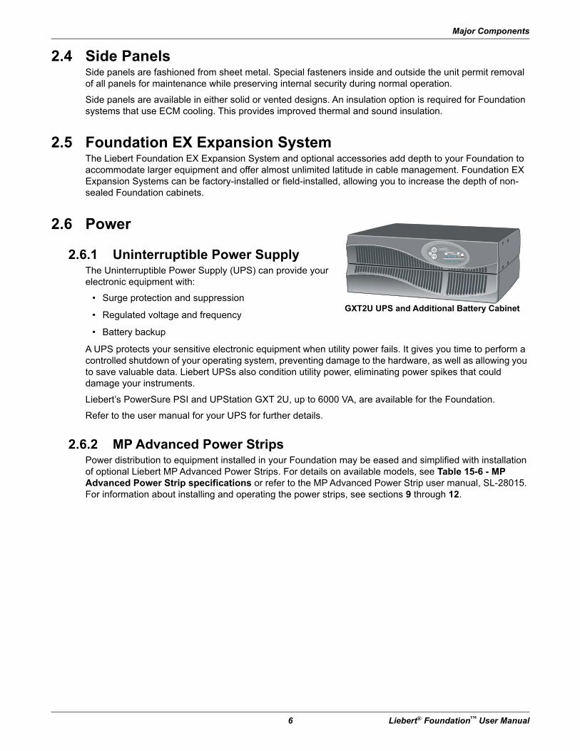
2.6.1 Uninterruptible Power SupplyThe Uninterruptible Power Supply (UPS) can provide your electronic equipment with:
• Surge protection and suppression
• Regulated voltage and frequency
• Battery backup
A UPS protects your sensitive electronic equipment when utility power fails. It gives you time to perform a controlled shutdown of your operating system, preventing damage to the hardware, as well as allowing you to save valuable data. Liebert UPSs also condition utility power, eliminating power spikes that could damage your instruments.
Liebert’s PowerSure PSI and UPStation GXT 2U, up to 6000 VA, are available for the Foundation.
Refer to the user manual for your UPS for further details.
2.6.2 MP Advanced Power StripsPower distribution to equipment installed in your Foundation may be eased and simplified with installation of optional Liebert MP Advanced Power Strips. For details on available models, see Table 15-6 - MP Advanced Power Strip specifications or refer to the MP Advanced Power Strip user manual, SL-28015. For information about installing and operating the power strips, see sections 9 through 12.
GXT2U UPS and Additional Battery Cabinet
+–
UPStation GXT
AC INPUT BATTERY UPS ON BYPASS
Liebert
Major Components
Liebert® Foundation™ User Manual 7
2.7 Environmental
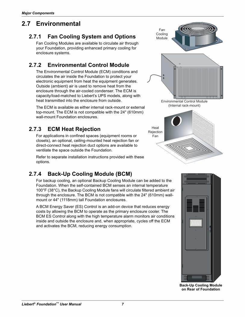
2.7.1 Fan Cooling System and OptionsFan Cooling Modules are available to circulate air through your Foundation, providing enhanced primary cooling for enclosure systems.
2.7.2 Environmental Control ModuleThe Environmental Control Module (ECM) conditions and circulates the air inside the Foundation to protect your electronic equipment from heat the equipment generates. Outside (ambient) air is used to remove heat from the enclosure through the air-cooled condenser. The ECM is capacity/load-matched to Liebert’s UPS models, along with heat transmitted into the enclosure from outside.
The ECM is available as either internal rack-mount or external top-mount. The ECM is not compatible with the 24" (610mm) wall-mount Foundation enclosures.
2.7.3 ECM Heat RejectionFor applications in confined spaces (equipment rooms or closets), an optional, ceiling-mounted heat rejection fan or direct-connect heat rejection duct options are available to ventilate the space outside the Foundation.
Refer to separate installation instructions provided with these options.
2.7.4 Back-Up Cooling Module (BCM)For backup cooling, an optional Backup Cooling Module can be added to the Foundation. When the self-contained BCM senses an internal temperature 100°F (38°C), the Backup Cooling Module fans will circulate filtered ambient air through the enclosure. The BCM is not compatible with the 24" (610mm) wall-mount or 44" (1118mm) tall Foundation enclosures.
A BCM Energy Saver (ES) Control is an add-on device that reduces energy costs by allowing the BCM to operate as the primary enclosure cooler. The BCM ES Control along with the high temperature alarm monitors air conditions inside and outside the enclosure and, when appropriate, cycles off the ECM and activates the BCM, reducing energy consumption.
Fan
Cooling
Module
Environmental Control Module
(Internal rack-mount)
Heat
Rejection
Fan
Back-Up Cooling Module on Rear of Foundation
Major Components
8 Liebert® Foundation™ User Manual
2.8 MonitoringEach monitoring package can be factory-installed and pre-wired or field-installed.
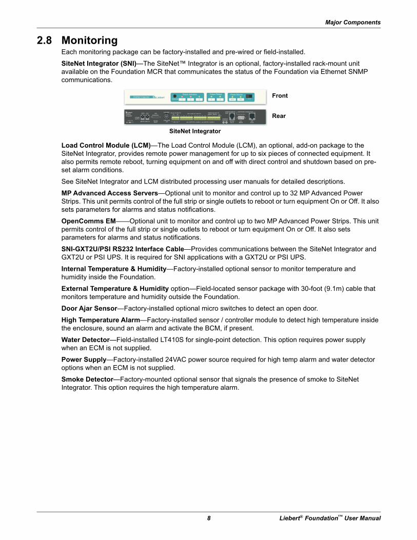
SiteNet Integrator (SNI)—The SiteNet™ Integrator is an optional, factory-installed rack-mount unit available on the Foundation MCR that communicates the status of the Foundation via Ethernet SNMP communications.
Load Control Module (LCM)—The Load Control Module (LCM), an optional, add-on package to the SiteNet Integrator, provides remote power management for up to six pieces of connected equipment. It also permits remote reboot, turning equipment on and off with direct control and shutdown based on pre-set alarm conditions.
See SiteNet Integrator and LCM distributed processing user manuals for detailed descriptions.
MP Advanced Access Servers—Optional unit to monitor and control up to 32 MP Advanced Power Strips. This unit permits control of the full strip or single outlets to reboot or turn equipment On or Off. It also sets parameters for alarms and status notifications.
OpenComms EM——Optional unit to monitor and control up to two MP Advanced Power Strips. This unit permits control of the full strip or single outlets to reboot or turn equipment On or Off. It also sets parameters for alarms and status notifications.
SNI-GXT2U/PSI RS232 Interface Cable—Provides communications between the SiteNet Integrator and GXT2U or PSI UPS. It is required for SNI applications with a GXT2U or PSI UPS.
Internal Temperature & Humidity—Factory-installed optional sensor to monitor temperature and humidity inside the Foundation.
External Temperature & Humidity option—Field-located sensor package with 30-foot (9.1m) cable that monitors temperature and humidity outside the Foundation.
Door Ajar Sensor—Factory-installed optional micro switches to detect an open door.
High Temperature Alarm—Factory-installed sensor / controller module to detect high temperature inside the enclosure, sound an alarm and activate the BCM, if present.
Water Detector—Field-installed LT410S for single-point detection. This option requires power supply when an ECM is not supplied.
Power Supply—Factory-installed 24VAC power source required for high temp alarm and water detector options when an ECM is not supplied.
Smoke Detector—Factory-mounted optional sensor that signals the presence of smoke to SiteNet Integrator. This option requires the high temperature alarm.
SiteNet Integrator
Front
RearR
SiteNetIntegrator
POWERSUPPLY
MAIN AUX UPS DRY-CONTACT INPUTSTEMP/HUM INPUTS
CHASSISGROUND
RS-232RJ-12
STPDB-9S
UTPRJ-45
NETWORK CONNECTIONCONFIGURATIONPORT
ALL OUTPUTS: CLASS 2. ALL INPUTS: CLASS 2.28V, 1A
AUX MOD
C-NC-NO C-NC-NO 1 2 43 5 6 7 8 9 10
RELAY OUTPUTSK1 K2
CIRCULARDIN
RS-232DB-9P
INPUT: 9VDC 1APOWER JACK
MODULE1 MODULE2TEMPSENSOR
(TOKEN RING ONLY)
T H + - T H + -
+
R
MAIN AUX1 21 2 3
Installation
Liebert® Foundation™ User Manual 9
3.0 Installation
3.1 InspectionUpon receiving your Foundation, examine the packaging for any signs of mishandling or damage. If any damage is noted, notify your local Liebert representative and your carrier.
3.2 Required Setup EquipmentThe following tools are required to set up your Foundation:
• pallet jack
• utility knife
• 1/2” (13mm) ratchet or wrench
• 10mm wrench (for adjusting rails)
• hammer
3.3 Electrical RequirementsThis section describes the electrical service requirements for your Foundation system and its options. For the full load amp requirements of each option, please refer to 15.1 - Cooling Systems and 15.2 - Power Systems or the component's user manual.
3.3.1 Environmental Control Module (ECM)If your Foundation is equipped with an ECM, it should be powered from a dedicated electrical circuit.
DO NOT plug the ECM into the optional UPS or into the same input circuit to the UPS.
All 120V/60Hz ECMs are equipped with 9-foot (2.7m) long cords with NEMA 5-15 input plugs.
All 230V/50Hz ECMs are equipped with IEC-C14 plugs.
3.3.2 Backup Cooling Module (BCM)The BCM is an optional, self-contained backup cooling system. If the Foundation is supplied with a UPS and BCM, the BCM is powered from the UPS. All 120V/60Hz BCMs are equipped with 6-foot (1.8m) long cords with NEMA 5-15 input plugs.
All 230V/50Hz ECMs are equipped with IEC-C14 plugs.
3.3.3 FAN CoolingAll 60Hz FAN units are supplied with NEMA 5-15 plugs. All cords are 15 feet (4.6m) long.All 230V/50Hz ECMs are equipped with IEC-C14 plugs.
3.3.4 Uninterruptible Power Supply (UPS)If your Foundation is equipped with a UPS, it will require connection to a dedicated electrical circuit. Review the UPS’s user manual before connecting utility power to the unit.
Installation
10 Liebert® Foundation™ User Manual
3.3.5 MP Advanced Power StripsMP Advanced Power Strips are available in several power ranges. Consult Table 15-6 in 15.0 - Specifications for your model’s power requirements or refer to the MP Advanced Power Strip user manual, SL-28015. For information about installation and operation, see 9.0 - MP Advanced Power Strips—Installation, 10.0 - Using the Liebert MP Advanced Power Strips, 11.0 - Monitoring and Controlling MP Advanced Power Strips with OpenComms EM PDU and 12.0 - Monitoring and Controlling the Liebert MP Advanced Power Strips with the MP Advanced Access Server.
3.4 Unloading the Foundation
Before you start unloading your Foundation, please note the unit weight of your model. Use at least two people when moving the unit. See Tables 15-1, 15-4, and 15-5 for cabinet and cooling-equipment weights.
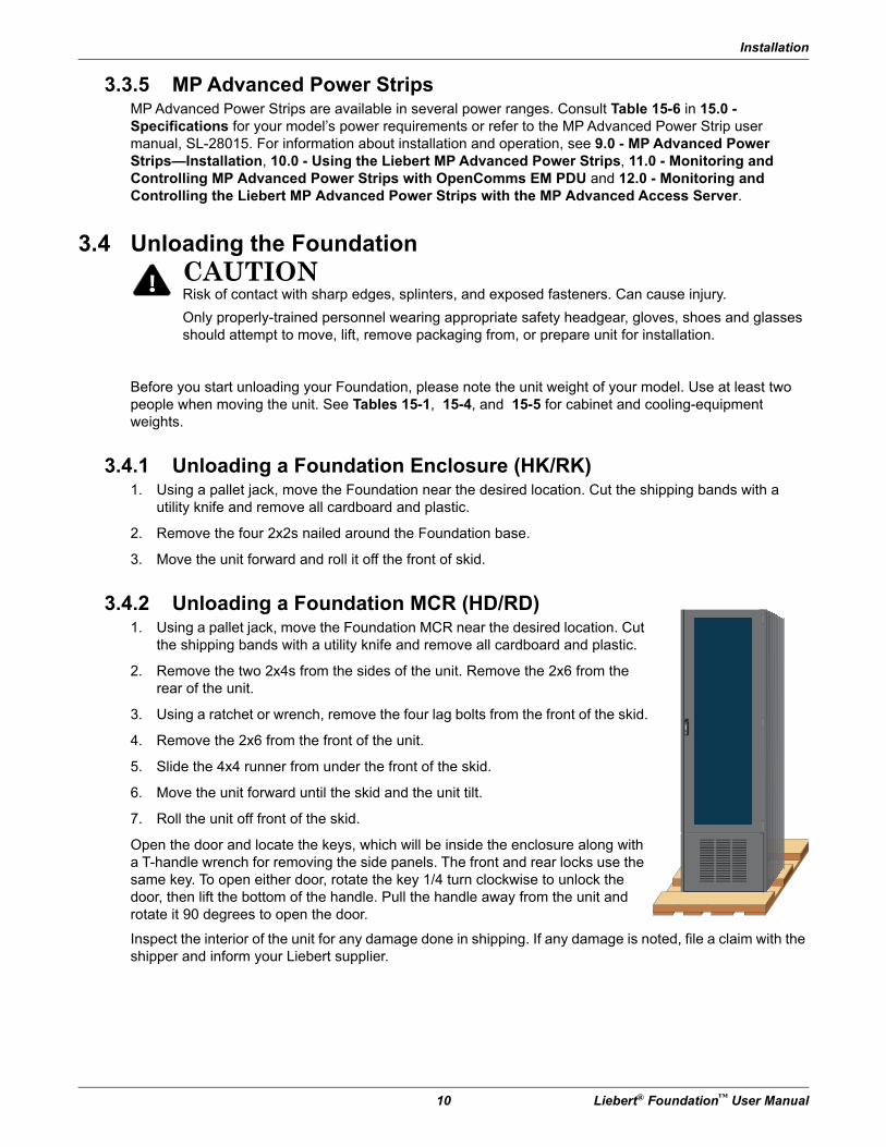
3.4.1 Unloading a Foundation Enclosure (HK/RK)1. Using a pallet jack, move the Foundation near the desired location. Cut the shipping bands with a
utility knife and remove all cardboard and plastic.
2. Remove the four 2x2s nailed around the Foundation base.
3. Move the unit forward and roll it off the front of skid.
3.4.2 Unloading a Foundation MCR (HD/RD)1. Using a pallet jack, move the Foundation MCR near the desired location. Cut
the shipping bands with a utility knife and remove all cardboard and plastic.
2. Remove the two 2x4s from the sides of the unit. Remove the 2x6 from the rear of the unit.
3. Using a ratchet or wrench, remove the four lag bolts from the front of the skid.
4. Remove the 2x6 from the front of the unit.
5. Slide the 4x4 runner from under the front of the skid.
6. Move the unit forward until the skid and the unit tilt.
7. Roll the unit off front of the skid.
Open the door and locate the keys, which will be inside the enclosure along with a T-handle wrench for removing the side panels. The front and rear locks use the same key. To open either door, rotate the key 1/4 turn clockwise to unlock the door, then lift the bottom of the handle. Pull the handle away from the unit and rotate it 90 degrees to open the door.
Inspect the interior of the unit for any damage done in shipping. If any damage is noted, file a claim with the shipper and inform your Liebert supplier.
! CAUTIONRisk of contact with sharp edges, splinters, and exposed fasteners. Can cause injury.
Only properly-trained personnel wearing appropriate safety headgear, gloves, shoes and glasses should attempt to move, lift, remove packaging from, or prepare unit for installation.
Installation
Liebert® Foundation™ User Manual 11
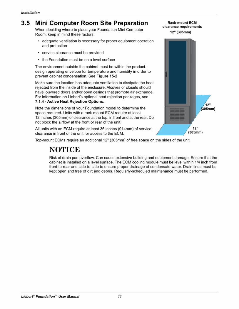
3.5 Mini Computer Room Site PreparationWhen deciding where to place your Foundation Mini Computer Room, keep in mind these factors:
• adequate ventilation is necessary for proper equipment operation and protection
• service clearance must be provided
• the Foundation must be on a level surface
The environment outside the cabinet must be within the product- design operating envelope for temperature and humidity in order to prevent cabinet condensation. See Figure 15-2
Make sure the location has adequate ventilation to dissipate the heat rejected from the inside of the enclosure. Alcoves or closets should have louvered doors and/or open ceilings that promote air exchange. For information on Liebert’s optional heat rejection packages, see 7.1.4 - Active Heat Rejection Options.
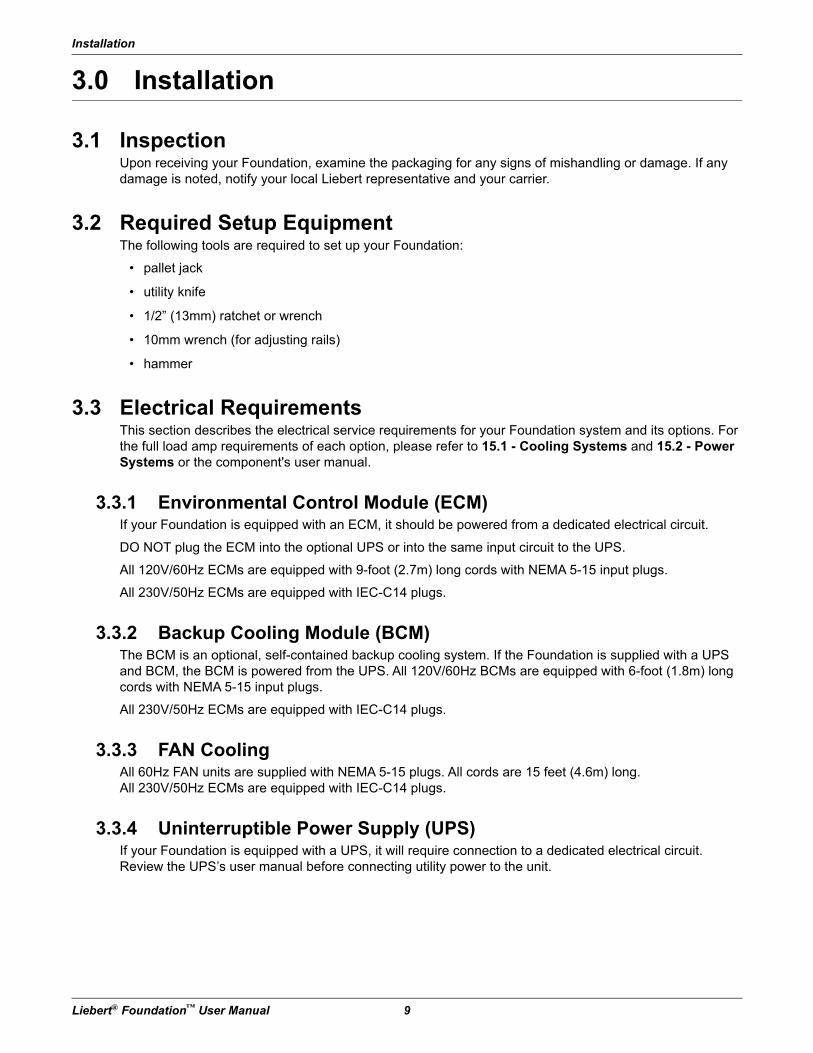
Note the dimensions of your Foundation model to determine the space required. Units with a rack-mount ECM require at least 12 inches (305mm) of clearance at the top, in front and at the rear. Do not block the airflow at the front or rear of the unit.
All units with an ECM require at least 36 inches (914mm) of service clearance in front of the unit for access to the ECM.
Top-mount ECMs require an additional 12" (305mm) of free space on the sides of the unit.
NOTICERisk of drain pan overflow. Can cause extensive building and equipment damage. Ensure that the cabinet is installed on a level surface. The ECM cooling module must be level within 1/4 inch from front-to-rear and side-to-side to ensure proper drainage of condensate water. Drain lines must be kept open and free of dirt and debris. Regularly-scheduled maintenance must be performed.
12" (305mm)
12" (305mm)
12" (305mm)
Rack-mount ECMclearance requirements
Installation
12 Liebert® Foundation™ User Manual
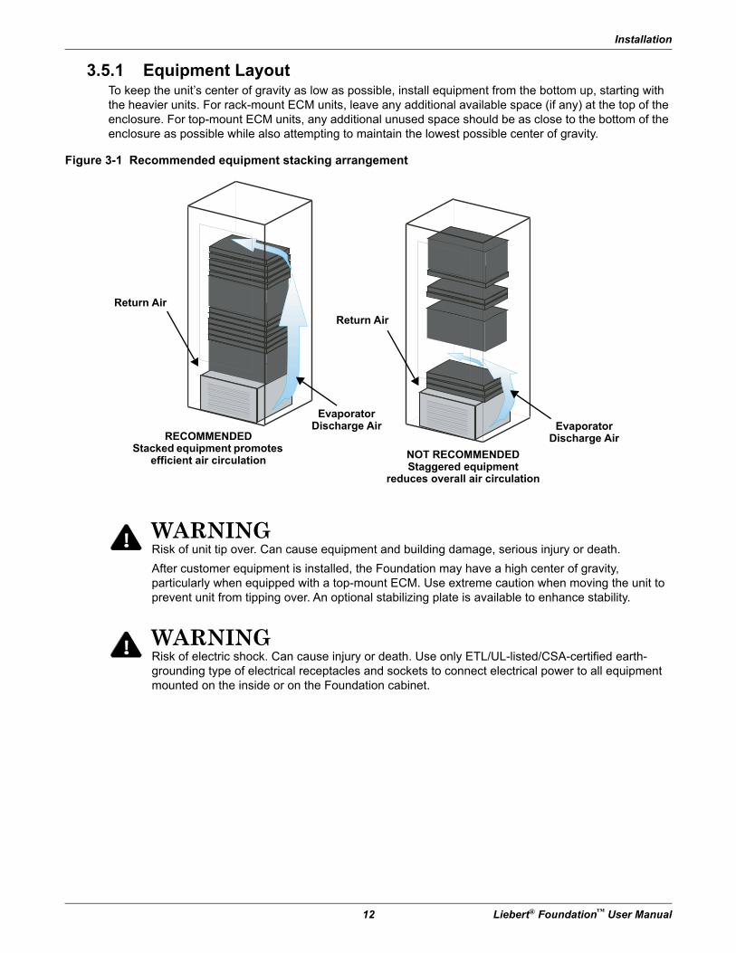
3.5.1 Equipment LayoutTo keep the unit’s center of gravity as low as possible, install equipment from the bottom up, starting with the heavier units. For rack-mount ECM units, leave any additional available space (if any) at the top of the enclosure. For top-mount ECM units, any additional unused space should be as close to the bottom of the enclosure as possible while also attempting to maintain the lowest possible center of gravity.
Figure 3-1 Recommended equipment stacking arrangement
! WARNINGRisk of unit tip over. Can cause equipment and building damage, serious injury or death.
After customer equipment is installed, the Foundation may have a high center of gravity, particularly when equipped with a top-mount ECM. Use extreme caution when moving the unit to prevent unit from tipping over. An optional stabilizing plate is available to enhance stability.
! WARNINGRisk of electric shock. Can cause injury or death. Use only ETL/UL-listed/CSA-certified earth-grounding type of electrical receptacles and sockets to connect electrical power to all equipment mounted on the inside or on the Foundation cabinet.
Return Air
Return Air
RECOMMENDEDStacked equipment promotes
efficient air circulation
Evaporator Discharge Air Evaporator
Discharge Air
NOT RECOMMENDEDStaggered equipment
reduces overall air circulation
Installation
Liebert® Foundation™ User Manual 13
3.5.2 Wall-Mount EnclosuresFoundation wall-mount enclosures are designed to be mounted onto permanent frame structures or building studs. When selecting the installation area for your Foundation wall-mount enclosure, ensure that the structure and the mounting hardware used for the Foundation enclosure are capable of supporting at least 285 lb. (129kg). Refer to the Foundation drawings in the 14.0 - Installation Drawings for mounting recommendations and precautions.
3.6 Frame and Enclosure Configurations
3.6.1 Internal Mounting RailsThe Foundation can accommodate rack-mounted or free-standing computer and network equipment. Depending on the model, the unit features either 19-inch to 23-inch (483 or 584mm) rack rails. These internal mounting rails will be either center-mount rails or front- and rear-mount rails that are designed in accordance with the EIA 310D rack standard. Both types are adjustable for equipment of different sizes.
Mounting hardware compatible with front and rear-mount rails includes a fixed shelf, fixed rails, a pullout shelf, 23-inch to 19-inch (584 to 483mm) rack rail adapters and keyboard trays. Each of these optional kits is supplied with installation hardware.
! WARNINGRisk of mounting surface collapse. Can cause equipment and building damage, serious injury or death.
Liebert recommends that a licensed structural Engineer be utilized to determine the structural suitability of the floor or mounting wall and wall-mounting hardware selection.
Installation
14 Liebert® Foundation™ User Manual
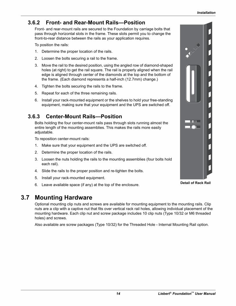
3.6.2 Front- and Rear-Mount Rails—PositionFront- and rear-mount rails are secured to the Foundation by carriage bolts that pass through horizontal slots in the frame. These slots permit you to change the front-to-rear distance between the rails as your application requires.
To position the rails:
1. Determine the proper location of the rails.
2. Loosen the bolts securing a rail to the frame.
3. Move the rail to the desired position, using the angled row of diamond-shaped holes (at right) to get the rail square. The rail is properly aligned when the rail edge is aligned through center of the diamonds at the top and the bottom of the frame. (Each diamond represents a half-inch (12.7mm) change.)
4. Tighten the bolts securing the rails to the frame.
5. Repeat for each of the three remaining rails.
6. Install your rack-mounted equipment or the shelves to hold your free-standing equipment, making sure that your equipment and the UPS are switched off.
3.6.3 Center-Mount Rails—PositionBolts holding the four center-mount rails pass through slots running almost the entire length of the mounting assemblies. This makes the rails more easily adjustable.
To reposition center-mount rails:
1. Make sure that your equipment and the UPS are switched off.
2. Determine the proper location of the rails.
3. Loosen the nuts holding the rails to the mounting assemblies (four bolts hold each rail).
4. Slide the rails to the proper position and re-tighten the bolts.
5. Install your rack-mounted equipment.
6. Leave available space (if any) at the top of the enclosure.
3.7 Mounting HardwareOptional mounting clip nuts and screws are available for mounting equipment to the mounting rails. Clip nuts are a clip with a captive nut that fits over vertical rack rail holes, allowing individual placement of the mounting hardware. Each clip nut and screw package includes 10 clip nuts (Type 10/32 or M6 threaded holes) and screws.
Also available are screw packages (Type 10/32) for the Threaded Hole - Internal Mounting Rail option.
Detail of Rack Rail
Installation
Liebert® Foundation™ User Manual 15
3.8 Door—Remove and ReverseThe doors available for the Foundation are removable for convenience when installing equipment. They also are reversible, enabling you to have the single-door open in a more convenient direction if it is near a wall or other equipment.
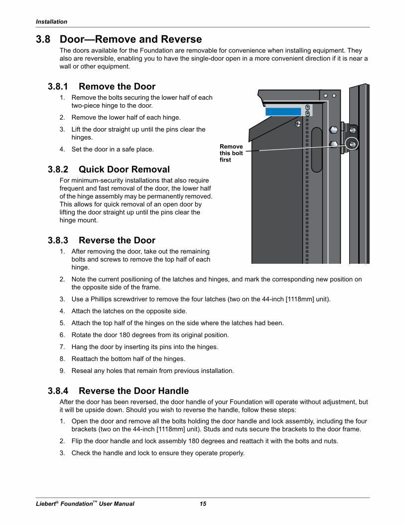
3.8.1 Remove the Door1. Remove the bolts securing the lower half of each
two-piece hinge to the door.
2. Remove the lower half of each hinge.
3. Lift the door straight up until the pins clear the hinges.
4. Set the door in a safe place.
3.8.2 Quick Door RemovalFor minimum-security installations that also require frequent and fast removal of the door, the lower half of the hinge assembly may be permanently removed. This allows for quick removal of an open door by lifting the door straight up until the pins clear the hinge mount.
3.8.3 Reverse the Door1. After removing the door, take out the remaining
bolts and screws to remove the top half of each hinge.
2. Note the current positioning of the latches and hinges, and mark the corresponding new position on the opposite side of the frame.
3. Use a Phillips screwdriver to remove the four latches (two on the 44-inch [1118mm] unit).
4. Attach the latches on the opposite side.
5. Attach the top half of the hinges on the side where the latches had been.
6. Rotate the door 180 degrees from its original position.
7. Hang the door by inserting its pins into the hinges.
8. Reattach the bottom half of the hinges.
9. Reseal any holes that remain from previous installation.
3.8.4 Reverse the Door HandleAfter the door has been reversed, the door handle of your Foundation will operate without adjustment, but it will be upside down. Should you wish to reverse the handle, follow these steps:
1. Open the door and remove all the bolts holding the door handle and lock assembly, including the four brackets (two on the 44-inch [1118mm] unit). Studs and nuts secure the brackets to the door frame.
2. Flip the door handle and lock assembly 180 degrees and reattach it with the bolts and nuts.
3. Check the handle and lock to ensure they operate properly.
Remove this bolt first
Installation
16 Liebert® Foundation™ User Manual
3.9 Side Panels—Remove and ReplaceFoundation side panels are simple to remove and replace, making it easier to install equipment. Panel removal also improves access for maintaining or replacing equipment.
3.9.1 Remove a Panel1. Inside the Foundation, locate the two security bolts in each side panel. (The security bolts are about
halfway up the side of the panels; one is near the front edge of the panel and the other near the rear.)
2. Remove the bolts with a 10mm wrench.
3. Locate the four panel retainers on the outside of the Foundation panel. There is one retainer in each corner of the panel.
4. Using the factory-supplied T-handle Allen wrench, turn the panel retainers 90 degrees counterclockwise.
5. Lift the panel off the lip at the bottom of the Foundation and set it in a safe location.
3.9.2 Replace a Panel1. Set the panel on the lip at the bottom of the Foundation frame.
2. Using the factory-supplied T-handle Allen wrench, turn each of the four panel retainers clockwise 90-degrees.
3. For additional security, insert and tighten the two security bolts inside the Foundation, using a 10mm wrench.
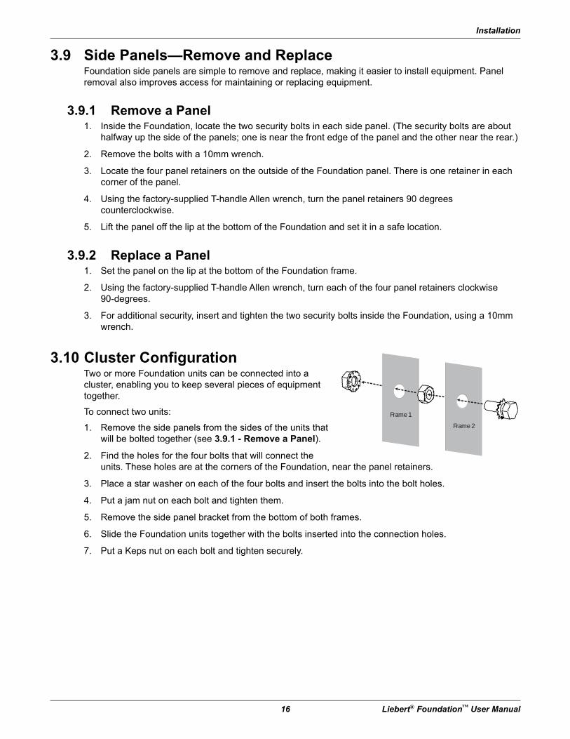
3.10 Cluster ConfigurationTwo or more Foundation units can be connected into a cluster, enabling you to keep several pieces of equipment together.
To connect two units:
1. Remove the side panels from the sides of the units that will be bolted together (see 3.9.1 - Remove a Panel).
2. Find the holes for the four bolts that will connect the units. These holes are at the corners of the Foundation, near the panel retainers.
3. Place a star washer on each of the four bolts and insert the bolts into the bolt holes.
4. Put a jam nut on each bolt and tighten them.
5. Remove the side panel bracket from the bottom of both frames.
6. Slide the Foundation units together with the bolts inserted into the connection holes.
7. Put a Keps nut on each bolt and tighten securely.
Frame 1
Frame 2
Foundation EX—Expansion System
Liebert® Foundation™ User Manual 17
4.0 Foundation EX—Expansion SystemThe Foundation EX Expansion System is a flexible solution to rack-enclosure space and cable problems utilizing a patent pending “Expansion Channel” platform to provide adaptive space for airflow, equipment and cabling support. Cable and equipment mounting options are available to adapt to changing requirements.
EX Expansion Channels include a set (left / right) of sheet metal channels mounted to the front and / or rear of an HK or RK (non-sealed) mounting frame. Available in nominal depths of 2", 4", or 6" (1U, 2U or 3U horizontal space), the EX Expansion Channel allows for creation of multiple frame depths. Specialized cutouts are provided to support all EX cable and equipment management options.
EX Expansion Channel top/bottom entrances are available with 2 sets (top / bottom) of EX Cable Management Channels (EX-CMCs) providing cable management into and out of the EX Expansion Channels. The EX-CMCs are sized to fit the associated EX Expansion Channel (1, 2 or 3U).
4.1 InstallationBefore beginning, read all the installation instructions and familiarize yourself with the EX components to be installed. Gather the needed tools and EX parts.
Needed tools are:
• M10 nut driver / wrench or 1/4” ratchet with M10 socket
• Phillips screwdriver
4.1.1 Installing EX Components on a Single FoundationTo install your Liebert EX Expansion System on either the front or rear of the Foundation:
1. Remove the front or rear door, access panels and their hardware from the Foundation (see 3.8 - Door—Remove and Reverse).
2. Attach either left or right EX Expansion Channel assembly as shown in Figure 4-2.
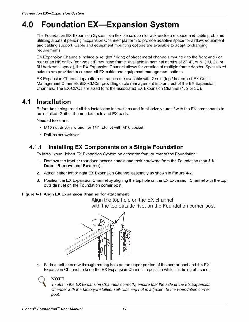
3. Position the EX Expansion Channel by aligning the top hole on the EX Expansion Channel with the top outside rivet on the Foundation corner post.
Figure 4-1 Align EX Expansion Channel for attachment
4. Slide a bolt or screw through mating hole on the upper portion of the corner post and the EX Expansion Channel to keep the EX Expansion Channel in position while it is being attached.
NOTETo attach the EX Expansion Channels correctly, ensure that the side of the EX Expansion Channel with the factory-installed, self-clinching nut is adjacent to the Foundation corner post.
Align the top hole on the EX channel
with the top outside rivet on the Foundation corner post
Foundation EX—Expansion System
18 Liebert® Foundation™ User Manual
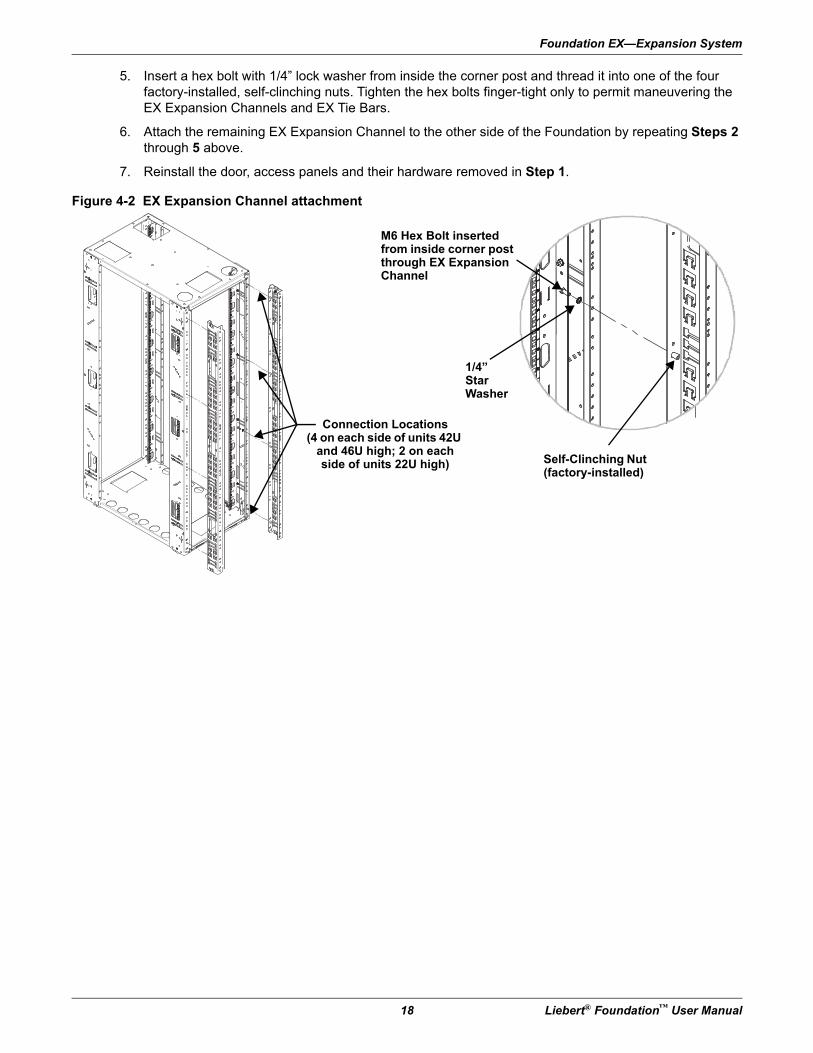
5. Insert a hex bolt with 1/4” lock washer from inside the corner post and thread it into one of the four factory-installed, self-clinching nuts. Tighten the hex bolts finger-tight only to permit maneuvering the EX Expansion Channels and EX Tie Bars.
6. Attach the remaining EX Expansion Channel to the other side of the Foundation by repeating Steps 2 through 5 above.
7. Reinstall the door, access panels and their hardware removed in Step 1.
Figure 4-2 EX Expansion Channel attachment
Connection Locations(4 on each side of units 42U
and 46U high; 2 on each side of units 22U high)
M6 Hex Bolt inserted from inside corner post through EX Expansion Channel
1/4”Star Washer
Self-Clinching Nut (factory-installed)
Foundation EX—Expansion System
Liebert® Foundation™ User Manual 19
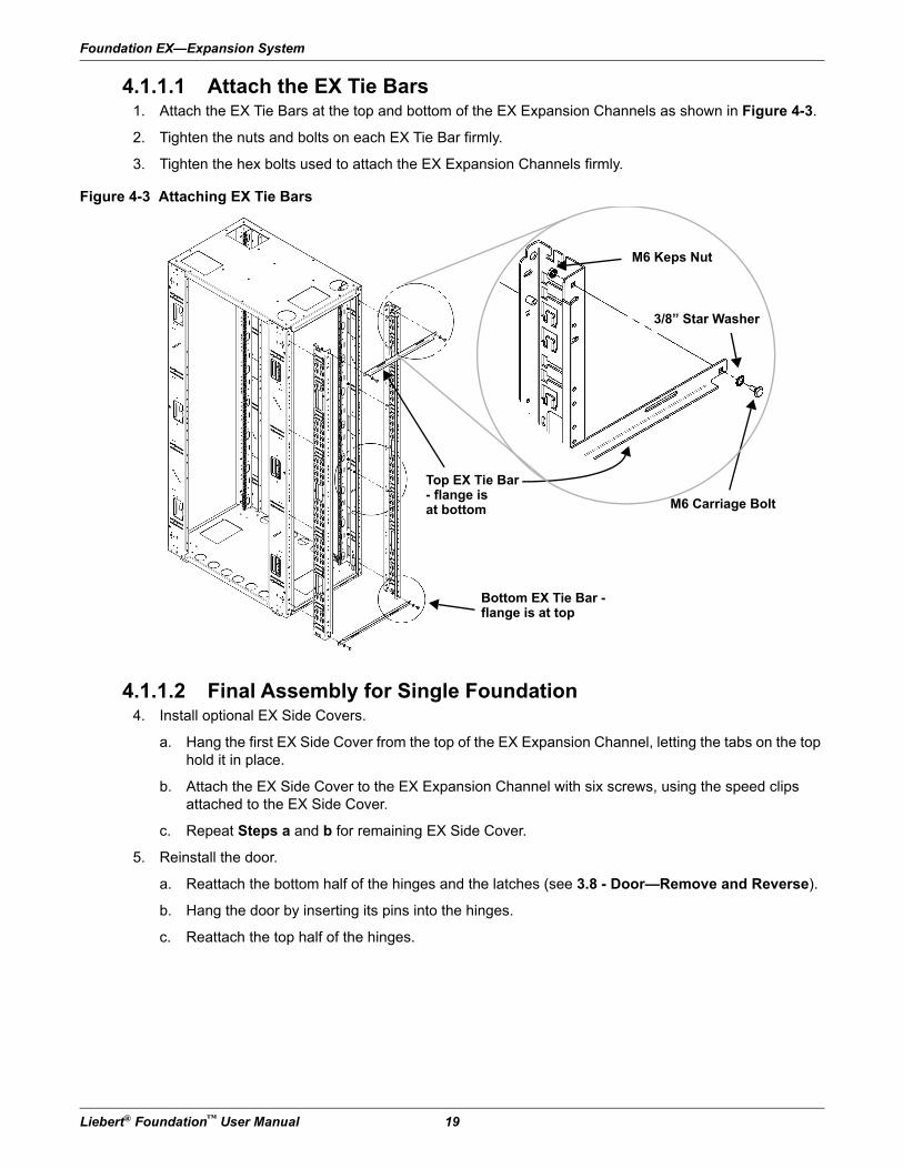
4.1.1.1 Attach the EX Tie Bars1. Attach the EX Tie Bars at the top and bottom of the EX Expansion Channels as shown in Figure 4-3.
2. Tighten the nuts and bolts on each EX Tie Bar firmly.
3. Tighten the hex bolts used to attach the EX Expansion Channels firmly.
Figure 4-3 Attaching EX Tie Bars
4.1.1.2 Final Assembly for Single Foundation4. Install optional EX Side Covers.
a. Hang the first EX Side Cover from the top of the EX Expansion Channel, letting the tabs on the top hold it in place.
b. Attach the EX Side Cover to the EX Expansion Channel with six screws, using the speed clips attached to the EX Side Cover.
c. Repeat Steps a and b for remaining EX Side Cover.
5. Reinstall the door.
a. Reattach the bottom half of the hinges and the latches (see 3.8 - Door—Remove and Reverse).
b. Hang the door by inserting its pins into the hinges.
c. Reattach the top half of the hinges.
M6 Keps Nut
3/8” Star Washer
Bottom EX Tie Bar - flange is at top
M6 Carriage Bolt
Top EX Tie Bar - flange isat bottom
Foundation EX—Expansion System
20 Liebert® Foundation™ User Manual
4.1.2 Stacking EX Expansion ChannelsUp to two sets of EX Expansion Channels may stacked on the front and/or rear of a Foundation frame. For example, a 3U EX Expansion Channel could be added to the rear of a Foundation, and a 2U EX Expansion Channel stacked onto the 3U EX Expansion Channel. Even front-to-rear distribution of weight is required when stacking EX Expansion Channels. The user must take steps to ensure that the weight distribution of equipment yields stability to prevent the Foundation from tipping over.
! WARNINGRisk of mounting surface collapse. Can cause equipment and building damage, serious injury or death.
Liebert recommends that a licensed structural Engineer be utilized to determine the structural suitability of the floor or mounting wall and wall-mounting hardware selection.
Installer must ensure that the mounting surface can support the loaded cabinet weight.
! WARNINGRisk of unit tip over. Can cause equipment and building damage, serious injury or death.
After customer equipment is installed, the Foundation may have a high center of gravity, particularly when equipped with a top-mount ECM. Use extreme caution when moving the unit to prevent unit from tipping over. An optional stabilizing plate is available to enhance stability.
Refer to Figure 3-1 for recommended equipment arrangement.
Foundation EX—Expansion System
Liebert® Foundation™ User Manual 21
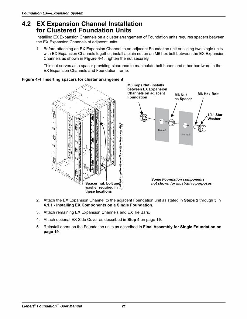
4.2 EX Expansion Channel Installation for Clustered Foundation UnitsInstalling EX Expansion Channels on a cluster arrangement of Foundation units requires spacers between the EX Expansion Channels of adjacent units.
1. Before attaching an EX Expansion Channel to an adjacent Foundation unit or sliding two single units with EX Expansion Channels together, install a plain nut on an M6 hex bolt between the EX Expansion Channels as shown in Figure 4-4. Tighten the nut securely.
This nut serves as a spacer providing clearance to manipulate bolt heads and other hardware in the EX Expansion Channels and Foundation frame.
Figure 4-4 Inserting spacers for cluster arrangement
2. Attach the EX Expansion Channel to the adjacent Foundation unit as stated in Steps 2 through 3 in 4.1.1 - Installing EX Components on a Single Foundation.
3. Attach remaining EX Expansion Channels and EX Tie Bars.
4. Attach optional EX Side Cover as described in Step 4 on page 19.
5. Reinstall doors on the Foundation units as described in Final Assembly for Single Foundation on page 19.
Frame 1
Frame 2
M6 Keps Nut (installs between EX Expansion Channels on adjacent Foundation
Spacer nut, bolt and washer required in these locations
Some Foundation componentsnot shown for illustrative purposes
M6 Nutas Spacer
M6 Hex Bolt
1/4” Star Washer
Foundation EX—Expansion System
22 Liebert® Foundation™ User Manual
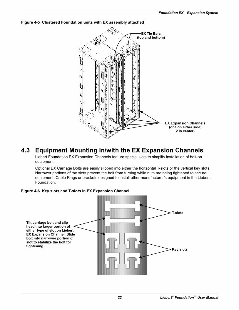
Figure 4-5 Clustered Foundation units with EX assembly attached
4.3 Equipment Mounting in/with the EX Expansion ChannelsLiebert Foundation EX Expansion Channels feature special slots to simplify installation of bolt-on equipment.
Optional EX Carriage Bolts are easily slipped into either the horizontal T-slots or the vertical key slots. Narrower portions of the slots prevent the bolt from turning while nuts are being tightened to secure equipment, Cable Rings or brackets designed to install other manufacturer’s equipment in the Liebert Foundation.
Figure 4-6 Key slots and T-slots in EX Expansion Channel
EX Expansion Channels(one on either side;
2 in center)
EX Tie Bars(top and bottom)
Tilt carriage bolt and slip head into larger portion of either type of slot on Liebert EX Expansion Channel. Slide bolt into narrower portion of slot to stabilize the bolt for tightening.
T-slots
Key slots
Foundation EX—Expansion System
Liebert® Foundation™ User Manual 23
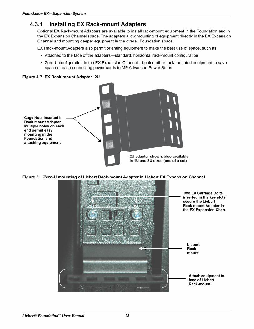
4.3.1 Installing EX Rack-mount AdaptersOptional EX Rack-mount Adapters are available to install rack-mount equipment in the Foundation and in the EX Expansion Channel space. The adapters allow mounting of equipment directly in the EX Expansion Channel and mounting deeper equipment in the overall Foundation space.
EX Rack-mount Adapters also permit orienting equipment to make the best use of space, such as:
• Attached to the face of the adapters—standard, horizontal rack-mount configuration
• Zero-U configuration in the EX Expansion Channel—behind other rack-mounted equipment to save space or ease connecting power cords to MP Advanced Power Strips
Figure 4-7 EX Rack-mount Adapter- 2U
Figure 5 Zero-U mounting of Liebert Rack-mount Adapter in Liebert EX Expansion Channel
Cage Nuts inserted inRack-mount AdapterMultiple holes on each end permit easy mounting in theFoundation andattaching equipment
2U adapter shown; also available in 1U and 3U sizes (one of a set)
Two EX Carriage Bolts inserted in the key slots secure the LiebertRack-mount Adapter in the EX Expansion Chan-
Liebert Rack-mount
Attach equipment to face of Liebert Rack-mount
Foundation EX—Expansion System
24 Liebert® Foundation™ User Manual
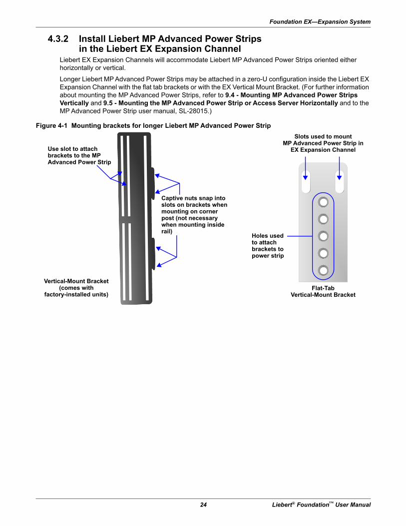
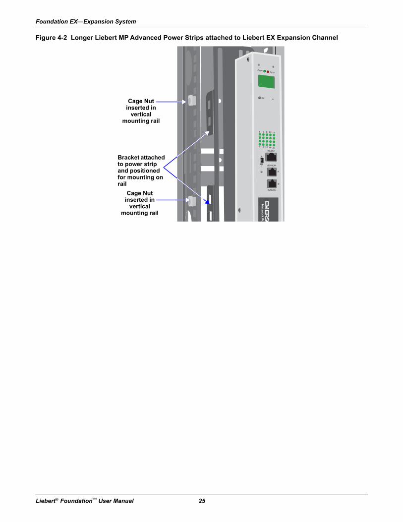
4.3.2 Install Liebert MP Advanced Power Strips in the Liebert EX Expansion Channel
Liebert EX Expansion Channels will accommodate Liebert MP Advanced Power Strips oriented either horizontally or vertical.
Longer Liebert MP Advanced Power Strips may be attached in a zero-U configuration inside the Liebert EX Expansion Channel with the flat tab brackets or with the EX Vertical Mount Bracket. (For further information about mounting the MP Advanced Power Strips, refer to 9.4 - Mounting MP Advanced Power Strips Vertically and 9.5 - Mounting the MP Advanced Power Strip or Access Server Horizontally and to the MP Advanced Power Strip user manual, SL-28015.)
Figure 4-1 Mounting brackets for longer Liebert MP Advanced Power Strip
Flat-TabVertical-Mount Bracket
Slots used to mount MP Advanced Power Strip in
EX Expansion Channel
Holes used to attach brackets to power strip
Use slot to attachbrackets to the MP Advanced Power Strip
Captive nuts snap into slots on brackets when mounting on corner post (not necessary when mounting inside rail)
Vertical-Mount Bracket(comes with
factory-installed units)
Foundation EX—Expansion System
Liebert® Foundation™ User Manual 25
Figure 4-2 Longer Liebert MP Advanced Power Strips attached to Liebert EX Expansion Channel
PWRALM
SEL
1
B
C
A
B
SENSOR
INPUTS
5 9 13 17
4 8 12 16 20
RS-232
EM
ER
SO
Ne
two
rk P
o
Cage Nut inserted in
vertical mounting rail
Bracket attached to power strip and positioned for mounting on rail
Cage Nut inserted in
vertical mounting rail
Foundation EX—Expansion System
26 Liebert® Foundation™ User Manual
4.3.3 Install Internal Mounting Rails in the EX Expansion ChannelThe Internal Mounting Rails attached to the Foundation’s frame may be relocated to the Liebert EX Expansion Channels to accommodate deeper equipment.
Before beginning to move the Internal Mounting Rails, check the equipment's dimensions and determine the rails’ mounting position in the channel (see 3.6.2 - Front- and Rear-Mount Rails—Position).
Support or remove any equipment attached to the Internal Mounting Rail being moved into a Liebert EX Expansion Channel.
Remove the mounting rails, supporting or removing equipment as required. The rails are secured at the factory to the frame with carriage bolts at the top and bottom of each rail. After removing or supporting equipment, remove the rails from the Foundation Frame.
Position the rails in the Liebert EX Expansion Channels and secure them by inserting EX Carriage Bolts into the T-slots in the EX Expansion Channel. T-slots in the EX Expansion Channel match mounting holes in the vertical mounting rails. Secure the vertical mounting rails with the EX Carriage Bolts and nuts. Tighten the nuts securely.
NOTICERisk of improper installation of the internal mounting rails. Can cause equipment damage.
The internal mounting rails are load-bearing and must be securely fastened to the Liebert EX Expansion Channel.
! WARNINGRisk of unit tip over. Can cause equipment and building damage, serious injury or death.
After customer equipment is installed, the Foundation may have a high center of gravity, particularly when equipped with a top-mount ECM. Use extreme caution when moving the unit to prevent unit from tipping over. An optional stabilizing plate is available to enhance stability.
Equipment should always be loaded into the Foundation cabinets starting at the bottom and sequentially moving upward to keep the center of gravity as low as possible.
Refer to Figure 3-1 for the recommended equipment arrangement.
General Cable Management Options
Liebert® Foundation™ User Manual 27
5.0 General Cable Management Options
5.1 Cable ManagementOnce your equipment has been installed, you are ready to connect cables for power and communication. Before making any connections, check the equipment to ensure that all power switches are in the OFF position.
Numerous cable entrances and management provisions are built into the various Foundation configurations to ease cable installation.
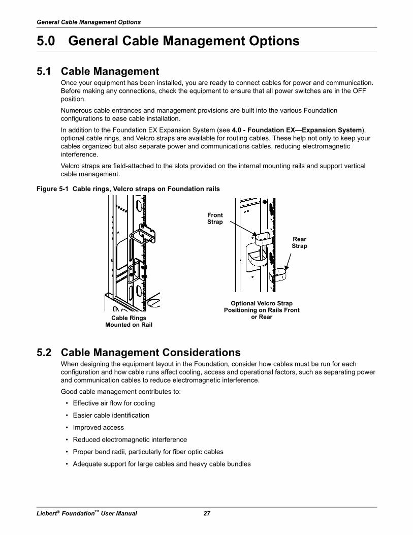
In addition to the Foundation EX Expansion System (see 4.0 - Foundation EX—Expansion System), optional cable rings, and Velcro straps are available for routing cables. These help not only to keep your cables organized but also separate power and communications cables, reducing electromagnetic interference.
Velcro straps are field-attached to the slots provided on the internal mounting rails and support vertical cable management.
Figure 5-1 Cable rings, Velcro straps on Foundation rails
5.2 Cable Management ConsiderationsWhen designing the equipment layout in the Foundation, consider how cables must be run for each configuration and how cable runs affect cooling, access and operational factors, such as separating power and communication cables to reduce electromagnetic interference.
Good cable management contributes to:
• Effective air flow for cooling
• Easier cable identification
• Improved access
• Reduced electromagnetic interference
• Proper bend radii, particularly for fiber optic cables
• Adequate support for large cables and heavy cable bundles
Cable Rings Mounted on Rail
Optional Velcro StrapPositioning on Rails Front
or Rear
Front Strap
Rear Strap
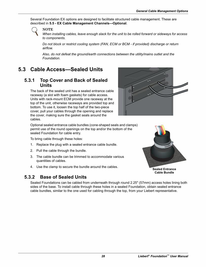
General Cable Management Options
28 Liebert® Foundation™ User Manual
Several Foundation EX options are designed to facilitate structured cable management. These are described in 5.5 - EX Cable Management Channels—Optional.
5.3 Cable Access—Sealed Units
5.3.1 Top Cover and Back of Sealed Units
The back of the sealed unit has a sealed entrance cable raceway (a slot with foam gaskets) for cable access. Units with rack-mount ECM provide one raceway at the top of the unit, otherwise raceways are provided top and bottom. To use it, loosen the top half of the two-piece cover, pull your cables through the opening and replace the cover, making sure the gasket seals around the cables.
Optional sealed entrance cable bundles (cone-shaped seals and clamps) permit use of the round openings on the top and/or the bottom of the sealed Foundation for cable entry.
To bring cable through these holes:
1. Replace the plug with a sealed entrance cable bundle.
2. Pull the cable through the bundle.
3. The cable bundle can be trimmed to accommodate various quantities of cables.
4. Use the clamp to secure the bundle around the cables.
5.3.2 Base of Sealed UnitsSealed Foundations can be cabled from underneath through round 2.25" (57mm) access holes lining both sides of the base. To install cable through these holes in a sealed Foundation, obtain sealed entrance cable bundles, similar to the one used for cabling through the top, from your Liebert representative.
NOTEWhen installing cables, leave enough slack for the unit to be rolled forward or sideways for access to components.
Do not block or restrict cooling system (FAN, ECM or BCM - if provided) discharge or return airflow.
Also, do not defeat the ground/earth connections between the utility/mains outlet and the Foundation.
Sealed EntranceCable Bundle
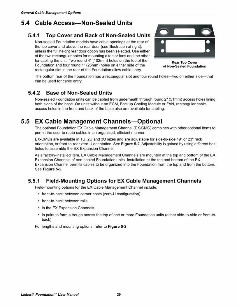
General Cable Management Options
Liebert® Foundation™ User Manual 29
5.4 Cable Access—Non-Sealed Units
5.4.1 Top Cover and Back of Non-Sealed UnitsNon-sealed Foundation models have cable openings at the rear of the top cover and above the rear door (see illustration at right), unless the full height rear door option has been selected. Use either of the two rectangular holes for mounting a fan or fans and the other for cabling the unit. Two round 4" (102mm) holes on the top of the Foundation and four round 1" (25mm) holes on either side of the rectangular slot in the rear of the Foundation allow cable entry.
The bottom rear of the Foundation has a rectangular slot and four round holes—two on either side—that can be used for cable entry.
5.4.2 Base of Non-Sealed UnitsNon-sealed Foundation units can be cabled from underneath through round 2" (51mm) access holes lining both sides of the base. On units without an ECM, Backup Cooling Module or FAN, rectangular cable-access holes in the front and back of the base also are available for cabling.
5.5 EX Cable Management Channels—OptionalThe optional Foundation EX Cable Management Channel (EX-CMC) combines with other optional items to permit the user to route cables in an organized, efficient manner.
EX-CMCs are available in 1U, 2U and 3U sizes and are adjustable for side-to-side 19" or 23" rack orientation, or front-to-rear zero-U orientation. See Figure 5-2. Adjustability is gained by using different bolt holes to assemble the EX Expansion Channel.
As a factory-installed item, EX Cable Management Channels are mounted at the top and bottom of the EX Expansion Channels of non-sealed Foundation units. Installation at the top and bottom of the EX Expansion Channel permits cables to be organized into the Foundation from the top and from the bottom. See Figure 5-2.
5.5.1 Field-Mounting Options for EX Cable Management ChannelsField-mounting options for the EX Cable Management Channel include:
• front-to-back between corner posts (zero-U configuration)
• front-to-back between rails
• in the EX Expansion Channels
• in pairs to form a trough across the top of one or more Foundation units (either side-to-side or front-to-back)
For lengths and mounting options, refer to Figure 5-2.
Rear Top Coverof Non-Sealed Foundation
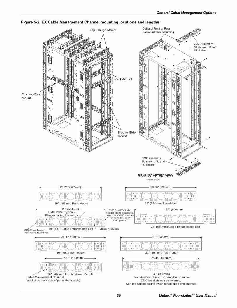
General Cable Management Options
30 Liebert® Foundation™ User Manual
Figure 5-2 EX Cable Management Channel mounting locations and lengths
19" (483) Top Trough
19" (483) Cable Entrance and Exit23" (584mm) Cable Entrance and Exit
19" (483mm) Rack-Mount
20.75" (527mm)
23" (584mm)CMC Panel Typical -
Flanges facing toward you
CMC Panel Typical -
Flanges facing toward you.
CMC Panel Typical -
Flanges facing toward you.
Long tabs of CMC brackets
fit inside flanges of
CMC panels.
Typical 4 places
23" (584mm) Rack-Mount
23" (584mm) Top Trough
25.44" (646mm)
27" (686mm)
27" (686mm)
38" (965mm)
Front-to-Rear, Zero-U, Closed-End Channel
CMC brackets can be inverted,
with the flanges facing away, for an open-end channel.
23.56" (598mm)
23.56" (598mm)
30" (762mm) Front-to-Rear, Zero U
17.44" (443mm)
Cable Management Channel
bracket on back side of panel (both ends)
Top Trough Mount
Rack-Mount
Side-to-Side
Mount
Front-to-Rear
Mount
REAR ISOMETRIC VIEW19" RACK SHOWN
Optional Front or Rear
Cable Entrance Mounting
CMC Assembly
2U shown; 1U and
3U similar
CMC Assembly
2U shown; 1U and
3U similar
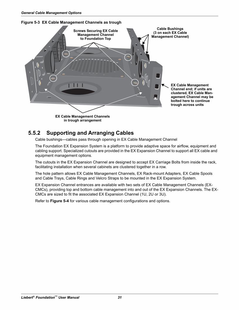
General Cable Management Options
Liebert® Foundation™ User Manual 31
Figure 5-3 EX Cable Management Channels as trough
5.5.2 Supporting and Arranging CablesCable bushings—cables pass through opening in EX Cable Management Channel
The Foundation EX Expansion System is a platform to provide adaptive space for airflow, equipment and cabling support. Specialized cutouts are provided in the EX Expansion Channel to support all EX cable and equipment management options.
The cutouts in the EX Expansion Channel are designed to accept EX Carriage Bolts from inside the rack, facilitating installation when several cabinets are clustered together in a row.
The hole pattern allows EX Cable Management Channels, EX Rack-mount Adapters, EX Cable Spools and Cable Trays, Cable Rings and Velcro Straps to be mounted in the EX Expansion System.
EX Expansion Channel entrances are available with two sets of EX Cable Management Channels (EX-CMCs), providing top and bottom cable management into and out of the EX Expansion Channels. The EX-CMCs are sized to fit the associated EX Expansion Channel (1U, 2U or 3U).
Refer to Figure 5-4 for various cable management configurations and options.
EX Cable Management Channelsin trough arrangement
Screws Securing EX Cable Management Channel
to Foundation Top
Cable Bushings(3 on each EX Cable
Management Channel)
EX Cable Management Channel end; if units are clustered, EX Cable Man-agement Channel may be bolted here to continue trough across units
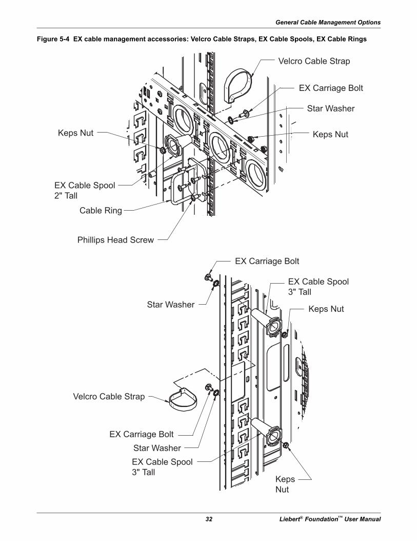
General Cable Management Options
32 Liebert® Foundation™ User Manual
Figure 5-4 EX cable management accessories: Velcro Cable Straps, EX Cable Spools, EX Cable Rings
Keps Nut
Keps Nut
Keps
Nut
Keps Nut
EX Carriage Bolt
EX Carriage Bolt
EX Carriage Bolt
Velcro Cable Strap
Velcro Cable Strap
Star Washer
Star Washer
Star Washer
EX Cable Spool
3" Tall
EX Cable Spool
2" Tall
EX Cable Spool
3" Tall
Cable Ring
Phillips Head Screw
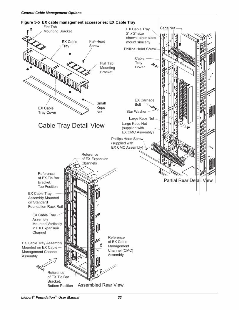
General Cable Management Options
Liebert® Foundation™ User Manual 33
Figure 5-5 EX cable management accessories: EX Cable Tray
Cage NutEX Cable Tray
2” x 2” size
shown; other sizes
mount similarly
Cable
Tray
Cover
EX Carriage
Bolt
Star Washer
Large Keps Nut
(supplied with
EX CMC Assembly)
Phillips Head Screw
Phillips Head Screw
(supplied with
EX CMC Assembly)
Partial Rear Detail View
Large Keps Nut
Cable Tray Detail View
EX Cable
Tray
EX Cable
Tray Cover
Flat-Head
Screw
Flat Tab
Mounting
Bracket
Flat Tab
Mounting Bracket
Small
Keps
Nut
REAR
Reference
of EX Expansion
Channels
Reference
of EX Tie Bar
Bracket,
Top Position
Reference
of EX Tie Bar
Bracket,
Bottom Position Assembled Rear View
Reference
of EX Cable
Management
Channel (CMC)
Assembly
EX Cable Tray
Assembly
Mounted Vertically
in EX Expansion
Channel
EX Cable Tray Assembly
Mounted on EX Cable
Management Channel
Assembly
EX Cable Tray
Assembly Mounted
on Standard
Foundation Rack Rail
Startup
34 Liebert® Foundation™ User Manual
6.0 StartupBefore plugging in your electronic equipment, make sure that all power switches are in the OFF position.
Be certain there are no obstructions, wire bundles, manuals, trash, etc., in front of or on either side of the ECM, if your unit is so equipped. Make sure all doors are shut and sealed properly. Plug the Environmental Control Module (ECM) into a dedicated utility circuit.
• ECM's evaporator fan will begin to circulate air inside the enclosure as soon as power is supplied and will operate continuously.
• The compressor in the ECM is controlled by a thermostat located in the rear left corner of the ECM. This thermostat is factory-set and does not require adjustment. If the setting is changed, contact Liebert Technical Support for assistance.
• The compressor in the Environmental Control Module will shut down if the ECM return air temperature drops below approximately 75°F (18°C). The evaporator fan will continue to circulate internal cabinet air throughout the sealed enclosure. The compressor will resume operating when the FoundationFoundation ECM return air rises above approximately 75°F (18°C).
• Refer to the UPS manual for preparation for startup, details of UPS operation and the meaning of LED indicators. After you have complied with the manual’s instructions, turn on the UPS. Check the UPS’ indicators. If the UPS’s status is normal, proceed with the next step.
• Turn on your computer and network equipment.
NOTEThe UPS’s batteries may require recharging before it can fully supply your equipment’s power needs for the rated time if utility power fails.
To charge the UPS batteries before using the unit, you can apply power to the UPS module while you are installing your equipment or while making adjustments.
NOTETo avoid excessive condensation, turn off the ECM whenever the cabinet may be open for more than 10 minutes, such as when removing doors and/or side panels while installing equipment. Also ensure that any cable-entry points are sealed from external conditions vial the optional sealed-entrance cable bundles or raceways.
NOTICERisk of drain pan overflow. Can cause extensive building and equipment damage. Ensure that the cabinet is installed on a level surface. The ECM cooling module must be level within 1/4 inch from front-to-rear and side-to-side to ensure proper drainage of condensate water. Drain lines must be kept open and free of dirt and debris. Regularly-scheduled maintenance must be performed.
Operation
Liebert® Foundation™ User Manual 35
7.0 Operation
7.1 Environmental
7.1.1 ECM (Environmental Control Module)The ECM is applicable to any sealed Liebert Foundation enclosure (designated by model numbers HD or RD). The Environmental Control Module (ECM) is sized to match the load capacity of the UPS system and the ambient heat transmitted into the Foundation. The module is located at the bottom of the enclosure or field-installed on top of the Foundation.
Outside (ambient) air is used to remove heat from the enclosure through the air-cooled condenser. The outside air is drawn through the louver at the front of the ECM unit and discharged at the rear of the ECM. The ECM isolates outside air from the unit's internal cooling circuit.
The compressor in the Environmental Control Module will shut down if the ECM return air temperature goes below 75°F (18°C), but the internal cabinet air will be continuously circulated by the evaporator fan. The compressor will resume operating when the Foundation ECM return air is above 75°F (18°C).
The ECM is equipped with a factory-set hot gas bypass valve so that the compressor will operate nearly continuously for maximum compressor life. This valve modulates automatically to match compressor capacity to the load. Consult Liebert Technical Support if factory adjustment is desired.
The ECM requires no external plumbing connections because excess condensate is evaporated into the unit's heat-rejection air stream. A condensate drain tube (3/8” OD copper) is provided with the ECM. This drain connection will route excess condensate out of the unit in the event of an extreme condition, such as if a door is left open for an extended period while the ECM is operating, or in extremely humid environments.
7.1.2 Backup Cooling Module (BCM)If your Foundation MCR is equipped with the Backup Cooling Module (BCM) option, the BCM will automatically start if the high temperature alarm module detects an internal cabinet temperature of 100°F (38°C). The BCM will draw filtered exterior air into the Foundation MCR cabinet for use as supplemental cooling and exhaust cabinet heat through the rear door. An audible alarm will sound until the cabinet temperature decreases below 100°F (38°C) or is silenced by depressing the alarm silence switch on the high temperature alarm module. Backup cooling requires the high temperature alarm module option. The High Temperature Alarm Module also includes a dry contact for optional remote monitoring of a high temperature condition. A separate control cable connects the BCM to the high temperature alarm module. The BCM is normally powered through a 6-foot (1.8m) cord with NEMA 5-15 plug connected to the factory-installed UPS, but could also be powered from a source outside the cabinet.
NOTETo avoid excessive condensation, turn off the ECM whenever the cabinet may be open for more than 10 minutes, such as when removing doors and/or side panels while installing equipment. Also ensure that any cable-entry points are sealed from external conditions vial the optional sealed-entrance cable bundles or raceways.
Operation
36 Liebert® Foundation™ User Manual
7.1.3 BCM Energy SaverThe Backup Cooling Energy Saver (ES) is a factory-installed option that is useful in applications involving low exterior cabinet ambient temperatures and humidity. An enthalpy controller is used to detect the exterior cabinet ambient conditions. If the exterior ambient conditions are suitable, the energy saver operation will disable the ECM and enable the backup cooling system to draw filtered exterior air into the Foundation MCR cabinet for use as cooling. The high temperature alarm module monitors the interior cabinet temperature and if the interior temperature is less than 90°F (32°C) and the exterior conditions suitable, turns on the Backup Cooling ES and disables the ECM. If the cabinet temperature increases above 90°F (32°C), the Backup Cooling ES is disabled for one hour and the ECM is enabled to supply cabinet cooling. The one-hour time-out prevents cycling of the ES option.
7.1.4 Active Heat Rejection OptionsYour Foundation requires external airspace to allow for dissipation of the heat rejected from the inside of the enclosure. The Heat Rejection Fan (HRF) is offered as a field-installed option to assist in the removal of rejected ECM heat from tight spaces or alcoves without adequate ventilation. The package includes a combination blower with inlet air louver plate. The package provides provisions for ceiling grid installation and connection of customer-supplied 8" (203mm) diameter exhaust duct (if required). The HRF is hard-wired in the field and requires a 120VAC, 60Hz, 15A power source or a 230VAC 50Hz, 10A power source.
The ECM heat rejection duct connects directly to the enclosure and is available as an alternative to the Heat Rejection Fan. The package includes a flexible, round duct that is 12 ft. long (365.76cm) and 8 in. (20.32cm) in diameter. The duct is field-attached to the Foundation MCR and routed as required. An in-line booster fan, powered by customer connection, is also included to overcome duct static pressure. This option is available for 50Hz and 60Hz applications.
7.1.5 FAN CoolingFAN cooling is used in lieu of the ECM / BCM cooling options. FAN cooling can be provided by a single fan or by dual fans; a total of five fans can be installed in the unit. Outside air is drawn through the openings at the bottom of the front and back of the unit and is discharged at the top of the unit. All 60Hz FAN units are supplied with NEMA 5-15 plugs on 15-foot (4.6m) cords.
The optional FAN filter is located behind the intake air openings at the front and rear doors of the Foundation. It should be checked periodically and cleaned. Remove the nuts securing the filter clips. Take out the filter and wash it in soapy water. Then rinse, dry and replace it. Replace the filter clips and secure to the Foundation.
7.2 Uninterruptible Power Supply The Foundation may be supplied with any of several Liebert UPS units or with no UPS. For integrated/matched models, the UPS and ECM are sized with matched capacities. A larger UPS, with more battery time, can be obtained, but the connected electronics load should not exceed the ECM equipment load rating. Exceeding the ECM rating could cause high temperatures that might damage the equipment housed in the Foundation.
For Foundation models supplied with a UPS, refer to the separate UPS manual for UPS operation and specifications.
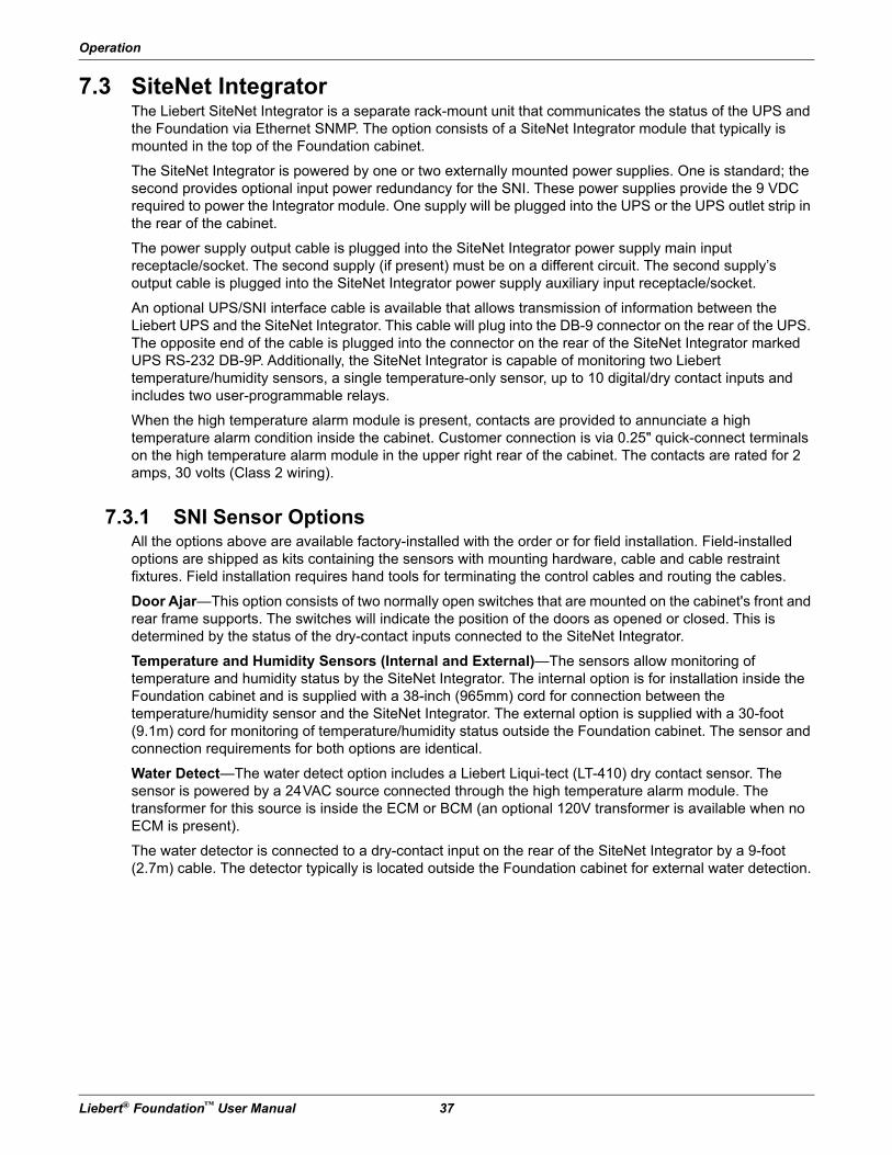
Operation
Liebert® Foundation™ User Manual 37
7.3 SiteNet IntegratorThe Liebert SiteNet Integrator is a separate rack-mount unit that communicates the status of the UPS and the Foundation via Ethernet SNMP. The option consists of a SiteNet Integrator module that typically is mounted in the top of the Foundation cabinet.
The SiteNet Integrator is powered by one or two externally mounted power supplies. One is standard; the second provides optional input power redundancy for the SNI. These power supplies provide the 9 VDC required to power the Integrator module. One supply will be plugged into the UPS or the UPS outlet strip in the rear of the cabinet.
The power supply output cable is plugged into the SiteNet Integrator power supply main input receptacle/socket. The second supply (if present) must be on a different circuit. The second supply’s output cable is plugged into the SiteNet Integrator power supply auxiliary input receptacle/socket.
An optional UPS/SNI interface cable is available that allows transmission of information between the Liebert UPS and the SiteNet Integrator. This cable will plug into the DB-9 connector on the rear of the UPS. The opposite end of the cable is plugged into the connector on the rear of the SiteNet Integrator marked UPS RS-232 DB-9P. Additionally, the SiteNet Integrator is capable of monitoring two Liebert temperature/humidity sensors, a single temperature-only sensor, up to 10 digital/dry contact inputs and includes two user-programmable relays.
When the high temperature alarm module is present, contacts are provided to annunciate a high temperature alarm condition inside the cabinet. Customer connection is via 0.25" quick-connect terminals on the high temperature alarm module in the upper right rear of the cabinet. The contacts are rated for 2 amps, 30 volts (Class 2 wiring).
7.3.1 SNI Sensor OptionsAll the options above are available factory-installed with the order or for field installation. Field-installed options are shipped as kits containing the sensors with mounting hardware, cable and cable restraint fixtures. Field installation requires hand tools for terminating the control cables and routing the cables.
Door Ajar—This option consists of two normally open switches that are mounted on the cabinet's front and rear frame supports. The switches will indicate the position of the doors as opened or closed. This is determined by the status of the dry-contact inputs connected to the SiteNet Integrator.
Temperature and Humidity Sensors (Internal and External)—The sensors allow monitoring of temperature and humidity status by the SiteNet Integrator. The internal option is for installation inside the Foundation cabinet and is supplied with a 38-inch (965mm) cord for connection between the temperature/humidity sensor and the SiteNet Integrator. The external option is supplied with a 30-foot (9.1m) cord for monitoring of temperature/humidity status outside the Foundation cabinet. The sensor and connection requirements for both options are identical.
Water Detect—The water detect option includes a Liebert Liqui-tect (LT-410) dry contact sensor. The sensor is powered by a 24VAC source connected through the high temperature alarm module. The transformer for this source is inside the ECM or BCM (an optional 120V transformer is available when no ECM is present).
The water detector is connected to a dry-contact input on the rear of the SiteNet Integrator by a 9-foot (2.7m) cable. The detector typically is located outside the Foundation cabinet for external water detection.
Operation
38 Liebert® Foundation™ User Manual
Smoke Detector Option—A four-wire smoke detector with normally open contacts, heat sensor and sounder alarm is mounted in the top of the Foundation cabinet. If smoke is detected, the normally open contacts of the smoke detector will close to provide alarm status to the Integrator. The smoke detector sounder alarm will also activate. This alarm is silenced by removing input power to the smoke detector. The smoke detector option requires a 9VDC power source and is normally powered by the High Temperature Alarm Module.
High Temperature Alarm Option - The high temperature alarm is a factory installed sensor / controller module to annunciate high temperatures in the Foundation. When temperatures in the Foundation reach 100°F (38°C), an audible alarm and the BCM (if present) are activated. The high temperature alarm module also includes a dry contact for optional remote monitoring of a high temperature condition. The high temperature alarm is powered by the ECM, if the ECM is not included with the Foundation system, a power supply option is required. The high temperature alarm module also provides input power to the smoke detector option.
Optional Equipment
Liebert® Foundation™ User Manual 39
8.0 Optional Equipment
8.1 Enclosure Systems
8.1.1 Internal Mounting Rails• Front /Rear Rails
• Center-Mount Rails
8.1.2 Door/Panel Options• Plexiglas doors
• perforated doors
• sheet metal doors
• single-door or dual-door
• side panels
• perforated side panels
8.1.3 General Enclosure Options• casters
• external keyboard trays
• sealed entrance cable bundle
• internal light
• cable tray
• EX Cable Management Channels
• cable rings
• Velcro cable management straps
• enclosure cluster kit
• stabilizing plate
• Foundation EX Expansion System
8.1.4 PowerThe Foundation is available with any of the following Liebert UPS models:
On-Line UPS Systems
• GXT2 - 700, 1000, 1500, 2000, 2700 and 3000
• GXT2-6000RT208
Line Interactive Systems
• PS1000, 1440, 2200 and 3000

Optional Equipment
40 Liebert® Foundation™ User Manual
8.1.5 Power StripsLiebert MP Advanced Power Strips—For a list of available units, see MP Advanced Power Strip specifications.
Liebert Managed Power products are available in single- and three-phase power options. The units may be used in 120V, 208-240V or 230V applications, with NEMA or IEC connectors and with or without remote monitoring and individual receptacle control.
For for information about mounting options and details about use, see 9.0 - MP Advanced Power Strips—Installation, 10.0 - Using the Liebert MP Advanced Power Strips, 11.0 - Monitoring and Controlling MP Advanced Power Strips with OpenComms EM PDU and 12.0 - Monitoring and Controlling the Liebert MP Advanced Power Strips with the MP Advanced Access Server.
8.2 EnvironmentalProper temperature levels are maintained by configuring your Foundation with the following options.
8.2.1 ECM Cooling Systems and Options• ECM1000L: for 1000 VA or less UPS load, rack- or top-mount (field-installed), low noise
• ECM2000L: for 2000 VA or less UPS load, rack- or top-mount (field-installed), low noise
• ECM Heat Rejection Fan
• ECM Heat Rejection Duct
• ECM Extension Duct (for multi-enclosure applications)
8.2.2 BCM Cooling Systems and Options• BCM1000: for 1000 VA or less UPS load, rear door mount, low noise
• BCM2000: for 2000 VA or less UPS load, rear door mount, low noise
8.2.3 FAN Cooling Systems & Options• FAN1000: single axial fan, low noise or high ambient
• FAN2000: dual axial fans, low noise or high ambient
• FAN Filter
• XDA: Xtreme Density RackCooler 1000CFM Module
Optional Equipment
Liebert® Foundation™ User Manual 41
8.3 Monitoring Options• MP Advanced Access Server
• OpenComms EM
• SiteNet Integrator
• Load Control Module
• SNI-GXT / PSRS232 Interface Cable
• Internal Temp / Humidity Option - SNI Interface
• External Temp / Humidity Option - SNI Interface
• Door Ajar Sensor Option
• High Temp Alarm
• Water Detected Option
• Power Supply (60Hz Only)
• Smoke Detected Option
8.4 Mounting Options• Fixed shelves, vented, 250lb (113kg) capacity
• Pullout shelves, vented, 130lb (59kg) capacity
• Fixed Rails, 150lb (68kg) capacity
• External Keyboard Tray
• Internal Keyboard Tray (19" [483mm] Rack Keyboard) - HD/K Mounting Frames 19"
• Internal Keyboard Tray (Std Keyboard) - RD/K Mounting Frames 23"
• Mounting Clip nuts and Screws 10-32 or M6 Thread (10 sets)
• Mounting Screws for option (qty 24)
• 23" - 19" (584-483mm) Rack Rail Adapters—1U, 2U, 3U, 4U, 5U and 10U
MP Advanced Power Strips—Installation
42 Liebert® Foundation™ User Manual
9.0 MP Advanced Power Strips—Installation
IMPORTANT SAFETY INSTRUCTIONS—MP ADVANCED POWER STRIPS
9.1 Save These Instructions—MP Advanced Power StripsThis manual contains important safety instructions about your Liebert MP Advanced Power Strips. Read all safety, installation and operating instructions before installing the Liebert MP Advanced Power Strip. Adhere to all warnings on the unit and in this manual. Follow all operating and user instructions. Use only trained and fully-qualified service technicians to install, service and repair this equipment.
The Liebert MP Advanced Power Strip is not intended for use with life support or other designated critical devices. Maximum load must not exceed that shown on the Liebert MP Advanced Power Strip rating label. The Liebert MP Advanced Power Strip is designed for data processing equipment. If uncertain, consult your local dealer or Liebert representative.
Operate the Liebert MP Advanced Power Strip in an indoor environment only in an ambient temperature range of 32°F to +104°F (0°C to +40°C). Install it in a clean environment, free from conductive contaminants, moisture, flammable liquids, gases and corrosive substances.
The Liebert MP Advanced Power Strip contains no user serviceable parts. Under no circumstances attempt to gain internal access due to risk of electric shock or burn. Do not continue to use the Liebert MP Advanced Power Strip if the LED panel or monitoring interface indicators are not in accordance with these operating instructions. Refer all faults to your local dealer, Liebert representative or Liebert Global Services.
Never block or insert any object into the Liebert MP Advanced Power Strip.
DO NOT CONNECT equipment that could overload the Liebert MP Advanced Power Strip.
! WARNINGRisk of electric shock. Can cause serious injury or death.
Unplug/Disconnect the MP Advanced power strip before opening or removing the cover and working within. Hazardous-voltage, bare live-connection terminals are contained within.
MP Advanced Power Strips—Installation
Liebert® Foundation™ User Manual 43
9.2 General ConsiderationsRead all instructions in this section before beginning to make high-voltage connections to your Liebert MP Advanced Power Strip.
Refer to MP Advanced Power Strip specifications to determine the electrical ratings and specifications of your Liebert MP Advanced Power Strip. It is imperative that the power supply and connections match the specifications of the power strip being installed.
Power cables must be routed through the Foundation’s cable management features before the equipment is connected to the Liebert MP Advanced Power Strip and started up. See 5.1 - Cable Management for details on routing power and communication wires.
When connecting the rack equipment to the Liebert MP Advanced Power Strip’s receptacles, arrange cables and connections to avoid tangling and crisscrossing the power cables.
For power management purposes, record the receptacle where each piece of equipment is connected. Receptacles on the Liebert MP Advanced Power Strip have a numerical designation. Liebert MP Advanced Power Strips with more than one circuit are named with numbers and letters.
When connecting power to the Liebert MP Advanced Power Strip’s receptacles, follow generally accepted procedures, such as routing the power cables separately from low-voltage communication and control wires to prevent electromagnetic interference.
9.3 Vertical or Horizontal-MountingMP Advanced Power Strips are available in 19" rack-mount and vertical-mount form to accommodate different installation requirements. See Mounting Method & Size in Table 15-6 for specific configurations.
NOTEConnecting your Liebert MP Advanced Power Strip and rack equipment to a power supply with an incorrect rating in either voltage, amperes or phase may damage the connected equipment and your Liebert MP Advanced Power Strip.
If you have questions about the power supply connections, contact your local Liebert representative or Liebert Global Services at 1-800-LIEBERT.
NOTEShut down and unplug all equipment in your rack enclosure before beginning to connect the equipment to your Liebert MP Advanced Power Strip.
NOTEAll configuration steps in 10.2 - Monitoring Connections—Low Voltage Wiring must be completed before attempting to start up equipment connected to the Liebert MP Advanced Power Strip.
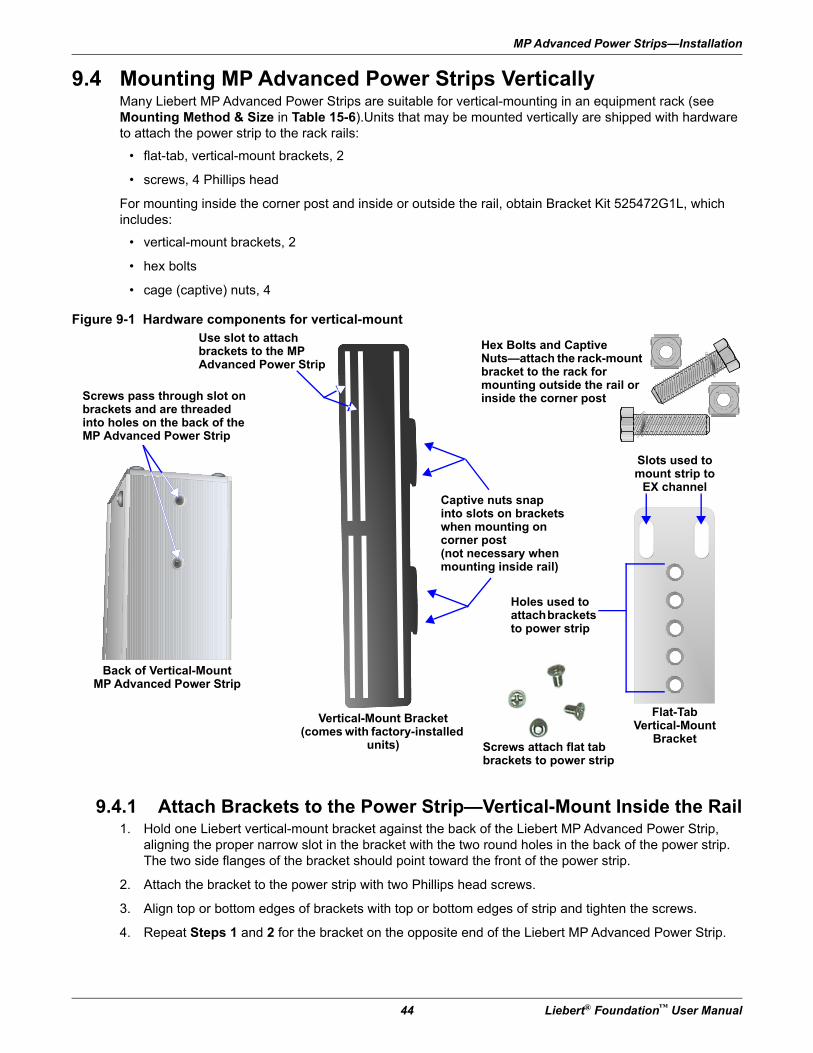
MP Advanced Power Strips—Installation
44 Liebert® Foundation™ User Manual
9.4 Mounting MP Advanced Power Strips VerticallyMany Liebert MP Advanced Power Strips are suitable for vertical-mounting in an equipment rack (see Mounting Method & Size in Table 15-6).Units that may be mounted vertically are shipped with hardware to attach the power strip to the rack rails:
• flat-tab, vertical-mount brackets, 2
• screws, 4 Phillips head
For mounting inside the corner post and inside or outside the rail, obtain Bracket Kit 525472G1L, which includes:
• vertical-mount brackets, 2
• hex bolts
• cage (captive) nuts, 4
Figure 9-1 Hardware components for vertical-mount
9.4.1 Attach Brackets to the Power Strip—Vertical-Mount Inside the Rail1. Hold one Liebert vertical-mount bracket against the back of the Liebert MP Advanced Power Strip,
aligning the proper narrow slot in the bracket with the two round holes in the back of the power strip. The two side flanges of the bracket should point toward the front of the power strip.
2. Attach the bracket to the power strip with two Phillips head screws.
3. Align top or bottom edges of brackets with top or bottom edges of strip and tighten the screws.
4. Repeat Steps 1 and 2 for the bracket on the opposite end of the Liebert MP Advanced Power Strip.
Use slot to attachbrackets to the MP Advanced Power Strip
Hex Bolts and Captive Nuts—attach the rack-mount bracket to the rack for mounting outside the rail or inside the corner post
Captive nuts snapinto slots on brackets when mounting oncorner post(not necessary when mounting inside rail)
Screws pass through slot on brackets and are threaded into holes on the back of the MP Advanced Power Strip
Back of Vertical-MountMP Advanced Power Strip
Flat-TabVertical-Mount
Bracket
Vertical-Mount Bracket(comes with factory-installed
units)
Slots used to mount strip to
EX channel
Screws attach flat tab brackets to power strip
Holes used to attach brackets to power strip
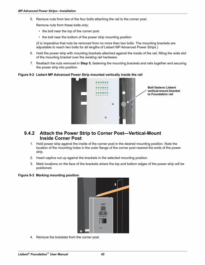
MP Advanced Power Strips—Installation
Liebert® Foundation™ User Manual 45
5. Remove nuts from two of the four bolts attaching the rail to the corner post.
Remove nuts from these bolts only:
• the bolt near the top of the corner post
• the bolt near the bottom of the power strip mounting position
(It is imperative that nuts be removed from no more than two bolts. The mounting brackets are adjustable to reach two bolts for all lengths of Liebert MP Advanced Power Strips.)
6. Hold the power strip with mounting brackets attached against the inside of the rail, fitting the wide slot of the mounting bracket over the existing rail hardware.
7. Reattach the nuts removed in Step 5, fastening the mounting brackets and rails together and securing the power strip into position.
Figure 9-2 Liebert MP Advanced Power Strip mounted vertically inside the rail
9.4.2 Attach the Power Strip to Corner Post—Vertical-Mount Inside Corner Post
1. Hold power strip against the inside of the corner post in the desired mounting position. Note the location of the mounting holes in the outer flange of the corner post nearest the ends of the power strip.
2. Insert captive nut up against the brackets in the selected mounting position.
3. Mark locations on the face of the brackets where the top and bottom edges of the power strip will be positioned.
Figure 9-3 Marking mounting position
4. Remove the brackets from the corner post.
1 2 3 4 5 6
7 8 9 10 11 12
13 14 15 16 17 18
Bolt fastens Liebertvertical-mount bracketto Foundation rail
B
B
C
RS-232
SENSOR INPUTS
A
PWR ALM
SEL
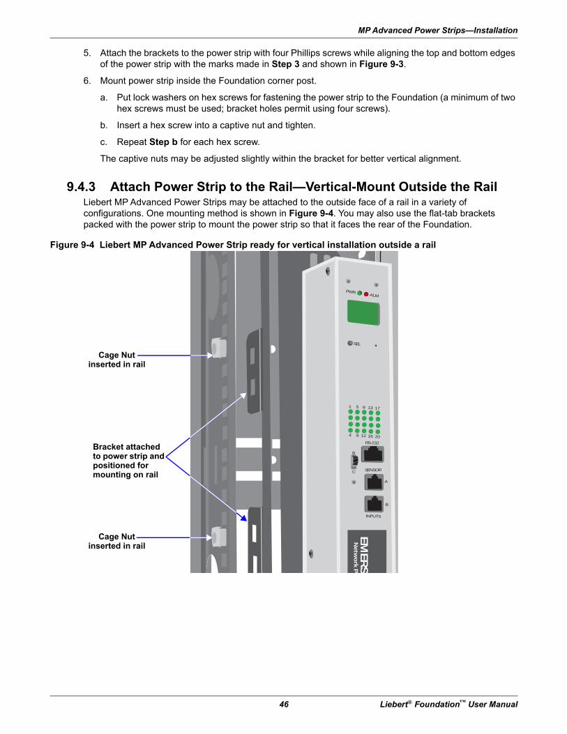
MP Advanced Power Strips—Installation
46 Liebert® Foundation™ User Manual
5. Attach the brackets to the power strip with four Phillips screws while aligning the top and bottom edges of the power strip with the marks made in Step 3 and shown in Figure 9-3.
6. Mount power strip inside the Foundation corner post.
a. Put lock washers on hex screws for fastening the power strip to the Foundation (a minimum of two hex screws must be used; bracket holes permit using four screws).
b. Insert a hex screw into a captive nut and tighten.
c. Repeat Step b for each hex screw.
The captive nuts may be adjusted slightly within the bracket for better vertical alignment.
9.4.3 Attach Power Strip to the Rail—Vertical-Mount Outside the RailLiebert MP Advanced Power Strips may be attached to the outside face of a rail in a variety of configurations. One mounting method is shown in Figure 9-4. You may also use the flat-tab brackets packed with the power strip to mount the power strip so that it faces the rear of the Foundation.
Figure 9-4 Liebert MP Advanced Power Strip ready for vertical installation outside a rail
PWRALM
SEL
1
B
C
A
B
SENSOR
INPUTS
5 9 13 17
4 8 12 16 20
RS-232
EM
ER
SO
Ne
two
rk P
o
Cage Nut inserted in rail
Cage Nut inserted in rail
Bracket attached to power strip and positioned for mounting on rail
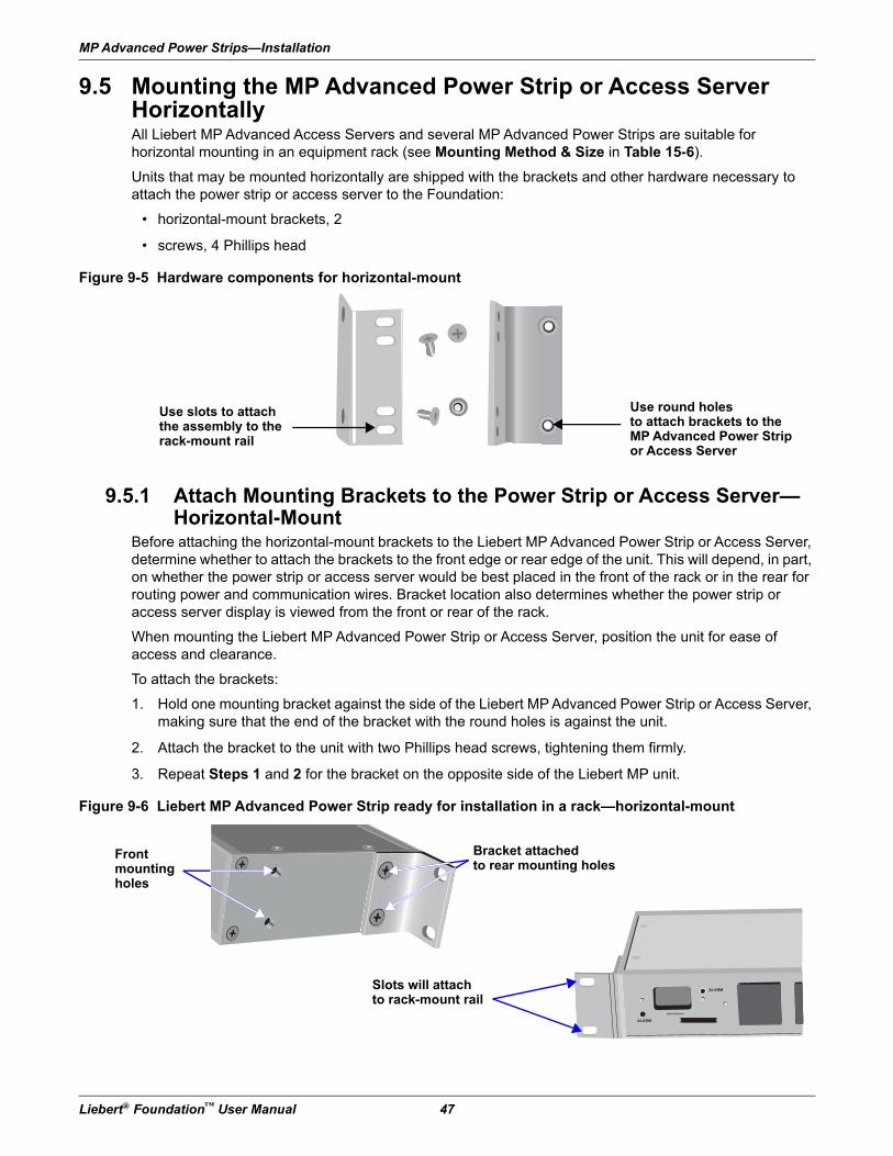
MP Advanced Power Strips—Installation
Liebert® Foundation™ User Manual 47
9.5 Mounting the MP Advanced Power Strip or Access Server HorizontallyAll Liebert MP Advanced Access Servers and several MP Advanced Power Strips are suitable for horizontal mounting in an equipment rack (see Mounting Method & Size in Table 15-6).
Units that may be mounted horizontally are shipped with the brackets and other hardware necessary to attach the power strip or access server to the Foundation:
• horizontal-mount brackets, 2
• screws, 4 Phillips head
Figure 9-5 Hardware components for horizontal-mount
9.5.1 Attach Mounting Brackets to the Power Strip or Access Server—Horizontal-Mount
Before attaching the horizontal-mount brackets to the Liebert MP Advanced Power Strip or Access Server, determine whether to attach the brackets to the front edge or rear edge of the unit. This will depend, in part, on whether the power strip or access server would be best placed in the front of the rack or in the rear for routing power and communication wires. Bracket location also determines whether the power strip or access server display is viewed from the front or rear of the rack.
When mounting the Liebert MP Advanced Power Strip or Access Server, position the unit for ease of access and clearance.
To attach the brackets:
1. Hold one mounting bracket against the side of the Liebert MP Advanced Power Strip or Access Server, making sure that the end of the bracket with the round holes is against the unit.
2. Attach the bracket to the unit with two Phillips head screws, tightening them firmly.
3. Repeat Steps 1 and 2 for the bracket on the opposite side of the Liebert MP unit.
Figure 9-6 Liebert MP Advanced Power Strip ready for installation in a rack—horizontal-mount
Use slots to attachthe assembly to the rack-mount rail
Use round holesto attach brackets to the MP Advanced Power Strip or Access Server
Frontmountingholes
ALARM
ALARM XXXXXXXXXXXXXX
XXXXXXXXXXXXXX
Bracket attachedto rear mounting holes
Slots will attachto rack-mount rail
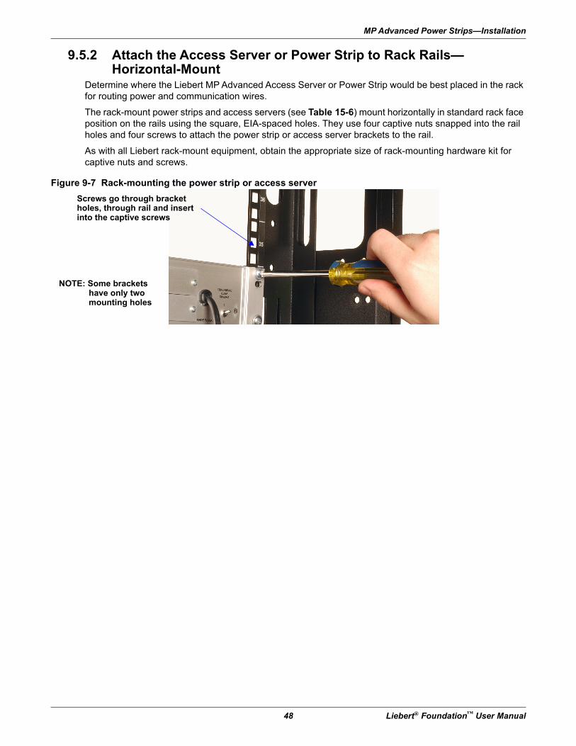
MP Advanced Power Strips—Installation
48 Liebert® Foundation™ User Manual
9.5.2 Attach the Access Server or Power Strip to Rack Rails—Horizontal-Mount
Determine where the Liebert MP Advanced Access Server or Power Strip would be best placed in the rack for routing power and communication wires.
The rack-mount power strips and access servers (see Table 15-6) mount horizontally in standard rack face position on the rails using the square, EIA-spaced holes. They use four captive nuts snapped into the rail holes and four screws to attach the power strip or access server brackets to the rail.
As with all Liebert rack-mount equipment, obtain the appropriate size of rack-mounting hardware kit for captive nuts and screws.
Figure 9-7 Rack-mounting the power strip or access server
Screws go through bracket holes, through rail and insert into the captive screws
NOTE: Some brackets have only two mounting holes
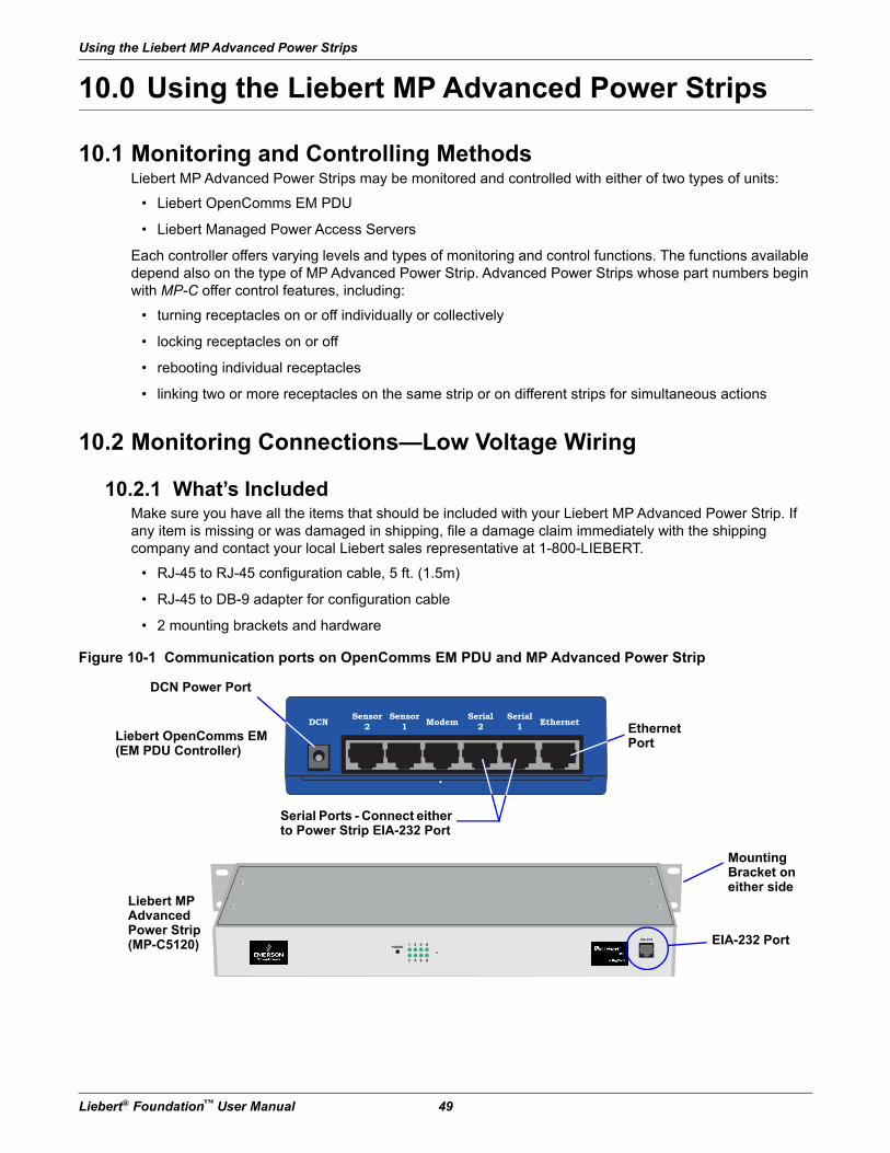
Using the Liebert MP Advanced Power Strips
Liebert® Foundation™ User Manual 49
10.0 Using the Liebert MP Advanced Power Strips
10.1 Monitoring and Controlling MethodsLiebert MP Advanced Power Strips may be monitored and controlled with either of two types of units:
• Liebert OpenComms EM PDU
• Liebert Managed Power Access Servers
Each controller offers varying levels and types of monitoring and control functions. The functions available depend also on the type of MP Advanced Power Strip. Advanced Power Strips whose part numbers begin with MP-C offer control features, including:
• turning receptacles on or off individually or collectively
• locking receptacles on or off
• rebooting individual receptacles
• linking two or more receptacles on the same strip or on different strips for simultaneous actions
10.2 Monitoring Connections—Low Voltage Wiring
10.2.1 What’s IncludedMake sure you have all the items that should be included with your Liebert MP Advanced Power Strip. If any item is missing or was damaged in shipping, file a damage claim immediately with the shipping company and contact your local Liebert sales representative at 1-800-LIEBERT.
• RJ-45 to RJ-45 configuration cable, 5 ft. (1.5m)
• RJ-45 to DB-9 adapter for configuration cable
• 2 mounting brackets and hardware
Figure 10-1 Communication ports on OpenComms EM PDU and MP Advanced Power Strip
POWER1
2
3
4
5
6
8
8
EIA-232
Sensor2
Sensor1
Serial2
Serial1ModemDCN Ethernet
Liebert MP Advanced Power Strip(MP-C5120) EIA-232 Port
EthernetPort
Serial Ports - Connect either to Power Strip EIA-232 Port
Liebert OpenComms EM(EM PDU Controller)
DCN Power Port
Mounting Bracket on either side
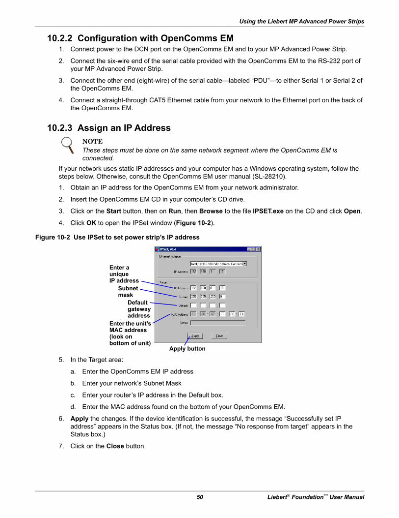
Using the Liebert MP Advanced Power Strips
50 Liebert® Foundation™ User Manual
10.2.2 Configuration with OpenComms EM1. Connect power to the DCN port on the OpenComms EM and to your MP Advanced Power Strip.
2. Connect the six-wire end of the serial cable provided with the OpenComms EM to the RS-232 port of your MP Advanced Power Strip.
3. Connect the other end (eight-wire) of the serial cable—labeled “PDU”—to either Serial 1 or Serial 2 of the OpenComms EM.
4. Connect a straight-through CAT5 Ethernet cable from your network to the Ethernet port on the back of the OpenComms EM.
10.2.3 Assign an IP Address
If your network uses static IP addresses and your computer has a Windows operating system, follow the steps below. Otherwise, consult the OpenComms EM user manual (SL-28210).
1. Obtain an IP address for the OpenComms EM from your network administrator.
2. Insert the OpenComms EM CD in your computer’s CD drive.
3. Click on the Start button, then on Run, then Browse to the file IPSET.exe on the CD and click Open.
4. Click OK to open the IPSet window (Figure 10-2).
Figure 10-2 Use IPSet to set power strip’s IP address
5. In the Target area:
a. Enter the OpenComms EM IP address
b. Enter your network’s Subnet Mask
c. Enter your router’s IP address in the Default box.
d. Enter the MAC address found on the bottom of your OpenComms EM.
6. Apply the changes. If the device identification is successful, the message “Successfully set IP address” appears in the Status box. (If not, the message “No response from target” appears in the Status box.)
7. Click on the Close button.
NOTEThese steps must be done on the same network segment where the OpenComms EM is connected.
Enter a uniqueIP address
Enter the unit’s MAC address (look on bottom of unit)
Apply button
Subnet mask
Default gatewayaddress
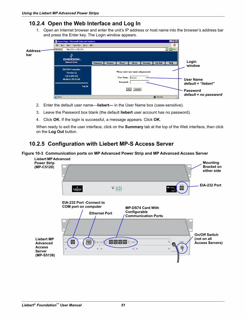
Using the Liebert MP Advanced Power Strips
Liebert® Foundation™ User Manual 51
10.2.4 Open the Web Interface and Log In1. Open an Internet browser and enter the unit’s IP address or host name into the browser’s address bar
and press the Enter key. The Login window appears.
2. Enter the default user name—liebert— in the User Name box (case-sensitive).
3. Leave the Password box blank (the default liebert user account has no password).
4. Click OK. If the login is successful, a message appears. Click OK.
When ready to exit the user interface, click on the Summary tab at the top of the Web interface, then click on the Log Out button.
10.2.5 Configuration with Liebert MP-S Access Server
Figure 10-3 Communication ports on MP Advanced Power Strip and MP Advanced Access Server
Login window
Address bar
User Name default = “liebert”
Password default = no password
1234
CX
3C
X4
EIA-232
EIA-232
I/0 MO
DU
LE
NETW
ORK
INTERFA
CE
ETHERN
ET
ROUTE LINE
DS74
MADE IN USA
100-240VAC??????????
0.21-0.12AMPS
DS62
CX
1 C
X2
POWER1
2
3
4
5
6
8
8
EIA-232
EIA-232 Port -Connect to COM port on computer
Ethernet Port
MP-DS74 Card WithConfigurableCommunication Ports
Liebert MP Advanced Power Strip(MP-C5120)
Liebert MP Advanced Access Server (MP-S5138)
EIA-232 Port
Mounting Bracket on either side
On/Off Switch (not on all Access Servers)
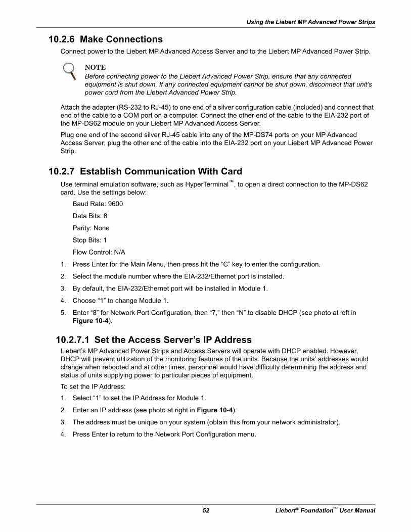
Using the Liebert MP Advanced Power Strips
52 Liebert® Foundation™ User Manual
10.2.6 Make ConnectionsConnect power to the Liebert MP Advanced Access Server and to the Liebert MP Advanced Power Strip.
Attach the adapter (RS-232 to RJ-45) to one end of a silver configuration cable (included) and connect that end of the cable to a COM port on a computer. Connect the other end of the cable to the EIA-232 port of the MP-DS62 module on your Liebert MP Advanced Access Server.
Plug one end of the second silver RJ-45 cable into any of the MP-DS74 ports on your MP Advanced Access Server; plug the other end of the cable into the EIA-232 port on your Liebert MP Advanced Power Strip.
10.2.7 Establish Communication With CardUse terminal emulation software, such as HyperTerminal™, to open a direct connection to the MP-DS62 card. Use the settings below:
Baud Rate: 9600
Data Bits: 8
Parity: None
Stop Bits: 1
Flow Control: N/A
1. Press Enter for the Main Menu, then press hit the “C” key to enter the configuration.
2. Select the module number where the EIA-232/Ethernet port is installed.
3. By default, the EIA-232/Ethernet port will be installed in Module 1.
4. Choose “1” to change Module 1.
5. Enter “8” for Network Port Configuration, then “7,” then “N” to disable DHCP (see photo at left in Figure 10-4).
10.2.7.1 Set the Access Server’s IP AddressLiebert’s MP Advanced Power Strips and Access Servers will operate with DHCP enabled. However, DHCP will prevent utilization of the monitoring features of the units. Because the units’ addresses would change when rebooted and at other times, personnel would have difficulty determining the address and status of units supplying power to particular pieces of equipment.
To set the IP Address:
1. Select “1” to set the IP Address for Module 1.
2. Enter an IP address (see photo at right in Figure 10-4).
3. The address must be unique on your system (obtain this from your network administrator).
4. Press Enter to return to the Network Port Configuration menu.
NOTEBefore connecting power to the Liebert Advanced Power Strip, ensure that any connected equipment is shut down. If any connected equipment cannot be shut down, disconnect that unit’s power cord from the Liebert Advanced Power Strip.
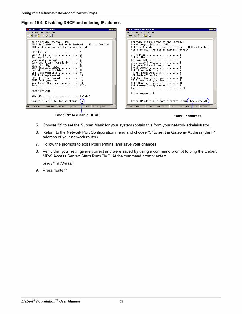
Using the Liebert MP Advanced Power Strips
Liebert® Foundation™ User Manual 53
Figure 10-4 Disabling DHCP and entering IP address
5. Choose “2” to set the Subnet Mask for your system (obtain this from your network administrator).
6. Return to the Network Port Configuration menu and choose “3” to set the Gateway Address (the IP address of your network router).
7. Follow the prompts to exit HyperTerminal and save your changes.
8. Verify that your settings are correct and were saved by using a command prompt to ping the Liebert MP-S Access Server: Start>Run>CMD. At the command prompt enter:
ping [IP address]
9. Press “Enter.”
Enter IP addressEnter “N” to disable DHCP
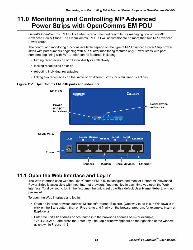
Monitoring and Controlling MP Advanced Power Strips with OpenComms EM PDU
54 Liebert® Foundation™ User Manual
11.0 Monitoring and Controlling MP Advanced Power Strips with OpenComms EM PDU
Liebert’s OpenComms EM PDU is Liebert’s recommended controller for managing one or two MP Advanced Power Strips. The OpenComms EM PDU will accommodate no more than two MP Advanced Power Strips.
The control and monitoring functions available depend on the type of MP Advanced Power Strip. Power strips with part numbers beginning with MP-M offer monitoring features only. Power strips with part numbers beginning with MP-C, offer control features, including:
• turning receptacles on or off individually or collectively
• locking receptacles on or off
• rebooting individual receptacles
• linking two receptacles on the same or on different strips for simultaneous actions
Figure 11-1 OpenComms EM PDU ports and indicators
11.1 Open the Web Interface and Log InThe Web interface used with the OpenComms EM PDU to configure and monitor Liebert MP Advanced Power Strips is accessible with most Internet browsers. You must log in each time you open the Web interface. To allow you to log in the first time, the unit is set up with a default User Name, liebert, with no password.
To open the Web interface and log in:
• Open an Internet browser, such as Microsoft® Internet Explorer. (One way to do this in Windows is to click on the Start button, then on Programs and finally on the browser program, for example, Internet Explorer.)
• Enter the unit’s IP address or host name into the browser’s address bar—for example, 126.4.203.246—and press the Enter key. The Login window appears on the right side of the window, as shown in Figure 11-2.
REAR VIEWSensor2
Sensor1
Serial2
Serial1ModemDCN Ethernet
Power
Sensors Serial devicesModem Ethernet
EMERSONNetwork Power
Power Link Serial
1
ModemSerial
2
Sensor
1
Sensor
2
Power and portindicators
TOP VIEW
Serial device indicators
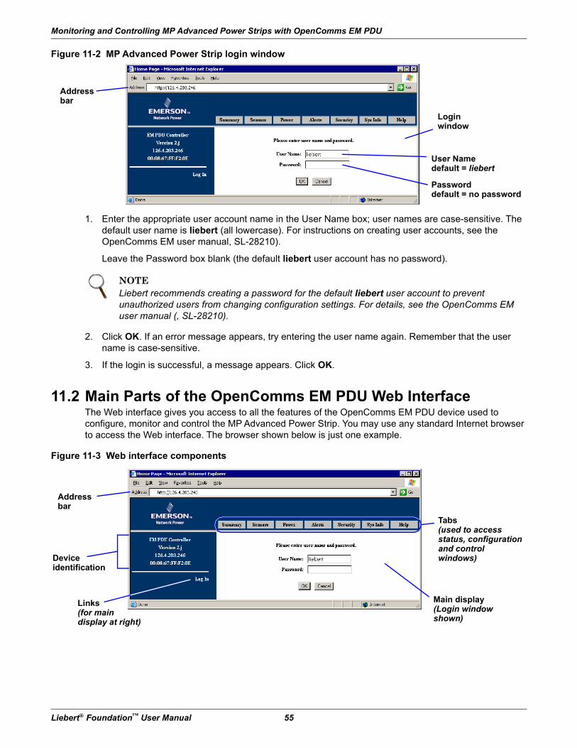
Monitoring and Controlling MP Advanced Power Strips with OpenComms EM PDU
Liebert® Foundation™ User Manual 55
Figure 11-2 MP Advanced Power Strip login window
1. Enter the appropriate user account name in the User Name box; user names are case-sensitive. The default user name is liebert (all lowercase). For instructions on creating user accounts, see the OpenComms EM user manual, SL-28210).
Leave the Password box blank (the default liebert user account has no password).
2. Click OK. If an error message appears, try entering the user name again. Remember that the user name is case-sensitive.
3. If the login is successful, a message appears. Click OK.
11.2 Main Parts of the OpenComms EM PDU Web InterfaceThe Web interface gives you access to all the features of the OpenComms EM PDU device used to configure, monitor and control the MP Advanced Power Strip. You may use any standard Internet browser to access the Web interface. The browser shown below is just one example.
Figure 11-3 Web interface components
NOTELiebert recommends creating a password for the default liebert user account to prevent unauthorized users from changing configuration settings. For details, see the OpenComms EM user manual (, SL-28210).
Login window
Address bar
User Name default = liebert
Password default = no password
Main display(Login window shown)
Tabs(used to accessstatus, configuration and controlwindows)
Address bar
Deviceidentification
Links (for main display at right)
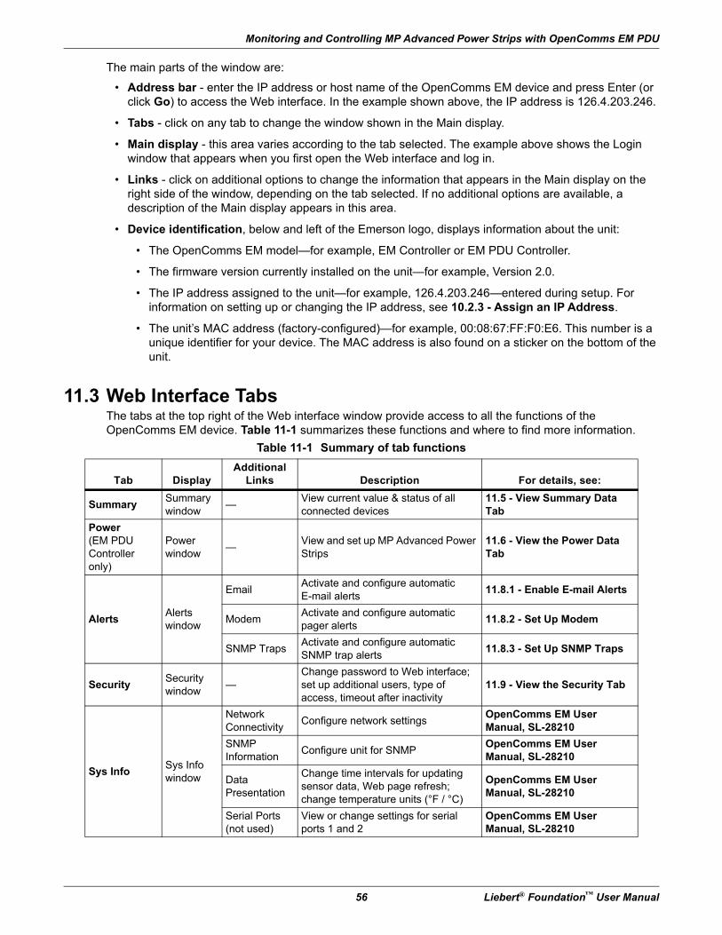
Monitoring and Controlling MP Advanced Power Strips with OpenComms EM PDU
56 Liebert® Foundation™ User Manual
The main parts of the window are:
• Address bar - enter the IP address or host name of the OpenComms EM device and press Enter (or click Go) to access the Web interface. In the example shown above, the IP address is 126.4.203.246.
• Tabs - click on any tab to change the window shown in the Main display.
• Main display - this area varies according to the tab selected. The example above shows the Login window that appears when you first open the Web interface and log in.
• Links - click on additional options to change the information that appears in the Main display on the right side of the window, depending on the tab selected. If no additional options are available, a description of the Main display appears in this area.
• Device identification, below and left of the Emerson logo, displays information about the unit:
• The OpenComms EM model—for example, EM Controller or EM PDU Controller.
• The firmware version currently installed on the unit—for example, Version 2.0.
• The IP address assigned to the unit—for example, 126.4.203.246—entered during setup. For information on setting up or changing the IP address, see 10.2.3 - Assign an IP Address.
• The unit’s MAC address (factory-configured)—for example, 00:08:67:FF:F0:E6. This number is a unique identifier for your device. The MAC address is also found on a sticker on the bottom of the unit.
11.3 Web Interface TabsThe tabs at the top right of the Web interface window provide access to all the functions of the OpenComms EM device. Table 11-1 summarizes these functions and where to find more information.
Table 11-1 Summary of tab functions
Tab DisplayAdditional
Links Description For details, see:
SummarySummarywindow
—View current value & status of all connected devices
11.5 - View Summary Data Tab
Power(EM PDU Controlleronly)
Powerwindow
—View and set up MP Advanced Power Strips
11.6 - View the Power Data Tab
AlertsAlertswindow
EmailActivate and configure automatic E-mail alerts
11.8.1 - Enable E-mail Alerts
ModemActivate and configure automatic pager alerts
11.8.2 - Set Up Modem
SNMP TrapsActivate and configure automatic SNMP trap alerts
11.8.3 - Set Up SNMP Traps
SecuritySecuritywindow
—Change password to Web interface; set up additional users, type of access, timeout after inactivity
11.9 - View the Security Tab
Sys InfoSys Infowindow
NetworkConnectivity
Configure network settingsOpenComms EM User Manual, SL-28210
SNMPInformation
Configure unit for SNMPOpenComms EM User Manual, SL-28210
DataPresentation
Change time intervals for updating sensor data, Web page refresh; change temperature units (°F / °C)
OpenComms EM User Manual, SL-28210
Serial Ports(not used)
View or change settings for serial ports 1 and 2
OpenComms EM User Manual, SL-28210
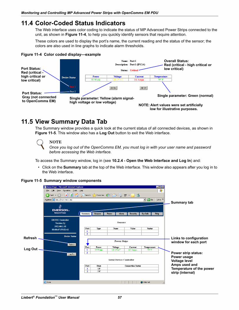
Monitoring and Controlling MP Advanced Power Strips with OpenComms EM PDU
Liebert® Foundation™ User Manual 57
11.4 Color-Coded Status IndicatorsThe Web interface uses color coding to indicate the status of MP Advanced Power Strips connected to the unit, as shown in Figure 11-4, to help you quickly identify sensors that require attention.
These colors are used to display the port’s name, the current reading and the status of the sensor; the colors are also used in line graphs to indicate alarm thresholds.
Figure 11-4 Color coded display—example
11.5 View Summary Data TabThe Summary window provides a quick look at the current status of all connected devices, as shown in Figure 11-5. This window also has a Log Out button to exit the Web interface.
To access the Summary window, log in (see 10.2.4 - Open the Web Interface and Log In) and:
• Click on the Summary tab at the top of the Web interface. This window also appears after you log in to the Web interface.
Figure 11-5 Summary window components
NOTEOnce you log out of the OpenComms EM, you must log in with your user name and password before accessing the Web interface.
Single parameter: Green (normal)
Overall Status:Red (critical - high critical or low critical)Port Status:
Red (critical - high critical or low critical)
Single parameter: Yellow (alarm signal- high voltage or low voltage)
Port Status:Gray (not connected to OpenComms EM)
NOTE: Alert values were set artificially low for illustrative purposes.
Power strip status:Power usageVoltage levelAmps used andTemperature of the power strip (internal)
Summary tab
Refresh
Log Out
Links to configuration window for each port
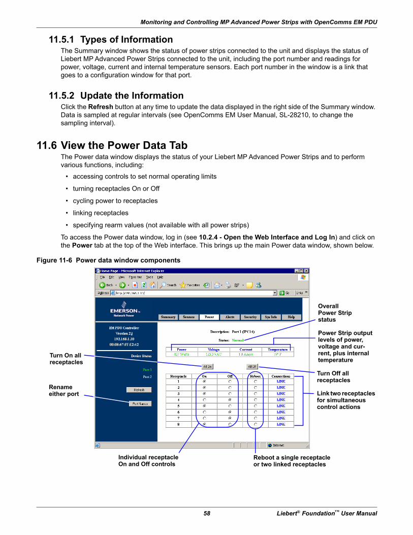
Monitoring and Controlling MP Advanced Power Strips with OpenComms EM PDU
58 Liebert® Foundation™ User Manual
11.5.1 Types of InformationThe Summary window shows the status of power strips connected to the unit and displays the status of Liebert MP Advanced Power Strips connected to the unit, including the port number and readings for power, voltage, current and internal temperature sensors. Each port number in the window is a link that goes to a configuration window for that port.
11.5.2 Update the InformationClick the Refresh button at any time to update the data displayed in the right side of the Summary window. Data is sampled at regular intervals (see OpenComms EM User Manual, SL-28210, to change the sampling interval).
11.6 View the Power Data TabThe Power data window displays the status of your Liebert MP Advanced Power Strips and to perform various functions, including:
• accessing controls to set normal operating limits
• turning receptacles On or Off
• cycling power to receptacles
• linking receptacles
• specifying rearm values (not available with all power strips)
To access the Power data window, log in (see 10.2.4 - Open the Web Interface and Log In) and click on the Power tab at the top of the Web interface. This brings up the main Power data window, shown below.
Figure 11-6 Power data window components
Turn On all receptacles
Overall Power Strip status
Power Strip output levels of power, voltage and cur-rent, plus internal temperature
Individual receptacle On and Off controls
Turn Off all receptacles
Link two receptacles for simultaneous control actions
Reboot a single receptacle or two linked receptacles
Rename either port
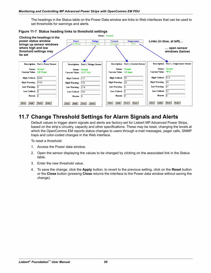
Monitoring and Controlling MP Advanced Power Strips with OpenComms EM PDU
Liebert® Foundation™ User Manual 59
The headings in the Status table on the Power Data window are links to Web interfaces that can be used to set thresholds for warnings and alerts.
Figure 11-7 Status heading links to threshold settings
11.7 Change Threshold Settings for Alarm Signals and AlertsDefault values to trigger alarm signals and alerts are factory-set for Liebert MP Advanced Power Strips, based on the strip’s circuitry, capacity and other specifications. These may be reset, changing the levels at which the OpenComms EM reports status changes to users through e-mail messages, pager calls, SNMP traps and color-coded changes in the Web interface.
To reset a threshold:
1. Access the Power data window.
2. Open the sensor displaying the values to be changed by clicking on the associated link in the Status table.
3. Enter the new threshold value.
4. To save the change, click the Apply button; to revert to the previous setting, click on the Reset button or the Close button (pressing Close returns the interface to the Power data window without saving the change).
Clicking the headings in the power status window brings up sensor windows where high and lowthreshold settings maybe set
Links (in blue, at left)...
. .. open sensor windows (below)
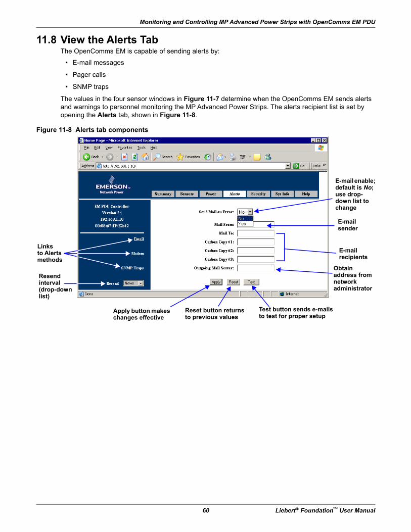
Monitoring and Controlling MP Advanced Power Strips with OpenComms EM PDU
60 Liebert® Foundation™ User Manual
11.8 View the Alerts TabThe OpenComms EM is capable of sending alerts by:
• E-mail messages
• Pager calls
• SNMP traps
The values in the four sensor windows in Figure 11-7 determine when the OpenComms EM sends alerts and warnings to personnel monitoring the MP Advanced Power Strips. The alerts recipient list is set by opening the Alerts tab, shown in Figure 11-8.
Figure 11-8 Alerts tab components
Linksto Alerts methods
Resendinterval(drop-down list)
E-mail enable;default is No; use drop-down list to change
E-mailsender
E-mail recipients
Apply button makes changes effective
Reset button returns to previous values
Test button sends e-mails to test for proper setup
Obtain address from network administrator
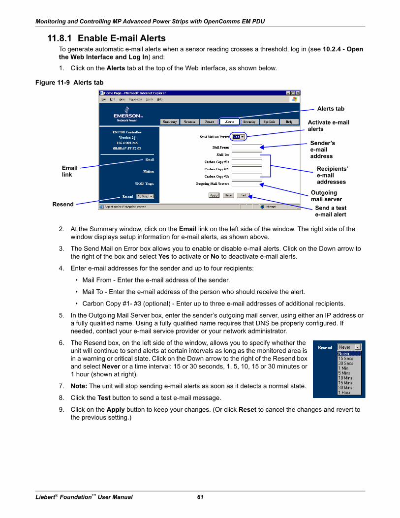
Monitoring and Controlling MP Advanced Power Strips with OpenComms EM PDU
Liebert® Foundation™ User Manual 61
11.8.1 Enable E-mail AlertsTo generate automatic e-mail alerts when a sensor reading crosses a threshold, log in (see 10.2.4 - Open the Web Interface and Log In) and:
1. Click on the Alerts tab at the top of the Web interface, as shown below.
Figure 11-9 Alerts tab
2. At the Summary window, click on the Email link on the left side of the window. The right side of the window displays setup information for e-mail alerts, as shown above.
3. The Send Mail on Error box allows you to enable or disable e-mail alerts. Click on the Down arrow to the right of the box and select Yes to activate or No to deactivate e-mail alerts.
4. Enter e-mail addresses for the sender and up to four recipients:
• Mail From - Enter the e-mail address of the sender.
• Mail To - Enter the e-mail address of the person who should receive the alert.
• Carbon Copy #1- #3 (optional) - Enter up to three e-mail addresses of additional recipients.
5. In the Outgoing Mail Server box, enter the sender’s outgoing mail server, using either an IP address or a fully qualified name. Using a fully qualified name requires that DNS be properly configured. If needed, contact your e-mail service provider or your network administrator.
6. The Resend box, on the left side of the window, allows you to specify whether the unit will continue to send alerts at certain intervals as long as the monitored area is in a warning or critical state. Click on the Down arrow to the right of the Resend box and select Never or a time interval: 15 or 30 seconds, 1, 5, 10, 15 or 30 minutes or 1 hour (shown at right).
7. Note: The unit will stop sending e-mail alerts as soon as it detects a normal state.
8. Click the Test button to send a test e-mail message.
9. Click on the Apply button to keep your changes. (Or click Reset to cancel the changes and revert to the previous setting.)
Alerts tab
Email link
Activate e-mail alerts
Recipients’ e-mail addresses
Sender’se-mail address
Outgoingmail server
ResendSend a test e-mail alert
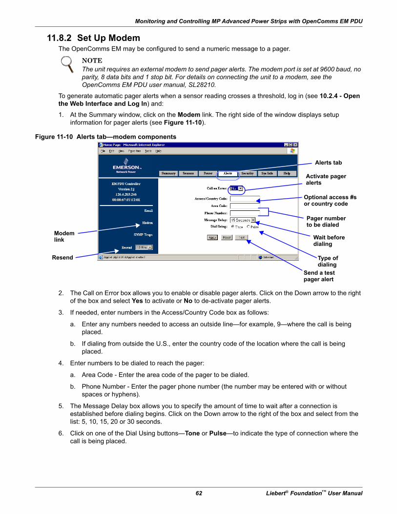
Monitoring and Controlling MP Advanced Power Strips with OpenComms EM PDU
62 Liebert® Foundation™ User Manual
11.8.2 Set Up ModemThe OpenComms EM may be configured to send a numeric message to a pager.
To generate automatic pager alerts when a sensor reading crosses a threshold, log in (see 10.2.4 - Open the Web Interface and Log In) and:
1. At the Summary window, click on the Modem link. The right side of the window displays setup information for pager alerts (see Figure 11-10).
Figure 11-10 Alerts tab—modem components
2. The Call on Error box allows you to enable or disable pager alerts. Click on the Down arrow to the right of the box and select Yes to activate or No to de-activate pager alerts.
3. If needed, enter numbers in the Access/Country Code box as follows:
a. Enter any numbers needed to access an outside line—for example, 9—where the call is being placed.
b. If dialing from outside the U.S., enter the country code of the location where the call is being placed.
4. Enter numbers to be dialed to reach the pager:
a. Area Code - Enter the area code of the pager to be dialed.
b. Phone Number - Enter the pager phone number (the number may be entered with or without spaces or hyphens).
5. The Message Delay box allows you to specify the amount of time to wait after a connection is established before dialing begins. Click on the Down arrow to the right of the box and select from the list: 5, 10, 15, 20 or 30 seconds.
6. Click on one of the Dial Using buttons—Tone or Pulse—to indicate the type of connection where the call is being placed.
NOTEThe unit requires an external modem to send pager alerts. The modem port is set at 9600 baud, no parity, 8 data bits and 1 stop bit. For details on connecting the unit to a modem, see the OpenComms EM PDU user manual, SL28210.
Modem link
Activate pager alerts
Wait before dialing
Pager number to be dialed
Type of dialing
Resend
Optional access #s or country code
Send a test pager alert
Alerts tab
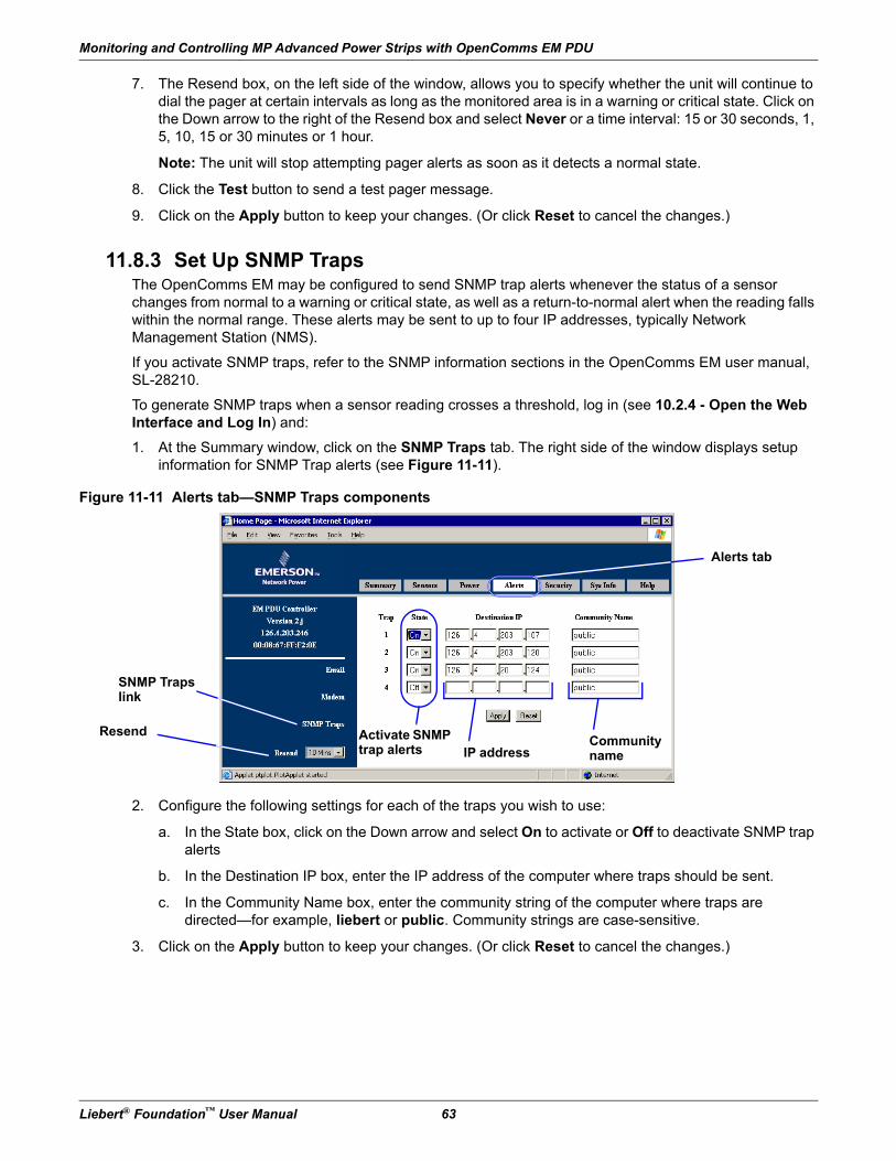
Monitoring and Controlling MP Advanced Power Strips with OpenComms EM PDU
Liebert® Foundation™ User Manual 63
7. The Resend box, on the left side of the window, allows you to specify whether the unit will continue to dial the pager at certain intervals as long as the monitored area is in a warning or critical state. Click on the Down arrow to the right of the Resend box and select Never or a time interval: 15 or 30 seconds, 1, 5, 10, 15 or 30 minutes or 1 hour.
Note: The unit will stop attempting pager alerts as soon as it detects a normal state.
8. Click the Test button to send a test pager message.
9. Click on the Apply button to keep your changes. (Or click Reset to cancel the changes.)
11.8.3 Set Up SNMP TrapsThe OpenComms EM may be configured to send SNMP trap alerts whenever the status of a sensor changes from normal to a warning or critical state, as well as a return-to-normal alert when the reading falls within the normal range. These alerts may be sent to up to four IP addresses, typically Network Management Station (NMS).
If you activate SNMP traps, refer to the SNMP information sections in the OpenComms EM user manual, SL-28210.
To generate SNMP traps when a sensor reading crosses a threshold, log in (see 10.2.4 - Open the Web Interface and Log In) and:
1. At the Summary window, click on the SNMP Traps tab. The right side of the window displays setup information for SNMP Trap alerts (see Figure 11-11).
Figure 11-11 Alerts tab—SNMP Traps components
2. Configure the following settings for each of the traps you wish to use:
a. In the State box, click on the Down arrow and select On to activate or Off to deactivate SNMP trap alerts
b. In the Destination IP box, enter the IP address of the computer where traps should be sent.
c. In the Community Name box, enter the community string of the computer where traps are directed—for example, liebert or public. Community strings are case-sensitive.
3. Click on the Apply button to keep your changes. (Or click Reset to cancel the changes.)
SNMP Trapslink
Activate SNMP trap alerts
Resend
IP addressCommunity name
Alerts tab
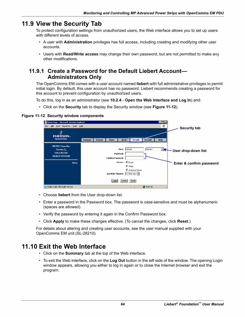
Monitoring and Controlling MP Advanced Power Strips with OpenComms EM PDU
64 Liebert® Foundation™ User Manual
11.9 View the Security TabTo protect configuration settings from unauthorized users, the Web interface allows you to set up users with different levels of access.
• A user with Administration privileges has full access, including creating and modifying other user accounts.
• Users with Read/Write access may change their own password, but are not permitted to make any other modifications.
11.9.1 Create a Password for the Default Liebert Account—Administrators Only
The OpenComms EM comes with a user account named liebert with full administrative privileges to permit initial login. By default, this user account has no password. Liebert recommends creating a password for this account to prevent configuration by unauthorized users.
To do this, log in as an administrator (see 10.2.4 - Open the Web Interface and Log In) and:
• Click on the Security tab to display the Security window (see Figure 11-12).
Figure 11-12 Security window components
• Choose liebert from the User drop-down list.
• Enter a password in the Password box. The password is case-sensitive and must be alphanumeric (spaces are allowed).
• Verify the password by entering it again in the Confirm Password box.
• Click Apply to make these changes effective. (To cancel the changes, click Reset.)
For details about altering and creating user accounts, see the user manual supplied with your OpenComms EM unit (SL-28210).
11.10 Exit the Web Interface• Click on the Summary tab at the top of the Web interface.
• To exit the Web interface, click on the Log Out button in the left side of the window. The opening Login window appears, allowing you either to log in again or to close the Internet browser and exit the program.
Enter & confirm password
User drop-down list
Security tab
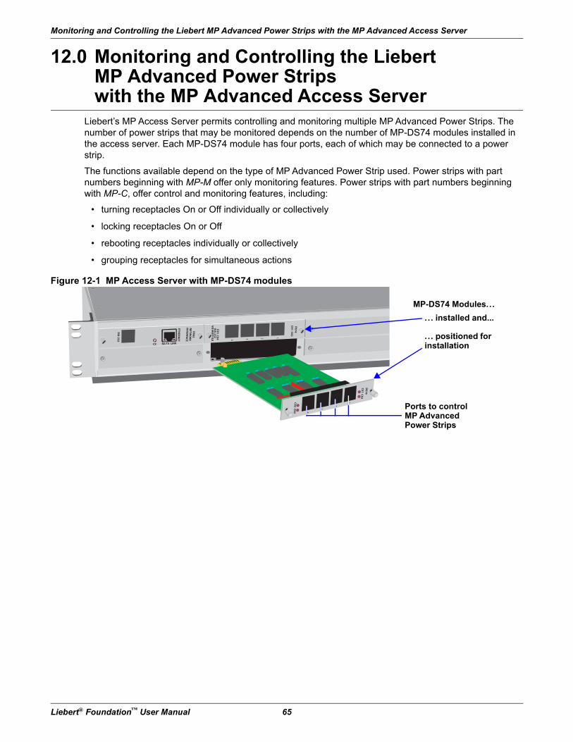
Monitoring and Controlling the Liebert MP Advanced Power Strips with the MP Advanced Access Server
Liebert® Foundation™ User Manual 65
12.0 Monitoring and Controlling the Liebert MP Advanced Power Strips with the MP Advanced Access Server
Liebert’s MP Access Server permits controlling and monitoring multiple MP Advanced Power Strips. The number of power strips that may be monitored depends on the number of MP-DS74 modules installed in the access server. Each MP-DS74 module has four ports, each of which may be connected to a power strip.
The functions available depend on the type of MP Advanced Power Strip used. Power strips with part numbers beginning with MP-M offer only monitoring features. Power strips with part numbers beginning with MP-C, offer control and monitoring features, including:
• turning receptacles On or Off individually or collectively
• locking receptacles On or Off
• rebooting receptacles individually or collectively
• grouping receptacles for simultaneous actions
Figure 12-1 MP Access Server with MP-DS74 modules
1
DS7
4C
X1
CX
2
CX
3 C
X4
2
3
4
1
DS7
4DS6
2N
ETW
OR
KIN
TERFA
CE
ETHER
NET
EIA-2
32
CX
1 C
X2
CX
3 C
X4
CX RX/TX LINK
EIA-2
32
VO
MO
DU
LE 234
MP-DS74 Modules...
.. . installed and...
.. . positioned for installation
Ports to control MP Advanced Power Strips
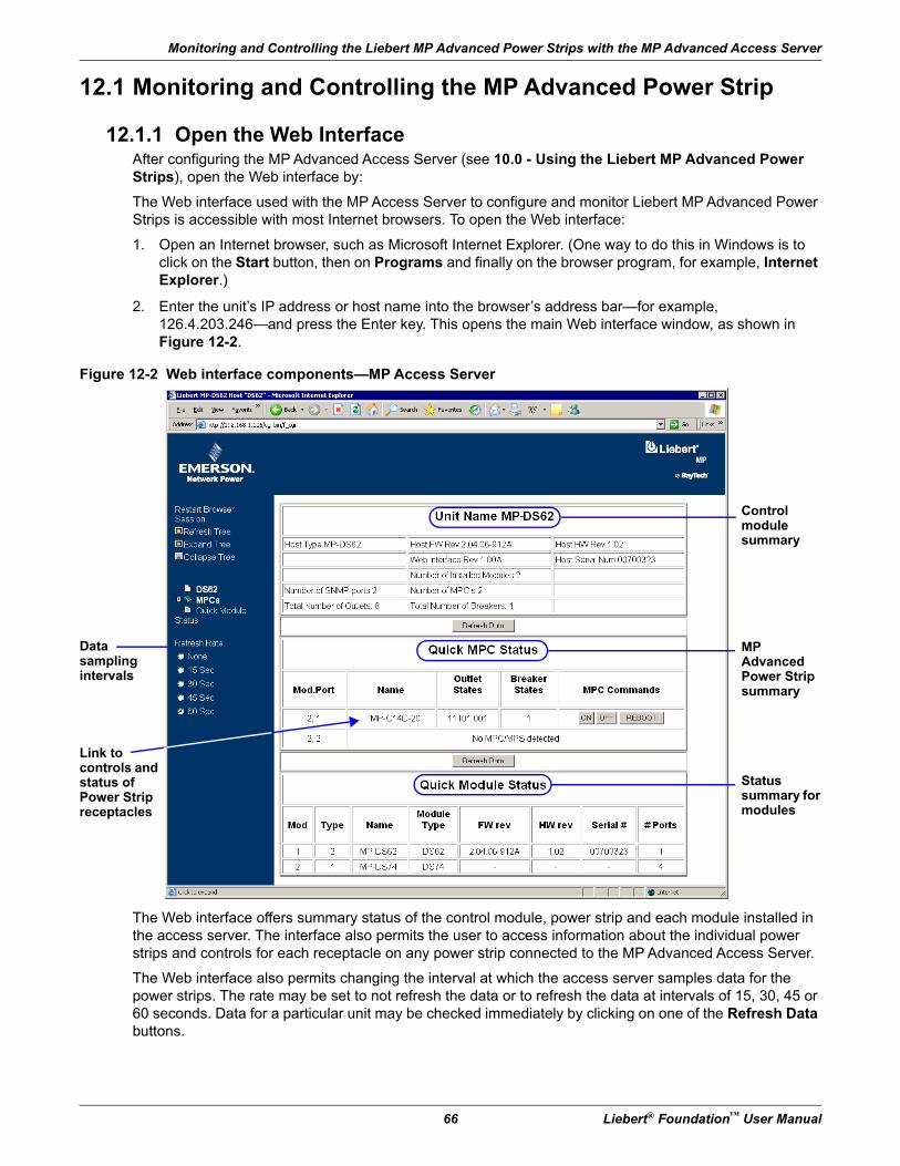
Monitoring and Controlling the Liebert MP Advanced Power Strips with the MP Advanced Access Server
66 Liebert® Foundation™ User Manual
12.1 Monitoring and Controlling the MP Advanced Power Strip
12.1.1 Open the Web InterfaceAfter configuring the MP Advanced Access Server (see 10.0 - Using the Liebert MP Advanced Power Strips), open the Web interface by:
The Web interface used with the MP Access Server to configure and monitor Liebert MP Advanced Power Strips is accessible with most Internet browsers. To open the Web interface:
1. Open an Internet browser, such as Microsoft Internet Explorer. (One way to do this in Windows is to click on the Start button, then on Programs and finally on the browser program, for example, Internet Explorer.)
2. Enter the unit’s IP address or host name into the browser’s address bar—for example, 126.4.203.246—and press the Enter key. This opens the main Web interface window, as shown in Figure 12-2.
Figure 12-2 Web interface components—MP Access Server
The Web interface offers summary status of the control module, power strip and each module installed in the access server. The interface also permits the user to access information about the individual power strips and controls for each receptacle on any power strip connected to the MP Advanced Access Server.
The Web interface also permits changing the interval at which the access server samples data for the power strips. The rate may be set to not refresh the data or to refresh the data at intervals of 15, 30, 45 or 60 seconds. Data for a particular unit may be checked immediately by clicking on one of the Refresh Data buttons.
Control module summary
MP Advanced Power Strip summary
Statussummary for modules
Link tocontrols and status of Power Strip receptacles
Datasamplingintervals
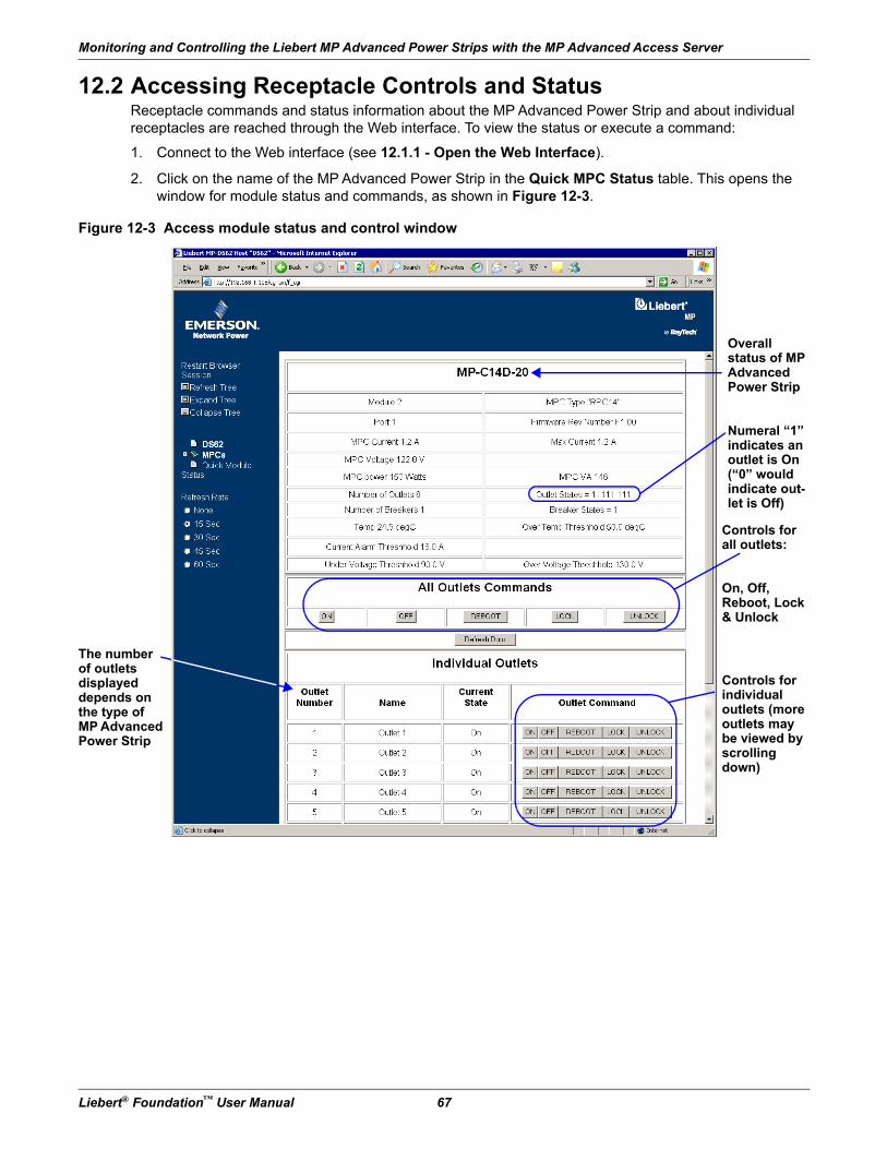
Monitoring and Controlling the Liebert MP Advanced Power Strips with the MP Advanced Access Server
Liebert® Foundation™ User Manual 67
12.2 Accessing Receptacle Controls and StatusReceptacle commands and status information about the MP Advanced Power Strip and about individual receptacles are reached through the Web interface. To view the status or execute a command:
1. Connect to the Web interface (see 12.1.1 - Open the Web Interface).
2. Click on the name of the MP Advanced Power Strip in the Quick MPC Status table. This opens the window for module status and commands, as shown in Figure 12-3.
Figure 12-3 Access module status and control window
The number of outletsdisplayed depends on the type of MP Advanced Power Strip
Controls for all outlets:
On, Off, Reboot, Lock & Unlock
Controls for individual outlets (more outlets may be viewed by scrolling down)
Overallstatus of MP Advanced Power Strip
Numeral “1” indicates an outlet is On (“0” would indicate out-let is Off)
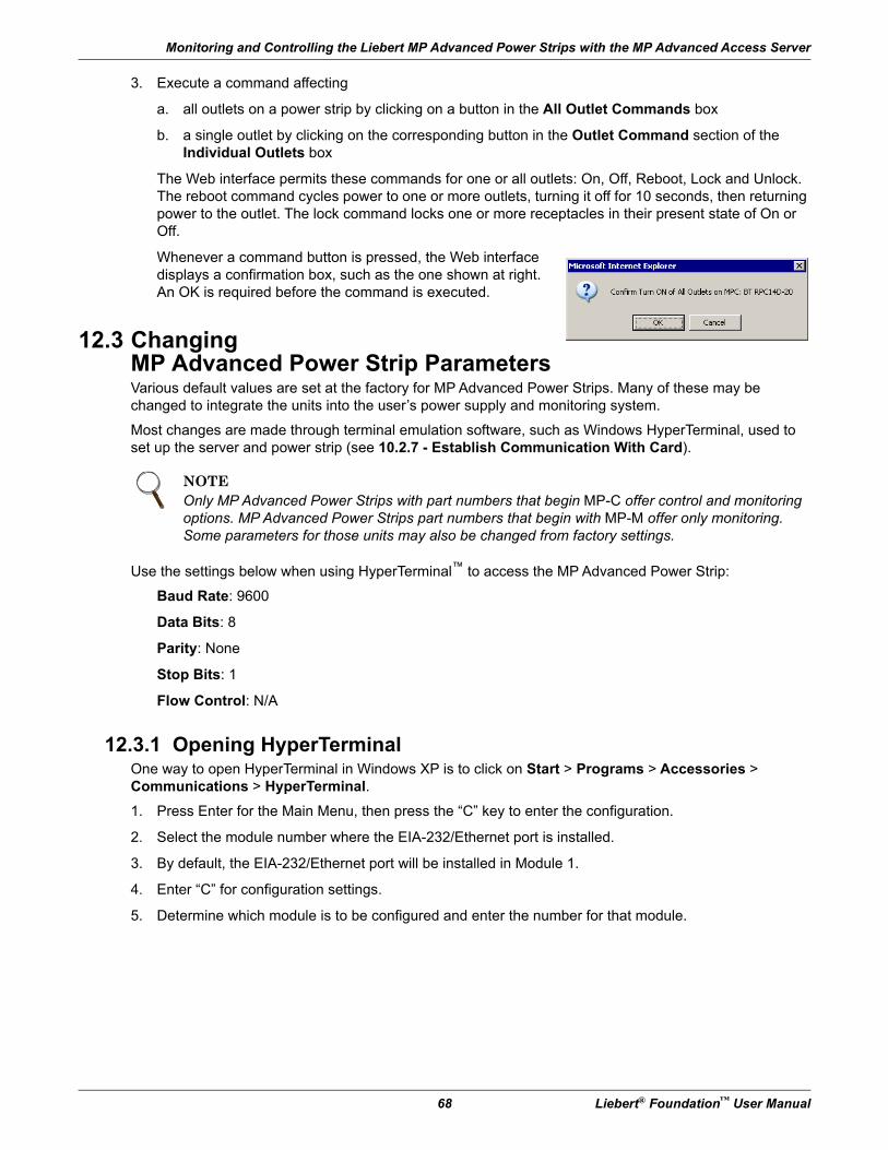
Monitoring and Controlling the Liebert MP Advanced Power Strips with the MP Advanced Access Server
68 Liebert® Foundation™ User Manual
3. Execute a command affecting
a. all outlets on a power strip by clicking on a button in the All Outlet Commands box
b. a single outlet by clicking on the corresponding button in the Outlet Command section of the Individual Outlets box
The Web interface permits these commands for one or all outlets: On, Off, Reboot, Lock and Unlock. The reboot command cycles power to one or more outlets, turning it off for 10 seconds, then returning power to the outlet. The lock command locks one or more receptacles in their present state of On or Off.
Whenever a command button is pressed, the Web interface displays a confirmation box, such as the one shown at right. An OK is required before the command is executed.
12.3 Changing MP Advanced Power Strip ParametersVarious default values are set at the factory for MP Advanced Power Strips. Many of these may be changed to integrate the units into the user’s power supply and monitoring system.
Most changes are made through terminal emulation software, such as Windows HyperTerminal, used to set up the server and power strip (see 10.2.7 - Establish Communication With Card).
Use the settings below when using HyperTerminal™ to access the MP Advanced Power Strip:
Baud Rate: 9600
Data Bits: 8
Parity: None
Stop Bits: 1
Flow Control: N/A
12.3.1 Opening HyperTerminalOne way to open HyperTerminal in Windows XP is to click on Start > Programs > Accessories > Communications > HyperTerminal.
1. Press Enter for the Main Menu, then press the “C” key to enter the configuration.
2. Select the module number where the EIA-232/Ethernet port is installed.
3. By default, the EIA-232/Ethernet port will be installed in Module 1.
4. Enter “C” for configuration settings.
5. Determine which module is to be configured and enter the number for that module.
NOTEOnly MP Advanced Power Strips with part numbers that begin MP-C offer control and monitoring options. MP Advanced Power Strips part numbers that begin with MP-M offer only monitoring. Some parameters for those units may also be changed from factory settings.
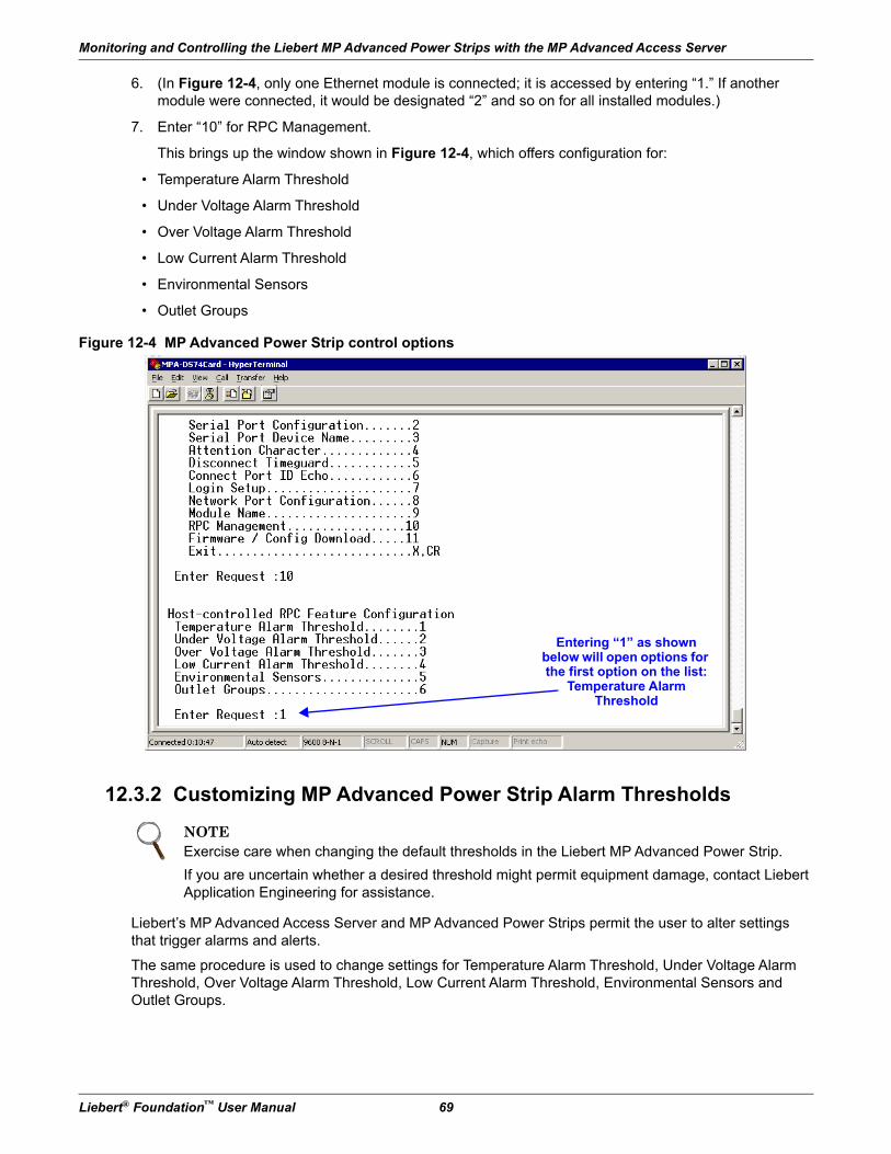
Monitoring and Controlling the Liebert MP Advanced Power Strips with the MP Advanced Access Server
Liebert® Foundation™ User Manual 69
6. (In Figure 12-4, only one Ethernet module is connected; it is accessed by entering “1.” If another module were connected, it would be designated “2” and so on for all installed modules.)
7. Enter “10” for RPC Management.
This brings up the window shown in Figure 12-4, which offers configuration for:
• Temperature Alarm Threshold
• Under Voltage Alarm Threshold
• Over Voltage Alarm Threshold
• Low Current Alarm Threshold
• Environmental Sensors
• Outlet Groups
Figure 12-4 MP Advanced Power Strip control options
12.3.2 Customizing MP Advanced Power Strip Alarm Thresholds
Liebert’s MP Advanced Access Server and MP Advanced Power Strips permit the user to alter settings that trigger alarms and alerts.
The same procedure is used to change settings for Temperature Alarm Threshold, Under Voltage Alarm Threshold, Over Voltage Alarm Threshold, Low Current Alarm Threshold, Environmental Sensors and Outlet Groups.
NOTEExercise care when changing the default thresholds in the Liebert MP Advanced Power Strip.
If you are uncertain whether a desired threshold might permit equipment damage, contact Liebert Application Engineering for assistance.
Entering “1” as shown below will open options for the first option on the list:
Temperature Alarm Threshold
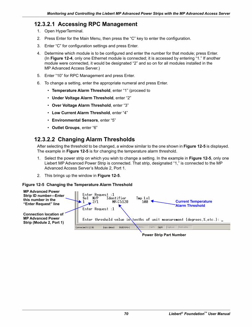
Monitoring and Controlling the Liebert MP Advanced Power Strips with the MP Advanced Access Server
70 Liebert® Foundation™ User Manual
12.3.2.1 Accessing RPC Management1. Open HyperTerminal.
2. Press Enter for the Main Menu, then press the “C” key to enter the configuration.
3. Enter “C” for configuration settings and press Enter.
4. Determine which module is to be configured and enter the number for that module; press Enter.(In Figure 12-4, only one Ethernet module is connected; it is accessed by entering “1.” If another module were connected, it would be designated “2” and so on for all modules installed in the MP Advanced Access Server.)
5. Enter “10” for RPC Management and press Enter.
6. To change a setting, enter the appropriate numeral and press Enter.
• Temperature Alarm Threshold, enter “1” (proceed to
• Under Voltage Alarm Threshold, enter “2”
• Over Voltage Alarm Threshold, enter “3”
• Low Current Alarm Threshold, enter “4”
• Environmental Sensors, enter “5”
• Outlet Groups, enter “6”
12.3.2.2 Changing Alarm ThresholdsAfter selecting the threshold to be changed, a window similar to the one shown in Figure 12-5 is displayed. The example in Figure 12-5 is for changing the temperature alarm threshold.
1. Select the power strip on which you wish to change a setting. In the example in Figure 12-5, only one Liebert MP Advanced Power Strip is connected. That strip, designated “1,” is connected to the MP Advanced Access Server’s Module 2, Port 1.
2. This brings up the window in Figure 12-5.
Figure 12-5 Changing the Temperature Alarm Threshold
MP Advanced Power Strip ID number—Enter this number in the “Enter Request” line
Connection location of MP Advanced Power Strip (Module 2, Port 1)
Current Temperature Alarm Threshold
Power Strip Part Number
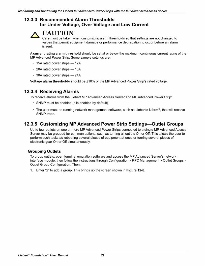
Monitoring and Controlling the Liebert MP Advanced Power Strips with the MP Advanced Access Server
Liebert® Foundation™ User Manual 71
12.3.3 Recommended Alarm Thresholds for Under Voltage, Over Voltage and Low Current
A current rating alarm threshold should be set at or below the maximum continuous current rating of the MP Advanced Power Strip. Some sample settings are:
• 15A rated power strips — 12A
• 20A rated power strips — 16A
• 30A rated power strips — 24A
Voltage alarm thresholds should be ±10% of the MP Advanced Power Strip’s rated voltage.
12.3.4 Receiving AlarmsTo receive alarms from the Liebert MP Advanced Access Server and MP Advanced Power Strip:
• SNMP must be enabled (it is enabled by default)
• The user must be running network management software, such as Liebert’s Nform®, that will receive SNMP traps.
12.3.5 Customizing MP Advanced Power Strip Settings—Outlet GroupsUp to four outlets on one or more MP Advanced Power Strips connected to a single MP Advanced Access Server may be grouped for common actions, such as turning all outlets On or Off. This allows the user to perform such tasks as rebooting several pieces of equipment at once or turning several pieces of electronic gear On or Off simultaneously.
Grouping OutletsTo group outlets, open terminal emulation software and access the MP Advanced Server’s network interface module, then follow the instructions through Configuration > RPC Management > Outlet Groups > Outlet Group Configuration. Then:
1. Enter “2” to add a group. This brings up the screen shown in Figure 12-6.
! CAUTIONCare must be taken when customizing alarm thresholds so that settings are not changed to values that permit equipment damage or performance degradation to occur before an alarm is sent.
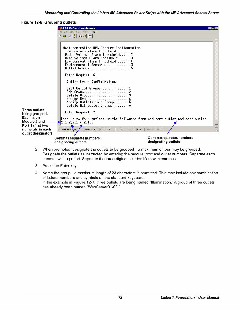
Monitoring and Controlling the Liebert MP Advanced Power Strips with the MP Advanced Access Server
72 Liebert® Foundation™ User Manual
Figure 12-6 Grouping outlets
2. When prompted, designate the outlets to be grouped—a maximum of four may be grouped.Designate the outlets as instructed by entering the module, port and outlet numbers. Separate each numeral with a period. Separate the three-digit outlet identifiers with commas.
3. Press the Enter key.
4. Name the group—a maximum length of 23 characters is permitted. This may include any combination of letters, numbers and symbols on the standard keyboard.In the example in Figure 12-7, three outlets are being named “Illumination.” A group of three outlets has already been named “WebServer01-03.”
Three outlets being grouped. Each is onModule 2 andPort 1 (first two numerals in each outlet designator)
Commas separate numbers designating outlets
Comma separates numbers designating outlets
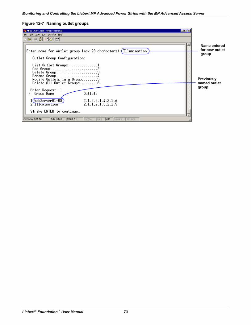
Monitoring and Controlling the Liebert MP Advanced Power Strips with the MP Advanced Access Server
Liebert® Foundation™ User Manual 73
Figure 12-7 Naming outlet groups
Name entered for new outlet group
Previously named outlet group
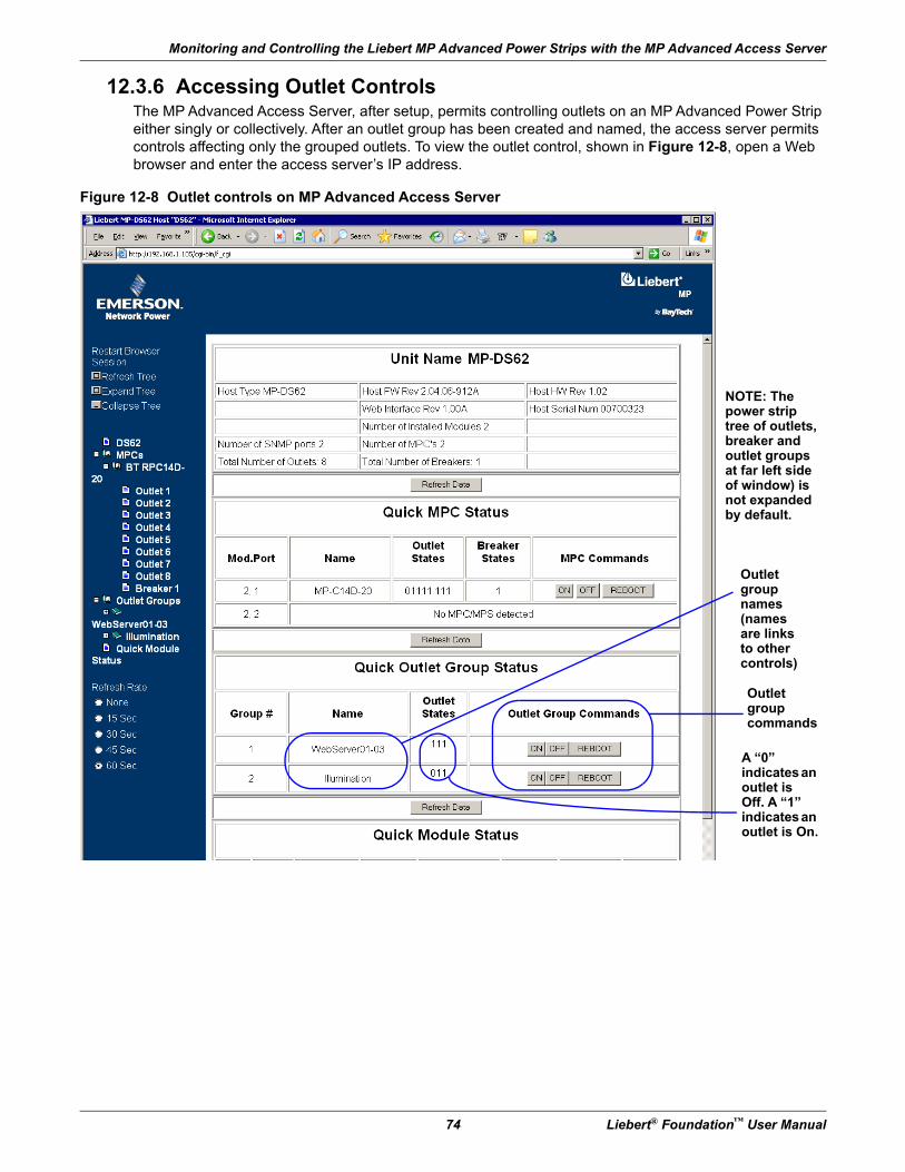
Monitoring and Controlling the Liebert MP Advanced Power Strips with the MP Advanced Access Server
74 Liebert® Foundation™ User Manual
12.3.6 Accessing Outlet ControlsThe MP Advanced Access Server, after setup, permits controlling outlets on an MP Advanced Power Strip either singly or collectively. After an outlet group has been created and named, the access server permits controls affecting only the grouped outlets. To view the outlet control, shown in Figure 12-8, open a Web browser and enter the access server’s IP address.
Figure 12-8 Outlet controls on MP Advanced Access Server
Outlet group names (names are links to other controls)
Outlet groupcommands
NOTE: The power strip tree of outlets, breaker and outlet groups at far left side of window) is not expanded by default.
A “0”indicates an outlet is Off. A “1” indicates an outlet is On.
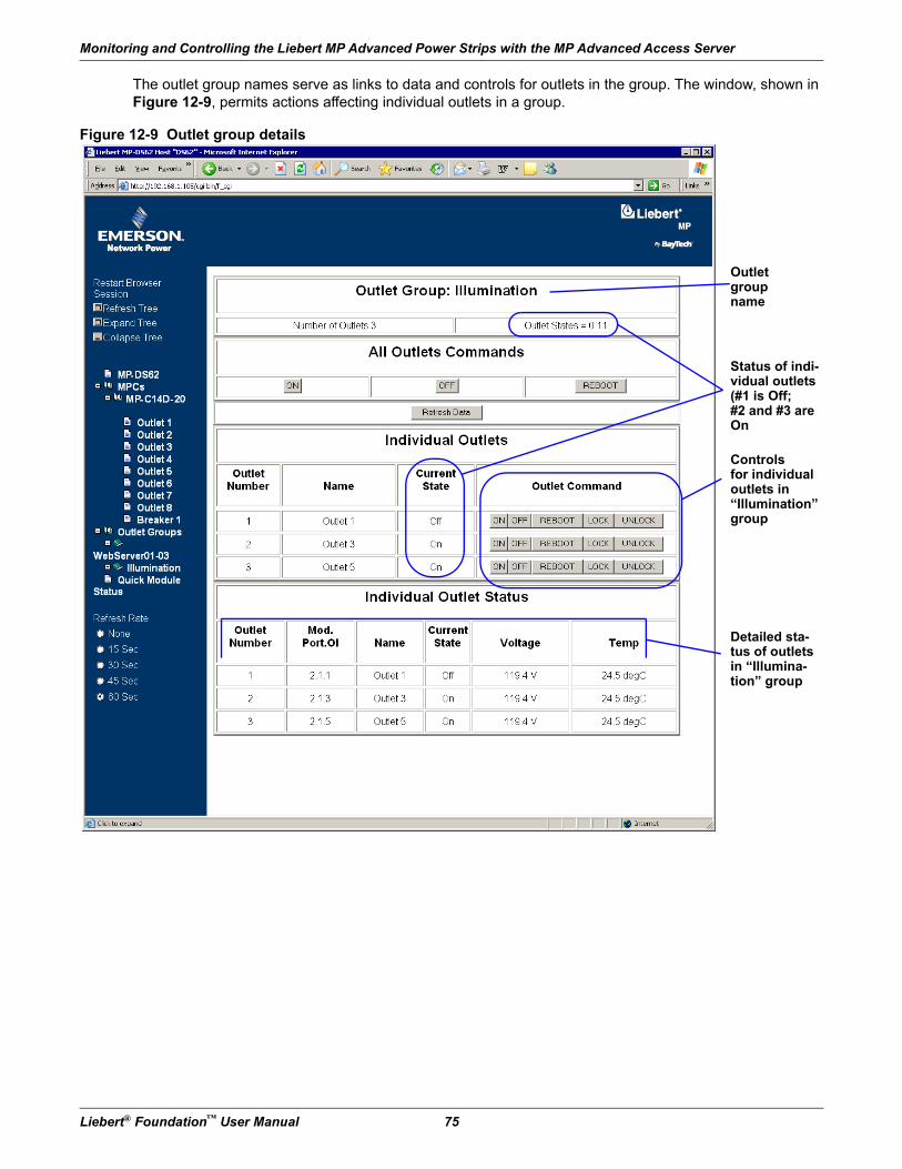
Monitoring and Controlling the Liebert MP Advanced Power Strips with the MP Advanced Access Server
Liebert® Foundation™ User Manual 75
The outlet group names serve as links to data and controls for outlets in the group. The window, shown in Figure 12-9, permits actions affecting individual outlets in a group.
Figure 12-9 Outlet group details
Outlet group name
Controlsfor individualoutlets in“Illumination” group
Detailed sta-tus of outlets in “Illumina-tion” group
Status of indi-vidual outlets (#1 is Off;#2 and #3 are On
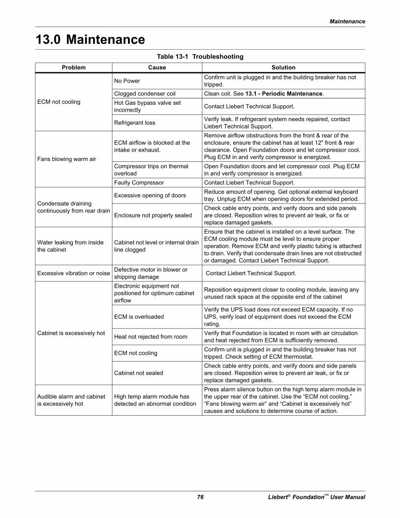
Maintenance
76 Liebert® Foundation™ User Manual
13.0 MaintenanceTable 13-1 Troubleshooting
Problem Cause Solution
ECM not cooling
No PowerConfirm unit is plugged in and the building breaker has not tripped.
Clogged condenser coil Clean coil. See 13.1 - Periodic Maintenance.
Hot Gas bypass valve set incorrectly
Contact Liebert Technical Support.
Refrigerant lossVerify leak. If refrigerant system needs repaired, contact Liebert Technical Support.
Fans blowing warm air
ECM airflow is blocked at the intake or exhaust.
Remove airflow obstructions from the front & rear of the enclosure, ensure the cabinet has at least 12" front & rear clearance. Open Foundation doors and let compressor cool. Plug ECM in and verify compressor is energized.
Compressor trips on thermal overload
Open Foundation doors and let compressor cool. Plug ECM in and verify compressor is energized.
Faulty Compressor Contact Liebert Technical Support.
Condensate drainingcontinuously from rear drain
Excessive opening of doorsReduce amount of opening. Get optional external keyboard tray. Unplug ECM when opening doors for extended period.
Enclosure not properly sealedCheck cable entry points, and verify doors and side panels are closed. Reposition wires to prevent air leak, or fix or replace damaged gaskets.
Water leaking from inside the cabinet
Cabinet not level or internal drain line clogged
Ensure that the cabinet is installed on a level surface. The ECM cooling module must be level to ensure proper operation. Remove ECM and verify plastic tubing is attached to drain. Verify that condensate drain lines are not obstructed or damaged. Contact Liebert Technical Support.
Excessive vibration or noiseDefective motor in blower or shipping damage
Contact Liebert Technical Support.
Cabinet is excessively hot
Electronic equipment not positioned for optimum cabinet airflow
Reposition equipment closer to cooling module, leaving any unused rack space at the opposite end of the cabinet
ECM is overloadedVerify the UPS load does not exceed ECM capacity. If no UPS, verify load of equipment does not exceed the ECM rating.
Heat not rejected from roomVerify that Foundation is located in room with air circulation and heat rejected from ECM is sufficiently removed.
ECM not coolingConfirm unit is plugged in and the building breaker has not tripped. Check setting of ECM thermostat.
Cabinet not sealedCheck cable entry points, and verify doors and side panels are closed. Reposition wires to prevent air leak, or fix or replace damaged gaskets.
Audible alarm and cabinet is excessively hot
High temp alarm module has detected an abnormal condition
Press alarm silence button on the high temp alarm module in the upper rear of the cabinet. Use the “ECM not cooling,” “Fans blowing warm air” and “Cabinet is excessively hot” causes and solutions to determine course of action.
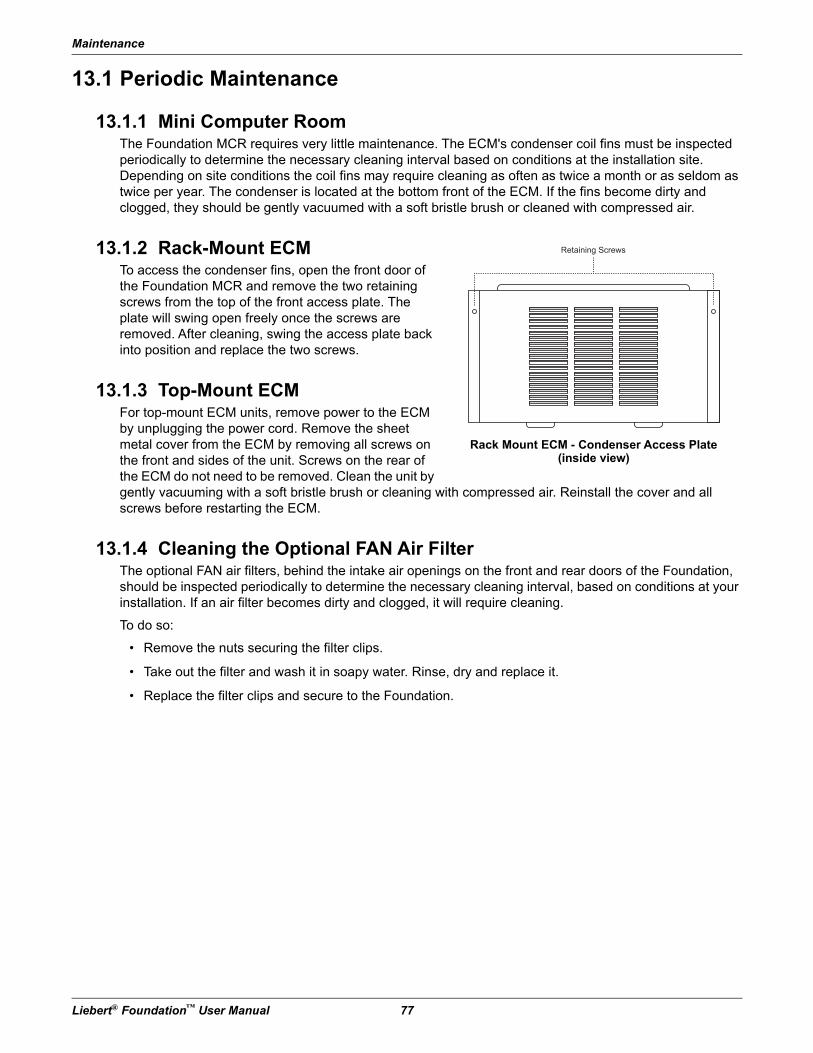
Maintenance
Liebert® Foundation™ User Manual 77
13.1 Periodic Maintenance
13.1.1 Mini Computer RoomThe Foundation MCR requires very little maintenance. The ECM's condenser coil fins must be inspected periodically to determine the necessary cleaning interval based on conditions at the installation site. Depending on site conditions the coil fins may require cleaning as often as twice a month or as seldom as twice per year. The condenser is located at the bottom front of the ECM. If the fins become dirty and clogged, they should be gently vacuumed with a soft bristle brush or cleaned with compressed air.
13.1.2 Rack-Mount ECMTo access the condenser fins, open the front door of the Foundation MCR and remove the two retaining screws from the top of the front access plate. The plate will swing open freely once the screws are removed. After cleaning, swing the access plate back into position and replace the two screws.
13.1.3 Top-Mount ECMFor top-mount ECM units, remove power to the ECM by unplugging the power cord. Remove the sheet metal cover from the ECM by removing all screws on the front and sides of the unit. Screws on the rear of the ECM do not need to be removed. Clean the unit by gently vacuuming with a soft bristle brush or cleaning with compressed air. Reinstall the cover and all screws before restarting the ECM.
13.1.4 Cleaning the Optional FAN Air FilterThe optional FAN air filters, behind the intake air openings on the front and rear doors of the Foundation, should be inspected periodically to determine the necessary cleaning interval, based on conditions at your installation. If an air filter becomes dirty and clogged, it will require cleaning.
To do so:
• Remove the nuts securing the filter clips.
• Take out the filter and wash it in soapy water. Rinse, dry and replace it.
• Replace the filter clips and secure to the Foundation.
Rack Mount ECM - Condenser Access Plate (inside view)
Maintenance
78 Liebert® Foundation™ User Manual
13.2 MCR Start-Up Inspection Checklist
13.2.1 Site Conditions___ 1. Confirm at least 1 ft. (0.3m) clearance in front & behind the unit. No side clearance required.
___ 2. Confirm at least 1 ft. (0.3m) clearance above the top of the unit.
___ 3. Confirm service clearances: 3 ft. (1m) enclosure front, or provisions to move enclosure to allow for service access.
___ 4. Confirm site ventilation provisions: ECM is self-contained air-cooled system.
____Sufficient ambient space to dissipate heat rejected by the ECM.
Ambient temperature range is 65°F (18°C) to 105°F (40°C).
____If equipped with Heat Rejection Fan or Duct option, confirm electrical connection.
___ 5. Confirm that the ECM cooling module is level withing 1/4 inch from front-to-rear and side-to-side.
___ 6. Confirm ECM condensate drain tube is routed out the back of the unit, flex tube is clear and not kinked.
___ 7. Confirm separate dedicated circuits for ECM & UPS are provided (not same duplex).
____ECMs require a 120V/60Hz/15A, single-phase 2-wire plus ground circuit.
____Check UPS (if provided) nameplate for input electrical requirements.
13.2.2 Unit Start-Up and Operation___ 1. Confirm no ECM airflow obstructions:
____External (1 ft. / 0.3m minimum clearance): Enclosure front, rear and top.
____Internal: ECM discharge and return. Obstructions include manuals, cables, equipment overhanging shelves, etc.
___ 2. Examine the positioning of equipment inside the cabinet.
____Prevent short cycling of ECM airflow - no large spaces between electronic devices in the top and bottom of the cabinet.
____Equipment with the highest heat load should be located as close to the ECM as possible.
____Heaviest equipment installed near the bottom of the cabinet.
___ 3. Power up ECM: Apply power via the external cord/plug connection.
____Confirm immediate internal ECM airflow: Inside enclosure, ECM right side (evap. discharge).
____Confirm compressor engages within two minutes (return air must be > 75°F to start compressor).
___ 4. Record the ECM working input voltage 120VAC (+10%): ____________________
___ 5. Power up UPS (if provided). Record the UPS working input voltage (separate circuit): ____________________
___ 6. Check Cabinet Seals—No gaps, loose cables, air leaks:
____Door gaskets intact / free of damage. Close front & rear doors and confirm no visible seal violations.
____Side panels and the frame have uniform sealing.
____Cable entrance points are sealed.
Installation Drawings
Liebert® Foundation™ User Manual 79
14.0 Installation Drawings
Figure 14-1 Foundation 12U low profile wall-mount dimensions and features
Adju
sta
ble
depth
and h
eig
ht
sid
e face m
ounting r
ails
(6U
)
Adju
sta
ble
depth
fro
nt fa
ce
mounting r
ails
(12U
)
3.5
" (9
4m
m)
16"
(406m
m)
16"
(406m
m)
12.5
5"
(319m
m)
13.3
4"
(339m
m)
201780 R
ev.
2
5.4
1"
(137.4
mm
)
.44”
(11m
m)
typ.
1.0
6”
(27m
m)
typ.
26.5
2"
(674m
m)
23.3
8"
(594m
m)
O
O
Installation Drawings
80 Liebert® Foundation™ User Manual
Figure 14-2 Foundation 12U hinged body wall-mount dimensions and features
O
O
Adju
sta
ble
depth
fro
nt fa
ce
19"
(483m
m)
mounting r
ails
(12U
)
(sid
e p
anel not show
n for
cla
rity
)
24.2
7"
(616m
m)
26.1
2"
(663m
m)
3.5
"
(89m
m)
3.7
9"
(96m
m)
3.5
7"
(91m
m)
16"
(406m
m)
2"
(51m
m)
knockouts
- 8
16"
(406m
m)
.44"
(11m
m)
typ.
1.0
6"
(27m
m)
typ.
26.9
2"
(684m
m)
23.5
8"
(599m
m)
22.9
"
(582m
m)
201767 R
ev.
2
Installation Drawings
Liebert® Foundation™ User Manual 81
Figure 14-3 Foundation 22U frame dimensions and features
F-K
22
x0
-00
0
Re
v.
0
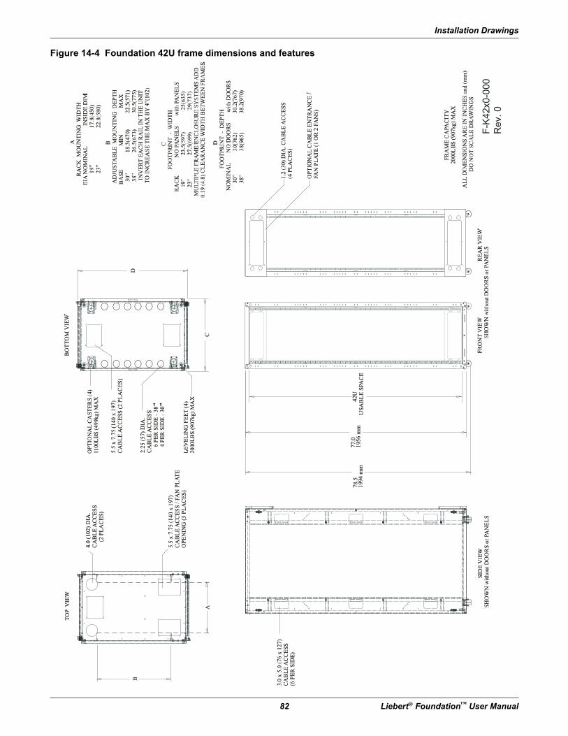
Installation Drawings
82 Liebert® Foundation™ User Manual
Figure 14-4 Foundation 42U frame dimensions and features
F-K
42x0-0
00
Rev. 0
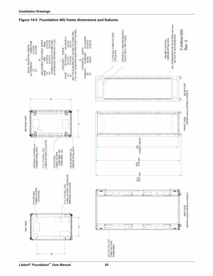
Installation Drawings
Liebert® Foundation™ User Manual 83
Figure 14-5 Foundation 46U frame dimensions and features
F-K
46x0-0
00
Rev. 0
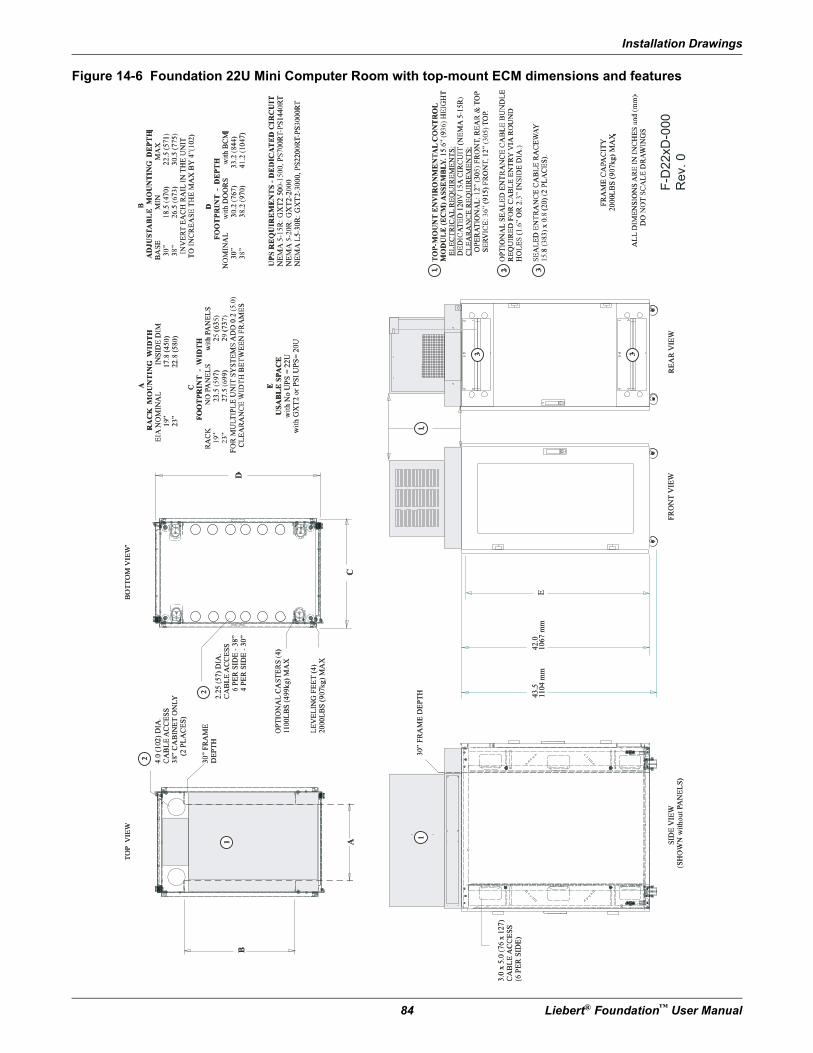
Installation Drawings
84 Liebert® Foundation™ User Manual
Figure 14-6 Foundation 22U Mini Computer Room with top-mount ECM dimensions and features
F-D
22xD
-000
Rev. 0
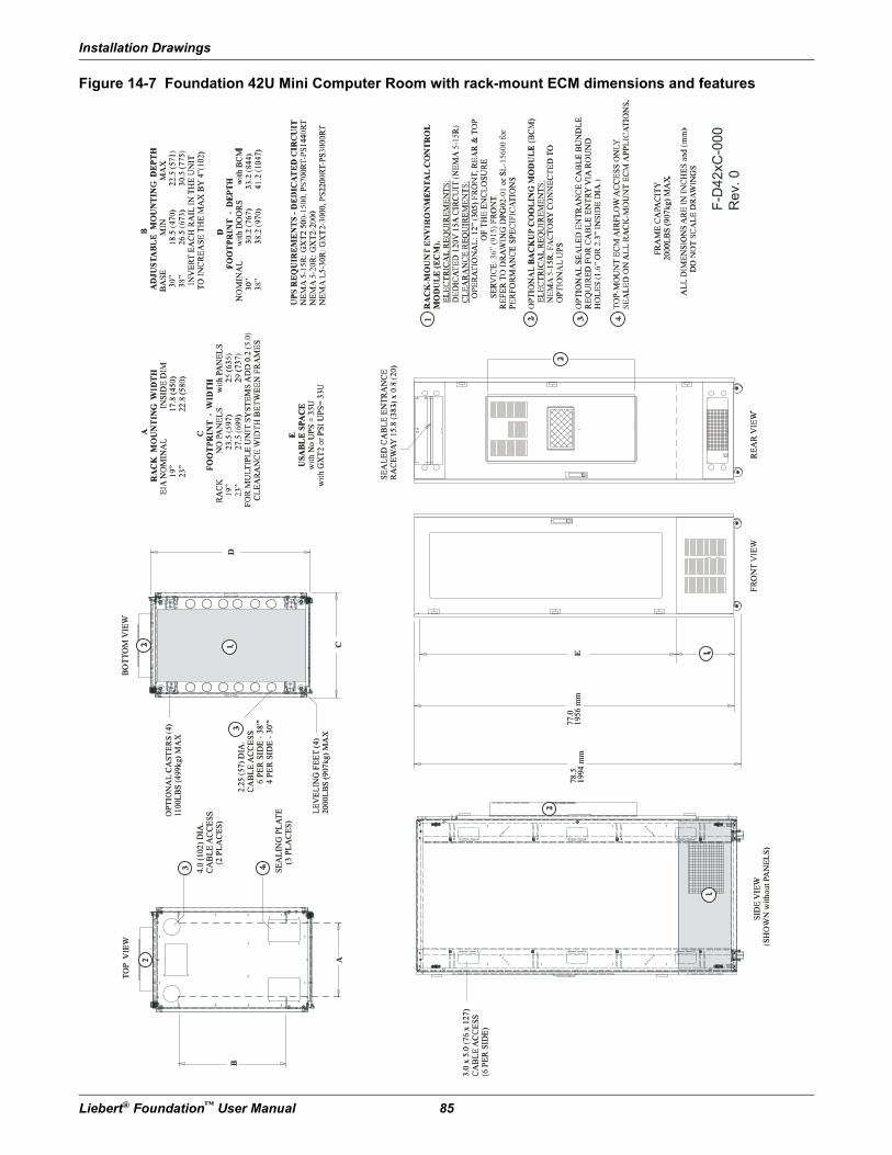
Installation Drawings
Liebert® Foundation™ User Manual 85
Figure 14-7 Foundation 42U Mini Computer Room with rack-mount ECM dimensions and features
F-D
42xC
-000
Rev. 0
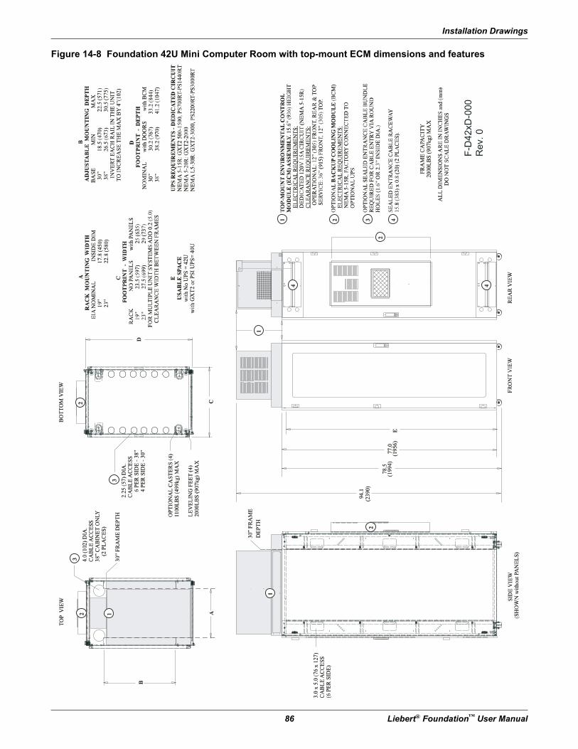
Installation Drawings
86 Liebert® Foundation™ User Manual
Figure 14-8 Foundation 42U Mini Computer Room with top-mount ECM dimensions and features
F-D
42
xD
-00
0
Re
v.
0
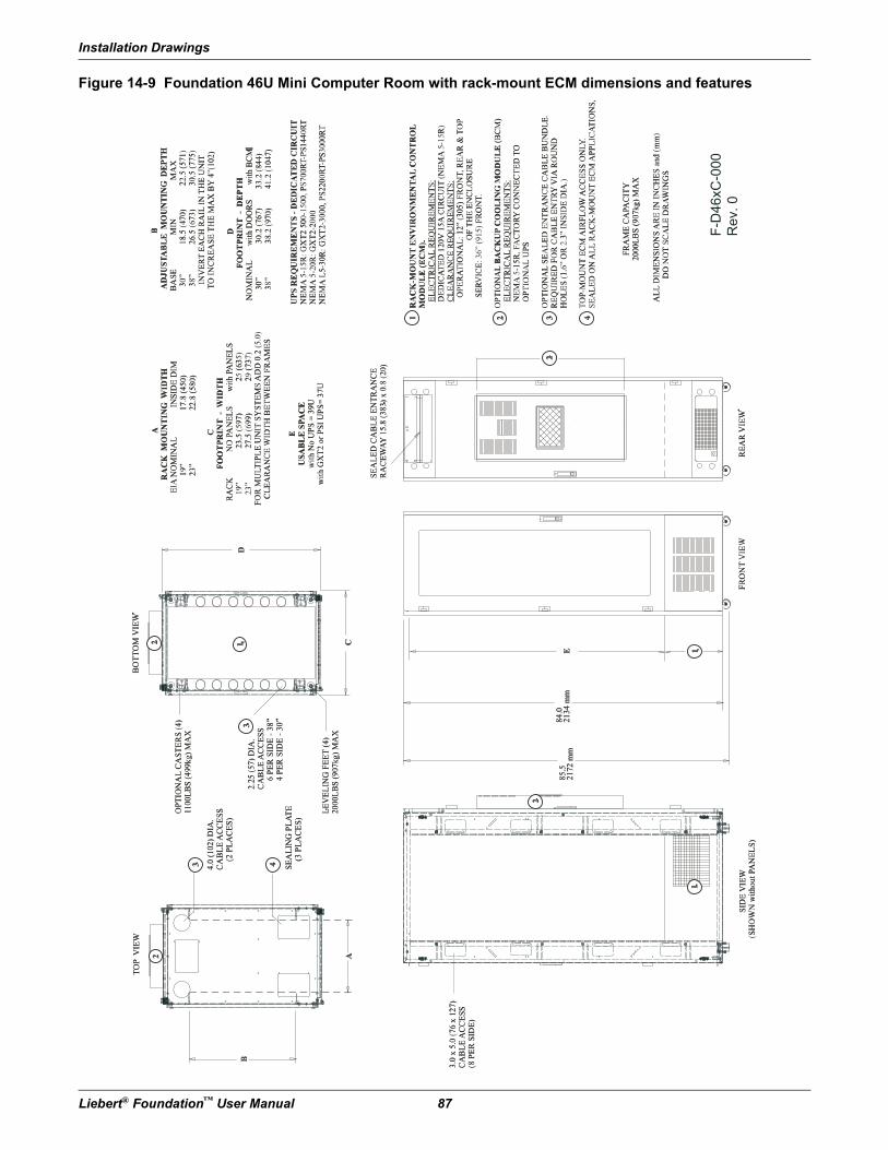
Installation Drawings
Liebert® Foundation™ User Manual 87
Figure 14-9 Foundation 46U Mini Computer Room with rack-mount ECM dimensions and features
F-D
46xC
-000
Rev. 0
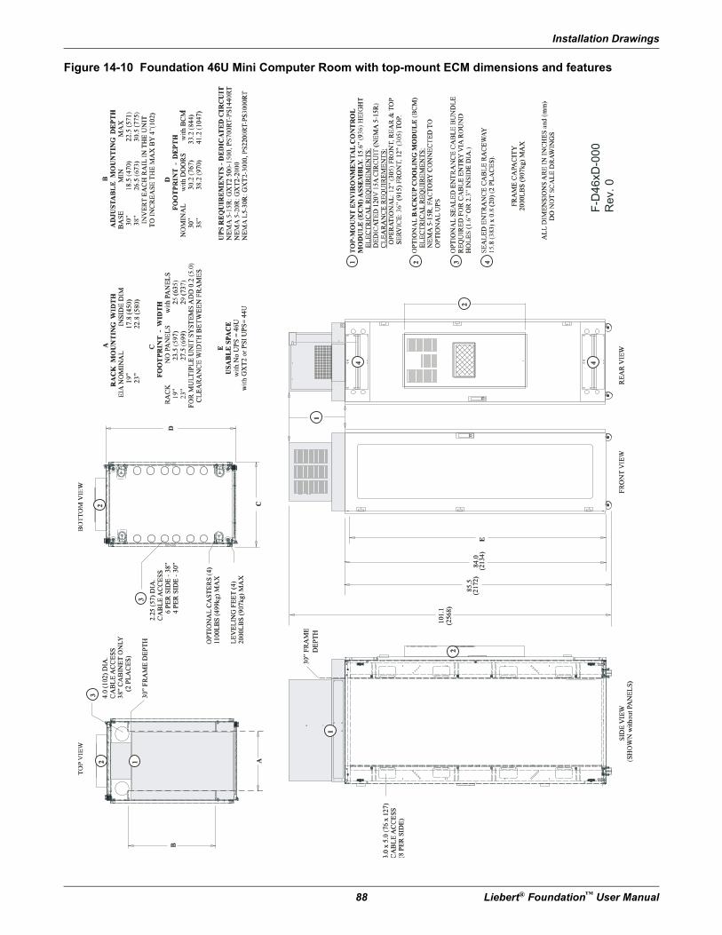
Installation Drawings
88 Liebert® Foundation™ User Manual
Figure 14-10 Foundation 46U Mini Computer Room with top-mount ECM dimensions and features
F-D
46
xD
-00
0
Re
v.
0
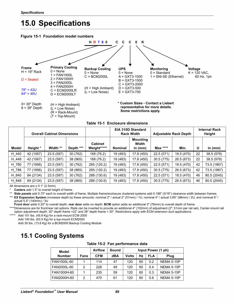
Specifications
Liebert® Foundation™ User Manual 89
15.0 Specifications
Figure 15-1 Foundation model numbers
15.1 Cooling Systems
Table 15-1 Enclosure dimensions
Model
Overall Cabinet DimensionsEIA 310D Standard
Rack Width Adjustable Rack DepthInternal Rack
Height
Height * Width ** Depth ***Cabinet
Weight***** Nominal
MountingWidth
in (mm) Max **** Min. U in (mm)
H_440 42 (1067) 23.5 (597) 30 (762) 168 (76.2) 19 (483) 17.8 (450) 22.5 (571) 18.5 (470) 22 38.5 (978)
H_448 42 (1067) 23.5 (597) 38 (965) 168 (76.2) 19 (483) 17.8 (450) 30.5 (775) 26.5 (673) 22 38.5 (978)
H_780 77 (1956) 23.5 (597) 30 (762) 265 (120.2) 19 (483) 17.8 (450) 22.5 (571) 18.5 (470) 42 73.5 (1867)
H_788 77 (1956) 23.5 (597) 38 (965) 265 (120.2) 19 (483) 17.8 (450) 30.5 (775) 26.5 (673) 42 73.5 (1867)
H_840 84 (2134) 23.5 (597) 30 (762) 288 (130.6) 19 (483) 17.8 (450) 22.5 (571) 18.5 (470) 46 80.5 (2045)
H_848 84 (2134) 23.5 (597) 38 (965) 288 (130.6) 19 (483) 17.8 (450) 30.5 (775) 26.5 (673) 46 80.5 (2045)
All dimensions are ± 0.1" (2.5mm)* Casters add 1.5" to overall height of frame.** Side panels add 0.75" each to overall width of frame. Multiple frame/enclosure clustered systems add 0.188" (3/16”) clearance width between frames.*** EX Expansion System increases depth by these amounts: nominal 2" / actual 2" (51mm) / 1U; nominal 4" / actual 3.85" (98mm) / 2U; and nominal 6" /
actual 5.5" (140mm) / 3UFront door adds 0.25" to overall depth; rear door adds no depth; BCM option adds an additional 3" (76mm) to overall depth of frame.
****Dimensions are for front/rear rail options. Rails can be inverted to provide an additional 4" (102mm) of adjustment (2"; 51mm per rail set). Center-mount rail option adjustment depth: 30" depth frame =22” and 38" depth frame = 30". Restrictions apply with ECM extension duct applications.
***** Add 101 lbs. (45.8 Kg) for a rack-mount ECM 2000 Add 140 lbs. (63.5 Kg) for a top-mount ECM2000 Add 30 lbs. (13.6 Kg) for a BCM2000 Backup Cooling Module
Table 15-2 Fan performance data
ModelNumber Fans
Airflow Sound Input Power (1 ph)
CFM dBA Volts Hz FLA Plug
FAN1000L-60 1 114 47 120 60 0.2 NEMA 5-15P
FAN2000L-60 2 228 49 120 60 0.4 NEMA 5-15P
FAN1000H-60 1 235 59 120 60 0.3 NEMA 5-15P
FAN2000H-60 2 470 61 120 60 0.6 NEMA 5-15P
H D 7 8 0
FrameH = 19" Rack
D = Sealed
78" = 42U84" = 46U
0= 30" Depth8 = 38" Depth
Primary Cooling0 = None1 = FAN1000L2 = FAN1000H3 = FAN2000L4 = FAN2000HC = ECM2000LRD = ECM2000LT
(H = High Ambient)(L = Low Noise)(R = Rack-Mount)(T = Top-Mount)
Backup Cooling0 = NoneC = BCM2000L
(H = High Ambient)(L = Low Noise)
UPS0 = NoneA = GXT3-1000B = GXT3-1500C = GXT3-2000D = GXT3-500E = GXT3-700
Monitoring0 = Standard1 = SNI-SE (Ethernet)
* Custom Sizes - Contact a Liebert representative for more details. Some restrictions apply.
C C C 0 K
VoltageK = 120 VAC,
60 Hz, 1ph
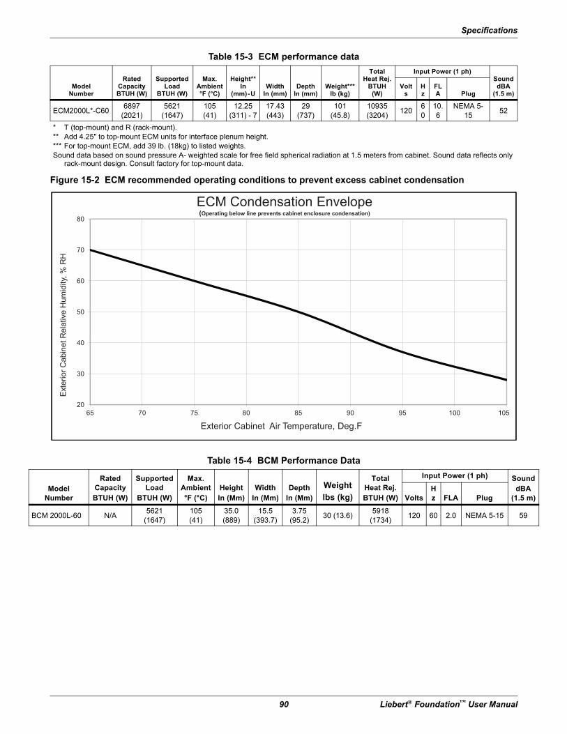
Specifications
90 Liebert® Foundation™ User Manual
Figure 15-2 ECM recommended operating conditions to prevent excess cabinet condensation
Table 15-3 ECM performance data
ModelNumber
RatedCapacityBTUH (W)
SupportedLoad
BTUH (W)
Max.Ambient°F (°C)
Height**In
(mm)-UWidth
In (mm)Depth
In (mm)Weight***
lb (kg)
TotalHeat Rej.
BTUH(W)
Input Power (1 ph)SounddBA
(1.5 m)Volt
sHz
FLA Plug
ECM2000L*-C606897
(2021)5621
(1647)105(41)
12.25(311) - 7
17.43(443)
29(737)
101(45.8)
10935(3204)
12060
10.6
NEMA 5-15
52
* T (top-mount) and R (rack-mount).** Add 4.25" to top-mount ECM units for interface plenum height.*** For top-mount ECM, add 39 lb. (18kg) to listed weights.Sound data based on sound pressure A- weighted scale for free field spherical radiation at 1.5 meters from cabinet. Sound data reflects only
rack-mount design. Consult factory for top-mount data.
Table 15-4 BCM Performance Data
ModelNumber
RatedCapacityBTUH (W)
SupportedLoad
BTUH (W)
Max.Ambient°F (°C)
HeightIn (Mm)
WidthIn (Mm)
DepthIn (Mm)
Weight
lbs (kg)
TotalHeat Rej.BTUH (W)
Input Power (1 ph) SounddBA
(1.5 m)VoltsHz FLA Plug
BCM 2000L-60 N/A5621
(1647)105(41)
35.0(889)
15.5(393.7)
3.75(95.2)
30 (13.6)5918
(1734)120 60 2.0 NEMA 5-15 59
50
60
70
80
Rela
tive H
um
idity,
% R
H
ECM Condensation Envelope(Operating below line prevents cabinet enclosure condensation)
20
30
40
65 70 75 80 85 90 95 100 105
Exte
rio
r C
ab
ine
t
Exterior Cabinet Air Temperature, Deg.F
Specifications
Liebert® Foundation™ User Manual 91
15.2 Power SystemsTable 15-5 UPS Performance Data
ModelNumber VA / Watts
Height
In (mm) U
Input Power (1 ph)
Volts OPD (A) Plug
GXT2-700RT120 700 / 490 3.5 (89) 2 120 15 NEMA 5-15P
GXT2-1000RT120 1000 / 700 3.5 (89) 2 120 15 NEMA 5-15P
GXT2-1500RT120 1500 / 1050 3.5 (89) 2 120 15 NEMA 5-15P
GXT2-2000RT120 2000 / 1400 3.5 (89) 2 120 20 NEMA 5-20P
GXT2-3000RT120 3000 / 2100 3.5 (89) 2 120 30 NEMA L5-30P
GXT2-700RT230 700 / 490 3.5 (89) 2 230 10 IEC-C14 *
GXT2-1000RT230 1000 / 700 3.5 (89) 2 230 10 IEC-C14 *
GXT2-1500RT230 1500 / 1050 3.5 (89) 2 230 10 IEC-C14 *
GXT2-2000RT230 2000 / 1400 3.5 (89) 2 230 10 IEC-C14 *
GXT2-3000RT230 3000 / 2100 3.5 (89) 2 230 16 IEC-C20 *
GXT5000R-208 5000 / 3750 10.5 (267) 6 208 30 NEMA L6-30
GXT2-6000RT-208 6000 / 4200 7 (178) 4 208/240 30NEMA L14-30or Hard-Wired
PS1000RT2-120 1000 / 750 3.5 (89) 2 120 15 NEMA 5-15P
PS1440RT2-120 1440 / 1080 3.5 (89) 2 120 15 NEMA 5-15P
PS2200RT2-120 2200 / 1650 3.5 (89) 2 120 15 NEMA L5-30P
PS3000RT2-120 3000 / 2250 3.5 (89) 2 120 15 NEMA L5-30P
PS1000RT2-230 1000 / 750 3.5 (89) 2 230 15 IEC-C14 *
PS1440RT2-230 1440 / 1080 3.5 (89) 2 230 15 IEC-C14 *
PS2200RT2-230 2200 / 1650 3.5 (89) 2 230 15 IEC-C20 *
PS3000RT2-230 3000 / 2250 3.5 (89) 2 230 15 IEC-C20 *
* All 230V models are equipped with input sockets for use with detachable cords. Input cords are not provided, however each unit does include two 1.8m 10A load cords.
Specifications
92 Liebert® Foundation™ User Manual
15.3 Optional Managed Power - Advanced Power Strips, Vertical- or Horizontal-MountMP Advanced Power Strips are available in 19" rack-mount and vertical-mount form to accommodate different installation requirements. See Mounting Method & Size in Table 15-6 for specific configurations.
Table 15-6 MP Advanced Power Strip specifications
Liebert PN
MountingMethod& Size
Input Output
Envir.Port
Voltage-Current (A)-
PhaseConnectionType (Quan)
CordLength,Ft. (m)
Voltage-Current (A)-
PhaseConnection
Type(s) (Quan)
Remote Monitoring and Control
MP-C5120 Rckmnt/1U 120V-15A-1ph 5-15P (1) 6 (1.8) 120V-15A-1ph 5-15/20R (8) 0
MP-C5121 Rckmnt /1U 120V-20A-1ph 5-20P (1) 6 (1.8) 120V-20A-1ph 5-15/20R (8) 0
MP-C5122 Rckmnt/1U 120V-20A-1ph L5-20P (1) 6 (1.8) 120V-20A-1ph 5-15/20R (8) 0
MP-C5123 Rckmnt/1U 120V-30A-1ph L5-30P (1) 6 (1.8) 120V-30A-1ph 5-15/20R (8) 2
MP-C5124 Rckmnt/1U 200/240V-20A-1ph L6-20P (1) 6 (1.8) 200/240V-20A-1ph IEC320 C13 (8) 0
MP-C5125 Rckmnt/1U 200/240V-30A-1ph L6-30P (1) 6 (1.8) 200/240V-30A-1ph IEC320 C13 (8) 2
MP-C5147 Vert. / 68.18" 120V-20A-1ph 5-20P (1) 10 (3) 120V-20A-1ph 5-15/20R (21*) 2
MP-C5148 Vert. / 68.18" 120V-20A-1ph L5-20P (1) 10 (3) 120V-20A-1ph 5-15/20R (21*) 2
MP-C5131 Vert. / 68.18" 120V-30A-1ph L5-30P (1) 10 (3) 120V-30A-1ph 5-15/20R (21*) 2
MP-C5132 Vert. / 68.18" 200/240V-20A-1ph L6-20P (1) 10 (3) 200/240V-20A-1ph IEC320 C13 (21*) 2
MP-C5133 Vert. / 68.18" 200/240V-30A-1ph L6-30P (1) 10 (3) 200/240V-30A-1ph IEC320 C13 (21*) 2
MP-C5134 Vert. / 68.18" 120/208V-20A-3ph L21-20P (1) 10 (3) 120V-20A-1ph 5-15/20R (21*) 2
MP-C5135 Vert. / 68.18" 120/208V-20A-3ph L21-20P (1) 10 (3) 3 ph/208V-20A-1phNEMA L21-20 (1)
+ IEC320 C13 (18)2
MP-C5136 Vert. / 68.18" 120/208V-30A-3ph L21-30P (1) 10 (3) 3 ph/208V-30A-1phNEMA L21-20 (1)
+ IEC320 C13 (18)2
Remote Monitoring Only
MP-M5109 Rckmnt/1U 120V-15A-1ph 5-15P (1) 6 (1.8) 120V-15A-1ph 5-15/20R (10) 2
MP-M5110 Rckmnt/1U 120V-20A-1ph 5-20P (1) 6 (1.8) 120V-20A-1ph 5-15/20R (10) 2
MP-M5111 Rckmnt/1U 120V-20A-1ph L5-20P (1) 6 (1.8) 120V-20A-1ph 5-15/20R (10) 2
MP-M5112 Rckmnt/1U 120V-30A-1ph L5-30P (1) 6 (1.8) 120V-30A-1ph 5-15/20R (10) 2
MP-M5113 Rckmnt/1U 200/240V-20A-1ph L6-20P (1) 6 (1.8) 200/240V-20A-1ph IEC320 C13 (10) 2
MP-M5114 Rckmnt/1U 200/240V-30A-1ph L6-30P (1) 6 (1.8) 200/240V-30A-1ph IEC320 C13 (10) 2
MP-M5115 Vert/33.25" 120V-15A-1ph 5-15P (1) 10 (3) 120V-15A-1ph 5-15/20R (12) 2
MP-M5116 Vert/33.25” 120V-20A-1ph 5-20P (1) 10 (3) 120V-20A-1ph 5-15/20R (12) 2
MP-M5117 Vert/33.25” 120V-20A-1ph L5-20P (1) 10 (3) 120V-20A-1ph 5-15/20R (12) 2
MP-M5118 Vert./50.75” 120V-20A-1ph 5-20P (1) 10 (3) 120V-20A-1ph 5-15/20R (24) 2
MP-M5034 Vert./50.75” 120V-20A-1ph L5-20P (1) 10 (3) 120V-20A-1ph 5-15/20R (24) 2
MP-M5035 Vert./50.75” 120V-30A-1ph L5-30P (1) 10 (3) 120V-30A-1ph 5-15/20R (24) 2
MP-M5036 Vert./57.75” 200/240V-20A-1ph L6-20P (1) 10 (3) 200/240V-20A-1ph IEC320 C13 (24) 2
MP-M5037 Vert./57.75” 200/240V-30A-1ph L6-30P (1) 10 (3) 200/240V-30A-1ph IEC320 C13 (24) 2
MP-M5119 Vert./68.18” 120/208V-20A-3ph L21-20P (1) 10 (3) 120/208V-20A-1ph5-20R (2)
+IEC320 C13 (24)2
* Twenty switchable receptacles; one receptacle is always On.


Technical Support / ServiceWeb Sitewww.liebert.comMonitoringliebert.monitoring@emerson.com800-222-5877Outside North America: +00800 1155 4499
Single-Phase UPS & Server [email protected] North America: +00800 1155 4499Three-Phase UPS & Power Systems800-543-2378Outside North America: 614-841-6598Environmental Systems800-543-2778Outside the United States: 614-888-0246
LocationsUnited States
1050 Dearborn DriveP.O. Box 29186
Columbus, OH 43229
EuropeVia Leonardo Da Vinci 8
Zona Industriale Tognana35028 Piove Di Sacco (PD) Italy
+39 049 9719 111Fax: +39 049 5841 257
Asia7/F, Dah Sing Financial Centre
108 Gloucester Road, WanchaiHong Kong
852 2572220Fax: 852 28029250
While every precaution has been taken to ensure the accuracy and completeness of this literature, Liebert Corporation assumes no responsibility and disclaimsall liability for damages resulting from use of this information or for any errors or omissions.© 2015 Liebert CorporationAll rights reserved throughout the world. Specifications subject to changewithout notice.® Liebert is a registered trademark of Liebert Corporation. All names referred to are trademarks or registered trademarks of their respective owners.
Emerson Network PowerLiebertwww.emerson.com
SL-15610_REV5