Embed Size (px)
Citation preview

Liebert® Mini-Mate2™
2 & 3 Tons, 50 & 60 Hz
User Manual

Technical Support Site
If you encounter any installation or operational issues with your product, check the pertinent section ofthis manual to see if the issue can be resolved by following outlined procedures. Visithttps://www.VertivCo.com/en-us/support/ for additional assistance.

TABLE OF CONTENTS
1 Important Safety Instructions 7
2 Product Number Nomenclature 9
3 Introduction 13
3.1 Designed to Match Computer and Electronic Equipment Needs—From Installation to Operation 13
4 Standard Features—2 & 3 Ton Systems 15
4.1 Evaporator Section - Split Systems 15
4.2 Condensing Unit Section—Split Systems 15
4.2.1 Indoor Centrifugal Fan Condensing Units 15
4.2.2 Outdoor Prop Fan Condensing Units 15
4.2.3 Indoor Water/Glycol Condensing Units 15
4.3 Chilled Water Units 15
4.4 System Controls 16
4.4.1 Other Standard Control Features 16
5 Optional Factory-Installed Features—Evaporator/Chilled Water Units 17
5.1 Reheat 17
5.2 Humidifier 17
5.3 Sensors 17
5.4 Switches and Motors 17
5.5 Free-Cooling 18
5.6 Optional Configurations—Prop Fan Condensing Units 18
5.7 Optional Configurations—Water/Glycol Condensing Units 18
5.8 Optional Configurations—Chilled Water Units 19
6 Ship-Loose Accessories—Field-Installed 21
6.1 Remote Monitoring, Autochangeover and Leak Detection Equipment 22
7 Site Preparation and Installation 25
7.1 Installation Considerations 25
7.1.1 System Configurations 25
7.1.2 Room Preparation 26
7.1.3 Location Considerations 27
7.2 Ceiling Unit Weights 28
7.3 Equipment Inspection—Upon Receipt 29
7.4 Packaging Material 29
7.5 Installing the Ceiling Units 29
7.5.1 Close-Coupled Installations 30
7.5.2 Evaporator Air Distribution 31
7.5.3 Piping Connections and Coolant Requirements 31
7.5.4 Condensate Pump Kit Installation—All Units 43
7.5.5 Electrical Connections 43
7.6 Indoor Air-Cooled Centrifugal Fan Condensing Unit Installation 46
7.6.1 Location Considerations 46
Vertiv | Liebert Mini-Mate2—2 and 3 tonUser Manual | 3

7.6.2 Electrical Connections 47
7.6.3 Piping Connections 47
7.6.4 Ducting 47
7.7 Outdoor Air Cooled Condensing Unit Installation 50
7.7.1 Location Considerations 50
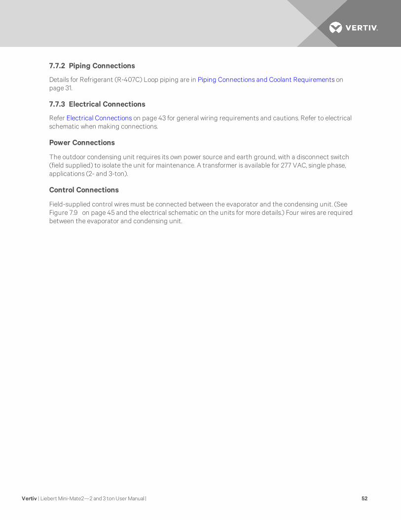
7.7.2 Piping Connections 52
7.7.3 Electrical Connections 52
7.8 Water and Glycol Cooled Condensing Unit 53
7.8.1 Location Considerations 53
7.8.2 Electrical Connections 55
7.8.3 Piping Connections 55
7.9 Optional Equipment Piping 56
7.9.1 Free-Cooling Coil 56
7.9.2 Hot Water Reheat Coil 57
7.10 Checklist for Completed Installation 59
8 Microprocessor Control 61
8.1 Feature Overview 61
8.2 Main Menu <Menu> 62
8.3 Setpoints 63
8.4 Status 63
8.5 Active Alarms 63
8.6 Time 64
8.7 Date 64
8.8 Setback 64
8.9 Setup Operation 64
8.9.1 Restart Time Delay 64
8.9.2 C/F Degrees 65
8.9.3 Humidity Control Method 65
8.10 Change Passwords 65
8.11 Calibrate Sensors 66
8.12 Alarm Enable 66
8.13 Alarm Time Delay 66
8.14 Common Alarm Enable 67
8.15 Custom Alarms 67
8.15.1 Standard Custom Alarm Messages 67
8.16 Custom Text 67
8.17 Run Diagnostics (Available On Rev 1.001.0 and Higher) 68
9 System Performance Microprocessor Controls 73
9.1 Temperature Control 73
9.1.1 Cooling/Heating Required 73
9.1.2 Cooling Operation (Cooling, Compressorized Direct Expansion and Chilled Water) 73
9.1.3 Heating Operation 73
Vertiv | Liebert Mini-Mate2—2 and 3 tonUser Manual | 4

9.2 Humidity Control 75
9.2.1 Dehumidification/Humidification Required 75
9.2.2 Dehumidification Operation, Compressorized Direct Expansion (DX) Systems 75
9.2.3 Humidification Operation 75
9.3 Load Control Features 75
9.3.1 Communication 75
10 Alarms 77
10.1 Standard Alarms: Definitions and Troubleshooting 77
10.1.1 Custom Alarms 77
10.1.2 High Head Pressure 78
10.1.3 Humidity Level 78
10.1.4 Temperature 79
10.1.5 Humidifier Problem Alarm 79
10.1.6 High Water Alarm 79
10.1.7 Loss of Power 79
10.1.8 Short Cycle 79
10.2 Optional/Custom Alarms 79
10.2.1 Change Filter 79
10.2.2 High Temperature Sensor—Optional 80
10.2.3 Smoke Detected 80
11 System Testing and Maintenance 81
11.1 System Testing 81
11.1.1 Environmental Control Functions 81
11.1.2 Cooling 81
11.1.3 Heating 81
11.1.4 Humidification 81
11.1.5 Dehumidification 81
11.1.6 High Temperature Sensor—Optional 81
11.1.7 Smoke Detector Sensor 81
11.1.8 Remote Shutdown 82
11.2 Maintenance 82
11.2.1 Electric Panel 82
11.2.2 Filters 82
11.2.3 Direct Drive Blower Package 82
11.2.4 High Static Belt Drive Blower Package (Option) 83
11.2.5 Refrigeration System 83
11.2.6 Humidifier Circuit Board Adjustments 87
11.3 Replacement Procedures 89
11.3.1 Compressor Replacement 89
11.3.2 Electrical Failure 89
11.3.3 Replacing the Humidifier Canister 90
12 Maintenance Inspection Checklist 93
Vertiv | Liebert Mini-Mate2—2 and 3 tonUser Manual | 5

13 Troubleshooting 95
Vertiv | Liebert Mini-Mate2—2 and 3 tonUser Manual | 6

1 IMPORTANT SAFETY INSTRUCTIONSSAVE THESE INSTRUCTIONS
This manual contains important safety instructions that should be followed during the installation andmaintenance of the Liebert Mini-Mate2. Read this manual thoroughly before attempting to install oroperate this unit. Only qualified personnel should move, install or service this equipment.
Adhere to all warnings, cautions and installation, operating and safety instructions on the unit and in thismanual. Follow all installation, operation and maintenance instructions and all applicable local andnational building, electrical and plumbing codes.
WARNING! Arc flash and electric shock hazard. Disconnect all electric power supplies and wearprotective equipment per NFPA 70E before working within electric control enclosure. Failure tocomply can cause serious injury or death. Customer must provide earth ground to unit, perNEC, CEC and local codes, as applicable. Before proceeding with installation, read allinstructions, verify that all the parts are included and check the nameplate to be sure thevoltage matches available utility power. The Liebert microprocessor control does not isolatepower from the unit, even in the Unit Off mode. Some internal components require and receivepower even during the Unit Off mode. The line side of the disconnect switch on the front of theunit contains live high-voltage. The only way to ensure that there is NO voltage inside the unitis to install and open a remote disconnect switch and check the internal power supply wireswith a voltmeter. Refer to unit electrical schematic. Follow all applicable local and nationalelectric codes.
WARNING! Risk of explosive discharge from high-pressure refrigerant. Can cause injury ordeath. This unit contains fluids and gases under high pressure. Relieve pressure beforeworking with piping.
WARNING! Risk of refrigerant system rupture or explosion from overpressurization. Can causeequipment damage, injury or death. If a pressure relief device is not provided with thecondenser unit, the system installer must provide and install a discharge pressure relief valveper local and national codes in the high side refrigerant circuit. Do not install a shutoff valvebetween the compressor and the field installed relief valve. Do not isolate any refrigerantcircuits from overpressurization protection.
WARNING! Risk of high-speed moving parts. Can cause injury or death. Open all local andremote electrical power disconnect switches before working in the unit and componentelectrical enclosures.
Vertiv | Liebert Mini-Mate2—2 and 3 tonUser Manual | 7

CAUTION: Risk of contact with hot surfaces. Can cause injury. The compressors, refrigerantdischarge lines, humidifiers and reheats are extremely hot during unit operation. Allowsufficient time for them to cool before working within the unit cabinet. Use extreme caution andwear protective gloves and arm protection when working on or near hot compressors,discharge lines, humidifiers and reheats.
CAUTION: Risk of leaking water. Can cause equipment and building damage. This unit requiresa water drain connection. It may also require an external water supply to operate. Improperinstallation, application and service practice can result in water leakage from the unit. Waterleakage can result in severe property damage and loss of critical data center equipment. Do notlocate unit directly above any equipment that could sustain water damage. Vertiv™recommends installing leak detection equipment for unit and supply lines and in the secondarydrain pan. Check drain lines periodically for leaks, sediment buildup, obstructions, kinks and/ordamage and verify that they are free running.
CAUTION: Risk of sharp edges, splinters and exposed fasteners. Can cause injury. Onlyproperly trained and qualified personnel wearing appropriate safety headgear, gloves, shoesand glasses should attempt to move the unit, lift it, remove packaging from or prepare the unitfor installation.
NOTICE
Risk of a leaking coil due to freezing and/or corrosion. Can cause equipment and seriousbuilding damage.
Cooling coils and piping systems that are connected to open cooling towers or other openwater/glycol systems are at high risk for freezing and premature corrosion. Fluids in thesesystems must contain the proper antifreeze and inhibitors to prevent freezing and prematurecoil corrosion. The water or water/glycol solution must be analyzed by a competent watertreatment specialist before startup to establish the inhibitor requirement. The water orwater/glycol solution must be analyzed every six months to determine the pattern of inhibitordepletion. The complexity of water-caused problems and their correction makes it important toobtain the advice of a water treatment specialist and follow a regularly scheduled maintenanceprogram.
NOTICE
Risk of damage from forklift. Can cause unit damage.
Keep tines of the forklift level and at a height suitable to fit below the skid and/or unit toprevent exterior and/or underside damage.
NOTICE
Risk of improper storage. Can cause unit damage.
Keep the Liebert Mini-Mate2 upright, indoors and protected from dampness, freezingtemperatures and contact damage.
Vertiv | Liebert Mini-Mate2—2 and 3 tonUser Manual | 8

2 PRODUCT NUMBER NOMENCLATUREFigure 2.1 Model number nomenclature—Evaporator units
Figure 2.2 Model number nomenclature—Air-cooled, indoor condensing units
Vertiv | Liebert Mini-Mate2—2 and 3 tonUser Manual | 9

Figure 2.3 Model number nomenclature—Outdoor air-cooled prop fan condensing units
Figure 2.4 Model number nomenclature—Water/glycol-cooled condensing units
Vertiv | Liebert Mini-Mate2—2 and 3 tonUser Manual | 10

Figure 2.5 Model number nomenclature—Chilled water units
Vertiv | Liebert Mini-Mate2—2 and 3 tonUser Manual | 11

Vertiv | Liebert Mini-Mate2—2 and 3 tonUser Manual | 12
This page intentionally left blank.

3 INTRODUCTION3.1 Designed to Match Computer and Electronic Equipment Needs—FromInstallation to Operation
Installed above the ceiling, Liebert Mini-Mate2 Precision Cooling systems control the cooling, humidityand air distribution required by sensitive electronic equipment. A range of sizes and configurations isavailable to meet varying sites’ needs.The Liebert Mini-Mate2 is also easy to use. Advanced microprocessor technology allows easy, precisecontrol, and menu-driven monitoring keeps you informed of system operation through the LCD readout.These features, combined with Vertiv™ quality construction and reliable components, guaranteesatisfaction from installation through operation.
Liebert Precision Cooling
Liebert Precision Cooling systems are designed to control the environment required for computers andother sensitive electronic equipment. The Liebert Mini-Mate2 provides complete control on an around-the-clock basis and the high sensible heat ratio required by sensitive electronic equipment.
Easy Installation
The Liebert Mini-Mate2 is a split-system evaporator combined with an air-, water- or glycol-cooledcondensing unit or is a self-contained, chilled water unit. Each split system has thermostat-type wiring tocontrols and condensing unit. System components are pre-charged with refrigerant and can beconnected together with optional pre-charged line sets or optional sweat adapters for field refrigerantpiping.
Easy to Service
Low-maintenance components are easily accessed through removable front panels. Spare parts arealways in Vertiv™ inventory and available on short notice.
Advanced Control Technology
A menu-driven microprocessor control system provides precise temperature and humidity control andaccurate alarm setpoints. Using touch-sensitive buttons, the wall-mounted monitor/control panel allowsyou to select and display temperature and other monitored parameters.
High Efficiency
High sensible heat ratio, scroll compressor and precise microprocessor control allow the system to operateefficiently.
Space Saving Design
All indoor components are installed above the ceiling, so no floor space is required.
Reliable
The Liebert Mini-Mate2 family installed base is a testimony to the system reliability. Components include arugged scroll compressor, high-efficiency copper tube, aluminum-fin evaporator coil and a double inlet,direct drive fan.
Vertiv | Liebert Mini-Mate2—2 and 3 tonUser Manual | 13

Agency Listed
Standard 60Hz units are CSA certified to the harmonized U.S. and Canadianproduct safety standard, CSA C22.2 No 236/UL 1995 for “Heating and CoolingEquipment” and are marked with the CSA c-us logo.
Location
When considering installation locations, consider that these units containwater and that water leaks can cause damage to sensitive equipment below. Donot mount these units above sensitive equipment. A field-supplied pan withdrain must be supplied beneath cooling units and water/glycol condensers.Do not mount units in areas where normal unit operating sound might disturb the working environment.
Vertiv | Liebert Mini-Mate2—2 and 3 tonUser Manual | 14

4 STANDARD FEATURES—2 & 3 TON SYSTEMS
4.1 Evaporator Section - Split Systems
The evaporator section is designed for ceiling installation. The cabinet and chassis are constructed ofheavy gauge galvanized steel. The unit can be serviced using only one side increasing its versatility inmounting locations. Mounting brackets are factory-attached to the cabinet. Internal cabinet insulationmeets ASHRAE 62.1 requirements for Mold Growth, Humidity & Erosion, tested per UL 181 and ASTM 1338standards.
The evaporator section includes the evaporator coil, R-407C unit charge, filter-drier, factory-mounteddisconnect switch, two-speed direct-drive blower assembly and microprocessor control with wall-mountedcontrol box. The unit is provided with supply and return air openings for field-supplied ducting orsupply/return plenum. Evaporators can be configured with canister humidifier and/or reheat. An indoor oroutdoor condensing unit must be selected for each evaporator.
4.2 Condensing Unit Section—Split Systems
4.2.1 Indoor Centrifugal Fan Condensing Units
Indoor Air-Cooled Centrifugal Fan Condensing Units include scroll compressor, factory-mounteddisconnect switch, condenser coil, R-407C unit charge, belt-driven centrifugal blower assembly,high-pressure switch, Liebert Lee-Temp™ head pressure control system, hot gas bypass and liquid-linesolenoid valve. Unit must be mounted indoors. Condensing unit is designed to use outdoor air withtemperatures ranging from -30°F to 95°F (-34°C to 35°C).
4.2.2 Outdoor Prop Fan Condensing Units
Outdoor Prop Fan Condensing Units include scroll compressor, condenser coil, R-407C unit charge, propfan, liquid-line solenoid valve, high pressure switch, Liebert Lee-Temp head pressure control and hot gasbypass. Condensing unit is designed for outdoor locations with operating ambients ranging from -30°F to95°F (-34°C to 35°C).
4.2.3 Indoor Water/Glycol Condensing Units
Indoor Water/Glycol Condensing Units includes scroll compressor, R-407C unit charge, factory-mounteddisconnect, coaxial condenser, hot gas bypass, high head pressure switch and two-way water regulatingvalve designed for 150psi (1034.3kPa). Condensing units can be used on either a water or glycol coolingloop.
4.3 Chilled Water Units
Chilled Water Units are designed for ceiling installation. The cabinet and chassis are constructed of heavygauge galvanized steel. The unit can be serviced using only one side increasing its versatility in mountinglocations. Mounting brackets are factory-attached to the cabinet. Internal cabinet insulation meetsASHRAE 62.1 requirements for Mold Growth, Humidity & Erosion, tested per UL 181 and ASTM 1338standards. Chilled water models are self-contained and include a chilled water coil, two-speed, direct-drivecentrifugal blower, factory-mounted disconnect switch and two-way, slow-close motorized valve. Designpressure is 300psi (2068kPa), 60psi (414kPa) close-off differential.
Vertiv | Liebert Mini-Mate2—2 and 3 tonUser Manual | 15

4.4 System Controls
System controls include a microprocessor control board mounted in the evaporator/chilled water unit anda wall-mounted interface with a two-line, 16-character liquid crystal display. An eight-key, membranekeypad for setpoint/program control, unit On/Off, fan speed and alarm silence is below the LCD screen. Itprovides temperature setpoint and sensitivity adjustment, humidity setpoint and sensitivity adjustment,digital display of temperature, humidity, setpoints, sensitivities, fan speed and alarm conditions.
The wall-box is field-wired to the microprocessor control using standard four-conductor thermostat wire(field-supplied). The temperature and humidity sensors are in the wall box, which can be installed up to300 feet (91.4m) from the evaporator unit. The unit-mounted control board also includes common alarmterminals and shutdown terminals. The unit automatically restarts after a power outage.
Figure 4.1 Wall-box
4.4.1 Other Standard Control Features
• Adjustable auto restart
• 5 day/2 day setback
• Password protection
• Alarm enable/disable
• Self-diagnostics
• Calibrate sensors
• Predictive humidity control
• Common alarm output
• Remote shutdown terminals
Vertiv | Liebert Mini-Mate2—2 and 3 tonUser Manual | 16

5 OPTIONAL FACTORY-INSTALLED FEATURES—EVAPORATOR/CHILLED WATER UNITS
5.1 Reheat
Electric Reheat includes 304/304 stainless steel finned tubular reheat elements, with high limit safetyswitch.
SCR Electric Reheat uses an SCR controller and unit control software to provide full cooling withmodulating of the electric reheat elements to control air temperatures. Reheat capacity is up-sized tooffset the cooling capacity. (The SCR Electric Reheat is not available on chilled water, free-cooling or 575Vunits.)
Hot Water Reheat includes hot water coil, 2-way solenoid valve and Y-strainer.
NOTE: This option is available only on Chilled Water units, but not with other reheat options.
5.2 Humidifier
The Canister Humidifier includes a steam-generating type humidifier with automatic flushing circuit, inletstrainer, drain, 1" (25.4mm) air gap on fill line and solenoid valves. Humidifier problem alarm annunciates atthe wall-mounted display panel.
Remote Humidifier Contact allows the unit’s humidity controller to control a humidifier outside the unit.Power to operate the remote humidifier does not come from the Liebert Mini-Mate2. Available on unitswith or without internal humidifier.
5.3 Sensors
Smoke Sensor checks return air, shuts down the unit upon sensing smoke and activates visual andaudible alarms at the wall-box display. This smoke sensor is not intended to function as or replace anysmoke sensor system that may be required by local or national codes.
High-Temperature Sensor senses the return air temperature and shuts down unit if the temperaturereaches 125°F (52°C). This device is not meant to replace any fire detection system that may be requiredby local or national codes.
5.4 Switches and Motors
Filter Clog senses pressure drop across the filters and activates visual and audible alarms at the wall-boxdisplay. The wall-box display annunciates the alarm and flashes a notification upon reaching a customersetpoint.
A Factory-Installed Non-Fused Disconnect Switch allows unit to be turned off for maintenance. Adisconnect switch is standard for the evaporators, chilled water units and indoor condensing units, butthese units may be specified without the switch.
Direct-Drive blower can be factory-eliminated from the evaporator/chilled water cabinet for high staticapplications (0.9 to 1.5in. [23 to 38mm] w.g.). See Ship-Loose Accessories—Field-Installed on page 21 forthe optional, externally mounted high static blower assembly.
Vertiv | Liebert Mini-Mate2—2 and 3 tonUser Manual | 17

5.5 Free-Cooling
Free-cooling option includes separate cooling coil, three-way slow-close valve and separate supply andreturn piping. Free-cooling is activated when the water temperature reaches a field-adjustabletemperature, typically 45°F (7°C). The valve is rated for 300psi (2068kPa) working pressure.Air-cooled condensing units can be matched with evaporators using free-cooling coils with chilled watersources to serve as backup cooling. When matched with a water/glycol condensing unit, a three-waywater regulating valve is recommended for the condensing unit to simplify piping to the main supplypipes. The coil is designed for closed-loop applications using properly treated and circulated fluid. Notavailable with SCR reheat options.
Figure 5.1 Free-cooling arrangement
NOTE: If free-cooling is applied to an open water tower, an optional copper-nickel (CuNi) coil isrequired to prevent premature corrosion, or a heat exchanger must separate the tower water from thefree-cooling loop. The copper-nickel coil requires an extended lead time.
5.6 Optional Configurations—Prop Fan Condensing Units
Outdoor Prop Fan Condensing Units are also available in the following optional configurations:
• High ambient models for providing catalog capacities at ambient temperatures up to 105°F(40°C).
• Quiet-Line models for low noise level conditions (below 56 dBA) and for providing catalogcapacities at ambient temperatures up to 95°F (35°C).
• Condenser coils can be phenolic-coated for extended coil life in coastal areas.
5.7 Optional Configurations—Water/Glycol Condensing Units
Indoor Water/Glycol Condensing Units are also available with the following piping options:
• Two-way water reg. valve with 350 psi (2413kPa) design pressure.
• Three-way water reg. valve with 150psi (1034kPa) design pressure.
• Three-way water reg. valve with 350psi (2413kPa) design pressure.
Vertiv | Liebert Mini-Mate2—2 and 3 tonUser Manual | 18

5.8 Optional Configurations—Chilled Water Units
Chilled Water Units are also available with the following valve option:
• Three-way, slow-close, motorized chilled water valve rated for 300 psi (2068 kPa) workingpressure. Valve is non-spring return.
Vertiv | Liebert Mini-Mate2—2 and 3 tonUser Manual | 19

Vertiv | Liebert Mini-Mate2—2 and 3 tonUser Manual | 20
This page intentionally left blank.

6 SHIP-LOOSE ACCESSORIES—FIELD-INSTALLEDA High Static Blower Assembly can be field-attached to the evaporator to provide up to 2.0" (51mm) ofexternal static pressure on the discharge side of the evaporator. The blower box contains a centrifugal-type double-inlet blower. This blower is equipped with a belt drive and 1.5 hp single speed motor mountedto an adjustable motor base. Note: Unit must be ordered without the internal direct drive motor and thehigh static blower disables the two-speed fan operation feature.
Filter box kit (for ducted applications) includes filter box with duct flange connection, one MERV 8(ASHRAE 52.2-2007) filter (20"x20"x4" [508mm x 508mm x 102mm]), and a duct flange for use on thesupply air opening of the unit
Air Distribution Plenum includes molded plastic three-way discharge plenum, 16"x25"x4" (406mm x535mm x 102mm) MERV 8 filter (ASHRAE 52.2-2007), and sheet metal block-off plates for covering theduct openings on the evaporator unit. Plenum mounting requires T-bar ceiling grid.
The Condensate Pump is field-mounted external to the cabinet, wired to the unit power block and isequipped with a check valve. A secondary float can be field-wired to shut down the unit upon highcondensate level.
A Remote Temperature and Humidity Sensor package includes sensors in an attractive case with 30 ft. (9m) of cable. Can be wall or duct mounted. Remote sensors should be used when the wall box is not locatedin the space to be conditioned.
NOTE: Installing the remote sensors disables the sensors included in the wall box.
Field-Installed Kits available for filter clog, smoke sensor, high-temperature sensor, electric reheat andhumidifier. The kits include installation instructions and are designed to be added to the evaporator unitbefore it is installed in the ceiling. Electric reheat kits cannot be installed in units with free-cooling.
277-to-208V step-down transformer (37.5 amps) allows use of 277-1-60 supply power with a 208-1-60 PropFan Condensing unit. The transformer is coated with epoxy and contained in an enclosed, non-ventilatedelectrical box with adaptable mounting brackets.
Single-Point Power Kit contains the necessary electrical components to interconnect the high-voltagesections of a close-coupled evaporator and an MCD condensing unit.
Pre-Charged Refrigerant Line Set (R-407C) contains an insulated copper suction line and a copper liquidline for interconnection of the indoor and outdoor sections. Available in 15-foot (4.5m) and 30-foot (9m)sections.
The Refrigerant-Line Sweat Adapter Kit contains two suction and two liquid line fittings that allow field-supplied refrigerant piping between the evaporator and condensing unit.
Vertiv | Liebert Mini-Mate2—2 and 3 tonUser Manual | 21

6.1 Remote Monitoring, Autochangeover and Leak Detection Equipment
The Liebert RCM4™ is a four-point, normally open, dry contact monitoring panel. One Form-C, dry contactcommon alarm relay output (rated at 24 VAC, 3 Amp) is provided. Four red LEDs illuminate on therespective alarm and the alarm buzzer is silenced by a front panel switch. The RCM4 requires a 24VAC or24VDC power source. Power supply is not included.
The Liebert AC4™ Autochangeover Controller provides autochangeover and autosequence control for upto four Liebert Mini-Mate2 units within a room. The Liebert AC4 will enable redundant units in an alarmcondition, balance usage and test standby units at programmed intervals. Two common alarm relayoutputs are available. A built-in LCD and RS-232 port for direct PC/terminal connection provides twooptions for configuration and monitoring of the product. The Liebert AC4 requires 24VAC input power.
The Liebert AC8™ is ideal for coordinated control of systems with redundant units. The Liebert AC8enables redundant devices during an alarm condition, balances usage of devices and tests standbydevices at programmable intervals. Supports four zones and can use the 4-20mA temperature sensor(TW420) for temperature staging in each zone. Two programmable output control relays are available forauxiliary control such as humidity lockout. Emergency power operation input provided for device controlduring an emergency. Two common alarm relay outputs are available. A built-in LCD and RS-232 port fordirect PC/terminal connection provides two options for configuration and monitoring of the product.
The Liebert ENV-DO™ interface card provides 16 discrete outputs, corresponding to status and majoralarm conditions of Environmental units. The Liebert ENV-DO-ENCL1 packages one Environmental DOinterface card in its own steel enclosure and the ENV-DO-ENCL2 packages two Environmental DOinterface cards in one enclosure for installation external to the Liebert Mini-Mate2. The self-contained kitincludes an external 120VAC-to-24VAC power transformer. Wiring harnesses are not provided. Power andcommunication wiring is field-provided.
The Liebert Liqui-tect® 410 Point Leak Detection Sensor detects the presence of conductive liquid usinga pair of corrosion-resistant, gold-plated probes mounted in a painted, height-adjustable enclosure. DualForm-C, dry contact common alarm relays (rated at 24VAC, 3A) signal a leak detected as well as loss ofpower and cable fault. The Liebert Liqui-tect 410 requires an external 24VAC or 24VDC power source.
Liebert LT460 Zone Leak Detection Kits include one LT460 sensor, a specified length of LT500-xxYcable (maximum length is 100 ft [30.5m]) and a corresponding number of hold-down clips. The LiebertLT460 requires an external 24VAC, 0.12A power source, such as EXT-XFMR or XFMR24.
Liebert SiteScan® is a monitoring solution that gives you decision-making power to effectively manage theequipment critical to your business.
Liebert SiteScan enables communication from Liebert environmental and power units, as well as manyother pieces of analog or digital equipment, to a front-end software package that provides real-timestatus and alarms so you can react quickly to changing situations.
Vertiv | Liebert Mini-Mate2—2 and 3 tonUser Manual | 22

Liebert SiteScan is designed with flexibility for both small systems and large, complex systems such asthose in computer rooms, telecommunications facilities or industrial process control rooms. Contact yourlocal Vertiv™ representative for assistance with a Liebert SiteScan system.
The NIC-ENCL1 and NIC-ENCL2 package one or two Liebert IntelliSlot® Web/485 Cards with Adapters,respectively, in one steel enclosure for installation external to the Liebert Mini-Mate2. The LiebertIntelliSlot Web/485 Card with Adapter provides communication with the Liebert Mini-Mate2™ via SNMP,HTTP, RTU Modbus 485 and BACnet IP. The self-contained kit includes an external 120VAC-to-24VACtransformer as a power source. Wiring harnesses are not provided. Power and communication wiring arefield-provided.
Vertiv | Liebert Mini-Mate2—2 and 3 tonUser Manual | 23

Vertiv | Liebert Mini-Mate2—2 and 3 tonUser Manual | 24
This page intentionally left blank.

7 SITE PREPARATION AND INSTALLATIONNOTE: Before installing unit, determine whether any building alterations are required to run piping,wiring and ductwork. Carefully follow all unit dimensional drawings and refer to the submittalengineering dimensional drawings of individual units for proper clearances.
7.1 Installation Considerations
The evaporator unit is usually mounted above the suspended ceiling of the space to be conditioned.Ducted systems may be installed in a different room.
7.1.1 System Configurations
The typical system configuration has a separate evaporator or cooling unit and a condensing unit. Chilledwater systems are self-contained units. Refer to Table 7.1 below and Table 7.2 below and to Figure 7.1 onpage 27, Figure 7.2 on page 28 and Figure 7.3 on page 28 for different system combinations and unitconfigurations that are possible.
NominalCapacity
CoolingUnit
Condensing Unit
Indoor Air-Cooled Centrifugal fan Outdoor Air-Cooled Propeller Fan Indoor Water/Glycol
2 Tons MM_24E MC_24A PFH_27A MC_26W
3 TonsMM_36E MC_36A PFH_37A MC_38W
MM_40C Self-Contained - Chilled Water
Table 7.1 System configurations - 60Hz
NominalCapacity
CoolingUnit
Condensing Unit
Indoor Air-Cooled Centrifugal fan Outdoor Air-Cooled Propeller Fan Indoor Remote Water/Glycol-Cooled
3 TonsMM_35E MC_35A PFH_36A MC_37W
MM_39C Self-Contained - Chilled Water
Table 7.2 System configurations - 50Hz
Input Voltage Range ofReturnAir Conditions to Unit
Minimum Maximum Dry Bulb Temperature Relative Humidity
-5% +10% 65°F to 85°F (18°C to 29°C) 20% to 80%
*Unit will operate at these conditions but will not control to these extremes of conditions.
Table 7.3 Application limits, evaporator and chilled water units*
Vertiv | Liebert Mini-Mate2—2 and 3 tonUser Manual | 25

Input Voltage
Condensing Units
Entering Dry Bulb Air Temperature
Minimum Maximum Minimum Maximum
-5% +10%
Outdoor Prop Fan
Condensing Unit-30°F (-34°C)
115°F (46°C) standard unit*
125°F (52°C) high ambient unit*
Indoor Air-Cooled
Condensing Unit115°F (46°C)*
*Unit capacity ratings are stated for 95°F (35°C) for standard units and 105°F (41°C) for high ambient PFH units only.
Exceeding these rating points by 20°F (11°C) will result in lower cooling capacities, but will not damage the equipment.
Table 7.4 Application limits, indoor and outdoor air-cooled condensing units
Input Voltage Entering Fluid Temperature
Minimum Maximum Minimum Maximum
-5% 65°F (18.3°C) *
*Operation below 65°F (18°C) may result in reduced valve life and fluid noise.
Table 7.5 Application limits, indoor water/glycol-cooled condensing units
7.1.2 Room Preparation
The room should be well insulated and must have a sealed vapor barrier. The vapor barrier in the ceilingand walls can be a polyethylene film. Paint on concrete walls and floors should contain either rubber orplastic.
NOTE: The single most important requirement for maintaining environmental control in theconditioned room is the vapor barrier.
Outside or fresh air should be kept to a minimum when tight temperature and humidity control isrequired. Outside air adds to the cooling, heating, dehumidifying and humidifying loads of the site. Doorsshould be properly sealed to minimize leaks and should not contain ventilation grilles.
Vertiv | Liebert Mini-Mate2—2 and 3 tonUser Manual | 26

7.1.3 Location Considerations
CAUTION: Risk of leaking water/glycol. Can cause building and equipment damage. Do notmount units over equipment and furniture that can be damaged by leaking water/glycol. Installa watertight drain pan with a drain connection under the cooling unit and water/glycolcondenser unit. Route the drain to a frequently used maintenance sink so that running watercan be observed and reported in a timelymanner. Post a sign to alert people to report waterflowing from the secondary drain pan.
NOTE: Do not mount units in areas where normal unit operating sound may disturb the workingenvironment.
Install the evaporator unit over an unobstructed floor space if possible. This will allow easy access forroutine maintenance or service. Do not attach additional devices (such as smoke detectors, etc.) to thehousing, as they could interfere with the maintenance or service.
NOTE: Temperature and humidity sensors are in the wall box. Install the wall box where discharge airDOES NOT blow directly on the sensors.
When using the optional air distribution plenum, avoid locating the evaporator unit in confined areas thataffect the air flow pattern. Such locations could cause short cycles, downdrafts and air noise. Avoidlocating the unit in an alcove or at the extreme end of a long, narrow room. Avoid installing multiple unitsclose to each other. This could result in crossing air patterns, uneven loads and competing operatingmodes.
When installing an air-cooled or water/glycol-cooled unit inside a space, ensure that national and localcodes are met for refrigerant concentration limits that might vary with building type and use.
Figure 7.1 Air-cooled systems, 2 and 3 tons
Vertiv | Liebert Mini-Mate2—2 and 3 tonUser Manual | 27

Figure 7.2 Water/glycol-cooled systems, 2 and 3 tons
Figure 7.3 Chilled water systems, 3 tons
7.2 Ceiling Unit Weights
Model# Weight lb (kg)
Cooling Units *
MMD24E 225 (102)
MMD35E 225 (102)
MMD36E 225 (102)
MMD39C 230 (104)
MMD40C 230 (104)
Indoor Condensing Units
MCD24A 270 (125)
MCD35A 280 (130)
Table 7.6 Ceiling unit weights
Vertiv | Liebert Mini-Mate2—2 and 3 tonUser Manual | 28

Model# Weight lb (kg)
MCD36A 280 (130)
MCD26W 190 (90)
MCD37W 200 (95)
MCD38W 200 (95)
MCD38W 200 (95)
*Add 20 lb. (9kg) to units with free-cooling or hot water reheat coils.
Table 7.6 Ceiling unit weights (continued)
7.3 Equipment Inspection—Upon Receipt
When the unit arrives, do not uncrate equipment until it is close to its final location. All requiredassemblies are banded and shipped in corrugated containers. If you discover any damage when youuncrate the unit, report it to the shipper immediately. If you later find any concealed damaged, report it tothe shipper and to your Liebert supplier.
7.4 Packaging Material
All material used to package this unit is recyclable. Save it for future use or dispose of the materialappropriately.
7.5 Installing the Ceiling Units
WARNING! Risk of ceiling collapse and heavy unit falling. Can cause building and equipmentdamage, serious injury or death. Verify that the supporting roof structure is capable ofsupporting the weight of the unit(s) and the accessories. (see Ceiling Unit Weights on theprevious page.) Be sure to securely anchor the top ends of the suspension rods. Make sure allnuts are tight.
The evaporator unit and condensing unit are usually mounted above the ceiling and must be securelymounted to the roof structure. The ceiling and ceiling supports of existing buildings may requirereinforcements. Be sure to follow all applicable national and local codes. Use field-supplied threadedsuspension rods and 3/8-16 factory hardware kit.
Recommended clearance between ceiling grids and building structural members is unit height plus 3 in(76mm).
Install the four field-supplied rods by suspending them from suitable building structural members. Locatethe rods so that they will align with the four mounting holes in the flanges that are part of the unit base.
Using a suitable lifting device that is rated for the weight of the unit (see Ceiling Unit Weights on theprevious page), raise the unit and pass the threaded rods through the four mounting holes in the flangesthat are part of the unit base.
Vertiv | Liebert Mini-Mate2—2 and 3 tonUser Manual | 29

Attach the threaded rods to the unit flanges using the supplied nuts and grommets. (See Figure 7.4below). The rubber grommets provide vibration isolation.
1. First, use the plain nuts to hold unit in place. Adjust these nuts so that the weight of the unit issupported evenly by the four rods, does not rest on the ceiling grid, and to ensure the unit islevel.
NOTE: The units must be level in order to drain condensate properly.
2. Second, use the shake-proof nuts to “jam” the plain nuts.
Figure 7.4 Threaded rod and hardware kit installation
7.5.1 Close-Coupled Installations
If the evaporator and indoor condensing units are to be mounted back-to-back (close-coupled), hangeach unit before connecting them together. Align four bolt holes in the condensing unit with cage nuts inthe evaporator. Insert rubber spacers and secure with provided hardware. Align the refrigerantconnections and tighten them as described in Piping Connections and Coolant Requirements on thefacing page (see Figure 7.10 on page 46).
Close-coupled installations may take advantage of a single-point power kit to allow one power feed toprovide input for both evaporator and condensing units. Kit should be mounted in evaporator unit beforeraising unit into ceiling area.
Vertiv | Liebert Mini-Mate2—2 and 3 tonUser Manual | 30

7.5.2 Evaporator Air Distribution
Filter Box
The optional filter box is available for the unit and mounts directly to the return air opening of theevaporator. The 2 and 3 ton filter box is supplied with a MERV 8 filter (per ASHRAE 52.2-2007) measuring20 in. x 20 in. x 4 in. (508x508x102mm).
Plenum Installation
The 2- and 3-ton non-ducted evaporators can use the optional ceiling-mounted plenum to provide four-way air distribution. The plenum fastens to the bottom of the evaporator. The plenum includes a 16 in. x 25in x 4 in (406x635x102mm) MERV 8 filter (per ASHRAE 52.2-2007).
1. The evaporator should be mounted above the bottom of the T-bar supports with at least 30 in.(762mm) clearance from return air end to wall (for replacing filter).
2. Check the contents of the plenum kit.
3. Follow the installation instructions included with the plenum kit.
NOTE: Do not operate the unit without filters installed in the return air system.
Connections for Ducted Systems
In a ducted configuration, the direct drive evaporator has a maximum allowable external static pressure of0.3" wg (7.6 mm). Use flexible ductwork or non-flammable cloth collars to attach ductwork to the unit andto help control the transmission of vibrations to building structures. Insulation of ductwork is vital toprevent condensation during the cooling cycle. The use of a vapor barrier is required to preventabsorption of moisture from the surrounding air into the insulation.
If the return air duct is short, or if noise is likely to be a problem, sound-absorbing insulation should beused inside the duct. Ductwork should be fabricated and installed in accordance with local and nationalcodes.
FanSpeed2 TonCFM (CMH)
3 TonCFM (CMH)
High 885 (1504) 1250 (2124)
Low 800 (1359) 1000 (1699)
Table 7.7 Cooling unit air flow at0.3 IWG (75PA) ESP
7.5.3 Piping Connections and Coolant Requirements
The following pipe connections are required:
• A drain line from the evaporator coil drain pan (This line also serves as the drain for theoptional humidifier.)
• A drain line from the secondary drain pan beneath the unit.
• A water supply line to the optional humidifier (if applicable).
• Refrigerant piping connections between the evaporator unit and the condensing unit (air,water, or glycol). If the evaporator unit is chilled water, connections to the building chilled watersource are required.
Vertiv | Liebert Mini-Mate2—2 and 3 tonUser Manual | 31

Drain Line
NOTICE
Risk of water backing up in the evaporator coil drain line. Can cause building and equipmentdamage from overflowing water.
Do not install an external trap in the drain line. This line already has a factory-installed trapinside the cabinet.
This line may contain boiling water. Use copper or other suitable material for the drain line.
A 3/4 in. (19.1 mm) NPT female connection is provided for the evaporator coil condensate drain. This linealso drains the humidifier, if applicable. The drain line must be located so it will not be exposed to freezingtemperatures. The drain should be the full size of the drain connection.
The evaporator drain pan includes a float switch to prevent operation if drain becomes blocked.
The optional condensate pump kit is required when the evaporator is installed below the level of thegravity-fed drain line.
NOTE: Remove any shipping band from the float switch in the evaporator pan before operating unit.
Humidifier Water Supply Line
Units supplied with the optional humidifier package have a 1/4 in. (6.4 mm) compression fitting withferrule at the water supply connection Supply pressure range is 10 PSIG to 150 PSIG. Required flow rate is1 gpm. A shut-off valve should be installed in this line to isolate the humidifier for maintenance.
Assembly Instructions
1. Cut tube square and remove cutoff burr.
2. Slide nut then sleeve on tube, threaded end on nut facing end of tube.
3. Insert tube into fitting seating it against stop shoulder and thread nut to body “hand-tight.”
4. With proper wrench tighten 1-1/4 to 2-1/4 turns.
NOTICE
Risk of improper tightening of the piping fittings. Can cause fitting damage and leaks that canresult in building and equipment damage.
Do not over tighten the piping fittings
Chilled Water Loop
On chilled water units, install manual service shutoff valves at the supply and return lines of each unit.These shutoff valves are used for routine service or emergency isolation of the unit.
Chilled water supply and return lines must be insulated. Insulating them will prevent condensation of thewater supply and return lines to the unit.
The minimum recommended water temperature is 42¡F. Design pressure is 300psig (2068 kPag).Connection sizes are 7/8 in (22.2mm) OD copper for 3 ton units.
Vertiv | Liebert Mini-Mate2—2 and 3 tonUser Manual | 32

Water/Glycol Loop
Vertiv™ recommends installing manual service shutoff valves at the supply and return line to each unit.This permits routine service and emergency isolation of the unit. Install 1/2" (13mm) diameter condensingfluid inlet and 1/2" (13mm) diameter condensing fluid outlet.
When the condensing fluid quality is poor, Vertiv™ recommends placing proper filters in the supply line toextend the service life of the condenser. These filters must be easily replaced or cleaned. The standardmaximum fluid pressure is 150 psig (1034 kPa) or optional 350 psig (2413 kPa) systems. For applicationsabove this pressure, consult the factory.
The water/glycol-cooled system will operate in conjunction with a cooling tower, city water or drycooler.
NOTICE
Risk of frozen pipes and corrosion from improper coolant mixture. Can cause equipment andbuilding damage.
When piping or the Liebert Mini-Mate2 may be exposed to freezing temperatures, charge thesystem with the proper percentage of glycol and water for the coldest design ambient.Automotive antifreeze is unacceptable and must NOT be used in any glycol fluid system. Useonly an HVAC glycol solution only that has been prepared according to industry practices.
Refrigerant (R-407C) Loop
All split systems require two refrigerant lines (an insulated copper suction line and a copper liquid line)between the evaporator and the condensing unit.
The refrigerant lines can be piped by installing:
• an optional sweat adapter kit and hard piping between the two units
• optional pre-charged line sets (maximum combined length of 45' [13.7m])
• close coupling the units together using the quick connects. (See Figure 7.10 on page 46)
WARNING! Risk of explosive discharge from high-pressure refrigerant. Can cause injury ordeath. This unit contains fluids and gases under high pressure. Relieve pressure beforeworking with piping.
All refrigeration piping should be installed with high-temperature brazed joints. Prevailing goodrefrigeration practices should be employed for piping supports, leak testing, evacuation, dehydration andcharging of the refrigeration circuits. The refrigeration piping should be isolated from the building withvibration-isolating supports. To prevent tube damage when sealing openings in walls and to reducevibration transmission, use a soft, flexible material to pack around the tubes.
NOTICE
Risk of twisted or kinked piping. Can cause flow restriction or leaks.
Handle the pre-charged lines with care so they do not get kinked or damaged. Use tubebenders and make all bends before making connections to either end. Coil any excess tubingin a horizontal plane with the slope of the tubing toward the condensing unit.
Vertiv | Liebert Mini-Mate2—2 and 3 tonUser Manual | 33

Field-Fabricated Piping
All field-fabricated refrigeration piping should use copper pipe with high-temperature brazed joints. Abrazing alloy with a minimum temperature of 1350°F (732°C), such as Sil-Fos. Avoid soft solders such as50/50 or 95/5.
1. Use sweat adapter kit matched to the Liebert Mini-Mate2 and outdoor condensing unitrefrigerant connection sizes.
2. Measure pipe runs and calculate pipe size and equivalent feet of suction and liquid lines perTable 7.8 on the facing page and Table 7.12 on page 37.
3. Use a flow of dry nitrogen through the piping during brazing to prevent formation of copperoxide scale inside the piping. Copper oxide forms when copper is heated in the presence of air.POE oil will dissolve these oxides from inside the copper pipes and deposit them throughoutthe system, clogging filter driers and affecting other system components. A pure dry nitrogenflow of 1-3 ft3/min (0.5-1.5 l/s) inside the pipe during brazing is sufficient to displace the air.Control the flow using a suitable metering device.
4. Pressurize and leak-test the completed lines at approximately 150 psig (1034kPa) pressure.
5. Evacuate each line twice to 500 microns. Break the vacuum each time with clean, dry nitrogen.
6. Evacuate the lines a third time to 500 microns.
7. See Quick Connect Fittings on page 38 for the proper procedure to connect lines to each unitof the split system.
8. Add refrigerant (R-407C) to the completed system as calculated per Table 7.10 on page 36 forboth liquid and suction line sizes used.
When installing remote condensing units above the evaporator, the suction gas line should be trapped atthe evaporator. This trap will retain refrigerant oil during the Off cycle. When the unit starts, oil in the trapis carried up the vertical riser and returns to the compressor (see Figure 7.5 on the facing page).
Vertiv | Liebert Mini-Mate2—2 and 3 tonUser Manual | 34

Figure 7.5 Refrigerant piping diagram
NOTE: When installing remote condensing units below the evaporator, the suction gas line should betrapped with an inverted trap the height of the evaporator. This prevents refrigerant migration to thecompressor during off cycles.
EquivalentLength, ft (m)
2 Ton 3 Ton
Suction Liquid Suction Liquid
50 (15.2) 7/8" 3/8" 7/8" 1/2"
100 (30.5) 7/8" 1/2" 1-1/8"2 1/2"
150 (45.7) 7/8" 1/2" 1-1/8"2 1/2"
1. Suction line and liquid line sizing based on < 3 psi pressure drop in each and horizontal suction line refrigerant velocities>700FPM (3.6m/s).
2. Suction size should be reduced one pipe size for vertical riser sections to maintain suction line velocity > 1000FPM (5.1m/s) forproper oil return.
Table 7.8 Recommended refrigerant line sizes
Vertiv | Liebert Mini-Mate2—2 and 3 tonUser Manual | 35

Nominal System Size Tons Max. Equiv. Pipe Length ft. (m)Maximum PFH LevelAboveEvaporator, ft. (m)
Maximum PFH Level BelowEvaporator, ft. (m)
2 150 (45) 40 (12) 15 (4.6)
3 150 (45) 50 (15) 15 (4.6)
Maximum recommended total equivalent pipe length is 150 ft (46m). Suction and liquid lines may require additional specialty items when vertical linesexceed 20 ft. (6m) and/or condensing unit installation is more than 15 ft. (4.6m) below the evaporator. Contact Vertiv™ Application Engineering forassistance.
Table 7.9 Pipe length and condenser elevation relative to evaporator
Line Size, O.D., in.
R-407C, lb/100 ft. (kg/30m)
Liquid Line Suction Line
3/8 3.7 (1.7) —
1/2 6.9 (3.1) —
5/8 11.0 (5.0 0.4 (0.2)
3/4 15.7 (7.1) 0.6 (0.3)
7/8 23.0 (10.4) 1.0 (0.4)
1-1/8 — 1.7 (0.7)
1-3/8 — 2.7 (1.1)
Table 7.10 Line charges - refrigerantper 100 ft. (30m) of Type L copper tube
Line Size, in. Length, ft. (m) Charge R-407C, oz (kg)
3/8 liquid15 (4.5) 5 (0.14)
30 (9) 10 (0.28)
5/8 or 7/8 suction15 (4.5) 5 (0.14)
30 (9) 10 (0.28)
Table 7.11 Refrigerant charge in Liebert pre-charged R-407C line sets
Vertiv | Liebert Mini-Mate2—2 and 3 tonUser Manual | 36

Copper Pipe OD,in.
90 Degree ElbowCopper
90 Degree ElbowCast
45 DegreeElbow
TeeGateValve
GlobeValve
AngleValve
1/2 0.8 (0.24) 1.3 (0.39) 0.4 (0.12) 2.5(0.76) 0.26 (0.07) 7.0 (2.13) 4.0 (1.21)
5/8 0.9 (0.27) 1.4 (0.42) 0.5 (0.15) 2.5(0.76) 0.28 (0.08) 9.5 (2.89) 5.0 (1.52)
3/4 1.0 (0.3) 1.5 (0.45) 0.6 (0.18) 2.5(0.76) 0.3 (0.09) 12.0 (3.65) 6.5 (1.98)
7/8 1.45 (0.44) 1.8 (0.54) 0.8 (0.24) 3.6(1.09) 0.36 (0.1) 17.2 (5.24) 9.5 (2.89)
1-1/8 1.85 (0.56) 2.2 (0.67) 1.0 (0.3) 4.6 (1.4) 0.48 (0.14) 22.5 (6.85) 12.0 (3.65)
1-3/8 2.4 (0.73) 2.9 (0.88) 1.3 (0.39) 6.4(1.95) 0.65 (0.19) 32.0 (9.75) 16.0 (4.87)
1-5/8 2.9 (0.88) 3.5 (1.06) 1.6 (0.48) 7.2(2.19) 0.72 (0.21) 36.0 (10.97) 19.5 (5.94)
Refrigerant trap = Four times equivalent length of pipe per this table
Table 7.12 Equivalent lengths for various pipe fittings, ft (m)
Refrigerant Charge Requirements
Total R-407C refrigerant charge will be required only if units are evacuated during installation ormaintenance. For safe and effective operation, refer to pressures in Piping Connections and CoolantRequirements on page 31.
Total Refrigerant = Units and Lines
Model#
Charge R-407C oz (kg)
60Hz 50Hz
MM*24E/K — 7 (0.198)
MM*36E/K MM*35E/K 7 (0.198)
MC*24AL_H7 — 134 (3.80)
MC*36AL_H7 MC*35AL_H7 213 (6.04)
MC*26W_H7 — 41 (1.16)
MC*38W_H7 MC*37W_H7 54 (1.54)
PFH027-_L7 — 134 (3.80)
PFH027-_H7 — 213 (6.04)
PFHZ27-_L7 — 213 (6.04)
PFH037-_L7 PFH036-_L7 213 (6.04)
PFH037-_H7 PFH036-_H7 426 (12.08)
PFHZ37-_L7 PFHZ36-_L7 426 (12.08)
Table 7.13 Refrigerant charge
Vertiv | Liebert Mini-Mate2—2 and 3 tonUser Manual | 37

Quick Connect Fittings
NOTE: When hard piping is used, complete all piping and evacuate lines before connecting quickconnects.
Be especially careful when connecting the quick connect fittings. Read through the following steps beforemaking the connections.
1. Remove protector caps and plugs.
2. Carefully wipe coupling seats and threaded surfaces with a clean cloth.
3. Lubricate the male diaphragm and synthetic rubber seal with refrigerant oil.
4. Thread the coupling halves together by hand to insure that the threads mate properly.
5. Tighten the coupling body hex nut and union nut with the proper size wrench until thecoupling bodies “bottom out” or until a definite resistance is felt.
6. Using a marker or pen, make a line lengthwise from the coupling union nut to the bulkhead.
7. Tighten the nuts an additional quarter-turn; the misalignment of the lines shows how muchthe coupling has been tightened. This final quarter-turn is necessary to insure that the jointwill not leak. Refer to Table 7.14 below for torque requirements.
Size OD Cu Model Tons Coupling Size Torque Ib-ft.
3/8 2 and 3 #6 10-12
5/8 2 and 3 #11 35-45
Table 7.14 Connection sizes and torque
Vertiv | Liebert Mini-Mate2—2 and 3 tonUser Manual | 38

Figure 7.6 Dimensions, evaporator and chilled water units with direct drive blower
Vertiv | Liebert Mini-Mate2—2 and 3 tonUser Manual | 39

Model#
Weight, lb (kg)
60Hz 50Hz
MM*24E — 225 (102)
MM*24K — 245 (111)
MM*36E MM*35E 225 (102)
MM*36K MM*35K 245 (111)
MM*40C MM*39C 230 (104)
Source: DPN000193, Rev. 3
Table 7.15 Net weights—evaporator and chilled waterunits
Vertiv | Liebert Mini-Mate2—2 and 3 tonUser Manual | 40

Figure 7.7 Dimensions, evaporator units with optional belt drive blower assembly
Unit Net Weight lb (kg)
High Static
Blower Module85 (39)
Source: DPN000194, Rev. 3
Table 7.16 Net weight, highstatic blower module
Vertiv | Liebert Mini-Mate2—2 and 3 tonUser Manual | 41

Figure 7.8 Evaporator and chilled water unit piping data
Vertiv | Liebert Mini-Mate2—2 and 3 tonUser Manual | 42

7.5.4 Condensate Pump Kit Installation—All Units
WARNING! Risk of electric shock. Can cause injury or death. Open all local and remote electricpower disconnect switches before making electrical wiring connections.
1. Refer to detail instructions and drawings supplied with the pump.
2. Disconnect all power to the unit.
3. Remove access panels.
NOTE: Remove any shipping bands from float switch in evaporator pan
4. Use mounting brackets if pump is not attached to ductwork. Pump inlet must be at least 1/2 in.(12.7mm) below evaporator drain. Mount the pump to unit exterior as shown in Figure 7.8 onthe previous page.
5. Connect 3/4 in. flexible rubber tubing with hose clamp (both supplied with pump kit) to 3/4 in.hose barb fitting on pump.
6. Connect evaporator drain to 3/4 in. NPT-Female hose assembly on pump inlet using 3/4 in.hard pipe with no trap in the line. Provide at least 1 in. (25.4mm) clearance between the accesspanel and the drain line. Support piping as required.
7. Connect a drain line to the pump discharge 3/8 in. O.D. Cu (compression fitting provided).
8. Connect electric leads L1 and L2 to the line voltage terminal block in the cooling unit. Connectthe ground lead to the lug near the terminal block.
9. Connect wires from the Auxiliary Pump contacts to terminals TB1-8 and TB1-9 to shut downunit at the occurrence of a high water condition in the pump.
10. Reinstall the access panels.
11. Reconnect power to the unit.
12. Run the unit to make sure the pump works properly. Operate the pump and check the drainline and discharge line for leaks. Correct as needed.
NOTE: 3/4" flexible rubber tubing assembly (supplied with pump kit) must be installed on pump end ofrigid piping (field-provided and supported as required).
7.5.5 Electrical Connections
Each unit is shipped from the factory with internal wiring completed. Refer to electrical schematic whenmaking connections. Electrical connections to be made at the installation site are:
WARNING! Arc flash and electric shock hazard. Open all local and remote electric powerdisconnect switches and wear protective equipment per NFPA 70E before working within theelectric control enclosure. Failure to comply can cause injury or death. Unit contains hazardousvoltage/electric power. Line side of factory disconnect remains energized when factorydisconnect is Off.
• Power supply to each ceiling unit.
• Control wiring between the evaporator unit and the condensing unit, if applicable.
• Control wiring between the control panel (wall box) and the evaporator unit control board.Entrance locations for these connections are noted on drawing in each installation section.
Vertiv | Liebert Mini-Mate2—2 and 3 tonUser Manual | 43

Power Connections
All power and control wiring and ground connections must be in accordance with the National ElectricalCode and local codes. Refer to electrical schematic on unit for electrical requirements.
WARNING! Risk of loose electrical wiring connections. Can cause over heating of wire, smoke,and fire resulting in building and equipment damage, serious injury or death. Use copper wiringonly. Make sure that all connections are tight.
Voltage supplied must agree with the voltage specified on the unit name plate. If a field-supplieddisconnect switch is required, it may be bolted to the ceiling unit but not to any of the removable panels.This would interfere with access to the unit. Make sure that no refrigerant lines are punctured whenmounting the disconnect switch.
Route the electrical service conduit through the hole provided in the cabinet and terminate it at theelectric box. Make connections at the factory terminal block or disconnect switch, L1, L2, (L3). Connectearth ground to lug provided. For 208VAC applications, the low voltage transformer tap must be changed.Refer to the electrical schematic.
An optional single point power kit is available for units that are installed close-coupled. This kit should bemounted inside the evaporator before installing the unit in the ceiling (See Figure 7.10 on page 46).Specific installation instructions are included with the single point power kit.
Control Connections
A field-supplied 4-wire control connection (24 VAC) is required between the evaporator and thecondensing unit. Control wiring must be installed in accordance with the National Electrical Code (NEC)Class 2 circuit. Glycol cooled units also require a two-wire control connection to the drycooler and pump. AClass 1 circuit is required for Water/Glycol units.
Control wiring between the evaporator and the condensing unit must not allow a voltage drop in the lineof more than 1 volt (16 gauge minimum for 75 feet). Do not connect additional electrical devices to thecontrol circuit. The circuit breaker, contained in the transformer housing, is sized only for the factory-supplied control system.
Additional control wiring will be required if your system includes other optional monitoring and controldevices.
NOTE: Refer to specifications for full load amp. and wire size amp. ratings.
Vertiv | Liebert Mini-Mate2—2 and 3 tonUser Manual | 44

Figure 7.9 Evaporator and chilled water unit electrical connections
Vertiv | Liebert Mini-Mate2—2 and 3 tonUser Manual | 45

Figure 7.10 Close-coupled installation
7.6 Indoor Air-Cooled Centrifugal Fan Condensing Unit Installation
7.6.1 Location Considerations
The centrifugal fan air-cooled condensing unit may be located above the dropped ceiling or any remoteindoor area. If noise is of concern, the condensing unit should be located away from personnel. Normaloperating sound may be objectionable if the condensing unit is placed near quiet work areas. Refer toTable 7.9 on page 36 for maximum refrigerant line lengths.
To mount the unit in the ceiling, refer to Installing the Ceiling Units on page 29.
Vertiv | Liebert Mini-Mate2—2 and 3 tonUser Manual | 46

7.6.2 Electrical Connections
Refer to Electrical Connections on page 43 for general wiring requirements and cautions. Refer toelectrical schematic when making connections. Refer to specifications for full load amp. and wire size amp.ratings.
7.6.3 Piping Connections
Details for refrigerant (R-407C) loop piping are in Piping Connections and Coolant Requirements onpage 31.
7.6.4 Ducting
The total external static pressure for the inlet and outlet ducts, including grille, must not exceed 0.5inches of water.
General Considerations
Use flexible ductwork or nonflammable cloth collars to attach ductwork to the unit and to controlvibration transmission to the building. Attach the ductwork to the unit using the flanges provided. Locatethe unit and ductwork so that the discharge air does not short circuit to the return air inlet.
Ductwork that runs through a conditioned space or is exposed to areas where condensation may occurmust be insulated. Ductwork should be suspended using flexible hangers. Ductwork should not befastened directly to the building structure.
For multiple unit installations, space the units so that the hot condensing unit exhaust air is not directedtoward the air inlet of an adjacent unit.
Considerations for Specific Applications
In applications where the ceiling plenum is used as the heat rejection domain, the discharge air must bedirected away from the condensing unit air inlet and a screen must be added to the end of the dischargeduct to protect service personnel. Locate the air discharge a minimum of 4 feet from an adjacent wall.Failure to do so may result in reduced air flow and poor system performance.
If the condensing unit draws air from the outside of the building, rain hoods must be installed. Hood intakedimensions should be the same as the condensing unit duct dimensions. In addition, install a triple layerbird screen over rain hood openings to eliminate the possibility of insects, birds, water, or debris enteringthe unit.Avoid directing the hot exhaust air toward adjacent doors or windows.
2 Ton 3 Ton
1000 1430
Table 7.17 Indoor condensing unit airflow,CFM at 0.5 iwg esp
Vertiv | Liebert Mini-Mate2—2 and 3 tonUser Manual | 47

Figure 7.11 Indoor air-cooled centrifugal condenser dimensions and pipe connections
Model A B C D Net Weight lb (kg)
MC*24A
1-7/16 (37) 11-7/16 (290) 1/2 (13) 20-7/16 (519)
230 (104)
MC*35A240 (109)
MC*36A
Source: DPN000206, Rev. 1
Table 7.18 Centrifugal condenser dimensions, weights
Vertiv | Liebert Mini-Mate2—2 and 3 tonUser Manual | 48

Figure 7.12 Centrifugal condenser electrical connections
Vertiv | Liebert Mini-Mate2—2 and 3 tonUser Manual | 49

7.7 Outdoor Air Cooled Condensing Unit Installation
7.7.1 Location Considerations
NOTE: Follow all national and local building, electrical and plumbing codes.
To ensure a satisfactory air supply, locate air cooled propeller fan condensing units in an environmentproviding clear air, away from loose dirt and foreign matter that may clog the coil. Condensing units mustnot be located in the vicinity of steam, hot air, or fume exhausts, or closer than 18 inches from a wall,obstruction, or adjacent unit. Avoid areas where heavy snow will accumulate at air inlet and dischargelocations.
The condensing unit should be located for maximum security and maintenance accessibility. Avoidground-level sites with public access. Refer to Table 7.9 on page 36 for maximum refrigerant line lengths.
Install a solid base, capable of supporting the weight of the condensing unit. The base should be at least 2inches higher than the surrounding grade and 2 inches larger than the dimensions of the condensingunit base. For snowy areas, a base of sufficient height to clear snow accumulation must be installed.
Vertiv | Liebert Mini-Mate2—2 and 3 tonUser Manual | 50

Figure 7.13 Cabinet and floor planning dimensional data, outdoor condensing unit
ModelNumbers Dimensions, inches (mm) Module NetWeightlb (kg)60Hz 50Hz A B C
PFH027A-L — 40 (1016) 23-1/2 (597) 18 (457) 200 (91)
PFH027A-H —
48 (1219) 31 (787) 18 (457) 241 (109)PFHZ27A-L —
PFH037A-L PFH036A-L
PFH037A-H PFH036A-H53 (1343) 36-1/4 (918) 18 (457) 351 (159)
PFHZ37A-L PFHZ36A-L
Source: DPN000130, Rev. 1
Table 7.19 Dimensions and net weights—air-cooled outdoorcondensing units
Vertiv | Liebert Mini-Mate2—2 and 3 tonUser Manual | 51
7.7.2 Piping Connections
Details for Refrigerant (R-407C) Loop piping are in Piping Connections and Coolant Requirements onpage 31.
7.7.3 Electrical Connections
Refer Electrical Connections on page 43 for general wiring requirements and cautions. Refer to electricalschematic when making connections.
Power Connections
The outdoor condensing unit requires its own power source and earth ground, with a disconnect switch(field supplied) to isolate the unit for maintenance. A transformer is available for 277 VAC, single phase,applications (2- and 3-ton).
Control Connections
Field-supplied control wires must be connected between the evaporator and the condensing unit. (SeeFigure 7.9 on page 45 and the electrical schematic on the units for more details.) Four wires are requiredbetween the evaporator and condensing unit.
Vertiv | Liebert Mini-Mate2—2 and 3 tonUser Manual | 52

Figure 7.14 General arrangement (air- cooled condensing unit)
7.8 Water and Glycol Cooled Condensing Unit
NOTE: Follow all national and local building, electrical and plumbing codes.
7.8.1 Location Considerations
The centrifugal fan air cooled condensing unit may be located above the dropped ceiling or any remoteindoor area. If noise is of concern, the condensing unit should be located away from personnel. Normaloperating sound may be objectionable if the condensing unit is placed near quiet work areas. Refer to onpage 33 for maximum refrigerant line lengths.
To mount the unit in the ceiling, refer to Installing the Ceiling Units on page 29.
Vertiv | Liebert Mini-Mate2—2 and 3 tonUser Manual | 53

Figure 7.15 Cabinet dimensions and piping data, water/glycol indoor condensing module
Vertiv | Liebert Mini-Mate2—2 and 3 tonUser Manual | 54

Model#
Weight lb (kg)
60Hz 50Hz
MC*26W — 175 (79)
MC*38W MC*37W 220 (100)
Source: DPN000208, Rev. 4
Table 7.20 Net weight,indoor water/glycol-cooledcondensing unit
7.8.2 Electrical Connections
Refer to Electrical Connections on page 43 for general wiring requirement and cautions. Refer to theunit’s electrical schematic when making connections. Refer to the unit’s specifications for full load ampand wire size amp ratings.
Control Connections
A 4-wire control connection is required from the evaporator unit to the condensing unit. Glycol cooledunits also require a two-wire control connection to the drycooler and pump package.
7.8.3 Piping Connections
Details for Refrigerant (R-407C) Loop piping are in Piping Connections and Coolant Requirements onpage 31.
Water/Glycol Piping Considerations
Manual service shutoff valves should be installed at the supply and return line to each unit. This enablesroutine service and/or emergency isolation of the unit. When the condensing unit fluid quality is poor,filters that can be easily serviced should be placed in the supply line. These filters extend the service lifeof the condensing unit.
Condensing Unit Fluid Requirements
The maximum fluid pressure is 150 PSI standard pressure and 350 PSI for high pressure units (refer tounit nameplate and model number description page at beginning of this manual). The water cooledsystem will operate in conjunction with either a cooling tower or city water. Glycol cooled systems willoperate in conjunction with a cooling tower, city water, or drycooler.
Automotive anti-freeze must not be used in glycol systems. Prepare glycol solution using customarypractices.
Regulating Valve
Water/Glycol cooled units include a coolant flow regulating valve which is factory adjusted and should notneed field adjustment.
Standard pressure and high pressure valves are adjusted differently. Contact Vertiv™ Liebert Servicesbefore making any adjustments.
Vertiv | Liebert Mini-Mate2—2 and 3 tonUser Manual | 55

Figure 7.16 General arrangement, water/glycol split systems
7.9 Optional Equipment Piping
7.9.1 Free-Cooling Coil
The free-cooling coil is a secondary coil located downstream of the DX coil. The free-coiling coil does notoperate at the same time as the DX coil. A temperature sensor is factory-mounted to the free-coolingpiping. If the water temperature is less than the set temperature (usually 45°F [7.2°C]), the 3-way valveopens to allow chilled water flow to the free-cooling coil and the compressor is locked off. If the watertemperature is above the set temperature, the 3-way valve closes (bypasses) and enables the compressor.To keep deposits from building up in the free-cooling coil, an adjustable timer is factory-set to flush every400 minutes.
NOTE: If the free-cooling coil is piped to an open water tower, a CU/NI (copper-nickel) type coil mustbe ordered to prevent corrosion of the copper tubes; or a heat exchanger must separate the towerwater from the free-cooling loop.
On water-cooled systems, the free-cooling coil outlet can be field piped to the condensing unit inlet,provided a 3-way regulating valve has been installed within the water/glycol condensing unit (see Figure7.17 on the facing page).
Vertiv | Liebert Mini-Mate2—2 and 3 tonUser Manual | 56
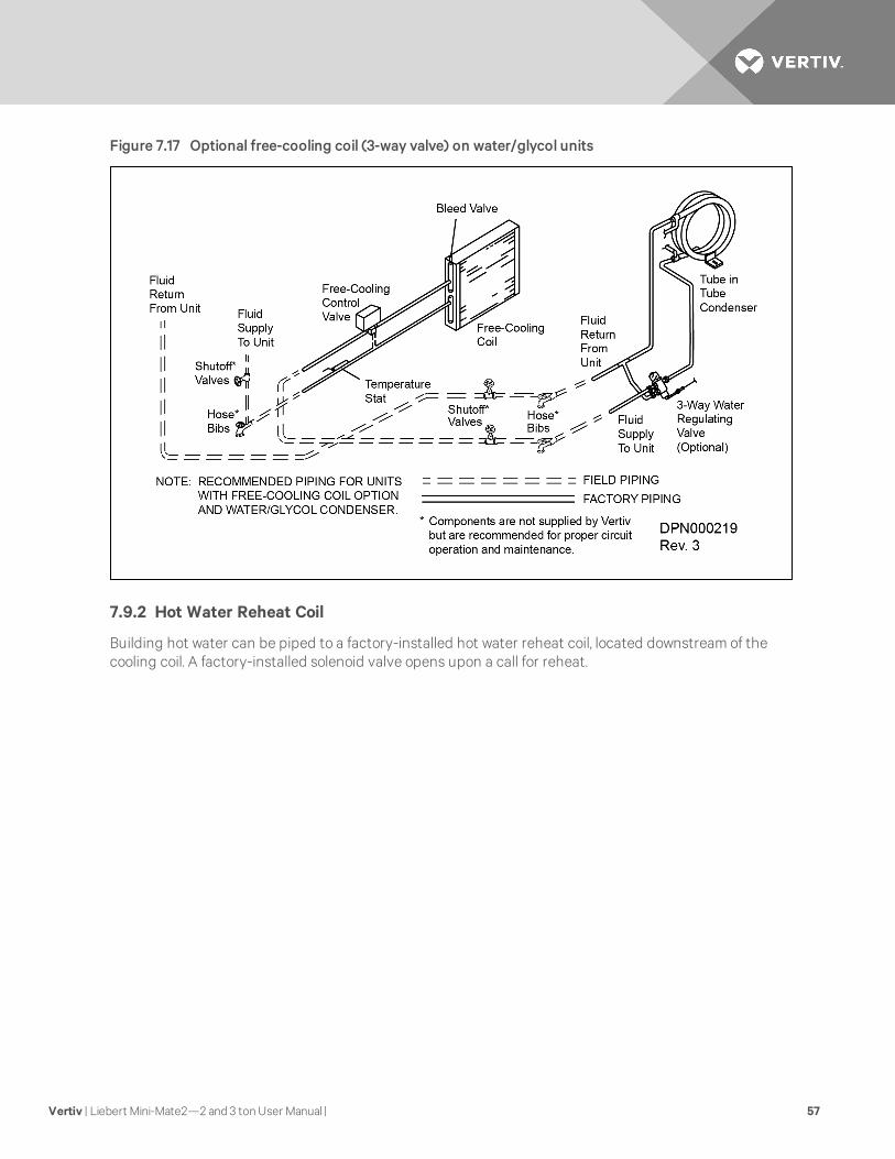
Figure 7.17 Optional free-cooling coil (3-way valve) on water/glycol units
7.9.2 Hot Water Reheat Coil
Building hot water can be piped to a factory-installed hot water reheat coil, located downstream of thecooling coil. A factory-installed solenoid valve opens upon a call for reheat.
Vertiv | Liebert Mini-Mate2—2 and 3 tonUser Manual | 57

Figure 7.18 Optional hot water reheat (two-way valve)
Vertiv | Liebert Mini-Mate2—2 and 3 tonUser Manual | 58

7.10 Checklist for Completed Installation
1. Proper clearance for service access have been maintained around the equipment.
2. Equipment is level and mounting fasteners are tight.
3. Piping completed to refrigerant or coolant loop (if required). Refrigerant charge added (ifrequired).
4. Condensate pump installed (if required).
5. Drain line(s) connected/and checked for leaks.
6. Water supply line connected to humidifier (if required).
7. All piping connections are tight.
8. Field provided pan with drain installed under all ducted cooling units and water/glycolcondensing units.
9. Filter box installed on ducted units.
10. Ducting completed or optional plenum installed.
11. Filter(s) installed in return air duct.
12. Line voltage to power wiring matches equipment nameplate.
13. Power wiring connections completed between disconnect switch, evaporator and condensingunit, including earth ground.
14. Power line circuit breakers or fuses have proper ratings for equipment installed.
15. Control wiring connections completed to evaporator and condensing unit (if required,including wiring to wall-mounted control panel and optional controls).
16. Control panel DIP switches set based on customer requirements.
17. All wiring connections are tight.
18. Foreign materials have been removed from in and around all equipment installed (shippingmaterials, construction materials, tools, etc.)
19. Fans and blowers rotate freely without unusual noise.
20. Inspect all piping connections for leaks during initial operations. Correct as needed.
21. Drain pan is installed under ducted cooling unit and ceiling mounted condensing unit.
22. Rubber band is removed from evaporator condensate pan float switch.
Vertiv | Liebert Mini-Mate2—2 and 3 tonUser Manual | 59

Vertiv | Liebert Mini-Mate2—2 and 3 tonUser Manual | 60
This page intentionally left blank.

8 MICROPROCESSOR CONTROLThe Microprocessor Control for the Liebert Mini-Mate2 features an easy to-use, menu-driven liquidcrystal display. The menus, control features and circuit board details are described in this section.Detailed information concerning controls (System Performance Microprocessor Controls on page 73) andalarms (Alarms on page 77) are provided.
8.1 Feature Overview
To turn the unit ON, press the ON/OFF (I/O) key after power is applied. To turn the unit OFF, press theON/OFF (I/O) key before power is disconnected.
The following control keys may be used to move through the menus, as prompted on the LCD:
• On/Off (I/O): Turns unit on or off (top far left).
• Menu: Enables user to access the program menu to change control parameters, alarms,setback schedule, etc. (top near left).
• Up Arrow: Increases the value of displayed parameter while in a set mode (setpoints, time, etc.)(Arrow-top near right).
• Fan Speed (HI/LO): Changes the fan speed between high and low fan speed on direct-driveblower models; not available on high-static belt-driven motor (bottom far left, when present).
• Escape (ESC): Allows user to move back to a previous menu (top far right).
• Alarm Silence/? (Help): If an alarm is present, pressing this key will silence he alarm. If this key ispressed when no alarms are present, help text will appear (bottom near left).
• Down Arrow: Decreases the value of displayed parameter while in a set mode (bottom nearright).
• Enter (ENTER): After setting a control point, press Enter to store the information in themicroprocessor (bottom far right).
Figure 8.1 Control key locations—all-mounted display box
Vertiv | Liebert Mini-Mate2—2 and 3 tonUser Manual | 61

Active alarms appear on the LCD and sound an audible beeper. To silence an alarm, press theAlarm Silence/Help key as prompted on the display.
Setpoints, DIP switch settings and other selections were made during factory testing of your unit and arebased upon typical operating experience. (Other default selections were made according to optionsincluded with your unit). MAKE ADJUSTMENTS TO THE FACTORY DEFAULT SELECTIONS ONLY IFTHEY DO NOT MEET YOUR SPECIFICATIONS.
Allowable ranges are displayed by pressing the help key. A password will be required (if enabled) tochange setpoints, time delays, etc.
The display normally shown includes the present room temperature, humidity, active status functions(cooling, heating, dehumidifying, humidifying), normal fan speed/low fan speed and active alarms. TheStatus Display may also be selected from the Main Menu.
8.2 Main Menu <Menu>
Press the MENU key to display the Main Menu. The Menu selections (in the following order) include:
SETPOINTS CALIBRATE SENSORS
STATUS ALARM ENABLE
ACTIVE ALARMS ALARM TIME DELAY
TIME COMMON ALARMENABLE
DATE CUSTOM ALARMS
SETBACK CUSTOM TEXT
SETUP OPERATION DIAGNOSTICS
SETPOINTPASSWORD END OFMENU
SETUP PASSWORD
Use the Up/Down arrow to scroll through the selections. When ready to select a particular function pressEnter.
Vertiv | Liebert Mini-Mate2—2 and 3 tonUser Manual | 62

8.3 Setpoints
Setpoints and system setup parameters are kept in nonvolatile memory. Selecting SETPOINTS from theMain Menu will display the following selections:
• TEMPERATURE SETPOINT
• TEMPERATURE SENSITIVITY
• HUMIDITY SETPOINT
• HUMIDITY SENSITIVITY
• HIGH TEMPERATURE ALARM
• LOW TEMPERATURE ALARM
• HIGH HUMIDITY ALARM
• LOW HUMIDITY ALARM
Scroll through this submenu by using the Up/Down arrow, then press Enter to select a particular function.To change a particular value, press Enter and use the Up/Down arrows to change the value. When thevalue has been changed press Enter to store the value. For example to change the temperature setpointfrom the main status display.
1. Press the Menu key to display the main menu.
2. Scroll to “SETPOINTS” using the Up/Down arrow key. Press the Enter key.
3. Scroll to “TEMP SETPOINT” using the Up/Down arrow key. Press the Enter key.
4. Use the Up/Down arrow to change the value. Press the Enter key.
Setpoint Default Range
Temperature Setpoint 72°F 40-90°F (5-32°C)
Temperature Sensitivity 2.0°F 1-9.9°F (0.6-5.6°C)
Humidity Setpoint 50% 20-80% RH
Humidity Sensitivity 5% 1-30% RH
High Temperature Alarm 80°F 35-95°F (2-35°C)
Low Temperature Alarm 65°F 35-95°F (2-35°C)
High Humidity Alarm 60% 15-85% RH
Low Humidity Alarm 40% 15-84% RH
Table 8.1 View default setpoints andallowable ranges
8.4 Status
The operator can monitor the percentage heating, cooling, dehumidifying and humidifying status of theunit by selecting the “STATUS” sub-menu.
8.5 Active Alarms
The operator can monitor the alarms status by selecting “ALARMS” which will display a “No AlarmPresent” or “Alarm XX of YY” alert and description. If more than one alarm is activated, use the Up/DownArrow to scroll through the alarms list. (“XX” reference is the number of the alarm shown, while the “YY”reference is the total number of alarms activated).
Vertiv | Liebert Mini-Mate2—2 and 3 tonUser Manual | 63

8.6 Time
The controller clock must be set to allow for the setback control. The clock uses the 24-hour system (i.e.,12 midnight is displayed as 24:00). To change the time, press Enter to select the function, then use theUp/Down arrow to change the first character, press Enter to store, then press the Up/Down arrow tochange the section character, press Enter to store, etc. THERE IS A BATTERY BACKUP FOR THE DATEAND TIME FEATURES.
8.7 Date
The controller date must be set to allow for the setback control. To change the date press “Enter,” thenuse the Up/Down arrow to change the first character, press Enter to store, press the up/down button tochange the second character, etc.
8.8 Setback
The microprocessor can be programmed for night and weekend setback. Two (2) events can beprogrammed per day for a five-day workweek and two (2) events can be programmed for a two-dayweekend. Table 8.2 below can be used to devise a setback plan.
Event Weekend Weekday
Time 1
Temperature 1
Sensitivity 1
Humidity 1
Humidity Sensitivity 1
Time 2
Temperature 2
Sensitivity 2
Humidity 2
Humidity Sensitivity 2
Table 8.2 Microprocessor night and weekend setback
8.9 Setup Operation
Selecting Setpoint/Setup from the Main Menu will display the following selections:
• RESTART TIME DELAY
• C/F DEGREES
• HUMIDITY CONTROL METHOD
Use the Up/Down Arrow to scroll through the submenu. Press Enter to select a particular function.
8.9.1 Restart Time Delay
This function delays unit restart after main power is restored to the unit. If several systems are operating,the time delays should be set to different values to cause a sequential start. Delay can be set from 0.1 to9.9 minutes (6 to 594 seconds). Setting the value to zero (0) will prevent unit restart when power isrestored. In this case, the unit must be restarted manually by pressing the “ON/OFF” button on thekeypad.
Vertiv | Liebert Mini-Mate2—2 and 3 tonUser Manual | 64
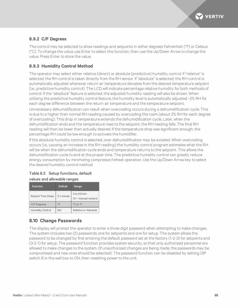
8.9.2 C/F Degrees
The control may be selected to show readings and setpoints in either degrees Fahrenheit (°F) or Celsius(°C). To change the value use Enter to select this function, then use the Up/Down Arrow to change thevalue. Press Enter to store the value.
8.9.3 Humidity Control Method
The operator may select either relative (direct) or absolute (predictive) humidity control. If “relative” isselected, the RH control is taken directly from the RH sensor. If “absolute” is selected, the RH control isautomatically adjusted whenever return air temperature deviates from the desired temperature setpoint(i.e., predictive humidity control). The LCD will indicate percentage relative humidity for both methods ofcontrol. If the “absolute” feature is selected, the adjusted humidity reading will also be shown. Whenutilizing the predictive humidity control feature, the humidity level is automatically adjusted ~2% RH foreach degree difference between the return air temperature and the temperature setpoint.Unnecessary dehumidification can result when overcooling occurs during a dehumidification cycle. Thisis due to a higher than normal RH reading caused by overcooling the room (about 2% RH for each degreeof overcooling). This drop in temperature extends the dehumidification cycle. Later, when thedehumidification ends and the temperature rises to the setpoint, the RH reading falls. The final RHreading will then be lower than actually desired. If the temperature drop was significant enough, thepercentage RH could be low enough to activate the humidifier.If the absolute humidity control is selected, over-dehumidification may be avoided. When overcoolingoccurs (i.e., causing an increase in the RH reading) the humidity control program estimates what the RHwill be when the dehumidification cycle ends and temperature returns to the setpoint. This allows thedehumidification cycle to end at the proper time. The predictive humidity control can greatly reduceenergy consumption by minimizing compressor/reheat operation. Use the Up/Down Arrow key to selectthe desired humidity control method.
Function Default Range
Restart Time Delay 0.1 minute0 to 9.9 min
(0 = manual restart)
C/F Degrees °F °C or °F
Humidity Control Rel Relative or Absolute
Table 8.3 Setup functions, defaultvalues and allowable ranges
8.10 Change Passwords
The display will prompt the operator to enter a three digit password when attempting to make changes.The system includes two (2) passwords: one for setpoints and one for setup. The system allows thepassword to be changed by first entering the default password set at the factory (1-2-3) for setpoints and(3-2-1) for setup. The password function provides system security, so that only authorized personnel areallowed to make changes to the system. (If unauthorized changes are being made, the passwords may becompromised and new ones should be selected). The password function can be disabled by setting DIPswitch 8 in the wall box to ON, then resetting power to the unit.
Vertiv | Liebert Mini-Mate2—2 and 3 tonUser Manual | 65

8.11 Calibrate Sensors
The temperature and humidity sensor can be calibrated by selecting the CALIBRATE SENSORS menuitem. The temperature sensor can be calibrated ±5°F (2.8°C), while the humidity sensor can be calibrated±10% RH. When calibrating the humidity sensor, the value shown will always be % RH, even thoughabsolute humidity control may be selected. If absolute humidity control is selected, the Normal StatusDisplay will display the adjusted reading. This reading may not agree with the relative humidity readingdisplayed while in calibration.If the sensors are subject to frequent wide temperature and humidity swings, it may be necessary toshorten the cycling by increasing the sensor time delay. If the sensors are located too close to the airdischarge, they will likely experience rapid swings in measurement. Another method in reducingcompressor cycling is to increase the temperature and/or humidity sensitivity.
8.12 Alarm Enable
Each alarm can be disabled or enabled. Use the Up/Down Arrow to select a particular alarm, press Enter toselect either enable or disable. Then press Enter again to store the change. When the alarm is disabled itwill NOT report to either the wall box beeper or the common alarm relay.
NOTE: The high water alarm will automatically shut the unit off, even if the alarm is disabled. similarly,optional factory-installed smoke sensor is wired to shut the evaporator unit Off, regardless of theenable/disable status.
8.13 Alarm Time Delay
Each individual alarm can be programmed with a time delay, causing the unit to delay a specified amountof time (0-255 seconds) before recognizing the alarm. See Table 8.4 below for the default times. Thealarm condition must be present for the full amount of the time delay before the alarm will sound. If thealarm condition is diverted prematurely, the alarm will not be recognized and the time delay time willautomatically reset.
NOTE: For software alarms such as loss of power and short cycle, the time delay should be left at thefactory default of 0.
AlarmDefault TimeDelay (seconds)
Humidifier Problem 2
High Head Pressure 2
Custom Alarm #1 0
Custom Alarm #2 6
High Temperature 30
Low Temperature 30
High Humidity 30
Low Humidity 30
Short Cycle 0
Loss of Power 0
Table 8.4 Alarm default timedelays
Vertiv | Liebert Mini-Mate2—2 and 3 tonUser Manual | 66

8.14 Common Alarm Enable
Each individual alarm can be selected to activate/deactivate the common alarm relay. If the energizecommon alarm function is set to YES, the relay is energized immediately as the alarm is annunciated andde-energized when the alarm condition is diverted after the alarm has been recognized. If the alarm iscompletely DISABLED, the alarm has no effect on the common alarm relay. Use the Up/Down arrows toscroll to a particular alarm, press the Enter button to select it, then press the Enter button again to selectYes or No.
8.15 Custom Alarms
The custom alarm messages can be selected from a list of standard alarm messages, or the operator maywrite his/her own message. A MAXIMUM OF TWO (2) ALARM MESSAGES CAN BE CUSTOMIZED. The twocustom alarm messages will initially display the previously programmed message but can be changed.
The text for custom alarms can be changed at any time by selecting “CUSTOM ALARMS”. To change thetext for a custom alarm, select the alarm you would like to change, 1 or 2. Using the Up/Down Arrows, stepthrough the list of five standard alarm messages (listed below) and two custom alarms. Select the alarmmessage desired and store it by pressing Enter.
8.15.1 Standard Custom Alarm Messages
• WATER FLOW LOSS
• SMOKE DETECTED
• LOSS OF AIR FLOW
• HUMIDIFIER PROBLEM
• FILTER CLOG
8.16 Custom Text
To modify the two custom alarm messages select “CUSTOM TXT”. Then select “CUS TXT #1” or “CUS TXT#2”. Text can be up to 20 characters in length and can be either a blank space or any of the followingalphanumeric characters and symbols:
• A,B,C,D,E,F,G,H,I,J,K,L,M,N,O,P,Q,R,S,T,U,V,W,X,Y,Z
• #,%,*,-
• 0,1,2,3,4,5,6,7,8 or 9
Use the Up/Down Arrows to select a character, then press Enter. The cursor will move to the next spacewhere you may once again use the Up/Down Arrows to select another character, etc.
LCD Contrast
The level of contrast due to the viewing angle of the Liquid Crystal Display (LCD) can be adjusted using apotentiometer screw, inside the wall box next to the display.
Nonvolatile Memory
All critical information is stored in nonvolatile memory. Setpoints and setup parameters are kept inside themicrocontroller in EEPROM.
Vertiv | Liebert Mini-Mate2—2 and 3 tonUser Manual | 67

Equipment Options Switches
Equipment options are selected and enabled using DIP switches 1 through 7. These are on the controlboard near TB1. These switches are factory-set and should not require any user changes. The setting andfunction of the switches can be individually read on the LCD.
NOTE: In order to update the DIP switch settings, power must be cycled Off, then On, from the unitdisconnect switch.
Switch OFFPosition ON Position
1 Compressor Chill Water
2 Staged Reheat SCR Reheat
3 Not Used--Must remain in OFF position
4 Not Used--Must remain in OFF position
5 Enable Reheat Disable Reheat
6 Enable Humidifier Disable Humidifier
7 Enable Dehumidifier Disable Dehumidifier
8 Electric Reheat Gas Reheat
Table 8.5 Equipment switch settings(unit control board)
Switch OFFPosition ON Position
1 Disable Beeper Enable Beeper
2 Not Used--Must remain in OFF position
3 Not Used--Must remain in OFF position
4 Not Used--Must remain in OFF position
5 Not Used--Must remain in OFF position
6 Compressor on continuously for tight control Economy Mode
7 Disable Setback Enable Setback
8 Enable Password Disable Password
Table 8.6 Switch settings (wall box board)
8.17 Run Diagnostics (Available On Rev 1.001.0 and Higher)
By selecting Run Diagnostics, maintenance personnel can check system inputs, outputs and conduct atest of the microcontroller circuit board from the wall box control. A review of the system inputs and themicrocontroller test can be done without interrupting normal operation.
Vertiv | Liebert Mini-Mate2—2 and 3 tonUser Manual | 68

Show Inputs
With the unit on and the fan running, the input states may be displayed for the following devices:
High Water Alarm: Normally off unless High Water Alarm is active.
• High Head Pressure Alarm: Normally Off unless High head Pressure alarm is active.
• Custom alarm #1: Normally Off unless this special customer selectable alarm is active.
• Custom alarm #2: Normally Off unless this special customer selectable alarm is active.
• Power: Normally On unless unit is turned off through the wall box, or any of these optionaldevices: high temperature sensor, smoke detector, high water alarm or remote shutdown
Test Outputs
When this feature is selected, the unit is effectively turned Off. When stepping from one load to the next,the previous load is automatically turned Off. The loads can also be toggled on/ off by selecting “ENTER”.Once turned on, the output will remain on for five minutes unless toggled off or the test outputs functionis exited by selecting “MENU/ESC” (Compressor is limited to 15 seconds on to prevent damage.)
NOTICE
Risk of overheating the compressor during the Test Outputs mode. Can cause compressordamage.
Testing the compressor output for more than a few seconds can damage the compressor. Donot operate the unit in the Test Outputs mode any longer than is necessary fortroubleshooting.
NOTICE
Risk of extended unit operation in the Test Outputs mode for troubleshooting. Can causedamage to unit.
DO NOT operate unit in the Test Outputs mode any longer than is necessary fortroubleshooting
The outputs are:
• Normal Fan: Normal speed fan contactor
• Low Speed Fan: Low speed fan contactor
• Humidifier: Humidifier contactor
• Cool: Compressor contactor
• HGBP: Hot gas bypass valve
• Reheat: Reheat contactor
• Common Alarm: Common alarm relay
NOTE: Fan turned on with all loads.
Test Control Board
By selecting this function, the microcontroller will perform a self test lasting approximately 10 seconds.When the test is complete, the display will show the ROM checksum, ROM part number and firmwarevision number.
Vertiv | Liebert Mini-Mate2—2 and 3 tonUser Manual | 69

Figure 8.2 Control menu
Vertiv | Liebert Mini-Mate2—2 and 3 tonUser Manual | 70

Figure 8.3 Control board (inside evaporator)
TB2-4 Hot Gas Bypass TB1-3 Customer Alarm Connection #2
TB2-3 High Head Alarm Connection TB1-2 Customer Alarm Connection # 1
TB2-2 Heat Rejection TB1-1 Customer Alarm Connection (Common)
TB2-1 Heat Rejection TB3-4 Connection to TB3 Pin 4 of wall box
TB1-9 Condensate Pump Aux Alarm TB3-3 Connection to TB3 Pin 3 of wall box
TB1-8 Condensate Pump Aux Alarm TB3-2 Connection to TB3 Pin 2 wall box
TB1-7 Common Alarm Connection TB3-1 Connection to TB3 Pin 1 of wall box
TB1-6 Common Alarm Connection TB4-2 Site Monitoring Connection (-)
TB1-5 Remote Shutdown TB4-1 Site Monitoring Connection (+)
TB1-4 Remote Shutdown P16 Remote Sensor Connection
Vertiv | Liebert Mini-Mate2—2 and 3 tonUser Manual | 71

Figure 8.4 Wall box board
Vertiv | Liebert Mini-Mate2—2 and 3 tonUser Manual | 72

9 SYSTEM PERFORMANCE MICROPROCESSOR CONTROLSThis section provides a detailed description of how the Liebert Mini-Mate2 responds to operator inputsand room conditions.
9.1 Temperature Control
9.1.1 Cooling/Heating Required
The temperature control program for the microprocessor is based on a calculated percentagerequirement for cooling/heating.
9.1.2 Cooling Operation (Cooling, Compressorized Direct Expansion and Chilled Water)
Cooling is ACTIVATED when the temperature control calculates a requirement for cooling of 100%. It isDEACTIVATED when the cooling requirement drops below 50%. The optional hot gas bypass is energizedwhen a call for cooling occurs, unless there is also a call for dehumidification.
Situation Response
Cooling only ON
Dehumidification only OFF
Cooling with Dehumidification OFF
Table 9.1 Cooling anddehumidification load responseof hot gas bypass
9.1.3 Heating Operation
Electric Heat or Hot Water
The reheat stage is ACTIVATED when the temperature control calculates a requirement of 100%.Conversely, the reheat is DEACTIVATED when the heat requirement is 50% less than the activation point.
Ground Current Detector (GCD)
A Ground Current Detector is factory-installed on all 1-ton through 3-ton Liebert Mini-Mate2 units withreheat. The GCD detects reheat leakage current and shuts down operation of the reheat. A steady greenLED indicates that the reheat is operating properly. A red LED indicates that the reheat has failed andboth the reheat element and GCD need to be replaced.
WARNING! Do not remove or disable the ground current detector. Failure to leave the GCD inplace could result in smoke or fire.
Vertiv | Liebert Mini-Mate2—2 and 3 tonUser Manual | 73

Figure 9.1 Ground current detector
WARNING! Risk of heater element failure, smoke and fire. Can cause building and equipmentdamage, injury or death. Do not remove or disable the ground current detector.
SCR Electric Reheat
The SCR (Silicon Controlled Rectifier) controller proportionally controls the stainless steel reheat featureto maintain the selected room temperature. The rapid cycling made possible by the SCR controllerprovides precise temperature control, while the constant element temperature improves heater life.During operation of the SCR control, THE COMPRESSOR OPERATES CONTINUOUSLY. The heaters aremodulated to provide temperature control. The display status will show when the unit is cooling andheating. The control will automatically lock the compressor cooling to “ON” position, except when thetemperature falls below the low temperature alarm setpoint. Cooling will then be disabled until the roomtemperature reaches this minimum temperature setpoint.
Vertiv | Liebert Mini-Mate2—2 and 3 tonUser Manual | 74

9.2 Humidity Control
9.2.1 Dehumidification/Humidification Required
The humidity control is based on a calculated percentage requirement for dehumidification orhumidification (i.e., the difference between the return air humidity and the humidity setpoint). As thereturn air humidity rises above the humidity setpoint, the percent dehumidification required increasesproportionally from 0% to 100% over a humidity band equal to the humidity sensitivity setting. Theconverse is true for percent humidification requirement.
9.2.2 Dehumidification Operation, Compressorized Direct Expansion (DX) Systems
Dehumidification with the standard configuration is accomplished by operating the compressor withoutthe hot gas bypass active. On cooling units with direct drive motors, the fan will operate at low speedunless the cooling requirement reaches 100%. At that point, the low speed fan is disabled (unlessmanually overridden by the user) until the cooling requirement decreases to 0%. Dehumidification willalso be disabled if the heating requirement exceeds 125%. It will be re-enabled when the heatingrequirement reaches 50%.
9.2.3 Humidification Operation
The canister humidifier is activated when the humidity control calculates a requirement of 100%humidification, and it is deactivated when the humidification requirement falls below 50%.
9.3 Load Control Features
The control system monitors the compressor and prevents it from turning on within a 3-minute period ofbeing off. If this on-off-on cycle occurs too often (e.g., 10 times in a one-hour period), a Short Cycle Alarmwill occur.
9.3.1 Communication
The control system uses a two-wire, RS-422 channel to communicate with Liebert Site Products via aproprietary protocol. A converter board (ECA2) is available to allow communications with a “dumb”terminal or a computer using RS-232 channel. More details are provided in the Site Products and ECA2user manual.The communications channel provides both monitoring and control options, including:
• TEMPERATURE/HUMIDITY: Current temperature and humidity readings.
• STATUS (%): Cooling/heating and humidify/dehumidify operating status.
• PRESENT ALARMS: Alarms currently activated.
• SETPOINTS:
• Temperature Setpoint
• Temperature Sensitivity
• Humidity Setpoint
• Humidity Sensitivity
• High Temperature Alarm
• Low Temperature Alarm
• High Humidity Alarm
• Low Humidity Alarm
• ON/OFF STATUS
• SILENCE ALARM
Vertiv | Liebert Mini-Mate2—2 and 3 tonUser Manual | 75

Vertiv | Liebert Mini-Mate2—2 and 3 tonUser Manual | 76
This page intentionally left blank.

10 ALARMSThe microprocessor control system will audibly and visually signal all ENABLED Alarms (including two (2)custom alarms). These special alarms can be chosen from the optional alarm list and/ or can have theirown fully custom text. The custom alarm inputs are contact closures wired from terminal TB1-1 through anormally open contact to either TB1-2 (alarm 1) or TB1-3 (alarm 2). The alarms can be enabled/disabled(refer to Microprocessor Control on page 61) and a time delay of 0-255 seconds can be set. The alarms canalso be programmed to either sound the alarm & activate the common alarm relay OR to sound the alarmonly.
When a new alarm occurs, it is displayed on the screen and the audible alarm is activated. (Ifcommunicating with a Liebert Site Product, the alarm is also transmitted). The message “PRESS ALARMSILENCE” will prompt the operator to silence the alarm. After the alarm is silenced, the display will returnto the Normal Status Display. Alarms can be reviewed by selecting the “ACTIVE ALARMS” feature. Thealarms can also be silenced through communications with a Liebert Site Products Unit.
Many alarms will reset automatically when the alarm condition is no longer represented and only after ithas been acknowledged by being “Silenced.” The exceptions are:
1. Software alarms (i.e., Loss of Power and Short Cycle) will reset automatically 30 seconds afterbeing silenced or acknowledged; and
2. Specific alarms monitoring overload or high pressure switches may require a manual resetdepending upon the model.
10.1 Standard Alarms: Definitions and Troubleshooting
The following list provides a definition and troubleshooting suggestions for each type of alarm. Refer toTroubleshooting on page 95 for additional details. If you need further assistance, contact your Liebertsupplier. THE CUSTOMER MUST SPECIFY ALARM(S) AT THE TIME OF ORDER. OTHER DEVICES ANDWIRING MAY BE REQUIRED AT THE FACTORY FOR SOME OF THE ALARMS.
10.1.1 Custom Alarms
Custom alarm(s) messages are programmed at the LCD. The message displayed may be included in a listof provided alarms or it may be customized text (for up to 2 alarms). IF CUSTOMIZED TEXT IS USED,MAINTENANCE PERSONNEL SHOULD BE INFORMED OF THE ALARM FUNCTION AND THE REQUIREDACTION.
Vertiv | Liebert Mini-Mate2—2 and 3 tonUser Manual | 77
10.1.2 High Head Pressure
Compressor head pressure is monitored with a pressure-sensor switch. (One SPDT pressure switch isused) for the compressor in the unit.
If head pressure exceeds 400 psig (2785 kPa), the switch opens the compressor contactor and sends aninput signal to the control. The high head pressure condition is acknowledged by pressing the alarmsilence button on the wall box, which will clear the alarm if the high head pressure condition no longerexists. If the compressor is off for 1 hour, the control goes into a special cold start mode. In the cold startmode on a call for cooling or dehumidification, the liquid line solenoid valve (LLSV) is energized. If the highpressure switch does NOT trip within 10 seconds, the control returns to normal operation of monitoringthe high head pressure switch for three occurrences in a 12 hour period. It is a rolling timer and after thethird high head alarm occurs and is acknowledged by the user, it will lock off the compressor.
If while in the cold start mode, the high head pressure switch DOES trip within 10 seconds of the activationof the LLSV, the control does not annunciate the alarm. The control will turn off the LLSV and delay 10seconds. The control will permit this occurrence two more times or a total of 3 times. If on the fourth try,the high head pressure switch trips within 10 seconds, the control will annunciate the alarm, turn off theLLSV, wait for the user to acknowledge the alarm and hold the compressor off for 3 minutes, the length ofthe normal short cycle control. The control will permit this occurrence three times. On the thirdoccurrence, the control will lock the compressor off until the control power is reset.
Air-Cooled Systems
Check for power shut off to the condensing unit, condenser fans not working, defective head pressurecontrol valves, closed service valves, dirty condenser coils or crimped lines. Also, make sure that when thecompressor contactor is energized, the side switch on the contactor closes to energize the control circuiton the condensing unit.
Water/Glycol/ Systems
Check water regulating valves. Verify water/glycol flow (i.e., pumps operating and service valves open). Iswater tower or drycooler operating? Is the coolant temperature entering the condenser at or below designconditions? Is AUX relay (terminals 70 & 71) operating during cooling to turn on the drycooler?
10.1.3 Humidity Level
The humidity level alarm may be activated under the following conditions:
• High: The room return air humidity exceeds the pre-set high humidity alarm set point. Is theunit set up for dehumidification? Check DIP switch.
• Low: The room return air humidity decreases to the high humidity alarm set point. Is the unitset up for humidification? Check DIP switch.
• High and Low Humidity (simultaneously): The simultaneous display of two alarms results in lossof the humidity input signal. DASHES WILL BE DISPLAYED IN THE HUMIDITY READINGDISPLAY Under these conditions, the control system deactivates both humidification anddehumidification. Check for a disconnected cable or failed sensor.
Vertiv | Liebert Mini-Mate2—2 and 3 tonUser Manual | 78

10.1.4 Temperature
The temperature level alarm may be activated under the following conditions:
• High: The room return air temperature increases to the high temperature alarm set point.Check for proper set point value. Is the room load more than the unit can handle (i.e., capacitytoo small)? Make sure cooling components are operating (compressor or valves).
• Low: The room return air temperature decreases to the low temperature alarm set point. Checkfor proper set point value. Make sure all heating components are operating (e.g., contactors,reheats, etc.). Are reheats drawing the proper current (refer to amp rating on nameplate).
• High and Low (simultaneously): The simultaneous display of these two alarms results in loss ofthe temperature input signal (or the humidity is out of sensor range: 15 to 85% RH). Dashes willbe displayed for the temperature reading. The control system will initiate 100% cooling. Checkfor a disconnected cable or a failed sensor.
10.1.5 Humidifier Problem Alarm
The Humidifier Problem Alarm will sound and display a message if any of the following humidifierconditions occur: overcurrent detection; fill system fault or end of cylinder life.
Check fault indicator LED on the humidifier control board:
• Constant LED on = Overcurrent
• 1 second LED Flash = Fill System
• 1/2 second LED Flash = Replace Tank
10.1.6 High Water Alarm
A float switch in the evaporator pan will shutdown the evaporator on a high water level. Clear the drainand reset power to the unit in order to clear the alarm.
10.1.7 Loss of Power
The Loss of Power Alarm will activate (after power is restored to the unit) if the unit has lost power or thedisconnect switch was incorrectly turned off before the unit On/Off switch was pressed. A Liebert remotemonitoring unit (optional) will immediately indicate loss of power.
10.1.8 Short Cycle
A Short Cycle Alarm will occur if the compressor system has exceeded 10 cooling start attempts in a one-hour period. This can be caused by low refrigerant level or room cooling load is small compared tocapacity of the unit. Check for leaks, crimped lines and defective components. If room load is low, increasesensitivity to reduce cycle.
10.2 Optional/Custom Alarms
10.2.1 Change Filter
Periodically, the return air filters in the evaporator must be changed. The Change Filter alarm notifies theuser that filter replacement is necessary. A differential air pressure switch closes when the pressure dropacross the filters becomes excessive. The switch is adjustable using the procedure on the switch label.
Vertiv | Liebert Mini-Mate2—2 and 3 tonUser Manual | 79

10.2.2 High Temperature Sensor—Optional
The optional high temperature sensor is a bi-metal operated sensing device with a closed switch undernormal conditions. Connected between Pins 1-8 and 1-9, this device will shut down the entire unit whenthe inlet air temperature exceeds a preset point.
10.2.3 Smoke Detected
The smoke detector senses the return air, shuts down the unit upon detection and sends visual andaudible alarm. This smoke detector is not intended to function as or replace any room smoke detectionsystem that may be required by local or national codes. Locate source of smoke and follow appropriateemergency procedures.
Vertiv | Liebert Mini-Mate2—2 and 3 tonUser Manual | 80
11 SYSTEM TESTING AND MAINTENANCEThis section describes system testing, maintenance and replacement procedures. Use copies of theMaintenance Inspection Checklist to record preventive maintenance inspections.
WARNING! Risk of electric shock. Can cause injury or death. Open all local and remote electricpower disconnect switches before working within the electrical enclosures. Line side of factorydisconnect remains energized when factory disconnect is Off.
11.1 System Testing
11.1.1 Environmental Control Functions
The performance of all control circuits can be tested by changing the setpoints, which actuates each ofthe main functions.
11.1.2 Cooling
To test the cooling function, set the set point to a temperature of 10°F (5°C) below room temperature. Acall for cooling should register and prompt the equipment to begin cooling cycle. (Disregard anytemperature alarms). Upon completion of testing, return setpoint to the desired temperature.
11.1.3 Heating
Reheat may be tested by setting the setpoint for 10°F (5°C) above room temperature. A call for heatingshould register and prompt the equipment to begin heating cycle. (Disregard any temperature alarms).Upon completion of testing, return set point to the desired temperature.
11.1.4 Humidification
To check humidification, set the humidity set point at RH 10% above the room humidity reading. After ashort delay, the canister will fill with water and steam will be produced. Upon completion of testing, returnthe humidity set point to the desired humidity.
11.1.5 Dehumidification
The dehumidification performance can be tested by setting the humidity set point at R.H. 10% below roomrelative humidity. On cooling units with direct drive motor, the compressor should turn on and the fanshould switch to low speed. Upon completion of testing, return humidity set point to the desired humidity.
11.1.6 High Temperature Sensor—Optional
The optional high temperature sensor is a bi-metal operated sensing device with a closed switch undernormal conditions. Connected between Pins 1-8 and 1-9, this device will shut down the entire unit whenthe inlet air temperature exceeds a preset point.
11.1.7 Smoke Detector Sensor
While the smoke sensor is located in the unit, the optional smoke sensor power supply is located in theelectric panel. It constantly samples return air through a tube. No adjustments are required.
Vertiv | Liebert Mini-Mate2—2 and 3 tonUser Manual | 81

11.1.8 Remote Shutdown
A connection point is provided for remote shutdown devices supplied by the customer. This terminal stripis located on the printed circuit board. (Terminals TB1-4 and TB1-5 are fitted with a jumper when noremote shutdown device is installed).
11.2 Maintenance
11.2.1 Electric Panel
The electric panel should be inspected on a semi-annual basis for any loose electrical connections.
11.2.2 Filters
Filters are usually the most neglected item in an environmental control system. In order to maintainefficient operation, they should be checked monthly and changed as required. ALWAYS TURN POWEROFF BEFORE REPLACING FILTERS.
Filters can be replaced by opening either the hinged door on the return air filter box or the return air grille(plenum version only). Replacement filters are commercially available in several efficiencies.
11.2.3 Direct Drive Blower Package
Monthly inspection of the blower package include: motor mounts, fan bearings and impellers.
Fan Impellers and Motor Bearings
Fan impellers should be thoroughly inspected and any debris removed. Check whether they are tightlymounted on the fan shaft and do not rub against the fan housing during rotation. Although the unit'smotor bearings are permanently sealed and self-lubricating, they should be inspected monthly for signsof wear.
For units with the optional belt drive motor/blower, the drive belt should be checked monthly for signs ofwear and proper tension. Pressing on belts midway between the sheave and pulley should produce from1/2" to 1" (12 to 25mm) of deflection. Belts that are too tight can cause excessive bearing wear.
Belt tension can be adjusted by raising or lowering the fan motor base. Loosen nut above motor mountingplate to remove belt. Turn nut below motor mounting plate to adjust belt tension. If belt appears crackedor worn, it should be replaced with a matched belt (identically sized). With proper care, a belt should lastseveral years.
NOTE: After adjusting or changing the belt, always be certain that motor base nuts are tightened. Thebottom adjustment nut should be finger-tight. The top locking nut should be tightened with a wrench.
Air Distribution
Since all unit models are designed for constant volume air delivery, any unusual restrictions within the aircircuit must be avoided. Note that high efficiency filters can reduce air performance and evaporatorcapacity.
Vertiv | Liebert Mini-Mate2—2 and 3 tonUser Manual | 82

11.2.4 High Static Belt Drive Blower Package (Option)
The High Static Blower option is a belt-driven blower box that is attached to the evaporator box. Belt driveshould be checked monthly for signs of wear and proper tension. The motor sheave should be adjustedper the following chart.
Sheave2-TonUnits @885 CFM (1504 CMH)ESP
3-TonUnits @1250 CFM (2124 CMH)ESP
Turns RPM in. (mm) in. (mm)
5 1450 1.0 (25.4) 0.4 (10.2)
4.5 1510 1.1 (28.8) 0.5 (13.6)
4 1570 1.3 (32.4) 0.7 (17.2)
3.5 1630 1.4 (36.1) 0.8 (20.9)
3 1690 1.6 (40.0) 1.0 (24.7)
2.5 1750 1.7 (44.0) 1.1 (28.7)
2 1810 1.9 (48.1) 1.3 (32.8)
1.5 1870 2.1 (52.4) 1.5 (37.1)
1 1930 2.2 (56.8) 1.6 (41.5)
0.5 1990 2.4 (61.3) 1.8 (46.1)
0 2050 2.6 (66.0) 2.0 (50.8)
Table 11.1 External static pressure available
11.2.5 Refrigeration System
Each month the components of the refrigeration system should be inspected for proper function andsigns of wear. Since in most cases evidence of malfunction is present prior to component failure, periodicinspections can be a major factor in the prevention of most system failures. Refrigerant lines must beproperly supported and not allowed to vibrate against ceilings, floors, or the unit frame. Inspect allrefrigerant lines every six months for signs of wear and proper support. Inspect the capillary and equalizerlines from the expansion valve.
Suction Pressure
Suction pressure will vary with load conditions. Suction pressure normally ranges from 58psi to 75psi(405kPa to 517kPa).
Vertiv | Liebert Mini-Mate2—2 and 3 tonUser Manual | 83

Discharge Pressure
The discharge pressure will vary greatly with load and ambient conditions (see Table 11.2 below). Thehigh-pressure switch will shut the compressor down at its cut-out setting
System Design Discharge Pressure, psig (kPa)
Air-Cooled 200-300 (1380-2070)
Water-Cooled 65 to 85°F water(18 to 29.4°C) 200-250 (1380-1725)
Glycol-Cooled 250-350 (1725-2415)
High-Pressure Cut-Out 400 (2760)
Table 11.2 Typical discharge pressure
Thermostatic Expansion Valve
The thermostatic expansion valve keeps the evaporator supplied with enough refrigerant to satisfy loadconditions. Proper valve operation can be determined by measuring superheat level. If too little refrigerantis being fed to the evaporator, then the superheat will be high. Conversely, if too much refrigerant is beingsupplied, then the superheat will be low. The correct superheat setting is between 10 and 15°F (5.6 and8.3°C).
Air-Cooled Condensing Units
Restricted airflow through the condensing unit coil will reduce the operating efficiency of the unit.Additionally, it can result in high compressor head pressure and loss of cooling. Using compressed air orcommercial coil cleaner, clean the coil of all debris that will inhibit airflow. In winter, do not permit snow toaccumulate around the side or underneath the condenser. At the same time check for bent or damagedcoil fins and repair as necessary. Check all refrigerant lines and capillaries for vibration and support asnecessary. Carefully inspect all refrigerant lines for signs of oil leaks.
Coaxial Condensers (Water/Glycol-Cooled Condensing Units Only)
Each water or glycol-cooled module has a coaxial condenser consisting of an exterior steel tube and aninterior copper tube. If the water supply is clean, coaxial condensers do not normally require maintenanceor replacement. Should your system begin to operate at high head pressure with reduced capacity and allother causes have been eliminated, the condenser may be obstructed or fouled and should be cleaned orreplaced.
Regulating Valves
The water regulating valve automatically regulate the amount of fluid necessary to remove the heat fromthe refrigeration system, permitting more fluid to flow when load conditions are high and less fluid to flowwhen load conditions are low. The valve consists of a brass body, balance spring, valve seat, valve discholders, capillary tube to discharge pressure and adjusting screw.
The water regulating valve is designed to begin opening at 180 psi (1240kPa) and be fully opened at 240psi (1655kPa). The valve is factory-set and should not need adjustment. There is significant difference inthe way standard pressure and high pressure valves are adjusted. Consult Liebert Services.
Vertiv | Liebert Mini-Mate2—2 and 3 tonUser Manual | 84

Glycol Solution Maintenance
It is difficult to establish a specific schedule of inhibitor maintenance since the rate of inhibitor depletiondepends upon local water conditions. Analysis of water samples at time of installation and every six (6)months should help to establish a pattern of depletion. A visual inspection of the solution and filterresidue is often helpful in judging whether or not active corrosion is occurring. The complexity ofproblems caused by water requires expert advice from a water treatment specialist plus a regularmaintenance program schedule. It is important to note that improper use of water treatment chemicalscan cause more severe problems than simply using none.
Proper inhibitor maintenance must be performed in order to prevent corrosion of the glycol system.Consult your glycol manufacturer for proper testing and maintenance procedures. Do not mix productsfrom different manufacturers.
Hot Gas Bypass
Operation
The hot gas bypass valve is installed between the compressor discharge piping and suction piping,bypassing the condenser and evaporator coils. The discharge gas mixes with the suction gas, raising thesuction temperature and pressure and decreasing the mass flow through the evaporator. The highersuction temperatures could cause compressor overheating, therefore a separate liquid quenching valve isprovided to mix refrigerant from the system liquid line with the discharge gas before mixing with thesuction gas entering the compressor.
During normal operation, when the evaporator is under full load the hot gas bypass equalizer pressure willremain high enough to keep the valve port closed. If the evaporator load decreases, the evaporatortemperature and pressure will drop. When the suction pressure reduces below the hot gas bypass valvesetting the hot gas bypass valve opens diverting some of the refrigerant flow back to the compressorsuction. The liquid quenching valve bulb senses this increased superheat and opens, allowing liquidrefrigerant to mix with the discharge gas, desuperheating it.
Proper mixing of the three refrigerant paths ensures stable operation and system performance. The liquidquenching valve bulb must be located downstream of all these connections to control superheat at thecompressor inlet. Superheat settings for the liquid quenching valve are chosen to maintain consistencywith the system expansion valve. During hot gas bypass operation higher superheats, 50-60°F (19-15°C),may be observed at the compressor. The liquid quenching valve is internally equalized and superheat isnot adjustable.
Adjustment
1. Install the suction and discharge pressure gauge.
2. Adjust temperature setpoint to call for cooling so that the refrigeration compressor will runcontinuously.
3. Remove the TOP adjusting nut from the valve.
4. Insert an Allen wrench in the brass hole at top of valve in adjusting port and turn CLOCKWISEif a higher evaporator temperature is required. Adjust no more than 1/4 turn at a time. Let thesystem stabilize for 15 minutes before determining if additional adjustment are necessary.
5. After obtaining the suction pressure required, reinstall cap tightly making sure there are noleaks.
6. Let the evaporator operate for approximately 10 to 15 minutes to make sure the suctionpressure is within the range desired.
Vertiv | Liebert Mini-Mate2—2 and 3 tonUser Manual | 85

7. There may be a fluctuation of approximately 3 to 6 PSIG (21 to 41kPa) on the evaporator due tothe differential on the hot gas bypass.
8. Return temperature setpoint to the desired setting.
Figure 11.1 Hot gas bypass
Steam Generating Humidifier-Operation Procedures
Steam generating humidifiers operate efficiently over a wide range of water quality conditions andautomatically adjust to changes in the conductivity of water. The system will automatically drain and refillto maintain an amperage set point and alert the operator when the humidifier canister needs to bereplaced.
The humidifier RUN/DRAIN switch is located in the humidifier assembly. This switch should be in the RUNposition when the humidifier is in normal operation and in the DRAIN position when a manual drainsequence is required, such as during service. The electronic control board for the humidifier is alsolocated in the humidifier assembly. When the unit is energized, power is available to humidifier. Operationsinvolves the following steps:
1. During start-up, when the humidity control calls for humidification, the fill valve will open,allowing water to enter the canister. When the water level reaches the electrodes, current flowsand the water will begin to warm. The canister fills until the amperage reaches the setpoint andthe fill valve closes. As the water warms, its conductivity increases and the current flow, in turn,rises. If the amperage reaches 115% of the normal operating amperage, the drain valve opensand flushes some of the water out of the canister. This reduces electrode contact with thewater and lowers the current flow to the amperage set point. Boiling soon commences and thecanister operates normally.
2. If the conductivity of the water is low, the canister fills and the water level reaches the canisterfull electrode before the amperage set point is reached. The humidifier stops filling to preventoverflow. Boiling should commence in time. As water is boiled off, the mineral concentration inthe canister increases and current flow also increases. The canister eventually reaches fulloutput and goes to normal operation. No drain is permitted until then.
Vertiv | Liebert Mini-Mate2—2 and 3 tonUser Manual | 86

3. When full output is reached the circuit board starts a time cycle which is factory-set at 60seconds. During this repeating time cycle, the fill valve will open periodically to replenish thewater being boiled off and maintain a “steady state” output at the setpoint. The amperagevariance will depend on the conductivity of the water.
4. After a period of time, the mineral concentration in the canister becomes too high. When thisoccurs, the water boils too quickly. As the water quickly boils off and less of the electrode isexposed, the current flow decreases. When the current crosses the low threshold point(factory-set at 85%) before the end of the time cycle, the drain valve opens, draining themineral laden water out and replacing it with fresh water. This lowers the mineral concentrationand returns the canister to “steady state” operation and prolongs canister life. The frequencyof drains depends on water conductivity.
5. Over a period of time, the electrode surface will become coated with a layer of insulatingmaterial, which causes a drop in current flow. As this happens, the water level in the canisterwill slowly rise exposing new electrode surface to the water to maintain normal output.Eventually, the steady state water level will reach the canister full electrode and indicate so byactivating the canister full alarm. At this point, all of electrode surface has been used up andthe canister should be replaced.
6. After the entire electrode surface has been coated, the output will slowly decrease. This allowsfor maintenance scheduling. During these last hours of electrode life, the mineralconcentration can increase and arcing can occur. If the electrodes start to arc, turn off thehumidifier immediately and replace the canister with the identical part.
11.2.6 Humidifier Circuit Board Adjustments
WARNING! Risk of electric shock. Can cause injury or death. Open all local and remote electricpower disconnect switches before working on the humidifier printed circuit board. The printedcircuit board contains hazardous voltage. Use extreme caution. Circuit board adjustmentshould be performed by properly trained and qualified personnel only.
The humidifier control board governs humidifier operation. There are three potentiometers mounted onthe board and can be used to adjust for extreme water conductivity conditions.
POT2 controls the amperage at which the drain will energize and is clearly marked in percentages. Thisadjustment is factory-set at 85%, which indicates that the unit will drain when the amperage falls off to85% of the capacity set point. Raising the value increases the frequency of drain cycles. Lowering thevalue decreases the frequency of drain cycles.
The frequency should be increased for highly conductive water and decreased for less conductive water.If adjustment is necessary and a change of 3 to 4 percent in either direction does not permit normaloperation of the unit, consult your Liebert supplier.
Vertiv | Liebert Mini-Mate2—2 and 3 tonUser Manual | 87
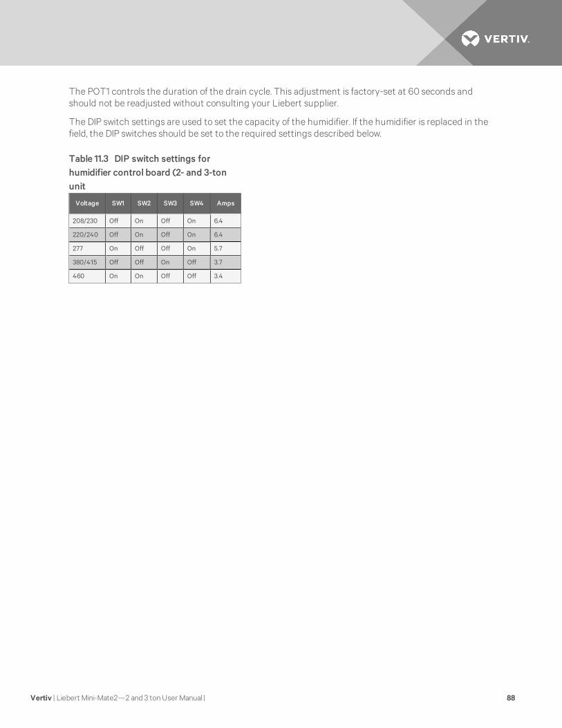
The POT1 controls the duration of the drain cycle. This adjustment is factory-set at 60 seconds andshould not be readjusted without consulting your Liebert supplier.
The DIP switch settings are used to set the capacity of the humidifier. If the humidifier is replaced in thefield, the DIP switches should be set to the required settings described below.
Voltage SW1 SW2 SW3 SW4 Amps
208/230 Off On Off On 6.4
220/240 Off On Off On 6.4
277 On Off Off On 5.7
380/415 Off Off On Off 3.7
460 On On Off Off 3.4
Table 11.3 DIP switch settings forhumidifier control board (2- and 3-tonunit
Vertiv | Liebert Mini-Mate2—2 and 3 tonUser Manual | 88

11.3 Replacement Procedures
11.3.1 Compressor Replacement
Infrequently, a fault in the motor insulation may result in a motor burnout (if system is properly installed,motor burnout rarely occurs). Primarily this type of failure is due to mechanical or lubrication problems,where the burnout is a secondary consequence.
Early detection can prevent a large percentage of the problems that can cause compressor failures.Periodic maintenance inspections by alert service personnel (i.e., identification of abnormal operation) canbe a major factor in reducing maintenance costs. It is easier and more cost-effective to implement thenecessary preventative steps that ensure proper system operation; rather than ignore a problem until itresults in compressor failure and costly replacement. When troubleshooting a compressor problem, checkall electrical components for proper operation:
WARNING! Risk of contacting caustic substances. Can cause injury. Avoid touching orcontacting the gas and oils with exposed skin. Severe burns will result. Wear protectiveclothing, safety goggles and long rubber gloves when handling contaminated parts.
• Check all fuses and circuit breakers.
• Check pressure switch operation.
• If a compressor failure has occurred, determine whether its cause is an electrical or mechanicalproblem.
WARNING! Risk of explosive discharge of high pressure refrigerant. Can cause serious injury.This unit contains fluids and gasses under high pressure. Relieve pressure before working withpiping/connections.
Mechanical Failure: If a mechanical failure has occurred, the compressor must be replaced. If a burnoutoccurs, correct the problem and clean the system. It is important to note that successive burnouts OFTHE SAME SYSTEM are usually caused by improper cleaning. If a severe burnout has occurred, the oil willbe black and acidic.
11.3.2 Electrical Failure
In the event of an electrical failure and subsequent burnout of the refrigeration compressor motor, properprocedures must be followed to thoroughly remove any acids that would cause a future failure. There aretwo kits that can be used with a complete compressor burnout:
• Sporlan System Cleaner
• And Alco Dri-Kleener.
Follow the manufacturer's procedure. DAMAGE TO A REPLACEMENT COMPRESSOR DUE TO IMPROPERSYSTEM CLEANING CONSTITUTES ABUSE UNDER THE TERMS OF THE WARRANTY, THEREBYVOIDING THE WARRANTY.
Vertiv | Liebert Mini-Mate2—2 and 3 tonUser Manual | 89

Replace a Failed Compressor
Proper procedures to remove and replace the failed compressor are:
1. Disconnect power
2. Attach suction and discharge gauges to access fittings.
3. Recover refrigerant using standard recovery procedures and equipment. Use a filter-drierwhen charging the system with recovered refrigerant.
NOTE: Release of refrigerant to the atmosphere is harmful to the environment and unlawful.Refrigerant must be recycled or discarded in accordance with federal, state and local regulations.
4. Remove failed compressor.
5. Install replacement compressor and make all connections. Use a flow of dry nitrogen throughthe piping during brazing to prevent formation of copper oxide scale inside the piping. Copperoxide forms when copper is heated in the presence of air. POE oil will dissolve these oxides frominside the copper pipes and deposit them throughout the system, clogging filter driers andaffecting other system components.
A pure dry nitrogen flow of 1-3 ft3/min (0.5-1.5 l/s) inside the pipe during brazing is sufficient todisplace the air. Control the flow using a suitable metering device.Pressurize and leak test thesystem at approximately 150 psig (1034kPa) pressure.
6. Follow manufacturer's instructions for clean out kits.
7. Evacuate the system twice to 500 microns. Break the vacuum each time with clean, drynitrogen.
8. Evacuate the system a third time to 500 microns.
9. Charge the system with refrigerant (R-407C) based on requirements of the evaporator,condensing unit and lines. Refer to the unit nameplate.
10. Apply power and operate the system. Check for proper operation. Refer to Table 11.2 onpage 84.
11.3.3 Replacing the Humidifier Canister
CAUTION: Risk of contact with extremely hot surfaces. Can cause injury. The canister andsteam hose may be hot. Allow time for the humidifier to cool before replacing parts.
The proper procedure to replace the humidifier canister is:
1. Turn off the humidifier by lowering the humidity setpoint below the ambient humidity level.Record the original setpoint.
2. Place the RUN/DRAIN switch in the DRAIN position to drain the water from the canister.
3. Return the RUN/DRAIN switch to the RUN position after the canister has drained.
4. Turn OFF the power at the main unit electric power disconnect switch.
5. Remove the cover from the humidifier cabinet.
6. Locate the power wires to the steam canister. They are connected to the canister with 1/4"quick connects. Make note of the wiring configuration before removing any wires. Refer toschematic on unit. Slide the rubber boot back to expose the connections. Remove the two (2)power wires and the canister full wire. Do not loosen the screws that secure the electrodes.
Vertiv | Liebert Mini-Mate2—2 and 3 tonUser Manual | 90

7. Loosen the steam outlet hose clamps and slide the steam hose away from the canister fitting.Release the canister clamp along the base of the canister.
8. Remove the canister.
9. Reverse previous steps to re-assemble humidifier, paying special attention to the following:
• When replacing the wiring, connect the red wire from terminal #1 on the interface to thered tip terminal on the canister. Reconnect the power wires as before (#2 on the left and#1 on the right).
• When replacing the canister, always check the fill and drain solenoids for properoperation.
Vertiv | Liebert Mini-Mate2—2 and 3 tonUser Manual | 91

Vertiv | Liebert Mini-Mate2—2 and 3 tonUser Manual | 92
This page intentionally left blank.

12 MAINTENANCE INSPECTION CHECKLIST
Date: ___________________ Prepared By: ___________________
Model #: ___________________ Serial Number: ___________________
NOTE: Reheat element sheaths and fins are manufactured with stainless steel. Regular inspections arenecessary to assure proper cleanliness of the reheating element. Should inspection reveal corrosionparticles on the reheating element or adjoining surfaces (including ducts and plenums), appropriatecleaning should be performed. Periodic reheating element replacement may be required to meetspecific application requirements.
Monthly Inspection Items
Filters Humidifier
1. Check for restricted airflow.2. Check for filter.3. Wipe section clean.
1. Check canister for mineral deposits.2. Check condition of electrodes.3. All hoses and fittings tight.4. Check water make-up valve for leaks.
Fan Section Drain Lines
1. Impellers free of debris2. Bearings in good condition
1. Check for obstructions and sediment buildup.
2. Check for external damage and/or corrosion.3. Check for leaks.
Vertiv | Liebert Mini-Mate2—2 and 3 tonUser Manual | 93

Semiannually
Compressor SectionFlood Back Head Pressure Control (ifapplicable)
1. Signs of oil leaks 1. Check refrigerant level.
2. Vibration isolation. Water or Glycol-Cooled Condensing
Refrigeration Cycle 1. Water valve adjustment.
1. Suction pressure2. Head pressure3. Superheat
4. Water flow5. Water leaks
6. Evaporator coil clean Glycol Pump (if applicable)
7. Insulation intact 1. Glycol leaks
Air-Cooled Condensing Unit (ifapplicable)
2. Pump operation
1. Condenser coil clean. 2. Glycol solution
3. Motor mount tight. 4. pH level
5. Bearings in good condition. Electric Panel
6. Refrigerant lines properlysupported.
1. Check electrical connections.2. Operational sequence
Notes:_______________________________________________________________________________________
Signature: __________________________________________________________________________________
Make photocopies of this form for your records
Vertiv | Liebert Mini-Mate2—2 and 3 tonUser Manual | 94

13 TROUBLESHOOTING
SymptomPossibleCause
CheckOr Remedy
Unit will not start
No power tounit Check voltage at input terminal block.
Controlvoltage circuitbreaker (attransformer)open
Locate short and reset circuit breaker.
Float switchrelay hasclosed due tohigh water inthecondensatepan.
Has rubber band been removed from float switch? Check drain and line. Access from bottom through dischargeair gills. Power must be cycled at the disconnect to reset.
Jumper not inplace
Check terminal TB1-4 and TB1-5 for jumper or N/C contact. Check pins 1-8 and 1-9 for jumper, or N/C hightemperature sensor contact. Check pins 5-4 and 5-5 for jumper or N/C smoke detector contact.
No cooling
“Cooling” isnot displayedat the controlpanel.
Adjust TEMP control setpoint and sensitivity to require cooling.
Short cyclepreventioncontrol.
Control software delays compressor 3 minutes cooling, from stop to start
Compressorcontactor notpulling in.
Check for 24 VAC ± 2 VAC at terminals P4-8 and P4-4. If voltage, check contactor. If no voltage at P4-8 and P4-4, check at terminals P2-3 and P2-8. If voltage, check freezestat.
Compressorhigh headpressure.
See below for cause.
Pluggedfilter/drier. Replace filter/dryer.
Lowrefrigerantcharge.
Check pressure gauges. See Table 7.11 on page 36 and Table 7.13 on page 37 for recommended pressures. Atlow ambient temperatures, proper refrigerant charge is very important on units with Lee-Temp receivers.
Compressor highhead pressure
Insufficient airflow acrosscondensercoil
Remove debris from coil and air inlets.
Water/Glycol-cooled only:No fluidflowingthroughcondenser.
Check fluid supply to regulating valve. Adjust valve if necessary.
Self-Contained,Air-Cooledonly:Condenserfan notoperating
Check fan operation.
Table 13.1 Troubleshooting
Vertiv | Liebert Mini-Mate2—2 and 3 tonUser Manual | 95

SymptomPossibleCause
CheckOr Remedy
Humidifier doesnot operate
DIP switch notset to enablehumidifieroption
See DIP switch setting Table 11.3 on page 88.
“HUMIDIFY”not displayedat controlpanel
Increase humidity control setpoint and sensitivity to require humidification.
Defectiveboard
Check voltage at P3-1 and P1-9 on interface board for 24VAC ± 2VAC. If no voltage, check wiring and/or replaceboard. Check wiring from control panel to board.
Failedhumiditysensor
Humidity display will indicate dashes. Check wiring from temperature/humidity board to the control board andfrom the wall box to the control board. Replace wall box or temperature/humidity circuit board (if remote).
No water flow Make sure switch is in Run position. Check humidifier water supply (including filter screen) and check nylonoverflow line if canister is full.
Canister fillrate is notkeeping upwith thesteam output.
Check fill valve screen opening and capillary tube for obstructions. Check water supply pressure (minimum 10PSIG).
Reheat will notoperate
DIP switch notset to enablereheat option
See DIP switch settings Table 11.3 on page 88
“HEAT” notdisplayed atthe controlpanel
Increase temperature set point to require heating.
Reheat safetyopen,defectivereheatcontact ordefectiveboard
Check voltage at P2-1 and P1-9 on interface board for 24 VAC ± 2 VAC. If voltage, check reheat contactor andreheat safety. If no voltage, check wiring and/or replace board.
Element isburned out Turn off power. Check element continuity with Ohm meter.
GCD hastripped Replace GCD and heating element.
Fan will notoperate at lowspeed whenselected fromcontrol panel.
Open wiringor failed board
Verify “LOW FAN” is displayed at the control panel. Check for 24 VAC ± 2 VAC at terminals P3-4 and P1-9. If novoltage, check wiring and/or replace interface board. Check fan relays.
Fan will notoperate at lowspeed duringdehumidification
Temperaturerequirementis too high.
Verify with display. Cooling requirement overrides Dehumidification.
Cooling cycle tooshort
Sensorresponsedelay tooshort
Increase sensor response delay. See Calibrate Sensors on page 66.
Display freezesand control padsdo not respond
Staticdischarge
During period of low humidity, static electricity can cause the control program to freeze or display incorrectinformation. Although this is unlikely, the control can be reset by cycling power from the disconnect switch.
Condensatepump does notoperate
Open or shortcircuit inwiring
Find open or short circuit and repair power to pump.
Table 13.1 Troubleshooting (continued)
Vertiv | Liebert Mini-Mate2—2 and 3 tonUser Manual | 96

SymptomPossibleCause
CheckOr Remedy
ContinuousCooling*
Failedtemperaturesensor
Temperature display will indicate dashes. Check wiring from temperature/humidity board (remote sensors) tothe control board or from control board to wall box. Replace temperature/humidity circuit board (remotesensors) or wall box.
ContinuousHeating*Dehumidification*Humidification*
Shortedwiring orfailed controlboard
Check wiring and/or replace control board.
Display Problem Incorrectwiring
Review section Electrical Connections on page 43. Verify VDC between 5 and 6 Volts at TB-3 Pin 1 (Ground) andTB-3 Pin 2 of the control board and wall box. If the transmit lines (TB-3 Pin 3 & 4) are not connected, only thepower LED will be lit. It will flash once every 10-12 second. If T- is connected, but not T+, TX1 will flashapproximately every 2-3 second. And the power LED will flash once every 10-12 second. If T+ and T- arereversed, the power LED and RX1 Will be lit and flash every 10-12 second.
NOTE: Erratic operation of the unit could occur. If no LED is lit, there is no power or the +5VDC polarity isreversed. If any of these conditions occur, remove power from the evaporator using the disconnect switch, andcorrect wiring from the control board to the wall box.
NOTE: It may take up to 20 seconds for the display to appear on the wall box LCD after power is applied.
Table 13.1 Troubleshooting (continued)
Vertiv | Liebert Mini-Mate2—2 and 3 tonUser Manual | 97

Vertiv | Liebert Mini-Mate2—2 and 3 tonUser Manual | 98
This page intentionally left blank.


VertivCo.com | Vertiv Headquarters, 1050 Dearborn Drive, Columbus, OH, 43085, USA
© 2017VertivCo. All rights reserved. Vertiv and the Vertiv logo are trademarks or registered trademarks of VertivCo. All other names and logos referred toare trade names, trademarks or registered trademarks of their respective owners. While everyprecaution has been taken to ensure accuracyandcompleteness herein, VertivCo. assumes no responsibility, and disclaims all liability, for damages resulting from use of this information or for anyerrors oromissions. Specifications are subject to change without notice.
SL-10531_REV4_10-17/590-1774-501A