Embed Size (px)
Citation preview

Liebert® SRC™
Mini-Split Cooling System
Installer/User Guide

Technical Support Site
If you encounter any installation or operational issues with your product, check the pertinent section ofthis manual to see if the issue can be resolved by following outlined procedures. For additional assistance,visit https://www.VertivCo.com/en-us/support/

TABLE OF CONTENTS
1 Important Safety Instructions 7
2 Model Number Nomenclature 13
2.1 Model-number Nomenclature Detail 13
3 Product Introduction 15
3.1 Electrical Data 21
3.2 R-410A Refrigerant 22
4 Pre-installation Preparation and Guidelines 23
4.1 Selecting the Location for the Outdoor Unit 23
4.1.1 Ambient-air Conditions 24
4.1.2 Oceanside Applications 24
4.2 Clearance Requirements 26
4.2.1 Outdoor Unit Clearance 27
4.2.2 Indoor Unit Clearance 29
5 Installation 31
5.1 Mounting the Outdoor Unit 31
5.1.1 Mounting-platform Guidelines 31
5.1.2 Tie-down and Wind-restraint Guidelines 32
5.1.3 Considerations for Snow and Ice Conditions 32
5.2 Installing a Wind Baffle on the Outdoor Unit 32
5.2.1 Precautions for Wind Baffle Installation 32
5.2.2 Wind-baffle Assembly Inspection and Installation 32
5.3 Installing the Indoor Unit 34
5.3.1 Mounting the Installation Plate to the Wall (SRC18) 34
5.3.2 Mounting the Installation Plate to the Wall (SRC24 and SRC36) 36
5.3.3 Drilling a Piping Hole in the Wall 38
5.3.4 Installing the Optional Condensate Pump 39
5.3.5 Mounting the Indoor Unit to the Plate 43
5.3.6 Prepare for Piping/Electrical Connection 45
5.4 Pump Down Procedure 46
6 Installation Checklist 49
7 Piping Requirements 51
7.1 Creating a Flare Fitting 51
7.2 Tightening Flare Nuts 53
7.2.1 Loosening Flare Nuts 54
7.3 Piping Materials and Handling 54
7.3.1 Brazing Practices 56
7.3.2 Refrigerant-piping Insulation Guidelines 56
7.3.3 Selecting Field-supplied Copper Tubing 57
7.3.4 No Pipe Size Substitutions 58
7.3.5 Obstacles 58
Vertiv | Liebert SRC Installer/User Guide | 3

7.3.6 Copper Expansion and Contraction 59
7.3.7 Pipe Bends 62
7.3.8 In-line Refrigeration Components 62
7.3.9 Field-provided Isolation Ball Valves 62
7.3.10 Using Elbows 62
7.3.11 Pipe Supports 62
7.3.12 Pipe Sleeves at Penetrations 64
7.3.13 Underground Refrigerant Piping 65
7.4 Piping Connections 66
7.4.1 Connection Limitations 66
7.4.2 Piping Connections Layout 66
7.4.3 Routing the Drain Hose for Indoor Unit 70
7.4.4 Installing a Drain Hose on the Outdoor Unit 72
7.4.5 Connecting Piping on the Outdoor Unit 73
7.4.6 Connecting Piping on the Indoor Unit 75
7.5 Insulating Refrigeration Piping 79
7.5.1 Minimum Requirements for Wall Thickness of Ethylene Propylene Diene Methylene (EPDM) Pipe Insulation 81
7.6 Air Purging 82
7.6.1 Piping Leak Test 84
7.6.2 Evacuation 86
7.6.3 Removing Purge and Test Equipment 87
8 Electrical Connections 89
8.1 Power-supply and Power-wiring Specifications 89
8.2 Communication-cable Specifications 92
8.3 Communication Cables between the Unit and Controller 92
8.4 Connecting Outdoor Unit Electrical Wiring 92
8.5 Thermostat Installation and Wiring 94
9 Installation Set-up and System Start-up 101
9.1 Accessing Installer Set-up Mode 101
9.2 Running Test Mode 103
9.3 Setting the Address of Central Control 103
9.4 Setting E.S.P. 104
9.5 Setting the Thermistor 104
9.6 Setting the Ceiling Height 105
9.7 Setting Fahrenheit/Celsius 106
9.8 Setting Optional Functions 106
9.9 Setting Temperature Range 106
10 Operation 109
10.1 Operating the Unit 109
10.2 Automatic Unit Restart 109
10.3 Enabling Cooling-only Mode 110
10.4 Disabling Cooling-only Mode 110
Vertiv | Liebert SRC Installer/User Guide | 4

10.5 Standard Operation 111
10.5.1 Selecting Cooling Mode 111
10.5.2 Selecting Power Cooling 111
10.5.3 Selecting Heating Mode 111
10.5.4 Selecting Dehumidification Mode 112
10.5.5 Selecting Fan Mode 112
10.5.6 Selecting Auto Mode 112
10.5.7 Selecting Timed Override 113
10.5.8 Selecting Set Back 113
10.5.9 Setting the Temperature 113
10.5.10 Adjusting Air Flow 113
10.5.11 Selecting Energy-saving Cooling 114
10.5.12 Selecting Automatic Drying 114
10.5.13 Selecting Fan Auto 114
10.6 Function Settings 114
10.6.1 Setting Louver Angle Control 114
10.6.2 Locking the Display 115
10.6.3 Setting the Minimum Difference between the Cooling and Heating Setpoints 115
10.6.4 Setting Current Time 115
10.6.5 Setting Override Time 115
10.6.6 Setting Set-back Temperature 116
10.6.7 Clearing the “Clean Filter” Alarm 116
10.7 Schedule Set-up 116
10.7.1 Simple Schedule 116
10.7.2 Setting a Sleep Schedule 116
10.7.3 Setting a Weekly Schedule 117
10.7.4 Copying/Pasting a Schedule 117
10.7.5 Scheduling a Holiday 118
10.7.6 Delete all Schedules 118
11 Maintenance 119
11.1 Cleaning the Air Filter 120
11.1.1 Cleaning the Air Filter on Type 1 Units 120
11.1.2 Cleaning the Air Filter on Type 2 Units 121
11.2 Cleaning the Optional 3M or Triple Filter 122
12 Troubleshooting 125
12.1 Self-diagnosis at the Indoor Unit 125
12.2 Before Calling for Service 125
12.3 Self-diagnosis at the Thermostat 125
12.4 Troubleshooting Error Codes at the Indoor and Outdoor Units 126
12.4.1 Decoding Error Display for SRC18 126
12.5 Troubleshooting Table 128
12.6 Refrigerant Leaks 130
Vertiv | Liebert SRC Installer/User Guide | 5

Appendices 133
Appendix A: Technical Support and Contacts 133
Vertiv | Liebert SRC Installer/User Guide | 6

1 IMPORTANT SAFETY INSTRUCTIONSSAVE THESE INSTRUCTIONS
This manual contains important safety instructions that should be followed during the installation andmaintenance of the Liebert SRC. Read this manual thoroughly before attempting to install or operate thisunit.
Only qualified personnel should move, install or service this equipment.
Adhere to all warnings, cautions, notices and installation, operating and safety instructions on the unitand in this manual. Follow all installation, operation and maintenance instructions and all applicablenational and local building, electrical and plumbing codes.
WARNING! Arc flash and electric shock hazard. Open all local and remote electric power-supplydisconnect switches, verify with a voltmeter that power is Off and wear personal protectiveequipment (PPE) per NFPA 70E before working within the electric control enclosure. Failure tocomply can cause serious injury or death. Customer must provide earth ground to unit, perNEC, CEC and local codes, as applicable. Before proceeding with installation, read allinstructions, verify that all the parts are included and check the nameplate to be sure thevoltage matches available utility power. The Liebert controller does not isolate power from theunit, even in the “Unit Off” mode. Some internal components require and receive power evenduring the “Unit Off” mode of the controller. The only way to ensure that there is NO voltageinside the unit is to install and open a remote disconnect switch. Refer to unit electricalschematic. Follow all local codes.
WARNING! Risk of over-pressurization of the refrigeration system and explosive discharge ofhigh-pressure refrigerant. Can cause loss of refrigerant, environmental pollution, equipmentdamage, injury or death. This unit contains fluids and gases under high pressure. Use extremecaution when charging the refrigerant system. Do not pressurize the system higher than thedesign pressure marked on the unit's nameplate.
WARNING! Risk of improper installation. Can cause equipment and building damage, injury ordeath. Utilize a structural engineer to evaluate the mounting surface and environmental risksand recommend the safest fastening method.
WARNING! Risk of protective safety devices not operating properly. Can cause electrical shortcircuit, electric shock, explosion, fire, injury or death. Do not change the settings of theprotection devices and only use replacement parts that are specified by Vertiv™.
Vertiv | Liebert SRC Installer/User Guide | 7

WARNING! Risk of electric shock. Can cause equipment damage, injury or death. Open all localand remote electric power supply disconnect switches and verify with a voltmeter that power isoff before working within any electric connection enclosures. Service and maintenance workmust be performed only by properly trained and qualified personnel and in accordance withapplicable regulations and manufacturers’ specifications. Opening or removing the covers toany equipment may expose personnel to lethal voltages within the unit even when it isapparently not operating and the input wiring is disconnected from the electrical source.
WARNING! Risk of contact with high-speed moving parts. Can cause injury or death. Open alllocal and remote electric power-supply disconnect switches, verify with a voltmeter that poweris off, and verify that all the fan blades have stopped moving before working in the unit.
WARNING! Risk of unit mounting base deterioration and collapse. Can cause building andequipment damage, injury or death. Periodically verify the equipment mounts have notdeteriorated.
CAUTION: Risk of contact with sharp edges, splinters, and exposed fasteners. Can causeinjury. Only properly trained and qualified personnel wearing appropriate, OSHA-approved PPEshould attempt to move, lift, remove packaging from or prepare the unit for installation.
CAUTION: Risk of contact with extremely hot and/or cold surfaces. Can cause injury. Verifythat all components have reached a temperature that is safe for human contact or wearappropriate, OSHA-approved PPE before working within the electric connection enclosures orunit cabinet. Perform maintenance only when the system is de-energized and componenttemperatures have become safe for human contact.
CAUTION: Risk of improper lifting and moving of a heavy unit. Can cause building andequipment damage and injury. Be very careful when transporting the product. Do not attemptto carry the product without assistance. Some products use polypropylene bands forpackaging. Do not use polypropylene bands to lift the unit. Suspend the unit from the base atspecified positions. Support the unit a minimum of four points to avoid slippage from riggingapparatus. Verify that all lifting apparatus is rated for the weight of the unit.
NOTICE
Risk of release of hazardous substances into the environment. Can cause environmentalpollution and violation of environmental regulations.
The Liebert SRC contains substances and components hazardous for the environment(electronic components, refrigerating gases and oils). At the end of its useful life, theLiebert SRC must be dismantled by specialized refrigerating technicians. The unit must bedelivered to suitable centers specializing in the collection and disposal of equipmentcontaining hazardous substances.
Vertiv | Liebert SRC Installer/User Guide | 8

NOTICE
Risk of exposure to corrosive environments. Can cause equipment damage. Don’t install theunit where it’s directly exposed to ocean winds.
Ocean winds may cause corrosion, particularly on the condenser and evaporator fins, which, inturn could cause product malfunction or inefficient performance.
NOTICE
Risk of water damage and abnormal vibration. Can cause equipment damage
When installing the unit in a low-lying area, or a location that is not level, use a raised concretepad or concrete blocks to provide a solid, level foundation.
NOTICE
Risk of excessive condensation. Can cause building and equipment damage.
Properly insulate all cold surfaces to prevent “sweating.” Cold surfaces such as uninsulatedpiping can generate condensate that may drip and cause a slippery floor condition and/orwater damage to walls.
NOTICE
Risk of exposure to excessive Electro-Magnetic Interference. Can cause equipmentmalfunction.
When installing the unit in a hospital, mechanical room, or similar electromagnetic field (EMF)sensitive environment, provide sufficient protection against electrical noise.
Inverter equipment, power generators, high-frequency medical equipment, or radiocommunication equipment may cause the unit to operate improperly. The unit may also affectsuch equipment by creating electrical noise that disturbs medical treatment or imagebroadcasting.
NOTICE
Risk of using the wrong refrigerant. Can cause equipment damage
Do not make refrigerant substitutions. Use R-410A only.
If a different refrigerant is used, or air mixes with original refrigerant, the unit will malfunctionand be damaged.
NOTICE
Risk of excessive vibration and water leakage. Can cause building and equipment damage
Keep the unit upright during installation to avoid compressor, piping and component damage.
NOTICE
Risk of improper refrigerant piping practices. Can cause refrigerant leaks resulting in buildingand equipment damage
When connecting refrigerant tubing, remember to allow for pipe expansion. Improper pipingmay cause refrigerant leaks and system malfunction.
Vertiv | Liebert SRC Installer/User Guide | 9

NOTICE
Risk of an improper installation location. Can cause equipment damage
Install the unit in a safe location where nobody can step on or fall onto it. Do not install the uniton a defective stand. Periodically check that the outdoor frame is not damaged
NOTICE
Risk of leaking water. Can cause building and equipment damage.
Install the drain hose as specified in this manual to ensure adequate drainage and periodicallycheck for damage, obstruction and leaks.
NOTICE
Risk of leaking refrigerant. Can cause equipment malfunction and damage.
Always check for system refrigerant leaks after the unit has been installed or serviced. Lowrefrigerant levels may cause product failure.
NOTICE
Risk of cold compressor at startup. Can cause equipment damage.
Provide power to the compressor crankcase heaters at least six (6) hours before operationbegins.
Starting operation with a cold compressor sump(s) may result in severe bearing damage to thecompressor(s). Keep the power switch on during the operational season.
NOTICE
Risk of blocked inlet and outlet air vents. Can cause equipment malfunction and damage. Donot block the inlet or outlet. Unit may malfunction.
NOTE: Do not install the unit in a noise sensitive area.
NOTE: Take appropriate actions at the end of HVAC equipment life to recover, recycle, reclaim ordestroy R-410A refrigerant according to applicable U.S. Environmental Protection Agency (EPA) rules.
NOTE: Don’t store or use flammable gas / combustibles near the unit. There is risk of product failure.
NOTE: Clean up the site after installation is finished, and check that no metal scraps, screws, or bits ofwiring have been left inside or surrounding the unit.
NOTE: Do not use this equipment in mission critical or special purpose applications such as preservingfoods, works of art, wine coolers or refrigeration. The equipment is designed to provide cooling andheating for electronic and telecommunications equipment. Oil, steam, sulfuric smoke, etc., cansignificantly reduce the performance of the unit, or damage its parts.
NOTE: If the leaking battery fluid has been swallowed, wash off the inside of the mouth thoroughly andconsult a doctor.
NOTE: Do not drink the water drained from the unit.
NOTE: Do not use the product for special purposes, such as preserving foods, works of art, and etc. Itis an unit for consumer purposes, not a precision refrigeration system. There is risk of damage or lossof property.
Vertiv | Liebert SRC Installer/User Guide | 10
NOTE: Do not recharge or disassemble the batteries.
NOTE: Maintenance:
• Never touch the metal parts of the unit when removing the air filter.
• Use a sturdy stool or ladder when cleaning, maintaining, or repairing the unit at a height.
• Never use strong cleaning agents or solvents when cleaning the unit or spray water.
• Use a smooth cloth.
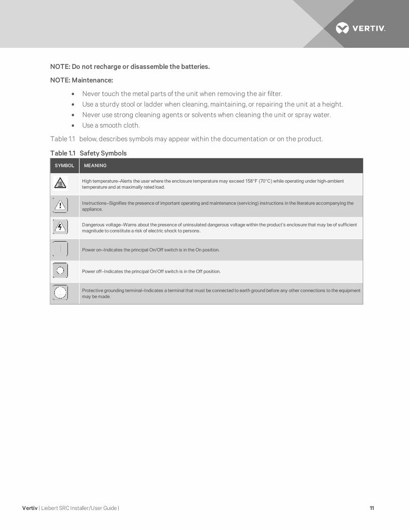
Table 1.1 below, describes symbols may appear within the documentation or on the product.
SYMBOL MEANING
High temperature—Alerts the user where the enclosure temperaturemay exceed 158°F (70°C) while operating under high-ambienttemperature and at maximally rated load.
Instructions—Signifies the presence of important operating andmaintenance (servicing) instructions in the literature accompanying theappliance.
Dangerous voltage—Warns about the presence of uninsulated dangerous voltage within the product’s enclosure that may be of sufficientmagnitude to constitute a risk of electric shock to persons.
Power on—Indicates the principal On/Off switch is in the On position.
Power off—Indicates the principal On/Off switch is in the Off position.
Protective grounding terminal—Indicates a terminal that must be connected to earth ground before any other connections to the equipmentmay bemade.
Table 1.1 Safety Symbols
Vertiv | Liebert SRC Installer/User Guide | 11

Vertiv | Liebert SRC Installer/User Guide | 12
This page intentionally left blank.
2 MODEL NUMBER NOMENCLATUREThis section describes the model-number configuration for Liebert SRC units and components.
2.1 Model-number Nomenclature Detail
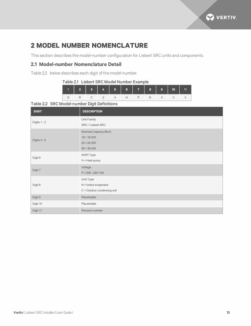
Table 2.2 below describes each digit of the model number.
1 2 3 4 5 6 7 8 9 10 11
S R C 2 4 H P N 0 0 0
Table 2.1 Liebert SRCModel Number Example
DIGIT DESCRIPTION
Digits 1 - 3Unit Family
SRC =Liebert SRC
Digits 4 - 5
Nominal Capacity Btu/h
18 = 18,000
24 =24,000
36 =36,000
Digit 6AHRI Type
H =Heat pump
Digit 7Voltage
P =208 - 230/1/60
Digit 8
Unit Type
N = Indoor evaporator
C =Outdoor condensing unit
Digit 9 Placeholder
Digit 10 Placeholder
Digit 11 Revision number
Table 2.2 SRCModel-number Digit Definitions
Vertiv | Liebert SRC Installer/User Guide | 13

Vertiv | Liebert SRC Installer/User Guide | 14
This page intentionally left blank.

3 PRODUCT INTRODUCTIONSuggestions for Energy Saving when Operating the Liebert SRC:
• Do not cool excessively indoors. This may be harmful for your health and may consume moreelectricity.
• Block sunlight with blinds or curtains while you are operating the unit.
• Keep doors or windows closed tightly while you are operating the unit.
• Adjust the direction of the air flow vertically or horizontally to circulate indoor air.
• Speed up the fan to cool or warm indoor air quickly, within a short period of time.
• Open windows regularly for ventilation. The indoor air quality may deteriorate if the unit is usedfor long durations.
• Clean the air filter once every 2 weeks. Dust and impurities collected in the air filter may blockthe air flow or weaken the cooling / dehumidifying functions.
Figure 3.1 Indoor Unit Parts and Functions
ITEM DESCRIPTION ITEM DESCRIPTION
1 Air filter (under the panel) 5 Air deflector (vertical louver)
2 Air intake 6 Air deflector (horizontal vane)
3 Front cover 7 Air outlet
4 On/Off button
Vertiv | Liebert SRC Installer/User Guide | 15

NOTE: The number and location of operation lamps may vary by unit model. The features may vary bymodel.
Figure 3.2 Outdoor Unit Parts and Functions
ITEM DESCRIPTION
1 Air intake vents
2 Air outlet vents
Vertiv | Liebert SRC Installer/User Guide | 16

NOTE: Some functions may not be available or displayed depending on unit type.
Figure 3.3 Thermostat parts and functions
ITEM DESCRIPTION ITEM DESCRIPTION
1 Operation indication 10 Air-flow button
2 Set temperature button 11 Cooling temperature setpoint
3 Fan speed button 12 Function setting button
4 Set back button 13 Up, down, left and right buttons
5 Operation-mode select button 14 On/Off button
6Wireless thermostat receiver(not included on somemodels)
15 Heating temperature setpoint
7 Sub function button 16 Set/Cancel button
8 Ventilation button 17 Exit button
9 Reservation button
Figure 3.4 Accessories
ITEM DESCRIPTION ITEM DESCRIPTION
1 Connection cable, 1 each, 32 ft (10 m) 3 User Manual
2 Screw, 4 each
Vertiv | Liebert SRC Installer/User Guide | 17

NOTE: Some options and functions may not be displayed or the menu name may be differentdepending on your system and model.
Figure 3.5 Icon descriptions and functions
ITEM SECTION ICON DESCRIPTION
1 OperatingMode
Auto—change to cooling or heatingmode automatically.
Operating in coolingmode.
Operating in dehumidificationmode.
Operating in heatingmode.
Operating in fan-only mode.
Table 3.1 Icon Descriptions
Vertiv | Liebert SRC Installer/User Guide | 18

ITEM SECTION ICON DESCRIPTION
2 Sub functions
Plasma purification filter is operating.
Energy-saving coolingmode, operating in limitedtemperature range.
Automatic drying is operating.
Electric heater is operating in heater mode.
Humidifier is operating.
Automatic fan function on indoor unit.The fan doesn’t operate in the indoor unit when thecompressor is off.
3 Temperature
Current temperature.
Cooling temperature setpoint.
Heating temperature setpoint.
4 Fan Speed Fan-speed settings.
5 Air-flow/Louvers
Swing louvers up/down.
Swing louvers left/right.
Swing louvers for “swirl” (paired, opened cross swing).
6 Controller Modes
Operate in schedulemode.
Temporarily operate in amode.
Override schedule (occupied/unoccupied).
Operate in set-back mode.
Table 3.1 Icon Descriptions (continued)
Vertiv | Liebert SRC Installer/User Guide | 19

ITEM SECTION ICON DESCRIPTION
7 StateMonitoring
Command received from central controller or outdoorunit.
Slave indoor unit to a heat-pump system.Prevents changing to amode that is incompatible withthe current mode of the outdoor unit.
Outdoor unit is operating.
Indoor unit is pre-heating.
Defrost is operating.
Function is not applied.
8 Schedule
Simple schedule is in use.
Sleep schedule is in use.
Weekly schedule is in use.
Holiday schedule is in use.
9 Schedule Set-up
Day of Week:
SUN =Sunday
MON =Monday
TUE =Tuesday
WED =Wednesday
THU =Thursday
FRI =Friday
SAT =Saturday
Number of the weekly-schedule event.
Schedule time AM/PM.
Schedule time hour/minute.
min. =minute.
hr. = hour.
Weekly schedule occupied/un-occupied state.
Copy/Paste schedule data.
Table 3.1 Icon Descriptions (continued)
Vertiv | Liebert SRC Installer/User Guide | 20

ITEM SECTION ICON DESCRIPTION
10 Function Settings
Louver set-up.
1, 2, 3, 4, All = louver number.
STD = standard louver angle setting.
Angle of the louver.
Elevation grill set-up.
Grill up.
Grill closed.
Grill down.
Display lock set-up
Display is locked.
Display is not locked.
Set-upminimum-difference value between cooling andheating setpoints.
Set current time.
Set timer for schedule override.
Set-up default setback for cooling/heating temperaturesetpoints.
Clear the air-filter cleaning alarm.
Check the indoor-unit air filter and clean if necessary.
Table 3.1 Icon Descriptions (continued)
3.1 Electrical Data
MODELNOM.TONS
COMPRESSORQTY.
COMPRESSOR (A)COOL/HEAT
FANQTY.
ODU FAN(A)
IDU FAN(A)
MCA(A)
MOP(A)
SRC18 1-1/2 1 14.6/14.6 1 0.25 0.40 19 25
SRC24 1-3/4 1 17.3/17.3 1 0.25 0.5 23 35
SRC36 2-3/4 1 17.3/17.3 1 0.25 0.5 23 35
Table 3.2 Unit Electrical Data
Vertiv | Liebert SRC Installer/User Guide | 21

3.2 R-410A Refrigerant
R-410A refrigerant has a higher operating pressure in comparison to R22 refrigerant and, therefore, allpiping-system materials installed must have a higher resisting pressure that the materials traditionallyused in R22 systems.
R-410A refrigerant is an azeotrop of R32 and R125, mixed at 50:50, so the ozone depletion potential (ODP)is zero. Many countries have approved-of and encouraged R-410A for use as an alternate refrigerant.
WARNING! Risk of piping ruptures and refrigerant leaks. Can cause equipment damage, illness,serious injury and death from suffocation. Do not use piping that is not approved for use inhigh-pressure refrigerant systems. Refrigerant leaks in non-ventilated spaces could causeoxygen depletion levels that are dangerous to discharging and charging.
NOTE: Piping wall thickness must comply with the applicable local, state, and federal codes for the551-psi design pressure of R-410A. Because R-410A is a combination of R32 and R125, the requiredadditional refrigerant must be charged in its liquid state. If the refrigerant is charged in its gaseousstate, its composition changes and the system will not work properly.
Vertiv | Liebert SRC Installer/User Guide | 22

4 PRE-INSTALLATION PREPARATION AND GUIDELINESNOTE: Before installing unit, determine whether any building alterations are required to run piping,wiring and duct work.
4.1 Selecting the Location for the Outdoor Unit
WARNING! Risk of improper installation. Can cause serious injury or death. To avoid thepossibility of fire, do not install the unit in an area where combustible gas may generate, flow,stagnate, or leak. Do not install the unit in a location where acidic solution and spray (sulfur) areoften used. Do not use the unit in environments where oil, steam, or sulfuric gas are present.
NOTICE
Risk of unauthorized access to the unit. Can cause equipment malfunction or damage.
Install a fence to prevent vermin from crawling into the unit or unauthorized individuals fromaccessing it.
Select a location for installing the outdoor unit that will meet the following conditions:
• Where the unit will not be subjected to direct thermal radiation from other heat sources.
• Where operating sound from the unit will not disturb inhabitants of surroundingbuildings.
• Where the unit will not be exposed to direct, strong winds.
• Where there is enough strength to bear the weight of the unit.
• Include space for drainage to ensure condensate flows properly out of the unit when it isin heating mode.
• Include enough space for air flow and for service access.
To ensure that the outdoor unit operates properly, certain measures are required in locations where thereis a possibility of heavy snowfall or severe wind chill or cold.
1. Prepare for severe winter wind chills and heavy snowfall, even in areas of the country wherethese are unusual phenomena.
2. Position the outdoor unit so that its airflow fans are not buried by direct, heave snowfall. If snowpiles up and blocks the airflow, the system may malfunction.
3. Remove any snow that has accumulated 3-15/16 inches or more on the top of the outdoor unit.
4. Place the outdoor unit on a raised platform at least 19-11/16 inches higher than the averageannual snowfall for the area. In environments where there is a possibility of heavy snow, theframe height must be more than 2 times the amount of average annual snowfall, and shouldnot exceed the width of the outdoor unit. If the frame width is wider than the outdoor unit, snowmay accumulate.
5. Install a snow-protection hood.
Vertiv | Liebert SRC Installer/User Guide | 23

6. To prevent snow and heavy rain from entering the outdoor unit, install the suction anddischarge ducts facing away from direct winds.
7. Additionally, the following conditions should be taken into consideration when the unitoperates in defrost mode:
• If the outdoor unit is installed in a highly-humid environment (near an ocean, lake, etc.),ensure that the site is well-ventilated and has a lot of natural light. (For example: Install ona rooftop.)
• Sidewalks or parking lots near the outdoor unit may accumulate moisture after unitoperates in defrost mode that can turn into ice.
Installation location of the outdoor unit can affect indoor-unit operation. The indoor unit may take longerto provide heat, or heating performance will be reduced in winter in the outdoor unit is installed:
• In a narrow, shady location.
• Near a location that has a lot of ground moisture.
• In a highly-humid environment.
• In an area in which condensate does not drain properly.
4.1.1 Ambient-air Conditions
NOTICE
Risk of exposure to improper environmental conditions. Can cause equipment damage.
• Avoid exposing the outdoor unit to steam, combustible gases, or other corrosive elements.
• Avoid exposing the unit to discharge from boiler stacks, chimneys, steam relief ports,other air-conditioning units, kitchen vents, plumbing vents, or substances that maydegrade performance or cause damage to the unit.
• When installing multiple outdoor units, avoid placing the units where discharge of oneoutdoor unit will blow into the inlet side of an adjacent unit.
4.1.2 Oceanside Applications
Using a Windbreak to Shield the Unit from Sea Wind
NOTE: Ocean winds may cause corrosion, particularly on the condenser and evaporator fins, which, inturn could cause product malfunction or inefficient performance.
• Avoid installing the unit where it would be directly exposed to ocean winds.
• Install the outdoor unit on the side of the building opposite from direct ocean winds.
• Select a location with good drainage.
• Periodically clean dust or salt particles off of the heat exchanger with water.
• If the outdoor unit must be placed in a location where it would be subjected to direct oceanwinds, install a concrete windbreak strong enough to block any winds, see Figure 4.1 on thefacing page for windbreak location.
• The windbreak should be more than 150% of the outdoor unit’s height. There must be 2 to 3-1/2inches of clearance between the outdoor unit and the windbreak for purposes of flow.
Vertiv | Liebert SRC Installer/User Guide | 24

Figure 4.1 Oceanside placement using a windbreak
ITEM DESCRIPTION
1 Windbreak
2 Sea wind
Vertiv | Liebert SRC Installer/User Guide | 25

Using a Building to Shield the Unit from Sea Wind
If a windbreak is not possible, a building or larger structure must be used to shield the outdoor unit fromdirect exposure to the sea wind. The unit should be placed on the side of the building directly opposite tothe direction of the wind as shown in Figure 4.2 below.
Figure 4.2 Oceanside placement using a building
ITEM DESCRIPTION
1 Building
2 Sea wind
4.2 Clearance Requirements
Proper airflow through the outdoor unit coil is critical for correct unit operation. When installing, considerservice, inlet and outlet, and minimum allowable space requirements as illustrated in Figure 4.3 on thefacing page.
Vertiv | Liebert SRC Installer/User Guide | 26

4.2.1 Outdoor Unit Clearance
Specific clearance requirements are for the wall-mount systems. Figure 4.3 below shows the overallminimum clearances that must be observed for safe operation and adequate airflow around the outdoorunit.
Figure 4.3 Outdoor-unit clearances
ITEM DESCRIPTION ITEM DESCRIPTION
1 More than 24 inches. 4 More than 28 inches.
2 More than 12 inches. 5 More than 12 inches.
3 More than 24 inches.
When placing the outdoor unit under an overhang, awning, sunroof or other “roof-like” structure, observethe clearance requirements (as shown in Figure 4.4 on the next page) for height in relation to the unit.This clearance ensures that heat radiation from the condenser is not restricted around the unit. SeeFigure 4.5 on the next page and Figure 4.6 on page 29 for recommendations when other obstacles arepresent.
Adhere to all clearance requirements if installing the unit on a roof. Be sure to level the unit and ensurethat the unit is adequately anchored. Consult local codes for roof-top mounting requirements.
NOTE: Do not place the unit where animals and/or plants will be in the path of the warm air, or wherethe warm air and/or noise will disturb neighbors.
Vertiv | Liebert SRC Installer/User Guide | 27

Figure 4.4 Outdoor-unit sunroof/awning clearances
ITEM DESCRIPTION
1 More than 12 inches.
2 More than 24 inches.
3 More than 28 inches.
Figure 4.5 Clearances when there are obstacles on both air-inlet and air-outlet sides
ITEM DESCRIPTION
1 More than 28 inches.
2 More than 12 inches.
NOTE: In Figure 4.5 above and Figure 4.6 on the facing page, the obstacle on the outlet side is lowerthan the outdoor unit.
Vertiv | Liebert SRC Installer/User Guide | 28

Figure 4.6 Clearances when there are obstacles above and on both air-inlet and air-outlet sides
ITEM DESCRIPTION ITEM DESCRIPTION
1 More than 28 inches. 3 79 inches
2 24 inches 4 More than 12 inches.
4.2.2 Indoor Unit Clearance
Follow recommended practices when choosing an indoor location for the wall-mounted indoor unit.
• Keep unit away from any indoor steam or excessive heat.
• No obstacles should be placed around the unit.
• Condensation drain (leakage piping) should be routed away from the unit.
• Do not install near a doorway.
• Clearance gap between any wall or enclosure and the left or right side of the unit must begreater than 4 inches, Figure 4.7 on the next page.
• From the top of the unit to the ceiling, there must be greater 8 inches of clearance, see Figure4.7 on the next page.
• Unit should be at least 6.5 feet from the floor for adequate clearance.
Vertiv | Liebert SRC Installer/User Guide | 29

Figure 4.7 Indoor unit clearance requirements
ITEM DESCRIPTION ITEM DESCRIPTION
1 More than 4 inches. 3 More than 4 inches.
2 Minimum clearance from ceiling - 6 in. 4 At lease 6.5 feet from floor.
Vertiv | Liebert SRC Installer/User Guide | 30

5 INSTALLATION5.1 Mounting the Outdoor Unit
Securely attach the outdoor unit to a condenser pad, base rails, or another mounting platform that issecurely anchored to the ground or building structure. Attach the outdoor unit with a bolt and nut on aconcrete or rigid mount. See Figure 5.1 below. Follow applicable local codes for clearance, mounting,anchor and vibrations attenuation requirements.
NOTE: All referenced materials are field-supplied. Images are not to scale.
Figure 5.1 Outdoor unit mounting methods
ITEM DESCRIPTION ITEM DESCRIPTION
1 Bolt placement and Anti-vibration pad 3 Piping connection
2 Foundation 4 Top of unit
5.1.1 Mounting-platform Guidelines
The underlying structure or foundation must be designed to support the weight of the unit. Avoid placingthe unit in a low-lying area where water may accumulate. When installing the outdoor unit on the wall orroof top, anchor the mounting base securely to account for wind, earthquake or vibration.
Vertiv | Liebert SRC Installer/User Guide | 31

5.1.2 Tie-down and Wind-restraint Guidelines
The strength of the inverter system frame is adequate to be used with field-provided wind restraint tie-downs. The overall tie-down configuration must be approved by a local, professional engineer.
NOTE: Always refer to local code when designing a wind-restraint system.
5.1.3 Considerations for Snow and Ice Conditions
In climates that experience snow build-up, place the unit on a raised platform to ensure condenser airflow. The raised support platform must be high enough to allow the unit to remain above possible snowdrifts. Mount the unit on a field-provided snow stand at a minimum height that is equal to the averageannual snowfall plus 20 inches. Design the mount base to prevent snow accumulation on the platform infront or back of the unit case. If necessary, provide a field fabricated hood to keep snow and ice and/ordrifting snow from accumulating on the coil surfaces. Use inlet and discharge duct or hoods to preventsnow or rain from accumulating on the fan inlet and outlet guards. Best practice prevents snow fromaccumulating on top of the unit. Consider the tie-down requirements in case of high winds or whererequired by local codes.
CAUTION: Risk of run-off water freezing on sidewalks and driveways. Can cause falls andinjuries. When selecting the location for the outdoor unit, be sure to choose an area where run-off from defrost will not accumulate and freeze on sidewalks or driveways.
5.2 Installing a Wind Baffle on the Outdoor Unit
A wind baffle allows cooling-mode operation at lower ambient outdoor temperatures.
Read all instructions before installing wind baffles.
CAUTION: Risk of contact with sharp edges and exposed fasteners. Can cause injury. Wearappropriate, OSHA-approved personal protective equipment (PPE) when installing thecomponent.
5.2.1 Precautions for Wind Baffle Installation
Consider the following when installing the wind baffle:
• Be sure not to damage the painted surface.
• Carefully drill holes so that no damage occurs to external or internal parts of the unit.
• Make sure that drill chips do not enter the unit.
5.2.2 Wind-baffle Assembly Inspection and Installation
1. Inspect all items for visible or concealed damage. Immediately report any damage to the carrierand file a damage claim, sending a copy of the claim to your local sales representative.
2. Remove items from packaging and refer to Table 5.1 on the facing page to verify that theassembly number is correct by SRC model to which it will be installed and that all parts arepresent.
Vertiv | Liebert SRC Installer/User Guide | 32

WIND-BAFFLEPART NUMBER
COMPATIBLEOUTDOOR UNIT
SELF-TAPPINGSCREWTYPE
SELF-TAPPING SCREWQUANTITY
BAFFLE DIMENSIONS(W X H X D),IN. (MM)
327135P1 SRC18
#8 x 1/2 in.
619-11/16 x 19-11/16 x 7-15/16
(500 x 500 x 202)
327135P2SRC24
823-5/8 x 23-5/8 x 7-15/16
(600 x 600 x 202)SRC36
Table 5.1 Wind-baffle assembly numbers, kit parts, and dimension
3. Referring to Figure 5.2 below, center the baffle both vertically and horizontally over the fancover. Make sure that the baffle does not cover the access panel.
Figure 5.2 Wind-baffle installation
ITEM DESCRIPTION ITEM DESCRIPTION
1 327135P1 (for SRC18) 2 327135P2 (for SRC24, SRC36)
4. Using the drill, mark the screw-hole positions.
5. Using the provided screws, connect the baffle flanges to the unit at the marked holes. Do notover-tighten the screws.
6. Once the baffle is secure, check to see if the unit and baffle are working properly.
Vertiv | Liebert SRC Installer/User Guide | 33

5.3 Installing the Indoor Unit
5.3.1 Mounting the Installation Plate to the Wall (SRC18)
WARNING! Risk of electric shock. Can cause equipment damage, injury or death. Open all localand remote electric power supply disconnect switches and verify with a voltmeter that power isoff before working within any electric connection enclosures. Service and maintenance workmust be performed only by properly trained and qualified personnel and in accordance withapplicable regulations and manufacturers’ specifications. Opening or removing the covers toany equipment may expose personnel to lethal voltages within the unit even when it isapparently not operating and the input wiring is disconnected from the electrical source.
WARNING! Risk of improper installation. Can cause equipment and building damage, injury ordeath. Utilize a structural engineer to evaluate the mounting surface and environmental risksand recommend the safest fastening method.
Observe the following guidelines when installing the mounting plate:
• When choosing a location for the wall-mount plate, be sure to take into consideration routing ofwiring for power outlets within the wall.
• Use caution when drilling holes through the walls for the purposes of piping connections.
• Refer to Drilling a Piping Hole in the Wall on page 38, as you follow the plate-installationprocedure.
• Unit must be anchored tightly to a wall that has sufficient strength to support the unit duringoperation to prevent the unit from falling or creating excessive, unnecessary vibration duringoperation.
• Use best practices when mounting the indoor unit’s plate to a wall.
To install the indoor unit:
1. Before installation of the plate, confirm the position of the screw types (A or B) between thechassis and the installation plate, Figure 5.3 on the facing page.
Vertiv | Liebert SRC Installer/User Guide | 34

Figure 5.3 Installation-plate screws for SRC18
ITEM DESCRIPTION
1 A-Type
2 B-Type
Vertiv | Liebert SRC Installer/User Guide | 35

2. Depending on indoor-unit model refer to Figure 5.4 below and mount the plate as follows:
• Use the provided screws and mount the installation plate horizontally by aligning thecenterline using a leveling tool.
• Observe the left and right rear piping clearance when drilling into the wall.
Figure 5.4 Piping clearance for SRC18 plate
ITEM DESCRIPTION ITEM DESCRIPTION
1 Unit outline. 5 Installation-plate measuring tape.
2 Place a level on raised tabs. 6 Measuring tape hanger.
3 Right rear piping. 7 Left rear piping.
4 Units = Inches
5.3.2 Mounting the Installation Plate to the Wall (SRC24 and SRC36)
WARNING! Risk of electric shock. Can cause equipment damage, injury or death. Open all localand remote electric power supply disconnect switches and verify with a voltmeter that power isoff before working within any electric connection enclosures. Service and maintenance workmust be performed only by properly trained and qualified personnel and in accordance withapplicable regulations and manufacturers’ specifications. Opening or removing the covers toany equipment may expose personnel to lethal voltages within the unit even when it isapparently not operating and the input wiring is disconnected from the electrical source.
WARNING! Risk of improper installation. Can cause equipment and building damage, injury ordeath. Utilize a structural engineer to evaluate the mounting surface and environmental risksand recommend the safest fastening method.
Vertiv | Liebert SRC Installer/User Guide | 36

Observe the following guidelines when installing the mounting plate:
• When choosing a location for the wall-mount plate, be sure to take into consideration routing ofwiring for power outlets within the wall.
• Use caution when drilling holes through the walls for the purposes of piping connections.
• Refer to Figure 5.5 below, as you follow the plate-installation procedure.
• Unit must be anchored tightly to a wall that has sufficient strength to support the unit duringoperation to prevent the unit from falling or creating excessive, unnecessary vibration duringoperation.
• Use best practices when mounting the indoor unit’s plate to a wall.
To install the indoor unit:
1. Use the provided screws, mount the installation plate horizontally by aligning the centerlineusing a leveling tool, Figure 5.5 below.
Figure 5.5 Installation-plate screws for SRC24 and SRC36
ITEM DESCRIPTION
1 Chassis hook.
2 Type “A” screws.
2. Observe the left and right rear piping clearance when drilling into the wall, Figure 5.6 on thenext page.
Vertiv | Liebert SRC Installer/User Guide | 37

Figure 5.6 Piping clearance for SRC24 and SRC36
ITEM DESCRIPTION
1 Left rear piping.
2 Unit = inches.
3 Right rear piping.
5.3.3 Drilling a Piping Hole in the Wall
Follow the left or right piping-clearance recommendations.
1. Using a 2-5/8 in. (0.65 mm) hole-core drill bits, drill a hole at either the right or left side of thewall mounting, Figure 5.7 on the facing page.
• The slant of the hole should be 3/16 to 5/16 of an inch from level with an upward slant onthe indoor-unit side and downward on the outdoor-unit side.
2. Finish-off the newly-drilled hole as shown in Figure 5.7 on the facing page with a bushing andsleeve covering.
• The sleeve and bushing prevents damage to the tubing/bundling of the piping.
Vertiv | Liebert SRC Installer/User Guide | 38

Figure 5.7 Drilling a piping hole
ITEM DESCRIPTION ITEM DESCRIPTION
1 Wall 4 Sleeve
2 Indoor 5 Bushing
3 Outdoor 6 Core Drill
5.3.4 Installing the Optional Condensate Pump
The optional, field-installed condensate pump may be located inside or outside the evaporator section ofthe SRC, below the bottom of the drain pain.
The pump consist of 2 parts, the reservoir and the control unit/pump.
Figure 5.8 Condensate-pump reservoir
ITEM DESCRIPTION ITEM DESCRIPTION
1 Float 4 Intake tube
2 Vent tube 5 Water-collecting reservoir
3 Reservoir cable 6 Water drain
Vertiv | Liebert SRC Installer/User Guide | 39

Figure 5.9 Condensate-pump control unit/pump
ITEM DESCRIPTION ITEM DESCRIPTION
1 Reservoir cable 5 Hose clamp on end of discharge tube
2 Screw cover 6 Discharge tube
3 Hose clampe 7 Direction of flow
4 Pump 8 Intake tube
To install the pump:
1. Verify that the drain pan is fee of debris.
2. Referring to Figure 5.10 below and supporting the reservoir, attach the discharge tube fromthe drain pan to the reservoir and be sure that the tubing does not kink.
NOTE: For clarity, the refrigerant piping lines are removed from Figure 5.10 below.
Figure 5.10 Condensate pump connection to drain pan
ITEM DESCRIPTION ITEM DESCRIPTION
1 Vinyl discharge tube connection to reservoir inlet. 2 Rear of unit
3 Drain-pan connection
Vertiv | Liebert SRC Installer/User Guide | 40

3. Connect the breather tube to the reservoir outlet marked “VENT,” and be sure that the tubingdoes not kink.
4. Place the reservoir in the rear of the evaporator unit as shown in Figure 5.11 below.
• The reservoir must be level within ±15 degrees. Performance is optimum when thereservoir is level.
NOTE: If the reservoir is mounted improperly, the float mechanism maymalfunction and may cause theunit to overflow.
Figure 5.11 Condensate pump location below drain pan
ITEM DESCRIPTION ITEM DESCRIPTION
1 Drain-pan connection 2 Discharge condensate into drain
5. Using the provided Ty-Rap, mount the control unit/pump.
NOTE: The control unit/pump is not submersible. Install the control unit/pump so that water cannotdrip, splash or spray onto it. Do not install the control unit/pump more than 3 ft (1 m) higher (vertically)than the collection reservoir.
6. Using the provided hose clamps, connect the tubing to from the outlet of the reservoir marked“PUMP” to the inlet of the pump (indicated by the directional arrow on the side of the pump).
7. Using a field-supplied hose clamp, attach a 5/32-in. ID tube to the discharge of the pump, anddirect the other end of the discharge tubing to a gravity-feed drain.
NOTE: The maximum horizontal run is 60 ft (18 m), which results in a drop in flow rate of 10 to 15%.
NOTE: The end of the discharge tubing that is directed into the gravity-feed drain must be no morethan 3 ft (1 m) below the collection reservoir. Locating the end further below creates a siphoning effectthat results in noisy operation and shortens the life of the pump.
Vertiv | Liebert SRC Installer/User Guide | 41

8. Connect the 4-prong plug connector cable from the reservoir into the corresponding socketon top of the to the control unit/pump, Figure 5.12 below.
Figure 5.12 Cable-connection socket on control unit/pump
9. Referring to Table 5.2 below and Figure 5.13 on the facing page, connect the condensatepump power supply:
• Prepare the power-supply leads by stripping approximately 1/4-in. of the lead wireinsulation jacket.
• On the terminal block, remove the screw cover to expose the set screws and confirm thatthe lead-wire slots are open, that is: set screws turned counterclockwise.
• Identify the line, neutral and ground power-supply leads from the power supply.
WIRE COLOR CONNECTS TO:
Blue orWhite (neutral) N
Brown or Black (line) L
Green/Yellow or Green (ground) ground
Table 5.2 Power-supply to Control Unit Wiring
• Refer to the label on the control unit/pump to identify the correct terminal locations foreach power-supply lead, and insert the correct lead completely into the correspondingslot of the terminal block.
• Tighten the set screw, turning clockwise, to secure the power-supply leads in place in theterminal block.
• Fit a field-supplied, 0.20-A fuse in the line lead of the cable that supplies the controlunit/pump.
• Connect L1, L2, and Ground from the control unit/pump to the evaporator terminal block,Figure 5.13 on the facing page.
Vertiv | Liebert SRC Installer/User Guide | 42

Figure 5.13 Power-supply wiring for the condensate pump
ITEM DESCRIPTION ITEM DESCRIPTION
1 Butt splice 4 Power feed to outdoor unit
2 Indoor-unit terminal block 5 In-line fuse
3 Outdoor-unit terminal block
5.3.5 Mounting the Indoor Unit to the Plate
1. Hook the indoor unit onto the upper portion of the installation plate, Figure 5.14 on the nextpage.
2. Engage the hooks at the top of the indoor unit with the upper edge of the installation plates.
• Make sure that the hooks are properly seated on the installation plate by moving the unitleft and right.
Vertiv | Liebert SRC Installer/User Guide | 43

Figure 5.14 Hook the top of the unit to the plate
ITEM DESCRIPTION ITEM DESCRIPTION
1 Hook to top of installation plate. 4 Indoor unit.
2 Move bottom of unit to install plate. 5 Spacer.
3 Installation plate.
3. Move the bottom of the unit toward the installation plate to anchor to wall, Figure 5.15 below.
• It helps to press the lower-left and -right sides of the unit against the installation plateuntil the hooks engage in their slots.
• You will hear a clicking sound as the bottom attaches to the installation plate.
Figure 5.15 Move the bottom of the unit to the plate and attach to plate
ITEM DESCRIPTION
1 Drain-hose holder L-bracket
2 Installation plate.
Vertiv | Liebert SRC Installer/User Guide | 44

4. Finish by inserting 2 type “C” screws into the bottom of the installation plate, Figure 5.16 below.
• As you insert the screws, pay attention to the position of the piping through any wall, asshown in the figure.
Figure 5.16 Insert and tighten screws
ITEM DESCRIPTION ITEM DESCRIPTION
1 Piping through wall. 3 Type “C” screws.
2 Indoor unit. 4 Bottom of indoor unit.
5.3.6 Prepare for Piping/Electrical Connection
1. To prepare the indoor unit for piping, disengage the bottom on the indoor unit from theinstallation plate by reversing 3 of Mounting the Indoor Unit to the Plate on page 43.
• This separates the bottom of the indoor unit from the wall mount so you can route thedrain hose correctly. Figure 5.17 on the next page shows the rear view of the indoor unit.
2. Swing the drain-hose holder (L-bracket) out and anchor as show in Figure 5.15 on theprevious page.
3. Refer to Piping Requirements on page 51, to continue with the piping connections to theindoor unit.
– or –
Refer to Electrical Connections on page 89, to continue with the conduit/electrical wiring tothe indoor unit.
Vertiv | Liebert SRC Installer/User Guide | 45

Figure 5.17 Rear view of indoor unit
ITEM DESCRIPTION
1 Installation plate
2 Drain hose
3 Drain-hose holder
5.4 Pump Down Procedure
CAUTION: Risk of inhalation of refrigerant gas. Can cause illness and injury. Never air purgewith refrigerant as it can cause refrigerant leakage.
NOTE: Use a vacuum pump that can evacuate down to 500microns.
1. If moisture remains in the piping after the system is evacuated for 2 hours, break the vacuum(down to 7.5 psi with nitrogen gas).
2. Evacuate the system again with the vacuum pump for at least 1 hour to 500 microns.
3. If the system does not reach 500 microns within 2 hours, repeat the vacuum break andevacuation procedure until the gauge does not rise.
This procedure is performed when a unit must be relocated or the refrigerant circuit is serviced. “Pumpingdown” is a term that means collecting all refrigerant into the outdoor unit without the loss of anyrefrigerant. Use the following procedure to safely collect refrigerant back into the outdoor unit. Alwaysadhere to and be familiar with local codes regarding the handling of refrigerant.
The system must be placed in Cooling mode to proceed with the pump-down procedure. Refer toEnabling Cooling-only Mode on page 110, for the steps.
CAUTION: Risk of exposure or contact with refrigerant. Can cause injury and illness.Refrigerant is toxic and too cold for safe human contact. Do not inhale or handle refrigerantdirectly.
Vertiv | Liebert SRC Installer/User Guide | 46

NOTE: Perform pump-down procedure only in cooling mode.
To perform pump down:
1. Connect a low-pressure gauge with manifold hose to the charge port on the gas-line servicevalve.
2. Open the gas-line service valve half-way.
3. Purge the air in the manifold hose using the refrigerant.
4. Close the liquid line service valve completely.
5. Turn on the cooling-unit’s power switch and start cooling-mode operation, Enabling Cooling-only Mode on page 110.
6. Observe the pressure gauge reading.
• When the gauge reads 1 to 0.5 kg/cm2 (14.2 to 7.1 psig), fully-close the gas-line valve andimmediately turn of the cooling unit.
Pump-down is complete, and all refrigerant should be collected into the outdoor unit.
Vertiv | Liebert SRC Installer/User Guide | 47

Vertiv | Liebert SRC Installer/User Guide | 48
This page intentionally left blank.

6 INSTALLATION CHECKLISTMajor Component Rough-in
1. Unit was connected properly per local code and the product installation procedures.
2. All literature and bagged accessories have been removed from the fan discharge.
3. Indoor unit was installed, properly supported, and located indoors in a non-corrosiveenvironment.
4. Unit’s gravity condensate drain line was connected and routed where it properly drains awayor, if installed in a mechanical room, was connected and properly routed to a drain terminal.
Piping and Insulation
1. Copper
2. Over 5/8 inches—Rigid ACR only
3. 5/8 inches and under—can use soft ACR.
4. 15% silver brazing material only.
5. All refrigerant pipes and valves were insulated separately. Insulation butts up against the wallsof the indoor units. No gaps or cracks. Insulation was not compressed at clamps and hangers.
Brazing Practices
1. Medical grade (there are 4 available) dry nitrogen for purging during brazing was used(constant 3 psi while brazing).
Installation
Refer to the details in the Installation section for more information on any procedure.
Refrigerant Piping
1. All pipe materials were properly stored, capped, and clean. All burrs were removed after cuttingand pipe ends were reamed before brazing.
2. During refrigerant pipe installation, for each segment of pipe, a record was made of the pipelength (including expansion loops, offsets, double-back sections), and sizes, as well as thequantity and type of elbows used.
3. All long runs of straight pipe were provided with expansion loops.
4. A torque wrench and backup wrench were used to tighten all flare connections.
5. The back side of all flares were lubricated with a small drop of PVE refrigeration oil beforetightening flare fittings.
6. Ensure all field-made flares are 45°. Used factory-suppled flare nuts only.
7. Pipe segments were properly supported and all wall penetrations were sleeved.
8. Pipe insulation was not compressed at any point.
9. No oil traps, solenoid valves, sight glasses, filter driers, or any other unauthorized refrigerantspecialties were present.
10. Best practice including a minimum of 20-inch straight pipe was installed between each elbow.
Vertiv | Liebert SRC Installer/User Guide | 49

PowerWire and Communication Cables
1. Power wiring was connected to a single-phase 208 – 230-V source.
2. Ground wire was installed and properly terminated at the unit.
3. The power supplied was clean with voltage fluctuations with specifications. (±10% ofnameplate).
4. Power wiring to the outdoor unit was installed per all local electrical code requirements.
5. Power wiring to the indoor unit was installed per all local electrical code requirements.
6. Factory-supplied cable was used between the indoor unit and the thermostat. No cables werespliced and no wire caps are present.
7. Communication type RS-485-BUS type.
8. All communication cables were a minimum of 18-AWG, 4 conductor, shielded, and stranded,with insulation material per local code. Cable segment shield were tied together.
9. Used appropriate crimping tool to attach ring or spade terminals at all power wiring and controlcable terminations.
10. All power and control wires were properly separated using the recommended distanceprovided in the installation manual.
Vertiv | Liebert SRC Installer/User Guide | 50

7 PIPING REQUIREMENTS
WARNING! Do not allow the refrigerant to leak during brazing. If the refrigerant is combusted, itgenerates a toxic gas that can cause physical injury or death. Do not braze in an enclosedlocation, and always test for gas leaks before/after brazing. After brazing, check for refrigerantgas leaks.
• Do not use kinked pipe cause by excessive bending in one specific area on its length.
• Braze the pipes to the service-valve pipe stem of the outdoor unit.
7.1 Creating a Flare Fitting
WARNING! Risk of refrigerant leaks. Can cause equipment malfunction, injury, sickness anddeath from suffocation due to oxygen depletion in closed, non-ventilated areas. When selectingflare fittings, always use a 45° fitting rated for use with high-pressure refrigerant R410A. Verifythat all fittings comply with local, state, or federal standards.
NOTE: One of the main causes of refrigerant leaks is defective flared connections. Create flaredconnections using the procedure shown in Figure 7.1 on the next page and steps that follow.
Vertiv | Liebert SRC Installer/User Guide | 51

Figure 7.1 Creating a flared fitting
ITEM DESCRIPTION ITEM DESCRIPTION
1 Copper tube 12 Cone
2 Slanted 13 Red Arrow
3 Uneven 14 Clamp handle
4 Rough 15 Copper pipe
5 Pipe 16 Smooth
6 Point down. 17 Inside shiny with no scratches.
7 Reamer 18 Even length.
8 Flare nut 19 Slanted
9 Bar 20 Damaged surface
10 Handle 21 Cracked
11 Yoke 22 Uneven thickness
To create the fitting:
1. Cut the pipe to length.
• Measure the distance between the indoor unit and the outdoor unit.
• Cut the pipes a littler longer than the measured distance.
• Cut the cable 4.9 ft longer than the pipe length.
2. A. Remove the burrs.
• Completely remove all burrs from pipe ends.
• When removing burrs, point the end of the copper pipe down to avoid introducing foreignmaterials into the pipe.
B. Slide the flare nut onto the copper tube.
Vertiv | Liebert SRC Installer/User Guide | 52
3. Flaring the pipe end.
• Use the proper size flaring tool to finish flared connections as shown in Figure 7.1 on theprevious page.
• Always create a 45° flare when working with R410A. Refer to the Warning preceding thisprocedure.
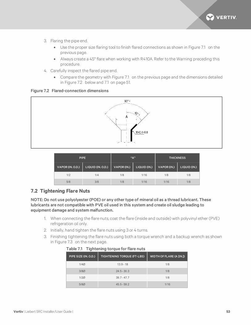
4. Carefully inspect the flared pipe end.
• Compare the geometry with Figure 7.1 on the previous page and the dimensions detailedin Figure 7.2 below and 7.1 on page 51.
Figure 7.2 Flared-connection dimensions
PIPE “A” THICKNESS
VAPOR (IN. O.D.) LIQUID (IN. O.D.) VAPOR (IN.) LIQUID (IN.) VAPOR (IN.) LIQUID (IN.)
1/2 1/4 1/8 1/16 1/8 1/8
5/8 3/8 1/8 1/16 1/16 1/8
7.2 Tightening Flare Nuts
NOTE: Do not use polyolyester (POE) or any other type of mineral oil as a thread lubricant. Theselubricants are not compatible with PVE oil used in this system and create oil sludge leading toequipment damage and system malfunction.
1. When connecting the flare nuts, coat the flare (inside and outside) with polyvinyl ether (PVE)refrigeration oil only.
2. Initially, hand tighten the flare nuts using 3 or 4 turns.
3. Finishing tightening the flare nuts using both a torque wrench and a backup wrench as shownin Figure 7.3 on the next page.
PIPE SIZE (IN. O.D.) TIGHTENING TORQUE (FT-LBS) WIDTHOFFLARE (A [IN.])
1/4Ø 13.9 – 18 1/8
3/8Ø 24.5 – 30.3 1/8
1/2Ø 39.7 – 47.7 1/8
5/8Ø 45.5 – 59.2 1/16
Table 7.1 Tightening torque for flare nuts
Vertiv | Liebert SRC Installer/User Guide | 53

Figure 7.3 Tightening the flare nuts
ITEM DESCRIPTION
1 Union.
7.2.1 Loosening Flare Nuts
Always use 2 wrenches to loosen the flare nuts.
7.3 Piping Materials and Handling
Pipes used for the refrigerant piping system must include the specified thickness, and the interior mustbe clean.
While handling and storing, do not bend or damage the pipes, and take care not to contaminate theinterior with dust, moisture, etc. See Table 7.2 on the facing page for care of piping.
Figure 7.4 Keep piping capped while storing
Vertiv | Liebert SRC Installer/User Guide | 54

DRY CLEAN AIRTIGHT
Principles
Nomoisture should be inside the piping. No dust should be inside the piping. No leaks should occur.
ProblemsCaused
• Significant hydrolysis ofrefrigerant oil.
• Refrigerant oildegradation.
• Poor insulation of thecompressor.
• System does notoperate properly.
• EEVs, capillary tubesare clogged.
• Refrigerant oildegradation.
• Poor insulation of thecompressor.
• System does notoperate properly.
• EEVs and capillarytubes become clogged.
• Refrigerant gasleaks/shortages.
• Refrigerant oildegradation.
• Poor insulation of thecompressor.
• System does notoperate properly.
Solutions
• Removemoisture fromthe piping.
• Piping ends shouldremain capped untilconnections arecomplete.
• Do not install piping on arainy day.
• Connect piping properlyat the unit’s side.
• Remove caps only afterthe piping is cut, theburrs are removed, andafter passing the pipingthrough the walls.
• Evacuate system to aminimum of 500 micronsand ensure the vacuumholds at that level for 24hours.
• Remove dust from thepiping.
• Piping ends shouldremain capped untilconnections arecomplete.
• Connect piping properlyat the side of the unit.
• Remove caps only afterthe piping is cut andburrs are removed.
• Retain the cap on thepiping when passing itthrough walls, etc.
• Test system for air-tightness.
• Perform brazingproc3edures thatcomply with allapplicable standards.
• Perform flaringprocedures thatcomply with allapplicable standards.
• Perform flangingprocedures thatcomply with allapplicable standards.
• Ensure that refrigerantlines are pressure-testto 550 psig.
Table 7.2 Three principles of refrigerant piping
Vertiv | Liebert SRC Installer/User Guide | 55

7.3.1 Brazing Practices
IMPORTANT! It is imperative to keep the piping system free of contaminants and debris such ascopper burrs, slag, or carbon dust during installation. Contaminants can result in mechanical failure ofthe system.
All joints are brazed in the field. Refrigeration-system components contain very small capillary tubes, smallorifices, electronic expansion valves, oil separators, and heat exchangers that can easily become blocked.Proper system operation depends on the installer using best practices and utmost care while assemblingthe piping system.
Figure 7.5 Refrigerant-pipe brazing
ITEM DESCRIPTION ITEM DESCRIPTION
1 Refrigerant piping 4 Pressure-reducing valve
2 Pipe to be brazed 5 Valve
3 Nitrogen 6 Taping
• While brazing, use a dry-nitrogen purge operating at a minimum pressure of 3 psig andmaintain a steady flow.
• Before assembly, use dry nitrogen to blow clean all pipe sections.
• Use a tubing cutter, do not use a saw to cut pipe. De-burr and clean all cuts before assembly.
• Store pipe stock in a dry place. Keep pipe capped and clean.
• Use adapters to assemble different sizes of pipe.
• Do not use flux, soft solder, or anti-oxidant agents.
• Use a 15% silver phosphorous copper-brazing alloy to avoid overheating and produce goodflow.
• Protect isolation valves, electronic expansion valves, and other heat-sensitive controlcomponents from excessive heat with a wet rag or a heat-barrier spray product.
7.3.2 Refrigerant-piping Insulation Guidelines
All refrigerant piping, field-provided isolation ball valves, service valves, and elbows shall be completelyinsulated using closed-cell pipe insulation. The liquid and vapor lines must be insulated separately.
To prevent heat loss/heat gain through the refrigerant5 piping, all refrigerant piping, including liquidlines and vapor lines shall be insulated separately. Insulation shall be a minimum 1/2-in. thick, andthickness may need to be increased based-on ambient conditions and local codes.
Vertiv | Liebert SRC Installer/User Guide | 56

All insulation joints shall be glued with no air gaps. Insulation material shall fit snugly against therefrigeration pip3e with no air space between it and the pipe. Insulation passing through pipe hangers,inside conduit, and/or sleeves must not be compressed. Protects insulation inside handers and supportswith a second layer. All pipe insulation exposed to the sun and outdoor elements shall be properlyprotected with PVC, aluminum vapor barrier, or alternatively placed in a weather-resistant enclosure suchas a pipe rack with a top cover and meet local codes.
The design engineer should perform calculations to determine if the factory-supplied insulation jacketsare sufficient to meet local codes and avoid sweating. Add additional insulation if necessary. Mark all pipesat the pint where the insulation jacket ends. Remove the jacket. Install field-provided insulation on therun-out and main-trunk pipes first. Peel the adhesive glue protector slip from the insulation jacket andinstall the clam-shell jacket over the fitting.
For specific insulation procedures, see Insulating Refrigeration Piping on page 79.
7.3.3 Selecting Field-supplied Copper Tubing
Copper is the only approved refrigerant-pipe material for use with the Liebert SRC, and we recommendseamless phosphorous deoxidized ACR type copper pipe, hard-drawn rigid type “K” or “L,” or annealed-tempered, copper pipe.
• Drawn temper (rigid) ACR copper tubing is available in sizes 3/8 through 2-1/8 inches(ASTM B 280, clean, dry, and capped).
• Annealed temper (soft) ACR copper tubing is available in sizes 1/4 through 2-1/8 inches(ASTM B 280, clean, dry, and capped).
Tube wall thickness should meet local code requirements and be approved for an operating pressure of551 psi. If local code does not specify wall thickness, We suggest using tube thickness per Table 7.3 below.When bending tubing, try to keep the number of bends to a minimum, and use the largest radii possible toreduce the equivalent length of installed pipe. Also, bending radii greater than 10 pipe diameters canminimize pressure drop. Be sure that no traps or sags are present when rolling-out soft copper-tubingcoils.
NOTE: Commercially-available piping often contains dust and other materials. Always blow it clean witha dry, inert gas. Prevent dust, water or other contaminants from entering the piping during installation.Contaminants can cause mechanical failure.
SPECIFICATIONS DESCRIPTIONS
Type Seamless phosphorous deoxidized
Class UNSC12200 DHP
Straight Lengths H58 temper
Coils O60 temper
Table 7.3 ACR copper-tubing material
Vertiv | Liebert SRC Installer/User Guide | 57

SPECIFICATIONS DESCRIPTIONS/MEASUREMENTS
OD (in.) 1/4 3/8 1/2 5/8 3/4 7/8 1-1/8 1-3/8 1-5/8
Material Rigid type “K” or “L” and a soft ACR acceptable Rigid type “K” or “L” only
Min. Bend Radius (in.) .563 .9375 1.5 2.25 3.0 3.0 3.5 4.0 4.5
Min. Wall Thickness (in.) .03 .03 .035 .040 .042 .045 .050 .050 .050
Table 7.4 Piping-tube thickness
NOMINAL PIPEOUTSIDE
DIAMETER (IN.)
ACTUALOUTSIDE
DIAMETER (IN.)
DRAWN TEMPER ANNEALED TEMPER
NOMINALWALL
THICKNESS(IN.)
WEIGHT(LB/FT)
CUBIC FTPER
LINEAR FT
NOMINALWALL
THICKNESS(IN.)
WEIGHT(LB/FT)
CUBIC FTPER
LINEAR FT
1/4 0.250 — — — 0.030 0.081 .00020
3/8 0.375 0.030 0.126 .00054 0.032 0.134 .00053
1/2 0.500 0.035 0.198 .00101 0.032 0.182 .00103
5/8 0.625 0.040 0.285 .00162 0.035 0.251 .00168
3/4 0.750 0.042 0.362 .00242 0.042 0.362 .00242
7/8 0.875 0.045 0.455 .00336 0.045 0.455 .00336
1-1/8 1.125 0.050 0.655 .00573 0.050 0.655 .00573
1. All dimensions provided are in accordance with ASTM B280 – Standard.
2. Design pressure = 551 psig.
3. ACR tubing is available as hard-drawn or annealed (soft) and are suitable for use with R410A refrigerant.
4. The Copper Tube Handbook, 2010, Copper Development Association Inc., 260Madison Avenue, New York, NY 10016.
Table 7.5 ACR copper-tubing dimensions and physical characteristics1-4
7.3.4 No Pipe Size Substitutions
Use only the pipe size recommended by this manual. Using a different size is prohibited and may result ina system malfunction or failure to work at all.
7.3.5 Obstacles
When an obstacle, such as an I-beam or concrete T, is in the path of the planned refrigerant-pipe run, it isbest practice to route the pipe over the obstacle. If adequate space is not available to route the insulatedpipe over the obstacle, then route the pipe under the obstacle. In either case, it is imperative that thelength of the horizontal section of pipe above or below the obstacle be a minimum of 3-times the longestvertical rise (or fall) at either end of the segment, Figure 7.6 on the facing page.
Vertiv | Liebert SRC Installer/User Guide | 58

Figure 7.6 Installing piping above and below an obstacle
ITEM DESCRIPTION
1 Above an obstacle
2 Below an obstacle
7.3.6 Copper Expansion and Contraction
Under normal operating conditions, the vapor pipe temperature of a Liebert SRC can vary as much as280°F. With this large variance in pipe temperature, the designer must consider pipe expansion andcontraction to avoid pipe and fitting fatigue failures.
Refrigerant pipe along with the insulation jacket form a cohesive unit that expands and contractstogether. During system operation, thermal heat transfer occurs between the pipe and the surroundinginsulation.
If the pipe is mounted in free-air space, no natural restriction to movement is present, if the mounting clipsare properly spaced and installed. When the refrigerant pipe is mounted underground in a utility duct,stacked among other pipes, natural restriction to linear movement is present. In extreme cased, therestrictive force of surface friction between insulation jackets could become so great that naturalexpansion ceases and the pipe is “fixed” in place. In this situation, opposing force caused by change inrefrigerant fluid/vapor temperature can lead to stress failure of pipes/fittings.
The refrigerant-pipe support system must be engineered to allow free expansion to occur. When asegment of pipe is mounted between two fixed points, provisions must be provided to allow pipeexpansion to naturally occur. The most common method is the inclusion of expansion loops or U-bends.Each segment of pipe has a natural fixed point where no movement occurs. This fixed point is located atthe center point of the segment assuming that the entire pipe is insulated in a similar fashion. The naturalfixed point of the pipe segment is typically where the expansion loop or U-bend should be.
Linear pipe expansion can be calculated using the following formula:
LE = C x L x (Tr – Ta) x 12
• LE = Anticipated linear tubing expansion (in.)
• C = Constant (for copper = 9.2 x 10⁻⁶ in./in.°F)
• L = Length of pipe (ft)
• Tr = Refrigerant-pipe temperature (°F)
• Ta = Ambient air temperature (°F)
• 12 = Inches-to-feet conversion (12 in./ft)
Vertiv | Liebert SRC Installer/User Guide | 59

To calculate the expansion
1. From Table 7.6 below, find the row corresponding with the actual length of the straight pipesegment.
2. Estimate the minimum and maximum temperature of the pipe.In the column showing the minimum pipe temperature, look up the anticipated expansiondistance. Do the same for the maximum pipe temperature.
3. Calculate the difference in the two expansion distance values.The result is the anticipated change in pipe length.
PIPELENGTH*
FLUID TEMPERATURE, °F
35° 40° 45° 50° 55° 60° 65° 70° 75° 80°
10 0.04 0.04 0.05 0.06 0.06 0.07 0.08 0.08 0.09 0.09
20 0.08 0.08 0.10 0.12 0.13 0.14 0.15 0.16 0.17 0.18
30 0.12 0.12 0.15 0.18 0.20 0.21 0.23 0.24 0.26 0.27
40 0.16 0.16 0.20 0.24 0.26 0.28 0.30 0.32 0.34 0.36
50 0.20 0.20 0.25 0.30 0.33 0.35 0.38 0.40 0.43 0.45
60 0.24 0.24 0.30 0.36 0.39 0.42 0.45 0.48 0.51 0.54
Pipe Length*Fluid Temperature, °F
85° 90° 95° 100° 105° 110° 115° 120° 125° 130°
10 0.10 0.10 0.11 0.11 0.11 0.12 0.13 0.14 0.15 0.15
20 0.19 0.20 0.21 0.22 0.22 0.23 0.26 0.28 0.29 0.30
30 0.29 0.30 0.32 0.33 0.32 0.35 0.39 0.42 0.44 0.45
40 0.38 0.40 0.42 0.44 0.43 0.46 0.52 0.56 0.58 0.60
50 0.48 0.50 0.53 0.55 0.54 0.58 0.65 0.70 0.73 0.75
60 0.57 0.60 0.63 0.66 0.65 0.69 0.78 0.84 0.87 0.90
*Pipe length baseline temperature = 0°F. “Expansion of Carbon, Copper and Stainless Steel Pipe,” The Engineer’s Toolbox,www.engineeringtoolbox.com.
Table 7.6 Linear thermal expansion of copper tubing, in inches
Example:
A system is installed and the design shows that there is a 100-foot straight segment of tubing between anindoor unit and the outdoor unit. When heating, this pipe transports hot gas vapor to the indoor units at120°F. When cooling, the same tube is a suction line that returns refrigerant vapor to the outdoor unit at40°F. Look-up the copper-tubing expansion at each temperature and calculate the difference.
Vapor:
• Transporting hot vapor: 100-ft pipe at 120°F = 1.40 in.
• Transporting suction vapor: 100-ft pipe at 40°F = 0.40 in.
• Anticipated change in length: 1.40 in. – 0.40 in. = 1.00 in.
Liquid Line:
Vertiv | Liebert SRC Installer/User Guide | 60

• The liquid temperature remains relatively the same temperature, only direction of flowreverses. Therefore, no significant change in length of the liquid line is anticipated.
• When creating an expansion joint, the joint height should be a minimum of two times the jointwidth. Although different types of expansion arrangements are available, the data for correctlysizing an expansion loop is provided in Table 7.7 below. Use soft copper with long-radiusbends on longer runs or long-radius elbows for shorter pipe segments. Using the anticipatedlinear expansion (LE) distance calculated, look-up the expansion loop or U-bend minimumdesign dimensions. If you choose to use other types of expansion joints, design per ASTM B-88Standards.
Figure 7.7 Coiled expansion loops and offsets
NO. DESCRIPTION NO. DESCRIPTION
1 Length (L) 1 Large tubing U-bend (greater than 3/4 in.)
2 Radii (R) 2 Loop
3 Small tubing U-bend (less than 3/4 in.)
ANTICIPATED LINEAR EXPANSION(LE)(IN.)
NOMINAL TUBE SIZE (OD) IN.
1/4 3/8 1/2 3/4
1/2R1 6 7 8 9
L2 38 44 50 59
1R1 9 10 11 13
L2 54 63 70 83
1-1/2R1 11 12 14 16
L2 66 77 86 101
2R1 12 14 16 19
L2 77 89 99 117
2-1/2R1 14 16 18 21
L2 86 99 111 131
3R1 15 17 19 23
L2 94 109 122 143
3-1/2R1 16 19 21 25
L2 102 117 131 155
4R1 17 20 22 26
L2 109 126 140 166
Table 7.7 Radii of coiled expansion loops and developed lengths of expansion offsets
Vertiv | Liebert SRC Installer/User Guide | 61

7.3.7 Pipe Bends
When bending soft copper, use long-radius bends. Refer to Table 7.7 on the previous page for minimumradius specifications.
7.3.8 In-line Refrigeration Components
Components such as oil traps, solenoid valves, filter-dryers, sight glasses, tee fittings, and other after-market accessories are not permitted on the refrigerant-piping system between the outdoor unit and theindoor unit.
Liebert SRC systems are provided with redundant systems that assure oil is properly returned to thecompressor. Sight glasses and solenoid valves may cause vapor to form in the liquid stream.
Over time, dryers may deteriorate and introduce debris into the system. The designer and installer shouldverify that the refrigerant-piping system is free of traps, sagging pipes, sight glasses, filter dryers, etc.
7.3.9 Field-provided Isolation Ball Valves
Vertiv™ allows the installation of field-supplied ball valves with Schrader ports at each indoor unit. Full-port isolation ball valves with Schrader ports (positioned between valve and indoor unit) rated for use withR410A refrigerant should be used on both the liquid and vapor lines.
If valves are not installed and a single indoor unit must be removed or repaired, the entire system must beshut down and evacuated. Position valves with a minimum distance of 3 to 6 inches of pipe on either sideof the valve, and placed between 6 and 12 inches from the run-out pipe to the upstream main pipe. If ballvalves are installed closer that this to the indoor unit, a section of pipe becomes a dead zone where oil mayaccumulate when the valves are closed.
7.3.10 Using Elbows
Filed-supplied elbows are allowed as long as they are designed for use with R410A refrigerant. Thedesigner, however, should be cautious with the quantity and size of fittings used, and must account forthe additional pressure losses in equivalent-pipe-length calculation.
The equivalent pipe length of each elbow must be added to each pipe segment, Table 7.8 below.
COMPONENT SIZE (IN.)
Elbow (ft)1/4 3/8 1/2 5/8 3/4
0.5 0.6 0.7 0.8 1.2
Table 7.8 Equivalent piping length for piping components
7.3.11 Pipe Supports
NOTE: A properly-installed pipe system should be adequately supported to avoid pipe sagging.Sagging pipes become oil traps that lead to equipment malfunction.
Pipe supports should never touch the pipe wall. Insulate the pipe first because pipe supports must beinstall outside (around) the primary pipe-insulation jacket, Figure 7.8 on the facing page. Use Clevishangers with shield between the hangers and insulation. Field-provided pipe supports should bedesigned to meet local codes. If allowed by code, use fiber straps or split-ring hangers suspended from theceiling on all-thread rods (fiber straps or split-ring hangers may be used as long as they do not compressthe pipe insulation). Place a second layer of insulation of the pipe-insulation jacket to prevent chafing andcompression of the primary insulation withing the confines of the support-pipe clamp.
Vertiv | Liebert SRC Installer/User Guide | 62

Figure 7.8 Pipe-hanger details
A properly-installed pipe system has sufficient supports to prevent pipes from sagging during the life ofthe system. As necessary, place supports closer for segments where potential sagging could occur.Maximum spacing of the pipe supports must meet local codes.
If local codes do not specify pipe-support spacing, support the pipes as follows:
• Maximum of 5 feet on center for straight segments of pipe up to 3/4-in. outside diameter.
• Maximum of 6 feet on center for pipe up to 1-in. outside diameter.
• Maximum of 8 feet on center for pipe up to 2-in. outside diameter.
Wherever the pipe changes direction, place pipe clamps within 12 inches on one side and within 12 to 19inches of bend on the other side, as shown in Figure 7.9 below.
Figure 7.9 Typical pipe-support location for a change in pipe direction
ITEM DESCRIPTION
1 Pipe clamps
Vertiv | Liebert SRC Installer/User Guide | 63

7.3.12 Pipe Sleeves at Penetrations
All pipe penetrations through walls, floors, and pipes buried underground must be properly-insulated androuted through an appropriate wall sleeve of sufficient size to prevent compression of refrigerant-pipeinsulation and free movement of the pipe withing the sleeve, Figure 7.10 below.
NOTE: When filling an access hole with mortar, cover the area with steel plate so that the insulation willnot fall through. For this area, use fire-resistant materials for both the insulation and cover. (Do not usea vinyl cover.)
NOTE: The diameter of the penetrations must be determined by the pipe diameter plus the thickness ofthe insulation.
Figure 7.10 Pipe sleeve options
ITEM DESCRIPTION ITEM DESCRIPTION
1 Inside wall (concealed) 9 Lagging
2 Outside wall 10 Caulk
3 Outside wall (exposed) 11 Band
4 Floor (fire-resistance) 12 Water-resistant layer
5 Roof pipe shaft 13 Sleeve with edge
6 Area between fire-resistant insulation and boundary wall 14 Lagging
7 Sleeve 15 Mortar or other fire-resistant caulk
8 Insulation 16 Fire-resistant insulation
Vertiv | Liebert SRC Installer/User Guide | 64

7.3.13 Underground Refrigerant Piping
Refrigerant pipe installed underground should be routed inside a vapor-tight protective sleeve toprevent deterioration of the insulation and water infiltration. Refrigerant pipe installed insideunderground casing must be continuous without any joints. Underground refrigerant pipe must belocated at a level below the frost line.
Figure 7.11 below shows the arrangement of refrigerant pipe and cable(s) in a conduit. 7.3.13 above showsconduit sizes for utility conduit.
Figure 7.11 Typical arrangement of pipe and cables in a utility conduit
ITEM DESCRIPTION ITEM DESCRIPTION
1 Vapor line 4 Pipe sleeve
2 Insulationmaterial 5 Insulationmaterial
3 Liquid line 6 Min. 18-gauge power/communication cable
SPECIFICATIONS LIQUID PIPE VAPOR PIPE
OD Pipe Diameter 3/8 in. 3/8 in. 5/8 in.
Diameter of pipe w/insulation
N/A 1-1/8 in. 2-1/8 in.
Insulation Thickness 3/8 in 1 in. 1 in.
Table 7.9 Utlilty-Conduit Sizes
NOTE: Thickness of pipe insulation is typical. Actual required thickness may vary based onsurrounding ambient conditions and should be calculated and specified by the design engineer.
MODEL LIQUID CONN., IN. VAPOR CONN., IN.
SCR18, 24, 36 3/8 5/8
Table 7.10 Heat-pump unit refrigerant-pipeconnections (All brazed type)
Vertiv | Liebert SRC Installer/User Guide | 65

7.4 Piping Connections
7.4.1 Connection Limitations
Liebert SRC systems consist of one outdoor unit and one indoor unit. One of the most critical elements ofa system is the refrigerant piping. Table 7.11 below, lists pipe-length limits that must be followed in thedesign of an SRC system. See Figure 7.12 below for maximum length and elevation of piping.
SPECIFICATIONS LIMITATIONS SRC18 SRC24 SRC36
Longest total equivalent pipinglength
Longest total equivalent piping length 98.4 ft. 164.0 ft. 164.0 ft.
Shortest total equivalent piping length 9.8 ft. 9.8 ft. 9.8 ft.
Distance between fittings and indoorunits or outdoor units
>20 in. >20 in >20 in.
ElevationIf outdoor unit is above indoor unit. 49.2 ft. 98.4 ft. 98.4 ft.
If outdoor unit is below indoor unit. 49.2 ft. 98.4 ft. 98.4 ft.
Additional refrigerant needed(oz/ft)
0.22 oz. 0.38 oz. 0.38 oz.
Table 7.11 Refrigerant-Piping System Limitations
Figure 7.12 System piping layout
TABLE DESCRIPTION TABLE DESCRIPTION
1 Indoor unit 3 Maximum length
2 Outdoor unit 4 Maximum elevation
7.4.2 Piping Connections Layout
Liebert SRCs are a 1-to-1 system. There is a direct piping connection between the outdoor unit and theindoor unit. Figure 7.13 on the facing page, illustrates the basic pipe connections between the outdoorand indoor unit. Refer back to this illustration as you proceed with pipe connection. Figure 7.13 on thefacing page, shows the indoor unit installed at a higher position than the outdoor unit. However, if youinstall the outdoor unit in a higher position than the indoor units, the basic pipe connections still apply.
Refer to for specific length limitations on indoor- and outdoor-unit positioning.
Vertiv | Liebert SRC Installer/User Guide | 66

Figure 7.13 Piping installation and connection overview
ITEM DESCRIPTION ITEM DESCRIPTION
1 Installation plate 10 Additional drain pipe
2 Sleeve 11 Vinyl tape (narrow)
3 Bushing-sleeve 12 Drain hose
4 Putty (gum-type sealant) 13 Connecting cable
5Bend the pipe as closely on the wall as possible,but be careful that it doesn’t break.
14 Tubing cover
6Vinyl tape (wide)Apply after carrying-out a drainage test.
15 Base plate
7 Saddle 16 Air outlet
8 Gas-side piping 17 Air inlet
9 Liquid-side piping
NOTE: As you proceed with the piping connections, be sure to adhere to the pipe-support spacing asshown in Figure 7.14 on the next page. Refer to Pipe Supports on page 62, for more information aboutusing elbows, clamps and pipe-support materials. Always follow state and local codes for piping andaccurate support-spacing along the outdoor pipe line.
Vertiv | Liebert SRC Installer/User Guide | 67

Figure 7.14 Pipe-support spacing for outdoors
ITEM DESCRIPTION
1 Pipe clamps
Pipe Bundling
Refer to Figure 7.15 below, for proper cable and pipe bundling. Note the placement of the piping alongwith the necessary insulation material.
Figure 7.15 Proper pipe and cable bundling—cut-away
ITEM DESCRIPTION ITEM DESCRIPTION
1 Vapor line 4 Pipe sleeve
2 Insulationmaterial 5 Insulationmaterial
3 Liquid line 6 Min. 18-gauge power/communication cable
To bundle piping and cables:
1. Be sure to wrap each pipe with proper insulation material.
2. Secure the piping by wrapping vinyl tape vinyl tape around the pipe.
• Use narrow-size tape for wrapping the actual pipe, Figure 7.16 on the facing page.
3. You can include the drain hose in the bundled piping and wrap all of them together usingwider vinyl tape, Figure 7.16 on the facing page.
• The end of the drain-hose outlet must be routed above the ground.
Vertiv | Liebert SRC Installer/User Guide | 68

Figure 7.16 Bundling and taping piping and cables
ITEM DESCRIPTION ITEM DESCRIPTION
1 Drain hose 3 Vinyl tape (narrow)
2 Pipe 4 Wrap with vinyl tape (wide)
Bundling and Trap when Indoor Unit is above Outdoor Unit
1. Refer to Figure 7.17 below, and tape the piping, drain hose, and connection cable from down toup.
2. Secure the taped piping along the exterior wall using pipe clamps.
3. Create a trap above the electrical connections cover to prevent water from penetratingelectrical components and wiring.
Figure 7.17 Piping/Trap when indoor unit is above outdoor unit
ITEM DESCRIPTION ITEM DESCRIPTION
1 Seal small openings around piping with a gum-type sealant. 5 Taping
2 Pipe clamps to secure pipes against wall. 6 Drain hose
3 Connection cable 7 Trap is required to prevent water from entering electrical parts.
4 Piping
Vertiv | Liebert SRC Installer/User Guide | 69

Bundling and Trap when Indoor Unit is below Outdoor Unit
1. Refer to Figure 7.18 below, and tape and tape the piping, drain hose, and connection cablefrom down to up.
2. Secure the taped piping along the exterior wall using pipe clamps.
3. Create a trap above the electrical connections cover to prevent water from penetratingelectrical components and wiring.
Figure 7.18 Piping/Trap when indoor unit is below outdoor unit
ITEM DESCRIPTION ITEM DESCRIPTION
1Seal any small openings around the pipingwith gum-type sealant.
4 Pipe clamp
2 Pipe clamp 5 Trap
3 Pipe clamp
7.4.3 Routing the Drain Hose for Indoor Unit
Drain hose is routed from the indoor unit, through the structure (wall) to the outdoors. The hose shouldslope at an angle where it is higher at the indoor unit and lower at the outdoor area, letting gravity pushcondensation down and out. Figure 7.19 on the facing page, shows the proper drainage slope. Figure 7.20on the facing page, shows incorrect methods of routing the drain hose, which cause leakage at the indoorunit.
Vertiv | Liebert SRC Installer/User Guide | 70
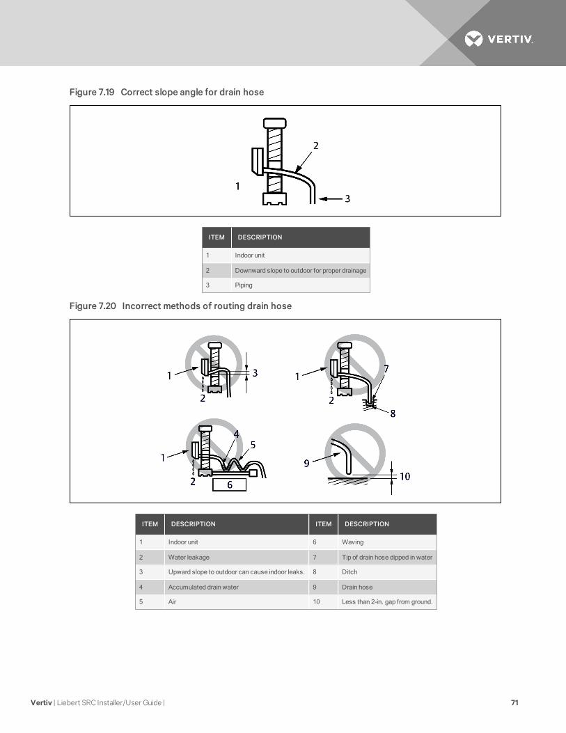
Figure 7.19 Correct slope angle for drain hose
ITEM DESCRIPTION
1 Indoor unit
2 Downward slope to outdoor for proper drainage
3 Piping
Figure 7.20 Incorrect methods of routing drain hose
ITEM DESCRIPTION ITEM DESCRIPTION
1 Indoor unit 6 Waving
2 Water leakage 7 Tip of drain hose dipped in water
3 Upward slope to outdoor can cause indoor leaks. 8 Ditch
4 Accumulated drain water 9 Drain hose
5 Air 10 Less than 2-in. gap from ground.
Vertiv | Liebert SRC Installer/User Guide | 71

7.4.4 Installing a Drain Hose on the Outdoor Unit
Depending on the installation site, it may be necessary to install a drain plug (factory-supplied).
1. Depending on your unit model, refer to Figure 7.21 below. or Figure 7.22 on the facing page.and to Table 7.12 below, for the drain-connection components.
2. Connect a field-suppled hose to the drain connections (A). If the hose is too long, position itcarefully to prevent kinks.
LABEL
QUANTITY, EACH
COMPONENT
SRC18 SRC24, SRC36
1 1 1 Drain connection
2 3 1 Drain cap
3 1 1 Drain washer
Table 7.12 Outdoor unit drain-connection components
NOTE: Do not use a drain hose with the outdoor unit in cold climates, otherwise the drain water mayfreeze and impair heating performance.
Figure 7.21 Outdoor unit drain-connection components for SRC18
Vertiv | Liebert SRC Installer/User Guide | 72

Figure 7.22 Outdoor unit drain-connection components for SRC24 and SRC36
7.4.5 Connecting Piping on the Outdoor Unit
1. Remove the tubing cover by loosening the fastening screws, Figure 7.23 below.
NOTE: When tightening the flare nut with a torque wrench, make sure the direction for tighteningfollows the arrow on the wrench.
Figure 7.23 Removing connection cover from outdoor unit
ITEM DESCRIPTION
1 Terminal block
2 Terminal-block cover
3 Tubing cover
Vertiv | Liebert SRC Installer/User Guide | 73

2. Align the center of the refrigerant pipe and corresponding connection as shown in Figure 7.24below.
Figure 7.24 Align center of piping connection
3. Refer to Figure 7.25 on the facing page, for correct liquid and gas pipe attachment to theoutdoor unit.
4. Place a couple of drops of refrigerant oil on the opening rim of the flare before assembling,making sure that you do not introduce any contaminants, and tighten the flare nut by hand.
5. Following the torque guidelines in Table 7.13 below, finish tightening the flare nut with atorque wrench until the wrench clicks referring to Figure 7.25 on the facing page, for correctconnection points.
NOTE: When tightening the flare nut with a torque wrench, make sure the direction for tighteningfollows the arrow on the wrench.
PIPE SIZE (IN. O.D.) TIGHTENING TORQUE (FT-LBS)
1/4 13.9 – 18
3/8 24.5 – 30.3
1/2 39.7 – 47.7
5/8 45.5 – 59.2
3/4 71.6 – 87.5
Table 7.13 Tightening torque for flare nuts
Vertiv | Liebert SRC Installer/User Guide | 74

Figure 7.25 Correct piping attachment for outdoor unit
ITEM DESCRIPTION ITEM DESCRIPTION
1 Outdoor unit 3 Liquid side piping (smaller diameter)
2 Gas side piping (larger diameter) 4 Torque wrench
7.4.6 Connecting Piping on the Indoor Unit
While following this procedure, refer to Pipe Bundling on page 68 for specific bundling instructions, and toRouting the Drain Hose for Indoor Unit on page 70 for proper drainage slope during piping.
1. Pull the screw cap at the bottom of the indoor unit.
2. Unscrew the 3 screws at the bottom of the chassis cover, Figure 7.26 on the next page, andremove the chassis cover, taking care not to scratch the main horizontal vane.
Vertiv | Liebert SRC Installer/User Guide | 75

Figure 7.26 Removing the chassis cover from indoor unit
ITEM DESCRIPTION
1 Chassis cover
3. From the rear of the indoor unit, pull the tubing holder away from the unit as shown in Figure7.27 below.
4. Remove the pipe port cover.
5. Position the tubing by unfolding the tubing and bending the tubing slowly downward first, asshown in Figure 7.27 below.
NOTE: Bending the tubing directly left or right, without bending downward first, may cause damage.
Figure 7.27 Bending drain tubing at rear of indoor unit
ITEM DESCRIPTION
1 Unfold slowly downward
2 Bend from downward position
Vertiv | Liebert SRC Installer/User Guide | 76

6. As shown in Figure 7.28 below, the fully encase the connection pipe and the indoor-unit pipein insulation material by binding them together using vinyl tape. Make sure there are not gapswhen binding.
Figure 7.28 Piping connection with insulation material
ITEM DESCRIPTION
1 Insulationmaterial
7. Make sure the tube cutting line is placed upward, Figure 7.29 below.
Figure 7.29 Correct cutting line placement
ITEM DESCRIPTION ITEM DESCRIPTION
1 Cutting line 4 Liquid pipe
2 Cutting line 5 Correct
3 Incorrect 6 Gas pipe
Vertiv | Liebert SRC Installer/User Guide | 77

8. Use narrow type vinyl tape, and make sure that the section placed in the rear pipe housing iswrapped sufficiently.
9. Continue to wrap the indoor-unit pipe connection to the outdoor-unit as shown in Figure 7.30below.
Figure 7.30 Wrapping connection pipe to indoor-unit pipe
ITEM DESCRIPTION ITEM DESCRIPTION
1 Connection pipe 5 Connection cable
2 Indoor-unit pipe 6 Pipe
3 Wrap with vinyl tape 7 Vinyl tape (narrow)
4 Vinyl tape (wide)
10. Using a wider vinyl tape, bundle the piping and the drain hose together, Figure 7.31 below.
• The tape should cover the piping and fit into the rear pipe housing on the back of theindoor unit as shown in Figure 7.32 on the facing page.
Figure 7.31 Bundling pipe and drain hose at rear of indoor unit
ITEM DESCRIPTION ITEM DESCRIPTION
1 Pipe 3 Vinyl tape (wide)
2 Wrap with vinyl tape. 4 Drain hose
Vertiv | Liebert SRC Installer/User Guide | 78

Figure 7.32 Piping bundle placement in housing at rear of indoor unit
ITEM DESCRIPTION ITEM DESCRIPTION
1 Drain hose 4 Drain hose
2 Tape 5 Connecting pipe
3 Connecting cable
7.5 Insulating Refrigeration Piping
To prevent heat loss/heat gain through the refrigerant piping, all refrigerant piping, including liquid linesand vapor lines, must be insulated separately. Insulation must be a minimum 1/2-in. thick, and thethickness may need to be increased based on ambient conditions and local codes. All refrigerant piping,including field-supplied isolation ball valves, service valves, and elbows must be completely insulatedusing closed-cell pipe insulation. All insulation joints must be glued with no air gaps. Insulation materialmust fit snugly against the refrigerations pipe with now space between it and the pipe. Insulation passingthrough pipe hangers, inside conduit, and/or sleeves must not be compressed. Protect insulation insidehangers and supports with a second layer. All pipe insulation exposed to direct sunlight anddeterioration-producing elements must be properly protected with a PVC-aluminum vapor-barrier jacket,or placed in a weather-resistant enclosure such as a pipe rack with a top cover. The design engineershould perform calculations to determine if the factory-supplied insulation jackets have sufficientthickness to meet local codes and to void sweating at job-site conditions. Maximum refrigerant-pipetemperature is 227°F. Minimum refrigerant-pipe temperature is –4°F. Add additional insulation ifnecessary.
NOTE: Do not insulate gas and liquid pipes together as this can result in pipe leakage and malfunctiondue to extreme temperature fluctuations. Be sure to fully insulate the piping connections.
Vertiv | Liebert SRC Installer/User Guide | 79

Figure 7.33 Typical pipe-insulation, power wire, and communications-cable arrangement
ITEM DESCRIPTION ITEM DESCRIPTION
1 Liquid pipe 4 Insulation
2 Gas pipe 5 Communication cable
3 Power wiring
Figure 7.34 Typical butt-joint insulation at indoor unit
ITEM DESCRIPTION
1 Surface of indoor-unit casing
2 Field-supplied pipe insulation
Vertiv | Liebert SRC Installer/User Guide | 80

Figure 7.35 Typical refrigerant flare-fitting insulation
ITEM DESCRIPTION
1 Field-supplied insulation
7.5.1 Minimum Requirements for Wall Thickness of Ethylene Propylene Diene Methylene (EPDM) Pipe Insulation
NOTE: Follow local codes when selecting EPDM insulation wall thickness.
CLASSIFICATION
AIR-CONDITIONED LOCATION NON-AIR-CONDITIONED LOCATION
1. TYPICAL LOCATION 2. SPECIAL LOCATION 3. TYPICAL LOCATION 4. SPECIAL LOCATION
Liquid pipe
1/4 in.1/2 in. 1/2 in. 1/2 in. 1/2 in.
3/8 in.
>1/2 in. 1/2 in. 1/2 in. 1/2 in. 1/2 in.
Vapor
3/8 in.
1/2 in.3/4 in. 3/4 in.
1 in.
1/2 in.
5/8 in.
3/4 in.
7/8 in.
1 in.
1-1/8 in.
3/4 in.
1-1/4
1 in. 1 in.1-3/8 in.
1-1/2 in.
1-3/4 in.
Table 7.14 Insulation guidelines for typical and special circumstances
Vertiv | Liebert SRC Installer/User Guide | 81

The classification descriptions are:
1. Typical location (air-conditioned): When the piping passes through and indoor area where theindoor unit operates.
• Apartment, classroom, office, mall, hospital, etc.
2. Special location (air-conditioned):
a. When the location is air-conditioned, but there is severe temperature/humidity differencedue to high ceilings.
Church, auditorium, theater, lobby, etc.
b. When the location is air-conditioned, but internal temperature/humidity are high.
Bathroom, swimming pool, locker room, etc.
3. Typical location (non air-conditioned): When the piping passes through an indoor area wherethe indoor unit does not operate.
• Hallway, dormitory, school, etc.
4. Special location (non air-conditioned): If the following conditions are present:
a. When the piping passes through an indoor area where the indoor unit does not operate.
b. When the humidity is high and there is no air flow in the location where the piping isinstalled.
The thickness of the above insulation material is based on heat conductivity of 0.61Btu/in/h/ft2/°F.
7.6 Air Purging
Air purging is performed after all piping is connected between the indoor and the outdoor unit. This stepis necessary to be sure that air refrigerant can flow through the system without the danger of leakage orpressure issues. Air and moisture that is left in the ping can lead to undesirable results and can causedamage to the working unit. it is important to go through a complete air-purging cycle to be sure that thelines are cleared out. Note that you may have to repeat this process if any air or moisture is found toremain in the piping. After air purging and evacuating the lines, be sure do a leak test for all piping andtubing.
Insufficient or incorrectly-performed air purging may lead to the following:
• Pressure in the system can rise.
• Operating current can rise.
• Cooling or heating efficiency falls.
• Moisture in the refrigerant circuit may freeze and block capillary tubing.
• Water can lead to corrosion of parts in the system.
To purge the air from the system:
1. Verify that each set of pipes (liquid and gas) are properly connected between the indoor andoutdoor unit.
2. Verify that all wiring for a test run is complete.
3. Remove the service-valve caps from the gas and liquid valves at the outdoor unit, Figure 7.36on the facing page.
• Keep both liquid and gas service valves closed at this step.
Vertiv | Liebert SRC Installer/User Guide | 82

Figure 7.36 Removing service-valve caps from outdoor unit for purging
ITEM DESCRIPTION ITEM DESCRIPTION
1 Outdoor unit 4 Valve caps
2 Gas side 5 3-way valve (close)
3 Liquid side 6 2-way valve (close)
Vertiv | Liebert SRC Installer/User Guide | 83

4. Set-up the purging-hose connections, Figure 7.37 below.
Figure 7.37 Evacuation set up
ITEM DESCRIPTION ITEM DESCRIPTION
1 Indoor unit 6 Lo = open
2 Piping bundle 7 Hi = close
3 Outdoor unit 8 Charge hose
4 Manifold valve 9 Vacuum pump
5 Pressure gauge
5. Do a leak test per Piping Leak Test below.
• A successful leak test must be completed before beginning evacuation.
6. Refer to Evacuation on page 86 to complete the purge process.
7.6.1 Piping Leak Test
Perform the leak test by pressurizing nitrogen gas to 550 psi on both the liquid and gas pipes. Test withthe piping service valves closed. if the pressure does not drop for 24 hours, the system passes the test. Itthe pressure drops, there is a nitrogen leak in the system. Find the leak, repair it, and test again.
WARNING! Risk of using combustible gases. Can cause explosion and fire resulting in buildingand equipment damage, serious injury or death. Do not use combustible gases, includingoxygen for leak detection. Use only inert gas (nitrogen) when checking plumbing leaks,cleaning or repairing pipes, etc.
Vertiv | Liebert SRC Installer/User Guide | 84
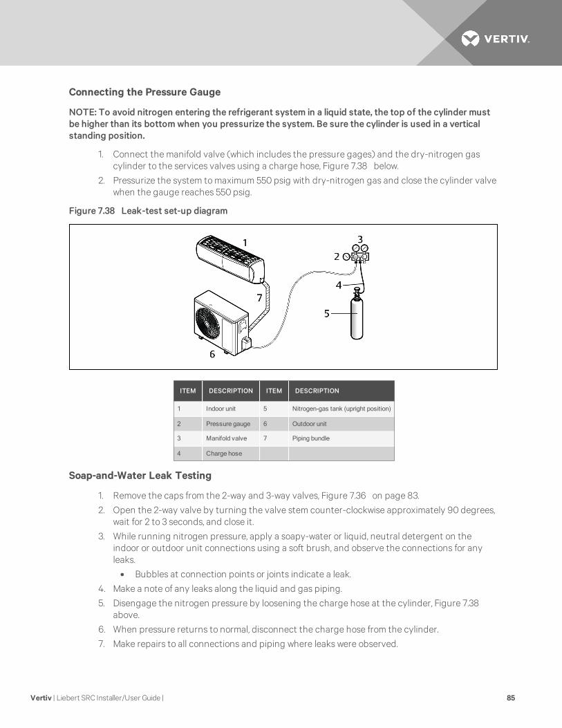
Connecting the Pressure Gauge
NOTE: To avoid nitrogen entering the refrigerant system in a liquid state, the top of the cylinder mustbe higher than its bottom when you pressurize the system. Be sure the cylinder is used in a verticalstanding position.
1. Connect the manifold valve (which includes the pressure gages) and the dry-nitrogen gascylinder to the services valves using a charge hose, Figure 7.38 below.
2. Pressurize the system to maximum 550 psig with dry-nitrogen gas and close the cylinder valvewhen the gauge reaches 550 psig.
Figure 7.38 Leak-test set-up diagram
ITEM DESCRIPTION ITEM DESCRIPTION
1 Indoor unit 5 Nitrogen-gas tank (upright position)
2 Pressure gauge 6 Outdoor unit
3 Manifold valve 7 Piping bundle
4 Charge hose
Soap-and-Water Leak Testing
1. Remove the caps from the 2-way and 3-way valves, Figure 7.36 on page 83.
2. Open the 2-way valve by turning the valve stem counter-clockwise approximately 90 degrees,wait for 2 to 3 seconds, and close it.
3. While running nitrogen pressure, apply a soapy-water or liquid, neutral detergent on theindoor or outdoor unit connections using a soft brush, and observe the connections for anyleaks.
• Bubbles at connection points or joints indicate a leak.
4. Make a note of any leaks along the liquid and gas piping.
5. Disengage the nitrogen pressure by loosening the charge hose at the cylinder, Figure 7.38above.
6. When pressure returns to normal, disconnect the charge hose from the cylinder.
7. Make repairs to all connections and piping where leaks were observed.
Vertiv | Liebert SRC Installer/User Guide | 85

8. When repairs are complete, repeat the leak test using nitrogen pressure and check for furtherleaks.
9. Once the piping system is leak-free, proceed to Evacuation below.
Ambient Temperature for the Leak Test
If the ambient temperature changed between the time when the pressure was applied and when thepressure-drop was checked, adjust the results by factoring-in approximately 1.45 psi for each 2°F oftemperature difference.
Correction formula = (Ambient temperature when pressure was applied – Ambient temperature whenpressure drop was checked) x 0.01.
For example:
When pressure (550 psig) was applied, the ambient temperature was 80.6°F. When the pressure drop waschecked 24 hours later (540 psi), the ambient temperature was 68°F.
Therefore, 80.6 – 68 x 0.01 = 0.126. In this case, the pressure drop of 0.126 was due to temperaturedifference, and there is no leak in the refrigerant-piping system.
7.6.2 Evacuation
After successfully completing leak testing, use the same hook-up described in Evacuation set up onpage 84, to perform the evacuation procedure.
NOTE: Be sure to use a manifold valve for air purging. If it is not available, use a stop valve. Be sure thatthe knob of the 3-way valve is always kept closed.
To evacuate the system:
1. Confirm that the “Lo” knob of the manifold valve is open, see Figure 7.37 on page 84.
2. Confirm that the “Hi” know of the manifold valve is closed.
3. Run the vacuum pump until the system is evacuated down to 300 microns, and continue torun the pump an additional 15 minutes.
NOTE: The duration of running the vacuum pump will vary according to pipe length and pump capacity.Refer to Table 7.15 below for accurate time duration.
TUBING LESS THAN 33 FT. TUBING MORE THAN 33 FT.
10minutes or more 15minutes or more
* Required time for evacuation when 30-gal/h vacuum pump is used.
Table 7.15 Evacuation timing*
4. When appropriate time has elapsed, turn-off the pump and leave the connections secured onthe service valves for 5 minutes.
5. If the system fails to hold 500 microns or less, check all connections for a tight fit and repeatthe evacuation steps.
6. When the correct vacuum is reached, close the “Lo” know of the manifold valve and stop thevacuum pump.
Vertiv | Liebert SRC Installer/User Guide | 86

7.6.3 Removing Purge and Test Equipment
When evacuation is completed, turn-off all valves a t the outdoor unit and safely disengage the manifoldvalve and vacuum pump using the following steps.
1. Using a wrench, turn the valve of the liquid stem counter-clockwise to fully open the valve, seeEvacuation set up on page 84.
2. Turn the valve of the gas temp counter-clockwise to fully open the valve.
3. Loosen the charge hose connected to the gas-side service port slightly to release the pressure,and remove the hose.
4. Replace the flare nut and its cap on the gas service port, and fasten the flare nut securelyusing an adjustable wrench.
• This step is very important to prevent leakage from the system.
5. Replace the valve caps at both gas- and liquid-side service valves and fasten them tightly.
Vertiv | Liebert SRC Installer/User Guide | 87

Vertiv | Liebert SRC Installer/User Guide | 88
This page intentionally left blank.

8 ELECTRICAL CONNECTIONS
WARNING! Arc flash and electric shock hazard. Open all local and remote electric power-supplydisconnect switches, verify with a voltmeter that power is Off and wear personal protectiveequipment (PPE) per NFPA 70E before working within the electric control enclosure. Failure tocomply can cause serious injury or death. Customer must provide earth ground to unit, perNEC, CEC and local codes, as applicable. Before proceeding with installation, read allinstructions, verify that all the parts are included and check the nameplate to be sure thevoltage matches available utility power. The Liebert controller does not isolate power from theunit, even in the “Unit Off” mode. Some internal components require and receive power evenduring the “Unit Off” mode of the controller. The only way to ensure that there is NO voltageinside the unit is to install and open a remote disconnect switch. Refer to unit electricalschematic. Follow all local codes.
Do not connect ground wire to refrigerant, gas or water piping, to lightning rods, to telephone groundwiring, or to the building plumbing system.
Replace and securely fasten all control box and panel covers immediately after working on the unit toprotect the operator from the hazards noted.
NOTICE
Risk of electrical phase reversal. Can cause equipment damage, unit malfunction and loss ofcooling operation.
If there is a possibility of reversed phase, phase loss, momentary blackout, or the power goes onand off while the system is operating, install a field-supplied phase-loss protection circuit.
NOTE: Consider ambient conditions (temperature, direct sunlight, inclement weather, etc.) whenselecting, installing, and connecting the power wiring.
8.1 Power-supply and Power-wiring Specifications
• Liebert SRC systems operate at 1Ø, 208 – 230 V, 60 Hz.
• Power-supply wire type and size should be selected based on National Electrical Code andlocal codes. Maximum allowable voltage fluctuation ±10% or nameplate rated value. Refer toFigure 8.1 on the next page for wiring guidelines.
• Properly ground the indoor and outdoor unit per National Electrical Code and local codes.
• Use only copper wiring that is stranded and shielded with the wires separately insulated.
• Ground wire should be longer than the common power/communication wires.
• Refer to the appropriate circuit and terminal-block diagrams for your model unit.
• Always match color codes of each wire and follow wiring diagram.
Vertiv | Liebert SRC Installer/User Guide | 89

Figure 8.1 Indoor and Outdoor wiring and communications cable diagram
ITEM DESCRIPTION ITEM DESCRIPTION
1 Power wiring, ground to outdoor unit 4 For 9/12/18K indoor units: AWG 18
2Power wiring, ground, communication cablefrom outdoor unit to indoor unit
5 GN/YL =Ground, Yellow
3For 9/12K indoor units: AWG 14For 18K indoor units: AWG 12
Best practice dictates using ring or spade terminals to terminate power wiring at the power terminal block,Figure 8.2 below.
Figure 8.2 Typical ring terminal
ITEM DESCRIPTION
1 More than 5 mm
2 Ring terminal
3 Power wiring
Vertiv | Liebert SRC Installer/User Guide | 90

WARNING! Risk of improper electrical connection termination. Can cause building andequipment damage, excessive heat at the terminations, smoke, fire, electric shock, seriousinjury and death. Do not terminate different gauge wires to the power terminal block. Slack inthe wiring may generate heat and fire.Do not ground the shield of the communications cable tothe indoor unit frame or other grounded entities of the building.
If ring terminals or space clips are not available then:
• When terminating wires of the same thickness, follow the instructions in Figure 8.3 below.
• Attach the wire securely without placing external force on the terminal block.
• Use an appropriately-sized screwdriver to tighten the terminals.
• Do not over-tighten the connections. Over-tightening may damage the terminals.
• Never apply line-voltage power to the communications-cable terminal block. If contact is made,the PCBs may be damaged.
• Always include some allowance in the wiring length when terminating. Provide some slack tofacilitate removal of electrical panels when servicing.
Figure 8.3 Proper and Improper power-wiring connections
ITEM DESCRIPTION
1 Copper wire.
2 Terminatemultiple power wires of the same gauge to both sides.
3 Do not terminate two wires on one side.
4 Do not terminate different gauge wires to a terminal block.
Vertiv | Liebert SRC Installer/User Guide | 91

8.2 Communication-cable Specifications
• Use a 4 conductor, shielded, stranded cable between the outdoor unit and the indoor unit.
• Minimum 18-gauge shielded CVVS or CPEVS cable.
• Insulation materials as required by local code.
• Rated for continuous exposure of temperatures up to 140°F.
• Maximum allowable cable length: 984 ft.
• Firmly attach the cable. Provide slack but secure in a way to prevent external forces from beingimparted on the terminal block.
• Terminate the cable shield to a grounded surface at the outdoor unit only.
• Always verify that the communication cable is connected to a communications terminal on theunit. Never apply line-voltage power to the communication-cable connection. If contact ismade, PCBs may be damaged.
• The shield of the communication cable connecting the outdoor unit to the indoor unit shouldbe grounded only to the outdoor-unit frame.
• Tie the shield of each cable segment together using a wire nut at each indoor unit. Maintainpolarity through the communication network.
• Never use a common multiple-core communication cable. Each communications bus must beprovided a separate cable (that is, between the outdoor unit and indoor unit).
8.3 Communication Cables between the Unit and Controller
• Field-supplied, 18 gauge, stranded 4-conductor communication cable (shielded).
• All insulation material as recommended by local code.
• Starting at the outdoor unit, terminate the cable on terminals Internet A and Internet B. Routethe cable as needed between each device.
8.4 Connecting Outdoor Unit Electrical Wiring
WARNING! Arc flash and electric shock hazard. Open all local and remote electric power-supplydisconnect switches, verify with a voltmeter that power is Off and wear personal protectiveequipment (PPE) per NFPA 70E before working within the electric control enclosure. Failure tocomply can cause serious injury or death. Customer must provide earth ground to unit, perNEC, CEC and local codes, as applicable. Before proceeding with installation, read allinstructions, verify that all the parts are included and check the nameplate to be sure thevoltage matches available utility power. The Liebert controller does not isolate power from theunit, even in the “Unit Off” mode. Some internal components require and receive power evenduring the “Unit Off” mode of the controller. The only way to ensure that there is NO voltageinside the unit is to install and open a remote disconnect switch. Refer to unit electricalschematic. Follow all local codes.
The general guidelines for the electrical and communication cables to the outdoor unit are the same foreach system. However, the actual connections on the terminal block will differ. Refer to each figure for themodel you are installing for the correct wiring of each terminal block.
• Verify that a circuit breaker or some other emergency-power cutoff device is in place beforeany power wiring is done to the system.
• Never touch any power lines or live cables before power is cut-off to the system.
Vertiv | Liebert SRC Installer/User Guide | 92

• Familiarize yourself with the location of the circuit breaker.
To connecting the wiring:
1. Using a Phillips-head screwdriver, remove the conduit-panel cover from the outside of the unit.
2. Inspect all wiring inside the casing to make sure that they are secure and have not come looseduring transportation and installation.
• Loose wires can cause the wiring to burn-out quickly.
• Inspect wires for damage or cracks (manufacturing defects).
3. Confirm that the Electrical power-supply capacity is sufficient to run the unit. Refer to thespecifications in Electrical Data on page 21.
4. Confirm that you are using the correct wire gauge size to proceed.
5. Using a screwdriver, refer to Figure 8.4 below, and connect the wires as follows:
• Securely attach each wire to the terminal block.
• Bundle cabling using a cable restrainer.
• Pay attention to the location/connection of the green/yellow grounding cable. In somemodels, the connection is located on the side of the actual terminal block.
• Maintain a minimum of 0.2-in. of wire length from the terminal block to cable bundle.
Figure 8.4 Outdoor-unit terminal-block connections
ITEM DESCRIPTION ITEM DESCRIPTION
1 Terminal Block 5 Connection/Communication cable (leading to indoor unit)
2 Power 6 Conduit-panel cover
3 To indoor unit 7 Power cord
4 Conduit panel 8 More than 0.2 in.
Vertiv | Liebert SRC Installer/User Guide | 93

6. Use a recognized circuit breaker between the power source and the unit. A disconnectingdevice to adequately disconnect all supply lines must be fitted.
Figure 8.5 below shows an example of how a circuit breaker should be wired through the Liebert SRCsystem.
Figure 8.5 Circuit breaker wiring
ITEM DESCRIPTION
1 Main power source
2 Air conditioner
3Circuit breakerUse a circuit breaker or time-delay fuse.
8.5 Thermostat Installation and Wiring
NOTICE
Risk of improper thermostat installation. Can cause unit malfunction.
• Installation work must be performed in accordance with the national wiring standardsand local code by authorized personnel only.
• If local electric and building code requires plenum(CMP) cable, use an enclosed, non-combustible conduit (metal raceway) or FT-6 rated or above cable.
• When using back cable-entry, AWG#22, 3 core shielded wire is recommended.
• When using top or right-side cable entry, AWG#24, 3 core shielded wire is recommended.
• Do not bury the thermostat in the wall. This can damage the temperature sensor.
• Do not install a cable 164 ft (50 m) or longer. This can cause communication errors.
NOTE: If the distance between the thermostat and the indoor unit is longer than 32 ft (10 m), use anextension cable.
Vertiv | Liebert SRC Installer/User Guide | 94

Because the room-temperature sensor is in the thermostat, it should be installed in a place away fromdirect sunlight, high humidity, and direct supply of cold air to maintain proper temperature of the space.Install the thermostat about 5 ft. (1.5 m) above the floor in an area with good air circulation at an averagetemperature, Figure 8.6 below.
Do not install the thermostat where it can be affected by the following:
• Drafts or dead spots behind doors and in corners.
• Hot or cold air from ducts.
• Radiant heat from sun or appliances.
• Concealed pipes or chimneys.
• Uncontrolled areas such as on an outside wall.
The thermostat is equipped with an LCD display and should be installed at the recommended height forproper view of the display.
Figure 8.6 Proper and Improper thermostat locations
ITEM DESCRIPTION ITEM DESCRIPTION
1 Direct sun-ray contact area 3 Improper location
2 Proper location 4 5 ft (1.5 m) above floor
Vertiv | Liebert SRC Installer/User Guide | 95

To install the thermostat:
1. Once the proper location for the thermostat is determined, determine the cable-entry locationfrom one of three options:
• Back
• Top
• Right
2. If you use top or right-side entry, remove the cable-guide groove from the back plate with long-nose pliers, Figure 8.7 below.
Figure 8.7 Cable-entry hole/guide grooves
ITEM DESCRIPTION
1 Back entry (through wall)
2 Top entry
3 Right-side entry
3. Place the back plate in the installation location and secure it with screw, Figure 8.8 below.
• Do not bend the back plate when tightening screws.
• If there is an electric box, fit the back plate to the box when installing.
• Do not leave a gap between the wall and back plate or the thermostat could move orshake.
Figure 8.8 Thermostat back plate installation
Vertiv | Liebert SRC Installer/User Guide | 96

4. Making sure that the cable does not interfere, place the upper part of the thermostat on theback plate as shown in Figure 8.9 below, and press the lower part onto the back plate toconnect it.
• Leave no gaps between the thermostat and the back plate.
• To remove the thermostat from the back plate, insert a screwdriver into one of theseparating holes on the bottom of the thermostat and twist. Repeat in the second hole, torelease the thermostat from the back plate.
Figure 8.9 Mounting thermostat onto back plate
ITEM DESCRIPTION
1 Connecting order
2 Disconnecting order
3 Wall side
Vertiv | Liebert SRC Installer/User Guide | 97

5. Refer to Figure 8.10 below to connect the indoor unit to the thermostat using the extensioncable.
NOTICE
Risk of improper thermostat installation. Can cause unit malfunction.
If local electric and building code requires plenum(CMP) cable, use an enclosed, non-combustible conduit (metal raceway) or FT-6 rated or above cable.
Figure 8.10 Extension cable from indoor unit to thermostat
ITEM DESCRIPTION ITEM DESCRIPTION
1 AWG#24 5 Extension cable (housing type)
2 AWG#22 6 C/BOX cable (plug type)
3 AWG#22 7 Indoor-unit side
4 Make sure connectors are properly connected.
6. To connect the extension cable directly to the thermostat
• Loosen the screw holding the cable in the thermostat terminal block.
• Use a cutting nipper to remove the housing from the extension cable and peel it as shownin Figure 8.11 below.
Figure 8.11 Thermostat cable prep
Vertiv | Liebert SRC Installer/User Guide | 98

7. Connect the wires to the thermostat terminal block and the indoor-unit terminal block asshown in Figure 8.12 below.
• Tighten securely and make sure wires are not touching each other.
Figure 8.12 Thermostat and Indoor unit terminal-block connections
ITEM1
THERMOSTATPCB5
INDOOR-UNIT SIDEFUNCTION
2 YELLOW YL Signal
3 RED RD 12 V
4 BLACK BK GND
Vertiv | Liebert SRC Installer/User Guide | 99

Vertiv | Liebert SRC Installer/User Guide | 100
This page intentionally left blank.

9 INSTALLATION SET-UP AND SYSTEM START-UPNOTICE
Risk of improper thermostat installation. Can cause unit malfunction.
The Installer setting mode sets up the detailed function of the thermostat.
If the installation is not set correctly, it can cause problems for the product, user injury, orproperty damage. Installation set-up must be performed by a certified technician. Non-certified personnel attempting to install or make changes shall be responsible for any adverseeffects or operation.
9.1 Accessing Installer Set-up Mode
1. On the thermostat, press for at least 3 seconds.The function code displays.
NOTE: A press less than 3 seconds enters “user” settings mode.
2. Refer to the following procedures and Table 9.1 below to make the correct settings for yourinstallation.
NOTE: Some menu options and functions may not be displayed or the menu name may be differentdepending on your system and model.
FUNCTION CODE DESCRIPTION VALUE
01 Test Run 01 =Set
02 Address Setting 00 ~FF =Address
03E.S.P Value
Step:
01 =Very Low
02 =Low
03 =Med
04 =High
05 =Very High
Value:
0 ~ 255
04 Thermistor
01 =Remo
02 = Indoor
03 = 2TH
05 Ceiling Height
01 = Low
02 =Med
03 =High
04 =Very High
Table 9.1 General unit functions—Installer set-up codes
Vertiv | Liebert SRC Installer/User Guide | 101

FUNCTION CODE DESCRIPTION VALUE
06 Static Pressure
01 =V-H
02 =F-H
03 =V-L
04 =F-L
07 Master setting
00 =Slave
01 =Master
(only “Plus 1 series models)
00 =Group
01 =Single
08 Override setting00 =Slave
01 =Master
09 Dry contact00 =Auto-off
01 =Auto-on
12 Celsius/Fahrenheit00 =Celsius
01 =Fahrenheit
18 Emergency heater
Select mode:
00 = not used
01 =use
Low-ambient heating operation:
0 = not used
1 = compressor off 0°F (–18°C)/ on 5°F (–15°C)
2 = compressor off 5°F (–15°C)/ on 10°F (–12°C)
3 = compressor off 10°F (–12°C)/ on 15°F (–9°C)
Fan speed:
0 = fan off
1 = fan on
20 Plasma
00 =not installed
01 = installed
21 Electric heater
22 Humidifier
23 Elevation grill
24 Ventilation kit
25 Auxiliary heater
31 Settings temperature range00 =60~86°F / 16~30°C
01 =40~99°F / 4~37.5°C
Somemenu options and functions may not be displayed or themenu namemay be different depending on your system andmodel.
Table 9.1 General unit functions—Installer set-up codes (continued)
Vertiv | Liebert SRC Installer/User Guide | 102

9.2 Running Test Mode
Before running test mode, make sure of the following:
• Leak testing is complete and there are no leaks.
• Air purge/evacuation is complete and successful.
• All tubing, piping, and wiring are properly connected.
1. On the thermostat, press for at least 3 seconds.The function code blinks in the lower-middle of the display.
NOTE: A press less than 3 seconds enters “user” settings mode.
2. Press .The test run starts.
• During the test run, pressing any of the following buttons will exit the test: Oper Mode,Temp up/down, Fan Speed, Wind Direction, or Start/Stop.
9.3 Setting the Address of Central Control
Refer to 9.1 on page 101 for the specific function-setting values.
1. On the thermostat, press for at least 3 seconds.The function code blinks in the lower-middle of the display.
NOTE: A press less than 3 seconds enters “user” settings mode.
2. Press repeatedly to select the function code.
3. Press , to select the Group No., then use to select the setting.
4. Press , to select the Indoor No., then use to select the setting.
5. Press .The setting is saved.
6. Press to exit installer setting mode.
NOTE: If there is no button input for 25 seconds, set-up mode is automatically exited. If you exit
without pressing , your settings are not saved.
Vertiv | Liebert SRC Installer/User Guide | 103
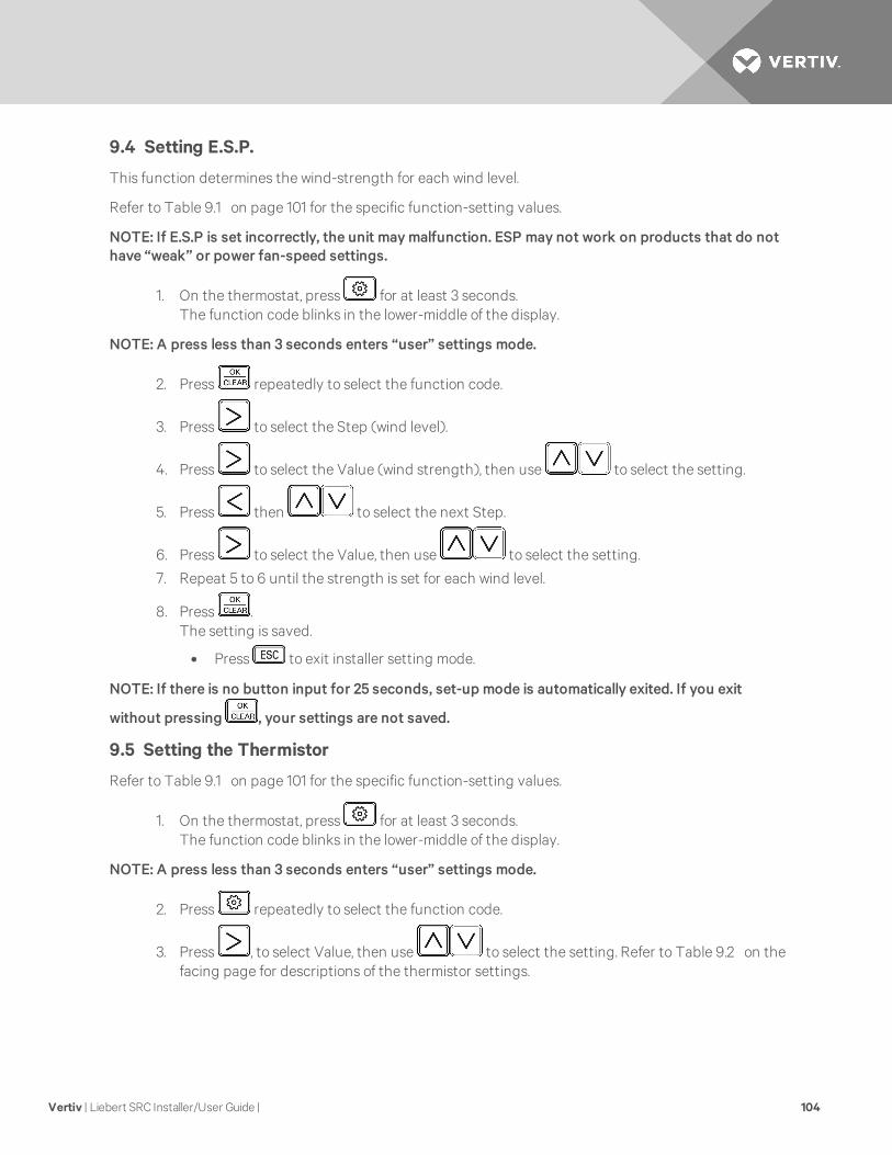
9.4 Setting E.S.P.
This function determines the wind-strength for each wind level.
Refer to Table 9.1 on page 101 for the specific function-setting values.
NOTE: If E.S.P is set incorrectly, the unit maymalfunction. ESP may not work on products that do nothave “weak” or power fan-speed settings.
1. On the thermostat, press for at least 3 seconds.The function code blinks in the lower-middle of the display.
NOTE: A press less than 3 seconds enters “user” settings mode.
2. Press repeatedly to select the function code.
3. Press to select the Step (wind level).
4. Press to select the Value (wind strength), then use to select the setting.
5. Press then to select the next Step.
6. Press to select the Value, then use to select the setting.
7. Repeat 5 to 6 until the strength is set for each wind level.
8. Press .The setting is saved.
• Press to exit installer setting mode.
NOTE: If there is no button input for 25 seconds, set-up mode is automatically exited. If you exit
without pressing , your settings are not saved.
9.5 Setting the Thermistor
Refer to Table 9.1 on page 101 for the specific function-setting values.
1. On the thermostat, press for at least 3 seconds.The function code blinks in the lower-middle of the display.
NOTE: A press less than 3 seconds enters “user” settings mode.
2. Press repeatedly to select the function code.
3. Press , to select Value, then use to select the setting. Refer to Table 9.2 on thefacing page for descriptions of the thermistor settings.
Vertiv | Liebert SRC Installer/User Guide | 104

4. Press .The setting is saved.
5. Press to exit installer setting mode.
NOTE: If there is no button input for 25 seconds, set-up mode is automatically exited. If you exit
without pressing , your settings are not saved.
VALUE FUNCTION
01 Thermostat Operates based on temperature sensor in thermostat.
02 Indoor Unit Operates based on temperature sensor in indoor unit.
03 2TH
CoolingOperates based on higher temperature comparing the reading from thermostattemp. sensor and indoor-unit temp sensor.
HeatingOperates based on lower temperature comparing the reading from thermostattemp. sensor and indoor-unit temp sensor.
The 2TH functions differently depending on product model.
If the indoor temperature is below 10°F, the value for the temperature sensor of the thermostat is displayed regardless of the thermistor setting.
Table 9.2 Thermistor setting options
9.6 Setting the Ceiling Height
Refer to Table 9.1 on page 101 for the specific function-setting values.
1. On the thermostat, press for at least 3 seconds.The function code blinks in the lower-middle of the display.
NOTE: A press less than 3 seconds enters “user” settings mode.
2. Press repeatedly to select the function code.
3. Press , to select the Value, then use to select the setting. Refer to Table 9.3below for descriptions of the ceiling-height settings.
VALUE FUNCTION
01 Low Decrease indoor air-flow rate 1 step from standard level.
02 Medium Set indoor air-flow rate as standard level.
03 High Increase indoor air-flow rate 1 step from standard level.
04 Very high Increase indoor air-flow rate 2 steps from standard level.
Table 9.3 Ceiling-height setting options
4. Press .The setting is saved.
5. Press to exit installer setting mode.
NOTE: If there is no button input for 25 seconds, set-up mode is automatically exited. If you exit
without pressing , your settings are not saved.
Vertiv | Liebert SRC Installer/User Guide | 105

9.7 Setting Fahrenheit/Celsius
Refer to Table 9.1 on page 101 for the specific function-setting values.
1. On the thermostat, press for at least 3 seconds.The function code blinks in the lower-middle of the display.
NOTE: A press less than 3 seconds enters “user” settings mode.
2. Press to select the function code.
3. Press , to select Value, then use to select the setting.
4. Press .The setting is saved.
5. Press to exit installer setting mode.
NOTE: If there is no button input for 25 seconds, set-up mode is automatically exited. If you exit
without pressing , your settings are not saved.
9.8 Setting Optional Functions
Used when options are added or removed.
Refer to Table 9.1 on page 101 for the specific function-setting values.
1. On the thermostat, press for at least 3 seconds.The function code blinks in the lower-middle of the display.
NOTE: A press less than 3 seconds enters “user” settings mode.
2. Press repeatedly to select the function code.
3. Press , to select the condition, then use to select the setting.
4. Press .The setting is saved.
5. Press to exit installer setting mode.
NOTE: A press less than 3 seconds enters “user” settings mode.
9.9 Setting Temperature Range
Refer to Table 9.1 on page 101 for the specific function-setting values.
1. On the thermostat, press for at least 3 seconds.The function code blinks in the lower-middle of the display.
NOTE: A press less than 3 seconds enters “user” settings mode.
2. Press repeatedly to select the function code.
Vertiv | Liebert SRC Installer/User Guide | 106

3. Press , to select the Value, then use to select the setting.
4. Press .The setting is saved.
NOTE: If there is no button input for 25 seconds, set-up mode is automatically exited. If you exit
without pressing , your settings are not saved.
Vertiv | Liebert SRC Installer/User Guide | 107

Vertiv | Liebert SRC Installer/User Guide | 108
This page intentionally left blank.

10 OPERATION10.1 Operating the Unit
Use the ON/OFF button on the indoor unit to operate the system.
1. Depending on the type of unit, Type 1 or Type 2, see Figure 10.1 below, open the front cover.
2. Press the ON/OFF button.
• If the horizontal vane opens rapidly, the stepping motor may be broken.
• The fan speed is set too high. Depending on the model, fan speed may be changed.
• You cannot change temperature using this ON/OFF button.
• For cooling-only models, the temperature is set to 71.6°F (22°C).
• For cooling-and-heating models, the temperature is set from 71.6°F (22°C) to 75.2°F(24°C).
Figure 10.1 On/Off button location
ITEM DESCRIPTION
1 Type 1
2 Type 2
3 On/Off
10.2 Automatic Unit Restart
When the unit is turned-on after a power failure, this function restores the previous settings.
NOTE: Auto-restart may be changed depending on the type of model.
To disable automatic restart:
1. Open the front cover of the indoor unit.
2. Press and hold the ON/OFF button for 6 seconds.The unit beeps twice and the lamp blinks 4 times.
• To re-enable Auto Restart, press and hold the ON/OFF button for 6 seconds.The unit beeps twice and the lamp blinks 4 times.
NOTE: Pressing and holding the ON/OFF button 3 to 5 seconds, instead of 6 seconds, initiates testoperation. In test operation, the unit blows strong, cool air fro 18 minutes then returns to factory-default settings.
Vertiv | Liebert SRC Installer/User Guide | 109

10.3 Enabling Cooling-only Mode
Cooling-only mode is used when performing the Pump Down procedure. Cooling-only mode is set in“Installer” mode.
• Automatic operation is suspended when cooling-only mode is initiated in Installer mode.
• When cooling-only mode is disabled, the unit returns to normal operation.
• Installer mode cannot be initiated if the unit is running. The system must be powered-offcompletely.
• All Installer-mode function codes must be entered while the system is powered-off (completesystem shutdown).
• WLAN module’s communication time will lag by about 1 minute after the unit is powered backon and normal operation resumes.
• Entire lock or Mode lock cannot be set if you set heating or automatic operation through thecentral controller.
To enable cooling-only mode:
1. Completely shut-down system power.
2. At the thermostat, access Installer mode by pressing for at least 3 seconds.The function code displays.
NOTE: A press less than 3 seconds enters “user” settings mode.
3. Press repeatedly to select the function code 4 5 , then power-on the unit.The unit beeps to acknowledge that the code is received.
4. Turn-off power for at least 30 seconds.
5. Turn-on power to the system.Cooling-only mode is enabled.
10.4 Disabling Cooling-only Mode
Cooling-only mode is used when performing the Pump Down procedure. Once pump-down is complete,disable cooling-only and return to normal operation using the following procedure.
1. Completely shut-down system power.
2. At the thermostat, access Installer mode by pressing for at least 3 seconds.The function code displays.
NOTE: A press less than 3 seconds enters “user” settings mode.
3. Press repeatedly to select the function code 4 6 , then power-on the unit.The unit beeps to acknowledge that the code is received.
4. Turn-off power for at least 30 seconds.
5. Turn-on power to the system.Cooling-only mode is disabled.
Vertiv | Liebert SRC Installer/User Guide | 110

10.5 Standard Operation
10.5.1 Selecting Cooling Mode
1. On the thermostat, press to power-on the indoor unit.
2. Press until displays in the operation-mode section.
3. Adjust the temperature setting by pressing .
NOTE: The temperature range varies depending on Installer set-up. Factory default is 64~86°F(18~30°C).
10.5.2 Selecting Power Cooling
Power cooling lets you cool or warm the indoor air quickly and is available with cooling, heating, anddehumidification modes.
1. On the thermostat, press to power-on the indoor unit.
2. Press until displays in the operation-mode section.
3. Press until Po displays under the Cooling-temperature setpoint in the temperaturesection.
10.5.3 Selecting Heating Mode
1. On the thermostat, press to power-on the indoor unit.
2. Press until displays in the operation-mode section.
3. Adjust the temperature setting by pressing .
NOTE: The temperature range varies depending on Installer set-up. Factory default is 64~86°F(18~30°C).
Vertiv | Liebert SRC Installer/User Guide | 111

10.5.4 Selecting Dehumidification Mode
Dehumidification removes moisture from a highly-humid environment, especially during the rainy season,to prevent mold from setting-in. Dehumidification mode adjusts room temperature and fan speedautomatically to maintain the optimal humidity level.
1. On the thermostat, press to power-on the indoor unit.
2. Press until displays in the operation-mode section.
10.5.5 Selecting Fan Mode
Fan mode circulates indoor air without changing the room temperature.
1. On the thermostat, press to power-on the indoor unit.
2. Press until displays in the operation-mode section.
10.5.6 Selecting Auto Mode
Auto mode changes modes automatically to maintain the temperature setpoint within ±3.6°F (±2°C).
When operating in auto mode, the Auto icon and cool, heat, etc. icon display simultaneously in theOperating Mode section to indicate the current mode.
1. On the thermostat, press to power-on the indoor unit.
2. Press until displays in the operation-mode section.
3. Set the cooling setpoint by pressing ,then adjust the temperature displayed
under Cool-temperature setpoint in the Temperature section of the display by pressing .
4. Set the heating setpoint by pressing ,then adjust the temperature displayed
under Heat-temperature setpoint in the Temperature section of the display by pressing .
Vertiv | Liebert SRC Installer/User Guide | 112

10.5.7 Selecting Timed Override
Timed override temporarily overrides the current schedule (occupied/unoccupied).
• Reverts to last occupied schedule in unoccupied override.
• Reverts to last unoccupied schedule in occupied override.
See Setting Override Time on page 115, to set the duration of the override.
Press for 3 seconds.Timed override is enabled.
• To cancel timed override, press for 3 seconds.Operation reverts to last weekly schedule.
10.5.8 Selecting Set Back
Set Back reverts to the last unoccupied schedule until set-back operation is canceled. If there is nounoccupied schedule, it returns to the default set-back setting. See Setting Set-back Temperature onpage 116, to set the set-back setting.
Press .Set back is enabled.
• To cancel set back, press .
NOTE: You cannot change settings in set-back mode. HL and the lock is displayed. Set back iscanceled if a command from another controller is received.
10.5.9 Setting the Temperature
You can adjust the temperature simply by pressing .
NOTE: In Auto mode, both setpoints adjust automatically when you set the temperature in this way. Toadjust the cooling or heating setpoint individually, press the appropriate button before adjusting thetemperature.
10.5.10 Adjusting Air Flow
1. Press to cycle through the fan-speed options (displayed in Fan Speed section).
2. Press to cycle through the wind-direction options (displayed in Air-flow/Louvers section).
Vertiv | Liebert SRC Installer/User Guide | 113

10.5.11 Selecting Energy-saving Cooling
Energy-saving cooling operation improves comfort and power-saving capacity by automatically adjustingtemperature during cooling mode.
NOTE: Energy-save mode can only be set up in Cooling mode and does not operate with Auto Mode.
1. Press until is displayed in the sub-function section of the display.
2. Press .The setting is saved.
3. Press to exit the sub-function set-up.
10.5.12 Selecting Automatic Drying
Automatic drying dries the inside of the indoor unit when it is turned-off by operating the fan to removemoisture and prevent mold.
1. Press until is displayed in the sub-function section of the display.
2. Press .The setting is saved.
3. Press to exit the sub-function set-up.
10.5.13 Selecting Fan Auto
Operates the fan when the outdoor unit is running.
1. Press until is displayed in the sub-function section of the display.
2. Press .The setting is saved.
3. Press to exit the sub-function set-up.
10.6 Function Settings
10.6.1 Setting Louver Angle Control
Adjusts the angle of airflow.
NOTE: While louver/vane angle is adjusted, commands from the central controller are delayed for 1minute
1. Press repeatedly until flashes in the Function Settings section of the display.
2. Press to select the vane number, or All to set all vanes at once (STD sets alllouvers to factory-default).
3. Press to select the angle, then press .
Vertiv | Liebert SRC Installer/User Guide | 114

4. Repeat 2 and 3 for each louver if needed.
5. When done, Press .The settings are saved.
6. Press to exit the function set-up.
10.6.2 Locking the Display
Locks the display to prevent un-authorized use.
1. Press repeatedly until flashes in the Function Settings section of the display.
2. Press to select , then press .The display is locked.
3. Press to exit the function set-up.
10.6.3 Setting the Minimum Difference between the Cooling and Heating Setpoints
1. Press repeatedly until flashes in the Function Settings section of the display.
2. Press to select the temperature, then press .The minimum difference is set.
3. Press to exit the function set-up.
10.6.4 Setting Current Time
1. Press repeatedly until flashes in the Function Settings section of the display.
2. Press to select the current day, then press to move to AM/PM setting.
3. Press to select AM/PM, then press to move to hour setting.
4. Press to select the hour, then press to move to minute setting.
5. Press to select minute, then press .Current time is set.
6. Press to exit the function set-up.
10.6.5 Setting Override Time
1. Press repeatedly until flashes in the Function Settings section of the display.
2. Press to select the duration of the override interval from 30 to 240 minutes.
3. Press .Override interval is set.
4. Press to exit the function set-up.
Vertiv | Liebert SRC Installer/User Guide | 115

10.6.6 Setting Set-back Temperature
1. Press repeatedly until flashes in the Function Settings section of the display, andthe Cool setpoint temperature flashes in the Temperature section.
2. Press to select the set-back cooling setpoint, then press , to move to the Heatsetpoint temperature.
3. Press to select the set-back heating setpoint, then press .The set-back setpoint temperatures are set.
4. Press to exit the function set-up.
10.6.7 Clearing the “Clean Filter” Alarm
1. Press repeatedly until flashes in the Function Settings section of the display.
2. Press .The display is cleared.
3. Press to exit the function set-up.
10.7 Schedule Set-up
10.7.1 Simple Schedule
A simple schedule automatically runs for a specified time then stops.
1. On the thermostat, press until displays in the Schedule section.
2. Press to select the sleep time from 1 to 3 hours.
3. Press .The schedule is set.
4. Press to exit the function set-up.
10.7.2 Setting a Sleep Schedule
A sleep schedule shuts-off the unit for a specified time.
1. On the thermostat, press until displays in the Schedule section.
2. Press to select the duration of the schedule from 1 to 7 hours.
3. Press .The schedule is set.
Vertiv | Liebert SRC Installer/User Guide | 116
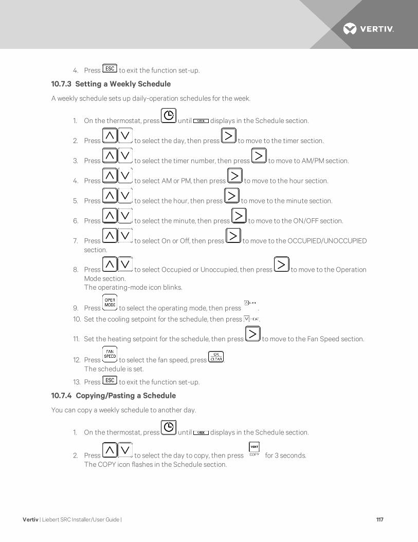
4. Press to exit the function set-up.
10.7.3 Setting a Weekly Schedule
A weekly schedule sets up daily-operation schedules for the week.
1. On the thermostat, press until displays in the Schedule section.
2. Press to select the day, then press to move to the timer section.
3. Press to select the timer number, then press to move to AM/PM section.
4. Press to select AM or PM, then press to move to the hour section.
5. Press to select the hour, then press to move to the minute section.
6. Press to select the minute, then press to move to the ON/OFF section.
7. Press to select On or Off, then press to move to the OCCUPIED/UNOCCUPIEDsection.
8. Press to select Occupied or Unoccupied, then press to move to the OperationMode section.The operating-mode icon blinks.
9. Press to select the operating mode, then press .
10. Set the cooling setpoint for the schedule, then press .
11. Set the heating setpoint for the schedule, then press to move to the Fan Speed section.
12. Press to select the fan speed, press .The schedule is set.
13. Press to exit the function set-up.
10.7.4 Copying/Pasting a Schedule
You can copy a weekly schedule to another day.
1. On the thermostat, press until displays in the Schedule section.
2. Press to select the day to copy, then press for 3 seconds.The COPY icon flashes in the Schedule section.
Vertiv | Liebert SRC Installer/User Guide | 117

3. Press to select day to which you want to paste the schedule, then press for 3seconds.
The icon flashes in the Schedule section, and the schedule is pasted.
4. Press to exit the function set-up.
10.7.5 Scheduling a Holiday
Schedules stop on the day reserved.
1. On the thermostat, press until displays in the Schedule section.
2. Press to select the day, then press .The holiday is set.
3. Press to exit the function set-up.
10.7.6 Delete all Schedules
On the thermostat, press and hold and simultaneously for 3 seconds.
Vertiv | Liebert SRC Installer/User Guide | 118

11 MAINTENANCE
WARNING! Arc flash and electric shock hazard. Open all local and remote electric powerdisconnect switches, verify with a voltmeter that power is Off and wear personal protectiveequipment (PPE) per NFPA 70E before working within the electric control enclosure. Failure tocomply can cause serious injury or death. The Liebert controller does not isolate power fromthe unit, even in the “Unit Off” mode. Some internal components require and receive powereven during the “Unit Off” mode of the controller. The only way to ensure that there is NOvoltage inside the unit is to install and open a remote disconnect switch. Refer to unit electricalschematic. Follow all local codes.
NOTICE
Risk of improper cleaning. Can cause cabinet finish damage.
• Never use water that is higher than 104° (40°C) when you clean the filters. It may causedeformation or discoloration.
• Never use volatile substances when you clean the filters. These may damage the surfaceof the unit.
• Do not wash the 3M filter (optional) with water because it can be damaged by water.
• Do not wash the Triple filter (optional) with water because it can be damaged by water.
If the unit will not be used for an extended period of time, dry the unit to maintain it in the best condition.Clean the unit regularly to maintain optimal performance and to prevent possible breakdown. For thecleaning schedule, see Cleaning Schedule on the next page.
• Dry the unit in Fan mode for 3 to 4 hours and disconnect the power. There may be internaldamage if moisture is left in unit’s components.
• Before using the unit again, dry the unit in Fan mode for 3 to 4 hours to remove odor generatedby moisture.
Figure 11.1 Cleaning the outside of the indoor unit
ITEM DESCRIPTION
1 Air filter
Vertiv | Liebert SRC Installer/User Guide | 119

COMPONENT DESCRIPTION INTERVAL
Air filter Clean with a vacuum or hand wash. 2 weeks
Triple filter Clean with a vacuum or brush. Every 3months
3M filter Clean with a vacuum or brush. Every 6months
Ionizer (optional) Use a dry cotton bud to remove any dust. Every 6months
Indoor unit
Clean the surface using a soft, dry cloth. Regularly
Have a professional clean the condensate drain pan. Once a year
Have a professional clean the condensate drain pipe. Every 4months
Outdoor unit
Have a professional clean the heat-exchanger coils and the panel vents. (Consult a technician.) Once a year
Have a professional clean the fan. Once a year
Have a professional clean the condensate drain pan Once a year
Have a professional verify that the fan assembly is firmly tightened. Once a year
Clean the electric components with air. Once a year
Table 11.1 Cleaning Schedule
11.1 Cleaning the Air Filter
Clean the air filter once every 2 weeks or more if necessary.
Note the following guidelines:
• Bending the air filter can break it.
• If the air filter is not assembled correctly, dust and other substances can enter the indoor unit.
11.1.1 Cleaning the Air Filter on Type 1 Units
1. Turn-off power and unplug the power cord.
2. Open the front cover by lifting both sides of the cover slightly.
3. Hold the knobs on the air filters, pull them down slightly and remove them from the unit, Figure11.2 below.
Figure 11.2 Removing the air filter from Type 1 unit
Vertiv | Liebert SRC Installer/User Guide | 120

4. Clean the filters with a vacuum cleaner or lukewarm water with a neutral detergent.
5. Dry the filters in the shade.
6. Insert the hooks of the air filters into the front cover, Figure 11.3 below, and make sure thefilters are inside the cover for correct assembly.
Figure 11.3 Inserting cleaned air filter in Type 1 unit
11.1.2 Cleaning the Air Filter on Type 2 Units
1. Turn-off power and unplug the power cord.
2. Hold the knobs on the air filters, lift up slightly, Figure 11.4 below.
Figure 11.4 Knobs on air filter of Type 2 unit
3. Remove them from the unit, Figure 11.5 below.
Figure 11.5 Removing the air filter from Type 2 unit
4. Clean the filters with a vacuum cleaner or lukewarm water with a neutral detergent.
5. Dry the filters in the shade.
6. Insert the hooks of the air filters into the front cover, Figure 11.6 below.
Figure 11.6 Inserting cleaned air filter on the hooks of the Type 2 unit
Vertiv | Liebert SRC Installer/User Guide | 121

7. Press down onto hooks, Figure 11.7 below, and make sure the filters are installed correctly.
Figure 11.7 Push down on the hooks of the Type 2 unit
11.2 Cleaning the Optional 3M or Triple Filter
1. Turn off power and unplug the power cord.
2. Remove the air filters from the unit.
3. Remove the 3M and/or Triple filters from the unit, Figure 11.8 below.
Figure 11.8 Removing 3M/Triple filters from indoor unit
ITEM DESCRIPTION
1 Type 1
2 Type 2
Vertiv | Liebert SRC Installer/User Guide | 122
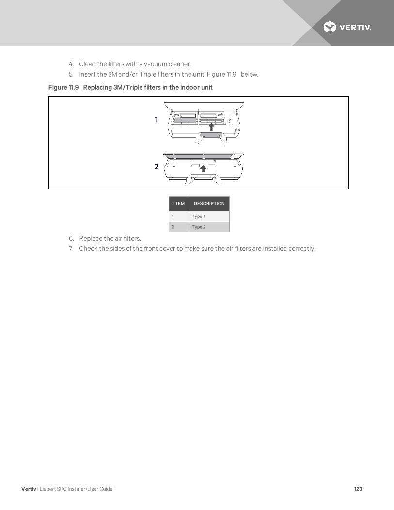
4. Clean the filters with a vacuum cleaner.
5. Insert the 3M and/or Triple filters in the unit, Figure 11.9 below.
Figure 11.9 Replacing 3M/Triple filters in the indoor unit
ITEM DESCRIPTION
1 Type 1
2 Type 2
6. Replace the air filters.
7. Check the sides of the front cover to make sure the air filters are installed correctly.
Vertiv | Liebert SRC Installer/User Guide | 123

Vertiv | Liebert SRC Installer/User Guide | 124
This page intentionally left blank.
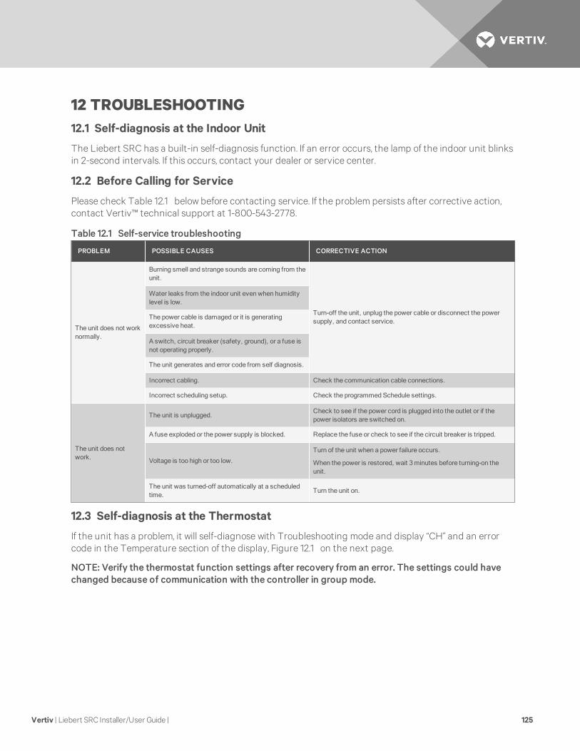
12 TROUBLESHOOTING12.1 Self-diagnosis at the Indoor Unit
The Liebert SRC has a built-in self-diagnosis function. If an error occurs, the lamp of the indoor unit blinksin 2-second intervals. If this occurs, contact your dealer or service center.
12.2 Before Calling for Service
Please check Table 12.1 below before contacting service. If the problem persists after corrective action,contact Vertiv™ technical support at 1-800-543-2778.
PROBLEM POSSIBLE CAUSES CORRECTIVE ACTION
The unit does not worknormally.
Burning smell and strange sounds are coming from theunit.
Turn-off the unit, unplug the power cable or disconnect the powersupply, and contact service.
Water leaks from the indoor unit even when humiditylevel is low.
The power cable is damaged or it is generatingexcessive heat.
A switch, circuit breaker (safety, ground), or a fuse isnot operating properly.
The unit generates and error code from self diagnosis.
Incorrect cabling. Check the communication cable connections.
Incorrect scheduling setup. Check the programmed Schedule settings.
The unit does notwork.
The unit is unplugged.Check to see if the power cord is plugged into the outlet or if thepower isolators are switched on.
A fuse exploded or the power supply is blocked. Replace the fuse or check to see if the circuit breaker is tripped.
Voltage is too high or too low.
Turn of the unit when a power failure occurs.
When the power is restored, wait 3 minutes before turning-on theunit.
The unit was turned-off automatically at a scheduledtime.
Turn the unit on.
Table 12.1 Self-service troubleshooting
12.3 Self-diagnosis at the Thermostat
If the unit has a problem, it will self-diagnose with Troubleshooting mode and display “CH” and an errorcode in the Temperature section of the display, Figure 12.1 on the next page.
NOTE: Verify the thermostat function settings after recovery from an error. The settings could havechanged because of communication with the controller in group mode.
Vertiv | Liebert SRC Installer/User Guide | 125

Figure 12.1 Error codes displayed at the thermostat
12.4 Troubleshooting Error Codes at the Indoor and Outdoor Units
Table 12.2 on the facing page, lists the most-common error codes that you will see on these units. Somemodels may display codes not listed here. Please contact service if a power-down/reboot does not correctthe issue. Do not attempt to fix the unit yourself.
The error codes indicate different types of failures, assist in self-diagnosis, and helps track frequency ofoccurrence. Figure 12.2 below and Figure 12.3 on the facing page show where error codes display basedon model number.
If two or more errors occur simultaneously, the lower number displays first. When an error is resolved, thenumber no longer displays.
12.4.1 Decoding Error Display for SRC18
Refer to Figure 12.2 below.
• LED 1 blinks (green) to indicate the second, “ones” digit of the error code.
• LED 2 blinks (red) to indicate the first, “tens” digit of the error code.
For example, if the error code is 21, LED 1 blinks 1 time, and LED 2 blinks 2 times.
Figure 12.2 Error-code display for SRC18
ITEM DESCRIPTION
1 LED 1 (“ones” digit)
2 LED 2 (“tens” digit)
Vertiv | Liebert SRC Installer/User Guide | 126

Decoding Error Display for SRC24 and SRC36
Refer to Figure 12.3 below.
• The digital display blinks “CH” then the error number.
Figure 12.3 Error-code display for SRC24 and SRC36
UNITERROR
NO.DESCRIPTION
INDOOR UNITLED
SRC18 LED BLINKS
SRC24 AND SRC36DISPLAYSLED 1
(2NDDIGIT)
LED 2(1ST
DIGIT)
Indoor
1 Indoor unit room-temperature sensor error ü 1x — CH01
2 Indoor unit inlet pipe sensor error ü 2x — CH02
3 Wired remote-control error ü 3x — CH03
4 Float switch (optional) error ü 4x — CH04
5Communication error between indoor and
outdoor unitü 5x — CH05
6 Indoor unit outlet-pipe sensor error ü 6x — CH06
9 Indoor unit EEPROM error ü 9x — CH09
10 Indoor unit BLDC motor fan lock ü — 1x CH10
12 Indoor unit middle pipe sensor error ü 2x 1x CH12
Table 12.2 SRC Error Codes
Vertiv | Liebert SRC Installer/User Guide | 127

UNITERROR
NO.DESCRIPTION
INDOOR UNITLED
SRC18 LED BLINKS
SRC24 AND SRC36DISPLAYSLED 1
(2NDDIGIT)
LED 2(1ST
DIGIT)
Outdoor
21 DC Peak (IPM fault) ü 1x 2x CH21
22 CT 2 (Max CT) ü 2x 2x CH22
23 DC Link Low/High Volt ü 3x 2x CH23
26 DC CompPosition Error ü 6x 2x CH26
27 PSC Fault ü 7x 2x CH27
29 CompPhaseOver-current ü 9x 2x CH29
32 Invert Compressor D-pipe Overheat ü 2x 3x CH32
38 Refrigerant Leak detection ü 8x 3x CH38
37 Exceed the Compression Ration Limit ü 7x 3x CH37
41 D-pipe Sensor Error ü 1x 4x CH41
44 Outdoor Air Sensor Error ü 4x 4x CH44
45 Cond. Out Pipe High ü 8x 4x CH45
51Excess Capacity (Mismatching between
In/Outdoor unit)ü 1x 5x CH51
53 Communication Error (IN-OUT) ü 3x 5x CH53
60 Outdoor EEPROM Check sum error ü — 6x CH60
61 Cond. Pipe High ü 1x 6x CH61
62 Heat Sink Sensor Temp. High ü 2x 6x CH62
65 Heat sink Th Error (open/short) ü 5x 6x CH65
67 BLDC Motor Fan Lock ü 7x 6x CH67
72 Detect 4Way Valve Transfer Failure ü 2x 7x CH72
93 Communication Error (IN-OUT) ü 3x 9x CH93
Table 12.2 SRC Error Codes (continued)
12.5 Troubleshooting Table
Table 12.3 on the facing page lists problems, possible causes, and a corrective action.
Vertiv | Liebert SRC Installer/User Guide | 128

PROBLEM POSSIBLE CAUSES CORRECTIVE ACTION
Unit does not emit cool air
Air is not circulating properly.Make sure that there are not curtains, blinds, or furniture blocking thefront of the unit.
The air filter is dirty.Clean the air filter once every 2 weeks. See Cleaning the Air Filter onpage 120.
The room temperature is too high.In summer, cooling the indoor air fully may take some time. In thiscase, select Power Cool to cool the indoor air quickly.
Cold air is escaping from the room.Make sure that no cold air is escaping through ventilation points in theroom.
The desired temperature is higher than the settemperature.
Set the desired temperature to a level lower than the currenttemperature.
There is a heating source nearby.Avoid using heat generators like electric ovens or gas burners while theunit is operating.
FanMode is selected.
During fanmode, air blows from the unit without cooling or heating theindoor air.
Switch the operationmode to cooling.
Outside temperature is too high. The cooling effect may not be sufficient.
The fan speed cannot beadjusted.
The Jet Mode or Auto OperationMode isselected.
In some operationmodes, you cannot adjust the fan speed. Select anoperationmode in which you can adjust the fan speed.
The temperature cannot beadjusted.
The FanMode or Jet Mode is selected.In some operationmodes, you cannot adjust the temperature. Select anoperationmode in which you can adjust the temperature.
The unit stops duringoperation.
The unit is suddenly turned off.The Timer Functionmay have timed-out, which turns the unit off.Check the timer/schedule settings.
A power failure has occurred during operation.Wat for the power to come back. If you have the Auto Restart functionenabled, your unit will resume in its last operationmode several minutesafter power is restored.
The indoor unit is stilloperating even when thepower has been turned off.
The Auto Clean function is being operated.All the Auto Clean function to continue because it removes anyremainingmoisture inside the indoor unit. If you do not want it tocontinue, turn the unit off.
The air outlet on the indoorunit is dischargingmist.
The cooled air from the unit makes mist.When the room temperature decreases, the phenomenon willdisappear.
Water leaks from theoutdoor unit.
In heating operation, condensed water dropsfrom the heat exchanger.
This requires installing a drain hose under the base pan. Contact theinstaller.
Table 12.3 Troubleshooting problems, causes and correction
Vertiv | Liebert SRC Installer/User Guide | 129

PROBLEM POSSIBLE CAUSES CORRECTIVE ACTION
There is a noise or vibration.
A clicking sound cab be hard when the unitstarts or stops due tomovement of thereversing valve.Creaking sound: The plastic parts of theindoor unit creak due to sudden temperaturechanges.Flowing or Blowing sound: This is the flow ofthe refrigerant through the unit.
These are normal occurrences. The noise will stop.
The indoor unit gives off anodor.
Odors (such as cigarette smoke) may beabsorbed into the indoor unit and dischargedwith air flow.
If the smell does not disappear, wash the air filter. If this does not work,contact service to clean the heat exchanger.
The unit does not emitwarm air.
When HeatingMode starts, the vane isalmost closed and no air comes out, eventhought the outdoor unit is operating.
This is normal. Please wait until the unit has generated enough warm airto blow through the indoor unit.
The outdoor unit is in DefrostingMode.In HeatingMode, ice/frost builds up on the coils when the outsidetemperature falls. This function removes the layer of frost on the coiland should finish in approximately 15 minutes.
Outside temperature is too low. The heating effect may not be sufficient.
Depending onmode, some functions may not be supported.
Table 12.3 Troubleshooting problems, causes and correction (continued)
12.6 Refrigerant Leaks
CAUTION: Risk of exposure to excessive refrigerant concentration and oxygen depletion. Cancause illness or injury. If the unit is installed in a small improperly or non-ventilated space, takemeasures to prevent the refrigerant concentration from exceeding safety limits in the event of arefrigerant leak. Verify the maximum refrigerant concentration level in the space where theindoor unit will be mounted meets the concentration limit for the application.
NOTE: Take appropriate actions at the end of HVAC equipment life to recover, recycle, reclaim ordestroy R410A refrigerant according to applicable US EPA rules.
ASHRAE Standards 15-2010 and 34-2010 offer guidelines that address refrigerant safety and themaximum allowable concentration of refrigerant in an occupied space. Refrigerant will dissipate into theatmosphere, but a certain volume of air is required for this to occur safely. For R410A refrigerant, themaximum allowable concentration is 0.026 lbs/ft3 per 1,000 ft3 of air in an occupied space. Buildings with24-hour occupancy allow half of that concentration.1
ASHRAE Standards 15 and 34 assume that if a system develops a leak, its entire refrigerant charge willdump into the area where the leak occurs. To meet ASHRAE Standards 15 and 34, calculate therefrigerant concentration that may occur in the smallest room volume on the system, and compare theresults to the maximum allowable concentration number.1 Also consult state and local codes with regardto refrigerant safety.
To calculate the potential refrigerant concentration level (RCL):
1. Measure the occupied space dimensions (in feet).
2. Calculate the cubic foot volume of air in the smallest occupied space. (To obtain a detailedoverview of the RCL, perform the same calculations to the second smallest zone, the thirdsmallest zone until the RCL is obtained for all zones. Also, pay special attention to areas such asbasements, etc., where refrigerant cannot dissipate easily.)
Vertiv | Liebert SRC Installer/User Guide | 130
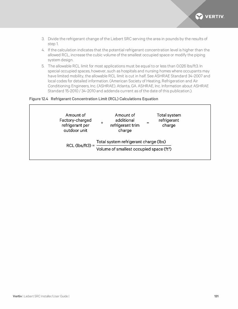
3. Divide the refrigerant change of the Liebert SRC serving the area in pounds by the results ofstep 1.
4. If the calculation indicates that the potential refrigerant concentration level is higher than theallowed RCL, increase the cubic volume of the smallest occupied space or modify the pipingsystem design.
5. The allowable RCL limit for most applications must be equal to or less than 0.026 lbs/ft3. Inspecial occupied spaces, however, such as hospitals and nursing homes where occupants mayhave limited mobility, the allowable RCL limit is cut in half. See ASHRAE Standard 34-2007 andlocal codes for detailed information. (American Society of Heating, Refrigeration and AirConditioning Engineers, Inc. (ASHRAE). Atlanta, GA. ASHRAE, Inc. Information about ASHRAEStandard 15-2010 / 34-2010 and addenda current as of the date of this publication.).
Figure 12.4 Refrigerant Concentration Limit (RCL) Calculations Equation
Vertiv | Liebert SRC Installer/User Guide | 131

Vertiv | Liebert SRC Installer/User Guide | 132
This page intentionally left blank.

APPENDICES
Appendix A: Technical Support and Contacts
A.1 Technical Support/Service in the United States
Vertiv Services, Inc.
24x7 dispatch of technicians for all products.
1-800-543-2378
Liebert Thermal Management Products
1-800-543-2778
Liebert Channel Products
1-800-222-5877
Liebert AC and DC Power Products
1-800-543-2378
A.2 Locations
United States
Vertiv Headquarters
1050 Dearborn Drive
Columbus, OH, 43085, USA
Europe
Via Leonardo Da Vinci 8 Zona Industriale Tognana
35028 Piove Di Sacco (PD) Italy
+39 049 9719 111
Fax: +39 049 5841 257
Asia
7/F, Dah Sing Financial Centre
3108 Gloucester Road, Wanchai
Hong Kong 852 2572220
Fax: 852 28029250
Vertiv | Liebert SRC Installer/User Guide | 133

Vertiv | Liebert SRC Installer/User Guide | 134
This page intentionally left blank.


VertivCo.com | Vertiv Headquarters, 1050 Dearborn Drive, Columbus, OH, 43085, USA
© 2017VertivCo. All rights reserved. Vertiv and the Vertiv logo are trademarks or registered trademarks of VertivCo. All other names and logos referred toare trade names, trademarks or registered trademarks of their respective owners. While everyprecaution has been taken to ensure accuracyandcompleteness herein, VertivCo. assumes no responsibility, and disclaims all liability, for damages resulting from use of this information or for anyerrors oromissions. Specifications are subject to change without notice.
SL-11055_REV3_9-17/590-1630-501A