Embed Size (px)
Citation preview
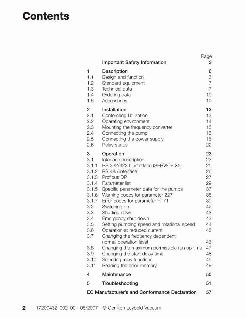
Part Numbers
800072Vxxxx
TURBO.DRIVE 300Frequency Converter for Turbomolecular Pumps
Operating Instructions 17200432_002_00Valid from Firmware 1.13
Important Safety Information 3
1 Description 61.1 Design and function 61.2 Standard equipment 71.3 Technical data 71.4 Ordering data 101.5 Accessories 10
2 Installation 132.1 Conforming Utilization 132.2 Operating environment 142.3 Mounting the frequency converter 152.4 Connecting the pump 162.5 Connecting the power supply 162.6 Relay status 22
3 Operation 233.1 Interface description 233.1.1 RS 232/422 C interface (SERVICE X5) 253.1.2 RS 485 interface 263.1.3 Profibus DP 273.1.4 Parameter list 293.1.5 Specific parameter data for the pumps 373.1.6 Warning codes for parameter 227 383.1.7 Error codes for parameter P171 393.2 Switching on 423.3 Shutting down 433.4 Emergency shut down 433.5 Setting pumping speed and rotational speed 443.6 Operation at reduced current 453.7 Changing the frequency dependent
normal operation level 463.8 Changing the maximum permissible run up time 473.9 Changing the start delay time 483.10 Selecting relay functions 493.11 Reading the error memory 49
4 Maintenance 50
5 Troubleshooting 51
EC Manufacturer’s and Conformance Declaration 57
Contents
2 17200432_002_00 - 05/2007 - © Oerlikon Leybold Vacuum
Page
Important Safety Information
Indicates procedures that must be strictly observed to pre-vent hazards to persons.
Indicates procedures that must be strictly observed to pre-vent damage to, or destruction of the product.
The Oerlikon Leybold Vacuum TURBO.DRIVE 300 havebeen designed for safe and efficient operation whenused properly and in accordance with these OperatingInstructions. It is the responsibility of the user to careful-ly read and strictly observe all safety precautions de-scribed in this section and throughout the OperatingInstructions. The TURBO.DRIVE must only be oper-ated in the proper condition and under the conditi-ons described in the Operating Instructions. It mustbe operated and maintained by trained personnel only.Consult local, state, and national agencies regardingspecific requirements and regulations. Address anyfurther safety, operation and/or maintenance questionsto our nearest office.
Safety Information
317200432_002_00 - 05/2007 - © Oerlikon Leybold Vacuum
Warning
Caution
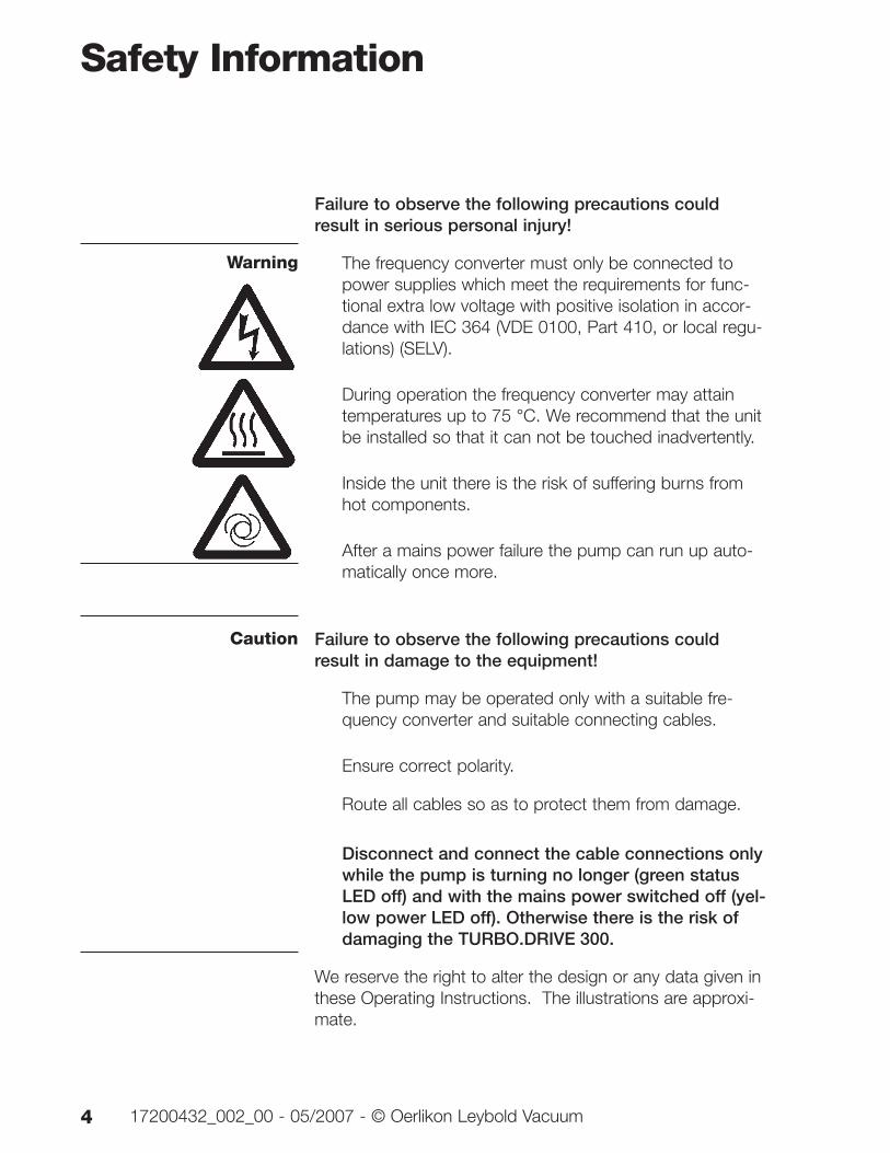
Failure to observe the following precautions couldresult in serious personal injury!
The frequency converter must only be connected topower supplies which meet the requirements for func-tional extra low voltage with positive isolation in accor-dance with IEC 364 (VDE 0100, Part 410, or local regu-lations) (SELV).
During operation the frequency converter may attaintemperatures up to 75 °C. We recommend that the unitbe installed so that it can not be touched inadvertently.
Inside the unit there is the risk of suffering burns fromhot components.
After a mains power failure the pump can run up auto-matically once more.
Failure to observe the following precautions couldresult in damage to the equipment!
The pump may be operated only with a suitable fre-quency converter and suitable connecting cables.
Ensure correct polarity.
Route all cables so as to protect them from damage.
Disconnect and connect the cable connections onlywhile the pump is turning no longer (green statusLED off) and with the mains power switched off (yel-low power LED off). Otherwise there is the risk ofdamaging the TURBO.DRIVE 300.
We reserve the right to alter the design or any data given inthese Operating Instructions. The illustrations are approxi-mate.
Safety Information
4 17200432_002_00 - 05/2007 - © Oerlikon Leybold Vacuum
Warning
Caution
Description
517200432_002_00 - 05/2007 - © Oerlikon Leybold Vacuum
REMOTE (X1)
ERRPWRSTS
TURBO.DRIVE 300
HEAT SINK
HEAT
SIN
K
SERVICE (X5)
DRIVE (X3) 24 V(X4)
HEAT
SIN
K
HEAT SINK
Pump
connection
Supply voltage
connection male 24 V
Cooling surfaces
9 pin Sub-D connector
female for RS 232 interface
LEDs
REMOTE connector
9 pin Sub-D (female)
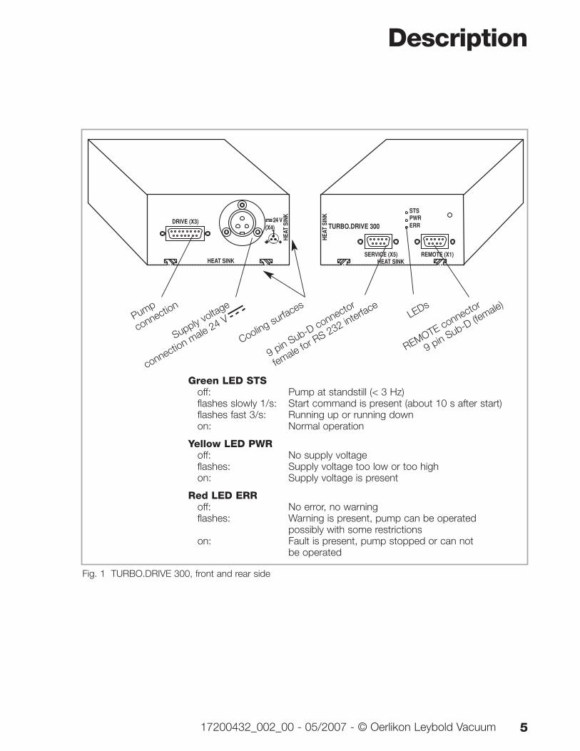
Fig. 1 TURBO.DRIVE 300, front and rear side
Green LED STSoff: Pump at standstill (< 3 Hz)flashes slowly 1/s: Start command is present (about 10 s after start)flashes fast 3/s: Running up or running downon: Normal operation
Yellow LED PWRoff: No supply voltageflashes: Supply voltage too low or too highon: Supply voltage is present
Red LED ERRoff: No error, no warningflashes: Warning is present, pump can be operated
possibly with some restrictionson: Fault is present, pump stopped or can not
be operated
Description
6 17200432_002_00 - 05/2007 - © Oerlikon Leybold Vacuum
HEAT SINK
HEAT
SIN
K
TurboDrive 300
SERVICE (X5) REMOTE (X1)
STS
PWRERR
PROFIBUS
BUS STSBUS ERR
HIGH LOWFEDC
BA
9 8 7 6 5 432
1
FEDC
BA
9 8 7 6 5 432
1
Profibus LEDs
9-way Profibus
connection
Selector switches fo
r set-
ting the Profibus address
in
the hexadecimal format
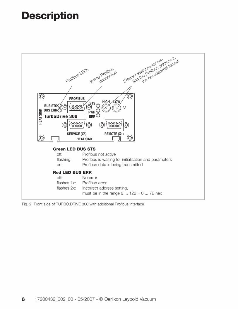
Green LED BUS STSoff: Profibus not activeflashing: Profibus is waiting for initialisation and parameterson: Profibus data is being transmitted
Red LED BUS ERRoff: No errorflashes 1x: Profibus errorflashes 2x: Incorrect address setting,
must be in the range 0 ... 126 = 0 ... 7E hex
Fig. 2 Front side of TURBO.DRIVE 300 with additional Profibus interface
1 Description
1.1 Design and functionThe TURBO.DRIVE 300 supplies power to the TW seriesturbomolecular pumps and is used to control their opera-tion.
The TURBO.DRIVE 300 is either integrated in the pump orit is separate and linked to the pump by means of aconnecting cable.
The TURBO.DRIVE 300 requires a supply voltage of 24 VDC. It is equipped with interfaces for programmable con-trols (REMOTE) and an optional interface for serial commu-nication.
1.2 Standard equipmentIncluded with the delivery are the DC connector HiroseHS16P-3, four moving nuts M4 for affixing the frequencyconverter and the Operating Instructions.
Description
717200432_002_00 - 05/2007 - © Oerlikon Leybold Vacuum
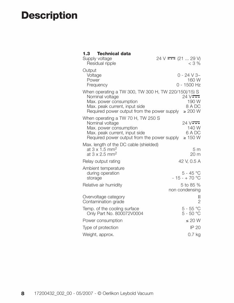
1.3 Technical dataSupply voltage 24 V (21 ... 29 V)
Residual ripple < 3 %
OutputVoltage 0 - 24 V 3~Power 160 WFrequency 0 - 1500 Hz
When operating a TW 300, TW 300 H, TW 220/150(/15) SNominal voltage 24 VMax. power consumption 190 WMax. peak current, input side 8 A DCRequired power output from the power supply ≥ 200 W
When operating a TW 70 H, TW 250 SNominal voltage 24 VMax. power consumption 140 WMax. peak current, input side 6 A DCRequired power output from the power supply ≥ 150 W
Max. length of the DC cable (shielded)at 3 x 1.5 mm2 5 mat 3 x 2.5 mm2 20 m
Relay output rating 42 V, 0.5 A
Ambient temperature during operation 5 - 45 °Cstorage - 15 - + 70 °C
Relative air humidity 5 to 85 % non condensing
Overvoltage category IIContamination grade 2
Temp. of the cooling surface 5 - 55 °COnly Part No. 800072V0004 5 - 50 °C
Power consumption ≤ 20 W
Type of protection IP 20
Weight, approx. 0.7 kg
Description
8 17200432_002_00 - 05/2007 - © Oerlikon Leybold Vacuum
Description
917200432_002_00 - 05/2007 - © Oerlikon Leybold Vacuum
3373,2
100
18,1 63,8
DRIVE (X3) 24 V(X4)
REMOTE (X1)
ERR
PWR
STS
TURBO.DRIVE 300
HEAT SINK
HEA
T SI
NK
SERVICE (X5) 16,85
40,779,7
100
50
HEA
T SI
NK
HEAT SINK
22,2 29,3
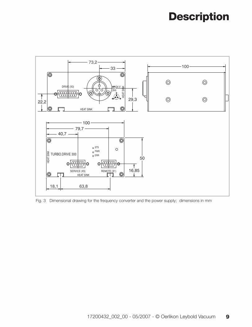
Fig. 3 Dimensional drawing for the frequency converter and the power supply; dimensions in mm
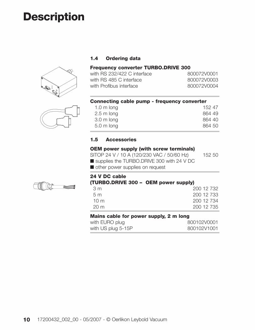
1.4 Ordering data
Frequency converter TURBO.DRIVE 300with RS 232/422 C interface 800072V0001with RS 485 C interface 800072V0003with Profibus interface 800072V0004
Connecting cable pump - frequency converter 1.0 m long 152 472.5 m long 864 493.0 m long 864 405.0 m long 864 50
1.5 Accessories
OEM power supply (with screw terminals)SITOP 24 V / 10 A (120/230 VAC / 50/60 Hz) 152 50■ supplies the TURBO.DRIVE 300 with 24 V DC■ other power supplies on request
24 V DC cable (TURBO.DRIVE 300 – OEM power supply)
3 m 200 12 7325 m 200 12 73310 m 200 12 73420 m 200 12 735
Mains cable for power supply, 2 m longwith EURO plug 800102V0001with US plug 5-15P 800102V1001
Description
10 17200432_002_00 - 05/2007 - © Oerlikon Leybold Vacuum
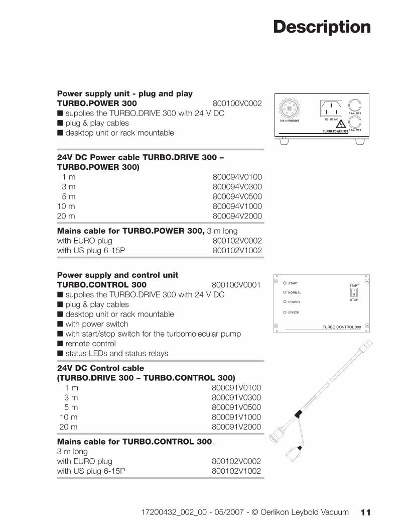
Power supply unit - plug and play TURBO.POWER 300 800100V0002■ supplies the TURBO.DRIVE 300 with 24 V DC■ plug & play cables■ desktop unit or rack mountable
24V DC Power cable TURBO.DRIVE 300 –TURBO.POWER 300)
1 m 800094V01003 m 800094V03005 m 800094V0500
10 m 800094V100020 m 800094V2000
Mains cable for TURBO.POWER 300, 3 m longwith EURO plug 800102V0002with US plug 6-15P 800102V1002
Power supply and control unit TURBO.CONTROL 300 800100V0001■ supplies the TURBO.DRIVE 300 with 24 V DC■ plug & play cables■ desktop unit or rack mountable■ with power switch■ with start/stop switch for the turbomolecular pump■ remote control■ status LEDs and status relays
24V DC Control cable(TURBO.DRIVE 300 – TURBO.CONTROL 300)
1 m 800091V01003 m 800091V03005 m 800091V0500
10 m 800091V100020 m 800091V2000
Mains cable for TURBO.CONTROL 300,3 m longwith EURO plug 800102V0002with US plug 6-15P 800102V1002
Description
1117200432_002_00 - 05/2007 - © Oerlikon Leybold Vacuum
TURBO.POWER 300
T 5 A ~ 250 V
T 5 A ~ 250 V
100 - 240 V AC
START
NORMAL
POWER
ERROR
START
STOP
TURBO.CONTROL 300
10
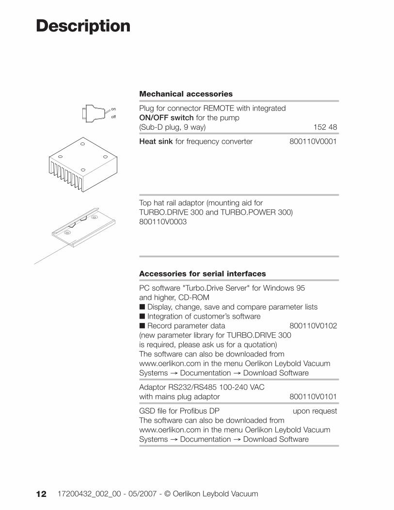
Mechanical accessories
Plug for connector REMOTE with integrated ON/OFF switch for the pump (Sub-D plug, 9 way) 152 48
Heat sink for frequency converter 800110V0001
Top hat rail adaptor (mounting aid forTURBO.DRIVE 300 and TURBO.POWER 300)800110V0003
Accessories for serial interfaces
PC software "Turbo.Drive Server" for Windows 95 and higher, CD-ROM■ Display, change, save and compare parameter lists■ Integration of customer’s software■ Record parameter data 800110V0102(new parameter library for TURBO.DRIVE 300is required, please ask us for a quotation)The software can also be downloaded from www.oerlikon.com in the menu Oerlikon Leybold VacuumSystems → Documentation → Download Software
Adaptor RS232/RS485 100-240 VACwith mains plug adaptor 800110V0101
GSD file for Profibus DP upon requestThe software can also be downloaded from www.oerlikon.com in the menu Oerlikon Leybold VacuumSystems → Documentation → Download Software
Description
12 17200432_002_00 - 05/2007 - © Oerlikon Leybold Vacuum
on
off
2 Installation
2.1 Conforming UtilizationThe TURBO.DRIVE 300 supplies power to the TW seriesturbomolecular pumps and is used to control their opera-tion.
The TURBO.DRIVE 300 is suited for operation of the follo-wing pumps:
■ TURBOVAC TW 70 H
■ TURBOVAC TW 220/150 S, TW 220/150/15 S
■ TURBOVAC TW 250 S
■ TURBOVAC TW 290 H
■ TURBOVAC TW 300, TW 300 H
Other pumps may only be operated after approval fromOerlikon Leybold Vacuum or if the operation of such pumpsis expressly permitted in the Operating Instructions for thespecific pump.
The TURBO.DRIVE may only be operated with powersupply units which meet SELV (Safety Extra Low Voltage)requirements.
The TURBO.DRIVE must only be opened by certifiedOerlikon Leybold Vacuum Service Centres. Opening byunauthorised personnel voids warranty.
Installation
1317200432_002_00 - 05/2007 - © Oerlikon Leybold Vacuum
2.2 Operating environmentSee also Chapter 1.3 Technical Data.
Places of installation up to 1000 m above sea level (3300 ft)are possible without restrictions. At altitudes over 1000 mheat dissipation by the ambient air is impaired. Please con-sult us.
If the TURBO.DRIVE 300 has been integrated in the pump,it is cooled by the pump.
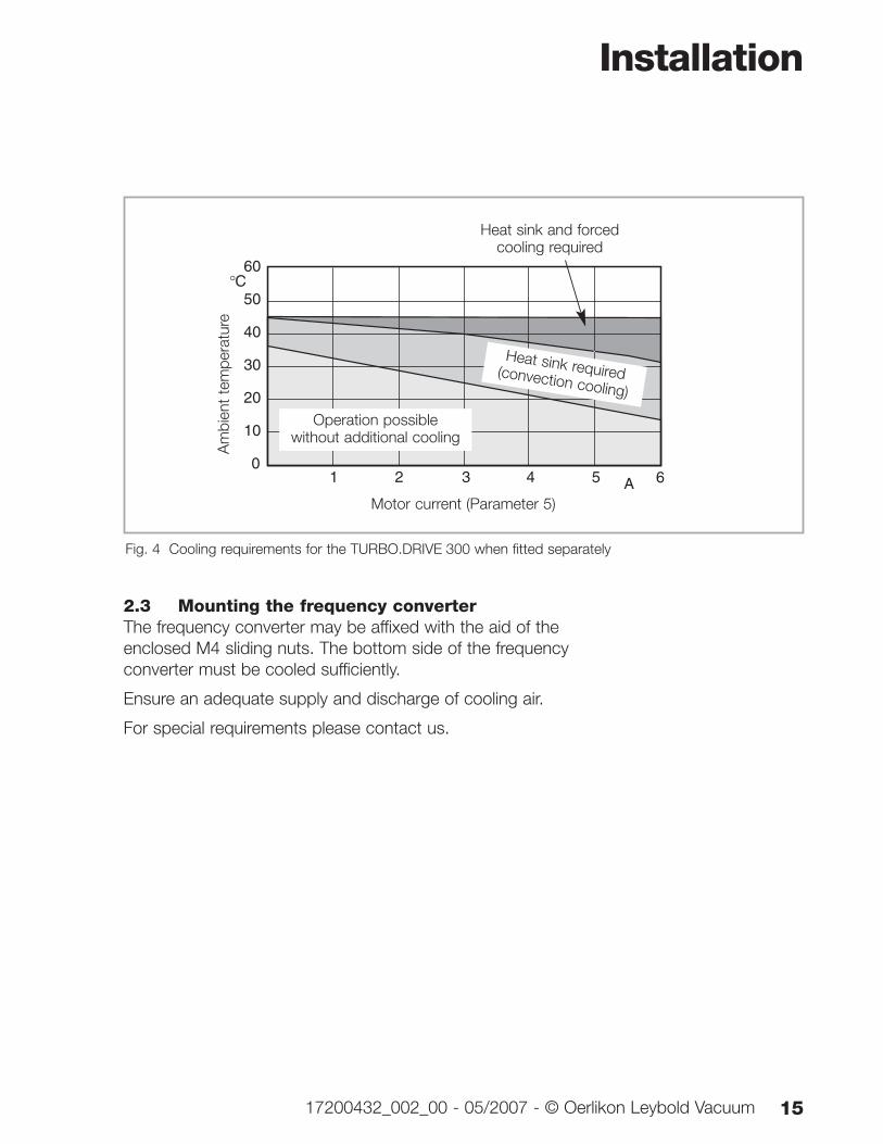
As to the cooling requirements for the separately fittedTURBO. DRIVE see Fig. 4. The bottom side of the frequen-cy converter must not be allowed to attain temperatures inexcess of 55 °C, in the case of frequency converters equip-ped with a Profibus interface the temperature at the bottommust not exceed 50 °C.
Max. magnetic induction levels are 15 mT, max. radioactiveradiation spec. is 105 rad (103 Gy).
The frequency converter must only be used in rooms withinbuildings. It must not be operated in explosive gas atmo-spheres.
The frequency converter and the connecting lines must beprotected against exposure to sprayed and condensingwater.
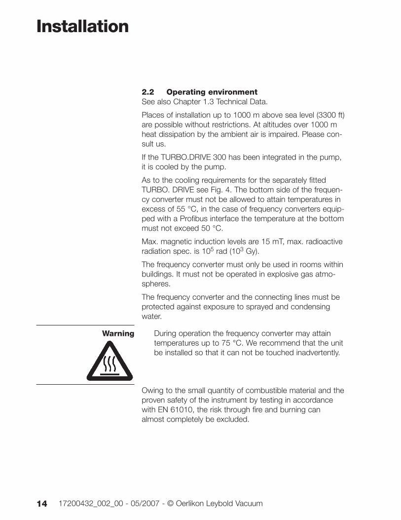
During operation the frequency converter may attaintemperatures up to 75 °C. We recommend that the unitbe installed so that it can not be touched inadvertently.
Owing to the small quantity of combustible material and theproven safety of the instrument by testing in accordancewith EN 61010, the risk through fire and burning canalmost completely be excluded.
Installation
14 17200432_002_00 - 05/2007 - © Oerlikon Leybold Vacuum
Warning
2.3 Mounting the frequency converterThe frequency converter may be affixed with the aid of theenclosed M4 sliding nuts. The bottom side of the frequencyconverter must be cooled sufficiently.
Ensure an adequate supply and discharge of cooling air.
For special requirements please contact us.
Installation
1517200432_002_00 - 05/2007 - © Oerlikon Leybold Vacuum
1 2 3 4 5 A
60
50
40
30
20
10
0
C
6
Fig. 4 Cooling requirements for the TURBO.DRIVE 300 when fitted separately
Motor current (Parameter 5)
Am
bien
t te
mpe
ratu
re
Operation possible without additional cooling
Heat sink required(convection cooling)
Heat sink and forced cooling required
Installation
16 17200432_002_00 - 05/2007 - © Oerlikon Leybold Vacuum
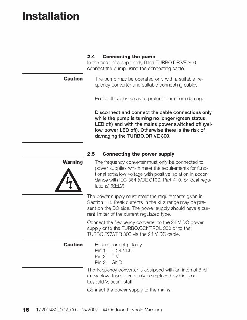
2.4 Connecting the pumpIn the case of a separately fitted TURBO.DRIVE 300connect the pump using the connecting cable.
The pump may be operated only with a suitable fre-quency converter and suitable connecting cables.
Route all cables so as to protect them from damage.
Disconnect and connect the cable connections onlywhile the pump is turning no longer (green statusLED off) and with the mains power switched off (yel-low power LED off). Otherwise there is the risk ofdamaging the TURBO.DRIVE 300.
2.5 Connecting the power supply
The frequency converter must only be connected topower supplies which meet the requirements for func-tional extra low voltage with positive isolation in accor-dance with IEC 364 (VDE 0100, Part 410, or local regu-lations) (SELV).
The power supply must meet the requirements given inSection 1.3. Peak currents in the kHz range may be pre-sent on the DC side. The power supply should have a cur-rent limiter of the current regulated type.
Connect the frequency converter to the 24 V DC powersupply or to the TURBO.CONTROL 300 or to theTURBO.POWER 300 via the 24 V DC cable.
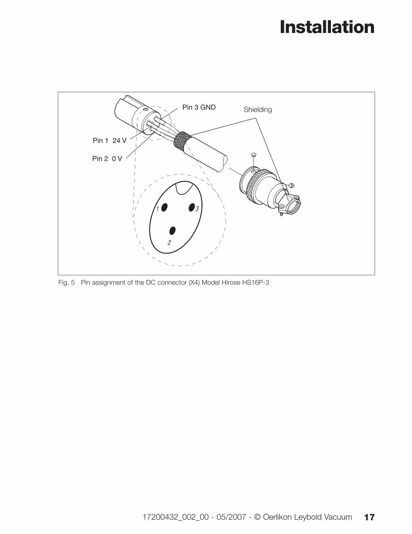
Ensure correct polarity.Pin 1 + 24 VDCPin 2 0 VPin 3 GND
The frequency converter is equipped with an internal 8 AT(slow blow) fuse. It can only be replaced by OerlikonLeybold Vacuum staff.
Connect the power supply to the mains.
Caution
Warning
Caution
Installation
1717200432_002_00 - 05/2007 - © Oerlikon Leybold Vacuum
1
2
3
Pin 1 24 V
Pin 2 0 V
Pin 3 GND Shielding
Fig. 5 Pin assignment of the DC connector (X4) Model Hirose HS16P-3
Installation
18 17200432_002_00 - 05/2007 - © Oerlikon Leybold Vacuum
RE
MO
TE
93 -
132
/18
7 -
264
V A
C,
50/6
0 H
z
24 V
DC
L1 N PE
120
V
AC L+ M M
+ 2
4 V
DC
0 V
DC
GN
D
LED
PO
WE
R
DR
IVE
(X3)
DC
24
V(X
4)
HEAT SINK
HEA
T SI
NK
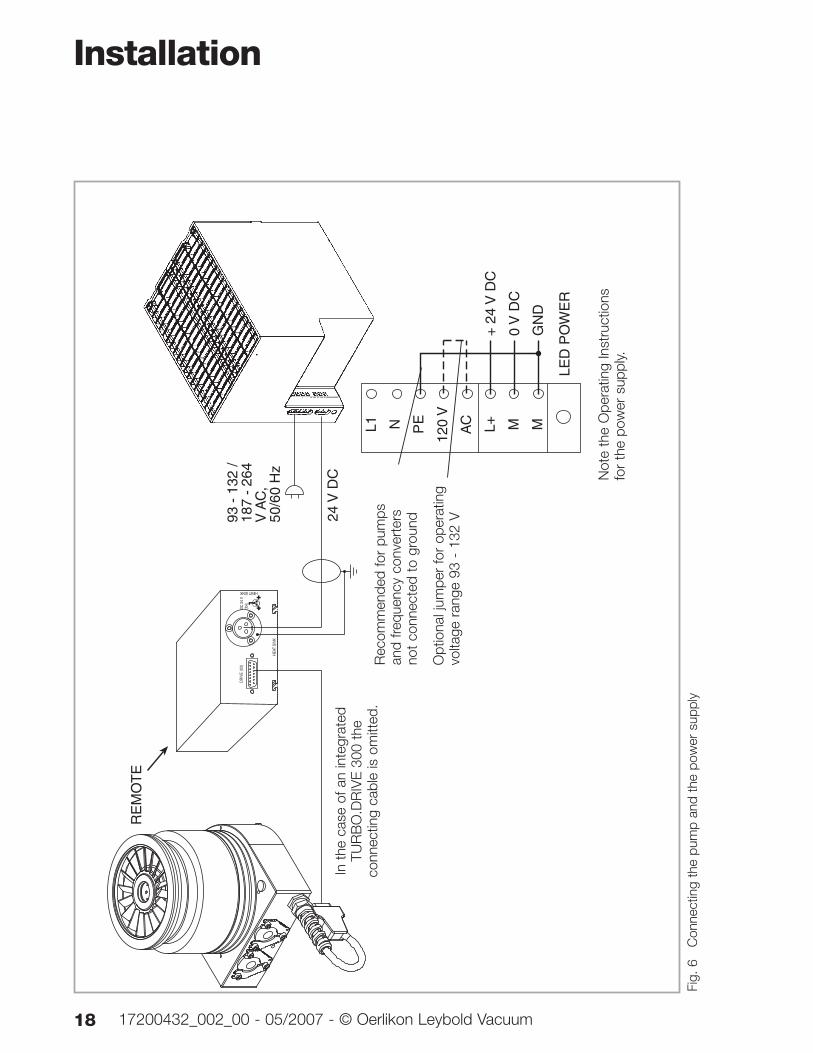
Fig.
6
Con
nect
ing
the
pum
p an
d th
e po
wer
sup
ply
Opt
iona
l jum
per
for
oper
atin
gvo
ltage
ran
ge 9
3 -
132
V
Not
e th
e O
pera
ting
Inst
ruct
ions
for
the
pow
er s
uppl
y.
In t
he c
ase
of a
n in
tegr
ated
TUR
BO
.DR
IVE
300
the
conn
ectin
g ca
ble
is o
mitt
ed.
Rec
omm
ende
d fo
r pu
mps
an
d fre
quen
cy c
onve
rter
s no
t co
nnec
ted
to g
roun
d
Installation
1917200432_002_00 - 05/2007 - © Oerlikon Leybold Vacuum
RE
MO
TE
IN
RE
MO
TE
FR
ON
T
MA
INS
ON
100 - 240 V ~
24 V
PO
WE
R O
UT
RE
MO
TE
OU
TT
5 A
25
0 V
~
1 0
1 0O
FF
T5
A25
0 V
~
RE
MO
TE
DR
IVE
(X3)
DC
24
V(X
4)
HEAT SINK
HEA
T SI
NK
100
- 24
0 V
~
50 -
60
Hz
24 V
DC C
ontro
l cab
le
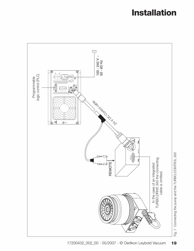
In t
he c
ase
of a
n in
tegr
ated
TUR
BO
.DR
IVE
300
the
conn
ectin
gca
ble
is o
mitt
ed.
Fig.
7
Con
nect
ing
the
pum
p an
d th
e TU
RB
O.C
ON
TRO
L 30
0
Pro
gram
mab
le
logi
c co
ntro
l (P
LC)
Installation
20 17200432_002_00 - 05/2007 - © Oerlikon Leybold Vacuum
TURB
O.PO
WER
300
T 5
A ~
250
V
T 5
A ~
250
V
100
- 240
V A
C
DR
IVE
(X3)
DC
24
V(X
4)
HEAT SINK
HEA
T SI
NK
100
- 24
0 V
AC
50
/60
Hz
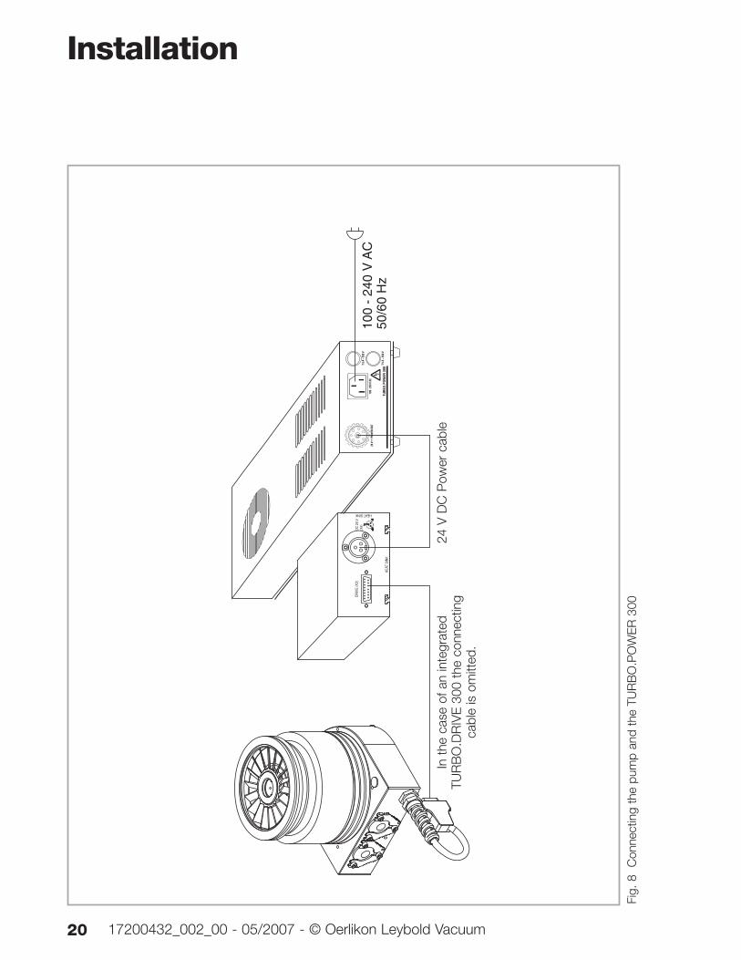
In t
he c
ase
of a
n in
tegr
ated
TUR
BO
.DR
IVE
300
the
conn
ectin
gca
ble
is o
mitt
ed.
Fig.
8
Con
nect
ing
the
pum
p an
d th
e TU
RB
O.P
OW
ER
300
24 V
DC
Pow
er c
able
Installation
2117200432_002_00 - 05/2007 - © Oerlikon Leybold Vacuum
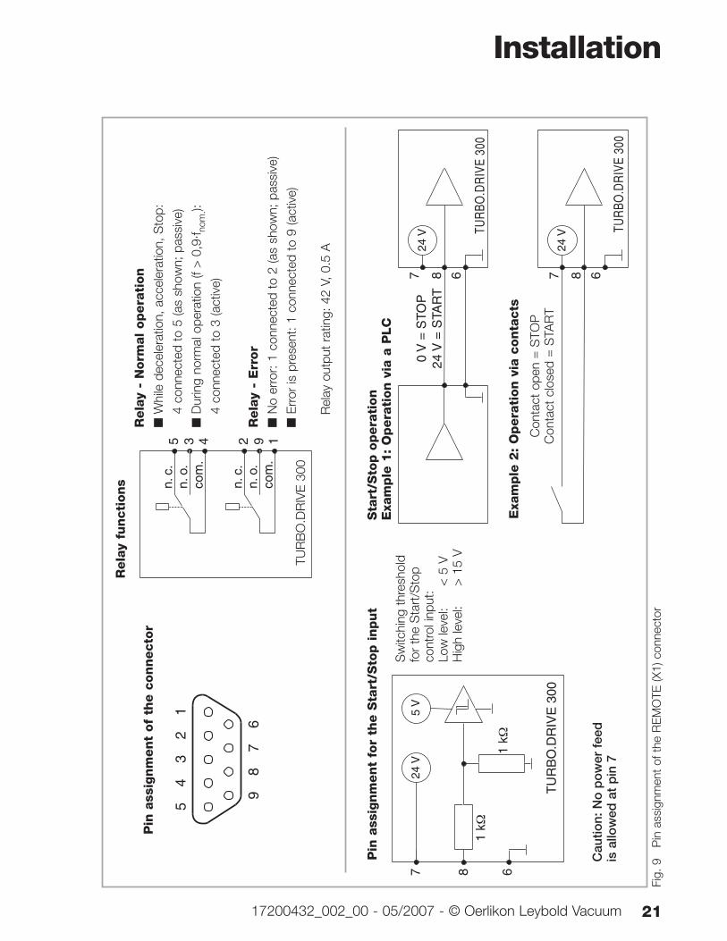
Fig.
9
Pin
ass
ignm
ent
of t
he R
EM
OTE
(X1)
con
nect
or
24 V TU
RBO
.DR
IVE
300
7 8 6
0 V
= S
TOP
24 V
= S
TAR
T
24 V TU
RBO
.DR
IVE
300
7 8 6
Rela
y fu
ncti
ons
87
6
54
32
1
9
Pin
ass
ignm
ent
of
the c
onnecto
r
24 V
5 V
1 kΩ
1 kΩ
TU
RB
O.D
RIV
E 3
00
7 8 6
Pin
ass
ignm
ent
for
the S
tart
/Sto
p i
nput
Sw
itchi
ng t
hres
hold
for
the
Sta
rt/S
top
cont
rol i
nput
:Lo
w le
vel:
< 5
VH
igh
leve
l:>
15
V
Sta
rt/S
top o
pera
tion
Exa
mple
1:
Opera
tion v
ia a
PLC
Con
tact
ope
n =
STO
PC
onta
ct c
lose
d =
STA
RT
Exa
mple
2:
Opera
tion v
ia c
onta
cts
TU
RB
O.D
RIV
E S
5 3 4
n. c
.n.
o.
com
.
2 9 1
n. c
.n.
o.
com
.
Rela
y -
Norm
al
opera
tion
■W
hile
dec
eler
atio
n, a
ccel
erat
ion,
Sto
p:
4 co
nnec
ted
to 5
(as
show
n; p
assi
ve)
■D
urin
g no
rmal
ope
ratio
n (f
> 0
,9·f n
om.):
4 co
nnec
ted
to 3
(act
ive)
Rela
y -
Err
or
■N
o er
ror:
1 c
onne
cted
to
2 (a
s sh
own;
pas
sive
)
■E
rror
is p
rese
nt: 1
con
nect
ed t
o 9
(act
ive)
TUR
BO
.DR
IVE
300
Rel
ay o
utpu
t ra
ting:
42
V, 0
.5 A
Cau
tion:
No
po
wer
fee
dis
allo
wed
at
pin
7
Installation
22 17200432_002_00 - 05/2007 - © Oerlikon Leybold Vacuum
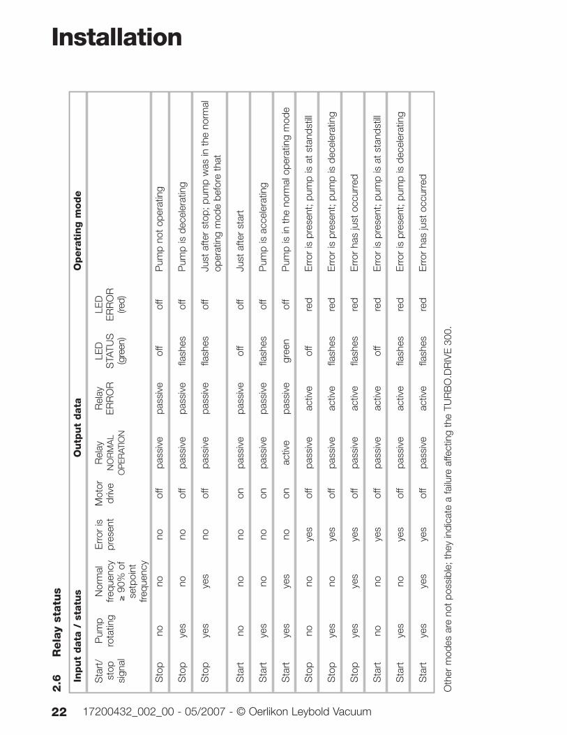
2.6
Rela
y st
atu
s
Oth
er m
odes
are
not
pos
sibl
e; t
hey
indi
cate
a fa
ilure
affe
ctin
g th
e TU
RB
O.D
RIV
E30
0.
Input
data
/ s
tatu
sO
utp
ut
data
Opera
ting m
ode
Sta
rt/
Pum
pN
orm
alE
rror
isM
otor
Rel
ayR
elay
LED
LED
stop
rota
ting
frequ
ency
pres
ent
driv
eN
OR
MA
LE
RR
OR
STA
TUS
ER
RO
Rsi
gnal
≥90
% o
fO
PER
ATIO
N(g
reen
)(re
d)se
tpoi
ntfre
quen
cy
Sto
pno
nono
off
pass
ive
pass
ive
off
off
Pum
p no
t op
erat
ing
Sto
pye
sno
noof
fpa
ssiv
epa
ssiv
efla
shes
off
Pum
p is
dec
eler
atin
g
Sto
pye
sye
sno
off
pass
ive
pass
ive
flash
esof
fJu
st a
fter
stop
; pum
p w
as in
the
nor
mal
op
erat
ing
mod
e be
fore
tha
t
Sta
rtno
nono
onpa
ssiv
epa
ssiv
eof
fof
fJu
st a
fter
star
t
Sta
rtye
sno
noon
pass
ive
pass
ive
flash
esof
fP
ump
is a
ccel
erat
ing
Sta
rtye
sye
sno
onac
tive
pass
ive
gree
nof
fP
ump
is in
the
nor
mal
ope
ratin
g m
ode
Sto
pno
noye
sof
fpa
ssiv
eac
tive
off
red
Err
or is
pre
sent
; pum
p is
at
stan
dstil
l
Sto
pye
sno
yes
off
pass
ive
activ
efla
shes
red
Err
or is
pre
sent
; pum
p is
dec
eler
atin
g
Sto
pye
sye
sye
sof
fpa
ssiv
eac
tive
flash
esre
dE
rror
has
just
occ
urre
d
Sta
rtno
noye
sof
fpa
ssiv
eac
tive
off
red
Err
or is
pre
sent
; pum
p is
at
stan
dstil
l
Sta
rtye
sno
yes
off
pass
ive
activ
efla
shes
red
Err
or is
pre
sent
; pum
p is
dec
eler
atin
g
Sta
rtye
sye
sye
sof
fpa
ssiv
eac
tive
flash
esre
dE
rror
has
just
occ
urre
d
3 Operation
3.1 Interface descriptionThe frequency converter is optionally equipped with serialinterfaces:
■ RS 232/422 C
■ RS 485 C
■ Profibus DP
The TURBO.DRIVE 300 is configured through the parame-ters according to the parameter list. Pxxx denotes parame-ter value xxx.
The PC software "TURBO.DRIVE Server" allows convenientaccess by the user to the parameters of the frequency con-verter.
For further information on the interfaces refer to OperatingInstructions GA 05.281 “Serial Interfaces”.
Operation
2317200432_002_00 - 05/2007 - © Oerlikon Leybold Vacuum
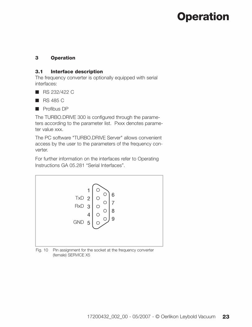
8
7
6
5
4
3
2
1
9
Fig. 10 Pin assignment for the socket at the frequency converter (female) SERVICE X5
TxD
RxD
GND
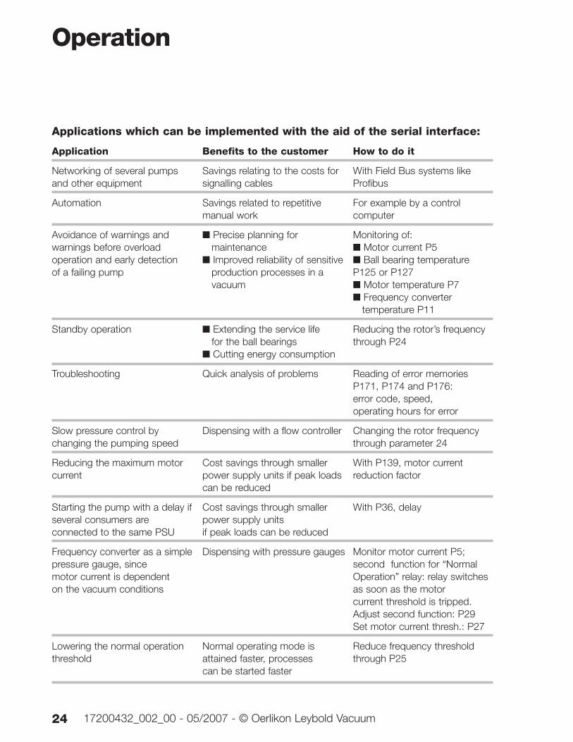
Applications which can be implemented with the aid of the serial interface:
Application Benefits to the customer How to do it
Networking of several pumps Savings relating to the costs for With Field Bus systems like and other equipment signalling cables Profibus
Automation Savings related to repetitive For example by a control manual work computer
Avoidance of warnings and ■ Precise planning for Monitoring of:warnings before overload maintenance ■ Motor current P5operation and early detection ■ Improved reliability of sensitive ■ Ball bearing temperature of a failing pump production processes in a P125 or P127
vacuum ■ Motor temperature P7■ Frequency converter
temperature P11
Standby operation ■ Extending the service life Reducing the rotor’s frequency for the ball bearings through P24
■ Cutting energy consumption
Troubleshooting Quick analysis of problems Reading of error memories P171, P174 and P176: error code, speed, operating hours for error
Slow pressure control by Dispensing with a flow controller Changing the rotor frequency changing the pumping speed through parameter 24
Reducing the maximum motor Cost savings through smaller With P139, motor current current power supply units if peak loads reduction factor
can be reduced
Starting the pump with a delay if Cost savings through smaller With P36, delayseveral consumers are power supply units connected to the same PSU if peak loads can be reduced
Frequency converter as a simple Dispensing with pressure gauges Monitor motor current P5; pressure gauge, since second function for “Normal motor current is dependent Operation” relay: relay switches on the vacuum conditions as soon as the motor
current threshold is tripped.Adjust second function: P29Set motor current thresh.: P27
Lowering the normal operation Normal operating mode is Reduce frequency threshold threshold attained faster, processes through P25
can be started faster
Operation
24 17200432_002_00 - 05/2007 - © Oerlikon Leybold Vacuum
3.1.1 RS 232/422 C interface (SERVICE X5)Standards DIN 66020
Protocol acc. to VDI/VDE 3689
Transmission rate 19200 baud
Response delay default setting 10 ms(parameter 180)
Address range non-addressable
Max. cable length 5 m
Interface connector 9 way Sub-D type, socket on the instrument (female)
thread UNC4-40
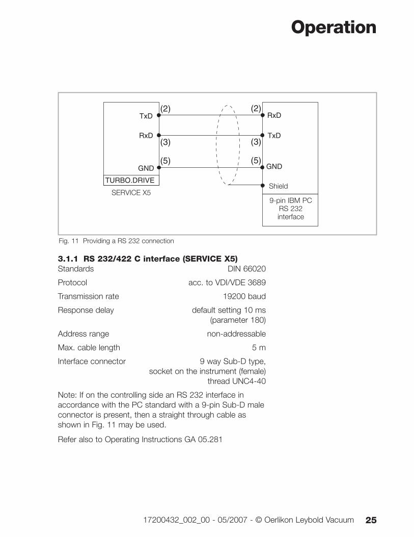
Note: If on the controlling side an RS 232 interface inaccordance with the PC standard with a 9-pin Sub-D maleconnector is present, then a straight through cable asshown in Fig. 11 may be used.
Refer also to Operating Instructions GA 05.281
Operation
2517200432_002_00 - 05/2007 - © Oerlikon Leybold Vacuum
(3)
(5)
(2)
TURBO.DRIVE
TxD
RxD
GND
TxD
RxD
GND
(3)
(5)
(2)
Fig. 11 Providing a RS 232 connection
Shield
9-pin IBM PCRS 232 interface
SERVICE X5
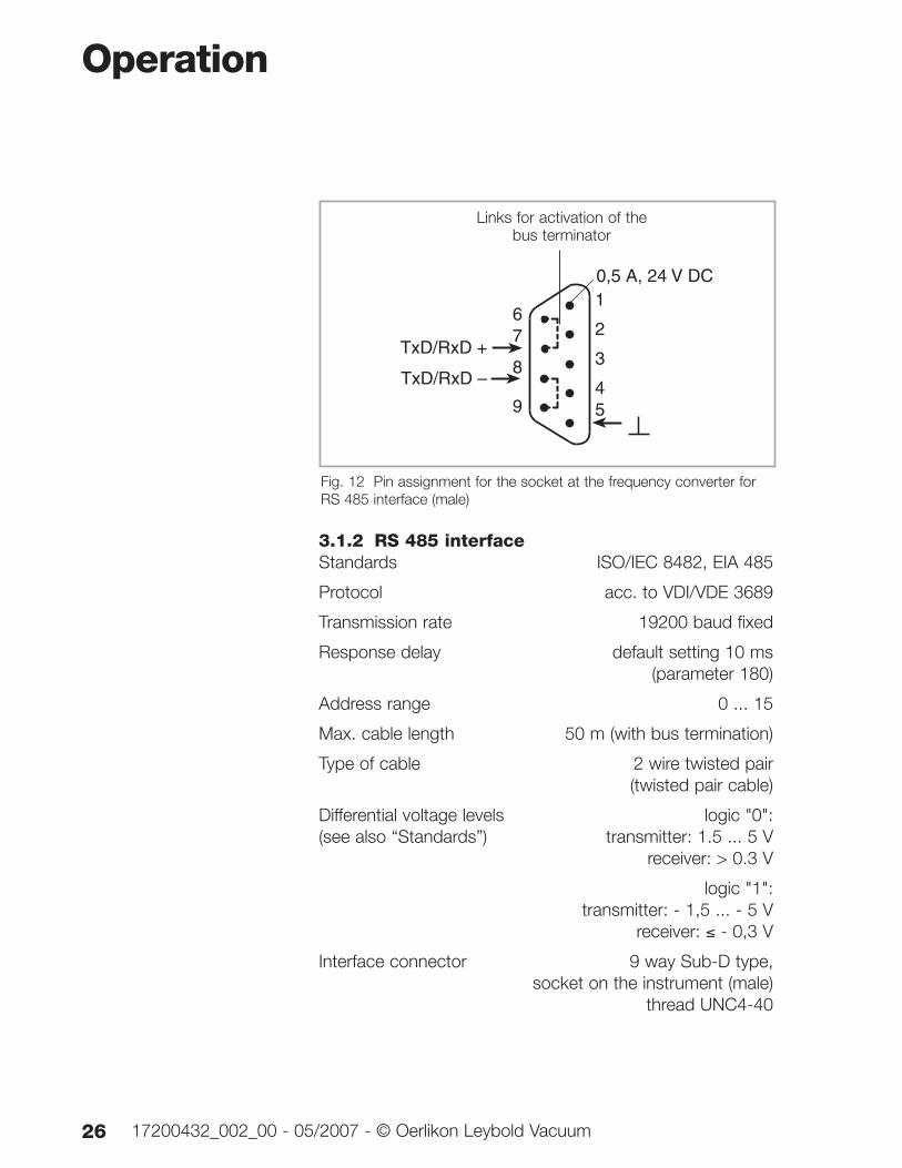
3.1.2 RS 485 interfaceStandards ISO/IEC 8482, EIA 485
Protocol acc. to VDI/VDE 3689
Transmission rate 19200 baud fixed
Response delay default setting 10 ms (parameter 180)
Address range 0 ... 15
Max. cable length 50 m (with bus termination)
Type of cable 2 wire twisted pair (twisted pair cable)
Differential voltage levels logic "0":(see also “Standards”) transmitter: 1.5 ... 5 V
receiver: > 0.3 V
logic "1": transmitter: - 1,5 ... - 5 V
receiver: ≤ - 0,3 V
Interface connector 9 way Sub-D type, socket on the instrument (male)
thread UNC4-40
Operation
26 17200432_002_00 - 05/2007 - © Oerlikon Leybold Vacuum
7
8
9
1
2
3
45
6
TxD/RxD +
TxD/RxD –
0,5 A, 24 V DC
Fig. 12 Pin assignment for the socket at the frequency converter forRS 485 interface (male)
Links for activation of thebus terminator
Operation
2717200432_002_00 - 05/2007 - © Oerlikon Leybold Vacuum
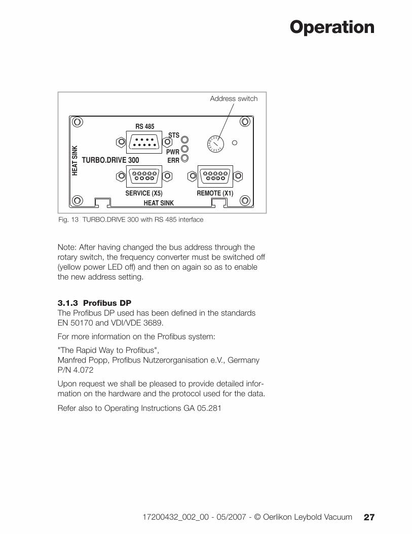
Note: After having changed the bus address through therotary switch, the frequency converter must be switched off(yellow power LED off) and then on again so as to enablethe new address setting.
3.1.3 Profibus DPThe Profibus DP used has been defined in the standardsEN 50170 and VDI/VDE 3689.
For more information on the Profibus system:
"The Rapid Way to Profibus",Manfred Popp, Profibus Nutzerorganisation e.V., GermanyP/N 4.072
Upon request we shall be pleased to provide detailed infor-mation on the hardware and the protocol used for the data.
Refer also to Operating Instructions GA 05.281
HEAT SINK
HEAT
SIN
K
TURBO.DRIVE 300
SERVICE (X5) REMOTE (X1)
STS
PWRERR
RS 485FEDC
BA
9 8 7 6 5 43
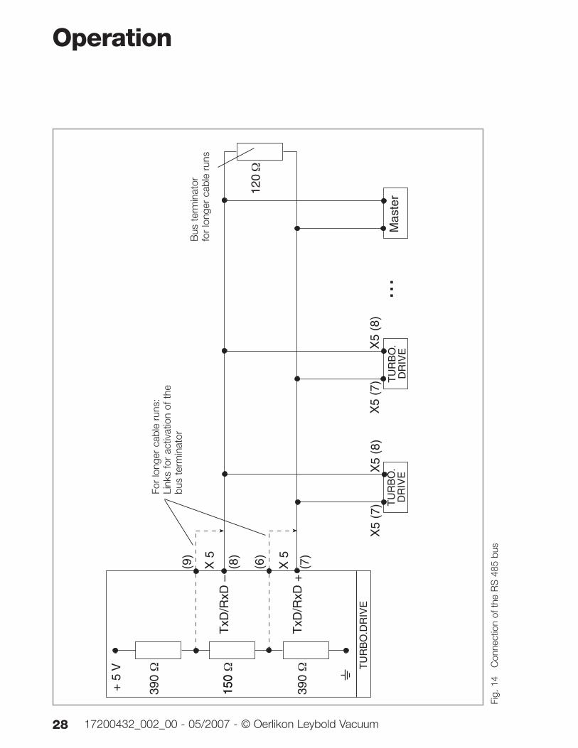
Fig. 13 TURBO.DRIVE 300 with RS 485 interface
Address switch
Operation
28 17200432_002_00 - 05/2007 - © Oerlikon Leybold Vacuum
+ 5
V
390 Ω
150 Ω
390 Ω
X 5
(8)
(7)
TU
RB
O.
DR
IVE
X5
(7)
X5
(8)
X5
(7)
X5
(8)
...
120 Ω
Mas
ter
X 5
(6)
(9)
TxD
/RxD
–
TxD
/RxD
+
150
TU
RB
O.
DR
IVE
TU
RB
O.D
RIV
E
Fig.
14
C
onne
ctio
n of
the
RS
485
bus
For
long
er c
able
run
s:Li
nks
for
activ
atio
n of
the
bus
term
inat
or
Bus
ter
min
ator
fo
r lo
nger
cab
le r
uns
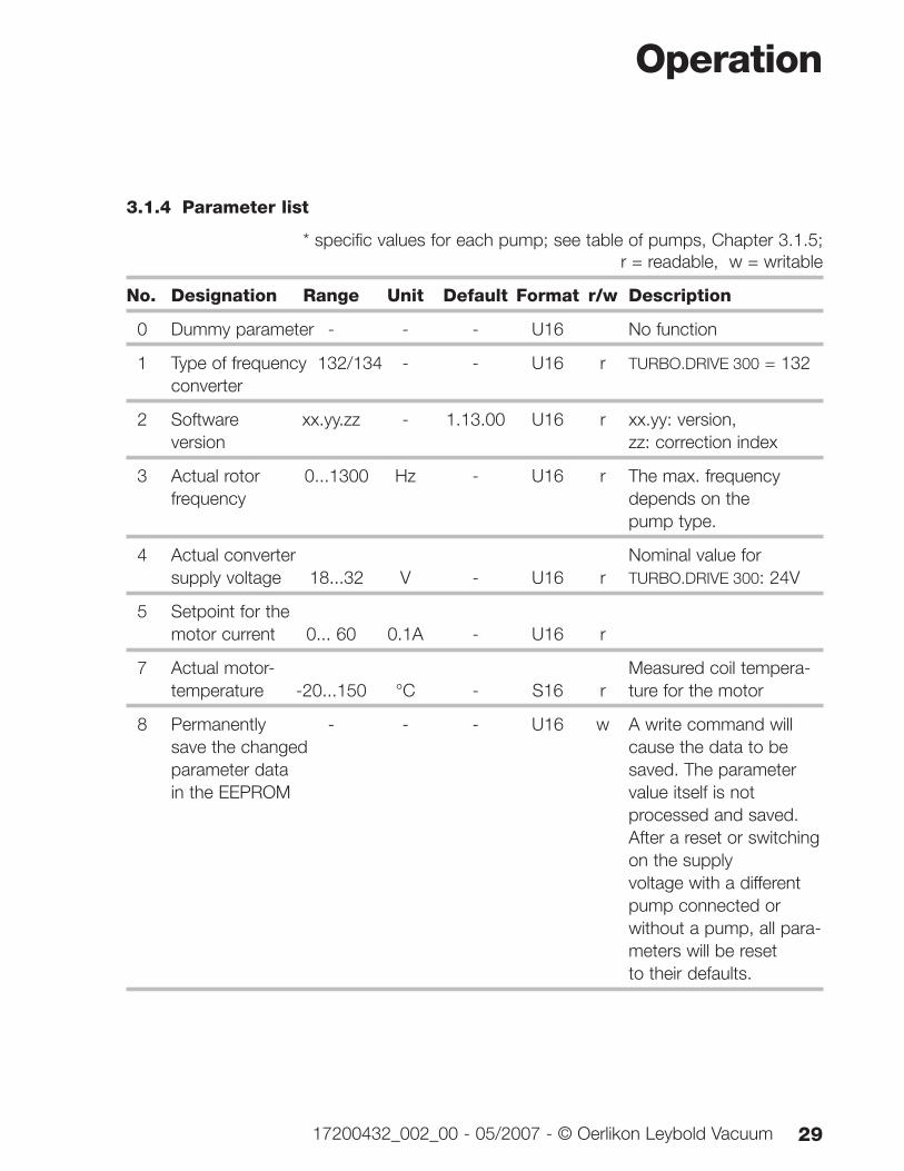
3.1.4 Parameter list
* specific values for each pump; see table of pumps, Chapter 3.1.5; r = readable, w = writable
No. Designation Range Unit Default Format r/w Description
0 Dummy parameter - - - U16 No function
1 Type of frequency 132/134 - - U16 r TURBO.DRIVE 300 = 132converter
2 Software xx.yy.zz - 1.13.00 U16 r xx.yy: version, version zz: correction index
3 Actual rotor 0...1300 Hz - U16 r The max. frequency frequency depends on the
pump type.
4 Actual converter Nominal value for supply voltage 18...32 V - U16 r TURBO.DRIVE 300: 24V
5 Setpoint for the motor current 0... 60 0.1A - U16 r
7 Actual motor- Measured coil tempera-temperature -20...150 °C - S16 r ture for the motor
8 Permanently - - - U16 w A write command will save the changed cause the data to beparameter data saved. The parameter in the EEPROM value itself is not
processed and saved.After a reset or switching on the supply voltage with a different pump connected or without a pump, all para-meters will be resetto their defaults.
Operation
2917200432_002_00 - 05/2007 - © Oerlikon Leybold Vacuum
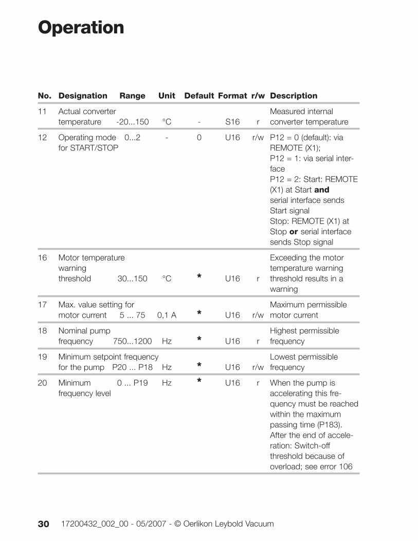
No. Designation Range Unit Default Format r/w Description
11 Actual converter Measured internal temperature -20...150 °C - S16 r converter temperature
12 Operating mode 0...2 - 0 U16 r/w P12 = 0 (default): via for START/STOP REMOTE (X1);
P12 = 1: via serial inter-faceP12 = 2: Start: REMOTE(X1) at Start andserial interface sends Start signalStop: REMOTE (X1) at Stop or serial interface sends Stop signal
16 Motor temperature Exceeding the motor warning temperature warningthreshold 30...150 °C * U16 r threshold results in a
warning
17 Max. value setting for Maximum permissible motor current 5 ... 75 0,1 A * U16 r/w motor current
18 Nominal pump Highest permissible frequency 750...1200 Hz * U16 r frequency
19 Minimum setpoint frequency Lowest permissible for the pump P20 ... P18 Hz * U16 r/w frequency
20 Minimum 0 ... P19 Hz * U16 r When the pump is frequency level accelerating this fre-
quency must be reached within the maximum passing time (P183).After the end of accele-ration: Switch-off threshold because of overload; see error 106
Operation
30 17200432_002_00 - 05/2007 - © Oerlikon Leybold Vacuum
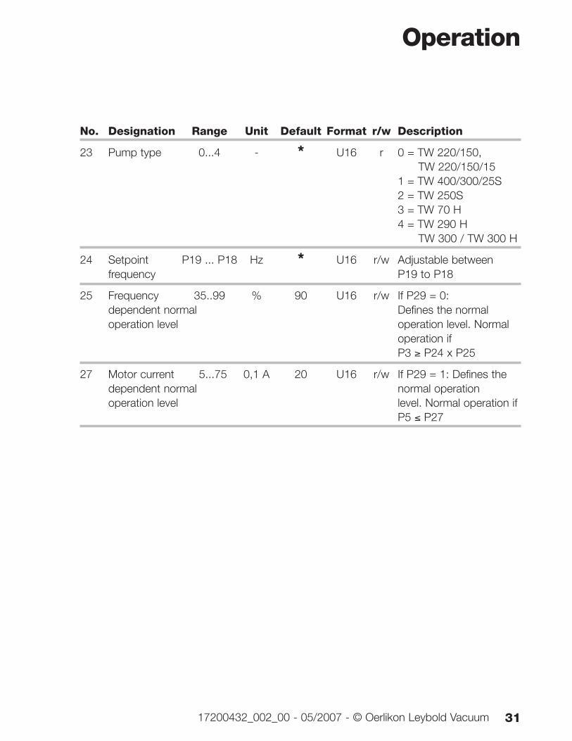
No. Designation Range Unit Default Format r/w Description
23 Pump type 0...4 - * U16 r 0 = TW 220/150, TW 220/150/15
1 = TW 400/300/25S2 = TW 250S3 = TW 70 H4 = TW 290 H
TW 300 / TW 300 H
24 Setpoint P19 ... P18 Hz * U16 r/w Adjustable between frequency P19 to P18
25 Frequency 35..99 % 90 U16 r/w If P29 = 0: dependent normal Defines the normal operation level operation level. Normal
operation if P3 ≥ P24 x P25
27 Motor current 5...75 0,1 A 20 U16 r/w If P29 = 1: Defines the dependent normal normal operationoperation level level. Normal operation if
P5 ≤ P27
Operation
3117200432_002_00 - 05/2007 - © Oerlikon Leybold Vacuum
No. Designation Range Unit Default Format r/w Description
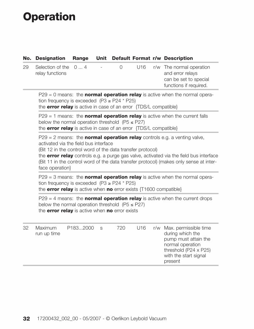
29 Selection of the 0 ... 4 - 0 U16 r/w The normal operation relay functions and error relays
can be set to special functions if required.
P29 = 0 means: the normal operation relay is active when the normal opera-tion frequency is exceeded (P3 ≥ P24 * P25)the error relay is active in case of an error {TDS/L compatible}
P29 = 1 means: the normal operation relay is active when the current fallsbelow the normal operation threshold (P5 ≤ P27)the error relay is active in case of an error {TDS/L compatible}
P29 = 2 means: the normal operation relay controls e.g. a venting valve,activated via the field bus interface (Bit 12 in the control word of the data transfer protocol)the error relay controls e.g. a purge gas valve, activated via the field bus interface (Bit 11 in the control word of the data transfer protocol) (makes only sense at inter-face operation}
P29 = 3 means: the normal operation relay is active when the normal opera-tion frequency is exceeded (P3 ≥ P24 * P25)the error relay is active when no error exists {T1600 compatible}
P29 = 4 means: the normal operation relay is active when the current dropsbelow the normal operation threshold (P5 ≤ P27)the error relay is active when no error exists
32 Maximum P183...2000 s 720 U16 r/w Max. permissible time run up time during which the
pump must attain the normal operation threshold (P24 x P25) with the start signal present
Operation
32 17200432_002_00 - 05/2007 - © Oerlikon Leybold Vacuum
No. Designation Range Unit Default Format r/w Description
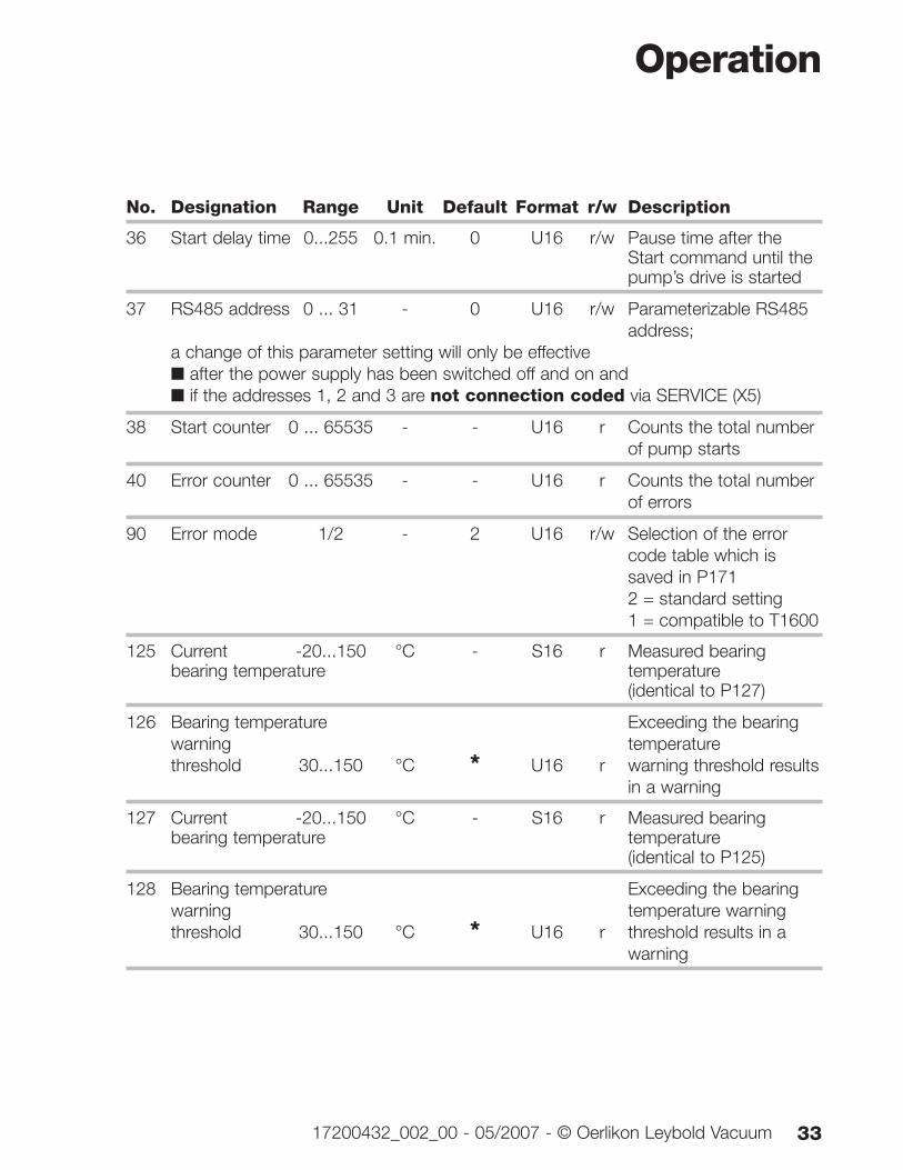
36 Start delay time 0...255 0.1 min. 0 U16 r/w Pause time after the Start command until thepump’s drive is started
37 RS485 address 0 ... 31 - 0 U16 r/w Parameterizable RS485 address;
a change of this parameter setting will only be effective ■ after the power supply has been switched off and on and■ if the addresses 1, 2 and 3 are not connection coded via SERVICE (X5)
38 Start counter 0 ... 65535 - - U16 r Counts the total number of pump starts
40 Error counter 0 ... 65535 - - U16 r Counts the total number of errors
90 Error mode 1/2 - 2 U16 r/w Selection of the error code table which is saved in P1712 = standard setting1 = compatible to T1600
125 Current -20...150 °C - S16 r Measured bearing bearing temperature temperature
(identical to P127)
126 Bearing temperature Exceeding the bearing warning temperaturethreshold 30...150 °C * U16 r warning threshold results
in a warning
127 Current -20...150 °C - S16 r Measured bearing bearing temperature temperature
(identical to P125)
128 Bearing temperature Exceeding the bearing warning temperature warning threshold 30...150 °C * U16 r threshold results in a
warning
Operation
3317200432_002_00 - 05/2007 - © Oerlikon Leybold Vacuum
No. Designation Range Unit Default Format r/w Description
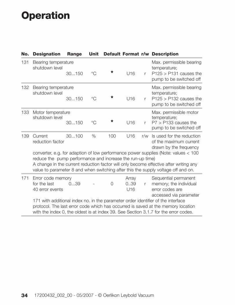
131 Bearing temperature Max. permissible bearingshutdown level temperature;
30...150 °C * U16 r P125 > P131 causes thepump to be switched off
132 Bearing temperature Max. permissible bearingshutdown level temperature;
30...150 °C * U16 r P125 > P132 causes thepump to be switched off
133 Motor temperature Max. permissible motor shutdown level temperature;
30...150 °C * U16 r P7 > P133 causes the pump to be switched off
139 Current 30...100 % 100 U16 r/w Is used for the reduction reduction factor of the maximum current
drawn by the frequency converter, e.g. for adaption of low performance power supplies (Note: values < 100 reduce the pump performance and increase the run-up time)A change in the current reduction factor will only become effective after writing any value to parameter 8 and when switching after this the supply voltage off and on.
171 Error code memory Array Sequential permanent for the last 0...39 - 0 0..39 r memory; the individual 40 error events U16 error codes are
accessed via parameter 171 with additional index no. in the parameter order identifier of the interface protocol. The last error code which has occurred is saved at the memory location with the index 0, the oldest is at index 39. See Section 3.1.7 for the error codes.
Operation
34 17200432_002_00 - 05/2007 - © Oerlikon Leybold Vacuum
No. Designation Range Unit Default Format r/w Description
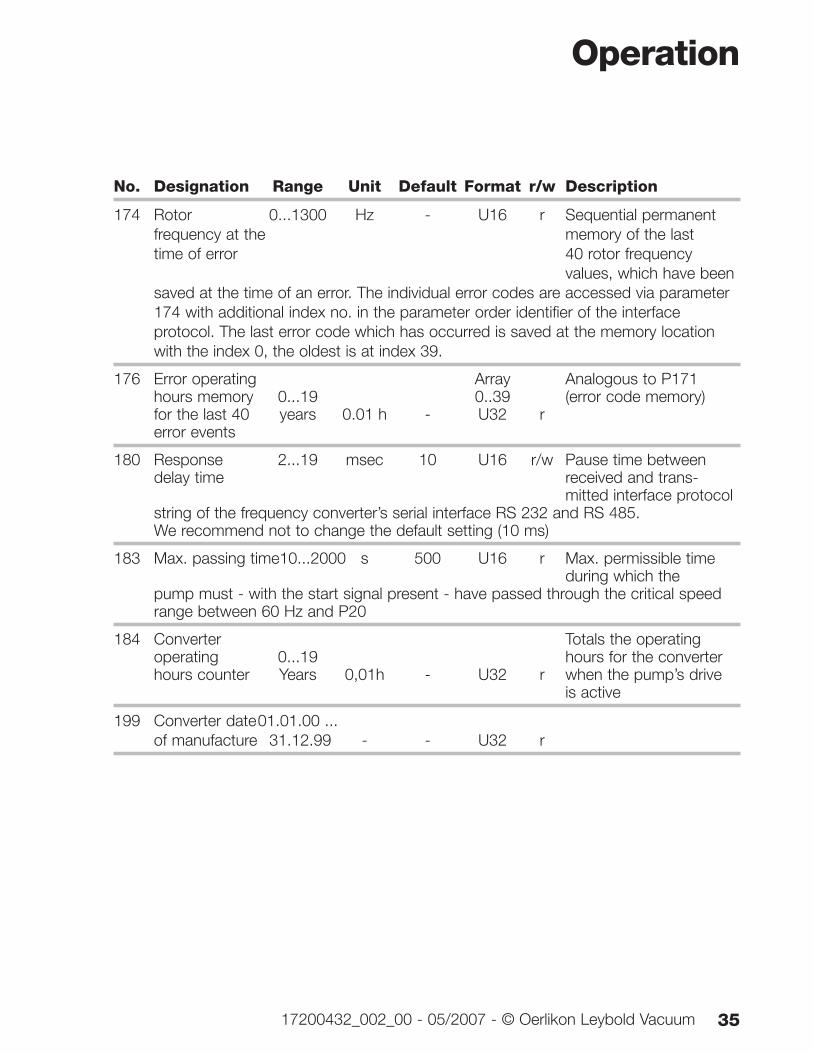
174 Rotor 0...1300 Hz - U16 r Sequential permanent frequency at the memory of the lasttime of error 40 rotor frequency
values, which have beensaved at the time of an error. The individual error codes are accessed via parameter 174 with additional index no. in the parameter order identifier of the interface protocol. The last error code which has occurred is saved at the memory location with the index 0, the oldest is at index 39.
176 Error operating Array Analogous to P171hours memory 0...19 0..39 (error code memory)for the last 40 years 0.01 h - U32 rerror events
180 Response 2...19 msec 10 U16 r/w Pause time between delay time received and trans-
mitted interface protocol string of the frequency converter’s serial interface RS 232 and RS 485. We recommend not to change the default setting (10 ms)
183 Max. passing time10...2000 s 500 U16 r Max. permissible time during which the
pump must - with the start signal present - have passed through the critical speed range between 60 Hz and P20
184 Converter Totals the operating operating 0...19 hours for the converterhours counter Years 0,01h - U32 r when the pump’s drive
is active
199 Converter date01.01.00 ...of manufacture 31.12.99 - - U32 r
Operation
3517200432_002_00 - 05/2007 - © Oerlikon Leybold Vacuum
No. Designation Range Unit Default Format r/w Description
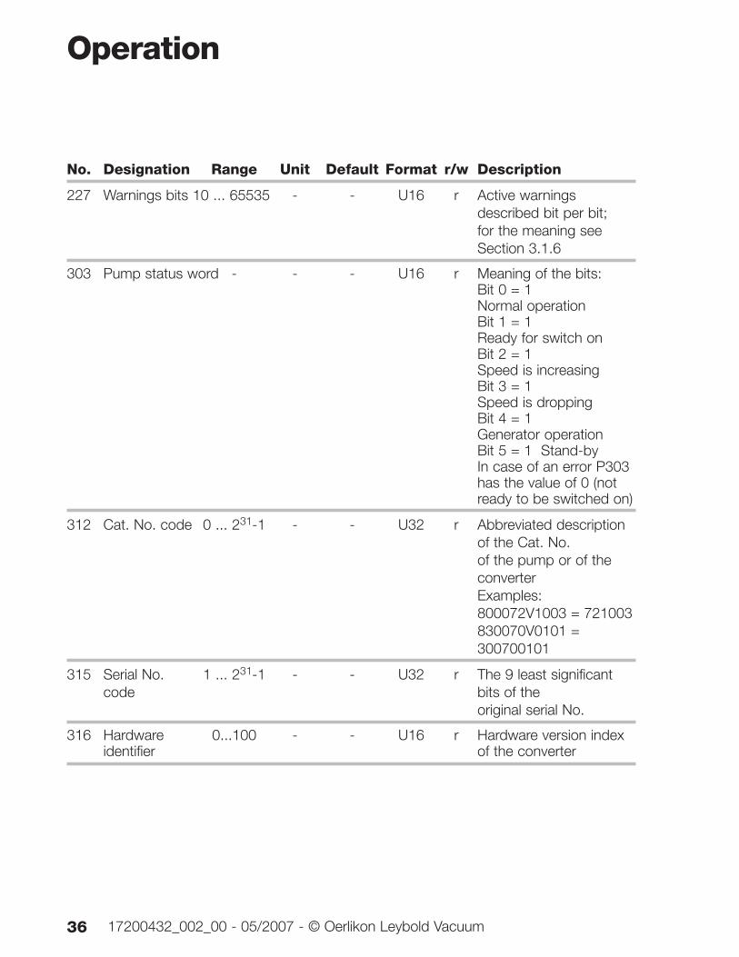
227 Warnings bits 10 ... 65535 - - U16 r Active warnings described bit per bit;for the meaning see Section 3.1.6
303 Pump status word - - - U16 r Meaning of the bits:Bit 0 = 1 Normal operationBit 1 = 1 Ready for switch onBit 2 = 1 Speed is increasingBit 3 = 1 Speed is droppingBit 4 = 1 Generator operationBit 5 = 1 Stand-byIn case of an error P303 has the value of 0 (not ready to be switched on)
312 Cat. No. code 0 ... 231-1 - - U32 r Abbreviated description of the Cat. No. of the pump or of the converterExamples:800072V1003 = 721003830070V0101 = 300700101
315 Serial No. 1 ... 231-1 - - U32 r The 9 least significant code bits of the
original serial No.
316 Hardware 0...100 - - U16 r Hardware version index identifier of the converter
Operation
36 17200432_002_00 - 05/2007 - © Oerlikon Leybold Vacuum
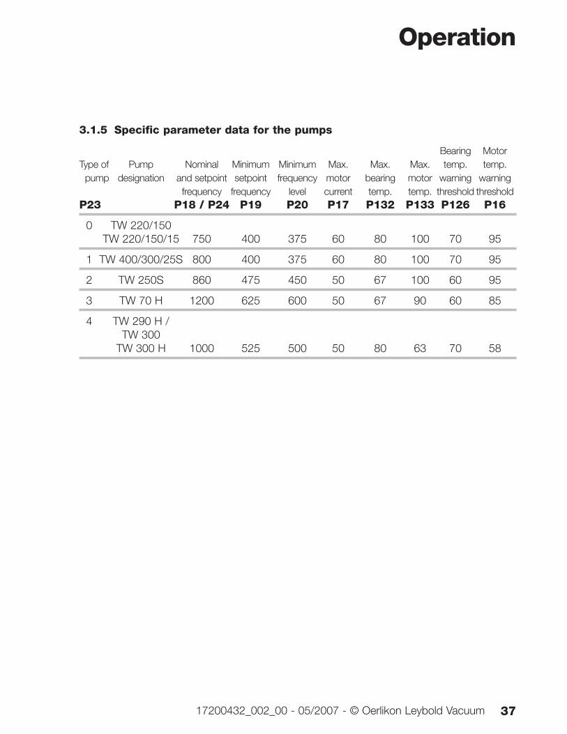
3.1.5 Specific parameter data for the pumps
Bearing MotorType of Pump Nominal Minimum Minimum Max. Max. Max. temp. temp.
pump designation and setpoint setpoint frequency motor bearing motor warning warningfrequency frequency level current temp. temp. threshold threshold
P23 P18 / P24 P19 P20 P17 P132 P133 P126 P16
0 TW 220/150TW 220/150/15 750 400 375 60 80 100 70 95
1 TW 400/300/25S 800 400 375 60 80 100 70 95
2 TW 250S 860 475 450 50 67 100 60 95
3 TW 70 H 1200 625 600 50 67 90 60 85
4 TW 290 H / TW 300
TW 300 H 1000 525 500 50 80 63 70 58
Operation
3717200432_002_00 - 05/2007 - © Oerlikon Leybold Vacuum
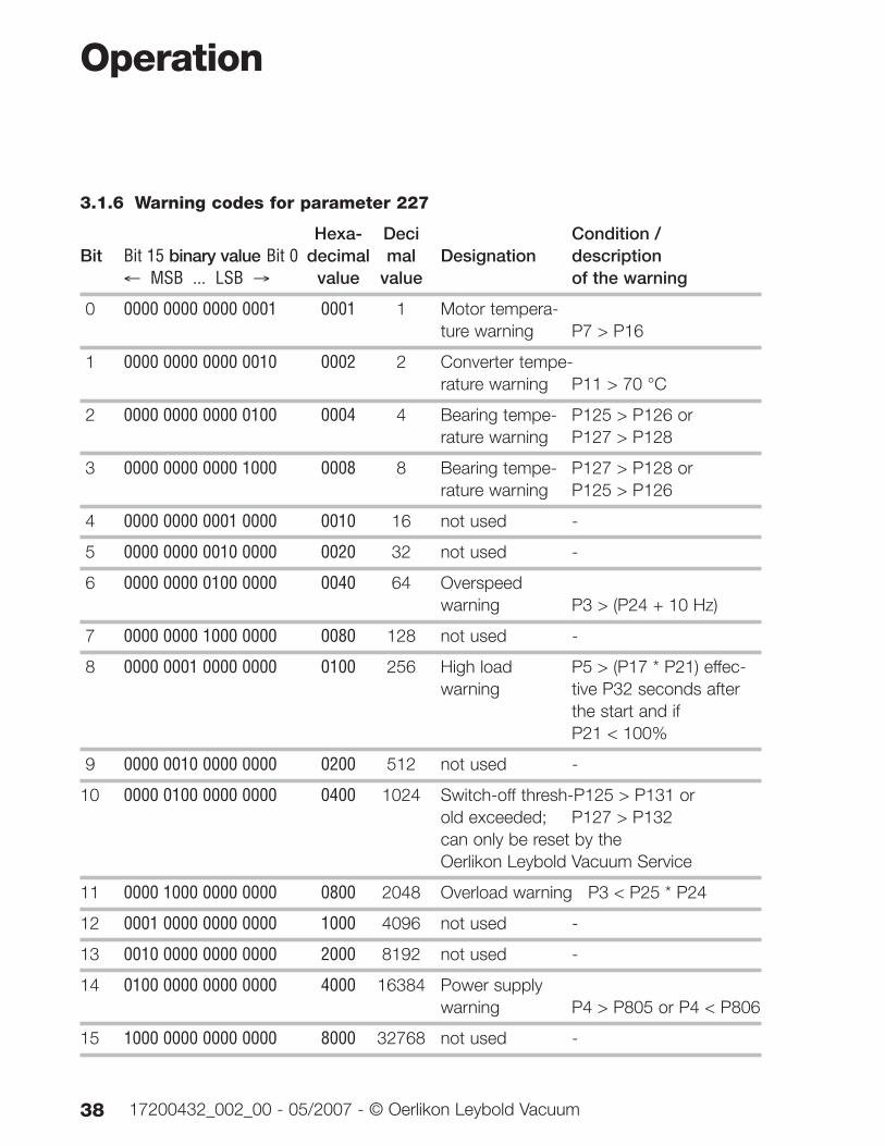
3.1.6 Warning codes for parameter 227
Hexa- Deci Condition / Bit Bit 15 binary value Bit 0 decimal mal Designation description
← MSB ... LSB → value value of the warning
0 0000 0000 0000 0001 0001 1 Motor tempera-ture warning P7 > P16
1 0000 0000 0000 0010 0002 2 Converter tempe-rature warning P11 > 70 °C
2 0000 0000 0000 0100 0004 4 Bearing tempe- P125 > P126 or rature warning P127 > P128
3 0000 0000 0000 1000 0008 8 Bearing tempe- P127 > P128 or rature warning P125 > P126
4 0000 0000 0001 0000 0010 16 not used -
5 0000 0000 0010 0000 0020 32 not used -
6 0000 0000 0100 0000 0040 64 Overspeed warning P3 > (P24 + 10 Hz)
7 0000 0000 1000 0000 0080 128 not used -
8 0000 0001 0000 0000 0100 256 High load P5 > (P17 * P21) effec-warning tive P32 seconds after
the start and if P21 < 100%
9 0000 0010 0000 0000 0200 512 not used -
10 0000 0100 0000 0000 0400 1024 Switch-off thresh-P125 > P131 or old exceeded; P127 > P132can only be reset by the Oerlikon Leybold Vacuum Service
11 0000 1000 0000 0000 0800 2048 Overload warning P3 < P25 * P24
12 0001 0000 0000 0000 1000 4096 not used -
13 0010 0000 0000 0000 2000 8192 not used -
14 0100 0000 0000 0000 4000 16384 Power supply warning P4 > P805 or P4 < P806
15 1000 0000 0000 0000 8000 32768 not used -
Operation
38 17200432_002_00 - 05/2007 - © Oerlikon Leybold Vacuum
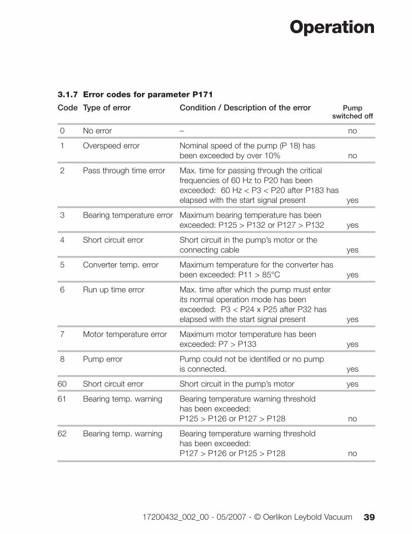
3.1.7 Error codes for parameter P171
Code Type of error Condition / Description of the error Pump switched off
0 No error – no
1 Overspeed error Nominal speed of the pump (P 18) has been exceeded by over 10% no
2 Pass through time error Max. time for passing through the critical frequencies of 60 Hz to P20 has been exceeded: 60 Hz < P3 < P20 after P183 has elapsed with the start signal present yes
3 Bearing temperature error Maximum bearing temperature has been exceeded: P125 > P132 or P127 > P132 yes
4 Short circuit error Short circuit in the pump’s motor or the connecting cable yes
5 Converter temp. error Maximum temperature for the converter has been exceeded: P11 > 85°C yes
6 Run up time error Max. time after which the pump must enter its normal operation mode has been exceeded: P3 < P24 x P25 after P32 has elapsed with the start signal present yes
7 Motor temperature error Maximum motor temperature has been exceeded: P7 > P133 yes
8 Pump error Pump could not be identified or no pump is connected. yes
60 Short circuit error Short circuit in the pump’s motor yes
61 Bearing temp. warning Bearing temperature warning threshold has been exceeded: P125 > P126 or P127 > P128 no
62 Bearing temp. warning Bearing temperature warning threshold has been exceeded: P127 > P126 or P125 > P128 no
Operation
3917200432_002_00 - 05/2007 - © Oerlikon Leybold Vacuum
Code Type of error Condition / Description of the error Pump switched off
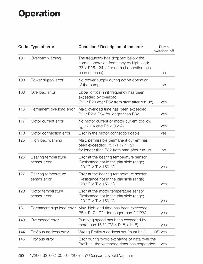
101 Overload warning The frequency has dropped below the normal operation frequency by high load: P3 < P25 * 24 (after normal operation has been reached) no
103 Power supply error No power supply during active operation of the pump no
106 Overload error Upper critical limit frequency has been exceeded by overload(P3 < P20 after P32 from start after run-up) yes
116 Permanent overload error Max. overload time has been exceeded: P3 < P25* P24 for longer than P32 yes
117 Motor current error No motor current or motor current too low (Iset > 1 A and P5 < 0,2 A) yes
118 Motor connection error Error in the motor connection cable yes
125 High load warning Max. permissible permanent current has been exceeded: P5 > P17 * P21for longer than P32 from start after run-up no
126 Bearing temperature Error at the bearing temperature sensor sensor error (Resistance not in the plausible range;
–20 °C < T < 150 °C) yes
127 Bearing temperature Error at the bearing temperature sensor sensor error (Resistance not in the plausible range;
–20 °C < T < 150 °C) yes
128 Motor temperature Error at the motor temperature sensor sensor error (Resistance not in the plausible range;
–20 °C < T < 150 °C) yes
131 Permanent high load error Max. high load time has been exceeded: P5 > P17 * P21 for longer than 2 * P32 yes
143 Overspeed error Pumping speed has been exceeded by more than 15 % (P3 > P18 x 1,15) yes
144 Profibus address error Wrong Profibus address set (must be 0 ... 126) yes
145 Profibus error Error during cyclic exchange of data over the Profibus, the watchdog timer has responded yes
Operation
40 17200432_002_00 - 05/2007 - © Oerlikon Leybold Vacuum
Code Type of error Condition / Description of the error Pump switched off
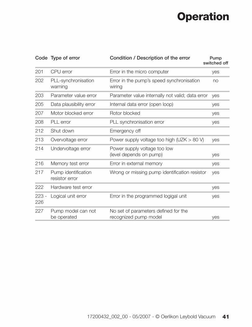
201 CPU error Error in the micro computer yes
202 PLL-synchronisation Error in the pump’s speed synchronisation nowarning wiring
203 Parameter value error Parameter value internally not valid; data error yes
205 Data plausibility error Internal data error (open loop) yes
207 Motor blocked error Rotor blocked yes
208 PLL error PLL synchronisation error yes
212 Shut down Emergency off
213 Overvoltage error Power supply voltage too high (UZK > 80 V) yes
214 Undervoltage error Power supply voltage too low (level depends on pump) yes
216 Memory test error Error in external memory yes
217 Pump identification Wrong or missing pump identification resistor yesresistor error
222 Hardware test error yes
223 - Logical unit error Error in the programmed logigal unit yes226
227 Pump model can not No set of parameters defined for the be operated recognized pump model yes
Operation
4117200432_002_00 - 05/2007 - © Oerlikon Leybold Vacuum
3.2 Switching onSwitch on the DC power supply. The yellow LED at the fre-quency converter lights up.
Switch on the turbomolecular pump at the frequency con-verter
■ via pins 7 and 8 of the socket REMOTE (X1) (For exam-ple via a remote control or with the aid of the plug withintegrated ON/OFF switch: see Section 1.5Accessories).
■ by a start command via the interface; see Section 3.1.
■ For the power supply units offered or recommended byOerlikon Leybold Vacuum: If the contacts 7 and 8 at theREMOTE (X1) connector are closed the pump startsautomatically when the DC voltage is switched on (pro-vided parameter 12 is set to 0).
The turbomolecular pump accelerates. The green LED flas-hes. When the pump reaches normal operation the greenLED lights up permanently.
After a mains power failure the pump can run up auto-matically once more.
Operation
42 17200432_002_00 - 05/2007 - © Oerlikon Leybold Vacuum
Warning
3.3 Shutting downSwitch off the pump at the frequency converter.
■ via contacts 7 and 8 of the socket REMOTE (X1), ifparameter 12 = 0.
■ apply a stop command via the interface, if parameter 12 = 1 or 2.
■ for the power supply units offered or recommended byOerlikon Leybold Vacuum switch off the DC voltage.
After switching off, the green status LED will flash until therotor of the turbomolecular pump is at standstill. This maytake several minutes. With the DC power supply off, theturbomolecular pump will act as a generator supplying thefrequency converter with energy as indicated by the yellowpower LED.
If a failure occurs the turbomolecular pump will be shutdown automatically. The red LED at the frequency conver-ter lights up.
To shut down the frequency converter, switch the pump offand wait until the rotor of the turbomolecular pump hasarrived at standstill (green status LED off).
Then switch the mains power off and wait until the yellowpower LED is off. Then only disconnect any cable connec-tions.
3.4 Emergency shut downThe emergency shutdown facility of a system controllermust be capable of shutting the pump down as detailed inChapter 3.3. The rotor of the turbomolecular pump may bestopped faster by venting the pump; for this refer to theOperating Instructions for the pump.
Operation
4317200432_002_00 - 05/2007 - © Oerlikon Leybold Vacuum
3.5 Setting pumping speed and rotational speedFor the purpose of reducing the pumping speed of thepump because of application requirements or for other rea-sons it can make sense to reduce the rotational speed.
In order to permanently reduce the speed we recommendthe following procedure:
With the aid of a Windows PC and the PC software“TURBO. DRIVE Server” change the setting for the parame-ter 24 “Setpoint frequency”. The possible values for para-meter 24 will depend on the type of pump connected.Parameter 18 “Nominal pump frequency“ defines the maxi-mum value and parameter 19 “Minimum setpoint frequencyfor the pump” defines the minimum value.
So as to retain the value saved for parameter 24 whenswitching the pump off, the parameter value needs to besaved permanently. For this enter any value (for example 1)for parameter 8. Thereafter changed parameters will besaved permanently.
After replacing the pump or when switching on the supplyvoltage without a connected pump, all changed parametervalues will be reset to factory defaults.
The rotational speed of the pump may be changed duringoperation also with the aid of a Windows PC and the PCsoftware “TURBO.DRIVE Server”.
However, we here recommend a PLC compliant solutionwith the aid of the Profibus. The speed can be set over theProfibus in two ways:
■ by changing parameter 24 within the limits defined byparameters 19 and 18 or
■ by transfer as the main setpoint (for this also refer toVDI/VDE 3689).
Operation
44 17200432_002_00 - 05/2007 - © Oerlikon Leybold Vacuum
3.6 Operation at reduced current Not all applications require that the TURBO.DRIVE 300 beoperated at its maximum current. Operation at reducedcurrent will allow operation off a smaller power supply unitor to operate two or more turbomolecular pumps off apower supply unit which in practice is just not strongenough to supply the maximum current for several connec-ted pumps. However, this will increase the run up time, andthe maximum gas throughput and backing pressure specifi-cations are reduced.
For this proceed as follows:
With the aid of a Windows PC and the PC software“TURBO. DRIVE Server” change the setting for the parame-ter 139 “Current reduction factor”. The possible values forparameter 139 can be varied within the limits of 30 to 100% of parameter 17 (current dependents on the type ofconnected pump. The newly entered current reduction fac-tor will only be active after switching off and on again.
So as to retain the value saved for parameter 139 whenswitching the pump off, the parameter value needs to besaved permanently. For this enter any value (for example 1)for parameter 8. Thereafter changed parameters will besaved permanently.
After replacing the pump or when switching on the supplyvoltage without a connected pump, all changed parametervalues will be reset to factory defaults.
Operation
4517200432_002_00 - 05/2007 - © Oerlikon Leybold Vacuum
3.7 Changing the frequency dependent normaloperation levelDepending on the quality of the vacuum which needs to beprovided by the turbomolecular pump it may make senseto reduce the frequency dependent normal operation thres-hold, so that the ready status can be attained faster by thevacuum system. The factory default of 90 % represents agood compromise so that a change will hardly ever berequired.
For this proceed as follows:
With the aid of a Windows PC and the PC software“TURBO. DRIVE Server” change the setting for the parame-ter 25 “Frequency dependent normal operation level”. Thepossible values for parameter 25 can be varied within thelimits of 35 to 99 % of parameter 24 (nominal speeddepends on the type of connected pump).
So as to retain the value saved for parameter 25 whenswitching the pump off, the parameter value needs to besaved permanently. For this enter any value (for example 1)for parameter 8. Thereafter changed parameters will besaved permanently.
After replacing the pump or when switching on the supplyvoltage without a connected pump, all changed parametervalues will be reset to factory defaults.
Operation
46 17200432_002_00 - 05/2007 - © Oerlikon Leybold Vacuum
3.8 Changing the maximum permissible run uptimeIn vacuum systems at a high backing pressure or withincreased quantities of gas during the run up phase, therun up time for the turbomolecular pump may be longer.This will then cause the frequency converter to output anerror message,
The maximum permissible run up time is changed asfollows:
With the aid of a Windows PC and the PC software“TURBO. DRIVE Server” change the setting for the parame-ter 32 “Maximum run up time”. The possible values forparameter 32 can be varied within the limits of P183 to2000 seconds. The default setting is 720 seconds. As arule, no value below 720 seconds should be entered as thiswould give rise to unnecessary error messages. If a signifi-cantly higher value than 720 seconds is required, this mayindicate that the turbomolecular pump is being overloaded.For this reason in such a case the temperature data fromthe frequency converter and the turbomolecular pump(parameter 7 = motor temperature, 11 = frequency conver-ter temperature, 125/127 bearing temperature) should bespecially monitored during application trials.
So as to retain the value saved for parameter 32 whenswitching the pump off, the parameter value needs to besaved permanently. For this enter any value (for example 1)for parameter 8. Thereafter changed parameters will besaved permanently.
After replacing the pump or when switching on the supplyvoltage without a connected pump, all changed parametervalues will be reset to factory defaults.
Operation
4717200432_002_00 - 05/2007 - © Oerlikon Leybold Vacuum
3.9 Changing the start delay timeGenerally it will make sense to let the turbomolecular pumprun up immediately after applying the start command.However when operating two or more turbomolecularpumps off a single power supply unit, it may make sense tostart the pumps one after the other. One way of achievingthis is to enter a start delay time differing from 0.
To set up the start delay time proceed as follows:
With the aid of a Windows PC and the PC software“TURBO. DRIVE Server” change the setting for the parame-ter 36 “Start delay time”. The possible values for parameter36 can be varied within the limits of 0 to 25.5 minutes (0 to255).
So as to retain the value saved for parameter 36 whenswitching the pump off, the parameter value needs to besaved permanently. For this enter any value (for example 1)for parameter 8. Thereafter changed parameters will besaved permanently.
After replacing the pump or when switching on the supplyvoltage without a connected pump, all changed parametervalues will be reset to factory defaults.
Operation
48 17200432_002_00 - 05/2007 - © Oerlikon Leybold Vacuum
3.10 Selecting relay functionsSee parameter 29.
3.11 Reading the error memoryThe TURBO.DRIVE 300 is capable of permanently savingup to 40 error events. The error codes are saved underparameter number 171. In addition to each error code thefollowing is also saved:
■ Rotor frequency at the point of time when the errorevent in parameter 174 occurred.
■ The corresponding number of operating hours in para-meter 176.
Access to each of the 40 groups of values is accomplishedwith the aid of an index value which needs to be statedbesides the parameter number when accessing via the pro-tocol in accordance with VDI / VDE 3689. The range ofindex numbers ranges from 0 to 39.
Operation
4917200432_002_00 - 05/2007 - © Oerlikon Leybold Vacuum
4 MaintenanceThe frequency converter is maintenance free. Repairs mustonly be done by Oerlikon Leybold Vacuum.
If required clean the frequency converter of dust with a drycloth.
When removing a defective frequency converter from aninstallation, please note the information given in Chapter3.3.
During all work on the pump which is being driven by thefrequency converter, the system must be protected againstbeing switched on. For this disconnect the DC powersupply.
Maintenance
50 17200432_002_00 - 05/2007 - © Oerlikon Leybold Vacuum
5 TroubleshootingBefore you start searching for the source of the problem,you should carry out a few simple checks:
Are the connections in good working order?
■ Mains connection,
■ DC power supply to the frequency converter,
■ Connector cable between the frequency converter andthe pump
Is the forevacuum pressure sufficient?
After having removed the cause for the error reset the errormessage at the TURBO.DRIVE:
■ In case of errors with error codes 1 to 7 by applying aSTOP signal via the socket REMOTE (X1) or a resetsequence via the serial interface or by switching themains power off.
■ In case of error code 8 by switching the mains poweroff.
The error codes can only be read if a serial interface is pre-sent (RS 232, RS 485, Profibus).
The following table has been provided as a guide whendetermining the causes of errors.
To remove possible faults, staff having different qualificati-ons is required:
■ Operator of the system
■ Qualified maintenance staff of the system operatoror qualified staff from the vendor erecting the system
■ Staff from Oerlikon Leybold Vacuum Service (OLVService)
In some cases also a combination of the above will be nee-ded, for example, check by the operator, rectification of thefault by maintenance staff.
Troubleshooting
5117200432_002_00 - 05/2007 - © Oerlikon Leybold Vacuum
Troubleshooting
52 17200432_002_00 - 05/2007 - © Oerlikon Leybold Vacuum
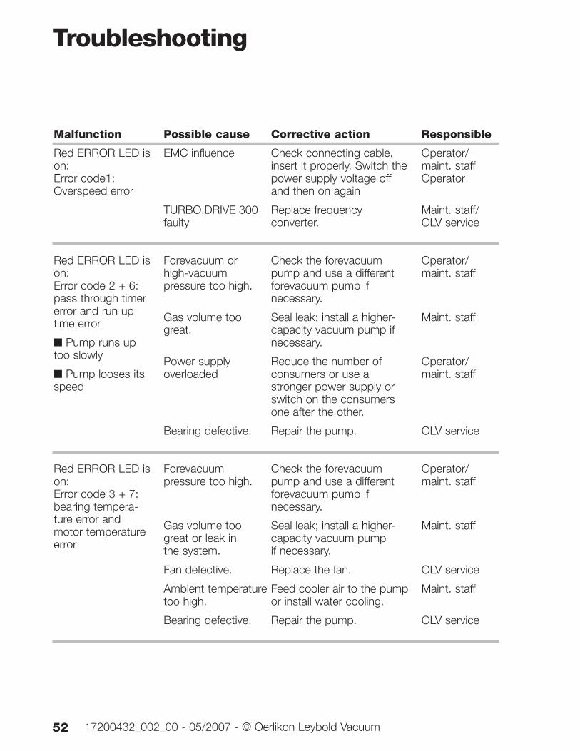
Malfunction
Red ERROR LED ison:Error code1:Overspeed error
Red ERROR LED ison: Error code 2 + 6:pass through timererror and run uptime error
■ Pump runs uptoo slowly
■ Pump looses itsspeed
Red ERROR LED ison:Error code 3 + 7:bearing tempera-ture error andmotor temperatureerror
Possible cause Corrective action
EMC influence Check connecting cable, insert it properly. Switch the power supply voltage off and then on again
TURBO.DRIVE 300 Replace frequency faulty converter.
Forevacuum or Check the forevacuum high-vacuum pump and use a different pressure too high. forevacuum pump if
necessary.
Gas volume too Seal leak; install a higher-great. capacity vacuum pump if
necessary.
Power supply Reduce the number of overloaded consumers or use a
stronger power supply or switch on the consumers one after the other.
Bearing defective. Repair the pump.
Forevacuum Check the forevacuum pressure too high. pump and use a different
forevacuum pump if necessary.
Gas volume too Seal leak; install a higher-great or leak in capacity vacuum pump the system. if necessary.
Fan defective. Replace the fan.
Ambient temperature Feed cooler air to the pump too high. or install water cooling.
Bearing defective. Repair the pump.
Responsible
Operator/maint. staffOperator
Maint. staff/OLV service
Operator/maint. staff
Maint. staff
Operator/maint. staff
OLV service
Operator/maint. staff
Maint. staff
OLV service
Maint. staff
OLV service
Troubleshooting
5317200432_002_00 - 05/2007 - © Oerlikon Leybold Vacuum
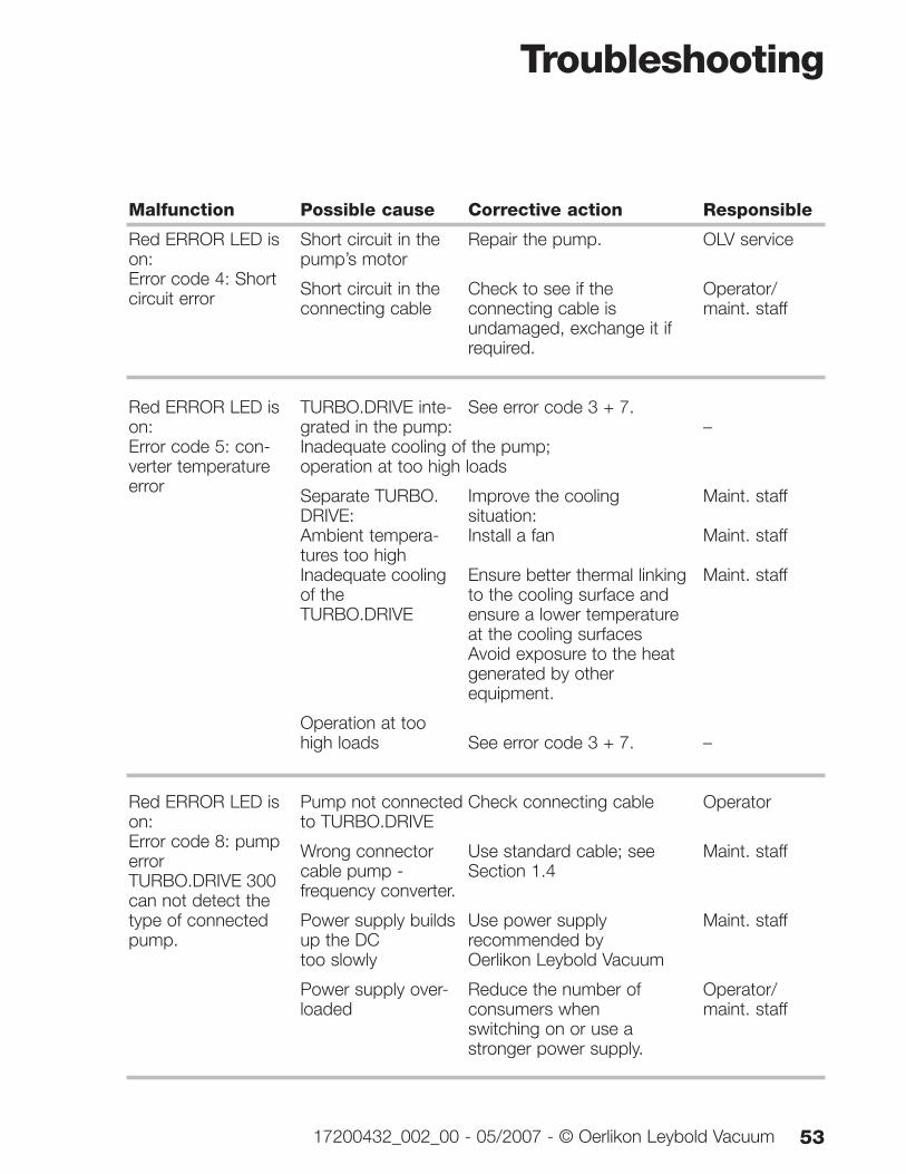
Malfunction
Red ERROR LED ison:Error code 4: Shortcircuit error
Red ERROR LED ison: Error code 5: con-verter temperatureerror
Red ERROR LED ison: Error code 8: pumperrorTURBO.DRIVE 300can not detect thetype of connectedpump.
Possible cause Corrective action
Short circuit in the Repair the pump.pump’s motor
Short circuit in the Check to see if the connecting cable connecting cable is
undamaged, exchange it if required.
TURBO.DRIVE inte- See error code 3 + 7.grated in the pump: Inadequate cooling of the pump; operation at too high loads
Separate TURBO. Improve the cooling DRIVE: situation:Ambient tempera- Install a fantures too highInadequate cooling Ensure better thermal linkingof the to the cooling surface and TURBO.DRIVE ensure a lower temperature
at the cooling surfacesAvoid exposure to the heat generated by other equipment.
Operation at too high loads See error code 3 + 7.
Pump not connected Check connecting cableto TURBO.DRIVE
Wrong connector Use standard cable; see cable pump - Section 1.4frequency converter.
Power supply builds Use power supply up the DC recommended by too slowly Oerlikon Leybold Vacuum
Power supply over- Reduce the number of loaded consumers when
switching on or use a stronger power supply.
Responsible
OLV service
Operator/maint. staff
–
Maint. staff
Maint. staff
Maint. staff
–
Operator
Maint. staff
Maint. staff
Operator/maint. staff
Troubleshooting
54 17200432_002_00 - 05/2007 - © Oerlikon Leybold Vacuum
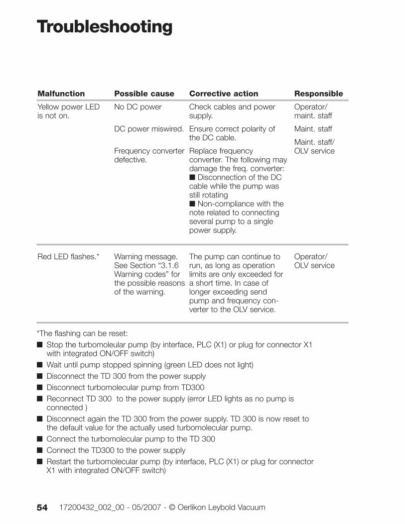
Malfunction
Yellow power LEDis not on.
Red LED flashes.*
Possible cause Corrective action
No DC power Check cables and power supply.
DC power miswired. Ensure correct polarity of the DC cable.
Frequency converter Replace frequency defective. converter. The following may
damage the freq. converter:■ Disconnection of the DC cable while the pump was still rotating■ Non-compliance with the note related to connecting several pump to a single power supply.
Warning message. The pump can continue to See Section “3.1.6 run, as long as operation Warning codes” for limits are only exceeded for the possible reasons a short time. In case of of the warning. longer exceeding send
pump and frequency con-verter to the OLV service.
Responsible
Operator/maint. staff
Maint. staff
Maint. staff/OLV service
Operator/OLV service
*The flashing can be reset: ■ Stop the turbomoleular pump (by interface, PLC (X1) or plug for connector X1
with integrated ON/OFF switch)■ Wait until pump stopped spinning (green LED does not light)■ Disconnect the TD 300 from the power supply■ Disconnect turbomolecular pump from TD300■ Reconnect TD 300 to the power supply (error LED lights as no pump is
connected )■ Disconnect again the TD 300 from the power supply. TD 300 is now reset to
the default value for the actually used turbomolecular pump.■ Connect the turbomolecular pump to the TD 300■ Connect the TD300 to the power supply■ Restart the turbomolecular pump (by interface, PLC (X1) or plug for connector
X1 with integrated ON/OFF switch)
Troubleshooting
5517200432_002_00 - 05/2007 - © Oerlikon Leybold Vacuum
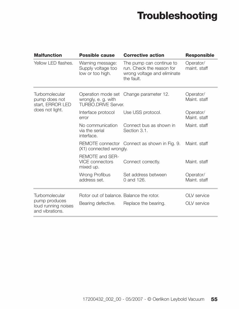
Malfunction
Yellow LED flashes.
Turbomolecularpump does notstart, ERROR LEDdoes not light.
Turbomolecularpump producesloud running noisesand vibrations.
Possible cause Corrective action
Warning message: The pump can continue to Supply voltage too run. Check the reason for low or too high. wrong voltage and eliminate
the fault.
Operation mode set Change parameter 12.wrongly, e. g. with TURBO.DRIVE Server.
Interface protocol Use USS protocol.error
No communication Connect bus as shown in via the serial Section 3.1.interface.
REMOTE connector Connect as shown in Fig. 9.(X1) connected wrongly.
REMOTE and SER-VICE connectors Connect correctly.mixed up.
Wrong Profibus Set address between address set. 0 and 126.
Rotor out of balance. Balance the rotor.
Bearing defective. Replace the bearing.
Responsible
Operator/maint. staff
Operator/Maint. staff
Operator/Maint. staff
Maint. staff
Maint. staff
Maint. staff
Operator/Maint. staff
OLV service
OLV service
Troubleshooting
56 17200432_002_00 - 05/2007 - © Oerlikon Leybold Vacuum
Malfunction
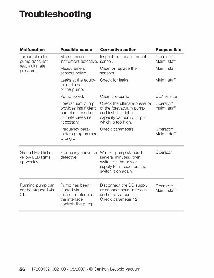
Turbomolecularpump does notreach ultimatepressure.
Green LED blinks,yellow LED lightsup weakly.
Running pump cannot be stopped viaX1.
Possible cause Corrective action
Measurement Inspect the measurement instrument defective. sensor.
Measurement Clean or replace the sensors soiled. sensors.
Leaks at the equip- Check for leaks.ment, lines or the pump.
Pump soiled. Clean the pump.
Forevacuum pump Check the ultimate pressure provides insufficient of the forevacuum pump pumping speed or and install a higher-ultimate pressure capacity vacuum pump ifnecessary. which is too high.
Frequency para- Check parameters.meters programmed wrongly.
Frequency converter Wait for pump standstill defective. (several minutes), then
switch off the power supply for 5 seconds and switch it on again.
Pump has been Disconnect the DC supply started via or connect serial interface the serial interface, and stop via bus.the interface Check parameter 12.controls the pump.
Responsible
Operator/Maint. staff
Maint. staff
Maint. staff
OLV service
Operator/maint. staff
Operator/Maint. staff
Operator
Operator/Maint. staff
5717200432_002_00 - 05/2007 - © Oerlikon Leybold Vacuum
The frequency converter TURBO.DRIVE 300 has beentested by the TÜV Rheinland of North America according tothe requirements of
■ NRTL(applied standards UL 61010A-1: 2002)
It complies with the standards stated.
Certificate No. US 72030360 01
NRTL
58 17200432_002_00 - 05/2007 - © Oerlikon Leybold Vacuum
Notes
5917200432_002_00 - 05/2007 - © Oerlikon Leybold Vacuum
OerlikonLeybold Vacuum GmbHBonner Strasse 498 D-50968 ColognePhone: +49-(0)221-347 0Fax: +49-(0)221-347 [email protected]
_092
54_2
007
05.0
7
w w w. o e r l i k o n . c o m


![10 - nippon-sokki.co.jpIT8000 1500V I T8000 Your Power Testing Solution RE—: 22501/ — 51] . Il . 270 000 000 000 -300 -75 -300- 150 -300 -225 -300- 450 -300 -675 -300- 900 -300-](https://img.pdfslide.us/doc/110x75/60c2bc0ba30d370d17745efa/10-nippon-sokkicojp-it8000-1500v-i-t8000-your-power-testing-solution-rea.jpg)


![MarcopoloMarcopolo 300角 300×600角 400角 マルコポーロ 磨 ¥14,300/ 300角 300×300×13mm [¥1,300/枚] 11枚/ 8枚/ケース・25 300×600角 300×600×13mm [¥2,600/枚]](https://img.pdfslide.us/doc/110x75/5fee0cc94b2f1a341a4487d3/marcopolo-marcopolo-300e-300600e-400e-fffff-c-i14300.jpg)