Embed Size (px)
Citation preview
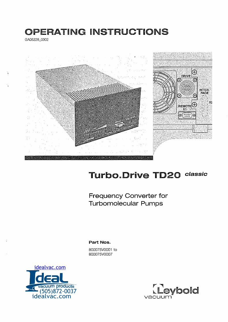
OPERATING INSTRUCTmONS
INTERFACE
Turbo.Drive TD20 classic
Frequency Converter for Turbomolecular Pumps
Part Nos.
B00075V0001 to B00075V0007
r--., b-.Leybold
vacuurTI (505)872-0037
idealvac.com
idealvac.com
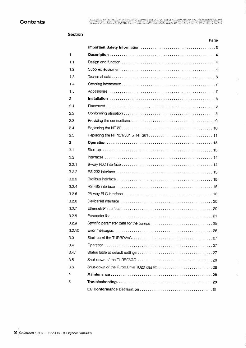
Contents
Section
1
1.1
1.2
1.3
1.4
1.5
2
2.1
2.2
2.3
2.4
2.5
3
3.1
3.2
3.2.1
3.2.2
3.2.3
3.2.4
3.2.5
3.2.6
3.2.7
3.2.8
3.2.9
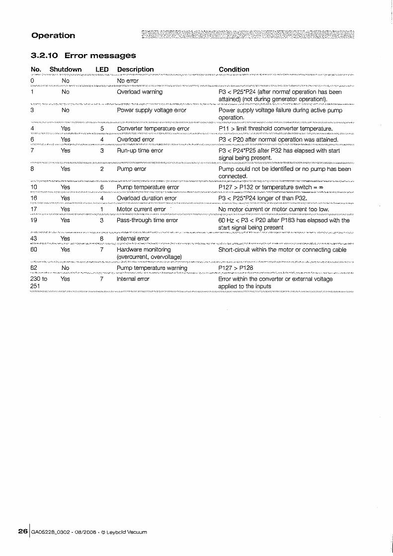
3.2.10
3.3
3.4
3.4.1
3.5
3.6
4
5
Page
Important Safety Information . ................................... 3
Description . .................................................. 4
Design and function ............................................. 4
Supplied equipment ............................................. 4
Technical data .................................................. 6
Ordering information ............................................. 7
Accessories ........... , ....... ,., .... , .. , , ....... , , .... , . , , , , , 7
Installation ................................................... 8
Placement. .................................................... 8
Conforming utilisation ............................................ 8
Providing the connections .......... ' ............................... 9
Replacing the NT 20 ............................................ 1 0
Replacing the NT 151/361 or NT 361 ............................... 11
Operation ..........•........................................ 13
Start-up ..................................................... 13
Interfaces .................................................... 14
9-way PLC interface ............................................ 14
RS 232 interface ............................................... 15
Profibus interface .............................................. 16
RS 485 interface ............................................... 16
25-way PLC interface ........................................... 18
DeviceNet interface ............................................. 20
EthernetllP interface ............................................ 20
Parameter list ................................................. 21
Specific parameter data for the pumps .............................. 25
Error messages ................................................ 26
Start-up of the TURBOVAC ....................................... 27
Operation .................................................... 27
Status table at default settings .................................... 27
Shut-down of the TURBOVAC .................................... 28
Shut-down olthe TurboDrive TD20 classic .......................... 28
Maintenance . ........................•................•...... 28
Troubleshooting . ............................................. 29
EC Conformance Declaration . .................................. 31
21 GA05228_0302 - 08/2006 - © Leybold Vacuum
Safety Information
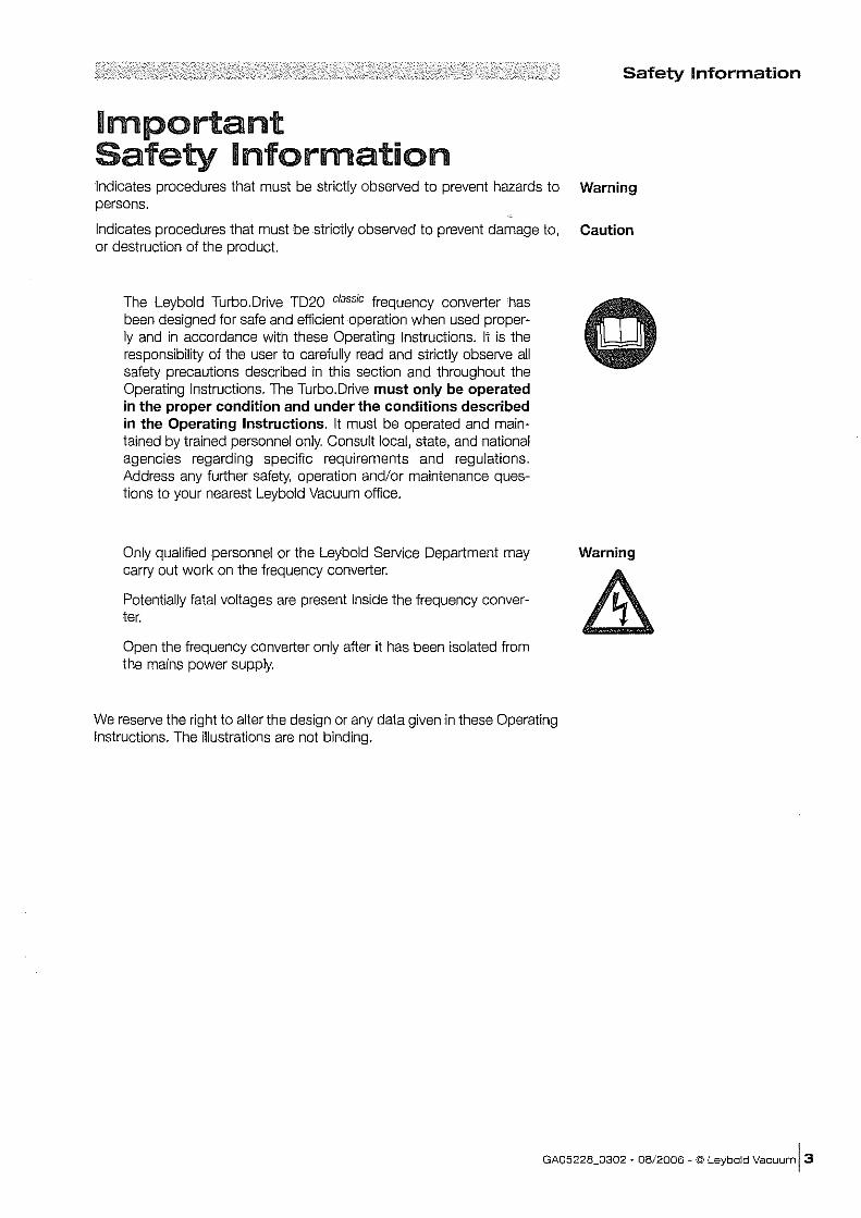
mmportant Safety Information Indicates procedures that must be strictly observed to prevent hazards to Warning persons.
Indicates procedures that must be strictly observed to prevent damage to, Caution or destruction of the product.
The Leybold Turbo.Drive TD20 classic frequency converter has been designed for safe and efficient operation when used properly and in accordance with these Operating Instructions. It is the responsibility of the user to carefully read and strictly observe all safety precautions described in this section and throughout the Operating Instructions. The TurboDrive must only be operated in the proper condition and under the conditions described in the Operating Instructions. It must be operated and maintained by trained personnel only. Consult local, state, and national agencies regarding specific requirements and regulations. Address any further safety, operation and/or maintenance questions to your nearest Leybold Vacuum office.
Only qualified personnel or the Leybold Service Department may carry out work on the frequency converter.
Potentially fatal voltages are present inside the frequency converter.
Open the frequency converter only after it has been isolated from the mains power supply.
We reserve the right to alter the design or any data given in these Operating Instructions. The illustrations are not binding.
Warning
GA05228_0302 . 08/2006 - © Leybold Vacuum 13
Description
1 Description 1.1 Design and function The electronic frequency converter Turbo. Drive TD20 classic is used to drive the following turbo molecular pumps: TURBOVAC 151, 151 C, 361, 361 C, TURBOVAC 600, 600 C, TURBOVAC 1000, 1000 C, 1100 C.
These pumps each comprise a three-phase asynchronous motor with the appropriate rating to drive the rotor.
The TurboDrive TD20 classic converts the single-phase mains voltage into a three-phase AC voltage with regulated frequency and amplitude.
Coding Each installed TURBOVAC has been individually coded. The acceleration sequence, the regulation during operation, and the output speed will vary depending on the installed pump model.
The Turbo.Drive TD20 classic has a 9-way PLC interface as standard and additional interfaces as option. It can be connected directly to mains voltage.
The Turbo.Drive TD20 classic can be connected directly to mains voltage.
1.2 Supplied equipment TurboDrive TD20 classic table-top electronic frequency converter with housing, Operating Instructions.
41 GA05228_0302 - 08/2006 - © Leybold Vacuum
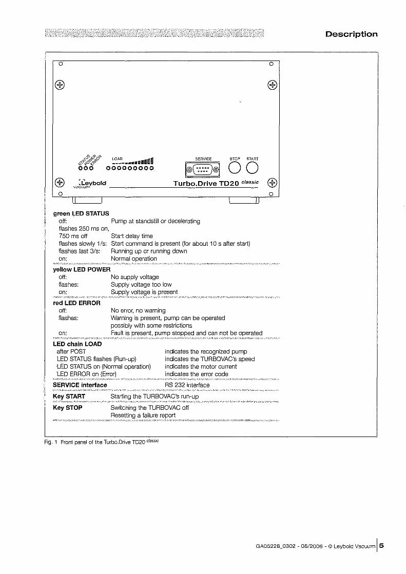
o
LOAD ". __ .. ___ .d.lIlO ..
000000000
SERVICE STOP START
~§§ 00 :LeybOld Turbo.Drive TD20 classic
vLlcul.In'\ ________ ---''-=-:..:::====---=--===--__ o
green LED STATUS off: Pump at standstill or decelerating flashes 250 ms on, 750 ms off Start delay time flashes slowly 1 Is: Start command is present (for about 10 s after start) flashes fast 3/s: Running up or running down on: Normal oOl3ration
yellow LED POWER off: No supply voltage flashes: Supply voltage too low on:
red LED ERROR off: flashes:
on:
LED chain LOAD after POST
is
No error, no warning Warning is present, purnp can be operated possibly with some restrictions Fault is present, pump stopped and can not be operated
, """",",,",,,,/,.,, "/"~~"",,,,--,,,,
LED STATUS flashes (Run-up) indicates the recognized pump indicates the TURBOVAC's speed indicates the motor current indicates the error code
LED STATUS on (Normal operation) LED ERROR on
SERVICE interface
START
Key STOP
RS 232 interface
Staltino the TURBOVAC's
Switching the TURBOVAC off a failure
Fig. 1 Front panel of the Turbo.Drive TD20 cli;1ssic
Description
o
o
GA05228_0302 - 08/2006 - © Leybold Vacuum 15
Description
1
----213-----1
1----198---_
1'<3'1 ij ij TUfbo.D,I~B TD~O ....... €m
Fig. 2 Dimensional drawing for the Turbo.Drive TD20 claSSiC, dimensions in mm
1.3 Technical data Mains connection 100 to 240 V AC -15%1+10%,
50/60 Hz
Power consumption tolerance including options
Power consumption of the TURBOVAC
< 500 VA
< 400 VA
Power output (motor) Nominal voltage Motor current limitation
Acceleration (max. 10 min.) Continuous operation
Frequency
TURBOVAC speed ratings
TURBOVAC 151
TURBOVAC 361
TURBOVAC 600
TURBOVAC 1000 TURBOVAC 1100
Ambient temperature
Storage temperature
Relative air humidity
Type of protection to EN 6059
Electrical safety to EN 61010-1
Interference radiation to 61326-1
EMC to IEC 801-2
Dimensions
Weight
61 GA05228_0302 - 08/2006 - © Leybold Vacuum
47V
5A 3.5A
o to 835 Hz
49,980 min-1
45,000 min-1
36,000 min-1
36,000 min-1
30,000 min-1
0-45 'C
-25 'C ... + 70 'C
5 to 85 % (non-condensing)
IP 20
Class A
Severity 2
1/219",3HU
4 kg
11.4 Ordering information
Frequency converter Turbo.Drive TD20 classic
with 9-way PLC interface with additional RS 232 interface with additional Profibus interface with additional RS 485 interface with additional 25-way PLC interface with additional DeviceNet interface with additional EthernetilP interface
1.5 Accessories Connection line to the TURBOVAC
3 m long 5 m long 10 rn long 20m
Power line cord 2 m long, Euro plug 2 rn long, US plug 6-15 P 3 m long, Euro plug 3rn US 6-15P
Plug for 9-way PLC connector with integrated ON/OFF switch for the purnp
frame 1 g", 3HU
Adapter cable, 0.2 m long, 25-way PLC interface-2x Phoenix connector of the NT 20
Adapter cable, DRIVE connector of the Turbo.Drive TD20 classic - TURBOVAC connection cable of the NT 151/361 or NT 361
Accessories for serial interfaces
PC software "Turbo. Drive Server" for Windows 95 and higher, CD-ROM III Display, change, save and compare parameter lists iii Integration of customer's software III Record parameter data (Software supports only RS 232, RS 485 and Profibus) The software can also be downloaded from
~1,~X.b?12:S2Ti::t~~T~~~§~RE°rt§ IJ?;':'.~L~,~.~~.,
Part No.
800075V0001 800075V0002 800075V0003 800075V0004 800075V0005 B00075V0006 800075V0007
85765 85766 85767 85768
800102V0001 800102V1001 800102V0002 800102V1002
15248
161 00
800152V0020
800000006
800110V0102
""',',',"",', ..
Description
@J",,,,,,,,,,,,,, ... ~
ill] g
GA05228_0302 - 08/2006 - © Leybold Vacuum [7
Installation
2 mnstallation Warning Only qualified personnel or the Leybold Service Department may
Warning
& Warning
Warning
carry out work on the frequency converter.
Potentially fatal voltages are present inside the frequency converter.
Open the frequency converter only after it has been isolated from the mains power supply.
2.1 Placement Place the Turbo.Drive TD20 classic on a fiat, smooth surface.
For installation in a rack use the mounting frame 1 goo, 3 HU.
The heat dissipation of the TurboDrive TD20 classic must not be obstructed. Insure a sufficient ventilation - the ambient temperature during operation must not exceed 45°C (113 oF).
If the TurboDrive TD20 classic is built into a rack the mains plug is not within easy reach. Therefore install a separation between the Turbo.Drive TD20 classic and the mains when you build it into a rack.
Do not operate the TurboDrive TD20 classic with the standard mains lead in chemically aggressive surroundings. If you operate the TurboDrive TD20 classic in chemically aggressive surroundings replace the mains lead by a resistant one.
2.2 Conforming utilisation The electronic frequency converter TurboDrive TD20 classic is used to drive the following turbo molecular pumps: TURBOVAC 151, 151 C, 361, 361 C, TURBOVAC 600, 600 C, TURBOVAC 1000, 1000 C, 1100 C.
Other turbomolecular pumps must not be connected.
81 GA05228_0302 - 08/2006 - © Leybold Vacuum
Installation
I a
@ ~~ ~~~ Ground bolt (( R,~!l);'Mf-----lil- Connection of the
TURBOVAC
~~~ POWER
Power swItch o "'" I "'" ~~ ""'.J
+
INTERFACE
I
I X22 I Optional
interface
Connection for power line cord
~L __ JJII-I ---------------11,,1 \ __ --'~ 9-way PLC intertace
Fig. 3 Turbo.Drive TD20 classic, rear panel
2.3 Providing the connections Insert and fasten the connection line to the motor of the TURBOVAC.
Connect the interface, see Section 3.2.
Connect the instrument using the ground bolt to the protective ground system.
Connect the power line cord.
Warning
~
GA05228_0302 - OB/2006 - © Leybold Vacuum [9
Installation
/' Power switch
o U- POWER /' FQREPUMP
______ ': 0
QI~1 t]' 11 ~) PUMP! D. !
VALVE HEATER FAN l0 01 -----_ .....
Connection for TURBOVAC
@ ~~~ AS 232
~\aooooooooo~~ 0000000000
REMOTE
© 240 I·~·.·.·.· ~ ..... + ••• j V • 22'\;110 .&. .&. '&'INTERFACE DELAY 120 eA TeA TeQ ~~: { .................. ~J o M n 6)
PLC interface
Connection for power line cord
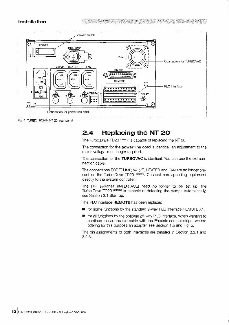
Fig. 4 TURBOTRONIK NT 20. rear panel
2.4 Replacing the NT 20 The TurboDrive T020 classic is capable of replacing the NT 20.
The connection for the power line cord is identical, an adjustment to the mains voltage is no longer required.
The connection for the TURBOVAC is identical. You can use the old connection cable.
The connections FOREPUMp, VALVE, HEATER and FAN are no longer present on the TurboDrive T020 classic. Connect corresponding equipment directly to the system controller.
The OIP switches (INTERFACE) need no longer to be set up, the TurboDrive T020 classic is capable of detecting the pumps automatically, see Section 3.1 Start up.
The PLC interface REMOTE has been replaced
III for some functions by the standard 9-way PLC interface REMOTE X1 .
III for all functions by the optional 25-way PLC interface. When wanting to continue to use the old cable with the Phoenix contact strips, we are offering for this purpose an adapter, see Section 1.5 and Fig. 5.
The pin assignments of both interfaces are detailed in Section 3.2.1 and 3.2.5.
10 I GA05228_0302 - 08/2006 - © Leybold Vacuum
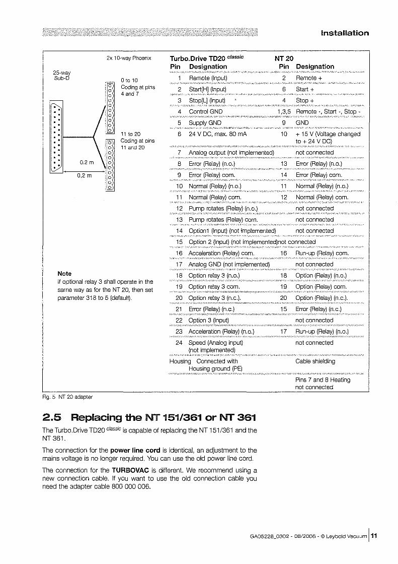
25-way Sub-O
Note
0.2 m
0,2 m
2x 10-way Phoenix
a a a a a
0 0 a a 0
o to 10 Coding at pins 4 and 7
11 to 20 Coding at pins 11 and 20
If optional relay 3 shall operate in the same way as for the NT 20, then set parameter 318 to 5 (default).
Fig. 5 NT 20 adapter
Installation
Turbo.Drive TD20 classic
Pin Designation NT 20
<",,,,,,,~",,,,, "
2 StalifHI (Input)
3
4 Control GND
Pin Designation
2 Remote +
6 Start +
4 +
1,3,5 Remote -, Start -,
10 + 15 V (Voltage changed to + 24 V .•. . ... " .................... .
7 not connected
10 11
11 12 Normal (Relay) com . .......... '~M •• ''''' •••• ~ ••••••.• ~ .• · ..•....••.•••.•••••• ..•• ~ ••••••.••••••••.•..
12 not connected
13 not connected
14 Option1 (Input) (not implemented) not connected
15 Option 2 (Input)(~~:implemented)not connected
16 com. 16 Run-up (Relay) com.
:1Ij7:~~'~;~';~:N~;;~~;i~;;'~;~;;;;;'~; _.- not connected
18 Option relay 3 (n.o.)
20 Option relay 3 (n.c.).
21
22
23 Acceleration (Relay) (n.o.)
24 Speed (Analog input)
Housing Connected with
18 Option (Relay) (n.o.)
20 Option (Relay) (n.c.).
15 Error
not connected
17 Run-up (Relay) (n.o.)
not connected
Cable shielding
Pins 7 and 8 Heating not connected
2.5 Replacing the NT 151/361 or NT 361 The Turbo.Drive TD20 classic is capable of replacing the NT 151/361 and the NT 361.
The connection for the power line cord is identical, an adjustment to the mains voltage is no longer required. You can use the old power line cord.
The connection for the TURBOVAC is different. We recommend using a new connection cable. If you want to use the old connection cable you need the adapter cable 800 000 006.
GA05228_0302 - 08/2006 - © Leybold Vacuum 111
Installation
Turbo.Drive T020 classic
Power line cord
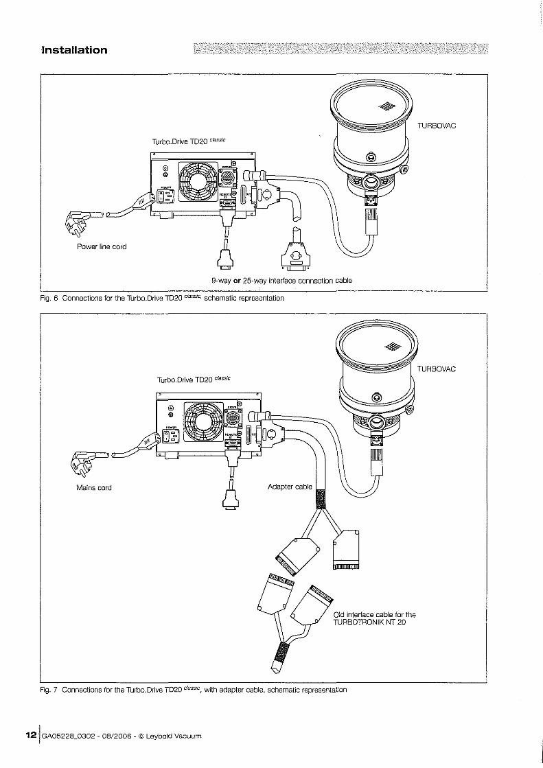
9-way or 25-way interface connection cable
Fig. 6 Connections for the Turbo.Drive T020 classic, schematic representation
Turbo.Drive T020 classic
Mains cord
Old interface cable for the TURBOTRONIK NT 20
Fig. 7 Connections for the Turbo.Drive T020 classic, with adapter cable, schematic representation
121 GA05228_0302 - 08/2006 - © Leybold Vacuum
TURBOVAC
TURBOVAC
,..--, • .JLeyboid
vacuum
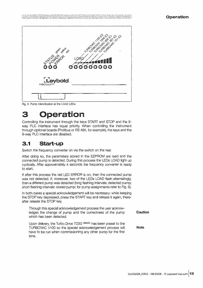
II Fig. 6 Pump identification at the LOAD LEOs
3 Operation Controlling the instrument through the keys START and STOP and the 9-way PLC interface has equal priority. When controlling the instrument through optional boards (Profibus or RS 485, for example), the keys and the g-way PLC interface are disabled.
3.1 Start-up Switch the frequency converter on via the switch on the rear.
After doing so, the parameters stored in the EEPROM are read and the connected pump is detected. During this process the LEDs LOAD light up cyclically. After approximately 4 seconds the frequency converter is ready to start.
If after this process the red LED ERROR is on, then the connected pump was not detected. If, moreover, two of the LEDs LOAD flash alternatingly, then a different pump was detected (long flashing intervals: detected pump; short fiashing intervals: stored pump; for pump assignments refer to Fig. 6).
In both cases a special acknowledgement will be necessary: while keeping the STOP key depressed, press the START key and release it again, thereafter release the STOP key.
Through this special acknowledgement process the user acknowledges the change of pump and the correctness of the pump which has been detected.
Upon delivery, the TurboDrive TD20 classic has been preset to the TURBOVAC 1100 so the special acknowledgement process will have to be run when commissioning any other pump for the first time.
Operation
Caution
Note
GA05228_0302 - 08/2006 ~ © Leybold Vacuum \13
Operation
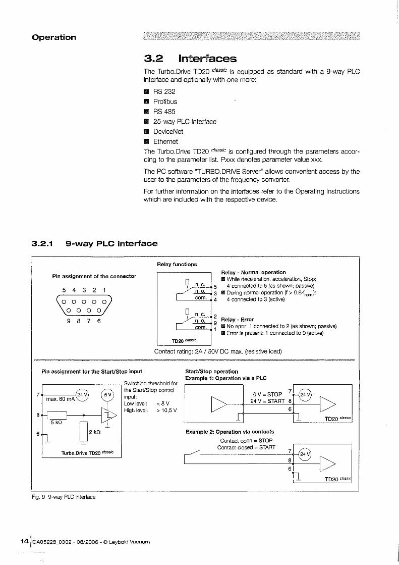
3.2 Interlaces The Turbo.Drive TD20 classic is equipped as standard with a 9-way PLC interface and optionally with one more:
l1li RS 232
l1li Profibus
l1li RS 485
III 25-way PLC interface
III DeviceNet
III Ethernet
The Turbo.Drive TD20 classic is configured through the parameters according to the parameter list. Pxxx denotes parameter value xxx.
The PC software "TURBO DRIVE Server" allows convenient access by the user to the parameters of the frequency converter.
For further information on the interfaces refer to the Operating Instructions which are included with the respective device.
3.2.1 9-way PLC interface
Relay functions
Pin assignment of the connector
Q n.c. Js Relay - Normal operation JIll While deceleration, acceleration, Stop:
4 connected to 5 (as shown; passive) III During normal operation (f> O.8·fnom):
4 connected to 3 (active)
5 4 3 2
\(00000009 9 8 7 6
Pin assignment for the Start/Stop input
-/ffi3 ~4
Q n. c. 12 ~ n.o. 9 I com. 1
TD20 classic
Relay - Error III No error: 1 connected to 2 (as shown; passive) II Error is present: 1 connected to 9 (active)
Contact rating: 2A / 50V DC max. (resistive load)
Start/Stop operation Example 1: Operation via a PLC
,-_________ -, Switching threshold for the Start/Stop control
7. Q 5V I max.BomAV
:kSkQ
input: Low level: High level:
<BV > 10,S V
Turbo.Drive TD20 classic
Fig. 9 g~way PLC interface
141 GA05228_0302 - 08/2006 - © Leybold Vacuum
OV = STOP 24 V= START
Example 2: Operation via contacts
Contact open = STOP Contact closed = START
71 Q BIO 6
TD20 classIc
:1 8 [> il TD20 classIc
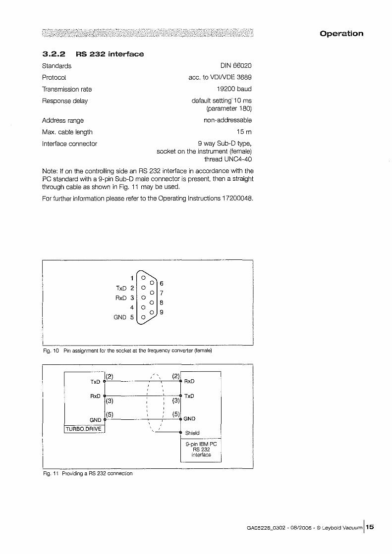
3.2.2 RS 232 interface
Standards DIN 66020
Protocol acc. to VDINDE 3689
Transmission rate
Response delay
Address range
Max. cable length
Interface connector
19200 baud
default setting 10 ms (parameter 180)
non-addressable
15 m
9 way Sub-D type, socket on the instrument (female)
thread UNC4-40
Note: If on the controlling side an RS 232 interface in accordance with the PC standard with a 9-pin Sub-D male connector is present, then a straight through cable as shown in Fig. 11 may be used.
For further information please refer to the Operating Instructions 17200048.
1~ 0 6
TxD 2 0 0 7
RxD 3 0 0 8
4 0 0 9
GND 5 Y
Fig. 10 Pin assignment for the socket at the frequency converter (female)
(2) ~ . (2) , , TxD RxD , , , , RxD
, TxD
(3) , ,
(3) , I , ,
(5) , ,
(5) , , GND , GND , ,
TURBO. DRIVE , , .
Shield
9-pin IBM PC RS 232 interface
Fig. 11 Providing a RS 232 connection
Operation
GA05228_0302 ~ 08/2006 . © Leybold Vacuum 115
Operation
161 GA05228_0302 - 08/2006 - © Leybold
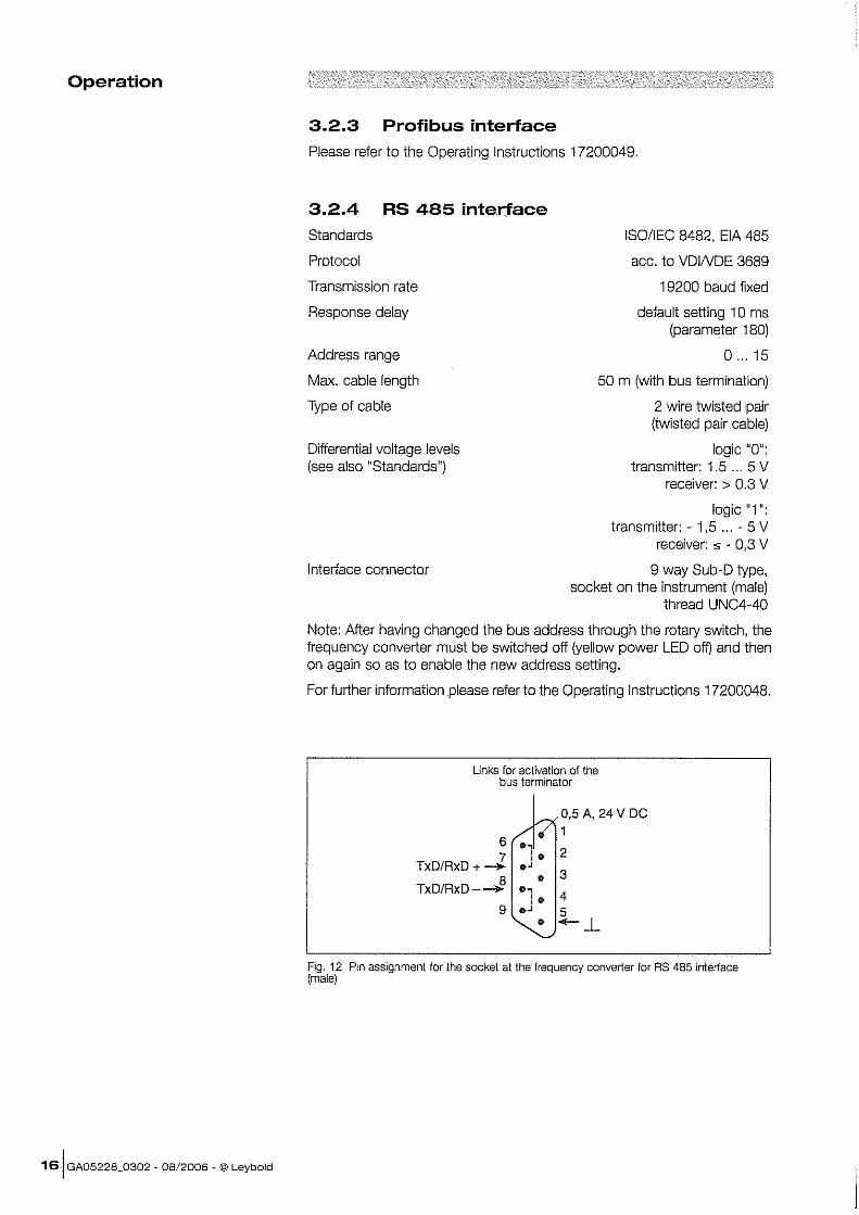
3.2.3 Profibus interface
Please refer to the Operating Instructions 17200049.
3.2.4 RS 485 interface
Standards ISO/IEC 8482, EIA 485
Protocol acc. to VDINDE 3689
Transmission rate
Response delay
Address range
Max. cable length
Type of cable
Differential voltage levels (see also "Standards")
I nterface connector
19200 baud fixed
default setting 10 ms (parameter 180)
0 ... 15
50 m (with bus termination)
2 wire twisted pair (twisted pair cable)
logic nOll: transmitter: 1.5 ... 5 V
receiver: > 0.3 V
logic "1": transmitter: - 1,5 ... - 5 V
receiver: " - 0,3 V
9 way Sub-D type, socket on the instrument (male)
thread UNC4-40
Note: After having changed the bus address through the rotary switch, the frequency converter must be switched off (yellow power LED off) and then on again so as to enable the new address setting.
For further information please refer to the Operating Instructions 17200048.
Unks for activation of the bus terminator
V? 0,5 A, 24 V DC
/1_ 1 6 0
7 :. 2 TxD/RxD + - ". 3
8 • TxD/RxD-_ '" 4 :.
9 • .J 5 ~--L
Fig. 12 Pin assignment for the socket at the frequency converter for RS 485 interiace (male)
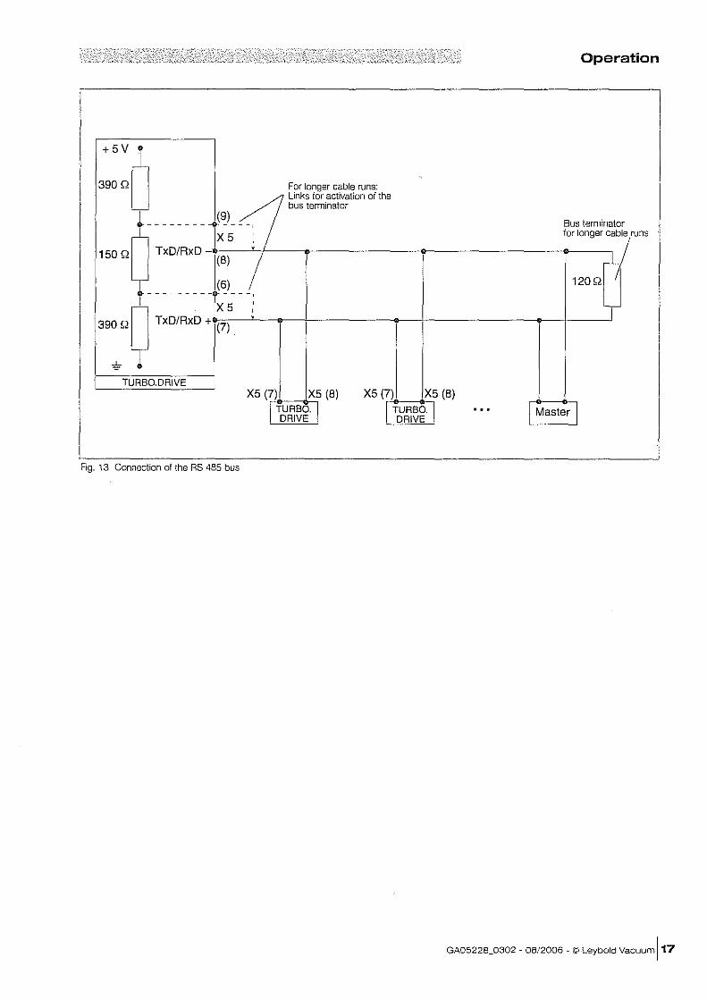
Operation
Bus terminator for longer cable runs
~ 120Q I
TURBODRIVE X5 (7) X5 (8)
I TURBO. I DRIVE
X5 (7C'<)D:=~X:..:.;5 (8)
I TURBO. I DRIVE
Fig. 13 Connection of the RS 485 bus
GA05228_0302 fi OB/2006 - © Leybold Vacuum ]17
Operation
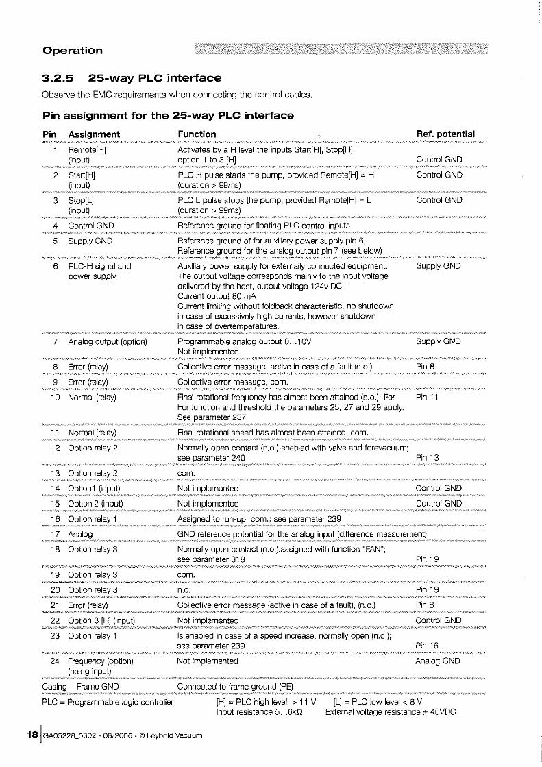
3.2.5 25-way PLC interface
Observe the EMC requirements when connecting the control cables.
Pin assignment for the 25-way PLC interface
Pin Assignment '»"~''''~'''.'''',". __ ,.,"_''_ ,,, •. ".'.'-''"Wk._<c_._
Remote[H]
2 Start[H]
3 Stop[L]
4 Control GND
5 Supply GND
6 PLC-H signal and power supply
7 Analog output (option)
8 Error
9 Error
10 Normal (relay)
11 Normal
12 Option relay 2
13
14
15
16
17
18 Option relay 3
19
20
21
22
23 Option relay 1
24 Frequency (option)
PLC = Programmable logic controller
Function
Activates by a H level the inputs Start[H], Stop[H], 1 to 3
PLC H pulse starts the pump, provided Remote[H] = H (duration>
PLC L pulse stops the pump, provided Remote[H] = L
Reference
Reference ground of for auxiliary power supply pin 6, Reference for the 7 (see below)
Auxiliary power supply for externally connected equipment. The output voltage corresponds mainly to the input voltage delivered by the host, output voltage 124v DC Current output 80 mA Current limiting without fold back characteristic, no shutdown in case of excessively high currents, however shutdown in case of ov"rtElmr18n3tures.
Programmable analog output 0 ... 10V Not imrllennen,jerl
Collective error active in case of a fault
Collective error com.
Ref. potential
Control GND
Control GND
Control GND
Supply GND
Supply GND
Pin 8
Final rotational frequency has almost been attained (n.o.). For Pin 11 For function and threshold the parameters 25, 27 and 29 apply. See 237
Final rotational has almost been attained, com.
Normally open contact (n.o.) enabled with valve and forevacuum; see 240 Pin 13
com.
Not implemented Control GND
Not Control GND
to com.; see parameter 239
GND reference for the (difference
Normally open contact (n.o.).assigned with function "FAN"; see 318 Pin 19
com.
n.c. Pin 19
Collective error (active in case of a fault), (n.c.) Pin 8
Not imrllen1enterl Control GND
Is enabled in case of a speed increase, normally open (n.o.); see 239 Pin 16
Not implemented Analog GND
Connected to frame
[H] = PLC high level > 11 V Input resistance 5 ... 6kQ
[L] = PLC low level < 8 V External voltage resistance ± 40VDC
181 GA05228_0302 - 08/2006 ~ © Leybold Vacuum
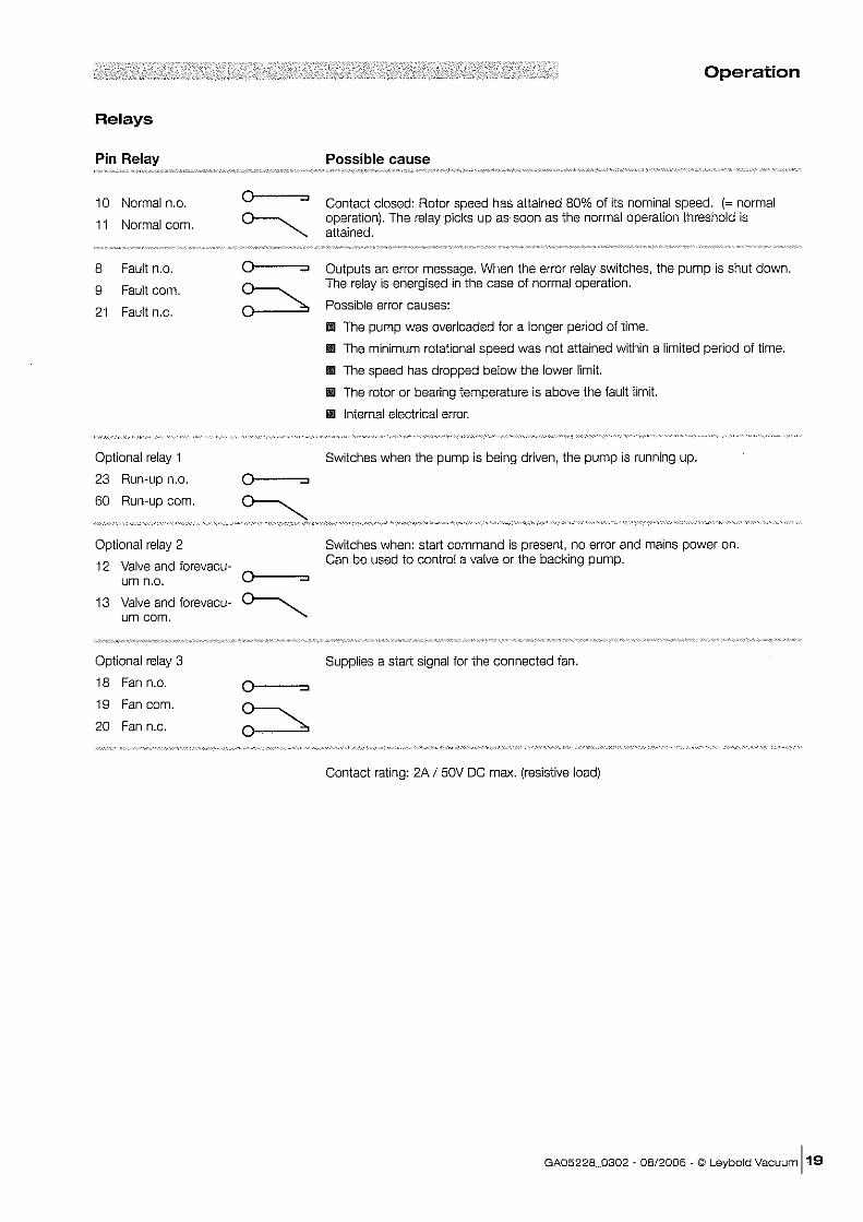
Relays
Pin Relay
10 Normal n.o.
11 Normal com.
8 Fault n.o.
9 Fault com.
21 Fault n.C.
Optional relay 1
23 Run-up n.o.
60 Run-up com.
Optional relay 2
12 Valve and forevacu-urn n.o.
13 Valve and forevacu-urn com.
Optional relay 3
18 Fan n.o.
19 Fan com.
20 Fan n.c.
0 ...,
~ 0 ...,
~
0 ...,
0 ...,
~
Operation
Possible cause
Contact closed: Rotor speed has attained 80% of its nominal speed. (= normal operation). The relay picks up as soon as the normal operation threshold is attained.
Outputs an error message. When the error relay switches, the pump is shut down . The relay is energised in the case of normal operation.
Possible error causes:
l1li The pump was overloaded for a longer period of time.
IIiII The minimum rotational speed was not attained within a limited period of time.
III The speed has dropped below the lower limit.
III The rotor or bearing temperature is above the fault limit.
II Internal electrical error.
Switches when the pump is being driven, the pump is running up.
Switches when: start command is present, no error and mains power on. Can be used to control a valve or the backing pump.
Supplies a start signal for the connected fan.
Contact rating: 2A I 50V DC max. (resistive load)
GA05228_0302 - 08/2006 - © Leybold Vacuum 119
Operation
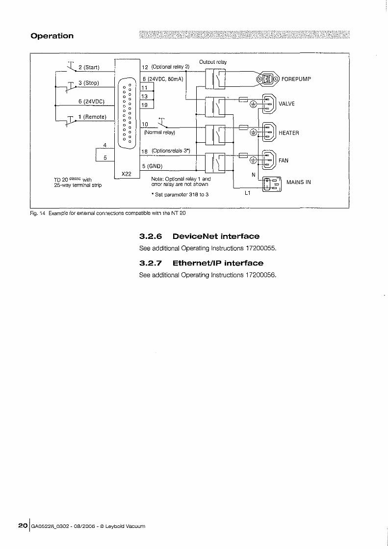
2 (Start) Output relay
12 (Optional relay 2)
3 (Stop) 6 (24VDC, BOmA)
11
• FOREPUMP
6 (24VDC)
1 (Remote)
TD 20 classic with 25-way terminal strip
4
5
X22
,uJ::::l-~~
13
19
10
(Normal relay)
18 (Optionsrelais 3*)
5 (GND)
Note: Optional relay 1 and error relay are not shown
• Set parameter 318 to 3
Fig. 14 Example for external connections compatible with the NT 20
3.2.6 DeviceNet interface
See additional Operating Instructions 17200055.
3.2.7 EthernetilP interface
See additional Operating Instructions 17200056.
20 I GA05228_0302 - 08/2006 - © Leybold Vacuum
MAINS IN
Operation
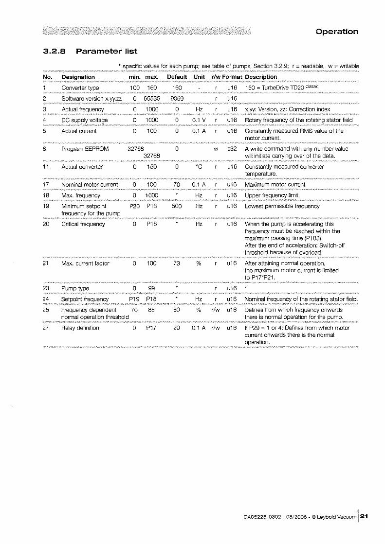
3.2.8 Parameter list
* values for each see table of Section 3.2.9; r = readable, w = writable
No. , ~!~,~,~~,~"~,~,~~~'''''''''''''' min. max. Default Unit r/w Format Description
''''~,'",'7'';r",,'Z'',"" "Z_"""'/'"''''"/>; __ ''''' _';!_"'''''''''~L'''''',-'''',,,.,,",,,,,,,; ",_-.-'~";'wmP,""A_ -_""",,,_-_~_-
Converter 100 160 160 u16 160 = TurbeDrive T020 classic
2 0 65535 9059 b16
3 Actual frequency 0 1000 0 Hz u16 Version, zz: Correction index
4 DC 0 1000 0 0.1 V u16 frequency of the rotating stator field
5 Actual current 0 100 0 0.1 A u16 Constantly measured RMS value of the motor current.
8 Program EEPROM -32768 0 w s32 A write command with any number value 32768 will initiate over of the data.
11 Actual converter 0 150 0 'C u16 Constantly measured converter
17 Nominal motor current 0 100 70 0.1 A u16 Maximum motor current
18 Max. frequency 0 1000 Hz u16 Upper frequency limit.
19 P20 P18 500 Hz u16 Lowest permissible frequency
20 Critical frequency 0 P18 Hz u16 When the pump is accelerating this frequency must be reached within the maximum passing time (P183). After the end of acceleration: Switch-off threshold because of overload.
21 Max. current factor 0 100 73 % u16 After attaining normal operation, the maximum motor current is limited to P1rp21.
23 0 99 u16
24 P19 P18 Hz r u16 Nominal of the stator field.
25 Frequency dependent 70 85 80 % r/w u16 Defines from which frequency onwards normal threshold there is normal for the
27 Relay definition 0 P17 20 0.1 A r/w u16 If P29 = 1 or 4: Defines from which motor current onwards there is the normal
GA0522B_0302 - 08/2006 - © Leybold Vacuum 121
Operation
No. Designation min. max. Default Unit r/w Format Description
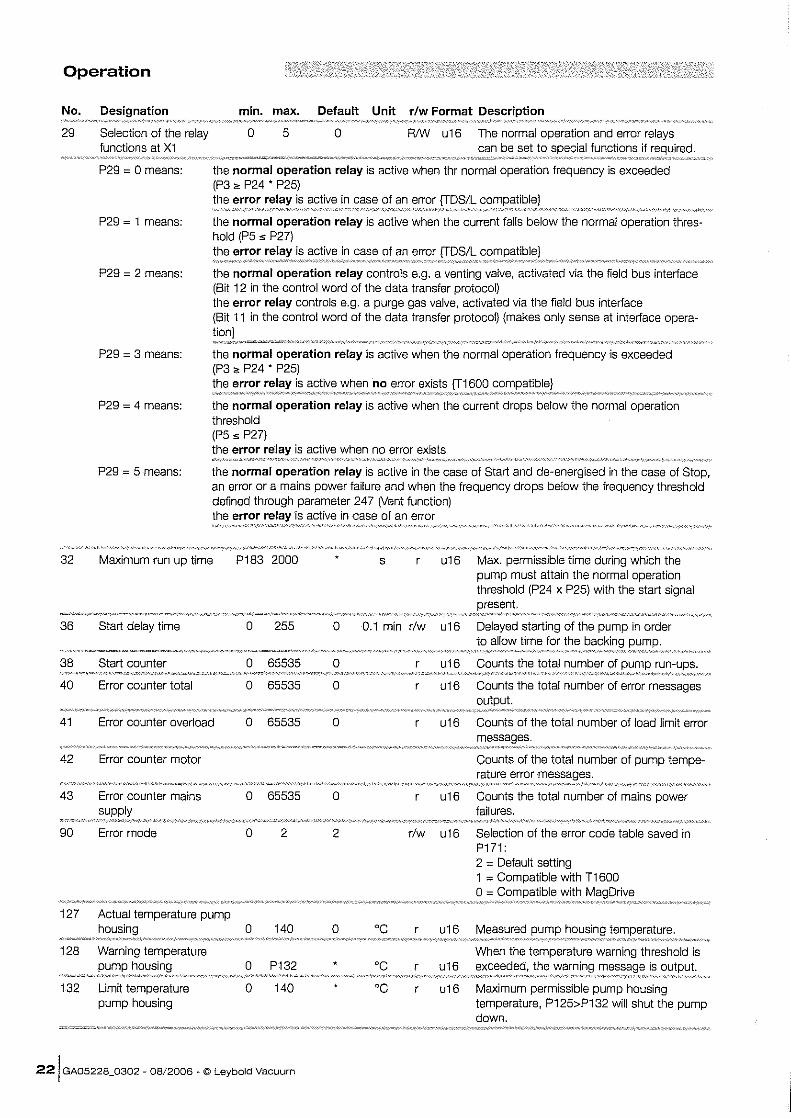
29 Selection olthe relay 0 5 0 RIW u 16 The normal operation and error relays functions at XI can be set to functions if reCJUlreo.
~"~""""""'~""""""""'~"~~~~"~'~"'~~" .•..... ~~~ ... ~.~ ....
32
36
38
40
41
42
43
90
127
128
132
P29 = 0 means:
P29 = 1 means:
P29 = 2 means:
P29 = 3 means:
P29 = 4 means:
P29 = 5 means:
the normal operation relay is active when thr normal operation frequency is exceeded (P3 " P24 • P25) the error is active in case of an error
the normal operation relay is active when the current falls below the normal operation thres· hold (P5 " P27) the error is active in case of an error
the normal operation relay controls e.g. a venting valve, activated via the field bus interiace (Bit 12 in the control word of the data transfer protocol) the error relay controls e.g. a purge gas valve, activated via the field bus interiace (Bit 11 in the control word of the data transfer protocol) (makes only sense at interiace opera-
the normal operation relay is active when the normal operation frequency is exceeded (P3 " P24 • P25) the error relay is active when no error exists 600
the normal operation relay is active when the current drops below the normal operation threshold (P5" P27) the error is active when no error exists
the normal operation relay is active in the case of Start and de-energised in the case of Stop, an error or a mains power failure and when the frequency drops below the frequency threshold defined through parameter 247 (Vent function) the error is active in case of an error
Maximum run up time P183 2000 s u16 Max. permissible time during which the pump must attain the normal operation threshold (P24 x P25) with the start signal
Start delay time 0 255 0 0.1 min r/w u16 Delayed starting of the pump in order to allow time for the
Start counter 0 65535 0 r u16 Counts the total number of
Error counter total 0 65535 0 u16 Counts the total number of error messages
Error counter overload 0 65535 0 u16 Counts of the total number of load limit error
Error counter motor Counts of the total number of pump tempe-rature error
Error counter mains 0 65535 0 u16 Counts the total number of mains power failures.
Error mode 0 2 2 r/w u16 Selection of the error code table saved in PHI: 2 = Default setting 1 = Compatible with T1600 0 with
Actual temperature pump 0 140 0 'C u16 Measured
Warning temperature When the temperature warning threshold is 0 P132 'C r u16 exceeded, the is
Limit temperature 0 140 • 'C u16 Maximum permissible pump housing pump housing temperature, P125>P132 will shut the pump
down . =,=,,7.',"" ~.~""/'",,",w-,,-.~.·p,_,,.~= • "'X',!",-"Y'_',,;c> ,' ___ -___ "",-''';,,,","'c''"''"'''_,_·_''""'~h'~ij~''/,',''-, "'''''''/.~/,"''''--'' .- ~·~",#"!",,,,;.,WA9!'''~''{'''''''' __
221 GA05228_0302 - 08/2006 ~ © Leybold Vacuum
Operation
No. Designation min. max. Default Unit r/w Format Description 'N,' •• /,,, __ ,,,",C-".' ,
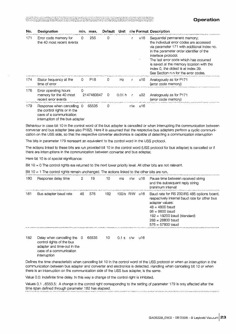
171 Error code memory for 0 255 0 u16 Sequential permanent memory; the 40 most recent events the individual error codes are accessed
via parameter 171 with additional index no. in the parameter order identifier of the interface protocol. The last error code which has occurred is saved at the memory location with the index O. the oldest is at index 39. See Section n.n for the error codes.
174 Stator frequency at the 0 P18 0 Hz u16 Analogously as for P171 time of error code
176 Error operating hours 0 memory for the 40 most 2147483647 0 0.01 h r u32 Analogously as for P171 recent error events (error code memory)
179 Response when cancelling 0 65535 0 rlw u16 the control rights or in the case of a communication interruption of the bus adapter
Behaviour in case bit 10 in the control word of the bus adapter is cancelled or when interrupting the communication between converter and bus adapter (see also P182). Here it is assumed that the respective bus adapters perform a cyclic communication on the USS side. so that the respective converter electronics is capable of detecting a communication interruption
The bits in parameter 179 represent an equivalent to the control word in the USS protocol.
The actions linked to these bits are run provided bit 10 in the control word (USS protocol for bus adapter) is cancelled or if there are interruptions in the communication between converter and bus adapter.
Here bit 10 is of special significance:
Bit 10 = 0 The control rights are returned to the next lower priority level. All other bits are not relevant.
Bit 10 = 1 The control Inchanol,d. The actions linked to the other bits are run. ~··~.~ ••.• ~~ ••. ~.~ .•••••.. ~ ••• = .. ~ •. ~ .•..• :o.... . .............•..•..•••.•••••••••••. ~ ................... . 180 Response delay time 2 19
181 Bus adapter baud rate 48 576
182 Delay when cancelling the 0 65535 control rights of the bus adapter and time-out in the case of a communication interruption
10
192
10
ms r/w u16 Pause time between received string and the subsequent reply string (minimum interval
100ls RNV u16 Baud rate for RS 232/RS 485 options board. respectively internal baud rate for other bus adapter values:
0.1 s rlw u16
48 = 4800 baud 96 = 9600 baud 192 = 19200 baud (standard) 288 = 28800 baud 576 = 57600 baud
Defines the time characteristic when cancelling bit 10 in the control word of the USS protocol or when an interruption in the communication between bus adapter and converter and electronics is detected. Handling when cancelling bit 10 or when there is an interruption on the communication side of the USS bus adapter. is the same.
Value 0.0: Indefinite time delay. In this way a change of the control right is inhibited.
Values 0.1 .. 6553.5: A change in the control right corresponding to the setting of parameter 179 is only effected after the time defined 182 has
GA05228_0302 - 08/2006 - © Leybold Vacuum 123
Operation
No. Designation min. max. Default Unit r/w Format
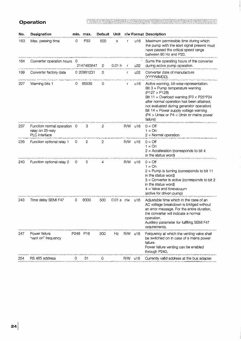
183 Max, passing time 0 P32 500 s u16 Maximum permissible time during which the pump with the start signal present must have passed the critical speed range between 60 Hz and P20,
184 Converter operation hours 0 Sums the operating hours of the converter 2147483647 0 0,01 h u32 active operation.
199 Converter factory date o 20991231 0 u32 Converter date of manufacture
227 Warning bits 1 0 65535 0 u16 Active warning, bit-wise representation: Bit 3 ~ Pump temperature warning (P127 > P128) Bit 11 ~ Overload warning (P3 < P25"P24 after normal operation has been attained, not evaluated during generator operation) Bit 14 ~ Power supply voltage warning (P4 > Urnax or P4 < Umin or mains power
237 Function normal operation 0 3 2 RIW u16 o ~ Off relay on 25-way 1 ~ On PLC interface 2 ~ Norrnal
239 Function optional relay 1 0 2 2 RIW u16 o ~ Off 1 ~ On 2 ~ Acceleration (corresponds to bit 4 in the status
240 Function optional relay 2 0 5 4 RIW u16 o ~ Off 1 ~ On 2 ~ Purnp is turning (corresponds to bit 11 in the status word) 3 ~ Converter is active (corresponds to bit 2 in the status word) 4 ~ Valve and forevacuurn
243 Time delay SEMI F47 0 6000 500 0,01 s r/w u16 Adjustable time which in the case of an AC voltage breakdown is bridged without an error message. For the entire duration, the converter will indicate a normal operation, Auxiliary pararneter for fulfilling SEMI F47
247 Power failure P248 P18 300 Hz RIW u16 Frequency at which the venting valve shall "vent on" frequency be switched on in case of a mains power
failure, Power failure venting can be enabled
P240,
254 RS 485 address 0 31 0 RIW u16 valid address at the bus
Operation
No. Designation min. max. Default Unit r/w Format Description '~·c",·o/<J,,"'m""'~·'·"·'. v _" •• _MW._/." ••
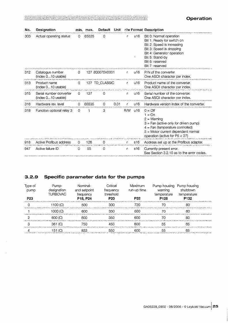
303 Actual operating status 0 65535 0 u16 Bit 0: Normal operation Bit 1: Ready for switch on Bit 2: Speed is increasing Bit 3: Speed is dropping Bit 4: Generator operation Bit 5: Stand-by Bit 6: reserved Bit 7: reserved
312 0 127 800075VOO01 u16 PIN of the converter. One ASCII character per index.
313 Product name 0 127 TO_CLASSIC u16 Product name of the converter. (Index 0 ... 10 One ASCII character per index.
315 Seria! number converter 0 127 0 u16 Serial number of the converter. (Index 0 ... 10 One ASCII character index.
316 Hardware rev. level 0 65535 0 0.01 u16 Hardware version index of the converter.
318 Function optional relay 3 0 3 RNI u16 o ~ Off 1 ~ On 2 ~ Warning 3 ~ Fan (active only for driven pump) 4 ~ Fan (temperature controlled) 5 ~ Motor current dependent normal
(active for P5 <
918 Active Profibus address 0 126 0 s16 Address set
947 Active failure 10 0 55 0 s16 Currently present error. See Section 3.2.10 as to the error codes.
3.2.9 Specific parameter data for the pumps
Type of Pump- Nominal- Critical Maximum Pump housin9 Pump housing pump designation and setpoint frequency run-up time warning shutdown
TURBOVAC frequency threshold temperature temperature P23 P18, P24 P20 P32 P128 P132
0 300 720 70 80
350 600 70 80
2 350 600 70 80
3 450 600 55 65
55
GA05228_0302 ~ 08/2006 ~ © Leybold Vacuum 125
Operation
3.2.10 Error messages
No. Shutdown LED
0 No No error
No Overload warning
3 No Power supply voltage error
4 Yes 5 Converter error
6 Yes 4 Overload error
7 Yes 3 Run-up time error
8 Yes 2 Pump error
"'''"',',''",',v,,,",'=,,,,,",,''''_''}0'',''--''''<'':¢='''''''·'-""""-,,,,,,_,-",,,",PP'-"'. " '/,Y-"~_'Y'W"""W"
10 Yes 6 error
16 Yes 4 Overload dUration error
17 Yes Motor current error
19 Yes 3 Pass-through time error
43 Yes 8 Internal error
60 Yes 7 Hardware monitoring
62 No
230 to Yes 7 Internal error 251
261 GA05228_0302 - 08/2006 . © Leybold Vacuum
Condition
P3 < P25"P24 (after normal operation has been attained)
Power supply voltage failure during active pump
P11 > limit threshold converter temperature.
P3 < P20 after normal was attained.
P3 < P24"P25 alter P32 has elapsed with start
Pump could not be identified or no pump has been connected.
P127> P132 or switch (Xl
P3 < P25"P24 of than P32.
No motor current or motor current too low.
60 Hz < P3 < P20 alter P183 has elapsed with the start signal
Short -circuit within the motor or connecting cable
P127>P128
Error within the converter or external voltage applied to the inputs
3.3 Start-up of the TURBOVAC Press the START key.
The STATUS LED flashes during acceleration. The LED chain indicates the increasing speed with one LED each. When 80% of the target speed has been reached, the LED STATUS remains on continuously.
During normal operation the row of LEDs will indicate the amount of power taken up by the TURBOVAC.
3.4 Operation During NORMAL operation, the LED STATUS lights and the LED chain shows, starting at the bottom and moving upwards, the current consum-ed.
If the target speed of the TURBOVAC cannot be maintained during normal operation due to overloading (pressure, excessive TURBOVAC or Turbo Drive classic temperature), the LED ERROR flashes.
The mode is not a failure, but can result in a shut down depending on the cause of overload, e.g. if the temperature continues to rise.
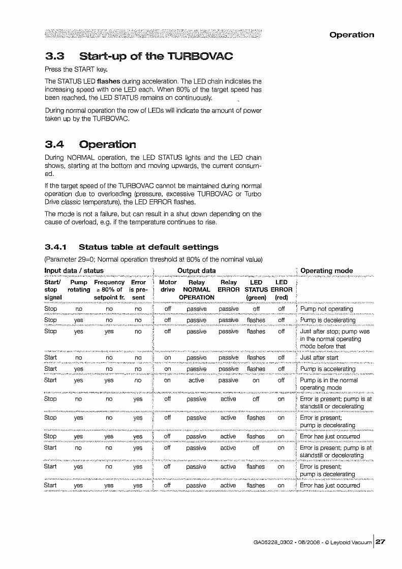
3.4.1 Status table at default settings
(Parameter 29~0; Normal operation threshold at 80% of the nominal value)
data I status data
Start! Pump Frequency Error Motor Relay Relay stop rotating ~ 80% of is pre~ drive NORMAL ERROR
setpoint fro sent OPERATION
no no off
no no off flashes
Stop yes yes no off passive passive flashes
Start no no no on flashes
Start no no on flashes
Start yes yes no on active passive on
Stop no no yes off passive active off
Stop yes no yes off passive active flashes
off active flashes
Start no no yes off passive active off
Start yes no yes off passive active flashes
Start yes yes yes off passive active flashes
Operation
Operating mode
not
off is
off
off
off is
off
on Error is present; pump is at standstill or
on is
on
on Error is present; pump is at standstill or
on Error is present; is
on
GA05228_0302 ~ 08/2006 - © Leybold Vacuum 127
Operation/Maintenance
Warning
Warning
3.5 Shut-down of the TURBOVAC Press the STOP key.
While the pump runs down, the STATUS LED flashes. The TURBOVAC runs down until it stands still.
The row of LEDs indicates the decrease in speed through one LED each. The rotational speed can only be indicated down to approximately 250 Hz, i.e. the STATUS LED goes out before the pump has come to a standstill.
Before working on the pump make sure that the pump is at standstill.
3.6 Shut-down of the Turbo.Drive TD20 classic
Press the STOP key.
Set the mains switch on the rear to the position "0".
4 Maintenance The converter essentially requires no servicing since it contains no components which could be adjusted.
Depending on the installation particulars and the ambient conditions, the converter may collect grime (dust, moisture) on the inside. Such contamination can lead to malfunctions, overheating or short circuits and will have to be avoided to the maximum extent possible. The Leybold Service Department can clean the converter. We recommend adhering to a cleaning interval of about three years.
Only qualified personnel or the Leybold Service Department may carry out work on the frequency converter.
Potentially fatal voltages are present inside the frequency converter.
Open the frequency converter only after it has been isolated from the mains power supply.
The converter contains components which could be damaged by electrostatic discharges.
28 I GA05228_0302 - 08/2006 - © Leybold Vacuum
Troubleshooting
5 Troubleshooting When a malfunction occurs, the TURBOVAC is no longer driven and a failure code is indicated.
The red LED ERROR lights permanently and one green LED within the chain fiashes.
After you have eliminated the cause of the failure, you can reset the malfunction signal with the STOP command (key or remote control).
Only qualified personnel or the Leybold Service Department may carry out work on the frequency converter.
Potentially fatal voltages are present inside the frequency converter.
Open the frequency converter only after it has been isolated from the mains power supply.
Symptom
Turbomolecular pump produces strong running noises and vibrations.
Turbomolecular pump does not attain its ultimate pressure,
The running pump cannot be stopped through the keys or X1.
Probable Cause
Rotor imbalance.
Defective bearing
Defective measuring instrument.
Contaminated gauge head.
Leak at the apparatus, lines or the pump.
Contaminated pump.
Inadequate pumping speed of the backing pump or ultimate pressure is too high.
Incorrectly programmed frequency parameters.
The pump was started through the serial interface.
Warning
Remedy
Have the rotor balanced.
Replace the bearing.
Check the measuring instrument.
Clean or replace the gauge head.
Leak search.
Clean the pump.
Check the ultimate pressure supplied via the backing pump; if required installed a larger backing pump.
Check the parameters.
Disconnect the AC supply or provide a serial link and stop through bus.
GA05228_0302 - 08/2006 - © Leybold Vacuum 129
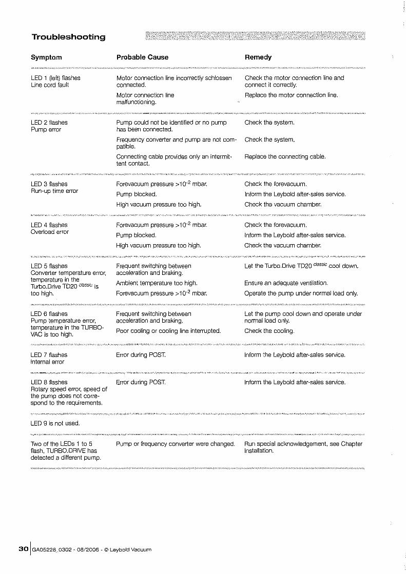
Troubleshooting
Symptom
LED 1 (left) flashes Line cord fault
LED 2 flashes Pump error
LED 3 flashes Run-up time error
LED 4 flashes Overload error
LED 5 flashes Converter temperature error, temperature in the Turbo.Drive TD20 classic is too high.
LED 6 flashes Pump temperature error, temperature in the TURBOVAC is too high.
LED 7 flashes Internal error
LED 8 flashes Rotary speed error, speed of the pump does not correspond to the reqUirements.
LED g is not used.
Two of the LEDs 1 to 5 flash, TURBO DRIVE has detected a different pump.
Probable Cause
Motor connection line incorrectly schlossen connected.
Motor connection line malfunctioning.
Pump could not be identified or no pump has been connected.
Remedy
Check the motor connection line and connect it correctly.
Replace the motor connection line.
Check the system.
Frequency converter and pump are not com- Check the system. patible.
Connecting cable provides only an intermit- Replace the connecting cable. tent contact.
Forevacuum pressure> 10.2 mbar.
Pump blocked.
High vacuum pressure too high.
Forevacuum pressure> 10-2 mbar.
Pump blocked.
High vacuum pressure too high.
Frequent switching between acceleration and braking.
Ambient temperature too high.
Forevacuum pressure> 10-2 mbar.
Frequent switching between acceleration and braking.
Poor cooling or cooling line interrupted.
Error during POST.
Error during POST.
Check the forevacuum.
Inform the Leybold after-sales service.
Check the vacuum chamber.
Check the forevacuum.
Inform the Leybold after-sales service.
Check the vacuum chamber.
Let the Turbo.Drive T020 classic cool down.
Ensure an adequate ventilation.
Operate the pump under normal load only.
Let the pump cool down and operate under nonmal load only.
Check the cooling.
Inform the Leybold after-sales service.
Inform the Leybold after-sales service.
Pump or frequency converter were changed. Run special acknowledgement, see Chapter Installation.
30 I GA05228_0302 - 08/2006 - © Leybold Vacuum
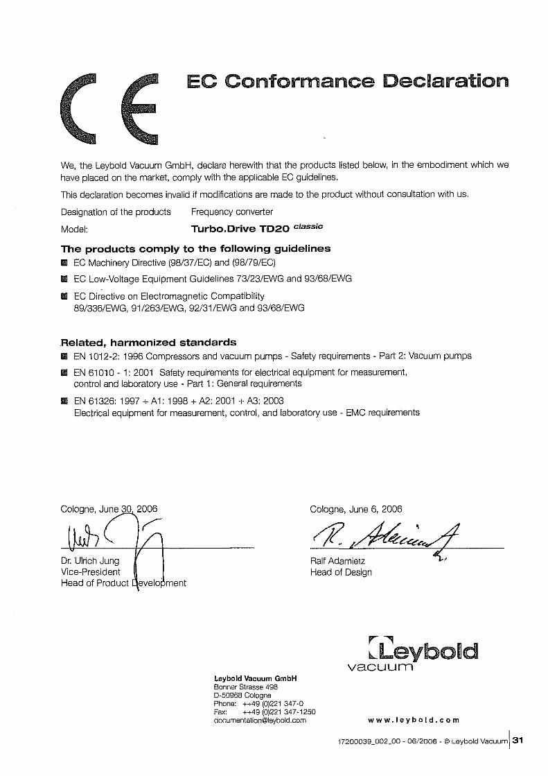
EC Conformance Declaration
We, the Leybold Vacuum GmbH, declare herewith that the products listed below, in the embodiment which we have placed on the market, comply with the applicable EC guidelines.
This declaration becomes invalid if modifications are made to the product without consultation with us.
Designation of the products
Model:
Frequency converter
Turbo.Drive TD20 classic
The products comply to the following guidelines l1li EC Machinery Directive (98/37/EC) and (98/79/EC)
l1li EC Low-Voltage Equipment Guidelines 73/23/EWG and 93/68/EWG
III EC Directive on Electromagnetic Compatibility 89/336/EWG, 91/263/EWG, 92/31/EWG and 93/68/EWG
Related, harmoni;zed standards l1li EN 1012-2: 1996 Compressors and vacuum pumps - Safety requirements - Part 2: Vacuum pumps
III EN 61010 - 1: 2001 Safety requirements for electrical equipment for measurement, control and laboratory use - Part 1: General requirements
l1li EN 61326: 1997 + A 1: 1998 + A2: 2001 + A3: 2003 Electrical equipment for measurement, control, and laboratory use - EMC requirements
Cologne, June 30 2006
Dr. Ulrich Jung Vice-President
~
Head of Product evelo' ment
Leybold Vacuum GmbH Bonner Strasse 498 0-50968 Cologne Phone: ++49 (01221 347-0
Cologne, June 6, 2006
"1:.m~?~4 Head of Design
r---, ~Leybold
vacuum
Fax: ++49 (01221347-1250 [email protected] www.Jeybold.com
17200039_002_00 - 06/2006 - © Leybold vacuum! 31
Sales and Service Net Worldwide
Germany
Leybold Vacuum GmbH Bonner Strasse 498 0-50968 Cologne Phone: +49-221-3471234 Fax: +49-221-3471245 [email protected]
LeyboJd Vacuum GmbH Sales Area North/East Branch office Berlin Buschkrugaliee 33 1. Obergeschoss 0-12359 Berlin Phone: +49-30-4356090 Fax: +49-30-43560910 [email protected]
Leybold Vacuum GmbH Sales Area South/Southwest Branch office Munic Send linger Strasse 7 0-80331 Munic Phone: +49-89·357 33 9-10 Fax: +49-89·357 33 9-33 [email protected] [email protected]
Leybold Vacuum GmbH Sales Area West Branch office Cologne Bonner Strasse 498 D-50968 Cologne Phone: +49-221-3471270 Fax: +49-221-3471291 [email protected]
Leybold Vacuum GmbH Service Center Emil-Hoffmann-StraBe 43 0-50996 Cologne-Suerth Phone: +49-221-3471439 Fax: +49-221-3471945 [email protected]
Leybold Vacuum GmbH Mobile after sales service Emil-Hoffmann--Straf3e 43 D-50996 Cologne-Suerth Phone: +49-221-3471765 Fax: +49-221-3471944 [email protected]
Leybold Vacuum GmbH, Dresden Zur Wetterwarte 50, Haus 304 D-01109 Dresden Service: Phone: +49-351-885500 Fax: +49-351-8855041 [email protected]
Europe
Belgium
Leybold Vacuum Nederland B.V. Belgisch bijkantoor Leuvensesteenweg 542-9A B-1 930 Zaventem
Sales: Phone: +32-2-7110083 Fax: +32-2-7208338 [email protected]
Service: Phone: +32-2-711 0082 Fax: +32-2-7208338 [email protected]
France
Leybold Vacuum France SA. 7, Avenue du Quebec ZA de Courtaboeuf 1 - 8.P. 42 F-91942 COurtaboeuf Cedex
Sales and Service: Phone: +33-1-69 82 48 00 Fax: +33-1-69 07 57 38 [email protected]
Leybold Vacuum France SA Valence Factory 640, Rue A. Berges - B.P. 107 F-26501 Bourg-ies-Valence Cedex Phone: +33-4-75823300 Fax: +33-4-75829269 [email protected]
Great Britain
Leybold Vacuum UK Ltd. Unit 2 Silverglade Business Park Leatherhead Road UK-Chessington Surrey KT9 2QL
Sales: Phone: +44-1 3-7273 7300 Fax: +44-13-7273 7301 [email protected]
Service: Phone: +44-20·8971 7030 Fax: +44-20-8971 7003 [email protected]
Italy
Leybold Vacuum Italia S.pA 8, Via Trasimeno 1-20128 Milano
Sales: Phone: +39-02-272231 Fax: +39-02-27209641 [email protected] Service: Phone: +39-02-27 22 31 Fax: +39-02-27 22 32 17 [email protected]
Leybold Vacuum Italia S.p.A. Reid Service Base Z.1. Le Capanne 1-05021 Acquasparta (TA) Phone: +39-0744-93 03 93 Fax: +39-0744-944287 [email protected]
Hotline ___________________ ,
Sales: +49-221-3471234 : , Service: +49-221-347 1765 : , [email protected] ,
I [email protected] : L _________________________ ~
i'l ai o Leybold Vacuum USA Inc.
5700 Mellon Road Export, PA. 15632 Phone: 724-327-5700 Fax: 724-325-3577 [email protected]
Netherlands
Leybold Vacuum Nederland B.V. Computervveg 7 NL -3542 DP Utrecht Sales and Service: Phone: +31-346-5839 99 Fax: +31-346-583990 [email protected] [email protected]
Spain
Leybold Vacuum Spain, S.A. C!. Huelva, 7 E-08940 Comella de Uobregat (Barcelona)
Sales: Phone: +34-93-666 46 16 Fax: +34-93-666 43 70 [email protected] Service: Phone: +34-93-6664951 Fax: +34-93-685 40 10
Sweden
Leybold Vacuum Scandinavia AS Box 9084 SE-40092 G6teborg Sales and Service: Phone: +46-31-6884 70 Fax: +46-31-6839 39 [email protected] Visiting/delivery address: Datavagen 578 SE-43632 Askim
Switzerland
Leybold Vacuum Schweiz AG Leutschenbachstrasse 55 CH-8050 ZOrich Sales: Phone: +41-044-308 40 50 Fax: +41-044-302 43 73 [email protected]
Service: Phone: +41-044-3084062 Fax: +41~044-308 40 60
America
USA Leybold Vacuum USA Inc. 5700 Mellon Road Export, PA 15632
Sales and Service: Phone: +1-724-327-5700 Fax: +1-724-325-3577 [email protected]
Leybold Vacuum GmbH Bonner Strasse 498 D-50968 Cologne Phone: +49-221347-0
Asia
PR. China
Leybold Vacuum (TIanjin) International Trade Co., Ltd. Beichen Economic Development Area (BEDA), Shanghai Road Tranjin 300400 China Sales and Servke: Phone: +86-22~2697 0808 Fax: +86-22-2697 4061 Fax: +86-22-2697 2017 [email protected]
Leybotd Vacuum (TIanjtn) Equipment Manufacturing Co., Ud. Beichen Economic Development Area (BEDA), Shanghai Road Tianjin 300400 China Sales and Service: PhOne: +86-22-26970808 Fax: +86-22-26974061 Fax: +86-22-2697 2017 [email protected].
Leybold Vacuum (TIanjin) International Trade Co., Ltd. Shanghai Branch: Add: No. 33 76 Futedong San Rd. Waigaoqiao FTZ Shanghai 200131 China Sales and Service: Phone: +86-21-5064-4666 Fax: +86-21-5064-4668 [email protected]
Leybold Vacuum (TIanjin) Guangzhou Branch: Add: G!F,#301 Building 110 Dongguangzhuang Rd. Tianhe District Guangzhou 510610 China
Sales: Phone: +86-20-8723-7873 Phone: +86-20-8723-7597 Fax: +86-20-8723-7875 [email protected]
Leybold Vacuum (TIanjin) International Trade Co., Ltd. Beijing Branch: 1-908, Beijing Landmark Towers 8 North Dongsanhuan Road Chaoyang District Beijing 100004 China
Sales: PhOne: +86-10-6590·7607 Fax: +86-10-6590-7622
India
Leybold Vacuum India Pvt Ltd. EL~22, J Block MIDC Bhosari Pune 411026 India Sales: Phone: +91-20-3061 60000 Fax: +91-20-27121571 [email protected]
Japan
Leybold Vacuum Japan Co., Ltd. Head Office Tobu AK Bldg. 4th Floor 23-3, Shin-Yokohama 3-chome Kohoku-ku, Yokohama-shi Kanagawa-ken 222-0033
Sales: Phone: +81-45-471-3330 Fax: +81-45-471-3323 [email protected]
Leybold Vacuum Japan Co., Ltd_ Osaka Branch Office MARUTA Bldg. 7F 2-7-53, Nihi-Miyahara Yodogawa-ku Osaka-shi 532-0004
Sales: Phone: +81-6-6393-5211 Fax: +81-6-6393-5215 [email protected]
Leybold Vacuum Japan Co" Ltd. Tsukuba Technical S.C. Tsukuba Minami Dalichi Kogyo Danchi 21, Kasumi-no-Sato, Ami-machl. Jnashiki-gun Ibaraki-ken, 300-0315
Service: Phone: +81-29-889-2841 Fax: +81-29-889-2838 [email protected]
Korea
Leybold Vacuum Korea Ltd. #761-4, Yulkeum-ri SungHwan-eup, Cheonan-City Choongchung-Namdo 330-807 Korea
Sales: Phone: +82-41-580-4420 Fax: +82-41-588-3737 Service: Phone: +82-41-580-4415 Fax: +82-41-588-3737
Singapore
Leybold Vacuum Singapore Pte Ltd. No.1, International Business Park:, 81-20B, The Synergy Singapore 609917 Sales and Service: Phone: +65-6665 2910 Fax: +65-6566 8202 [email protected]
Taiwan
Leybold Vacuum Taiwan Ltd, No 416-1. Sec. 3 Chung-Hskl Rd., Chu-Tung Hsin-Chu, Taiwan, R.O.C.
Sales and Service: Phone: +886-3-5833 988 Fax: +886-3-5833 999 [email protected]
r--, ~Leybold
vacuum Fax: +49-221347-1250 [email protected] www.leybold.com
OPERATING INSTRUCTIONS
o o
RS 232 and RS 485 Interfaces for Turbo.Drive TD20 classic
Part Nos.
800075V0002 800075V0004
,...--., ~Leybold
vacuum
Contents
Section Page
Important Safety Information .................................... 2
1 Description ................................................... 3
2 PKE, IND, Control and Status Bits ................................ 5
2.1 PKE: Parameter Number and Type of Access .......................... 5
2.2 Status and Control Bits (Status and Control Word) ...................... 7
2.2.1 Control Word (PZDI, STW) = 16 Control Bits .......................... 7
2.2.2 Status Word (PZDI, ZSW) = 16 Status Bits ........................... 8
Warning
Installation and operation of the TurboDrive TD20classic frequency con· verter is described in Operating Instructions GA05228. Described in these Operating Instructions are only the RS 232 and the RS 485 interfaces of the Turbo.Drive TD20 classic.
Important Safety Information
The Leybold Turbo.Drive TD20 classic frequency converter with RS 232 or RS 485 interface has been designed for safe and efficient operation when used properly and in accordance with these Operating Instructions. It is the responsibility of the user to carefully read and strictly observe all safety precautions described in this section and throughout the Operating Instructions. The Interfaces must only be operated in the proper condition and under the conditions described in the Operating Instructions. It must be operated and maintained by trained personnel only. Consult local, state, and national agencies regarding specific requirements and regulations. Address any further safety, operation and/or maintenance questions to your nearest Leybold Vacuum office.
Before making any connections, deenergise the frequency converter and wait until the pump no longer turns. Since in spite of this dangerous voltages can remain present, the equipment must only be opened by a trained electrician.
We reserve the right to alter the design or any data given in these Operating Instructions. The illustrations are not binding.
2117200048_o02_o0 - 08/2006 - © Leybold Vacuum
a a
® fIJ @
~~ POWER
8;] a a
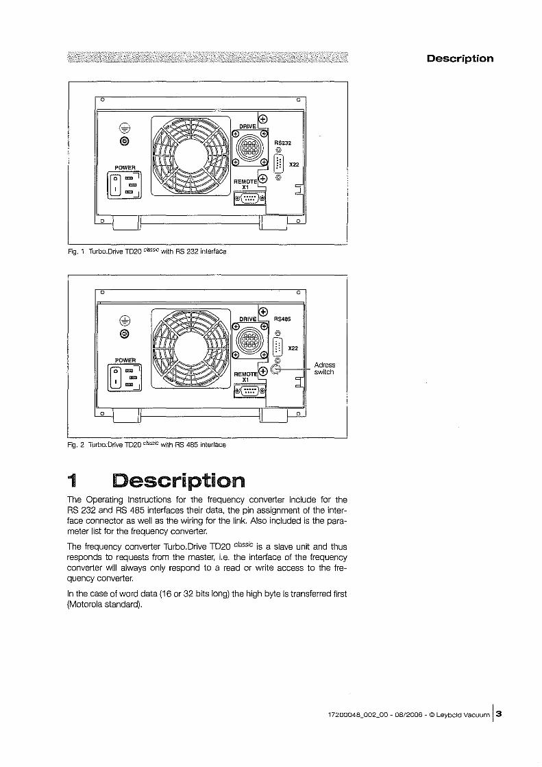
Fig. 1 Turbo.Drive TD20 classIc with RS 232 interface
a a
@ ~.~" @
~ ~~ ·~O X22
POWER ~~ :~ 8;] ~~ RE~?TE~- d I ""'-.J /IDs" ....
~ II II )-2-
Fig. 2 Turbo. Drive TD20 classic with AS 485 interface
1 Description
Adress switch
The Operating Instructions for the frequency converter include for the RS 232 and RS 485 interfaces their data, the pin assignment of the interface connector as well as the wiring for the link. Also included is the parameter list for the frequency converter.
The frequency converter TurboDrive TD20 classic is a slave unit and thus responds to requests from the master, i.e. the interface of the frequency converter will always only respond to a read or write access to the frequency converter.
In the case of word data (16 or 32 bits long) the high byte is transferred first (Motorola standard).
Description
17200048_002_00 - 08/2006 - © Leybold Vacuum 13
Description
1- - - r - - r - - T - - , - - -, - - -1- - - 1- - - r - - r--,..-...... Start-I I I I I I I I I even I Stop-
bit I 0 I 1 I 2 I 3 J 4 I 5 I 6 I 7 I parity I bit O-t--I--I - -...! - - _1- __ 1 ___ 1 ___ !... __ 1.. __ .! _ _ ..1 __ -;'_-1 __
Oata bits
Character frame 11 bit
l1li The even parity bit is a check bit; the number of "ones" of the data bits (including the parity bit) is an even number.
l1li Start bit ~ 0
III Stop bit ~ 1
Fig. 3 Structure of a data frame for transferring a string byte
Structure of the complete data string in accordance with USS protocol specification Byte NO. Abbre- Description Read access Write access Response from
viation to frequency to frequency the frequency
o
2
3-4
5 6
13-14
15-16
17-18
19-20
21-22
23
ADR
IND
data block in bytes 22
Frequency converter
and of access Reserved
Parameter index
Parameter value
Status and contro! bits
Recursive calculation: Checksum (I ~ 0) = byte (I = 0) Checksum (i) = checksum (i-1) XOR byte (i); i from 1 to 22, i = byte No.
4117200048_o02_o0 - 08/2006 - © Leybold Vacuum
converter converter converter
2
22
0 RS485: 0 ... 15
Value
0
0
0
0
0
0
0
Checksum (i=22)
'" co .,-en a: '0 c ro
'" '" '" en a:
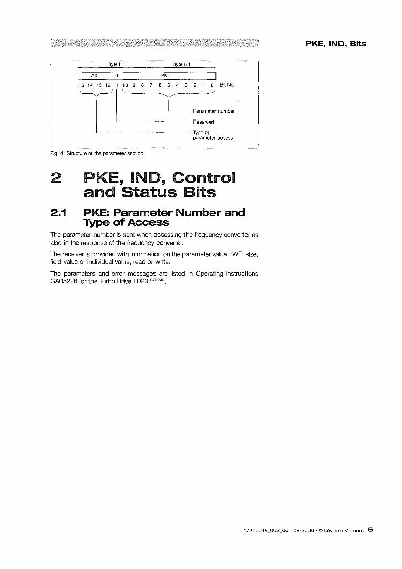
Byte i Byte i+ 1
AK o PN"
15 14 13 12 11 10 9 8 7 6 5 4 3 2 1 a Bit No.
L Parameter number ~II~' -~ Reserved
Type of parameter access
Fig. 4 Structure of the parameter section
2 PKE, INO, Control and Status Bits
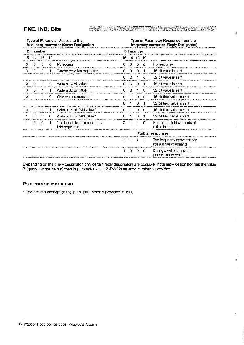
2.1 PKE: Parameter Number and Type of Access
The parameter number is sent when accessing the frequency converter as also in the response of the frequency converter.
The receiver is provided with information on the parameter value PWE: size, field value or individual value, read or write.
The parameters and error messages are listed in Operating Instructions GA05228 for the Turbo.Drive TD20 classic.
PKE, IND, Bits
17200048_002_00 - 08/2006 - © Leybold Vacuum [S
PKE, IND, Bits
Type of Parameter Access to the frequency converter (Query Designator)
If",,,dM~''"''',Y''~'~_'''~'V''''''''''W'''''''''''~f0'''0''''''_~'"""~,'p"""''0''"J,~,''''''''''''"z<'="",:"",v~,=,,,",'"'''-'''
Bit number
15 14 13 12
o 0 0 0 No access
o 0 0 Parameter value
o 0 o Write a 16 bit value
o 0 Write a 32 bit value
o o Field value
o Write a 16 bit field value'
o 0 0 Write a 32 bit field value'
o 0 Number of field elements of a field
Type of Parameter Response from the
~o~,~<"~<!~!:t~!!!:~,::~~~!'!~~l!,!~p!~E~=!~~!~~Looo< Bit number
15 14 13 12
o 0 0 0
000
o 0 o 000
o 0
o o o o o
o o 0
o o 0
o o
No
16 bit value is sent
32 bit value is sent
16 bit value is sent
32 bit value is sent
16 bit field value is sent
32 bit field value is sent
16 bit field value is sent
32 bit field value is sent
Number of field elements of a field is sent
Further responses
o
000
The frequency converter can not run the command
During a write access: no
Depending on the query designator, only certain reply designators are possible. If the reply designator has the value 7 (query cannot be run) then in parameter value 2 (PWE2) an error number is provided.
Parameter Index IND
• The desired element of the index parameter is provided in IND.
6]17200048_002_00 - 08/2006 ~ © Leybold Vacuum
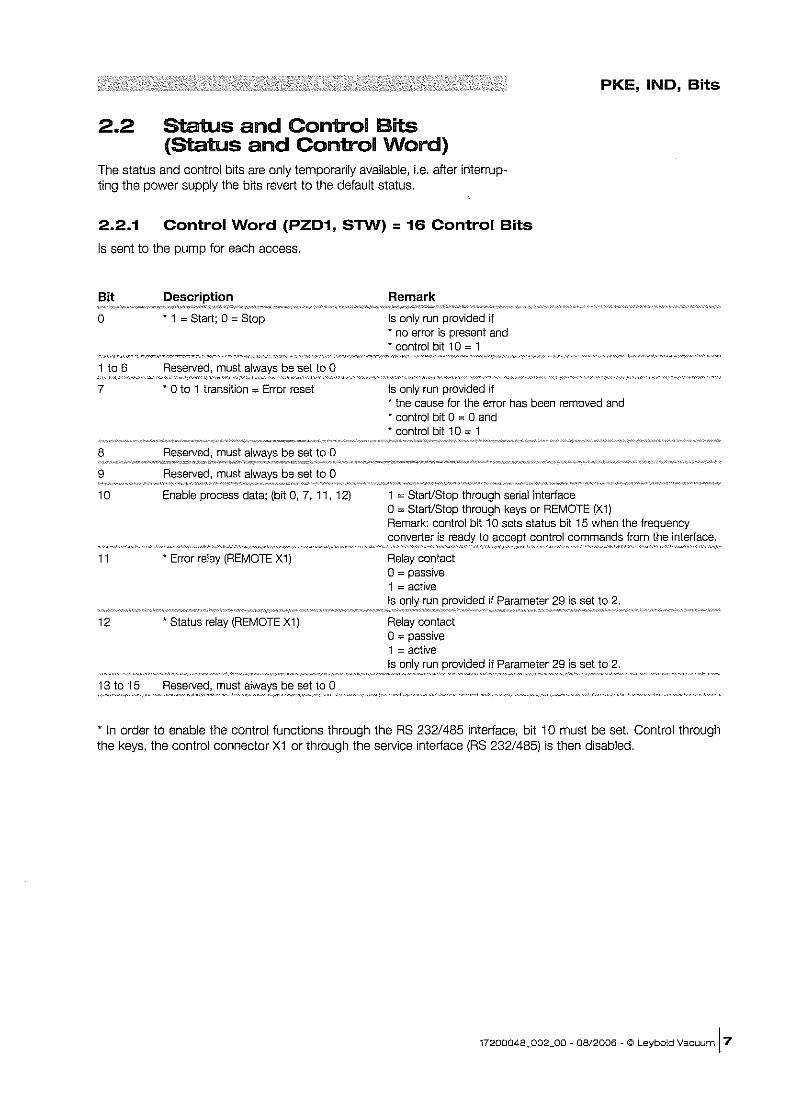
2.2 Status and Control Bits (Status and Control Word)
PKE, IND, Bits
The status and control bits are only temporarily available, i.e. after interrupting the power supply the bits revert to the default status.
2.2.1 Control Word (PZD1, SnN) = 16 Control Bits
Is sent to the pump for each access.
Bit
o • 1 = Start; 0 = Stop
1 to 6 Reserved, must be set to 0
7 ." 0 to 1 transition:;:; Error reset
8 Reserved, must be set to 0
9 Reserved, must be set to 0
10 Enable process data; (bit 0, 7, 11, 12)
11 • Error relay (REMOTE X1)
12 • Status relay (REMOTE X1)
13t015 Reserved, must be set to 0
Remark
Is only run provided if * no error is present and • control bit 10 = 1
Is only run provided if ." the cause for the error has been removed and • control bit 0 = 0 and • control bit 1 0 = 1
1 = StarVStop through serial interface o = StarVStop through keys or REMOTE (X1) Remark: control bit 10 sets status bit 15 when the frequency converter is to control commands from the interface.
Relay contact 0= passive 1 = active Is run
Relay contact 0= passive 1 = active Is run
if Parameter 29 is set to 2.
if Parameter 29 is set to 2.
• In order to enable the control functions through the RS 232/485 interface, bit 10 must be set. Control through the keys, the control connector X1 or through the service interface (RS 232/485) is then disabled.
17200048_002_00 - 08/2006 - © Leybold Vacuum [7
PKE, IND, Bits
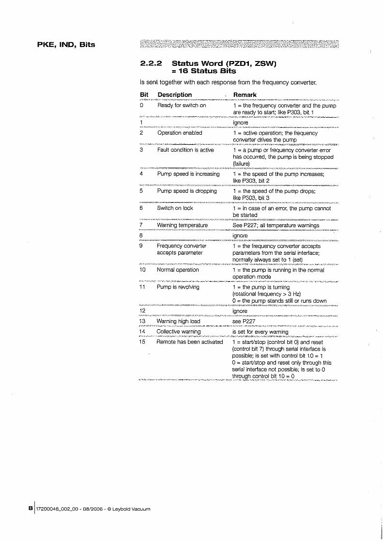
2.2.2 Status Word (PZD1, ZSW) = 16 Status Bits
Is sent together with each response from the frequency converter.
Bit Description
o Ready for switch on
2 Operation enabled
3 Fault condition is active
4 Pump speed is increasing
5 Pump speed is dropping
6 Switch on lock
Remark
1 = the frequency converter and the pump to like P303, bit 1
1 = active operation; the frequency converter drives the
1 = a pump or frequency converter error has occurred, the pump is being stopped
1 = the speed of the pump increases; like P303, bit 2
1 = the speed of the pump drops; like P303, bit 3
1 = in case of an error, the pump cannot be started ••.....• M·· •••• ~ ••.••.••• ~ •• ~ .••••••.•••.• ~.~.~~.~~.,.~. ~~
7 Warning temperature See P227; all temperature warnings ~n"",~'.,_"~~"<'"Ar."c,·~~~~·"',,o~_~,_c~"'c~.'~N_~~_·#"' __ ~"~. ,· .. ,=,,=-=-x====_ --==-=~="='.' .•. ~~'=""~O"-"_'.7"'A'=""'~"=""' __
8
9
10
11
12
13
14
Frequency converter accepts parameter
Normal operation
Pump is revolving
1 = the frequency converter accepts parameters from the serial interface;
set to 1
1 = the pump is running in the normal mode
1 = the pump is turning (rotational frequency> 3 Hz) o = the stands still or runs down
see P227
is set for
15 Remote has been activated 1 = starVstop (control bit 0) and reset (control bit 7) through serial interface is possible; is set with control bit 10 = 1 o = starVstop and reset only through this serial interface not possible; is set to 0
1 =
8117200048_o02_o0 - 08/2006 - © Leybold Vacuum
Notes
17200048_002_00 - 08/2006 - © Leybold Vacuum 19
Sales and Service Net Worldwide
Germany
Leybold Vacuum GmbH Bonner StrasS8 498 0-50968 Cologne Phone: +49·221-3471234 Fax: +49-221-3471245 [email protected]
Leybold Vacuum GmbH Sales Area North/East Branch office Berlin Buschkrugallee 33 1. Obergeschoss 0-12359 Berlin Phone: +49-30-435 609 a Fax: +49-30-435609 10 [email protected]
Leybold Vacuum GmbH Sales Area South/Southwest Branch office Munic Send linger Strasse 7 0-80331 Munic Phone: +49·99·357339-10 Fax: +49-89-357 33 9-33 [email protected] [email protected]
Leybold Vacuum GmbH Sales Area West Branch office Cologne Bonner Slrasse 498 0-50968 Cologne Phone: +49-221-3471270 Fax: +49-221-347129' [email protected]
Leybold Vacuum GmbH Service Center Emil-Hoffmann-Straf3e 43 0-50996 Cologne-Suerth Phone: +49-221-3471439 Fax: +49-221-3471945 [email protected]
Leybold Vacuum GmbH Mobile after sales service Emil-Hoffmann-StraBe 43 0-50996 Cologne-Suerth Phone: +49-221-3471765 Fax: +49-221-3471944 [email protected]
Leybold Vacuum GmbH, Dresden Zur Wetterwarte 50, Haus 304 D-01109 Dresden Service: Phone: +49-351-885500 Fax: +49-351-8855041 [email protected]
Europe
Belgium
Leybold Vacuum Nederland B.V. Belgisch bijkanloor Leuvensesteenweg 542-9A B-1930 Zaventem Sales: Phone: +32-2-7110083 Fax: +32-2-720 83 38 [email protected]
Service: Phone: +32·2-71100 82 Fax: +32-2-7208338 [email protected]
France
Leybold Vacuum France S.A 7, Avenue du Quebec ZA de Courtaboeuf 1 - B.P. 42 F-91942 Courtaboeuf Cedex Sales and Service: Phone; +33-1-69 82 48 00 Fax: +33-1-69 07 57 38 [email protected]
Leybold Vacuum France SA Valence Factory 640, Rue A. Berges - B.P 107 F-26501 Bourg-ies-Yalence Cedex Phone: +33-4-75823300 Fax: +33-4-75829269 marketing [email protected]
Great Britain
Leybold Vacuum UK Ltd. Unit 2 Silverglade Business Park Leatherhead Road UK-Chessington Surrey KT9 2QL
Sales: Phone: +44-13·72737300 Fax: +44-13-72737301 sales.uk@leybold,com
Service: Phone: +44-20·8971 7030 Fax: +44-20-8971 7003 [email protected]
Italy
Leybold Vacuum IlaUa S.p.A. 8, Via Trasimeno 1-20128 Milano Sales: Phone: +39-02-272231 Fax: +39-02-27209641 [email protected]
Service: Phone: +39-02-272231 Fax: +39-02-27223217 [email protected]
Leybold Vacuum Ilalia S.pA Reid Service Base Z.1. Le Capanne 1-05021 Acquasparta (TA) Phone: +39-0744-93 03 93 Fax: +39-0744-94 42 87 [email protected]
Hotline
Sales: -------------------,
+49-221-3471234 : Service: +49-221-3471765
, , , sales@leybold,com :
I [email protected] : L _________________________ ~
Leybold Vacuum USA Inc. 5700 Mellon Road Export, PA. 15632 Phone: 724-327-5700 Fax: 724-325-3577 info@leyboldvacuum,com
Netherlands
Leybold Vacuum Nederfand B.V. Computerweg 7 NL-3542 DP Utrecht Sales and Service: Phone: +31-346-583999 Fax: +31-346·583990 [email protected] [email protected]
Spain
Leybotd Vacuum Spain, SA C/. Huelva, 7 E-08940 Cornelia de Uobre9at (Barcelona)
Sales: Phone: +34-93-6664616 Fax: +34-93-6664370 [email protected] Service: Phone: +34-93-6664951 Fax: +34-93-685 40 10
Sweden
Leybold Vacuum Scandinavia AB Box 9084-SE-40D92 Goteborg Sales and Service: Phone: +46-31 -6884 70 Fax: +46-31-683939 [email protected] Visiting/delivery address: Datavagen 578 SE-43632 Askim
Switzerland
Leybold Vacuum $chweiz AG Leutschenbachstrasse 55 CH-8050 Zurich Sales: Phone: +41-044-3084050 Fax: +41-044-302 43 73 [email protected] Service: Phone: +41-044-308 40 62 Fax: +41-044-308 40 60
America
USA
Leybold Vacuum USA Inc. 5700 Mellon Road Export, PA 15632 Sales and Service: Phone: +1-724-327-5700 Fax: + 1-724-325-3577 [email protected]
Leybold Vacuum GmbH Bonner Strasse 498 0-50968 Cologne Phone: +49-221 347-0
Asia
P.R. China
Leybold Vacuum (fianjin) Intematlonal Trade Co., Ltd. Beichen Economic Development Area (BEDA), Shanghai Road Tianjin 300400 China
Sales and Service: Phone: +86-22-26970808 Fax: +86-22-26974061 Fax: +86-22-26972017 [email protected]
Leybold Vacuum (TIanjin) Equipment Manufacturing Co" Ltd. Beichen Economic Development Area (BEDA), Shanghai Aoad Tianjin 300400 China Sales and Service: Phone: +86-22-2697080a Fax: +86-22-26974061 Fax: +86-22-26972017 [email protected].
Leybold Vacuum (TIanjin)
Intemational Trade Co., Ltd. Shanghai Branch: Add: No. 33 76 Futedong San Ad. Waigaoqiao m Shanghai 200131 China Sales and Service: Phone: +86-21-5064-4666 Fax: +86·21·5064-4668 [email protected]
Leybold Vacuum (Tianjin) Guangzhou Branch: Add: G/F,#301 Building 110 Dongguangzhuang Rd. Tianhe District Guangzhou 510610 China Sales: Phone: +86·20-8723-7873 Phone: +86-20-8723-7597 Fax: +86-20-8723-7875 [email protected]
Leybold Vacuum (Tianjin) Intematlonal Trade Co., Ltd. Beijing Branch: 1-908, Beijing Landmark Towers 8 North Dongsanhuan Road Chaoyang District Beijing 100004 China Sales: Phone: +86·10·6590-7607 Fax: +86-10-6590-7622
India
Leybold Vacuum India Pvt Ltd. EL-22, J Block MIDC Bhosari Pune411026 India Sates: Phone: +91-20-3061 60000 Fax: +91-20-27121571 saies.india@leybold,com
Japan
Leybold Vacuum Japan Co., Ltd. Head Office Tabu AK Bldg. 4th Floor 23-3, Shin-Yokohama 3-chome Kohoku-ku, Yokohama·shi Kanagawa-ken 222-0033 Sales: Phone: +81-45-471-3330 Fax: +81-45-471-3323 [email protected]
Leybold Vacuum Japan Co., Ltd. Osaka Branch Office MARUTA Bldg. 7F 2-7-53, Nihi-Miyahara Yodogawa-ku Osaka-shi 532-0004 Sales: Phone: +81-6-6393·5211 Fax: +81-6-6393-5215 [email protected]
Leybold Vacuum Japan Co., Ltd. Tsukuba Technical S.C. Tsukuba Minami Daiichi Kogyo Danchi 21, Kasumi·no·Salo, Ami-machl, Inashikl-gun lbaraki-ken, 300-0315
Service: Phone: +81-29-889-2841 Fax: +81-29-889-2838 [email protected]
Korea
I-eybold Vacuum Korea Ltd. #761-4, Yulkeum-ri SungHwan-eup, Cheonan-City Choongchung·Namdo 330·807 Korea Sales: Phone: +82-41-580-4420 Fax: +82-41-588-3737 Service: Phone: +82-41-580-4415 Fax: +82-41-588-3737
Singapore
Leybold Vacuum Singapore Pte Ltd. No.1, International BUSiness Park, B1-208, The Synergy Singapore 609917 Sales and Service: Phone: +65-66652910 Fax: +65-6566 8202 [email protected]
Taiwan
Leybold Vacuum Taiwan Ltd. No 416-1, Sec. 3 Chung-Hsin Ad" Chu-Tung Hsin-Chu, Taiwan, R.O.C. Sales and Service: Phone: +886-3·5833 988 Fax: +886-3-5833 999 [email protected]
r-, b..Leybold
vacuum Fax: +49-221347-1250 [email protected] www.leybold.com