Embed Size (px)
Citation preview
User Manual for LEVIFLOW® LFIF-06 Flowmeters www.levitronix.com
PL-4511-00, RevA, DCO# RD First Release: 14-Jun-17 Last Update: 14-Jun-17
LEVIFLOW® INTEGRATED FLOWMETER LFIF
USER MANUAL
LEVIFLOW® Integrated Flowmeter: LFIF-06 (10 l/min)
This manual contains information necessary for the safe and proper use of the LEVIFLOW® LFS flowmeter series. Included are specifications for the standard configuration, components, and instructions regarding its use, installation, operation, adjustment, inspection and maintenance. For special configuration of the LEVIFLOW® flowmeters refer to accompanying information. If the flowmeters have to be configured for other parameter settings then the LEVIFLOW®
Configuration Software (see relevant manual Levitronix Doc.# PL-4501-00) is necessary. Please familiarize yourself with the contents of this manual to ensure the safe and effective use of this product. After reading, please store the manual where the personnel responsible for operating can readily refer to it at any time.
User Manual for LEVIFLOW® LFIF-06 Flowmeters www.levitronix.com
PL-4511-00, RevA, DCO# RD 2
Table of Contents
1 SAFETY PRECAUTIONS .......................................................................................................................................... 3
2 SPECIFICATIONS ..................................................................................................................................................... 4 2.1 Component Overview ........................................................................................................................................ 4 2.2 General Specifications ....................................................................................................................................... 4 2.3 Basic Dimensions of Main Components ............................................................................................................ 5
2.3.1 Dimensions of Flowmeter ................................................................................................................................................. 5 2.3.2 Dimensions of Cables ...................................................................................................................................................... 5
2.4 Overview of Parameter Configuration ................................................................................................................ 6
3 INSTALLATION ......................................................................................................................................................... 7 3.1 Electrical Installation .......................................................................................................................................... 7
3.1.1 Overview and Preparation ................................................................................................................................................ 7 3.1.2 Instructions for Electrical Installation ................................................................................................................................. 8 3.1.3 Configuration of Flowmeter Data ...................................................................................................................................... 9
3.2 Mechanical and Hydraulic Installation ................................................................................................................ 9 3.2.1 Instructions ....................................................................................................................................................................... 9
4 OPERATION ............................................................................................................................................................ 10 4.1 General Timing Specifications ......................................................................................................................... 10
4.1.1 Startup Time .................................................................................................................................................................. 10 4.1.2 Thermal Stability Time .................................................................................................................................................... 10 4.1.3 Zero Adjustment Activation Time .................................................................................................................................... 10 4.1.4 Automatic Zero Adjustment Duration .............................................................................................................................. 10
4.2 Operation ......................................................................................................................................................... 10 4.2.1 System Operation with PLC Interface ............................................................................................................................. 10 4.2.2 Operation with RS485 .................................................................................................................................................... 10 4.2.1 LED Messages ............................................................................................................................................................... 10 4.2.2 Operation with LEVIFLOW® Configuration Software ....................................................................................................... 11
5 INSPECTION AND MAINTENANCE ....................................................................................................................... 11
6 TROUBLESHOOTING ............................................................................................................................................. 12 6.1 Common Troubles ........................................................................................................................................... 12 6.2 Troubleshooting with LEVIFLOW® Configuration Software.............................................................................. 12
7 TECHNICAL SUPPORT .......................................................................................................................................... 12
8 APPENDIX ............................................................................................................................................................... 13 8.1 Regulatory Status ............................................................................................................................................ 13
8.1.1 CE Marking .................................................................................................................................................................... 13 8.2 Symbols and Signal Words .............................................................................................................................. 13
User Manual for LEVIFLOW® LFIF-06 Flowmeters www.levitronix.com
PL-4511-00, RevA, DCO# RD 3
1 Safety Precautions
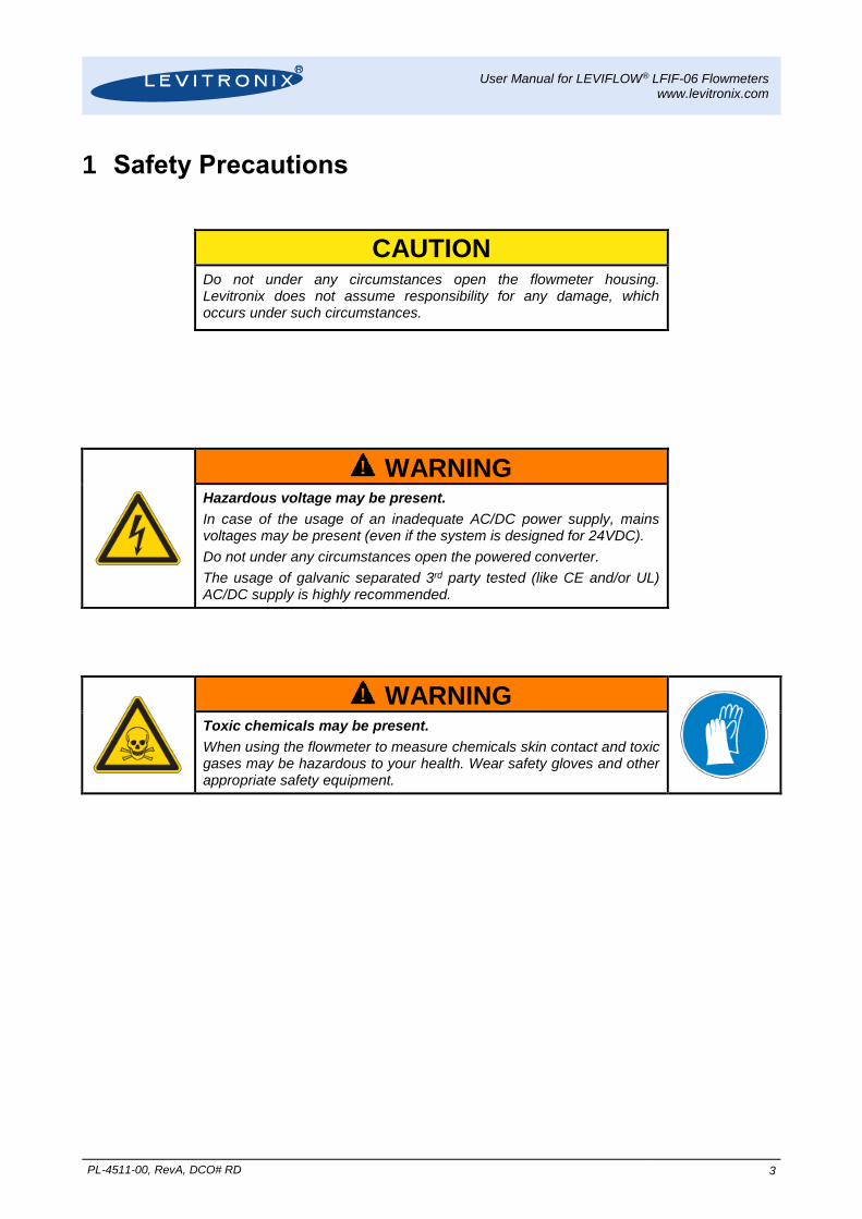
CAUTION Do not under any circumstances open the flowmeter housing.
Levitronix does not assume responsibility for any damage, which occurs under such circumstances.
! WARNING
Hazardous voltage may be present.
In case of the usage of an inadequate AC/DC power supply, mains voltages may be present (even if the system is designed for 24VDC).
Do not under any circumstances open the powered converter.
The usage of galvanic separated 3rd party tested (like CE and/or UL) AC/DC supply is highly recommended.
! WARNING
Toxic chemicals may be present.
When using the flowmeter to measure chemicals skin contact and toxic gases may be hazardous to your health. Wear safety gloves and other appropriate safety equipment.
User Manual for LEVIFLOW® LFIF-06 Flowmeters www.levitronix.com
PL-4511-00, RevA, DCO# RD 4
2 Specifications
2.1 Component Overview
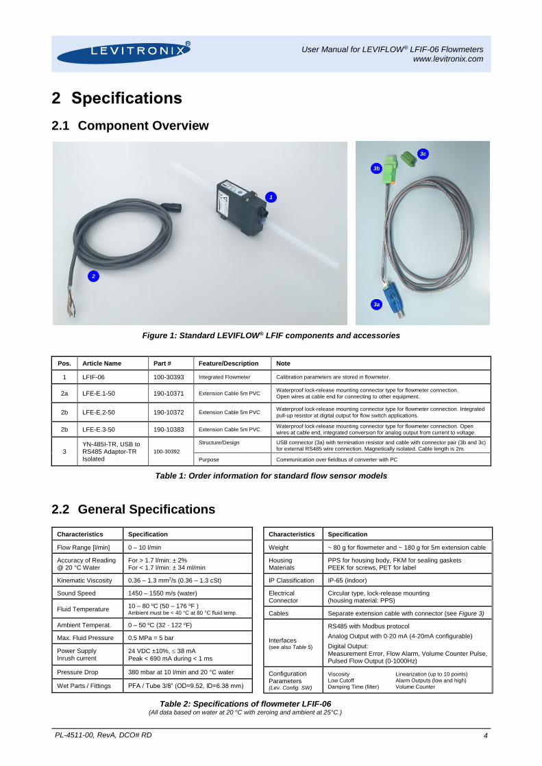
Figure 1: Standard LEVIFLOW® LFIF components and accessories
Pos. Article Name Part # Feature/Description Note
1 LFIF-06 100-30393 Integrated Flowmeter Calibration parameters are stored in flowmeter.
2a LFE-E.1-50 190-10371 Extension Cable 5m PVC Waterproof lock-release mounting connector type for flowmeter connection.
Open wires at cable end for connecting to other equipment.
2b LFE-E.2-50 190-10372 Extension Cable 5m PVC Waterproof lock-release mounting connector type for flowmeter connection. Integrated
pull-up resistor at digital output for flow switch applications.
2b LFE-E.3-50 190-10383 Extension Cable 5m PVC Waterproof lock-release mounting connector type for flowmeter connection. Open wires at cable end, integrated conversion for analog output from current to voltage.
3 YN-485I-TR, USB to RS485 Adaptor-TR Isolated
100-30392
Structure/Design USB connector (3a) with termination resistor and cable with connector pair (3b and 3c) for external RS485 wire connection. Magnetically isolated. Cable length is 2m.
Purpose Communication over fieldbus of converter with PC
Table 1: Order information for standard flow sensor models
2.2 General Specifications
Characteristics Specification
Flow Range [l/min] 0 – 10 l/min
Accuracy of Reading @ 20 °C Water
For > 1.7 l/min: ± 2% For < 1.7 l/min: ± 34 ml/min
Kinematic Viscosity 0.36 – 1.3 mm2/s (0.36 – 1.3 cSt)
Sound Speed 1450 – 1550 m/s (water)
Fluid Temperature 10 – 80 oC (50 – 176 oF ) Ambient must be < 40 °C at 80 °C fluid temp.
Ambient Temperat. 0 – 50 oC (32 - 122 oF)
Max. Fluid Pressure 0.5 MPa = 5 bar
Power Supply Inrush current
24 VDC ±10%, 38 mA
Peak < 690 mA during < 1 ms
Pressure Drop 380 mbar at 10 l/min and 20 °C water
Wet Parts / Fittings PFA / Tube 3/8” (OD=9.52, ID=6.38 mm)
Characteristics Specification
Weight ~ 80 g for flowmeter and ~ 180 g for 5m extension cable
Housing Materials
PPS for housing body, FKM for sealing gaskets PEEK for screws, PET for label
IP Classification IP-65 (indoor)
Electrical Connector
Circular type, lock-release mounting (housing material: PPS)
Cables Separate extension cable with connector (see Figure 3)
Interfaces (see also Table 5)
RS485 with Modbus protocol
Analog Output with 0-20 mA (4-20mA configurable)
Digital Output: Measurement Error, Flow Alarm, Volume Counter Pulse, Pulsed Flow Output (0-1000Hz)
Configuration Parameters (Lev. Config. SW)
Viscosity Linearization (up to 10 points) Low Cutoff Alarm Outputs (low and high) Damping Time (filter) Volume Counter
Table 2: Specifications of flowmeter LFIF-06 (All data based on water at 20 oC with zeroing and ambient at 25°C.)
1
2
3a
3b
3c
User Manual for LEVIFLOW® LFIF-06 Flowmeters www.levitronix.com
PL-4511-00, RevA, DCO# RD 5
2.3 Basic Dimensions of Main Components
2.3.1 Dimensions of Flowmeter
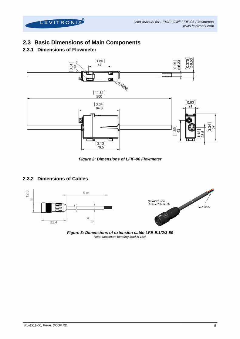
Figure 2: Dimensions of LFIF-06 Flowmeter
2.3.2 Dimensions of Cables
Figure 3: Dimensions of extension cable LFE-E.1/2/3-50 Note: Maximum bending load is 15N.
User Manual for LEVIFLOW® LFIF-06 Flowmeters www.levitronix.com
PL-4511-00, RevA, DCO# RD 6
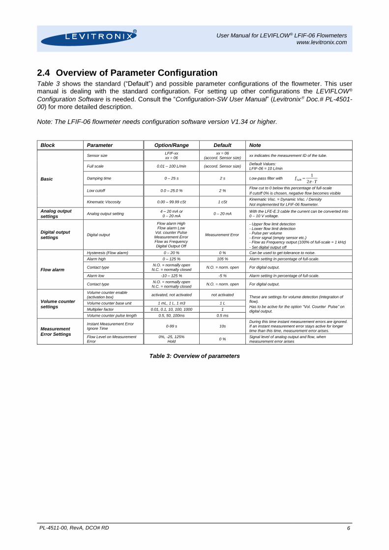
2.4 Overview of Parameter Configuration Table 3 shows the standard (“Default”) and possible parameter configurations of the flowmeter. This user manual is dealing with the standard configuration. For setting up other configurations the LEVIFLOW®
Configuration Software is needed. Consult the “Configuration-SW User Manual” (Levitronix Doc.# PL-4501-00) for more detailed description. Note: The LFIF-06 flowmeter needs configuration software version V1.34 or higher.
Block Parameter Option/Range Default Note
Basic
Sensor size LFIF-xx xx = 06
xx = 06 (accord. Sensor size)
xx indicates the measurement ID of the tube.
Full scale 0.01 – 100 L/min (accord. Sensor size) Default Values: LFIF-06 = 10 L/min
Damping time 0 – 25 s 2 s Low-pass filter with T
f dB
2
13
Low cutoff 0.0 – 25.0 % 2 % Flow cut to 0 below this percentage of full-scale
If cutoff 0% is chosen, negative flow becomes visible
Kinematic Viscosity 0.00 – 99.99 cSt 1 cSt Kinematic Visc. = Dynamic Visc. / Density
Not implemented for LFIF-06 flowmeter.
Analog output settings
Analog output setting 4 – 20 mA or
0 – 20 mA 0 – 20 mA
With the LFE-E.3 cable the current can be converted into 0 – 10 V voltage.
Digital output settings
Digital output
Flow alarm High Flow alarm Low
Vol. counter Pulse Measurement Error Flow as Frequency Digital Output Off
Measurement Error
- Upper flow limit detection
- Lower flow limit detection - Pulse per volume - Error signal (empty sensor etc.) - Flow as Frequency output (100% of full-scale = 1 kHz)
- Set digital output off
Flow alarm
Hysteresis (Flow alarm) 0 – 20 % 0 % Can be used to get tolerance to noise.
Alarm high 0 – 125 % 105 % Alarm setting In percentage of full-scale.
Contact type N.O. = normally open
N.C. = normally closed N.O. = norm. open For digital output.
Alarm low -10 – 125 % -5 % Alarm setting In percentage of full-scale.
Contact type N.O. = normally open
N.C. = normally closed N.O. = norm. open For digital output.
Volume counter settings
Volume counter enable (activation box)
activated, not activated not activated These are settings for volume detection (integration of flow).
Has to be active for the option “Vol. Counter Pulse” on digital output.
Volume counter base unit 1 mL, 1 L, 1 m3 1 L
Multiplier factor 0.01, 0.1, 10, 100, 1000 1
Volume counter pulse length 0.5, 50, 100ms 0.5 ms
Measurement Error Settings
Instant Measurement Error Ignore Time
0-99 s 10s During this time instant measurement errors are ignored. If an instant measurement error stays active for longer time than this time, measurement error arises.
Flow Level on Measurement Error
0%, -25, 125% Hold
0 % Signal level of analog output and flow, when measurement error arises
Table 3: Overview of parameters
User Manual for LEVIFLOW® LFIF-06 Flowmeters www.levitronix.com
PL-4511-00, RevA, DCO# RD 7
3 Installation
3.1 Electrical Installation
3.1.1 Overview and Preparation
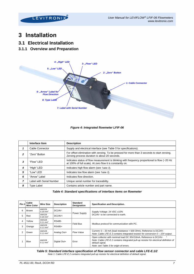
Figure 4: Integrated flowmeter LFIF-06
Interface Item Description
1 Cable Connector Supply and electrical interface (see Table 5 for specifications).
2 “Zero” Button For offset elimination with zeroing. To be pressed for more than 3 seconds to start zeroing. Zeroing process duration is about 20 seconds.
3 “Flow” LED Indicates status of flow measurement is blinking with frequency proportional to flow (~20 Hz at 100% of full scale). At zero flow it is constantly on.
4 “High” LED Indicates high flow alarm (see Table 3).
5 “Low” LED Indicates low flow alarm (see Table 3).
6 “Arrow” Label Indicates flow direction.
7 Label with Serial Number Unique serial number for traceability.
8 Type Label Contains article number and part name.
Table 4: Standard specifications of interface items on flowmeter
Pin # Cable Wire Color
Wire Size Description Standard Designation
Specification and Description.
6 Brown AWG26 0.18 mm2
DC24V- Power Supply
Supply Voltage: 24 VDC ±10%
DC24V- to be connected to earth. 5 Red
AWG26 0.18 mm2
DC24V+
4 Yellow AWG28 0.11 mm2
RS485- Field Bus Modbus protocol for communication with PC.
3 Orange AWG28 0.11 mm2
RS485+
2 Green AWG28 0.11 mm2
Analog Out+ Flow Value Current: 0 – 20 mA (load resistance < 500 Ohm), Reference is DC24V-
Note: Cable LFE-E.3 contains integrated resistor for conversion 0 – 10V output.
1 Blue AWG28 0.11 mm2
Digital Out+ Error
Open collector with nominal load DC 30V/10mA, Reference is DC24V- 1
Note: Cable LFE-E.2 contains integrated pull-up resistor for electrical definition of default signal.
Note: see Table 3 for origin of errors.
Table 5: Standard interface specification of flow sensor connector and cable LFE-E.1/2 Note 1: Cable LFE-E.2 contains integrated pull-up resistor for electrical definition of default signal.
2: „Zero“ Button
6: „Arrow“ Label for Flow Direction
1: Cable Connector
3: „Flow“ LED 4: „High“ LED
5: „Low“ LED
7: Label with Serial Number
8: Type Label
User Manual for LEVIFLOW® LFIF-06 Flowmeters www.levitronix.com
PL-4511-00, RevA, DCO# RD 8
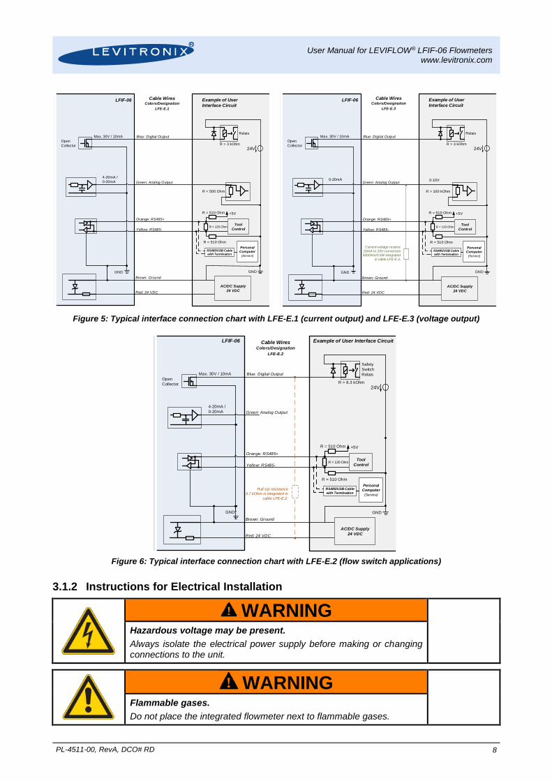
Figure 5: Typical interface connection chart with LFE-E.1 (current output) and LFE-E.3 (voltage output)
Figure 6: Typical interface connection chart with LFE-E.2 (flow switch applications)
3.1.2 Instructions for Electrical Installation
! WARNING
Hazardous voltage may be present.
Always isolate the electrical power supply before making or changing connections to the unit.
! WARNING
Flammable gases.
Do not place the integrated flowmeter next to flammable gases.
LFIF-06 Example of User
Interface Circuit
GND
Blue: Digital Output
Green: Analog Output
Orange: RS485+
Yellow: RS485-
GND
4-20mA /
0-20mA
RS485/USB Cablewith Termination
Personal
Computer
(Service)
24V
R < 500 Ohm
Max. 30V / 10mA
Open
Collector R > 3 kOhm
Relais
Cable WiresColors/Designation
LFE-E.1
R = 510 Ohm
Tool
Control
R = 510 Ohm
AC/DC Supply
24 VDCRed: 24 VDC
Brown: Ground
R = 120 Ohm
+5V
LFIF-06 Example of User
Interface Circuit
GND
Blue: Digital Output
Green: Analog Output
Orange: RS485+
Yellow: RS485-
GND
0-20mA
RS485/USB Cablewith Termination
Personal
Computer
(Service)
24V
R > 100 kOhm
Max. 30V / 10mA
Open
Collector R > 3 kOhm
Relais
Cable WiresColors/Designation
LFE-E.3
R = 510 Ohm
Tool
Control
R = 510 Ohm
AC/DC Supply
24 VDCRed: 24 VDC
Brown: Ground
R = 120 Ohm
+5V
Current-voltage resistor
20mA to 10V conversion
500Ohm/0.5W integrated
in cable LFE-E.3.
0-10V
LFIF-06 Example of User Interface Circuit
GND
Blue: Digital Output
Green: Analog Output
Orange: RS485+
Yellow: RS485-
GND
4-20mA /
0-20mA
RS485/USB Cablewith Termination
Personal
Computer
(Service)
24V
Max. 30V / 10mA
Open
Collector R > 8.3 kOhm
Safety
Switch
Relais
Cable WiresColors/Designation
LFE-E.2
R = 510 Ohm
Tool
Control
R = 510 Ohm
AC/DC Supply
24 VDCRed: 24 VDC
Brown: Ground
R = 120 Ohm
+5V
Pull-Up resistance
4.7 kOhm is integrated in
cable LFE-E.2.
User Manual for LEVIFLOW® LFIF-06 Flowmeters www.levitronix.com
PL-4511-00, RevA, DCO# RD 9
1. Remove the DC power from the flowmeter.
2. Remove the cable from the flowmeter connector.
3. Attach the necessary cable wires according to the pin specifications in Table 5.
4. For usage of a fuse at the power input (24 VDC) a 200 mA slow-blow type is recommended. Consider inrush current specification (see Table 2), when choosing the fuse type and the AC/DC power supply.
5. Attach the cable to the flowmeter connector.
6. Before powering on check again all wiring connections. Confirm that the terminals are securely fastened and that there is no possibility of short circuit.
3.1.3 Configuration of Flowmeter Data
The flowmeter comes configured with the sensor specific data already stored in it. A calibration sheet including the calibration data (the K-Factor and the 5 Calibration Values) is also part of the package. In case this data should have to be changed to the users specific needs LEVIFLOW® Configuration Software can be
used. Consult the configuration “Configuration-SW User Manual” (Levitronix Doc.# PL-4501-00) for handling with the LEVIFLOW® configuration software. Note: The LFIF-06 flowmeter needs configuration software version V1.34 or higher.
3.2 Mechanical and Hydraulic Installation
3.2.1 Instructions
1. In order to mechanically fix the sensor body 4 threads (see Figure 2) can be used.
2. Assure that at the mounting location the allowed ambient temperature is not exceeded (see Table 2)
3. The flow circuit should be completely filled with fluid. The converter DSP (Digital Signal Processor) contains special algorithms, which increase the robustness of the measurement against bubbles. However, assure that excessive bubbles are avoided in the circuit.
4. Ideal mounting position for the flow sensor is upward flow direction to avoid the stagnation of bubbles and particles in the measuring tube.
5. Make sure that the arrow mark on the flowmeter shows into the direction of the flow in the hydraulic circuit.
6. Avoid excessive vibrations such as in the neighborhood of displacement pumps. Insufficient contact of the transducer (within the sensor) onto the pipe wall caused by vibration may result in inaccurate measurement.
7. The flowmeter measures flow velocity. In order to obtain fully developed flow pattern for accurate velocity measurement, straight run of 60 mm upstream and of 40 mm downstream is recommended. If non-uniform turbulent flow or swirl flow is expected, install longer upstream straight run and/or a flow-rectifier.
8. To install on pipe that has open end, the sensor should be mounted in lower position of the pipe line.
9. The flowmeter should be mounted where pressure in the pipe is above the atmospheric pressure.
10. Devices like valves are recommended to be installed downstream of the sensor in order to prevent formation of bubbles in the liquid. An upstream valve may form bubbles reducing the intensity of the ultrasound signal and interfering with measurement.
11. A bypass pipe run (including bypass valve and shutoff valve) is recommended for easy zero adjustment and maintenance.
12. Please confirm that the maximum pressure is below the in Table 2 specified pressure of the sensor.
13. After setup a “Zeroing” is recommended. Assure that the sensor is completely filled with the according fluid and is free of bubbles. Stable liquid properties should be assured by flushing the circuit with the final liquid until temperature and viscosity becomes stable. After this zero flow shall be realized. Then push the “ZERO” button on the flowmeter for about 3 seconds. During adjustment the “High” and “LOW” LEDs are blinking.
14. In the following cases a re-zero is recommended:
a. 30 minutes after power-on of a cool converter and sensor
b. Change of fluid properties (temperature, viscosity, density)
c. Change of chemistry
d. Change of the hydraulic circuit
User Manual for LEVIFLOW® LFIF-06 Flowmeters www.levitronix.com
PL-4511-00, RevA, DCO# RD 10
4 Operation
4.1 General Timing Specifications
4.1.1 Startup Time
After power-on a startup sequence proceeded. During this sequence flow measurement is not performed. Start-up time is about 3 seconds.
4.1.2 Thermal Stability Time
To guarantee specified accuracy thermal stability of sensor has to be reached. Therefore it is recommended to wait 30 minutes after power-on.
4.1.3 Zero Adjustment Activation Time
There are two possibilities to activate zero adjustment:
1. Activating by LEVIFLOW® configuration software: Zero adjustment starts immediately after pressing corresponding button.
2. Activating by “Zero” button on the flowmeter (see Figure 4) has to be pressed during more than 3 seconds to initiate zero adjustment.
4.1.4 Automatic Zero Adjustment Duration The duration to perform an automatic zero adjustment is about 20 seconds.
4.2 Operation
4.2.1 System Operation with PLC Interface
Figure 5 shows the standard configuration of the digital and analogue output. For other configurations the
LEVIFLOW® configuration software has to be used (according manual is Levitronix Doc.# PL-4501-00).
Note: The LFIF-06 flowmeter needs configuration software version V1.34 or higher.
4.2.2 Operation with RS485
Operation with communication over an RS485 bus is possible. The according MODBUS protocol can be
requested at Levitronix.
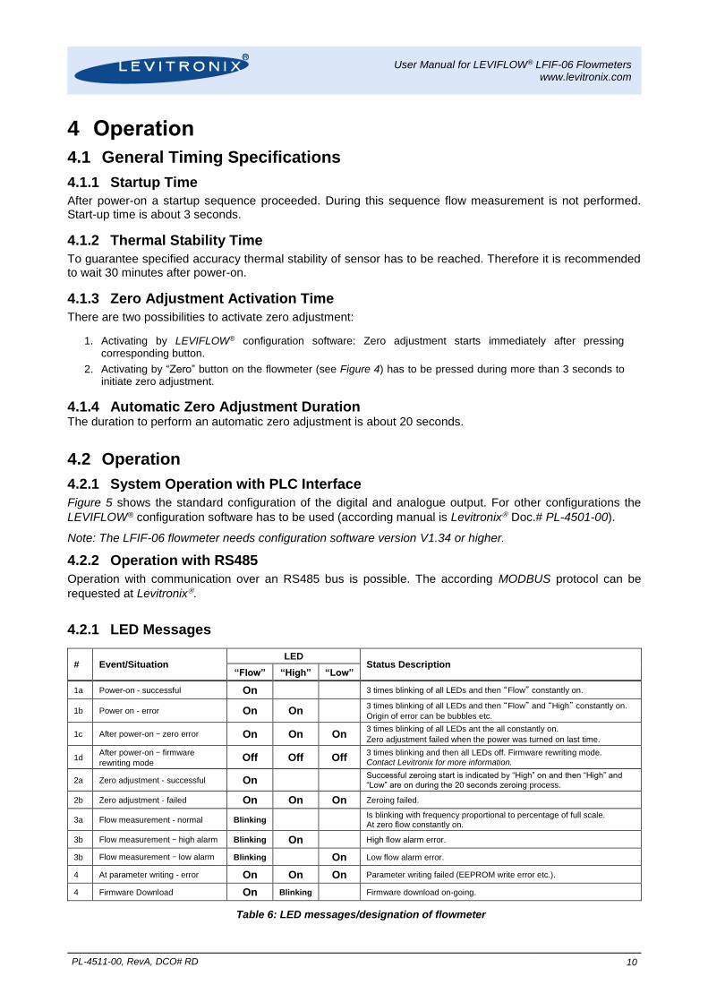
4.2.1 LED Messages
# Event/Situation LED
Status Description “Flow” “High” “Low”
1a Power-on - successful On 3 times blinking of all LEDs and then “Flow” constantly on.
1b Power on - error On On 3 times blinking of all LEDs and then “Flow” and “High” constantly on.
Origin of error can be bubbles etc.
1c After power-on – zero error On On On 3 times blinking of all LEDs ant the all constantly on.
Zero adjustment failed when the power was turned on last time.
1d After power-on – firmware
rewriting mode Off Off Off
3 times blinking and then all LEDs off. Firmware rewriting mode. Contact Levitronix for more information.
2a Zero adjustment - successful On Successful zeroing start is indicated by “High” on and then “High” and “Low” are on during the 20 seconds zeroing process.
2b Zero adjustment - failed On On On Zeroing failed.
3a Flow measurement - normal Blinking Is blinking with frequency proportional to percentage of full scale. At zero flow constantly on.
3b Flow measurement – high alarm Blinking On High flow alarm error.
3b Flow measurement – low alarm Blinking On Low flow alarm error.
4 At parameter writing - error On On On Parameter writing failed (EEPROM write error etc.).
4 Firmware Download On Blinking Firmware download on-going.
Table 6: LED messages/designation of flowmeter
User Manual for LEVIFLOW® LFIF-06 Flowmeters www.levitronix.com
PL-4511-00, RevA, DCO# RD 11
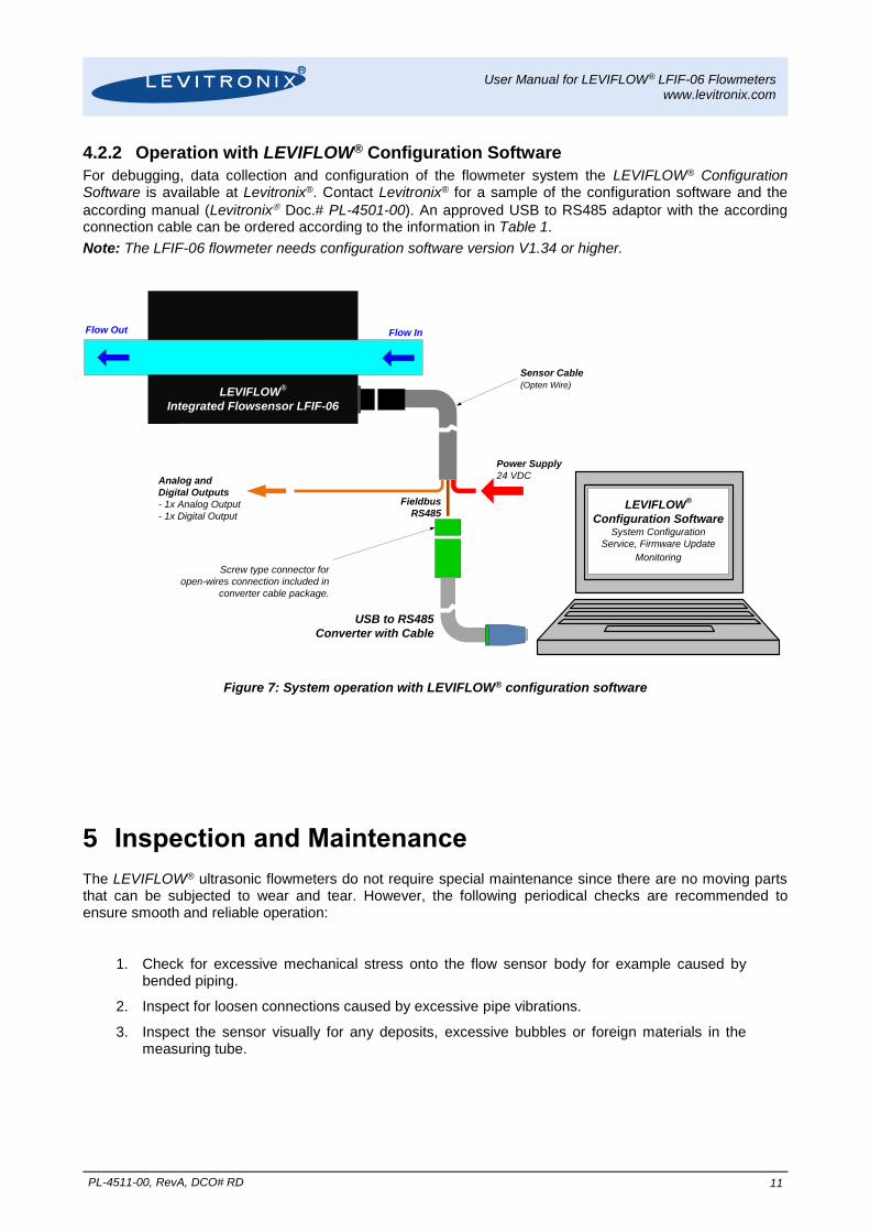
4.2.2 Operation with LEVIFLOW® Configuration Software
For debugging, data collection and configuration of the flowmeter system the LEVIFLOW® Configuration Software is available at Levitronix®. Contact Levitronix® for a sample of the configuration software and the
according manual (Levitronix Doc.# PL-4501-00). An approved USB to RS485 adaptor with the according connection cable can be ordered according to the information in Table 1.
Note: The LFIF-06 flowmeter needs configuration software version V1.34 or higher.
Figure 7: System operation with LEVIFLOW® configuration software
5 Inspection and Maintenance
The LEVIFLOW® ultrasonic flowmeters do not require special maintenance since there are no moving parts that can be subjected to wear and tear. However, the following periodical checks are recommended to ensure smooth and reliable operation:
1. Check for excessive mechanical stress onto the flow sensor body for example caused by bended piping.
2. Inspect for loosen connections caused by excessive pipe vibrations.
3. Inspect the sensor visually for any deposits, excessive bubbles or foreign materials in the measuring tube.
Power Supply
24 VDCAnalog and
Digital Outputs
- 1x Analog Output
- 1x Digital OutputLEVIFLOW
®
Configuration SoftwareSystem Configuration
Service, Firmware Update
Monitoring
Flow InFlow Out
LEVIFLOW®
Integrated Flowsensor LFIF-06
Sensor Cable
(Opten Wire)
Screw type connector for
open-wires connection included in
converter cable package.
USB to RS485
Converter with Cable
Fieldbus
RS485
User Manual for LEVIFLOW® LFIF-06 Flowmeters www.levitronix.com
PL-4511-00, RevA, DCO# RD 12
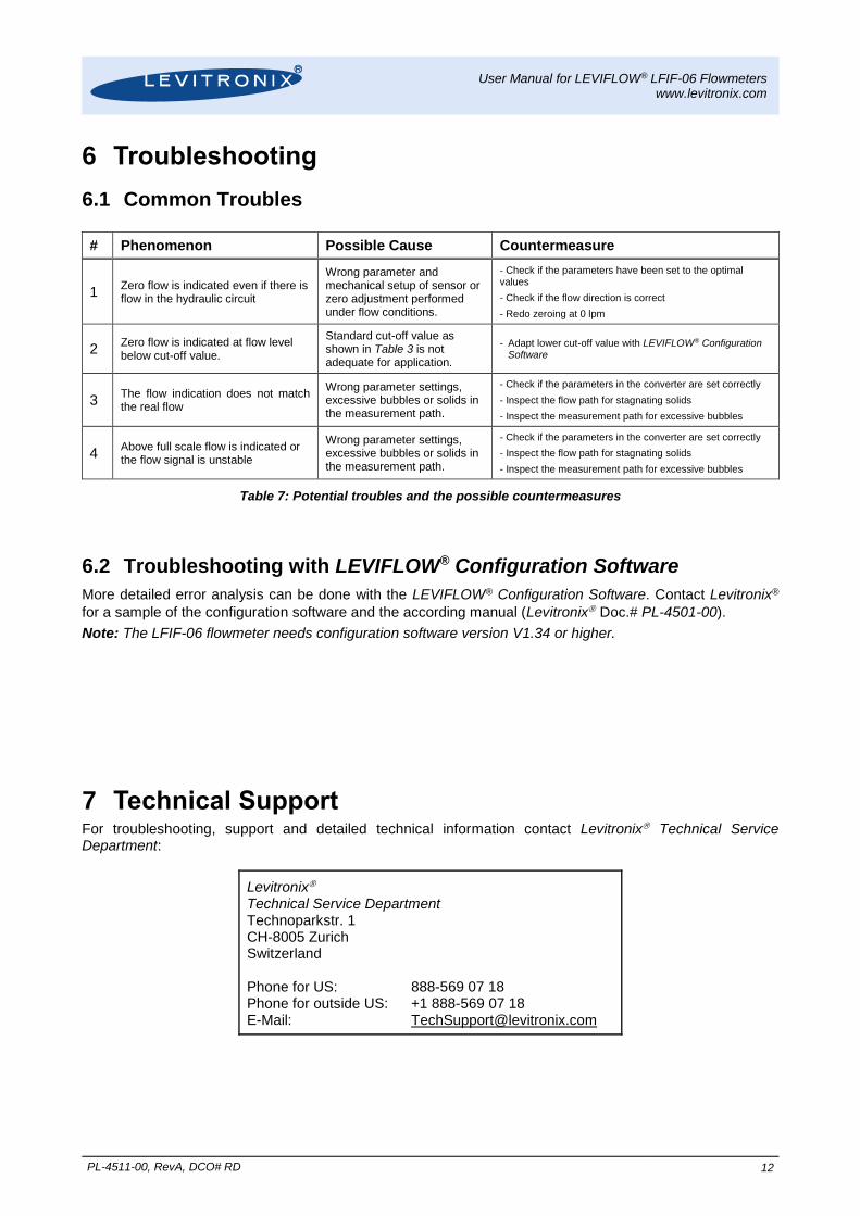
6 Troubleshooting
6.1 Common Troubles
# Phenomenon Possible Cause Countermeasure
1 Zero flow is indicated even if there is flow in the hydraulic circuit
Wrong parameter and mechanical setup of sensor or zero adjustment performed under flow conditions.
- Check if the parameters have been set to the optimal values
- Check if the flow direction is correct
- Redo zeroing at 0 lpm
2 Zero flow is indicated at flow level below cut-off value.
Standard cut-off value as shown in Table 3 is not adequate for application.
- Adapt lower cut-off value with LEVIFLOW® Configuration Software
3 The flow indication does not match the real flow
Wrong parameter settings, excessive bubbles or solids in the measurement path.
- Check if the parameters in the converter are set correctly
- Inspect the flow path for stagnating solids
- Inspect the measurement path for excessive bubbles
4 Above full scale flow is indicated or the flow signal is unstable
Wrong parameter settings, excessive bubbles or solids in the measurement path.
- Check if the parameters in the converter are set correctly
- Inspect the flow path for stagnating solids
- Inspect the measurement path for excessive bubbles
Table 7: Potential troubles and the possible countermeasures
6.2 Troubleshooting with LEVIFLOW® Configuration Software
More detailed error analysis can be done with the LEVIFLOW® Configuration Software. Contact Levitronix®
for a sample of the configuration software and the according manual (Levitronix Doc.# PL-4501-00).
Note: The LFIF-06 flowmeter needs configuration software version V1.34 or higher.
7 Technical Support For troubleshooting, support and detailed technical information contact Levitronix Technical Service Department:
Levitronix Technical Service Department Technoparkstr. 1 CH-8005 Zurich Switzerland Phone for US: 888-569 07 18 Phone for outside US: +1 888-569 07 18 E-Mail: [email protected]
User Manual for LEVIFLOW® LFIF-06 Flowmeters www.levitronix.com
PL-4511-00, RevA, DCO# RD 13
8 Appendix
8.1 Regulatory Status
8.1.1 CE Marking
The LEVIFLOW® LFIF-06 flowmeter, in its various configurations is in conformity with the below mentioned European Directives. The flowmeter is thought to be used in hydraulic circuits of the production equipment of Semiconductor and Chemical industry. EMC Directive 2014/30/EC:
The following particular harmonized standards of the EMC Directive are tested and confirmed.
EN 61000-6-4 Generic Emission standard for industrial environments
EN 61000-6-2 Generic Immunity standard for industrial environments
Pressure Equipment Directive 97/23/EC:
The pressure equipment directive is used as guide line according to Category I Modul A (internal quality control). For maximum pressure validation the following standard is followed:
EN ISO 15494 Plastic piping system for industrial applications
ISO12100 Safety for machinery – principles for risk assessments: used for system risk analysis.
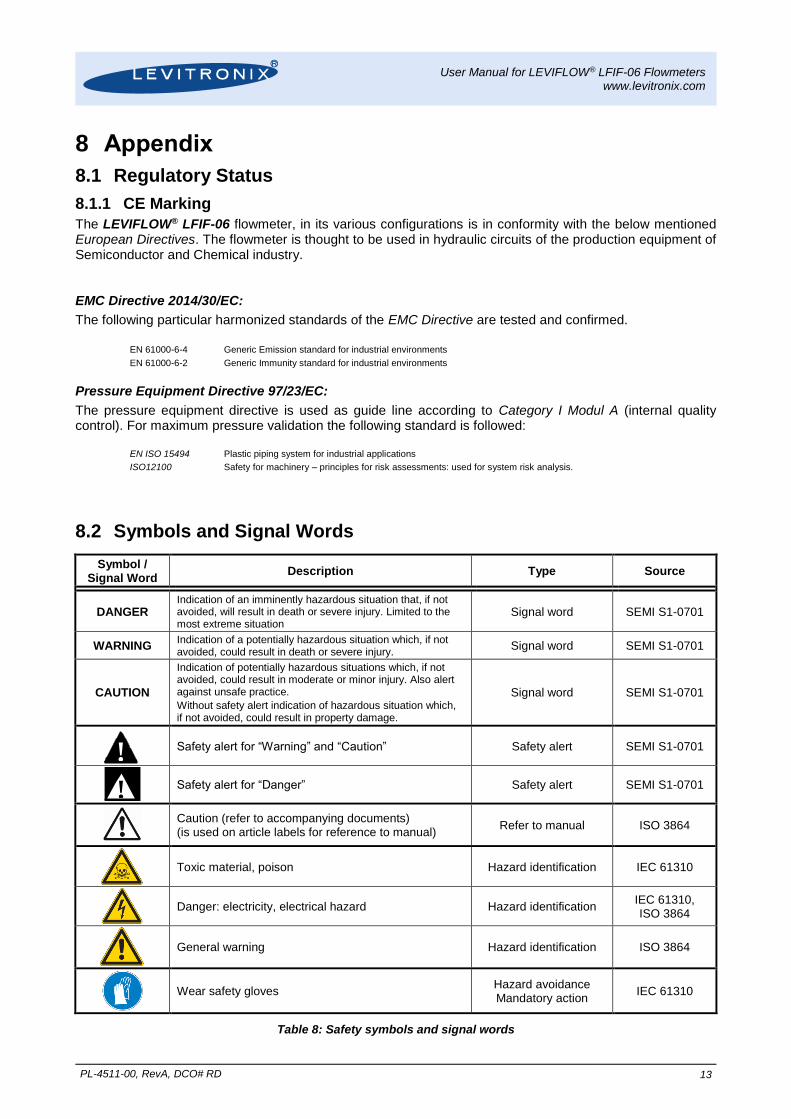
8.2 Symbols and Signal Words
Symbol / Signal Word
Description Type Source
DANGER Indication of an imminently hazardous situation that, if not avoided, will result in death or severe injury. Limited to the most extreme situation
Signal word SEMI S1-0701
WARNING Indication of a potentially hazardous situation which, if not avoided, could result in death or severe injury.
Signal word SEMI S1-0701
CAUTION
Indication of potentially hazardous situations which, if not avoided, could result in moderate or minor injury. Also alert against unsafe practice.
Without safety alert indication of hazardous situation which, if not avoided, could result in property damage.
Signal word SEMI S1-0701
!
Safety alert for “Warning” and “Caution” Safety alert SEMI S1-0701
! Safety alert for “Danger” Safety alert SEMI S1-0701
Caution (refer to accompanying documents) (is used on article labels for reference to manual)
Refer to manual ISO 3864
Toxic material, poison Hazard identification IEC 61310
Danger: electricity, electrical hazard Hazard identification IEC 61310, ISO 3864
General warning Hazard identification ISO 3864
Wear safety gloves Hazard avoidance Mandatory action
IEC 61310
Table 8: Safety symbols and signal words


![User's AXF Manual Magnetic Flowmeter Integral Flowmeter ... · Magnetic Flowmeter Integral Flowmeter/ Remote Flowtube [Hardware Edition] IM 01E20D01-01E IM 01E20D01-01E 7th Edition](https://img.pdfslide.us/doc/110x75/5e9c29fa54300501b21ae83a/users-axf-manual-magnetic-flowmeter-integral-flowmeter-magnetic-flowmeter-integral.jpg)