Embed Size (px)
Citation preview

Lessons from Braidwood with Lessons from Braidwood with Relevance to Daya BayRelevance to Daya Bay
Jonathan LinkJonathan Link
Virginia Polytechnic InstituteVirginia Polytechnic Institute
Workshop on Future PRC-U.S. Cooperation in Workshop on Future PRC-U.S. Cooperation in High Energy PhysicsHigh Energy Physics
June 12, 2006June 12, 2006
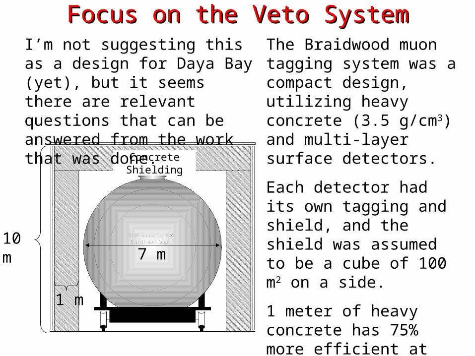
Focus on the Veto SystemFocus on the Veto System
Concrete Shielding
1 m
10 m7 m
The Braidwood muon tagging system was a compact design, utilizing heavy concrete (3.5 g/cm3) and multi-layer surface detectors.
Each detector had its own tagging and shield, and the shield was assumed to be a cube of 100 m2 on a side.
1 meter of heavy concrete has 75% more efficient at slowing GeV neutrons than 2 meter of water. MeV neutrons are mitigated by the hydrogen rich buffer.
I’m not suggesting this as a design for Daya Bay (yet), but it seems there are relevant questions that can be answered from the work that was done.
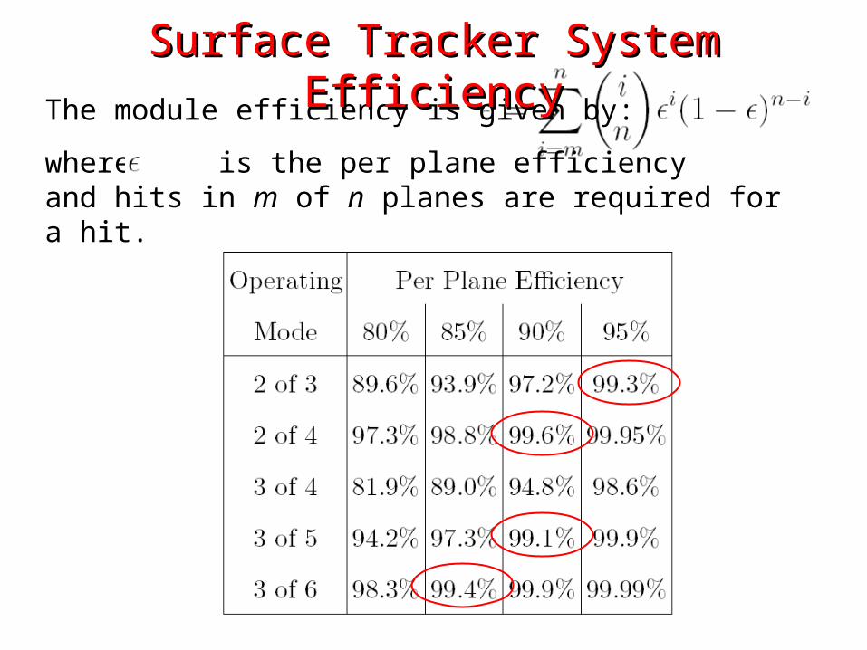
The module efficiency is given by:
where is the per plane efficiencyand hits in m of n planes are required for a hit.
Surface Tracker System EfficiencySurface Tracker System Efficiency

Random Firing Rate and Dead TimeRandom Firing Rate and Dead Time
The system random firing rate is given by:
where R is the per plane rate (0.05 Hz/cm2 for Belle RPCs) A is the coincidence area (2.4 m2 for 1.55 m×1.55 m module) and Δt is the coincidence time window (100 ns)
Rsys=0.87 Hz/module (2 of 3)
The dead time due to tagging random firing is:
Which results in tolerable dead times for all configurations, with reasonable assumptions.
Operating Mode Dead Time (%)
2 of 3 1.1
2 of 4 2.1
3 of 4 1.7×10⁻⁴
3 of 5 4.2×10⁻⁴
3 of 6 8.5×10⁻⁴
Conclusions on Surface SystemsConclusions on Surface SystemsFor a per plane efficiency of > 95%, an operating more of 2 out of 3 results in >99% system efficiency. Belle RPC efficiency is reported as 95% and the inefficiencies are largely associated with edges and spacers.
Requiring 2 hits out of 4 layer works down to 90% per plane efficiency.
Both configurations have tolerable dead times from random firing assuming the Belle RPC firing rate (which has a significant contribution from cosmics).
In a multi-layer surface system the per plane efficiencies can easily be measured allowing you to determine a precise, position dependant system efficiency.
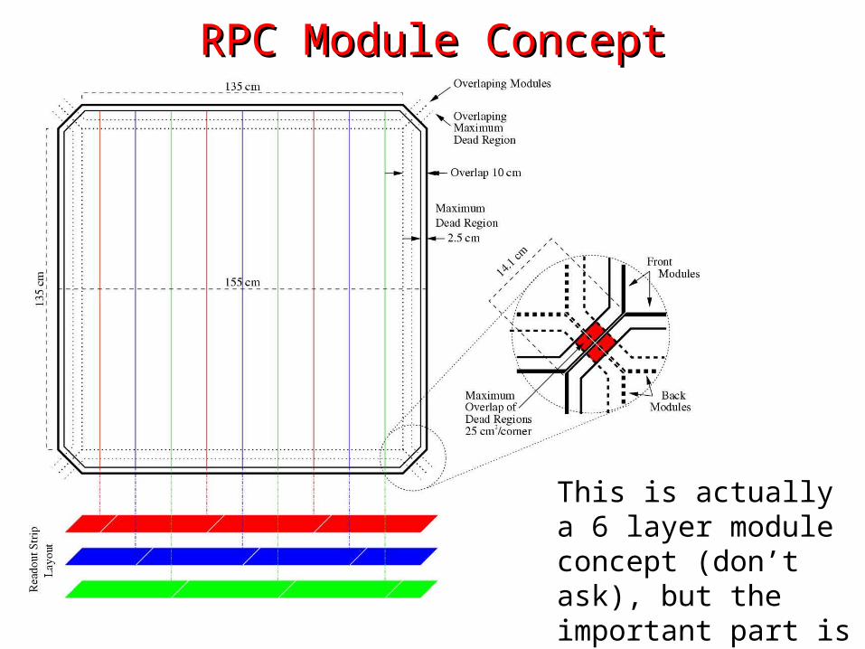
RPC Module ConceptRPC Module Concept
This is actually a 6 layer module concept (don’t ask), but the important part is the overlap design.
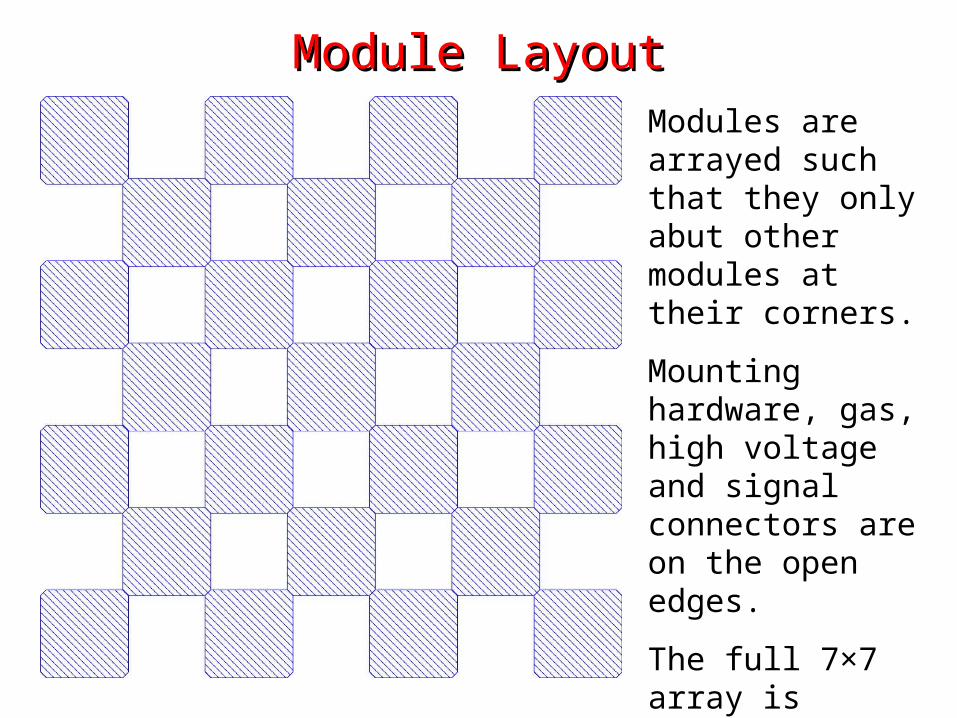
Module LayoutModule LayoutModules are arrayed such that they only abut other modules at their corners.
Mounting hardware, gas, high voltage and signal connectors are on the open edges.
The full 7×7 array is completed with a complimentary second layer which overlaps the modules of the first layer.

Module LayoutModule LayoutModules are arrayed such that they only abut other modules at their corners.
Mounting hardware, gas, high voltage and signal connectors are on the open edges.
The full 7×7 array is completed with a complimentary second layer which overlaps the modules of the first layer.
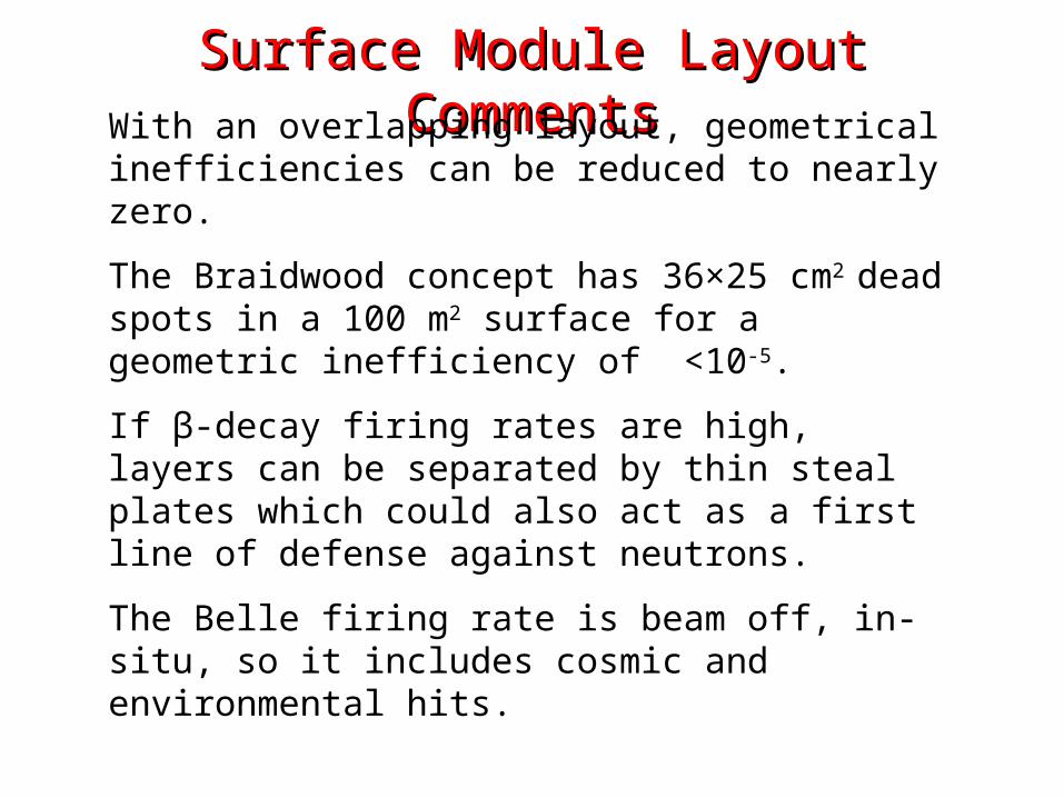
Surface Module Layout CommentsSurface Module Layout CommentsWith an overlapping layout, geometrical inefficiencies can be reduced to nearly zero.
The Braidwood concept has 36×25 cm2 dead spots in a 100 m2 surface for a geometric inefficiency of <10-5.
If β-decay firing rates are high, layers can be separated by thin steal plates which could also act as a first line of defense against neutrons.
The Belle firing rate is beam off, in-situ, so it includes cosmic and environmental hits.

Concrete Shielding
Possible Design for Daya BayPossible Design for Daya Bay
Dense plastic or some other low background material
If radioactive background from external materials are a major problem in the central detector then consider this possibility…
1. The outer shield is constructed of low background structural concrete (it must be possible to get concrete that is significantly cleaner than Daya Bay granite.
2. Inner layer of a dense, very low background, and preferably solid (self supporting?) material.
3. Tank steal and buffer volume also provide gamma attenuation.

ConclusionsConclusions• The Braidwood tagging and shield system design is compact and highly efficient.
• The formulas for calculating efficiency and dead time depend only on the hit definition, per plane efficiency, and plane firing rate. These calculation can be applied directly to the Daya Bay muon tracker.
• Actual efficiencies and dead times have be calculated for a range of operating modes, which indicate that as few as three layers could have satisfactory efficiencies and dead time rates.
• A concept for a geometrically efficient array of RPCs was shown. This concept should be applicable to other detector technologies such as plastic scintillator.
• A concept for a completely dry Daya Bay veto was shown. This system likely has advantages in cost, engineering and complexity, but work is needed to understand radioactive backgrounds.