Embed Size (px)
Citation preview
IFP Energies nouvelles International ConferenceRencontres Scientifiques d'IFP Energies nouvelles
LES4ICE’16: LES for Internal Combustion Engine Flows Conference
LES of n-Dodecane Spray Combustion Using a Multiple
Representative Interactive Flamelets Model
Marco Davidovic1*, Tobias Falkenstein
1*, Mathis Bode
1, Liming Cai
1, Seongwon Kang
2,
Jörn Hinrichs1and Heinz Pitsch
1
1 Institute for Combustion Technology, RWTH University, 52056 Aachen - Germany2 Department of Mechanical Engineering, Sogang University, Mapo, Seoul 121-742 - Korea
e-mail: [email protected] - [email protected] - [email protected] - [email protected] [email protected] - [email protected] - [email protected]
* Corresponding authors
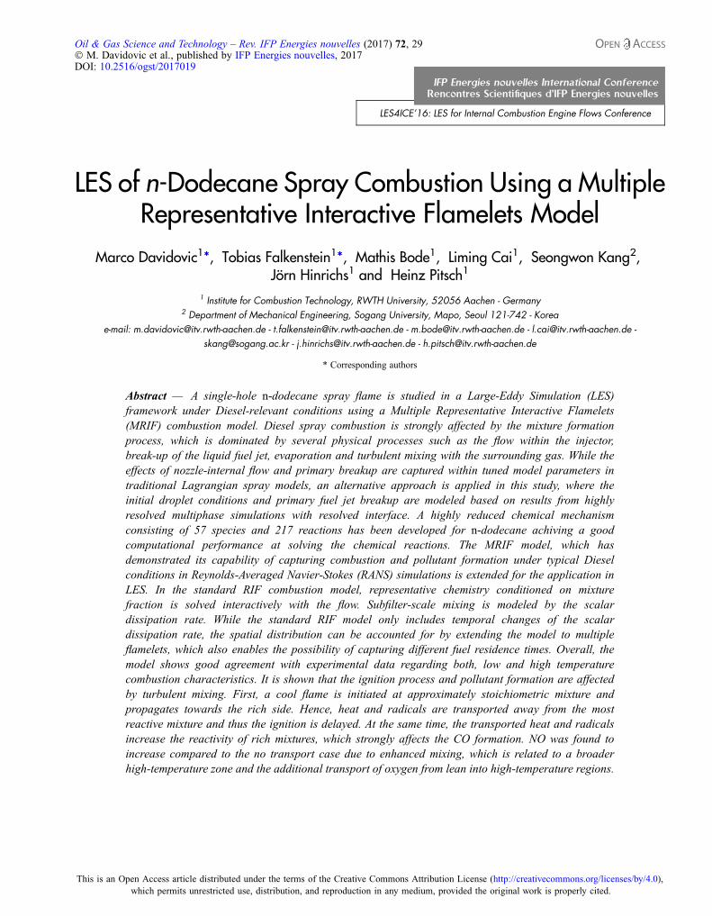
Abstract — A single-hole n-dodecane spray flame is studied in a Large-Eddy Simulation (LES)framework under Diesel-relevant conditions using a Multiple Representative Interactive Flamelets(MRIF) combustion model. Diesel spray combustion is strongly affected by the mixture formationprocess, which is dominated by several physical processes such as the flow within the injector,break-up of the liquid fuel jet, evaporation and turbulent mixing with the surrounding gas. While theeffects of nozzle-internal flow and primary breakup are captured within tuned model parameters intraditional Lagrangian spray models, an alternative approach is applied in this study, where theinitial droplet conditions and primary fuel jet breakup are modeled based on results from highlyresolved multiphase simulations with resolved interface. A highly reduced chemical mechanismconsisting of 57 species and 217 reactions has been developed for n-dodecane achiving a goodcomputational performance at solving the chemical reactions. The MRIF model, which hasdemonstrated its capability of capturing combustion and pollutant formation under typical Dieselconditions in Reynolds-Averaged Navier-Stokes (RANS) simulations is extended for the application inLES. In the standard RIF combustion model, representative chemistry conditioned on mixturefraction is solved interactively with the flow. Subfilter-scale mixing is modeled by the scalardissipation rate. While the standard RIF model only includes temporal changes of the scalardissipation rate, the spatial distribution can be accounted for by extending the model to multipleflamelets, which also enables the possibility of capturing different fuel residence times. Overall, themodel shows good agreement with experimental data regarding both, low and high temperaturecombustion characteristics. It is shown that the ignition process and pollutant formation are affectedby turbulent mixing. First, a cool flame is initiated at approximately stoichiometric mixture andpropagates towards the rich side. Hence, heat and radicals are transported away from the mostreactive mixture and thus the ignition is delayed. At the same time, the transported heat and radicalsincrease the reactivity of rich mixtures, which strongly affects the CO formation. NO was found toincrease compared to the no transport case due to enhanced mixing, which is related to a broaderhigh-temperature zone and the additional transport of oxygen from lean into high-temperature regions.
Oil & Gas Science and Technology – Rev. IFP Energies nouvelles (2017) 72, 29� M. Davidovic et al., published by IFP Energies nouvelles, 2017DOI: 10.2516/ogst/2017019
This is an Open Access article distributed under the terms of the Creative Commons Attribution License (http://creativecommons.org/licenses/by/4.0),which permits unrestricted use, distribution, and reproduction in any medium, provided the original work is properly cited.
INTRODUCTION
A large fraction of today’s energy consumption is attributa-ble to the transportation sector, which is expected to growfurther in the foreseeable future. While substantial effort isbeing directed towards electrified propulsion systems, inter-nal combustion engines are expected to provide the majorityof this transportation energy demand [1]. Therefore, furtherdevelopment of internal combustion engines has a hugepotential to reduce environmental impact through emissionreduction. However, the engine combustion process is notfully understood and thus truly predictive models do notyet exist. The Engine Combustion Network (ECN) [2] isan international collaboration of research groups that aimsto advance the scientific understanding of combustion atengine relevant conditions. In particular, the combustionprocess of a single-hole Diesel injector using n-dodecane,denoted as “Spray A”, has been a principal focus. In the pre-sent work, the Spray A target case, which is defined as a1,500 bar single injection at 900 K gas temperature and60 bar back-pressure is studied. Even though significant pro-gress has been made in experimental methods, only limitedinformation of the in-cylinder combustion process can beextracted. Computational tools can provide additionalinsight in order to exploit the full potential of internal com-bustion engines regarding emission reduction and efficiencygain. Large-Eddy Simulations (LES) solve a filtered flowfield and thus resolve the large scale turbulent fluctuations.Hence, LES describe the mixing fields more accurately com-pared to the classical Reynolds-Averaged Navier-Stokes(RANS) approach. Additionally, intrinsic cycle-to-cyclevariations can be captured in LES, while RANS is a deter-ministic method by definition and thus only can capturecyclic variations that arise from external parameters (e.g.,varying boundary conditions). The effect of the unresolvedscales on the solution needs to be modeled in bothapproaches. Especially in reactive flows, where chemicalreactions take place on very small time and length scales,an appropriate turbulence-chemistry interaction model isdesirable. The most commonly applied types of turbulentcombustion methods are Probability Density Function(PDF) transport equation models [3], Conditional MomentClosure (CMC) model [4], and flamelet models [5].Transported PDF models solve a joint PDF depending ontemperature, pressure, and reacting species for evaluatingthe filtered chemical source term. While further closure ofthe chemical source term can be avoided, additional model-ing needs to be introduced regarding the molecular mixingterms. CMC models assume that scalar quantities and theirfluctuations are directly correlated to mixture fraction andits fluctation, respectively. Following this assumption, trans-port equations can be derived for on mixture fraction condi-tioned reactive scalars. The chemical source term is then
evaluated based on the conditionally averaged quantities.The flamelet formulation views a turbulent flame as anensemble of multiple laminar flamelets, which can be decou-pled from the turbulent flow. The chemistry for unsteadynon-premixed combustion can be formulated in mixturefraction space according to:
qoY a
ot¼ q
v2
o2Y a
oZ2 þ q _xa ð1Þ
qoTot
¼ qv2
o2ToZ2 þ q
cp
v2
ocpoZ
þXa
cp;aoY a
oZ
!
þ qcp
Xa
ha _xa þ 1
cp
oPot
ð2Þ
where q is the density, Ya is the mass fraction of species a, t isthe time, Z is the mixture fraction, v is the scalar dissipationrate, _xa is the chemical source term, cp is the specific heat,ha is the specific enthalpy of species a, and P is the pressure.Turbulent mixing is considered in the scalar dissipation rate,which needs to be modeled.
The Representative Interactive Flamelet (RIF) [6, 7]model, in which the non-premixed unsteady flamelet equa-tions are solved interactively to the flow by consideringtemporal changes in pressure and scalar dissipation rate,has been developed for Diesel engine simulations. Sincethe scalar dissipation rate is not inherently correlated withthe mixture fraction, conditional averaging from physicalinto mixture fraction space is required. Furthermore, bybeginning the chemistry computation at Start Of Injection(SOI), different fuel residence times are not captured. Thosetwo simplifications result in a systematical overprediction ofignition delay and burn out rate. However, both effects canbe reduced significantly by increasing the number of flame-lets. Barths et al. [8] extended the model towards multipleflamelets by splitting the flamelet according to spatiallyvarying scalar dissipation rate values. It was shown thatthe Multiple Representative Interactive Flamelets (MRIF)model improves the ignition delay prediction significantly.A slightly different multiple flamelet approach was sug-gested by D’Errico et al. [9]. Here, different fuel residencetimes were considered by solving marker variables in theflow field that track individual portions of the fuel. D’Erricocompared the performance of the MRIF model with laminarchemistry in a RANS flow solver under Spray A conditions.Even though the ignition delay was only marginally affectedby turbulence effects, the laminar chemistry model failed topredict other flame characteristics like flame lift-off andheat-release, while the MRIF model showed overall goodagreement with experimental results. Recently, a few LESstudies of the Spray A case have been published [10-12].
Page 2 of 13 Oil & Gas Science and Technology – Rev. IFP Energies nouvelles (2017) 72, 29
Pei et al. [10] performed simulations with laminar chemistryshowing that LES capture the experimentally observedbehavior more accurately compared to RANS. However,even though the ignition delay was predicted fairly well bythe LES, the flame lift-off length was significantly overpre-dicted. Blomberg et al. [11] investigated split injections ofthe Spray A case using a CMC model with LES and RANS.While flame structures, ignition delays, and flame lift-offcould be well predicted by both turbulence models, theLES captured the mixing field more accurately and showedmore distinct combustion recession compared to RANS.Wehrfritz et al. [12] used the Flamelet Generated Manifold(FGM) model, which has been applied successfully ton-heptane spray LES before [13], and compared the perfor-mance of different chemical n-dodecane mechanisms.Besides the overprediction of the flame lift-off length for highambient oxygen concentrations, the model showed overallgood agreement with experimental data. In the FGM model,precomputed chemistry is parameterized over mixture frac-tion, strain rate, and progress variable. However, the progressvariable cannot be defined universally and some knowledgeof the combustion progress has to be incorporated into itsformulation. While the state of high-temperature ignitioncan be well characterized by the major combustion products,the low temperature combustion is rather denoted by interme-diate species. Thus, Wehrfritz et al. [12] used a linear combi-nation of CO, CO2, and CH2O, where CH2O can be attributedto the first stage and CO and CO2 to the second stage of igni-tion, respectively. Since the chemistry is computed underconstant strain rate, the effect of its temporal evolution isnot captured correctly in this model. In contrast to theFGM model, the MRIF model does not rely on a predefinedprogress variable and is able to consider the temporal evolu-tion of the scalar dissipation rate and pressure, whichmakes itparticularly appealing for full engine applications. However,even though its potential of capturing spray combustion char-acteristics under typical Diesel conditions has been demon-strated succesfully in RANS simulations [8, 9], the MRIFmodel has not been applied to LES studies of Diesel spraycombustion yet. Hence, an LES-MRIF combustion modelis presented and applied to the Spray A case in this study.
1 SIMULATION FRAMEWORK
1.1 Governing Equations
The flow is governed by the balance of mass and momen-tum, which is given for continuous fluids by the Navier-Stokes equations:
oqot
þ oqujoxj
¼ _Sm ð3Þ
oquiot
þ oqujuioxj
¼ � oPoxi
þ osijoxj
þ _Sui ð4Þ
where uj is the velocity in direction j, sij is the stress tensor,and xj is the spatial coordinate in the direction of j. _Sm and _Suicontain the volumetric mass and momentum sources, respec-tively. For compressible flows, the conservation of energyalso needs to be solved. In this study, the internal energyformulation is used, which reads:
oqeot
þ oqujeoxj
¼ �Poujoxj
þ sijouioxj
þ ooxj
koToxj
� �� oq00
oxjþ _Se
ð5Þ
where e is the internal energy, k is the thermal conductivity,T is the temperature, q00 is the enthalpy flux caused by massdiffusion, and _Se includes all volumetric energy sources orsinks. An equation of state is needed to close the systemof equations. In this study, the ideal gas law is used:
P ¼ qRT
Wð6Þ
where R is the universal gas constant and W the molecularweight of the gaseous mixture.
Internal combustion engines are typically operated at highReynolds numbers yielding extremely small turbulent struc-tures. Resolving all length and time scales is not feasible dueto the computational effort. Thus, even though the turbulentflow is completely described by the governing equations,further modeling needs to be introduced. In LES, a spatiallow-pass filter is applied to the flow field. Thus, large turbu-lent structures are retained in the solution, while small scalesare damped out. Filtering the governing equations yieldsunclosed terms, which include the effect of the unresolvedscales on the filtered solution. Those terms are modeled bythe Sub Grid Scale (SGS) model. In this study, a dynamicSmagorinsky-type model [14] is used. The filter size is deter-mined by the local mesh size and the averaging is performedover Lagrangian trajectories backward in time.
1.2 Spray Model
For the simulation of multiphase flows, such as engine fuelinjection, two approaches are commonly used for treatingthe liquid phase. In interface resolving simulations, the gov-erning equations are solved on a spatially discretized numer-ical grid for both, liquid and gaseous phase, and typically aspecial interface treatment is applied. Hence, the geometriesof liquid structures are resolved and interfacial interactionscan be modeled very accurately. However, engine fuel injec-tions typically involve a wide range of length and time scales,which restricts the applicability of such models due to lim-ited computational resources. In contrast, the Lagrangian
Oil & Gas Science and Technology – Rev. IFP Energies nouvelles (2017) 72, 29 Page 3 of 13
formulation treats the entire liquid as discrete droplets. Thedroplet shape is presumed and hence the geometry does notneed to be resolved on a spatial grid, hence, reducing the com-putational effort significantly. Interactions with the continu-ous gas phase are handled by volumetric source terms inEquations (3)-(5). However, since the geometrical informa-tion is lost, interfacial forces and fluxes need to be modeledby more rudimentary models, which typically include non-universal model parameters. Hence, Lagrangian spraymodels are usually only valid in a limited range of operatingconditions. Especially, the initial droplet sizes and breakupmodel parameters vary significantly in the literature [15, 16].
In the present study, an alternative approach for simulat-ing fuel sprays [17] is used, which separates the injectionprocess into three individual simulations that are one-waycoupled at the interfaces. In the farfield, a Lagrangian Spraymodel is used for the liquid phase in combination with anLES (LSLES) description of the gas phase. The PrimaryBreakup is modeled based on results of a multiphase DNS(PBDNS) with resolved interface in the vicinity of the nozzlethat was coupled to an LES of the Nozzle Internal Flow(NIFLES). For more information on NIFLES, PBDNS,and their coupling, the reader is referred to [18].
The Lagrangian spray model uses a BLOB method forinitializing the droplets at the nozzle orifice. The mass flowrate is taken from post-processed rate measurements, whichare provided by the ECN [2]. The initial velocity magnitudeis calculated from the mass flow rate, fuel density, measurednozzle diameter and area contraction coefficient. Statistics ofthe droplet properties have been recorded in the PBDNS at adistance of 1 mm from the nozzle orifice. The initial dropletvelocity direction is computed from the recorded radial fuelmass distribution. After the droplet passed the PBDNS mea-surement location, breakup is enforced into the recorded dro-plet size distribution. The number of child droplets iscalculated from mass conservation. The child parcels arerandomly distributed within the volume of their parent afterthe breakup event. Further breakup models have not beenapplied in this study, since no major effect had been seenin previous simulations. The momentum exchange wasmodeled by a high velocity drag formulation for sphericaldroplets [15], while the evaporation model by Miller et al.[19] is employed for computing the heat and mass transfer.
1.3 Combustion Model
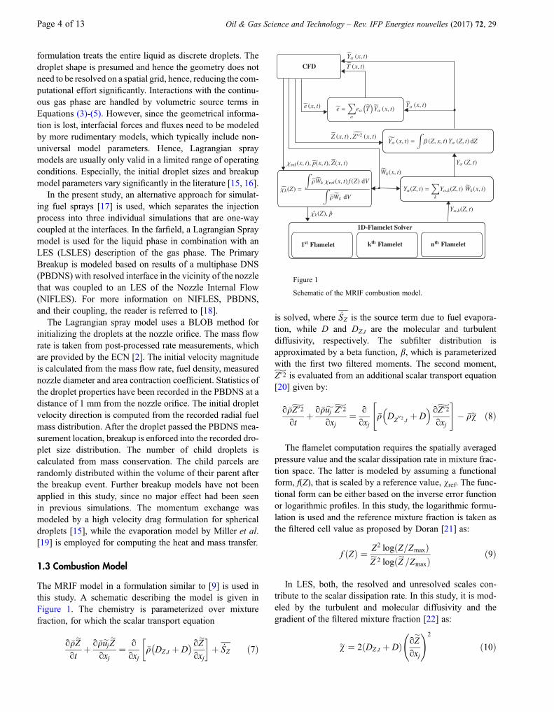
The MRIF model in a formulation similar to [9] is used inthis study. A schematic describing the model is given inFigure 1. The chemistry is parameterized over mixturefraction, for which the scalar transport equation
o�qZ�
otþ o�qu�jZ
�
oxj¼ o
oxj�q DZ;t þ D� � oZ�
oxj
� �þ _SZ ð7Þ
is solved, where _SZ is the source term due to fuel evapora-tion, while D and DZ,t are the molecular and turbulentdiffusivity, respectively. The subfilter distribution isapproximated by a beta function, b, which is parameterizedwith the first two filtered moments. The second moment,Z�002 is evaluated from an additional scalar transport equation[20] given by:
o�qZ�002
otþ o�qu�j Z
�002
oxj¼ o
oxj
"�q DZ
002;t þ D� oZ�002
oxj
#� �qv� ð8Þ
The flamelet computation requires the spatially averagedpressure value and the scalar dissipation rate in mixture frac-tion space. The latter is modeled by assuming a functionalform, f(Z), that is scaled by a reference value, vref. The func-tional form can be either based on the inverse error functionor logarithmic profiles. In this study, the logarithmic formu-lation is used and the reference mixture fraction is taken asthe filtered cell value as proposed by Doran [21] as:
f ðZÞ ¼ Z2 logðZ=ZmaxÞZ�2 logðZ�=ZmaxÞ
ð9Þ
In LES, both, the resolved and unresolved scales con-tribute to the scalar dissipation rate. In this study, it is mod-eled by the turbulent and molecular diffusivity and thegradient of the filtered mixture fraction [22] as:
v� ¼ 2ðDZ;t þ DÞ oZ�
oxj
!2
ð10Þ
Figure 1
Schematic of the MRIF combustion model.
Page 4 of 13 Oil & Gas Science and Technology – Rev. IFP Energies nouvelles (2017) 72, 29
The reference scalar dissipation rate can then be com-puted by:
vref ¼v�R
f Zð Þb Zð ÞdZ ð11Þ
In spray combustion, the scalar dissipation rate evolves intime from high values at the nozzle orifice towards lowvalues farther downstream. However, this evolution cannotbe captured in a single flamelet model, since the spatialinformation is lost due to conditional averaging into mixturefraction space. For the multiple flamelet model, the injectedfuel is splitted into n portions, which are attributed toindividual time intervals. The fuel portions are tracked byn � 1 additional scalar transport equations, Mk, in the flowdomain by the equation:
o�qM�
k
otþ o�qu�j M
�k
oxj¼ o
oxj
"�q DMk ;t þ D� � oM�k
oxj
#þ _SMk
ð12Þ
Here, _SMk is again the evaporation source term, which is
equal to _SZ within the time interval k and zero at all othertimes. The marker value of the last flamelet can then becomputed by an analytical relation arising from massconservation:
Z� ¼
Xk
M�
k ð13Þ
Furthermore, the turbulent diffusivities of the trackingscalars are determined as DMk ;t ¼ DZ;t. Based on the markerscalars, weighting factors can be defined that determine thespatial distribution of the flamelets by:
W�
k ¼ M�
k
Z� ð14Þ
By considering those weighting scalars within the condi-tional averaging, the spatially varying nature of the scalardissipation rate can be retained. Furthermore, the weightingfactors are used for combining the species solutions of allflamelets to the local cell values by linear combination.The flamelet computations are started at the beginning ofits corresponding marker injection interval in order to cap-ture different fuel residence times. The filtered species massfractions are obtained by convoluting the laminar solutionwith the mixture fraction sub filter distribution. The filteredtemperature is then iterated from the transported energy andfiltered species composition. It should be noted that theflamelets are computed separately and do not exchangeadditionally information. Thus, mixing effects of subse-quently injected fuel is only considered through the linearcombination of flamelet solutions, but not in the chemistry
calculation itself. Hence, if the combustion process isstrongly affected by reaction products of previously injectedfuel (e.g., in split injection cases), further model extensionsmight be required.
1.4 Numerical Framework
The simulations were performed with the in-house codeCIAO, which is a structured, high-order, finite differencecode that features both, a fully compressible and a low-Machnumber solver. The flow variables are staggered in spaceallowing higher discretization accuracy for a given stencilsize. The compressible solver was applied for all simulationsin this study. It employs an explicit five-stage Runge-Kuttaintegration scheme in time. The momentum equations arediscretized by central differences resulting in low numericaldissipation. All scalars are discretized by Weighted Essen-tially NonOscillatory (WENO) schemes ensuring boundedsolutions [23]. A more detailed description of the flow solveris given in Desjardins et al. [24] and Mittal et al. [25].
The droplet equations are advanced prior to the gas phase ina frozenflowfield using a2ndorderRunge-Kutta schemewithadaptive time-stepping. The statistical parcel method [26],which pools droplets of similar quantities into so-calledparcels, was used to reduce the computational effort. Thesource terms in the gas phase equations arising from theliquid droplets are distributed using a Gaussian distributionkernel [27] reducing mesh dependence and increasingnumerical stability. An in-house combustion library was usedas flamelet solver, which is parallelized in mixture fractionspace. Theflamelet equations are advanced after theflowfieldintegration. The scalar dissipation rate is linearly interpolatedin time when solving the flamelet. All flamelets weredistributed equally to the total number of processors andsolved simultaneously in order to minimize load imbalance.
2 SIMULATION SETUP
2.1 Simulation Cases
The simulation cases correspond to experimental studies thatwere conducted in a constant volume pre-burn spraychamber at Sandia National Laboratories. The experimentaldata is provided via the ECN data platform [2]. A detaileddescription of the experimental setup can be found in[28-30]. The experimental initial and boundary conditionsare summarized in Table 1.
2.2 Numerical Setup
Both simulations were performed on the same numericalgrid with a minimum grid spacing of 60 lm at the nozzle
Oil & Gas Science and Technology – Rev. IFP Energies nouvelles (2017) 72, 29 Page 5 of 13
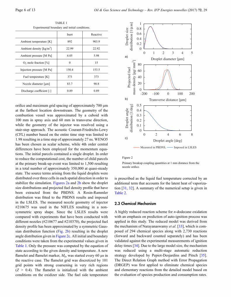
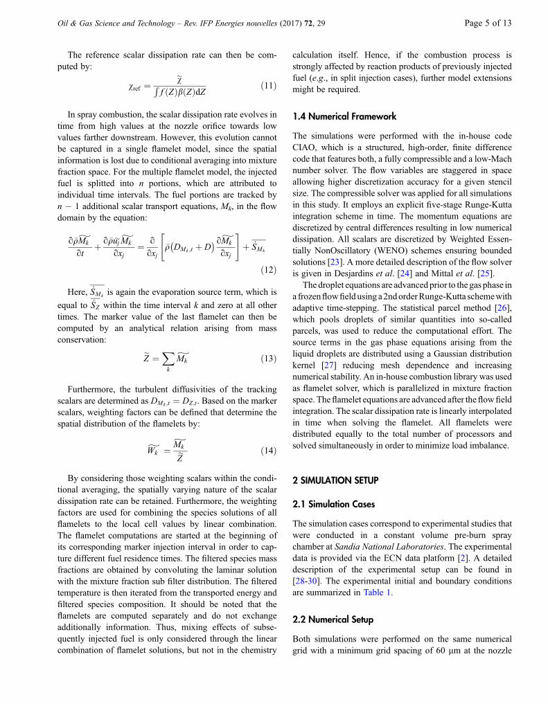
orifice and maximum grid spacing of approximately 700 lmat the farthest location downstream. The geometry of thecombustion vessel was approximated by a cuboid with100 mm in spray axis and 60 mm in transverse direction,while the geometry of the injector was resolved using astair-step approach. The acoustic Courant-Friedrichs-Lewy(CFL) number based on the entire time step was limited to1.98 resulting in a time step of approximately 27 ns. WENO5has been chosen as scalar scheme, while 4th order centraldifferences have been employed for the momentum equa-tions. The initial parcels contained a single droplet. In orderto reduce the computational cost, the number of child parcelsat the primary break-up event was limited to 1,500 resultingin a total number of approximately 350,000 at quasi-steadystate. The source terms arising from the liquid droplets weredistributed over three cells in each spatial direction in order tostabilize the simulation. Figures 2a and 2b show the dropletsize distributions and projected fuel density profile that havebeen extracted from the PBDNS. A Rosin-Rammlerdistribution was fitted to the PBDNS results and imposedin the LSLES. The measured nozzle geometry of injector#210675 was used in the NIFLES resulting in a non-symmetric spray shape. Since the LSLES results werecompared with experiments that have been conducted withdifferent nozzles (#210677 and #210370), the projected fueldensity profile has been approximated by a symmetric Gaus-sian distribution function (Fig. 2b) resulting in the dropletangle distribution given in Figure 2c. All initial and boundaryconditions were taken from the experimental values given inTable 1. Only the pressure was computed by the equation ofstate according to the given density and temperature. A newflamelet and flamelet marker, Mk, was started every 60 ls inthe reactive case. The flamelet grid was discretized by 101grid points with strong coarsening in very rich regions(Z > 0.4). The flamelet is initialized with the ambientconditions on the oxidizer side. The fuel side temperature
is prescribed as the liquid fuel temperature corrected by anadditional term that accounts for the latent heat of vaporiza-tion [31, 32]. A summary of the numerical setup is given inTable 2.
2.3 Chemical Mechanism
A highly reduced reaction scheme for n-dodecane oxidationwith an emphasis on prediction of auto-ignition process wasapplied in this study. The reduced model was derived fromthe mechanism of Narayanaswamy et al. [33], which is com-posed of 294 chemical species along with 2,730 reactions(forward and backward counted separately) and has beenvalidated against the experimental measurements of ignitiondelay times [34]. Due to the large model size, the mechanismwas reduced using a multi-stage automatic reductionstrategy developed by Pepiot-Desjardins and Pitsch [35].The Direct Relation Graph method with Error Propagation(DRGEP) was first applied to eliminate chemical speciesand elementary reactions from the detailed model based onthe evaluation of species production and consumption rates.
TABLE 1
Experimental boundary and initial conditions.
Inert Reactive
Ambient temperature [K] 892 903.9
Ambient density [kg/m3] 22.99 22.92
Ambient pressure [M Pa] 6.05 5.98
O2 mole fraction [%] 0 15
Injection pressure [M Pa] 150.4 153.5
Fuel temperature [K] 373 373
Nozzle diameter [lm] 83.7 90.8
Discharge coefficient [-] 0.89 0.89
00.20.40.60.8
1
0 1 2 3 4 5
Dro
plet
size
dist
ribu
tion
[1/μ
m]
Droplet diameter [μm]
0
20
40
60
80
-200 -100 0 100 200
Proj
ecte
dfu
elm
ass
dens
ity[μ
g/m
m2]
Transverse distance [μm]
00.10.20.30.40.5
0 2 4 6 8
Dro
plet
angl
edi
stri
butio
n[1
/deg
]
Droplet angle [deg]
Measured in PBDNS, Imposed in LSLES
a)
b)
c)
Figure 2
Primary breakup coupling quantities at 1 mm distance from thenozzle orifice.
Page 6 of 13 Oil & Gas Science and Technology – Rev. IFP Energies nouvelles (2017) 72, 29
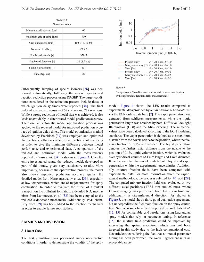
Subsequently, lumping of species isomers [36] was per-formed automatically, following the second species andreaction reduction process using DRGEP. The target condi-tions considered in the reduction process include those atwhich ignition delay times were reported [34]. The finalreduced mechanism consists of 57 species and 217 reactions.While a strong reduction of model size was achieved, it alsoleads unavoidably to deteriorated model prediction accuracy.Therefore, an automatic model optimization process wasapplied to the reduced model for improved prediction accu-racy of ignition delay times. The model optimization methoddeveloped by Frenklach [37] was employed and optimizedthe reaction coefficients of sensitive reactions automaticallyin order to give the minimum difference between modelperformance and experimental data. A comparison of thereduced and optimized model with the measurementsreported by Vasu et al. [34] is shown in Figure 3. Over theentire investigated range, the reduced model, developed aspart of this study, gives very satisfactory results. Moreimportantly, because of the optimization process, the modelalso shows improved prediction accuracy against thedetailed model from Narayanaswamy et al. [33], especiallyat low temperatures, which are of major interest for spraycombustion. In order to evaluate the effect of turbulenttransport on the pollutant formation, a detailed NOx mecha-nism from Lamoureux et al. [38] has been coupled to thereduced n-dodecane mechanism. Additionally, PAH chem-istry from [39] has been added to the reaction mechanismin order to enable future soot studies.
3 RESULTS AND DISCUSSION
3.1 Inert Case
The first simulation was performed under non-reactiveconditions in order to demonstrate the validity of the spray
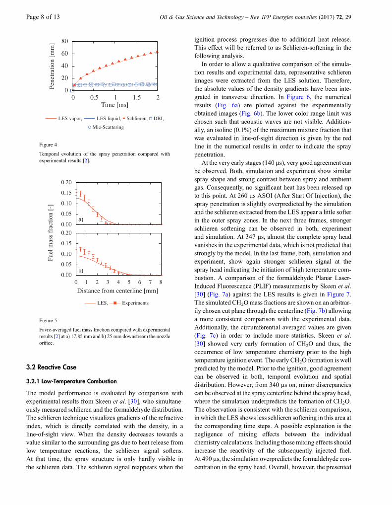
model. Figure 4 shows the LES results compared toexperimental data provided by Sandia National Laboratoriesvia the ECN online data base [2]. The vapor penetration wasextracted from schlieren measurements, while the liquidpenetration length was obtained by both, Diffusive BacklightIllumination (DBI) and the Mie-Scattering. The numericalvalues have been calculated according to the ECN modelingstandards. The vapor penetration is defined as the maximumdistance from the nozzle orifice to the position, where the fuelmass fraction of 0.1% is exceeded. The liquid penetrationdenotes the farthest axial distance from the nozzle to theposition of 0.1% liquid volume fraction, which is evaluatedover cylindrical volumes of 1 mm length and 1 mm diameter.It can be seen that the model predicts both, liquid and vaporpenetration within the experimental uncertainties. Addition-ally, mixture fraction fields have been compared withexperimental data. For more information about the experi-mental methodology, the reader is referred to [40] and [29].The computed mixture fraction field was evaluated at twodifferent axial positions (17.85 mm and 25 mm), whereFavre-averaging was performed from 1-2 ms in time andadditionally in circumferential direction. As shown inFigure 5, the model shows fairly good qualitative agreement,but underpredicts the fuel mass fraction on the spray center-line. Similar results have been reported by Wehrfritz et al.[12, 15] for comparable grid resolutions using Lagrangianspray models that rely on parameter tuning. In reference[15], the mixture field prediction could be improved byincreasing the spatial resolution, which has not beentargeted in this study due to the high computational cost.Nevertheless, considering the fact that no model parametertuning has been performed, the overall agreement is in anacceptable range.
0.01
0.1
1
10
0.6 0.8 1 1.2 1.4 1.6
Igni
tion
dela
y[m
s]
Inverse temperature [1000 / K]
Present study P = 20.3 bar, φ =1.0Narayanaswamy [33] P = 20.3 bar, φ =1.0Vasu [34] P = 20.3 bar, φ =1.0Present study P = 20.3 bar, φ =0.5Narayanaswamy [33] P = 20.3 bar, φ =0.5Vasu [34] P = 20.3 bar, φ =0.5
Figure 3
Comparison of baseline mechanism and reduced mechanismwith experimental ignition delay measurements.
TABLE 2
Numerical setup.
Minimum grid spacing [lm] 60
Maximum grid spacing [lm] 700
Grid dimensions [mm] 100 9 60 9 60
Number of cells [-] 29.5e6
Number of parcels [-] 350e3
Number of flamelets [-] 26 (1.5 ms)
Flamelet grid points [-] 101
Time step [ns] 27
Oil & Gas Science and Technology – Rev. IFP Energies nouvelles (2017) 72, 29 Page 7 of 13
3.2 Reactive Case
3.2.1 Low-Temperature Combustion
The model performance is evaluated by comparison withexperimental results from Skeen et al. [30], who simultane-ously measured schlieren and the formaldehyde distribution.The schlieren technique visualizes gradients of the refractiveindex, which is directly correlated with the density, in aline-of-sight view. When the density decreases towards avalue similar to the surrounding gas due to heat release fromlow temperature reactions, the schlieren signal softens.At that time, the spray structure is only hardly visible inthe schlieren data. The schlieren signal reappears when the
ignition process progresses due to additional heat release.This effect will be referred to as Schlieren-softening in thefollowing analysis.
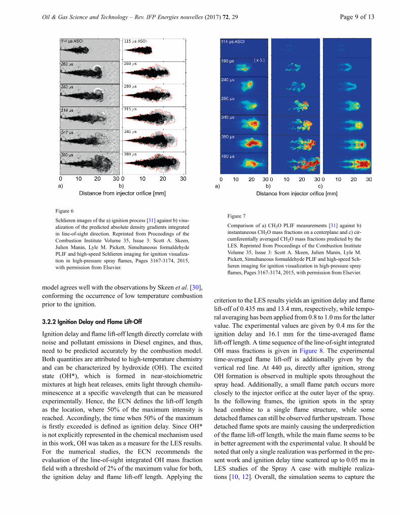
In order to allow a qualitative comparison of the simula-tion results and experimental data, representative schlierenimages were extracted from the LES solution. Therefore,the absolute values of the density gradients have been inte-grated in transverse direction. In Figure 6, the numericalresults (Fig. 6a) are plotted against the experimentallyobtained images (Fig. 6b). The lower color range limit waschosen such that acoustic waves are not visible. Addition-ally, an isoline (0.1%) of the maximum mixture fraction thatwas evaluated in line-of-sight direction is given by the redline in the numerical results in order to indicate the spraypenetration.
At the very early stages (140 ls), very good agreement canbe observed. Both, simulation and experiment show similarspray shape and strong contrast between spray and ambientgas. Consequently, no significant heat has been released upto this point. At 260 ls ASOI (After Start Of Injection), thespray penetration is slightly overpredicted by the simulationand the schlieren extracted from the LES appear a little softerin the outer spray zones. In the next three frames, strongerschlieren softening can be observed in both, experimentand simulation. At 347 ls, almost the complete spray headvanishes in the experimental data, which is not predicted thatstrongly by the model. In the last frame, both, simulation andexperiment, show again stronger schlieren signal at thespray head indicating the initiation of high temperature com-bustion. A comparison of the formaldehyde Planar Laser-Induced Fluorescence (PLIF) measurements by Skeen et al.[30] (Fig. 7a) against the LES results is given in Figure 7.The simulated CH2Omass fractions are shown on an arbitrar-ily chosen cut plane through the centerline (Fig. 7b) allowinga more consistent comparison with the experimental data.Additionally, the circumferential averaged values are given(Fig. 7c) in order to include more statistics. Skeen et al.[30] showed very early formation of CH2O and thus, theoccurrence of low temperature chemistry prior to the hightemperature ignition event. The early CH2O formation is wellpredicted by the model. Prior to the ignition, good agreementcan be observed in both, temporal evolution and spatialdistribution. However, from 340 ls on, minor discrepanciescan be observed at the spray centerline behind the spray head,where the simulation underpredicts the formation of CH2O.The observation is consistent with the schlieren comparison,in which the LES shows less schlieren softening in this area atthe corresponding time steps. A possible explanation is thenegligence of mixing effects between the individualchemistry calculations. Including thosemixing effects shouldincrease the reactivity of the subsequently injected fuel.At 490 ls, the simulation overpredicts the formaldehyde con-centration in the spray head. Overall, however, the presented
0.00
0.05
0.10
0.15
0.20
Fuel
mas
sfr
actio
n[-
]
0.00
0.05
0.10
0.15
0.20
0 1 2 3 4 5 6 7 8
Distance from centerline [mm]
LES, Experiments
a)
b)
Figure 5
Favre-averaged fuel mass fraction compared with experimentalresults [2] at a) 17.85 mm and b) 25 mm downstream the nozzleorifice.
0
20
40
60
80
0 0.5 1 1.5 2
Pene
trat
ion
[mm
]
Time [ms]
LES vapor, LES liquid, Schlieren, DBI,
Mie-Scattering
Figure 4
Temporal evolution of the spray penetration compared withexperimental results [2].
Page 8 of 13 Oil & Gas Science and Technology – Rev. IFP Energies nouvelles (2017) 72, 29
model agrees well with the observations by Skeen et al. [30],conforming the occurrence of low temperature combustionprior to the ignition.
3.2.2 Ignition Delay and Flame Lift-Off
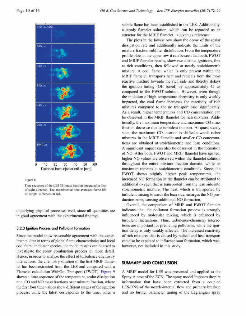
Ignition delay and flame lift-off length directly correlate withnoise and pollutant emissions in Diesel engines, and thus,need to be predicted accurately by the combustion model.Both quantities are attributed to high-temperature chemistryand can be characterized by hydroxide (OH). The excitedstate (OH*), which is formed in near-stoichiometricmixtures at high heat releases, emits light through chemilu-minescence at a specific wavelength that can be measuredexperimentally. Hence, the ECN defines the lift-off lengthas the location, where 50% of the maximum intensity isreached. Accordingly, the time when 50% of the maximumis firstly exceeded is defined as ignition delay. Since OH*is not explicitly represented in the chemical mechanism usedin this work, OH was taken as a measure for the LES results.For the numerical studies, the ECN recommends theevaluation of the line-of-sight integrated OH mass fractionfield with a threshold of 2% of the maximum value for both,the ignition delay and flame lift-off length. Applying the
criterion to the LES results yields an ignition delay and flamelift-off of 0.435 ms and 13.4 mm, respectively, while tempo-ral averaging has been applied from 0.8 to 1.0ms for the lattervalue. The experimental values are given by 0.4 ms for theignition delay and 16.1 mm for the time-averaged flamelift-off length. A time sequence of the line-of-sight integratedOH mass fractions is given in Figure 8. The experimentaltime-averaged flame lift-off is additionally given by thevertical red line. At 440 ls, directly after ignition, strongOH formation is observed in multiple spots throughout thespray head. Additionally, a small flame patch occurs moreclosely to the injector orifice at the outer layer of the spray.In the following frames, the ignition spots in the sprayhead combine to a single flame structure, while somedetached flames can still be observed further upstream. Thosedetached flame spots are mainly causing the underpredictionof the flame lift-off length, while the main flame seems to bein better agreement with the experimental value. It should benoted that only a single realization was performed in the pre-sent work and ignition delay time scattered up to 0.05 ms inLES studies of the Spray A case with multiple realiza-tions [10, 12]. Overall, the simulation seems to capture the
a) b) c)
Figure 7
Comparison of a) CH2O PLIF measurements [31] against b)instantaneous CH2O mass fractions on a centerplane and c) cir-cumferentially averaged CH2O mass fractions predicted by theLES. Reprinted from Proceedings of the Combustion InstituteVolume 35, Issue 3: Scott A. Skeen, Julien Manin, Lyle M.Pickett, Simultaneous formaldehyde PLIF and high-speed Sch-lieren imaging for ignition visualization in high-pressure sprayflames, Pages 3167-3174, 2015, with permission from Elsevier.
a) b)
Figure 6
Schlieren images of the a) ignition process [31] against b) visu-alization of the predicted absolute density gradients integratedin line-of-sight direction. Reprinted from Proceedings of theCombustion Institute Volume 35, Issue 3: Scott A. Skeen,Julien Manin, Lyle M. Pickett, Simultaneous formaldehydePLIF and high-speed Schlieren imaging for ignition visualiza-tion in high-pressure spray flames, Pages 3167-3174, 2015,with permission from Elsevier.
Oil & Gas Science and Technology – Rev. IFP Energies nouvelles (2017) 72, 29 Page 9 of 13
underlying physical processes well, since all quantities arein good agreement with the experimental findings.
3.2.3 Ignition Process and Pollutant Formation
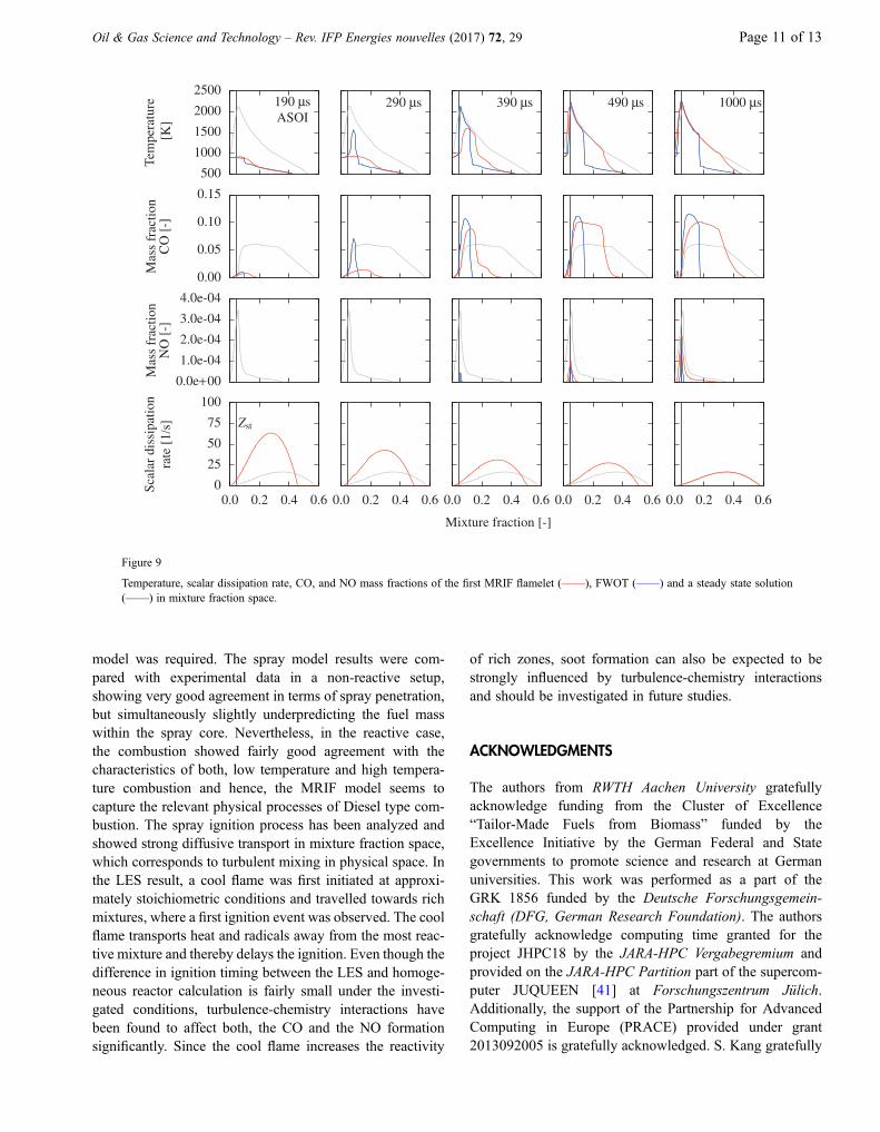
Since the model show reasonable agreement with the exper-imental data in terms of global flame characteristics and localcool flame indicator species, the model results can be used toinvestigate the spray combustion process in more detail.Hence, in order to analyze the effect of turbulence-chemistryinteractions, the chemistry solution of the first MRIF flame-let has been extracted from the LES and compared with aFlamelet calculation WithOut Transport (FWOT). Figure 9shows a time sequence of the temperature, scalar dissipationrate, CO and NOmass fractions over mixture fraction, wherethe first four time values show different stages of the ignitionprocess, while the latest corresponds to the time, when a
stabile flame has been established in the LES. Additionally,a steady flamelet solution, which can be regarded as anattractor for the MRIF flamelet, is given as reference.
The plots in the lowest row show the decay of the scalardissipation rate and additionally indicate the limits of themixture fraction subfilter distribution. From the temperatureprofile plots in the upper row it can be seen that both, FWOTand MRIF flamelet results, show two distinct ignitions, firstat rich conditions, then followed at nearly stoichiometricmixture. A cool flame, which is only present within theMRIF flamelet, transports heat and radicals from the mostreactive mixture towards the rich side and thereby delaysthe ignition timing (OH based) by approximately 45 lscompared to the FWOT solution. However, even thoughthe initiation of high-temperature chemistry is only weaklyimpacted, the cool flame increases the reactivity of richmixtures compared to the no transport case significantly.As a result, higher temperatures and CO concentration canbe observed in the MRIF flamelet for rich mixtures. Addi-tionally, the maximum temperature and maximum CO massfraction decrease due to turbulent tranport. At quasi-steadystate, the maximum CO location is shifted towards richermixtures in the MRIF flamelet and smaller CO concentra-tions are obtained at stoichiometric and lean conditions.A significant impact can also be observed in the formationof NO. After both, FWOT and MRIF flamelet have ignited,higher NO values are observed within the flamelet solutionthroughout the entire mixture fraction domain, while itsmaximum remains at stoichiometric conditions. Since, theFWOT shows slightly higher peak temperatures, theincreased NO formation in the flamelet can be attributed toadditional oxygen that is transported from the lean side intostoichiometric mixture. The heat, which is transported byturbulent mixing towards the lean side, enlarges the NO pro-duction zone, causing additional NO formation.
Overall, the comparison of MRIF and FWOT flameletindicates that the pollutant formation process is stronglyinfluenced by molecular mixing, which is enhanced byturbulent fluctuations. Thus, turbulence-chemistry interac-tions are important for predicting pollutants, while the igni-tion delay is only weakly affected. The increased reactivityof rich mixtures that is caused by radical and heat transportcan also be expected to influence soot formation, which was,however, not included in this study.
SUMMARY AND CONCLUSION
A MRIF model for LES was presented and applied to theSpray A case of the ECN. The spray model imposes dropletinformation that have been extracted from a coupledLES/DNS of the nozzle-internal flow and primary breakupand no further parameter tuning of the Lagrangian spray
Figure 8
Time sequence of the LES OH mass fraction integrated in line-of-sight direction. The experimental time-averaged flame lift-off length is marked in red.
Page 10 of 13 Oil & Gas Science and Technology – Rev. IFP Energies nouvelles (2017) 72, 29
model was required. The spray model results were com-pared with experimental data in a non-reactive setup,showing very good agreement in terms of spray penetration,but simultaneously slightly underpredicting the fuel masswithin the spray core. Nevertheless, in the reactive case,the combustion showed fairly good agreement with thecharacteristics of both, low temperature and high tempera-ture combustion and hence, the MRIF model seems tocapture the relevant physical processes of Diesel type com-bustion. The spray ignition process has been analyzed andshowed strong diffusive transport in mixture fraction space,which corresponds to turbulent mixing in physical space. Inthe LES result, a cool flame was first initiated at approxi-mately stoichiometric conditions and travelled towards richmixtures, where a first ignition event was observed. The coolflame transports heat and radicals away from the most reac-tive mixture and thereby delays the ignition. Even though thedifference in ignition timing between the LES and homoge-neous reactor calculation is fairly small under the investi-gated conditions, turbulence-chemistry interactions havebeen found to affect both, the CO and the NO formationsignificantly. Since the cool flame increases the reactivity
of rich zones, soot formation can also be expected to bestrongly influenced by turbulence-chemistry interactionsand should be investigated in future studies.
ACKNOWLEDGMENTS
The authors from RWTH Aachen University gratefullyacknowledge funding from the Cluster of Excellence“Tailor-Made Fuels from Biomass” funded by theExcellence Initiative by the German Federal and Stategovernments to promote science and research at Germanuniversities. This work was performed as a part of theGRK 1856 funded by the Deutsche Forschungsgemein-schaft (DFG, German Research Foundation). The authorsgratefully acknowledge computing time granted for theproject JHPC18 by the JARA-HPC Vergabegremium andprovided on the JARA-HPC Partition part of the supercom-puter JUQUEEN [41] at Forschungszentrum Jülich.Additionally, the support of the Partnership for AdvancedComputing in Europe (PRACE) provided under grant2013092005 is gratefully acknowledged. S. Kang gratefully
500
1000
1500
2000
2500
Tem
pera
ture
[K]
190 μsASOI
290 μs 390 μs 490 μs 1000 μs
0.00
0.05
0.10
0.15
Mas
sfr
actio
nC
O[-
]
0.0e+00
1.0e-04
2.0e-04
3.0e-04
4.0e-04
Mas
sfr
actio
nN
O[-
]
0
25
50
75
100
0.0 0.2 0.4 0.6
Scal
ardi
ssip
atio
nra
te[1
/s]
Mixture fraction [-]
Zst
0.0 0.2 0.4 0.6 0.0 0.2 0.4 0.6 0.0 0.2 0.4 0.6 0.0 0.2 0.4 0.6
Figure 9
Temperature, scalar dissipation rate, CO, and NO mass fractions of the first MRIF flamelet (––––), FWOT (––––) and a steady state solution(––––) in mixture fraction space.
Oil & Gas Science and Technology – Rev. IFP Energies nouvelles (2017) 72, 29 Page 11 of 13
acknowledges the financial support from the NationalResearch Council of Science & Technology (NST) grant bythe Korea government (MSIP) (No. CRC-15-07-KIER).
REFERENCES
1 Kalghatgi G.T. (2014). Developments in internal combustionengines and implications for combustion science and futuretransport fuels, Proc. Combust. Inst. 35, 101-115.
2 URL https://ecn.sandia.gov
3 Pope S.B. (1985) PDF methods for turbulent reactive flows,Prog. Energy Combust. Sci. 11, 2, 119-192.
4 Klimenko A.Y., Bilger R.W. (1999) Conditional momentclosure for turbulent combustion, Prog. Energy Combust. Sci.25, 6, 595-687.
5 Peters N. (1984) Laminar diffusion flamelet models in non-premixed turbulent combustion, Prog. Energy Combust. Sci.10, 3, 319-339.
6 Pitsch H., Wan Y.P., Peters N. (1995) Numerical investigationof soot formation and oxidation under Diesel engine conditions,SAE Technical Paper 952357.
7 Pitsch H., Chen M., Peters N. (1998) Unsteady flameletmodeling of turbulent hydrogen-air diffusion flames, Symp.Int. Combust. 27, 1, 1057-1064.
8 Barths H., Hasse C., Bikas G., Peters N. (2000) Simulation ofcombustion in direct injection Diesel engines using a Eulerianparticle flamelet model, Proc. Combust. Inst. 28, 1, 1161-1168.
9 D’Errico G., Lucchini T., Contino F., Jangi M., Bai X.S. (2014)Comparison of well-mixed and multiple representativeinteractive flamelet approaches for Diesel spray combustionmodelling, Combust. Theor. Model. 18, 1, 65-88.
10 Pei Y., Som S., Pomraning E., Senecal P.K., Skeen S.A., Manin J.,Pickett L.M. (2015) Large eddy simulation of a reacting sprayflame with multiple realizations under compression ignitionengine conditions, Combust. Flame 162, 12, 4442-4455.
11 Blomberg C.K., Zeugin L., Pandurangi S.S., Bolla M.,Boulouchos K., Wright Y.M. (2016) Modeling split injectionsof ECN “Spray A” using a conditional moment closurecombustion model with RANS and LES, SAE Int. J. Engines9, 2107-2119.
12 Wehrfritz A., Kaario O., Vuorinen V., Somers B. (2016) Largeeddy simulation of n-dodecane spray flames using flameletgenerated manifolds, Combust. Flame 167, 113-131.
13 Bekdemir C., Somers L.M.T., de Goey L.P.H., Tillou J.,Angelberger C. (2013) Predicting Diesel combustion character-istics with large-eddy simulations including tabulated chemicalkinetics, Proc. Combust. Inst. 34, 2, 3067-3074.
14 Germano M., Piomelli U., Moin P., Cabot W.H. (1991) Adynamic subgrid-scale eddy viscosity model, Phys. Fluids A:Fluid Dyn. 3, 7, 1760-1765.
15 Wehrfritz A., Vuorinen V., Kaario O., Larmi M. (2013) Largeeddy simulation of high-velocity fuel sprays: studying meshresolution and breakup model effects for spray A, AtomizationSprays 23, 5, 419-442.
16 Senecal P.K., Pomraning E., Xue Q., Som S., Banerjee S.,Hu B., Liu K., Deur J.M. (2014) Large eddy simulation ofvaporizing sprays considering multi-injection averaging andgrid-convergent mesh resolution, J. Eng. Gas Turbines Power136, 11, 111504.
17 Bode M., Falkenstein T., Le Chenadec V., Kang S., Pitsch H.,Arima T., Taniguchi H. (2015) A new Euler/Lagrange approachfor multiphase simulations of a multi-hole GDI injector, SAETechnical Paper. 2015-01-0949. SAE International.
18 Bode M., Davidovic M., Pitsch H. (2017) Multi-scale couplingfor predictive injector simulations, Springer InternationalPublishing, Cham, Switzerland, pp. 96-108.
19 Miller R.S., Harstad K., Bellan J. (1998) Evaluation ofequilibrium and non-equilibrium evaporation models formany-droplet gas-liquid flow simulations, Int. J. MultiphaseFlow 24, 6, 1025-1055.
20 Raman V., Pitsch H., Fox R.O. (2006) Eulerian transportedprobability density function sub-filter model for large-eddysimulations of turbulent combustion, Combust. Theor. Model.10, 3, 439-458.
21 Doran E.M. (2011) A multi-dimensional flamelet model forignition in multi-feed combustion systems, PhD Thesis,Stanford University, Stanford, CA.
22 Pitsch H., Steiner H. (2000) Scalar mixing and dissipation ratein large-eddy simulations of non-premixed turbulentcombustion, Proc. Combust. Inst. 28, 1, 41-49.
23 Liu X.-D., Osher S., Chan T. (1994) Weighted essentiallynonoscillatory schemes, J. Comput. Phys. 115, 1, 200-212.
24 Desjardins O., Blanquart G., Balarac G., Pitsch H. (2008) Highorder conservative finite difference scheme for variable densitylow Mach number turbulent flows, J. Comput. Phys. 227, 15,7125-7159.
25 Mittal V., Kang S., Doran E., Cook D., Pitsch H. (2014) LES ofgas exchange in IC engines, Oil Gas Sci. Technol. – Rev. IFP69, 1, 29-40.
26 Dukowicz J.K. (1980) A particle-fluid numerical model forliquid sprays, J. Comput. Phys. 35, 2, 229-253.
27 Apte S.V., Mahesh K., Lundgren T. (2008) Accounting forfinite-size effects in simulations of disperse particle-ladenflows, Int. J. Multiphase Flow 34, 3, 260-271.
28 Pickett L.M., Genzale C.L., Bruneaux G., MalbecL.-M., Hermant L., Christiansen C., Schramm J. (2010)Comparison of Diesel spray combustion in different high-temperature, high-pressure facilities, SAE Int. J. Engines 3,156-181.
29 Pickett L.M., Manin J., Genzale C.L., Siebers D.L.,Musculus M.P.B., Idicheria C.A. (2011) Relationshipbetween Diesel fuel spray vapor penetration/dispersionand local fuel mixture fraction, SAE Int. J. Engines 4,764-799.
30 Skeen S.A., Manin J., Pickett L.M. (2015) Simultaneousformaldehyde PLIF and high-speed schlieren imaging forignition visualization in high-pressure spray flames, Proc.Combust. Inst. 35, 3, 3167-3174.
31 Knudsen E., Shashank, Pitsch H. (2015) Modeling partiallypremixed combustion behavior in multiphase LES, Combust.Flame 162, 1, 159-180.
32 Ham F., Apte S., Iaccarino G., Wu X., Herrmann M.,Constantinescu G., Mahesh K., Moin P. (2003)Unstructured LES of reacting multiphase flows in realisticgas turbine combustors, in CTR annual research briefs,pp. 139-160.
33 Narayanaswamy K., Pepiot P., Pitsch H. (2014) A chemicalmechanism for low to high temperature oxidation ofn-dodecane as a component of transportation fuel surrogates,Combust. Flame 161, 4, 866-884.
Page 12 of 13 Oil & Gas Science and Technology – Rev. IFP Energies nouvelles (2017) 72, 29
34 Vasu S.S., Davidson D.F., Hong Z., Vasudevan V., Hanson R.K. (2009) N-dodecane oxidation at high-pressures: Measure-ments of ignition delay times and OH concentration time-histories, Proc. Combust. Inst. 32, 1, 173-180.
35 Pepiot-Desjardins P., Pitsch H. (2008) An efficient errorpropagation-based reduction method for large chemical kineticmechanisms, Combust. Flame 154, 67-81.
36 Pepiot-Desjardins P., Pitsch H. (2008) An automatic chemicallumping method for the reduction of large chemical kineticmechanisms, Combust. Theor. Model. 12, 6, 1089-1108.
37 Frenklach M. (1984) Systematic optimization of a detailedkinetic model using a methane ignition example, Combust.Flame 58, 1, 69-72.
38 Lamoureux N., Desgroux P., El Bakali A., Pauwels J.F. (2010)Experimental and numerical study of the role of NCN inprompt-NO formation in low-pressure CH4–O2–N2 andC2H2–O2–N2 flames, Combust. Flame 157, 10, 1929-1941.
39 Narayanaswamy K., Blanquart G., Pitsch H. (2010) Aconsistent chemical mechanism for oxidation of substitutedaromatic species, Combust. Flame 157, 10, 1879-1898.
40 Idicheria C.A., Pickett L.M. (2007) Quantitative mixingmeasurements in a vaporizing Diesel spray by Rayleighimaging, SAE Technical Paper. 2007-01-0647. SAEInternational.
41 Jülich Supercomputing Centre (2015) JUQUEEN: IBM BlueGene/Q supercomputer system at the Jülich supercomputingcentre, Journal of Large-Scale Research Facilities 1, 1-5.
Manuscript submitted in February 2017
Manuscript accepted in June 2017
Published online in October 2017
Cite this article as:M. Davidovic, T. Falkenstein, M. Bode, L. Cai, S. Kang, J. Hinrichs and H. Pitsch (2017). LES of n-Dodecane SprayCombustion Using a Multiple Representative Interactive Flamelets Model, Oil Gas Sci. Technol
Oil & Gas Science and Technology – Rev. IFP Energies nouvelles (2017) 72, 29 Page 13 of 13