Embed Size (px)
Citation preview
Available online at www.sciencedirect.comProceedings
ScienceDirect
Proceedings of the Combustion Institute 35 (2015) 1549–1577
www.elsevier.com/locate/proci
of the
CombustionInstitute
The role of separation of scales in the descriptionof spray combustion
Antonio L. Sanchez a,⇑, Javier Urzay b, Amable Linan c
a Grupo de Mecanica de Fluidos, Universidad Carlos III de Madrid, Leganes 28911, Spainb Center for Turbulence Research, Stanford University, Stanford, CA 94305-3024, United States
c ETSI Aeronauticos, Pl. Cardenal Cisneros 3, Madrid 28040, Spain
Available online 17 September 2014
Abstract
The present paper deals with the description of the interacting multiscale processes governing sprayvaporization and combustion downstream from the near-injector atomization region in liquid-fueled burn-ers. One of the main objectives is to emphasize the progress made in the mathematical description andunderstanding of reactive spray flows by incorporation of rationally derived simplifications based on thedisparity of length and time scales present in the problem. In particular, we aim to show how the disparityof the scales that correspond – with increasing values of their orders of magnitude – to the droplet size,interdroplet spacing, and width of the spray jets, ensures the validity of their homogenized description.The two-way coupling associated with exchanges of mass, momentum, and energy between the gas andthe liquid phases is dominated by the homogenized exchanges with the gas provided collectively by thedroplets, and not by the direct interaction between neighboring droplets. The formulation is used as a basisto address nonpremixed spray diffusion flames in the Burke-Schumann limit of infinitely fast chemical reac-tions, with the conservation equations written in terms of chemistry-free coupling functions that allow forgeneral nonunity Lewis numbers of the fuel vapor. Laminar canonical problems that have been used in thepast to shed light on different aspects of spray-combustion phenomena are also discussed, including spher-ical spray clouds and structures of counterflow spray flames in mixing layers. The presentation ends with abrief account of some open problems and modeling challenges.� 2014 The Combustion Institute. Published by Elsevier Inc. All rights reserved.
Keywords: Separation of scales; Spray combustion; Liquid-fueled propulsion; Multiphase flows
1. Introduction
The existence of length and time scales of verydifferent magnitude is a complicating characteris-tic of many problems encountered in fluidmechanics and combustion. The mathematical
http://dx.doi.org/10.1016/j.proci.2014.08.0181540-7489/� 2014 The Combustion Institute. Published by El
⇑ Corresponding author.
description of the associated flows can be facili-tated by accounting for the disparity of thesescales. A renowned example of the success of thisapproach is the boundary-layer theory developedby Ludwig Prandtl over a century ago. Separationof scales has also been extensively used in connec-tion with the description of combustion problems,where the disparity of time scales is often due tothe strong temperature sensitivity of the chemical
sevier Inc. All rights reserved.
1550 A.L. Sanchez et al. / Proceedings of the Combustion Institute 35 (2015) 1549–1577
reactions. For spray combustion, additionallength and time scales originate from the two-phase nature of the flow.
Over the past half century combustion model-ers have successfully exploited the separation ofthe scales present in the vaporization and combus-tion of droplets and sprays to generate simplifiedequations for the description of reactive sprayflows. The purpose of this topical review lectureis to give an overview of the progress achievedand to describe some recent results. The presenta-tion will begin with a discussion of the reasons forthe validity, and also the shortcomings, of thecontinuum description of the gas and liquidphases in the vaporization and combustion ofsprays. Because of the important role of the inter-phase exchange rates of mass, energy, andmomentum, a summary of these rates is given,and then used in the conservation equations forthe description of reacting sprays; this simplifiesin the important extreme limiting cases of purespray vaporization, without chemical reactions,and diffusion-controlled spray combustion. Sim-ple laminar canonical problems, widely used inthe past in fundamental investigations of spraycombustion, are formulated in nondimensionalform to identify the parameters that characterizethe interplay of the different spray physicochemi-cal phenomena.
Substantial research efforts have been made inthe past in connection with the problems of vapor-ization and combustion of droplets and dropletarrays [1–9], ignition of fuel sprays [10], anddynamics and modeling of turbulent sprays [11–13]. Related work on atomization of liquid jets[14–16] and on the dynamics of particle-laden tur-bulent flows [17–19] is relevant for understandingthe generation and dispersion of sprays. A refer-ence book including an updated comprehensivepresentation of the current level of understandingof fluid dynamics and transport of droplets andsprays is available [20]. In addition, other relevantliterature include reference textbooks on atomiza-tion [21] and multiphase combustion [22], as wellas research monographs [23,24].
The design of liquid-fueled combustion sys-tems is subject to a number of constraints stem-ming from the need to vaporize the droplets,mix the fuel vapor with the surrounding air, andignite and burn completely the resulting mixturein the limited available residence time, with thescales and parameters of these different physico-chemical processes entering in the determinationof the combustor performance. An importantconsideration that must be taken into accountwhen describing vaporization and combustion indiesel engines, and also in the primary combustionzone of gas turbines, is the large value of theliquid-to-gas density ratio, on the order of a fewhundred in many applications. Also relevant forcombustion is the large value, of order S � 15,
of the mass of air required to burn in stoichiome-tric proportions the unit mass of fuel. Anotherbasic consideration pertaining to the required dis-persion of the droplets in the combustion chamberis that the heat needed for the vaporization ofeach droplet comes from the sensible heat of thegas within the spray, so that vaporization in thebulk of the spray can only start when sufficientlydilute conditions are reached; otherwise theamount of gas entrained by the spray is insuffi-cient to provide the heat of vaporization. Inassessing the coupling between the liquid andgas phases, one must also bear in mind that theheat released by burning the fuel is enough lo leadto flame temperatures several times larger than theinitial liquid temperature.
The large temperature sensitivity of the com-bustion reactions also enters in a fundamentalway. For instance, in continuous-combustiondevices this temperature sensitivity explains theonset of ignition near the hot boundary in mixinglayers separating the spray from the preheated air.An important consideration, relevant for theselection of the atomizer in a given application,is that the droplet size must be small enough toensure their complete vaporization and preventtheir impingement with the confining walls. Inview of the above considerations, it is clear thatspray combustion stands out as a very particularcategory within the general field of two-phaseflows, one that cannot be understood withoutaccounting for its distinctive attributes.
The remainder of this paper is organized as fol-lows. Some general comments concerning the spe-cific characteristic of spray flows in combustionapplications are given in Section 2, followed inSection 3 by a homogenized formulation for spraycombustion that will serve as analytical frame-work for the rest of the paper. A qualitativedescription of spray combustion phenomena ispresented in Section 4. The limit of infinitely fastchemical reaction is considered in Section 5, whichprovides a general Burke-Schumann formulationfor the computation of spray flames. Sections 6and 7 are devoted to the characterization of ele-mentary spray structures. The final section out-lines some of the open problems in spraycombustion, including modeling issues.
2. Preliminary considerations pertaining to sprayflows in combustion systems
2.1. Atomization in spray-combustion applications
The reduction in spray length required by thelimited size of the combustion chamber can onlybe accomplished when there exists a significantvelocity difference between the liquid jet or sheetto be atomized and the surrounding coflowinggas [21]. This is the case if the liquid stream is
A.L. Sanchez et al. / Proceedings of the Combustion Institute 35 (2015) 1549–1577 1551
injected at high velocity, as in pressure atomizersof diesel engines, or by exposing the liquid to ahigh-velocity air stream, the method used in air-assist and airblast atomizers. The hydrodynamicinstabilities involved in the breakup process, dif-ferent for pressure and airblast atomizers [14–16,20,25], lead to primary atomization of theliquid vein to form ligaments and droplets, whichfurther break up downstream as a result of theinteractions with the surrounding turbulent gas-eous flow in the secondary atomization region.
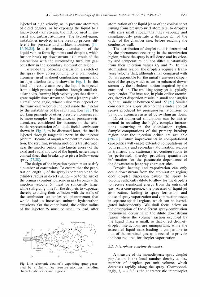
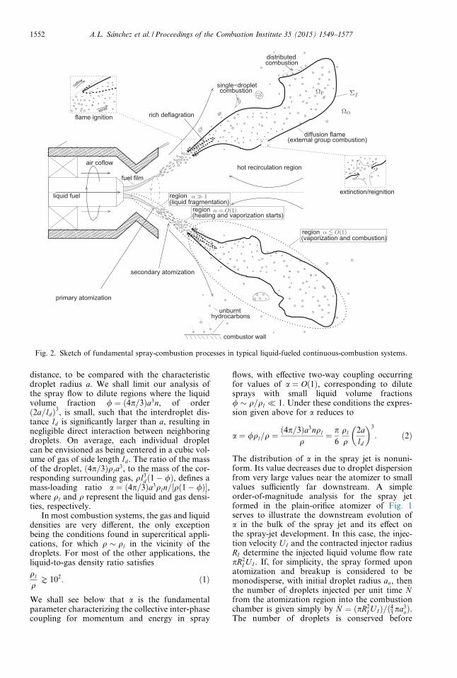
To guide the following discussion, a sketch ofthe spray flow corresponding to a plain-orificeatomizer, used in diesel combustion engines andturbojet afterburners, is shown in Fig. 1. In thiskind of pressure atomizer, the liquid is injectedfrom a high-pressure chamber through small cir-cular holes, forming high-velocity jets that disinte-grate rapidly downstream to form a jet spray witha small cone angle, whose value may depend onthe transverse velocities induced inside the injectorby the instabilities of the cavitating flow [26]. Theworking principle of other pressure atomizers canbe more complex. For instance, in pressure-swirlatomizers, considered for instance in the sche-matic representation of a liquid-fueled combustorshown in Fig. 2, to be discussed later, the fuel isinjected through tangential ports in the injectorplenum. Because of angular-momentum conserva-tion, the resulting swirling motion is transformed,near the injector orifice, into kinetic energy of theaxial and radial motion of the liquid, generating aconical sheet that breaks up to give a hollow-conespray [27,28].
The design of the injection system must satisfya number of constraints. To ensure that the pene-tration length Ls of the spray is comparable to thecylinder radius in diesel engines – or to the size ofthe primary combustion zone in gas turbines – theinjection velocity U I must be sufficiently large,while still giving time for the droplets to vaporize,thereby avoiding their collision with the walls ofthe combustor, an undesired phenomenon thatwould lead to increased unburnt hydrocarbonemissions. On the other hand, the orifice radiusof the injector RI must be small to lead, after
Fig. 1. A schematic view of a vaporizing spray gener-ated by a plain-orifice pressure atomizer, includingcharacteristic scales and regions.
atomization of the liquid jet or of the conical sheetissuing from pressure-swirl atomizers, to dropletswith sizes small enough that they vaporize andsimultaneously penetrate a distance Ls, of theorder of the chamber size, before reaching thecombustor wall.
The distribution of droplet radii is determinedby the phenomena occurring in the atomizationregion, where the spray is still dense and its veloc-ity and temperature do not differ substantiallyfrom their injection values UI and T I . In thisatomization region, the droplets acquire a trans-verse velocity that, although small compared withU I , is responsible for the initial transverse disper-sion of the spray, which is further enhanced down-stream by the turbulent motion acquired by theentrained air. The resulting spray jet is typicallyvery slender. For instance, in plain-orifice atomiz-ers, droplet dispersion results in small cone angles2is that usually lie between 5� and 15� [21]. Similarconsiderations apply also to the slender conicalsprays produced by pressure-swirl atomizers orby liquid atomizers assisted by swirling air flows.
Direct numerical simulations can be instru-mental in revealing the highly complex interac-tions occurring in the atomization region.Sample computations of the primary breakupregion near the injection orifice are available[29–33]. Future improvements in computationalcapabilities will enable extended computations ofboth primary and secondary atomization regionsin transient and stationary jet configurations tobe performed, thereby providing quantitativeinformation for the parametric dependence ofthe downstream jet-spray characteristics.
Droplet heating and vaporization can onlyoccur downstream from the atomization region,once droplet dispersion causes the spray tobecome sufficiently dilute to allow for the dropletsto receive significant energy from the entrainedgas. As a consequence, the processes of liquid-jetatomization, leading to spray formation, andthose of spray vaporization and combustion occurin separate spatial regions, which can be investi-gated independently. We shall focus below onthe description of the different spray-combustionphenomena occurring in the dilute downstreamregion where the volume fraction occupied bythe liquid phase is small, so that direct droplet–droplet interactions are unimportant, while theassociated liquid mass loading is comparable tothat of the entrained gas, as is needed to providethe heat required for droplet vaporization.
2.2. Inter-phase coupling dynamics
A measure of the monodisperse spray dropletpopulation is the local number density n, i.e.,number of droplets per unit volume, whichdecreases rapidly along the spray. Correspond-ingly, ld ¼ n�1=3 is the characteristic interdroplet
(heating and vaporization starts)
region(vaporization and combustion)
air coflow
liquid fuel
primary atomization
secondary atomization
fuel film
single−dropletcombustion
diffusion flame(external group combustion)
combustiondistributed
extinction/reignition
spray
coflow
flame ignition rich deflagration
unburnthydrocarbons
combustor wall
hot recirculation region
region(liquid fragmentation)
region
α 1
α = O(1)
α O(1)
ΩF
ΩO
Σf
Fig. 2. Sketch of fundamental spray-combustion processes in typical liquid-fueled continuous-combustion systems.
1552 A.L. Sanchez et al. / Proceedings of the Combustion Institute 35 (2015) 1549–1577
distance, to be compared with the characteristicdroplet radius a. We shall limit our analysis ofthe spray flow to dilute regions where the liquidvolume fraction / ¼ ð4p=3Þa3n, of orderð2a=ldÞ3, is small, such that the interdroplet dis-tance ld is significantly larger than a, resulting innegligible direct interaction between neighboringdroplets. On average, each individual dropletcan be envisioned as being centered in a cubic vol-ume of gas of side length ld . The ratio of the massof the droplet, ð4p=3Þqla
3, to the mass of the cor-responding surrounding gas, ql3
dð1� /Þ, defines amass-loading ratio a ¼ ð4p=3Þa3qln=½qð1� /Þ�,where ql and q represent the liquid and gas densi-ties, respectively.
In most combustion systems, the gas and liquiddensities are very different, the only exceptionbeing the conditions found in supercritical appli-cations, for which q � ql in the vicinity of thedroplets. For most of the other applications, theliquid-to-gas density ratio satisfies
ql
qJ 102: ð1Þ
We shall see below that a is the fundamentalparameter characterizing the collective inter-phasecoupling for momentum and energy in spray
flows, with effective two-way coupling occurringfor values of a ¼ Oð1Þ, corresponding to dilutesprays with small liquid volume fractions/ � q=ql � 1. Under these conditions the expres-sion given above for a reduces to
a ¼ /ql=q ¼ð4p=3Þa3nql
q¼ p
6
ql
q2ald
� �3
: ð2Þ
The distribution of a in the spray jet is nonuni-form. Its value decreases due to droplet dispersionfrom very large values near the atomizer to smallvalues sufficiently far downstream. A simpleorder-of-magnitude analysis for the spray jetformed in the plain-orifice atomizer of Fig. 1serves to illustrate the downstream evolution ofa in the bulk of the spray jet and its effect onthe spray-jet development. In this case, the injec-tion velocity U I and the contracted injector radiusRI determine the injected liquid volume flow ratepR2
I U I . If, for simplicity, the spray formed uponatomization and breakup is considered to bemonodisperse, with initial droplet radius ao, thenthe number of droplets injected per unit time _Nfrom the atomization region into the combustionchamber is given simply by _N ¼ ðpR2
I U IÞ=ð43 pa3oÞ.
The number of droplets is conserved before
A.L. Sanchez et al. / Proceedings of the Combustion Institute 35 (2015) 1549–1577 1553
complete vaporization, so that the flux of dropletsacross the jet at a given downstream location mustbe equal to the number of droplets injected. Inorder of magnitude, this conservation conditionleads to a first relationship
nr2s ud � pR2
I U I=4
3pa3
o
� �¼ _N ð3Þ
linking, at an axial distance x, the characteristicvalue of n with the corresponding values of thespray-jet radius rs and droplet axial velocity ud .If the injector is discharging into air at rest, themomentum flux of the jet must be equal to theinjection value pR2
I qlU2I , leading to a second
relationship
qu2 þ ql4
3pa3nu2
d
� �r2
s � qlU2I R2
I ; ð4Þ
involving the characteristic axial component ofthe gas velocity u as an additional quantity. Inthe initial region where a is still large comparedwith unity, the gas and droplet axial velocities uand ud maintain a value close to U I , imposed bythe inertia of the liquid droplets. Droplet heatingand vaporization are also negligible in this regionbecause for a� 1 the energy balance is domi-nated by the presence of the abundant cold liquidphase, with the result that the temperature of theentrained gas rapidly decreases to match the ini-tial liquid temperature T I , while the droplet tem-perature hardly increases. In the absence ofdroplet vaporization, the dispersion dynamics ofthe resulting two-phase jet can be expected to bein many respects identical to that observed in gas-eous jets laden with solid particles. Due to airentrainment, the radius rs increases continuouslywith the downstream distance x to the atomizationregion. If we consider for simplicity that the smallspray angle is is constant, so that rs ’ isx, then (3)and (4) lead to
/ ¼ aq=ql � ðRI=rsÞ2 � ½RI=ðisxÞ�2 ð5Þ
for the streamwise evolution of the liquid volumefraction.
As indicated in (4), the injected momentumflux, which is initially imparted to the droplets,is shared by the entrained air as the jet develops.In the initial region a� 1 (although for a cubicarray of droplets it is bounded by qa=ql < p=6),and thus u ’ ud ’ U I , with most of the momen-tum flux still associated with the liquid phase. Sig-nificant droplet and gas deceleration starts tooccur when the momentum flux of the entrainedgas becomes comparable to that of the liquidphase, which, according to (4), occurs as the jetmass-loading ratio a decreases to values of orderunity. It is also in this region, a ¼ Oð1Þ, where sig-nificant droplet vaporization will occur in thecombustion chamber.
In general, the liquid is initially cold and theheating and vaporization of the droplets rely onthe sensible heat of the surrounding hot gas,which may include hot combustion products thatrecirculate in the combustion chamber and alsopreheated air. The extent of heat exchangebetween the liquid and gas phases depends onthe local value of a. Since the specific heat of theliquid fuel cl is comparable to the specific heatat constant pressure of the surrounding gas mix-ture cp, significant liquid heating requires thatthe individual cold droplet be surrounded by avolume of hot gas of mass comparable to or largerthan that of the droplet, corresponding to valuesof a of order unity or smaller. Likewise, dropletvaporization also necessitates a ¼ Oð1Þ, becausein practical applications the specific enthalpy ofthe hot gas is comparable to the latent heat ofvaporization Lv. As a result, significant dropletheating and vaporization occur only when themass loading ratio decreases to values of orderunity.
According to (2) and (5), the mass-loadingratio a in the bulk of the spray decreases to valuesa ¼ Oð1Þ when the spray radius rs increases tolarge values of order
Rs ¼ql
q
� �1=2
RI � RI ; ð6Þ
corresponding to large distances x � Ls � Rs=is,where a most important role in determining Ls isplayed by the growth of rs associated with thegas entrainment. The design of the combustionsystem must ensure that the associated residencetime Ls=U I is comparable to the characteristicdroplet life time, defined below in (26), and alsocomparable to the characteristic ignition time.Under those conditions, droplet dispersion result-ing from turbulent gas entrainment, dropletvaporization, and chemical reaction collaborateeffectively to burn the spray.
2.3. Collective effects in spray combustion
As indicated in (1), in most combustion sys-tems the liquid density is much larger than thecharacteristic gas density in the combustion cham-ber. As a consequence, in regions where a ¼ Oð1Þ,which, as noted above, are the zones where sprayheating, vaporization, and combustion start tooccur, the characteristic interdroplet distance issignificantly larger than the droplet diameter,i.e., ld=ð2aÞ � ql=ð2aqÞ½ �1=3 � 1, which corre-sponds to large gas-to-liquid volume fractions/�1 ¼ ql=ðaqÞJ 102 according to (1). Theselength scales are to be compared with the relevantmacroscopic length scale ‘ of the problem (e.g.,the thickness of the spray), which in most config-urations of interest satisfies the condition ‘� ld .For instance, for the slender jet spray of Fig. 1,
1554 A.L. Sanchez et al. / Proceedings of the Combustion Institute 35 (2015) 1549–1577
the relevant macroscopic length ‘ is the character-istic radius Rs corresponding to the region wherethe average mass loading ratio decreases to valuesof order unity, given in order of magnitude in (6).Using this last expression together with the condi-tion a ¼ Oð1Þ provides Rs=ld � ðRI=aÞðql=qÞ
1=6. Intypical plain-orifice atomizers, with values of RI
on the order of a fraction of a millimeter, valuesof a on the order of a a few tens of microns,and large values of ql=q in the range indicatedin (1), the condition Rs � ld clearly holds.
In most systems, therefore, the characteristicscales of the problem satisfy
‘� ld � a: ð7ÞBecause of the condition a� ld , each dropletvaporizes and moves without significant directeffects from neighboring droplets. The main effectson the vaporization of the droplets are not due tothe direct influence of their neighbors, but areassociated instead with their interaction with themean gas-phase collective environment createdby all the droplets. This is clearly the case in theimportant distinguished regime when the dropletReynolds number Red (based on the droplet diam-eter, 2a, and the slip velocity, jv� vd j, between thedroplet and the local mean gas environment) is oforder unity. Then, each droplet produces in thegas relatively large variations of the compositionand temperature that are felt only in the immedi-ate vicinity of the droplet, decaying rapidly at dis-tances of the order of a, although more slowly intheir wake, where the exchanges of mass, energy,and momentum between the droplet and gas areincorporated, in such a way that in most of thegas phase between droplets the variations of thegas properties are much smaller. The vaporizationrate of and the force acting on each individualdroplet are to be computed as those of the isolateddroplet moving quasi-steadily, with the slip veloc-ity, in the mean local environment. The descrip-tion of the slow variations of the different gas-phase variables, including the velocity, tempera-ture, density, and relevant mass fractions, whichoccur over distances ‘ much larger than ld , canbe obtained at any spatial point by space-averag-ing over a neighborhood of that point of size d,with d in the range ‘� d � ld . Since d3 � l3
d ,each averaging cell includes many droplets, sothat the corresponding point sources can behomogenized, as if they were homogeneously dis-tributed, giving source terms that are proportionalto the number of droplets per unit volume n. Anoteworthy result of this homogenization processis that the intermediate length scale ld onlyappears indirectly in the formulation, with theresulting value of n as a factor in the sources.
In the distinguished regime Red � 1, bothmolecular transport and convective transportcontribute to the droplet-gas exchange rates and,after dumping these exchanges in the wakes, to
uniformize the local mean properties betweenthe droplets. These exchanges involve a diffusiontime a2=DT , where DT denotes the gas thermal dif-fusivity, and a residence time a=jv� vd j, of thesame order, both small compared with the charac-teristic droplet vaporization time tv � ða2=DT Þðql=qÞ, defined below in (26). Clearly, the wakesof the droplets randomly located upstream of eachdroplet, representing the mean convective trans-port, and the transverse diffusion both cooperateto uniformize the interdroplet atmosphere. There-fore, within the averaging cell, the gas propertiescan be taken as uniform. The pronounced gas-property changes occurring in the vicinity of eachindividual droplet (i.e., at distances of order a) canbe neglected in the first approximation in thehomogenized description, because the near-drop-let regions occupy a negligible fraction /� 1 ofthe volume of the averaging cell. As discussedbelow in Section 3.2, the main effects of the localfluctuations emerging within the averaging cellas a result of the presence of the droplet wakesare included in the sources of the homogenizeddescription.
While a single macroscopic scale ‘ can be oftenidentified for laminar flows, a range of flow scalesemerges in connection with the turbulent flowconditions found in practical applications, so thatassessing the applicability of the criterion (7) isnot straightforward. The integral scales of the tur-bulent flow, associated with the largest eddies, arecomparable to, although somewhat smaller than,the macroscopic scales of the jet. For instance,in the main vaporization region a ¼ Oð1Þ of theplain-orifice configuration of Fig. 1, the size ofthe large eddies ‘0 is a fraction of the spray radiusRs and their associated velocity fluctuations v0 area fraction of the jet velocity U I , giving eddy turn-over times of order ‘0=v0 � Rs=U I . Clearly, thecondition Rs � ld � a guarantees the validity ofthe multicontinua approach for the descriptionof the interphase interactions occurring at theseintegral scales, including in particular the disper-sion of the droplets, which is often dominated inshear flows by the large energetic eddies [34],because their turnover time ‘0=v0 � Rs=U I is ofthe order of or larger than the droplet accelerationtime ta � ða2=DT Þðql=qÞ.
These large eddies coexist and interact withsmaller vortices, of decreasing size down to theKolmogorov length scale ‘k . Strictly speaking,the formulation given below applies to the directnumerical simulation of spray flows only when‘k � ld , because for ‘k � ld the averaging cellwould be larger than the Kolmogorov lengthscale. However, the effects of the interaction ofthe droplets with the eddies of size below ‘0 canbe expected to be weak, because their turnovertime is typically much smaller than the dropletacceleration time, with the result that the dropletsbehave ballistically with respect to the smallest
A.L. Sanchez et al. / Proceedings of the Combustion Institute 35 (2015) 1549–1577 1555
eddies. In other words, the small, rapid velocityfluctuations of the Kolmogorov eddies, whichmodify the instantaneous slip velocity seen bythe droplet, do not change appreciably the associ-ated drag force, whose value is determined insteadby the average slip velocity, with leading-ordercorrections to the motion transverse to the sprayarising mainly from the largest eddies. In thatsense, the multicontinua description can beexpected to reproduce the main features of turbu-lent reacting sprays even when ‘k � ld , a conditionoften encountered in applications.
3. Multicontinua formulation of reactive dilutesprays
The disparity of scales typically present inpractical spray-combustion applications enablesa simplified description of the resulting flow tobe performed in which the gas and liquid phasesare treated as continuum media, whose evolutionis coupled through the inter-phase exchange ofmass, momentum, and energy [20]. The multi-con-tinua formulation corresponding to a reactivepolydisperse spray with N c different droplet clas-ses is given below, including the separate sets ofequations needed to describe the homogenizedgas phase and the evolution of each droplet class.To complete the formulation, expressions are pro-vided for the different droplet source terms.
3.1. Conservation equations
We begin by writing the homogenized gas-phase conservation equations, which include thecontinuity, species, and momentum equations
@q@tþr � qvð Þ ¼
XNc
j¼1
nj _mj; ð8Þ
@
@tqY ið Þþr � qvY ið Þþr � qY iVið Þ ¼ _wi þ
XNc
j¼1
nj _mj ðif i¼ FÞ
0 ðif i – FÞ
8><>: ; ð9Þ
@
@tqvð Þþr � qvvð Þ ¼ r � s�rp0 þ
XNc
j¼1
njð _mjvjd � fjÞ; ð10Þ
where v and s denote, respectively, the gas velocityand the viscous stress tensor. The gas compositionis described in terms of the mass fraction Y i of theNs chemical species present in the mixture, with _wi
representing the mass of species i generated bychemical reaction per unit volume per unit time.Note that, since the sum of the N s conservationequations (9) leads to (8), the description of thegas phase requires the integration of N s � 1 ofthe conservation equations for the chemical spe-cies, the mass fraction of the N sth species (oftenN2) being computed from the identityPNs
i¼1Y i ¼ 1. For the conditions found in mostspray-combustion applications, the prevailingMach number is small, so that the relative spatial
pressure variations are negligible. This is takeninto account in the formulation by using in themomentum equation the variable p0 ¼ p � poðtÞ,defined as the difference of the pressure from thevalue poðtÞ found at a fixed arbitrary point inthe combustor, the ratio p0=po being a small quan-tity of the order of the Mach number squared.
The summations appearing on the right-handsides of the above equations are the couplingterms accounting for the presence of the droplets,which appear as distributed sources. In the formu-lation, the expressions written for these sourceterms correspond to a continuum description ofthe liquid phase, with the superscript j used toindicate the properties of each one of the Nc drop-let classes considered. Thus, the continuity equa-tion (8) and the fuel-vapor conservationequation include the mass of fuel vapor producedper unit volume per unit time,
PNcj¼1nj _mj, with nj
and _mj representing the number of droplets perunit volume and the rate of vaporization of theindividual droplet. Similarly, momentumexchange between the liquid and gas phases isaccounted for in writing (10), where v
jd is the aver-
age droplet velocity and fj is the force of the gason the individual droplet. Note that, if a Lagrang-ian description is employed instead for the liquidphase, then the source terms in the gas-phaseequations would be calculated by evaluating theseparate contributions of the different dropletspresent in each computational cell.
In the low-Mach-number limit, viscous dissipa-tion can be neglected along with spatial pressurevariations when writing the energy equation,thereby yielding
@
@tqhð Þ þ r � qvhð Þ ¼ �r � q
�XN c
j¼1
nj _mj Lv � hjFs
� �þ _qj
d
� �þ dpo
dt; ð11Þ
where h ¼PNs
i¼1Y ihi ¼PNs
i¼1Y iðhoi þ hT
i Þ is the gasenthalpy, expressed here for a mixture with Ns dif-
ferent chemical species, with hi, hoi , hT
i ¼R T cpi
dT ,and cpi
representing the enthalpy, enthalpy of for-mation, thermal enthalpy, and specific heat atconstant pressure of species i. The time variationof the pressure has been retained in (11), as itcan be of importance for combustion in recipro-cating engines. The expression for the heat-flux
vector q ¼ �jrT þ qPNs
i¼1hiY iVi þ qR includesthe Fourier heat-conduction term �jrT , wherej is the thermal conductivity and T is the gastemperature, along with the radiative heat fluxqR and the energy transferred by diffusive trans-
port of chemical species, qPNs
i¼1hiY iVi, where Vi
is the diffusion velocity of species i. The dropletsource term in (11) accounts for the heating andvaporization of the liquid fuel, with _qj
d being theheating rate of the individual droplet and
1556 A.L. Sanchez et al. / Proceedings of the Combustion Institute 35 (2015) 1549–1577
hjFs¼ ho
F þR T j
d cpFdT representing the enthalpy of
the fuel vapor at the droplet-surface temperatureT j
d . It is worth noting that the effect of the chem-ical reactions on the energy balance is clearlyapparent when the summation over all species ofthe enthalpy of formation ho
i times (9) is sub-tracted from (11) to give
@
@tqcpT� �
þr � qvcpT� �
�r � ðjrT Þ
¼ �r � qR �XNs
i¼1
hoi _wi
�XNc
j¼1
nj _mj Lv � cpT jd
� �þ _qj
d
� �þ dpo
dt: ð12Þ
which is written explicitly in terms of the temper-ature T by neglecting differences of specific heatscpi
from the mean value cp.The above equations for the gas and liquid
phases must be supplemented with the equationof state po ¼ qRoT
PNsi¼1ðY i=MiÞ, where Ro is the
universal gas constant and ðPNs
i¼1Y i=MiÞ�1
is themean molecular mass of the gas mixture, withMi representing the molecular mass of species i.Also, appropriate constitutive equations must begiven for the viscous stress tensor s and for thediffusion velocities, the latter often expressed interms of Fick’s law Vi ¼ �DirY i, with Di repre-senting the diffusion coefficient of the species i intothe gas mixture.
While a Eulerian description emerges naturallyfor the gas phase, the liquid phase is in principlemore easily described with a Lagrangian approachin which each droplet is traced individually, withthe ambient properties changing as the dropletmoves across the flow field. The position of thedroplet k is determined by integrating the kine-matic equation
dxkd
dt¼ vk
d : ð13Þ
Correspondingly, the evolution of the dropletvelocity, vk
d , droplet radius ak , and droplet temper-ature T k
d is obtained by integrating along the drop-let trajectory the evolution equations
4
3pqlðakÞ3 dvk
d
dt¼ fk ; ð14Þ
4
3pql
dðakÞ3
dt¼ � _mk ; ð15Þ
4
3pqlðakÞ3cl
dT kd
dt¼ _qk
d : ð16Þ
In writing (16), the temperature is assumed to beuniform inside the droplet, a valid approximationwhen the heat conduction in the liquid droplet(possibly assisted by internal convection) is suffi-ciently fast for the associated conduction time to
be much smaller than the droplet heating time tq
from the injection temperature T I to a value closeto the boiling temperature. Using the expressiontq ¼ 1
3ðcl=cpÞðql=qÞða2=DT Þ given after (27)
together with the estimate a2=½pjl=ðqlclÞ� for theheat conduction time through the droplet (includ-ing in the denominator a factor p taken from thesolution of heat conduction in the sphere [35])indicates that this approximation of uniformdroplet temperature is accurate when the thermalconductivity of the liquid fuel jl is much largerthan the gas thermal conductivity j [36], a condi-tion satisfied in most situations (e.g., for metha-nol, jl ’ 0:2 W/(mK) at its boiling temperature,whereas for air j ’ 0:03 W/(mK) at that sametemperature). Clearly, this approximation of uni-form droplet temperature becomes even moreaccurate in the presence of internal liquid circula-tion. For liquid fuels of low thermal conductivityequation (16) must be replaced during the fairlyshort heating period by a more complicated heat-ing description accounting for the nonuniformtemperature distribution inside the droplets [36],with consideration of the presence of recirculatingliquid flow needed for increased accuracy [37].
In modeling combustion systems, the dropletsare often introduced in the flow field at differententry ports, as required to mimic the injectioncharacteristics of the system. Integrating withthe given initial conditions provides the instanta-neous distributions of ak , vk
d , and T kd along the
droplet trajectories. In order to simplify theLagrangian description, the droplets may beclassified into classes, according to their originand velocity of penetration at the entrance sur-face to the computational domain. The compu-tation is coupled to that of the gas phasethrough the source terms in (8)–(11), which areto be evaluated in the numerical integration byaccounting for the trajectories that traverse eachaveraging cell at a given time. This kind oftracking techniques is commonly employed inthe particle-source-in-cell model [38] of typicalturbulent combustion codes. Applications of thiscombined Eulerian–Lagrangian modeling strat-egy can be found, for instance, in computationsof group combustion in pulverized coal furnaces[39–41] and of full-scale aeronautical combustors[42–44]. It should be noted, however, that theLagrangian treatment of the liquid phase canlead to high computational costs and load-bal-ancing issues in parallel computations with largenumbers of droplets.
An alternative to this Eulerian–Lagrangiandescription is the so-called multi-continua formu-lation, in which the liquid phase is also treated asa continuum field including Nc different dropletclasses, with the droplet population of each drop-let class j described in terms of the number ofdroplets per unit volume nj through the conserva-tion equation
A.L. Sanchez et al. / Proceedings of the Combustion Institute 35 (2015) 1549–1577 1557
@nj
@tþr � njv
jd
� �¼ 0: ð17Þ
Correspondingly, in this Eulerian description theevolution equations along the trajectories (14)–(16) are expressed for each droplet class with usemade of the Eulerian differential operatord=dt ¼ @ðÞ=@t þ v
jd � rðÞ. This continuum formu-
lation is often simpler than formulations involvingtracking of individual droplets and greatly facili-tates analyses of laminar sprays. However, thecontinuum description of the liquid phase isknown to be inadequate for addressing inertialsprays with multiple crossings of droplet trajecto-ries, as occurs, for example, in turbulent flows orin the presence of recirculating flow regions whenthe particle size is not small enough. Although forsome laminar flow configurations, such as thoseconsidered in Sections 6 and 7, introduction ofspecific modifications to the formulation rendersthe Eulerian description valid, methods based onLagrangian descriptions of the liquid phase arein general needed in the presence of droplet cross-ings. A promising alternative approach for tack-ling the crossing of droplet trajectories in inertialsprays, based on field formulations of the liquidphase, employs quadrature methods of momentsto solve the kinetic spray equation [45]. Despitethe significant progress made recently in the devel-opment of these formulations [46,47], more workremains to be done to warrant full applicabilityto spray-combustion problems [48].
3.2. Droplet submodels
To complete the formulation, expressions mustbe provided for the exchange rates _m, _qd , and fbetween the gas and the droplets. In the calcula-tion, one needs to describe the flow field in thevicinity of the droplet, where the solution is quasi-steady, as indicated before, because the associateddiffusive transport time based on the dropletradius a2=DT and the local residence timea=jv� vd j based on the slip velocity v� vd , whichwe can consider to be of the same order, arealways much smaller than the characteristic drop-let life time tv � ða2=DT Þðql=qÞ, given below in(26), a result of the disparity ql � q [49]. Twomain nondimensional parameters play a signifi-cant role in determining the near-droplet distribu-tions of temperature and fuel mass fraction. Oneis the Reynolds number,
Red ¼qjv� vd j2a
l; ð18Þ
defined in terms of the droplet diameter 2a andthe values of the gas density and viscosity corre-sponding to the surrounding atmosphere, q andl. The other, an eigenvalue of the problem, isthe nondimensional vaporization rate
k ¼ _m4pja=cp
; ð19Þ
which represents a Stefan-flow Peclet numberbased on the mean radial gas velocity at the drop-let surface _m=ð4pa2qÞ. The value of k is deter-mined by the balance between convectivetransport and conductive and diffusive transportof heat and species, associated with the tempera-ture and concentration differences between thegas and the droplet surface, which are representedby the Spalding transfer numbers cpðT � T dÞ=Lv
and ðY F;S � Y FÞ=ð1� Y F;SÞ, where Y F;S is thefuel-vapor mass fraction at the droplet surface.As seen below, for low Reynolds numbers, k isgiven by the algebraic equations (23) and (24).
In combustion applications, the resulting val-ues of k range, as we shall see below, from small,in the initial stages of droplet heating, to values atmost of order unity during the main vaporizationstage (note that the nondimensional vaporizationrate k can never be much larger than unity,because the associated strong blowing would pre-vent the needed transfer of heat from the atmo-sphere surrounding the droplet). As for thedroplet Reynolds number, in regions where mostof the spray vaporization occurs, the typical val-ues of Red range from small compared with unity,for small droplet sizes, to values only moderatelylarge compared with unity. For small Red the con-vective transport terms associated with the slipvelocity are negligible in the gas-phase near-fieldregion of the droplets, resulting in temperatureand concentration fields with spherical symmetry.The convective transport due to slip flow becomesimportant in the non-spherico-symmetrical Oseenfar-field region, scaled with a=Red , which does notneed to be described when evaluating the near-field Stokes flow, because this matches directlywith the first approximation given by the ambientfield.
In the relevant distinguished limit Red � 1, themolecular-transport effects on the near-dropletflow field, and also the vorticity, are confined toradial distances r � a from the droplet and tothe droplet wake, where the exchanges betweenthe particle and the gas are collected and trans-ported downstream with the local mean gas slipvelocity. At downstream distances of order ld
the width of the wake is of orderffiffiffiffiffiffiffiald
p, and the rel-
ative variations of temperature and fuel mass frac-tion across the wake, of order unity at distances oforder a, have been reduced by a factor a=ld . Sim-ilarly, at these distances � ld the spatial variationsof velocity in the wake are of order jv� vd ja=ld ,whereas the azimuthal vorticity, of orderjv� vd j=a in the vicinity of the droplet, is reducedby a factor ða=ldÞ3=2 in the wake.
The vorticity in the wake determines thelocal distribution of the gas velocity relative tothe homogenized gas, with a momentum flux
1558 A.L. Sanchez et al. / Proceedings of the Combustion Institute 35 (2015) 1549–1577
(towards the droplet) equal to the differencebetween the droplet drag f and the momentumadded to the gas phase by vaporization of theliquid fuel at the droplet surface _mvd . This isclearly visible in the droplet source term on theright-hand side of (10). Correspondingly, sincethe fuel vapor generated at the droplet surface isconvected to the trailing wake, the flux of theexcess of fuel vapor across the wake equals thedroplet vaporization rate _m, as seen in the homog-enized gas-phase equations (8) and (9). Similarly,the flux of the defect of enthalpy in the dropletwake equals the rate of heat transferred to thedroplet _mLv þ _qd , corrected to account for theenthalpy of the fuel vapor added to the wake byvaporization _mhFs , giving the contribution emerg-ing in (11).
We now begin by summarizing the expressionsof the exchange rates, for values of Red smallcompared with unity, which, surprisingly, due tostrong geometric effects remain fairly accurate asthe Reynolds number increases to Red � 1, so thatthe associated description provides sufficient accu-racy for many spray-combustion applications.
For values of Red much smaller than unity theflow is dominated by molecular transport, leadingto well-known results, including the familiarStokes formula
f ¼ 6plaðv� vdÞ ð20Þfor the force acting on the droplet. This expressionneglects the presence of the Stefan flow associatedwith vaporization, which gives a uniform radialmass flux equal to the droplet vaporization rate_m. Consideration of the Stefan flow due to gasifi-cation leads to quantitative modifications toStokes law (20), including a correcting factor, afunction of k, fairly close to unity when k � 1 [50].
In the limit of small Red associated with (20)the distributions of temperature and fuel massfraction around the droplet are spherically sym-metrical. The temperature distribution eT isobtained as a function of the radial coordinatescaled with the droplet radius ~r by integratingthe steady form of the energy equation subjectto the boundary values T and T d in the surround-ing atmosphere and on the droplet surface, respec-tively. The integration is simplified byincorporating the commonly used assumption ofconstant gas thermal conductivity, although anal-yses are available that do not make use of thisapproximation [51–53]. The resulting problem
d
d~rkeT � ~r2 deT
d~r
!¼ 0
~r ¼ 1 : eT ¼ T d
~r!1 eT ¼ T
(ð21Þ
can be integrated to give eT ¼ T � ðT � T dÞð1� e�k=~rÞ=ð1� e�kÞ, which can be used to com-pute the rate of heat transferred to the dropletby heat conduction from the gaseous atmo-sphere _qg¼4pajðdeT =d~rÞ~r¼1, giving _qg¼4pja
ðT �T dÞk=ðek�1Þ, where k=ðek�1Þ is the Nusseltnumber accounting for the Stefan flow. Accordingto the energy balance at the droplet surface, theheat transferred from the surrounding gas isemployed to heat up the interior of the dropletand to vaporize the liquid fuel at the surfaceaccording to _qg¼ _qdþLv _m, which can be rewrittenin the form
4pjaT � T d
ek � 1� Lv
cp
� �k ¼ _qd ; ð22Þ
providing a relationship between k and _qd . Simi-larly, the fuel-vapor distribution around the drop-leteY F ¼ Y F þ ðY F;S � Y FÞð1� e�LeFk=~rÞ=ð1� e�LeFkÞis obtained by integrating the corresponding con-vection–diffusion conservation equation withboundary conditions eY F ¼ Y F as ~r!1 andeY F ¼ Y F;S at ~r ¼ 1, where Y F;S is the fuel-vapormass fraction at the droplet surface. Here, a bin-ary description is adopted for the fuel-vapor diffu-sion velocity, with DF representing the binarydiffusion coefficient of the gaseous fuel and nitro-gen –which is the dominant component of the gasmixture surrounding the droplet– and LeF ¼ j=ðqcpDFÞ being the corresponding Lewis number.For a mono-component fuel droplet, for whichthe radial flux of fuel vapor is equal to _m, wecan use the fuel-vapor distribution eY Fð~rÞ to obtainthe relationship
k ¼ 1
LeF
ln1� Y F
1� Y F;S
� �: ð23Þ
To close the problem, we use again the conditionof thermodynamic equilibrium at the droplet sur-face to compute the fuel surface mass fractionusing the Clausius–Clapeyron relation for the par-tial pressure of the fuel vapor at the dropletsurface
Ms
MF
Y F;S ¼ expLv
RFT B� Lv
RFT d
� �; ð24Þ
which has an Arrhenius-type dependence on T d ,with a constant heat of vaporization Lv per unitmass if the pressure in the chamber is not closeto the critical pressure. Here, RF ¼ Ro=MF is thefuel gas constant and T B is the boiling temperatureof the fuel at the chamber pressure. The meanmolecular mass of the gas at the droplet surface
Ms ¼ ðY F;S=MF þPNs
i–FY i;s=MiÞ�1
depends onY F;S and also on the mass fractions of the otherchemical species at the droplet surface Y i;s. Theirvalues can be obtained in terms of their corre-sponding ambient values Y i by integrating theconvection–diffusion balance equations for eachspecies to give Y i;s ¼ Y i expð�kLeiÞ, where theLewis numbers Lei are evaluated with the binarydiffusion coefficients of the given species throughnitrogen, whose mass fraction is determined inthis approximation from the equationPNs
i¼1Y i ¼ 1.
A.L. Sanchez et al. / Proceedings of the Combustion Institute 35 (2015) 1549–1577 1559
Equations (23) and (24), supplemented withthe expressions Y i;s ¼ Y i expð�kLeiÞ for the com-putation of Ms, determine the values of k andY F;S in terms of T d and of the ambient mass frac-tions. For given values of a and T , the resultingvalue of k can be used in (22) to determine _qd
and in (19) to compute the associated dropletvaporization rate _m. The computation is simpli-fied if the expression MF=Ms ¼ Y F;S þ ð1�Y F;SÞMF=MN2
is employed, an approximation thataccounts for the large differences of the molecularmasses of the fuel vapor and N2, while taking themolecular mass of all other species equal to that ofnitrogen. In that case, equation (24) can be usedto determine Y F;S as a function of T d , while (23)gives explicitly k in terms of Y F;S and Y F.
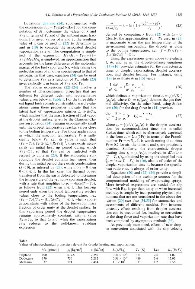
The above expressions (22)–(24) involve anumber of physicochemical properties that aredifferent for different fuels, with representativevalues given below in Table 1. For the three differ-ent liquid fuels considered, straightforward evalu-ations using these properties indicate that thelatent heat of vaporization satisfies Lv � RFT B,which implies that the mass fraction of fuel vaporat the droplet surface, given by the Clausius–Cla-peyron equation (24), remains exponentially smalluntil the droplet temperature reaches values closeto the boiling temperature. For those applicationsin which the injection temperature T I is suffi-ciently below T B, i.e., its value is such thatðT B � T IÞ=T B � ½Lv=ðRFT BÞ��1, there exists neces-sarily an initial heat up period during whichY F;S � 1, so that Y F;S can be neglected withrespect to unity in (23). If the atmosphere sur-rounding the droplet contains fuel vapor, thenduring this initial period there exists condensation(k < 0), as inferred by (23), while if Y F ¼ 0 then0 < k� 1. In this last case, the thermal powertransferred from the gas is dedicated to increasingthe temperature of the yet non-vaporizing droplet,with a rate that simplifies to _qd ¼ 4pjaðT � T dÞ,as follows from (22) when k� 1. This heat-upperiod ends when the liquid temperature reachesvalues close to the boiling temperature, i.e.,ðT B � T dÞ=T B � ½Lv=ðRFT BÞ��1 � 1, when vapori-zation starts with values of the fuel-vapor massfraction of order unity at the droplet surface. Inthis vaporizing period the droplet temperatureremains approximately constant, with a valueT d ’ T B, so that _qd ’ 0, while the vaporizationrate reduces to the well-known Spaldingexpression
Table 1Values of physicochemical properties relevant for droplet heat
MF [g/mol)] ql [kg=m3] cl [kJ/kg]
Heptane 100 679.5 2.250Dodecane 170 750 2.212Methanol 32 791 2.484
_m4pja=cp
¼ k ¼ ln 1þ cpðT � T BÞLv
� �; ð25Þ
derived by computing k from (22) with _qd ¼ 0.Clearly, the approximation T d ¼ T B used in (25)is inaccurate when the gas temperature in theenvironment surrounding the droplet is closeto the boiling temperature, i.e., ðT � T BÞ=T B �½Lv=ðRFT BÞ��1 � 1.
Using the expressions given above to evaluatef, _m, and _qd in the droplet-balance equations(14)–(16) provides estimates for the characteristictimes of droplet vaporization, droplet accelera-tion, and droplet heating. For instance, using(19) to evaluate _m in (15) yields
� 1
a3
da3
dt¼ 3
DT
a2
qql
k ¼ ktv; ð26Þ
which defines a vaporization time tv ¼ 13ða2=DT Þ
ðql=qÞ, where DT ¼ j=ðqcpÞ denotes the gas ther-mal diffusivity. On the other hand, using Stokeslaw (20) for the drag force in (14) provides
dvd
dt¼ 9
2
ma2
qqlðv� vdÞ ¼
v� vd
ta; ð27Þ
where ta ¼ 29ða2=mÞðql=qÞ is the droplet accelera-
tion (or accommodation) time, the so-calledStokes time, which can be alternatively expressedin the form ta ¼ 2tv=ð3PrÞ in terms of the Prandtlnumber Pr ¼ m=DT . It is worth noting that, sincePr ’ 0:7 for air, the times tv and ta are practicallyidentical. Similarly, the characteristic dropletheating time tq ¼ ðcl=cpÞtv involved in dT d=dt ¼ðT � T dÞ=tq, obtained by using the simplified rate_qd ¼ 4pjaðT � T dÞ in (16), also is of order of thedroplet vaporization time tv, because the specific-heat ratio cl=cp is always of order unity.
Equations (20) and (22)–(24) provide a simpli-fied description of the exchange sources for thecomputational modeling of evaporating sprays.More involved expressions are needed for slipflow with Red larger than unity or when increasedaccuracy is sought by incorporating physical phe-nomena that are not considered in the above der-ivation [20] (see also [54,55] for summaries andassessments of different models). For instance,unsteady effects resulting from droplet accelera-tion can be accounted for, leading to correctionsto the drag force and vaporization rate that havebeen computed by asymptotic methods [56].
As previously mentioned, effects of near-drop-let convection associated with the slip velocity
ing and vaporization.
Lv[kJ/kg] T B [K] LeF Lv=ðRFT BÞ0:34� 103 371 2.6 11.020:36� 103 489 3.6 15.051:1� 103 337 1.2 12.56
1560 A.L. Sanchez et al. / Proceedings of the Combustion Institute 35 (2015) 1549–1577
v� vd introduce corrections to the exchange ratesthat, surprisingly, remain moderately small as theReynolds number increases, so that (20) and (22)–(24) provide sufficient accuracy for Red � 1. Forinstance, although the expression given in (20)tends to underpredict the drag force on the drop-let as the Reynolds number increases, the under-predictions are not severe, i.e., the relative errorsare of the order of 12% for Red ¼ 1, increasingto 40% for Red ¼ 5 [57].
As a final comment, it should be mentionedthat the flow around the droplet is modified fordroplets burning individually in an oxidizingatmosphere with a surrounding flame. For drop-lets moving relative to the ambient gas with aReynolds number Red of order unity, the envelopediffusion flame around the droplet extinguisheswhen the droplet radius decreases below a criticalvalue of the order of the thickness dL of the stoi-chiometric gaseous planar deflagration. For lowervalues of the droplet radius, the fuel vapor gener-ated by the droplet will only burn in its wake, in adistributed manner. Conversely, a droplet mayburn individually with a surrounding flame whenits radius is larger than the critical extinctionvalue, that being the case observed in the spray-deflagration experiments reported in [58], whichconsider large droplets with diameters exceeding300 microns. When the droplet is surrounded bya flame, the expressions derived above forRed � 1 should be modified. For instance, inthe Spalding vaporization rate (25) the enthalpydifference cpðT � T BÞ must incorporate an aug-mented effective ambient temperature thataccounts for the presence of the flame. In the limitof infinitely fast reaction with the reasonableapproximation of unity Lewis number adoptedfor O2, the associated enthalpy increase can beshown to be equal to the ambient oxygen massfraction Y O2
times the amount of heat releasedper unit mass of oxygen consumed in the chemicalreaction [45,59]. The surrounding flame has beenshown to affect also the force acting on the droplet[52]. Modifications would also be needed in thegas-phase equations, with the burning dropletsappearing there as sources of heat and combus-tion products and as sinks for oxygen [53].
4. Spray-combustion phenomenology
The fuel vapor generated by the vaporizingdroplets mixes with the surrounding hot air,enabling ignition to occur when a favorable equiv-alence ratio is encountered. Fuel sprays can beignited using external sources such as electricsparks, torches or plasma jets, as is needed duringthe start and relight of jet engines and in the oper-ation of gasoline direct-injection engines [60,61].Forced ignition is not needed during the nor-mal steady operation of continuous-combustion
systems, such as that depicted in Fig. 2, which rep-resents the typical arrangement found in gas tur-bines or industrial furnaces [60]. The manner inwhich combustion is stabilized downstream fromthe initial vaporization region is fundamentallydependent on the injection conditions. When theexisting flow velocity is sufficiently low, combus-tion is established through partially premixedfronts that propagate along mixing layers in thenonuniform mixture created upstream by thevaporizing spray [62,63]. In many systems, how-ever, the injection velocities are much higher thanthe characteristic deflagration speed, thereby pre-cluding upstream triple-flame propagation. Inthat case, combustion stabilization must relyinstead on the autoignition of the fuel–air mix-ture, which is facilitated by the high temperatureof the surrounding gas, with ignition often occur-ring near the edge of the spray jet, where the tem-peratures are higher.
The resulting ignition dynamics depends on thedispersion of the droplets in the presence of turbu-lent motion [64]. Optimal droplet dispersion isachieved for values of the droplet Stokes time,defined in (27), of the order of the integral timescale of the large vortices in the mixing layer[17,34,65,66], under which conditions dropletsmay cross the mixing layer at vortex-braid regionsto vaporize on the other side surrounded by hotair. On the other hand, droplets with sufficientlysmall Stokes times behave as flow tracers andbecome entrained in the large-scale turbulenteddies, where they come into contact with thehigh-temperature air. The lower strain rates foundin these near-core regions facilitate ignition,whereas the larger strain rates found in the vor-tex-braid regions prevent ignition from occurringthere by limiting fuel residence times.
As suggested earlier for purely gaseous ignition[67], the unsteady unstrained flamelet -and alsothe closely related problem of the laminar coflowmixing layer- may provide an adequate represen-tation of the spray ignition dynamics occurringat the low-strain interfaces wrapped around thevortices. Numerical and asymptotic analyses ofgroup ignition of heptane and methanol spraystreams by coflowing hot air were attemptedrecently [64], with a simple one-step Arrheniusmodel adopted for the chemistry description.The two main controlling parameters were seento be the liquid mass-loading ratio a of the sprayand the ratio of the droplet vaporization time tv tothe characteristic chemical time for ignition tch,evaluated at the air-side temperature, bothassumed to be of order unity in the integrations.The solution was seen to depend strongly on thethermochemical properties of the selected fuel.Thus, because of its smaller latent heat of vapori-zation Lv, heptane droplets vaporize faster thanmethanol droplets. As a result, as the mixing layerdevelops, heptane vapor becomes available for
A.L. Sanchez et al. / Proceedings of the Combustion Institute 35 (2015) 1549–1577 1561
reaction earlier than methanol vapor, therebyleading to smaller ignition distances, a result inagreement with the ignition trends observed inprevious numerical computations of ignition timesin uniform spray mixtures [68]. Besides, the igni-tion of heptane is facilitated by its chemical heatrelease being more than twice that of methanol,resulting in a larger temperature increase per unitmass of fuel burnt that facilitates the self-accelera-tion of the chemical reaction rate, enabling a ther-mal runaway to take place. By way of contrast,the ignition of methanol proceeds gradually, inthe form of a lean premixed flame that propagatesslowly across the mixing layer from the hot air side.As shown in [64], the morphology of the ignitionregion is very sensitive to the specific values of theparameters selected. For instance, when air isemployed as spray carrier, two-flame structures[69–73] are seen to emerge when the thermochemi-cal properties of heptane are considered, but theyare not observed for methanol.
As mentioned earlier, for all liquid fuels themass of air needed to burn the unit mass of fuel,S, is a very large quantity (i.e., S ’ 15:2 for hep-tane). As a result, in many applications, the par-tially premixed front originating at the ignitionkernel burns completely the air that has beenentrained upstream, while consuming only a lim-ited fraction of the fuel available in the jet spray.The remaining gaseous fuel and accompanyingfuel droplets burn downstream, in a diffusionflame that envelops the oxygen-starved spray jet.The resulting group-combustion configurationwas envisioned as the predominant combustionregime in early theoretical analyses of droplet-cloud combustion, to be discussed in Section 6.The extent to which the partially premixed regioncontributes to the overall combustion processdepends on the specific configuration and mayalso change depending on the operating condi-tions, as observed in direct numerical simulations[73], which also reinforce the qualitative descrip-tion given above.
Figure 2 depicts an external diffusion-flameconfiguration, often encountered in applications,in which the diffusion flame stands off the dropletcloud, burning the ambient oxygen with the fuelthat originates from the vaporizing droplets. Inmany applications, the gas-phase chemical reac-tions are fast, in that the characteristic time forfuel oxidation is much shorter than both the char-acteristic fluid-mechanical time and the droplet-vaporization time. Under those conditions, theflame appears as a sheet, Rf , separating an inter-nal oxygen-free region XF from an external regionXO where no gaseous fuel is present in significantamounts. The associated Burke-Schumann limitof infinitely fast combustion will be discussed inSection 5.
For the high-Reynolds-number flows typicallyencountered in liquid-fueled burners, the diffusion
flame is embedded in thin mixing layers boundingthe spray-carrier stream. These mixing layers aredistorted and strained by the turbulent flow. Acanonical problem that helps to investigate effectsof strain on spray diffusion flames is the counter-flow configuration [74], which will be addressedin Section 7. Sufficiently large values of the strainrate may lead to flame extinction [75]. When thisoccurs, the flame surface develops an incipient holewith a bounding edge flame that propagates alongthe mixing layer. The dynamics of these edgeflames under the action of the external strain deter-mines whether the flame hole reheals, through areignition triple flame, or whether the extinctionhole continues to increase, as the edge flame fur-ther retreats. While there exists substantial knowl-edge of many aspects of edge flames and tripleflames in gaseous combustion [76,77], the associ-ated spray problem has only been consideredrecently [78] and more work is needed to both clar-ify the structure of spray edge flames and quantifythe dependences of their propagation velocity.
Large droplets with sufficient inertia may crossthe mixing layers and move into the oxidizerstream, where they can possibly burn or vaporizeindividually or in small groups if favorable condi-tions are found. In principle, a closed diffusionflame may appear surrounding each individualdroplet if their radius is large enough and favorableconditions for ignition are found as the dropletenters the oxidizer region [79]. The droplets in mostpractical combustion applications are however toosmall to sustain a flame in their vicinity. Therefore,as indicated in Fig. 2, many of the droplets thatcross the spray diffusion flame can be expected tovaporize in XO without a surrounding flame, gener-ating fuel vapor that reacts with the existing oxygenin a distributed manner. Although the contributionof this distributed reaction to the total amount ofheat released in the combustor can be expected tobe negligible, these finite-rate effects are of utmostimportance, since partial oxidation of the fuelvapor generated by the crossing droplets, especiallyin the cold regions found near the combustor walls,results in augmented emissions of CO and unburnthydrocarbons. Extensions of the Burke-Schumannformulation using reduced mechanisms to describefinite-rate effects leading to pollutant emissions willbe presented in Section 5.
Before closing this overview, it is worthdescribing briefly the transient combustion phe-nomenology associated with the combustion cyclein diesel engines. Diesel–fuel injection into thecylinder begins shortly before top dead center.The spray starts to vaporize immediately as itmixes with the compressed hot air, creating anonuniform mixture of fuel vapor and air, whosetemperature continues to increase as a result ofthe homogeneous compression process that isoccurring simultaneously, thereby enhancing theincipient chemical reaction. Autoignition occurs
1562 A.L. Sanchez et al. / Proceedings of the Combustion Institute 35 (2015) 1549–1577
simultaneously at several near-stoichiometric hotspots in the bulk of the spray jet, where the mostfavorable conditions are met, leading to the for-mation of ignition fronts that sweep through thereactive mixture with a velocity of a few tensmeters per second. This rapid process is accompa-nied by a significant increase of temperature andpressure in the cylinder that further acceleratesthe chemical reaction. The magnitude of thesepressure and temperature increments depends onthe fraction of the liquid fuel that was vaporizedprior to ignition. As they propagate through thespray jet, the ignition fronts deplete the oxygenfound in fuel-rich regions and the fuel vaporfound in fuel-lean regions, leaving a diffusionflame at the instantaneous stoichiometric surface.As a result, an internal group combustion regimeemerges following ignition, with the diffusionflame located within the spray, separating an inneroxygen-free region from an outer region free fromgaseous fuel. In the subsequent evolution, thedroplets found outside may burn individually ormay vaporize, generating fuel vapor that mixesand reacts with the available air. As mentionedin Section 6, analyses of droplet-cloud combus-tion can be instrumental in investigating all thesediesel-engine-combustion phenomena.
5. The Burke-Schumann limit of infinitely-fastreaction in non-premixed spray flames
In many liquid-fuel combustors the burning ofthe jet spray involves a thin nonpremixed flame sur-rounding the droplet cloud. The rates of the gas-phase chemical reactions, which control the igni-tion distance and determine the structure of the par-tially premixed region, can be considered asinfinitely fast for the diffusion flame that developsdownstream; because the characteristic time forfuel oxidation is much shorter than both the charac-teristic fluid-mechanical time and droplet-vapori-zation times. Under those conditions, the non-premixed spray flame is diffusion-controlled andcan be consequently described in the first approxi-mation by considering the limit of infinitely fastchemistry, to be addressed now following [80].
5.1. The limit of infinitely fast reaction
For simplicity, the presentation will considerthat the chemical reaction between the oxygen ofthe air and the fuel vapor occurs according tothe global irreversible step
Fþ sO2 ! sCO2CO2 þ sH2OH2Oþ q; ð28Þ
where s, sCO2, and sH2O are the mass of oxygen
consumed and the mass of carbon dioxide andwater vapor produced per unit mass of fuel burnt,so that 1þ s ¼ sCO2
þ sH2O, and q is the corre-sponding amount of heat released. This overall
reaction is an appropriate representation of theunderlying chemistry when the concentrations ofthe intermediate reactive species are small com-pared with those of the main species appearingin (28), as it is typically the case in many combus-tion processes. Note that these intermediates,although appearing in small concentrations, deter-mine the effective rate of the overall fuel-oxidationreaction (28), resulting from the interplay of ele-mentary chemical reactions occurring at molecu-lar level. This rate is necessary for describingpremixed and partially premixed combustion,but is not essential for diffusion-controlled flames,as long as the strain conditions place the systemaway from extinction.
When the simplified description (28) is usedto represent the overall combustion process,the conservation equations for reactants (9)reduce to
@
@tqY Fð Þ þ r � qvY Fð Þ � r � qDT
LeF
rY F
� �¼ �xF þ
XNc
j¼1
nj _mj; ð29Þ
and
@
@tqbY O2
þr � qvbY O2
�r � qDTrbY O2
¼ �SxF: ð30Þ
where the oxygen mass fraction has been scaledwith its value in the air stream to give the nor-malized variable bY O2
¼ Y O2=Y O2A
. Correspond-ingly, S ¼ s=Y O2A
denotes the mass of airneeded to burn the unit mass of fuel, a moder-ately large quantity, as previously mentioned.In the formulation, xF represents the mass offuel consumed per unit volume per unit time,which is related by xF ¼ � _wF to the productionrate used above in (9). In writing Fick’s law forthe diffusion velocities, a unity Lewis number isassumed for O2, whereas a general non-unityLewis number is used for the fuel, with represen-tative values given in Table 1.
To illustrate the Burke-Schumann limit ofinfinitely fast reaction rate, it is convenient toconsider as an approximation the Arrheniusexpression
xF ¼ qBbY O2Y F exp½�Ea=ðRoT Þ� ð31Þ
for the reaction rate, including a frequency factorB and an activation energy Ea, defining a charac-teristic temperature-dependent chemical time forfuel oxidation
tch ¼ B�1 exp½Ea=ðRoT Þ�: ð32ÞEquation (31) can be used to express the reactionrates appearing in the conservation equations (29)and (30), giving for instance
A.L. Sanchez et al. / Proceedings of the Combustion Institute 35 (2015) 1549–1577 1563
1
qLðY FÞ|fflfflfflffl{zfflfflfflffl}Y F=tv
¼ �BbY O2Y F exp½�Ea=ðRoT Þ�|fflfflfflfflfflfflfflfflfflfflfflfflfflfflfflfflfflfflfflfflffl{zfflfflfflfflfflfflfflfflfflfflfflfflfflfflfflfflfflfflfflfflffl}bY O2
Y F=tch
þ n _m=q|fflffl{zfflffl}1=tv
ð33Þfor the fuel balance, where LðY FÞ represents thetransport operator appearing on the left-handside of (29). For the discussion, the anticipatedorders of magnitude of the different competingphenomena have been indicated below eachterm, with the rates of accumulation and trans-port evaluated by assuming that the dominantfluid mechanical times are of the order of thedroplet vaporization time and the source termevaluated for a � 1.
Because of the large activation energy presentin combustion reactions, the value of tch given in(32) depends strongly on the local temperature,achieving its smallest value in the reaction region,where the temperature is of the order of the stoi-chiometric adiabatic flame temperature T f . TheBurke-Schumann limit arises in reactive sprayswhen the associated fuel oxidation time is muchsmaller than the characteristic vaporization andtransport times, of order tv, a condition often sat-isfied in practical burners whenever complete fuelconsumption is to be achieved in the primaryhigh-temperature combustion region. Accordingto the above order-of-magnitude analysis, in thislimit tch � tv of infinitely large Damkohler num-bers the conservation equations for chemical spe-cies lead to the conditionbY O2
Y F ¼ 0; ð34Þindicating that the fuel and the oxidizer cannotcoexist in the first approximation, except withina very thin reaction layer, to be described at lead-ing order in the limit tv=tch !1 as an infinitesi-mally thin sheet, denoted by Rf in Fig. 2. Thisflame sheet separates a region XF, wherebY O2¼ 0, from a region XO, where Y F ¼ 0,
whereas at the flame sheet both reactant massfractions are simultaneously zero. In the solutionthat appears, the droplets lying in the oxygen-freeregion XF vaporize without chemical reaction,generating the fuel vapor that burns at the flamewith the oxygen found in XO.
5.2. Gas-phase coupling functions for reactivesprays
To remove the singular character of the solu-tion associated with the limit tv=tch !1, whenthe reaction terms in the conservation equationsbecome Dirac delta distributions along Rf , we fol-low the standard procedure indicated by Shvaband Zeldovich [81,82], consisting in eliminatingthe chemical reaction terms appearing in the con-servation equations by appropriate linear combi-nations. The procedure is straightforward when
the Lewis numbers of both reactants are unity,but it is somewhat more complicated when prefer-ential diffusion is considered, because the linearcombinations may result in coupling functionsthat are different for the diffusion terms and forthe convective and accumulation terms [83,84].For instance, when a non-unity Lewis number ispresent in (29), elimination of the chemical reac-tion by subtracting (30) from (29) times S yields[80]
@
@tqZð Þþr � qvZð Þ � S=LeF þ 1
S þ 1r � qDTreZ
¼XNc
j¼1
nj _mj; ð35Þ
involving two different mixture-fractionvariables
Z ¼ SY F � bY O2þ 1
S þ 1and
eZ ¼ SY F=LeF � bY O2þ 1
S=LeF þ 1:
ð36Þ
A similar procedure must be utilized to eliminatethe heat-release rate by chemical reaction�PNs
i¼1hoi _wi ¼ qxF from the energy equation.
Since the Lewis number of oxygen is assumed tobe unity, it is convenient to use (30) to derivethe corresponding chemistry-free coupling func-tion. The derivation is further facilitated byneglecting variations of the specific heat at con-stant pressure. Under those approximations, anappropriate linear combination of (12) and (30)with use made of (8) provides
@
@tqHð Þ þ r � qvHð Þ � r � ðqDTrHÞ
¼ �r � qR
�XNc
j¼1
nj _mj q=S þ Lv þ cpðT A � T jdÞ
� �þ _qj
d
� þ dpo
dtð37Þ
for the excess-enthalpy variable H ¼ cpðT � T AÞþðbY O2
� 1Þq=S, where T A represents the tempera-ture of the primary air-feed stream.
In the description of the limit of infinitely largeDamkohler numbers, the three conservation equa-tions for the reactants and energy are replacedwith the chemistry-free equations (35) and (37),together with the condition (34) of non coexis-tence of the reactants. The flame is located whereboth the vapor fuel Y F and the oxygen bY O2
aresimultaneously zero, corresponding to values ofthe mixture fraction Z ¼ Zst ¼ 1=ð1þ SÞ andeZ ¼ eZ st ¼ 1=ð1þ S=LeFÞ. For Z P Zst we findbY O2¼ 0, so that
1564 A.L. Sanchez et al. / Proceedings of the Combustion Institute 35 (2015) 1549–1577
Y F ¼Z � Zst
1� Zst¼eZ � eZ st
1� eZ st
and
cpðT � T AÞ ¼ H þ qS;
ð38Þ
whereas Y F ¼ 0 for Z 6 Zst, giving
bY O2¼ 1� Z
Zst¼ 1�
eZeZ st
and
cpðT � T AÞ ¼ H þ qS
ZZst:
ð39Þ
These relationships link the values of Z, eZ , and Hand provide the mass fractions of reactants andthe temperature in terms of the coupling functionseverywhere in the flow field. If needed, source-freeconservation equations that determine the prod-uct concentrations can be obtained from linearcombinations accounting for non-unity Lewisnumbers of CO2 and H2O [80].
5.3. Distributed air-side fuel oxidation
The formulation given above allows for thepresence of droplets in XO. These droplets maybe initially in XF and cross the flame at a giveninstant as a result of dispersion by turbulenteddies, or they may be already in XO when the dif-fusion flame forms, as occurs in diesel engineswith the droplets located in the outer part of thedroplet cloud at ignition. When this arises, indi-vidual combustion of large droplets is then possi-ble, provided that the droplets are sufficientlyseparated for the inter-droplet environment tohost individual droplet flames and their Reynoldsnumber Red does not exceed a critical extinctionvalue. The Burke-Schumann formulation remainsvalid in the presence of droplets burning individu-ally in XO, provided that the expression for thevaporization rate _m is modified for the burningdroplets, as indicated above at the end ofSection 3.2.
It can be expected, however, that for the condi-tions found in many practical liquid-fueled burn-ers, with typical droplet radii on the order of afew tens of microns, the droplets cannot burnindividually with a surrounding flame becausethe fuel-oxidation time tch, although much smallerthan the droplet vaporization time, is much largerthan the characteristic diffusion time around thedroplet. If tch is also much larger than the charac-teristic interdroplet diffusion time l2
d=DT , so thatthe inequalities l2
d=DT � tch � tv hold, the fuelgenerated by droplets vaporizing in XO is homoge-neously consumed in a distributed reaction occur-ring in the gas phase between droplets that can bedescribed with the multi-continua formulation.According to the anticipated orders of magnitudedisplayed in (33), the fuel-vapor mass fraction in
XO, of order Y F � tch=tv � 1, can be determinedwith negligible transport effects. Equating thefuel-consumption rate by chemical reaction andthe fuel-generation rate by droplet vaporizationyields in the first approximation, from (25) and(31),
Y F ¼4pB
aDT nbY O2
exp½Ea=ðRoT Þ�
� ln 1þ cpðT � T BÞLv
� �ð40Þ
as an explicit expression for the distribution of thefuel mass fraction, where the values of a, DT , n,bY O2
, and T are to be evaluated from the leading-order Burke-Schumann solution. The accuracyof the above prediction is subject to the conditionthat the chemistry remains sufficiently fast for thetransport rate to be negligible in (33). Because ofthe temperature dependence of the reaction rate,in regions of lower temperature the chemical reac-tion becomes slower. The associated fuel-con-sumption time (32) becomes comparable to thevaporization time when the temperature decreasesto values of the order of a critical crossover tem-perature, T cc, such that
B�1 expEa
RoT cc
� �¼ tv: ð41Þ
In regions away from the flame where T � T cc, thelocal Damkohler number
tv
tch¼ exp
Ea
RoT cc� Ea
RoT
� �; ð42Þ
defined with use made of (32) and (41), becomesof order unity, so that transport effects enter tomodify the analytic prediction (40), with largercorrections expected to appear at increasing dis-tances from the flame. If the nondimensional acti-vation energy Ea=ðRoT ccÞ is large, then (42)indicates that fuel consumption freezes as soonas the temperature falls below T cc (i.e., the localDamkohler number becomes exponentiallysmall), whereas in regions where T > T cc fuel con-sumption is very rapid, giving the quasi-steadydistribution (40) with exponentially small valuesof Y F. For T < T cc, the fuel mass fraction is deter-mined by a balance between transport and vapor-ization. Consideration of fuel transport in thesecold regions would be needed in particular todetermine emissions of unburnt hydrocarbons inliquid-fueled combustors. The computation ofthe small fuel-mass fraction as a higher-order cor-rection to the Burke-Schumann solution wouldrequire integration of (29) in the region Z < Zst.The resulting problem is linear in Y F, because allof the remaining variables appearing in (29),including in particular bY O2
and T , are to be eval-uated from the leading-order solution.
A.L. Sanchez et al. / Proceedings of the Combustion Institute 35 (2015) 1549–1577 1565
5.4. Quantification of CO emissions
The previous finite-rate results can be extendedto account for more realistic fuel-oxidation descrip-tions. Although the detailed chemistry of liquidfuels typically involves a few thousand elementaryreactions between a few hundred reactive species,flame studies have demonstrated that most of thechemical intermediates are in steady state, so thatreduced chemical-kinetic descriptions with just afew overall steps provide sufficient accuracy[85,86]. For most purposes, combustion of a givenhydrocarbon CMHN can be described by introduc-ing steady-state approximations for all but threechemical intermediates, namely, CO, H2, and a rad-ical representing the hydrogen–oxygen radical pool.For the lean conditions found in XO, hydroxyl rad-icals are more abundant than H atoms [87], so it isbest to develop the chemistry reduction with CO,H2, and OH as species out of steady state, leadingto the four overall reactions
CMHN þROH!I MCOþ ðR�MÞH2O
þ ½Mþ ðN �RÞ=2�H2;
H2 þO2 �II
2OH;
2OHþH2!III
H2O;
COþH2O �IV
CO2 þH2; ð43Þ
representing fuel consumption, chain branching,chain recombination, and CO oxidation, with Rdenoting the number of radicals consumed perfuel molecule consumed. The value of the integerR, 1 6 R 6 N , depends on the details of thefuel-radical steady states. The correspondingoverall rates (mols per unit volume per unit time)can be expressed as
wI ¼ k6f CFCOH þ k7f CFCH
wII ¼ k1f CO2CH � k1bCOCOH
wIII ¼ k4f CMCO2CH
wIV ¼ k5f CCOCOH � k5bCCO2CH ð44Þ
in terms of those of elementary reactions H + O2
�1
O + OH, H + O2 +M!4fHO2 +M, CO + OH
�5
CO2 + H, CMHN + OH !6fCMHN�1 + H2O,
and CMHN + H !7fCMHN�1 + H2, with kjf and
kjb denoting the forward and backward reaction-rate constants for each reaction j.
The concentrations of H and O, needed in eval-uating the overall reaction rates given in (44), canbe obtained by assuming partial equilibrium of the
fast shuffle reactions H2 + OH �2
H2O + H and
OH + OH �3
H2O + O to give CH ¼ K2CH2COH=
CH2O and CO ¼ K3C2OH=CH2O, where K2 ¼ k2f =k2b
and K3 ¼ k3f =k3b are equilibrium constants. Forthis reduced description, conservation equations
can be written for the fuel and for the differentintermediates according to
LðY FÞ ¼ �MFwI þ n _m;
LðY COÞ ¼ MCOðMwI � wIVÞ;
LðY H2Þ ¼ MH2
f½Mþ ðN �RÞ=2�wI � wII � wIII þ wIVg;
LðY OHÞ ¼ MOHð�RwI þ 2wII � 2wIIIÞ:
As in (33), the symbol L is used here to representthe transport differential operator for each chem-ical species.
In near-flame zones of XO where the tempera-ture is of the order of adiabatic flame temperatureT f , the chemical times associated with the fouroverall reactions are sufficiently small for the con-dition tch � tv to hold, so that the transport termscan be neglected in the first approximation in theabove equations, reducing the computation of theconcentrations of CMHN , CO, H2, and OH tothe solution of the reduced fuel conservationequation
MFwI ¼ n _m; ð45Þindicating that fuel produced by droplet vaporiza-tion is immediately consumed by chemicalreaction, along with the three steady-state expres-sions for the intermediates, which can be solved togive
CH2¼ k5f
K2ðc5b þ AFÞk4f CM
CH2 OCCO
CO2
; ð46Þ
COH ¼k1f
k4f CM
� BF
� �1=2 k5f
K3ðc5b þ AFÞk1b
� �1=2
C1=2H2OC1=2
CO; ð47Þ
in terms of the reaction-rate ratioc5b ¼ k5bCCO2
=ðk4f CMCO2Þ and the fuel-specific
constants
AF ¼M
MþN � 2R and
BF ¼4MþN
4MþN � 2R :ð48Þ
Note that, according to (47), this steady-state description gives a zero OH concentrationas the temperature decreases to a crossover valueT cc, defined in this case by the conditionk1f ¼ BFk4f CM. For T < T cc, the expression (47)should be replaced by the condition COH ¼ 0.The corresponding CO-oxidation rate,
wIV ¼AF
ðk1bK3Þ1=2
k5b
c5b þ AF
� �3=2 k1f
k4f CM
� BF
� �1=2
C1=2H2OC3=2
CO;
ð49Þ
obtained from (44) with use made of (47), alsoincludes the crossover factor, and therefore van-ishes at T ¼ T cc.
The expression (49) can be used to evaluateexplicitly the CO-oxidation rate appearing in theconservation equation for CO,
1566 A.L. Sanchez et al. / Proceedings of the Combustion Institute 35 (2015) 1549–1577
@
@tqY COð Þ þ r � qvY COð Þ � r � qDT
LeCO
rY CO
� �¼MMCO
MF
n _m�MCOwIV; ð50Þ
written here with use made of (45) to express wI.Since the activation energy of reaction 1f is mod-erately large, at temperatures above crossover therate wIV is fast, and the associated CO-oxidationtime is much smaller than the characteristicfluid-mechanical time. In these hot regions, thetransport terms in (50) can be neglected in the firstapproximation, giving the balanceMn _m ¼ MFwIV
for the CO concentration in this region of largeDamkohler numbers. The equation can be solvedfor CCO to give
CCO ¼c5b þ AF
k5b
k1bK3
M2FCH2O
� �1=3 k1f
k4f CM
� BF
� ��1=3
� ðMþN � 2RÞn _m½ �2=3:
ð51Þ
This transportless expression fails however as thetemperature approaches crossover, because therate (49) decreases to zero, with the result that(51) incorrectly predicts an infinite CO concentra-tion at T ¼ T cc. Inclusion of CO transport readilyavoids this singularity, imposes a limitY CO � ðMMCOn _mtvÞ=ðqMFÞ on CCO in terms ofthe local value of n _m (small in the region wherefreezing occurs), and enables the correct descrip-tion of CO to be obtained for T < T cc, wherewIV ¼ 0 and the CO generated by partial oxida-tion of the vaporized fuel is transported awaywithout significant oxidation to CO2. In integrat-ing (50) in XO one may use the concentrations ofO2, H2O, CO2, temperature, number of dropletsper unit volume n, and radius a correspondingto the leading-order Burke-Schumann solutionto evaluate the vaporization rate n _m and theCO-oxidation rate from (25) and (49). Clearly,similar ideas could be employed to generate anequation for describing the generation of otherpollutants, notably NO.
6. Vaporization and combustion of fuel-sprayclouds
The description given in Section 2 illustratesthe importance of group effects, with the meangas-phase environment generated collectively bythe droplets determining the overall vaporizationand combustion dynamics of the spray. Elemen-tary problems involving a limited number ofcompeting phenomena serve to illustrate theinterplay of the different physicochemical pro-cesses. Regimes of group vaporization and com-
bustion of sprays have been defined byconsidering quasisteady solutions to uniform,spherically symmetric, quiescent fuel-dropletclouds [88–94]. Under appropriate simplifyingassumptions, a single dimensionless parameter,called the group combustion number [88], hasbeen reasoned to control the energy and masstransfer between the droplet cloud and the sur-rounding atmosphere. Since this number iswidely used in applications, it is of interest todiscuss its connection with the spray parametersand characteristic times identified above byaddressing the problem of transient vaporizationof a monodisperse droplet cloud in a hot airenvironment at constant pressure.
6.1. The continuum, homogenized description ofdroplet-cloud vaporization
Let us consider the temporal evolution of aspherical cloud of radius Ro containing air andN o uniformly distributed droplets of radius ao
and initial temperature T I . An unbounded atmo-sphere of hot air with temperature T A > T I anddensity qA surrounds the cloud. The initial numberof droplets per unit volume in the cloud,no ¼ N o=½ð4=3ÞpR3
o�, defines the interdroplet dis-tance ld ¼ n�1=3
o , which is assumed to be in therange Ro � ld � ao, so that the condition (7) is sat-isfied. The droplet number density together withthe droplet radius and the gas density defines theliquid mass-loading ratio, a ¼ ð4p=3Þa3
onoql=qA;when a � 1 we can expect two-way couplingbetween the phases. The cloud evolution is mainlydetermined by the competition of droplet vapori-zation with heat conduction across the dropletcloud. The rate of the former is measured by thecharacteristic droplet vaporization time tv, givenin (26) as a function of the initial values of thedroplet radius ao and air density and thermal diffu-sivity qA and DT A , whereas the heat conductiontime based on the cloud radius tc ¼ R2
o=DT A charac-terizes gas-phase heat conduction from thesurrounding atmosphere. Another significantparameter is T A=T B.
The description of the problem delineatedabove requires integration of (8), (9), and (12)for the gas phase together with (13)–(17) for theliquid phase, supplemented with the equation ofstate and with additional equations for the dropletsource terms f, _m, and _qd . Since the heat needed toheat up and vaporize the equilibrium dropletcloud must come from the surrounding hot air,it is appropriate to use the heat conduction timetc to scale the problem. Introducing the dimen-sionless variables t ¼ t=tc, r ¼ r=Ro, v ¼ vr=ðDT A=RoÞ, bT ¼ T=T A, q ¼ q=qA, n ¼ n=no, a ¼a=ao, bT d ¼ T d=T A, and vd ¼ vdr=ðDT A=RoÞ,reduces the conservation equations for the gasphase to
A.L. Sanchez et al. / Proceedings of the Combustion Institute 35 (2015) 1549–1577 1567
@q
@ tþ 1
r2
@
@rr2qv� �
¼ atc
tvnabT rk; ð52Þ
@qY F
@ tþ 1
r2
@
@rr2qvY F
� �� 1
r2
@
@rr2bT r
LeF
@Y F
@r
!¼ a
tc
tvnabT rk; ð53Þ
@qbT@ tþ 1
r2
@
@rr2qvbT
� 1
r2
@
@rr2bT r @bT
@r
!
¼ �atc
tvnabT r ðbT � bT dÞ
kek � 1
� bT dk
� �; ð54Þ
to be supplemented with qbT ¼½1�ð1�MA=MFÞY F��1, where MA=MF denotes the air-to-fuelmolecular-mass ratio. A simple power law withexponent r¼0:7 has been adopted for the temper-ature dependence of the transport coefficients.Radiative heat transfer has been neglected inwriting (54), along with changes in specific heat.The source terms in (52)–(54) are proportionalto n, which satisfies the conservation law
@n@ tþ 1
r2
@
@rr2nvd
� �¼ 0; ð55Þ
involving the droplet velocity vd . This parabolicsystem of equations must be complemented withthe simultaneous Lagrangian description of thevariation of the droplet properties a, bT d , vd , givenby
da3
dt¼ � tc
tvabT rk; ð56Þ
a3 dbT d
dt¼ tc
tv
cp
clabT r ðbT � bT dÞ
kek � 1
� Lv
cpT Ak
� �;ð57Þ
a3 dvd
dt¼ 3Pr
2
tc
tvabT rðv� vdÞ; ð58Þ
along the droplet paths rdðn; tÞ, given by the solu-tion of drd=dt ¼ vd in terms of its initial radiallocation rd ¼ n. The source terms in the aboveequations, which are proportional to _m and _qd ,have been written using (19) and (22) in terms ofk, which is determined using (23), i.e.,k ¼ Le�1
F ln½ð1� Y FÞ=ð1� Y F;SÞ�, as a function ofY F and Y Fs . The latter is given by the Clausius–Clapeyron relation (24) in terms of bT d , withMF=Ms ¼ Y Fs þ ð1� Y FsÞMF=MA, thereby com-pleting the formulation.
Different possible sets of initial conditions canbe considered [94]. For example, one may assumethat the droplets are suddenly placed in the unper-turbed hot-air environment at the start of the inte-gration, with the uniform gas temperature T A
everywhere at t ¼ 0. Perhaps a more realistic ini-tial condition, especially in connection with con-trolled experiments in which the spray is formedupstream from the injection section, follows fromassuming that the spray is initially in equilibrium,so that k ¼ 0 and T ¼ T d in the cloud, as is
required for the right-hand side terms of (52)–(54), (56), and (57) to vanish. The associatedinitial conditions for (52)–(55) are q� qI ¼ bT�bT I ¼ Y F � Y FI ¼ n� 1 ¼ 0 for r 6 1 and by
q� 1 ¼ bT � 1 ¼ Y F ¼ n ¼ 0 for r > 1, where qI
is the interdroplet gas density associated withbT ¼ bT I and Y FI , with Y FI determined from evalu-ating (24) at T d ¼ T I . Correspondingly, the inte-gration of (56)–(58) is initiated with a� 1 ¼vd ¼ bT d � bT I ¼ 0. Boundary conditions fort > 0, needed to integrate (52)–(54) are given by
v ¼ @bT =@r ¼ @Y F=@r ¼ 0 at r ¼ 0 and bT � 1 ¼Y F ¼ 0 as r!1.
Many of the early numerical investigations ofspherical droplet-cloud vaporization [88–94]neglected the motion of the droplets induced bythe gas expansion along with the resulting nonuni-formities in n, both having in general a nonnegli-gible effect on the solution, as shown in [95,96].These effects are effectively handled in the multi-continua formulation outlined above. It is worthmentioning that, although the droplets in the inte-rior of the cloud may conceivably accelerate toovertake those located farther outside, with theresult that droplets originating at different n endup occupying the same radial location, such over-taking events were not observed in computations.If they occur, i.e., for initial conditions or para-metric values different from those considered here,the associated duplicity should be taken intoaccount when evaluating the droplet propertiesat a given location (e.g., by creating a new dropletclass containing the droplets that have been over-taken, in a similar procedure as that employed inSection 7 for counterflow flames).
For numerical studies of vaporization andcombustion of spray clouds in constant-volumeor variable-volume chambers [95], of interest fordiesel-engine applications, the term dpo=dt mustbe retained in writing (54) from (12), while theeffect of the finite size of the combustion chambercould be effectively incorporated by introducing amoving or stagnant external wall at a finite radiusr ¼ Re=Ro. Since near stoichiometric conditionsare of interest in diesel-engine combustion, valuesof Re=Ro � ðaSÞ1=3 should be considered in inte-grations. Such formulations could be employedto investigate autoignition by compression, pro-viding the distributions of temperature and com-position encountered immediately before ignition[97]. They would also be useful for studying thesubsequent evolution of the diffusion flame gener-ated upon ignition, which could be described inthe limit of infinitely fast combustion.
6.2. Parameters controlling droplet-cloudvaporization
The solution depends on two fundamentalindependent parameters, the initial mass-loading
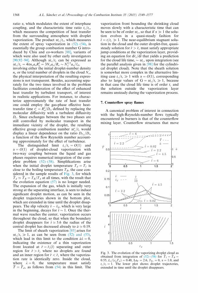
Fig. 3. The evolution of the vaporizing droplet cloud asobtained from integration of (52)–(58) for bT I ¼ bT B ¼0:55, Lv=ðcpT AÞ ¼ 0:48, LeF ¼ 2:6, Y FI ¼ 0, a ¼ 1:0, andtc=tv ¼ 1. The lower plot shows droplet trajectories,extended in time until the droplet disappears.
1568 A.L. Sanchez et al. / Proceedings of the Combustion Institute 35 (2015) 1549–1577
ratio a, which modulates the extent of interphasecoupling, and the characteristic time ratio tc=tv,which measures the competition of heat transferfrom the surrounding atmosphere with dropletvaporization. The product atc=tv, which measuresthe extent of spray vaporization in (52)–(54), isessentially the group combustion number G intro-duced by Chiu and co-workers [88], variants ofwhich were also used by other early investigators[90,92–94]. Although atc=tv can be expressed asatc=tv ¼ 4pnoaoR2
o ¼ 3N oao=Ro � N 2=3o ao=ld ,
involving either the initial droplet-number densityno or the total number of droplets in the cloud No,the physical interpretation of the resulting expres-sions is not transparent. Besides, accounting sepa-rately for the two times involved in the problemfacilitates consideration of the effect of enhancedheat transfer by turbulent transport, of interestin realistic applications. For instance, to charac-terize approximately the rate of heat transferone could employ the gas-phase effective heat-transfer time tc ¼ R2
o=Dt, defined by replacing themolecular diffusivity with a turbulent diffusivityDt. Since exchanges between the two phases arestill controlled by molecular transport in theimmediate vicinity of the droplet, the resultingeffective group combustion number atc=tv woulddisplay a linear dependence on the ratio DT A=Dt,a function of the flow Reynolds number account-ing approximately for the effect of turbulence.
The distinguished limit tc=tv ¼ Oð1Þ anda ¼ Oð1Þ of droplet-cloud vaporization withtwo-way coupling between the liquid and gasphases requires numerical integration of the com-plete problem (52)–(58). Simplifications arisewhen the initial droplet temperature T d ¼ T I isclose to the boiling temperature T B, the case con-sidered in the sample results of Fig. 3, for whichbT d ’ bT B ¼ T B=T A at all times, with the result thatthe evolution equation (57) is no longer needed.The expansion of the gas, which is initially verystrong at the separating interface, is seen to inducesignificant droplet motion, as can be seen in thedroplet trajectories shown in the bottom plot,which are extended in time until the droplet disap-pears. The slip velocity v� vd , which is very largein the beginning, decays for t � 1. Once the ther-mal wave reaches the center, vaporization occursthroughout the cloud, so that when the boundarydroplet disappears for t ’ 5:6 the radius of thecentral droplet has decreased already to a ’ 0:19.
The limit of sheath vaporization [93] arises foratc=tv � 1, as can be seen from (52) and (53),which lead in this limit to the condition ak ¼ 0,indicating the existence of a thin vaporizationfront located at r ¼ rsðtÞ separating and outerregion for r > rs where no droplets are foundand an inner region for r < rs where the vaporiza-tion rate is identically zero. Inside the cloud,where k ¼ 0, the temperature must satisfybT ¼ bT d , as follows from (54) in this limit. The
vaporization front bounding the shrinking cloudmoves slowly with a characteristic time that canbe seen to be of order atc, so that if a� 1 the solu-tion evolves in a quasi-steady fashion fort ¼ t=tc � 1. The near-equilibrium stagnant solu-tion in the cloud and the outer droplet-free, quasi-steady solution for r > rs must satisfy appropriatejump conditions at the vaporization layer, provid-ing an equation for drs=dt that yields a predictionfor the cloud life time, � atc, upon integration (seethe parallel analysis given in [98] for the cylindri-cal droplet cloud). Note that the sheath solutionis somewhat more complex in the alternative lim-iting case tc=tv � 1 with a ¼ Oð1Þ, correspondingalso to large values of G ¼ atc=tv � 1, becausein that case the cloud life time is of order tc andthe solution outside the vaporization layerremains unsteady during the vaporization process.
7. Counterflow spray flames
A canonical problem of interest in connectionwith the high-Reynolds-number flows typicallyencountered in burners is that of the counterflowmixing layer. Counterflow structures that move
A.L. Sanchez et al. / Proceedings of the Combustion Institute 35 (2015) 1549–1577 1569
with the mean velocity can be abstracted from theinterface dynamics of shear and mixing layers [99].Similarly, local counterflow configurations emergein typical combustion chambers around the stag-nation point that forms near the injector exit as aresult of vortex breakdown of the swirling air-feedstream [100]. Counterflow configurations havebeen widely employed in laboratory experimentsfor studying reacting and non-reacting spray flows[79,101–106] as well as in numerical simulations toaddress the effects of strain on spray flames[75,104,107–116]. The typical experimental arrange-ment involves two opposing nozzles of radius Rlocated at a distance h. The resulting coaxial count-erflowing jets, one of air and the other containing aninert gas carrying the fuel spray, produce an axisym-metric laminar stagnation-point flow with gas veloc-ity v ¼ ðu; vÞ. The Reynolds number Re ¼ UR=ms,based on the characteristic gas velocity U at the noz-zle exit and gas kinematic viscosity ms of the spray-carrier gas, is moderately large in typical applica-tions, so that the flow of the counterflowing streamsis nearly inviscid. Mixing between both streamsoccurs only in a thin layer located about the separat-ing surface, whose characteristic thickness isdm � R=Re1=2 � R.
The computation of the inviscid flow in theouter streams involves in principle integration ofthe Euler equations for the gas phase coupled tothe solution for the liquid phase, with the outerjet boundaries and the interface separating thetwo jets appearing as free surfaces to be obtainedas part of the computation. This nontrivial calcu-lation provides, in particular, the structure of theinviscid gas flow near the stagnation point, wherethe radial and axial velocity components on thespray side of the mixing layer are found to increaseaway from the stagnation point according to
v ¼ Asr=2 and u ¼ �Asz; ð59Þwhere r and z are the radial and axial coordinatesmeasured from the apparent stagnation point andAs is the local strain rate on the spray side of themixing layer. The value of As, a quantity of orderU=R that depends on the specific experimentalsetup (notably on the values of the inter-nozzleseparation h=R and of the inert-to-air density ratioqs=qA), determines the structure of the thin mixinglayer formed around the stagnation point, whichexhibits a self-similar solution in terms of the dis-tance z to the stagnation plane. Note that the cor-responding strain rate found on the air side is ingeneral different, with a value AA ¼ As
ffiffiffiffiffiffiffiffiffiffiffiffiqs=qA
pdic-
tated by the condition of negligible pressure vari-ation across the mixing layer.
7.1. Droplet dynamics in counterflow mixing layers
The dynamics of droplets in counterflow mixinglayers is known to depend fundamentally on thedroplet Stokes number St [74,103,117–119], given
by the ratio of the characteristic droplet accommoda-tion time ta, defined in (27), to the characteristic flowtime. Using the reciprocal of the spray-side strain rateAs as a representative value of the latter yields
St ¼ Asta ¼2
9As
a2o
ms
ql
qs; ð60Þ
where ao is the initial droplet radius. For smallvalues of St, the droplets behave as flow tracers,and their trajectories follow closely those of thegas particles, while in the opposite limit, St� 1,the droplets move in nearly ballistic trajectoriesweakly influenced by aerodynamic forces. In thedistinguished regime corresponding to values ofSt of order unity the inertia of the droplets playsan important role in their trajectories.
For the counterflow, there exists a critical value ofthe Stokes number Stc of order unity below which thedroplets cannot cross the stagnation plane, but tendto accumulate there instead [74,103,118,119]. Con-versely, droplets with Stokes numbers above the crit-ical value cross the stagnation plane, followingseveral oscillations before they vaporize completely[75,120,121] (see also [74] for experimental visualiza-tions of this phenomenon). It is evident that anystrained flamelet model for spray combustion basedon the counterflow needs to consider these effects.
The computation of the droplet trajectoriesxdðtÞ ¼ ðrd ; zdÞ and of the associated value of Stc
requires integration of (13) and (14). In general,the calculation necessitates simultaneous determi-nation of the evolution of the droplet radius andof the gas-phase velocity, needed to determinethe force acting on the droplet. A well-known sim-ple solution arises when droplet vaporization isneglected, along with changes of the gas velocityfrom the stagnation-point potential solution,which is given on both sides by (59) when qs ¼qA. For a droplet released at xd ¼ ðrI ; zIÞ with ini-tial injection velocity vd ¼ ðvd ; udÞ ¼ ðrI As=2;�zI AsÞ, equal to the gas velocity, the problemreduces to that of integrating the uncoupled sec-ond-order equations
tad2rd
dt2þ drd
dt� 1
2Asrd ¼ 0; t ¼ 0
rd ¼ rI
drd=dt ¼ rI As=2
�ð61Þ
and
tad2zd
dt2þ dzd
dtþ Aszd ¼ 0; t ¼ 0
zd ¼ zI
dzd=dt ¼ �zI As
�ð62Þ
obtained from (13) and (14) with Stokes law (20)assumed for the droplet drag. Straightforwardintegration of (61) provides the evolution of thedroplet radial location in terms of the dimension-less time s ¼ Ast=ð2StÞ ¼ t=ð2taÞ,rd
rI¼ e�s coshðs
ffiffiffiffiffiffiffiffiffiffiffiffiffiffiffi2Stþ 1p
Þ þ 1þ Stffiffiffiffiffiffiffiffiffiffiffiffiffiffiffi4St� 1p sinhðs
ffiffiffiffiffiffiffiffiffiffiffiffiffiffiffi2Stþ 1p
Þ� �
;
ð63Þ
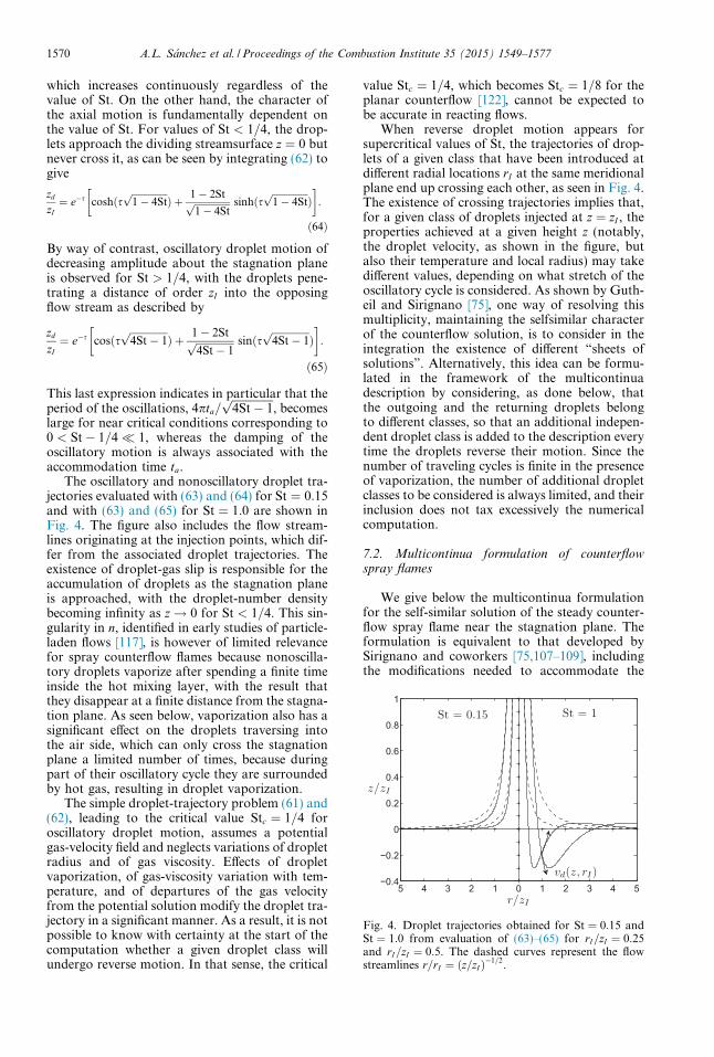
Fig. 4. Droplet trajectories obtained for St ¼ 0:15 andSt ¼ 1:0 from evaluation of (63)–(65) for rI=zI ¼ 0:25and rI=zI ¼ 0:5. The dashed curves represent the flowstreamlines r=rI ¼ ðz=zI Þ�1=2.
1570 A.L. Sanchez et al. / Proceedings of the Combustion Institute 35 (2015) 1549–1577
which increases continuously regardless of thevalue of St. On the other hand, the character ofthe axial motion is fundamentally dependent onthe value of St. For values of St < 1=4, the drop-lets approach the dividing streamsurface z ¼ 0 butnever cross it, as can be seen by integrating (62) togive
zd
zI¼ e�s coshðs
ffiffiffiffiffiffiffiffiffiffiffiffiffiffiffi1� 4Stp
Þ þ 1� 2Stffiffiffiffiffiffiffiffiffiffiffiffiffiffiffi1� 4Stp sinhðs
ffiffiffiffiffiffiffiffiffiffiffiffiffiffiffi1� 4Stp
Þ� �
:
ð64Þ
By way of contrast, oscillatory droplet motion ofdecreasing amplitude about the stagnation planeis observed for St > 1=4, with the droplets pene-trating a distance of order zI into the opposingflow stream as described by
zd
zI¼ e�s cosðs
ffiffiffiffiffiffiffiffiffiffiffiffiffiffiffi4St� 1p
Þ þ 1� 2Stffiffiffiffiffiffiffiffiffiffiffiffiffiffiffi4St� 1p sinðs
ffiffiffiffiffiffiffiffiffiffiffiffiffiffiffi4St� 1p
Þ� �
:
ð65Þ
This last expression indicates in particular that theperiod of the oscillations, 4pta=
ffiffiffiffiffiffiffiffiffiffiffiffiffiffiffi4St� 1p
, becomeslarge for near critical conditions corresponding to0 < St� 1=4� 1, whereas the damping of theoscillatory motion is always associated with theaccommodation time ta.
The oscillatory and nonoscillatory droplet tra-jectories evaluated with (63) and (64) for St ¼ 0:15and with (63) and (65) for St ¼ 1:0 are shown inFig. 4. The figure also includes the flow stream-lines originating at the injection points, which dif-fer from the associated droplet trajectories. Theexistence of droplet-gas slip is responsible for theaccumulation of droplets as the stagnation planeis approached, with the droplet-number densitybecoming infinity as z! 0 for St < 1=4. This sin-gularity in n, identified in early studies of particle-laden flows [117], is however of limited relevancefor spray counterflow flames because nonoscilla-tory droplets vaporize after spending a finite timeinside the hot mixing layer, with the result thatthey disappear at a finite distance from the stagna-tion plane. As seen below, vaporization also has asignificant effect on the droplets traversing intothe air side, which can only cross the stagnationplane a limited number of times, because duringpart of their oscillatory cycle they are surroundedby hot gas, resulting in droplet vaporization.
The simple droplet-trajectory problem (61) and(62), leading to the critical value Stc ¼ 1=4 foroscillatory droplet motion, assumes a potentialgas-velocity field and neglects variations of dropletradius and of gas viscosity. Effects of dropletvaporization, of gas-viscosity variation with tem-perature, and of departures of the gas velocityfrom the potential solution modify the droplet tra-jectory in a significant manner. As a result, it is notpossible to know with certainty at the start of thecomputation whether a given droplet class willundergo reverse motion. In that sense, the critical
value Stc ¼ 1=4, which becomes Stc ¼ 1=8 for theplanar counterflow [122], cannot be expected tobe accurate in reacting flows.
When reverse droplet motion appears forsupercritical values of St, the trajectories of drop-lets of a given class that have been introduced atdifferent radial locations rI at the same meridionalplane end up crossing each other, as seen in Fig. 4.The existence of crossing trajectories implies that,for a given class of droplets injected at z ¼ zI , theproperties achieved at a given height z (notably,the droplet velocity, as shown in the figure, butalso their temperature and local radius) may takedifferent values, depending on what stretch of theoscillatory cycle is considered. As shown by Guth-eil and Sirignano [75], one way of resolving thismultiplicity, maintaining the selfsimilar characterof the counterflow solution, is to consider in theintegration the existence of different “sheets ofsolutions”. Alternatively, this idea can be formu-lated in the framework of the multicontinuadescription by considering, as done below, thatthe outgoing and the returning droplets belongto different classes, so that an additional indepen-dent droplet class is added to the description everytime the droplets reverse their motion. Since thenumber of traveling cycles is finite in the presenceof vaporization, the number of additional dropletclasses to be considered is always limited, and theirinclusion does not tax excessively the numericalcomputation.
7.2. Multicontinua formulation of counterflowspray flames
We give below the multicontinua formulationfor the self-similar solution of the steady counter-flow spray flame near the stagnation plane. Theformulation is equivalent to that developed bySirignano and coworkers [75,107–109], includingthe modifications needed to accommodate the
A.L. Sanchez et al. / Proceedings of the Combustion Institute 35 (2015) 1549–1577 1571
presence of droplets with reverse motion. The gasphase is described in terms of the radial and axialvelocity components v ¼ AðzÞr=2 and uðzÞ, temper-ature and density T ðzÞ and qðzÞ, and mass fractionsY iðzÞ. The fuel is injected into the inert stream at agiven distance z ¼ zI � dm from the stagnationpoint, forming a polydisperse spray with a N c dif-ferent droplet classes. For each droplet class j, thesolution at a given distance z < zI is given in termsof the droplet radius ajðzÞ, temperature T j
dðzÞ,radial and axial velocity components vj
d ¼Aj
dðzÞr=2 and ujdðzÞ, and droplet number density
njðzÞ.The problem is formulated in a nondimen-
sional form that exhibits explicitly the dependenc-es on the main relevant controlling parameters,including the Stokes number St and the liquidmass-loading ratio at the injection plane a. Thespray-side values of the strain rate As, thermaldiffusivity DT s ¼ js=ðqscpÞ, gas density qs, andgas temperature T s are used as scales in definingthe dimensionless variables �z ¼ z=ðDT s=AsÞ1=2,A ¼ A=As, �u ¼ u=ðDT s AsÞ1=2, Aj
d ¼ Ajd=As, �uj
d ¼ ujd=
ðDT s AsÞ1=2, �q ¼ q=qs, T ¼ T=T s, and T jd ¼ T j
d=T s.Similarly, the spray properties at the injectionlocation are used to define �nj ¼ n=nj
o, and�aj ¼ a=aj
o. In terms of this set of variables,the gas-phase problem reduces to that ofintegrating
d
d�zð�q�uÞ þ �qA ¼ 2
3Pr
XNc
j¼1
aj
Stj �nj�ajT rkj; ð66Þ
qA2
2þ �q�u
dAd�z¼ 1
2þPr
d
d�zT r dA
d�z
� �þXNc
j¼1
aj
Stj �nj�ajT rðAjd �AÞ 1þ 2
3Prkj
� �; ð67Þ
�q�udTd�z¼ d
d�zT r dT
d�z
� ��
XNs
i¼1ho
i _wi
cpT sqsAs
� 2
3Pr
XNc
j¼1
aj
Stj �nj�ajT rkj T � T jd
1� e�kj ; ð68Þ
�q�udY i
d�z¼ 1
Lei
d
d�zT r dY i
d�z
� �þ _wi
qsAs
þð1�Y FÞ 2
3Pr
XNc
j¼1
aj
Stj �nj�ajT rkj ðif i¼FÞ
�Y i2
3Pr
XNc
j¼1
aj
Stj �nj�ajT rkj ðif i – FÞ
8>>>>><>>>>>:ð69Þ
with boundary conditions �uþ �z ¼ A� 1 ¼T �1¼ Y i�Y is ¼ 0 as �z!þ1 and A�
ffiffiffiffiffiffiffiffiffiffiffiffiqs=qA
p¼
T �T A¼ Y i�Y iA ¼ 0 as �z!�1. Correspond-ingly, the evolution of each droplet class j requiresintegration of
�ujd
dð�ajÞ3
d�z¼ � 2
3PrStj �ajT rkj; ð70Þ
ðAjdÞ
2
2þ �uj
d
dAjd
d�z¼ 1
Stj
T r
ð�ajÞ2ðA� Aj
dÞ; ð71Þ
�ujd
d�ujd
d�z¼ 1
Stj
T r
ð�ajÞ2ð�u� �uj
dÞ; ð72Þ
�ujd
dT jd
d�z¼ 2cp=cl
3PrStj
T rkj
ð�ajÞ2T � T j
d
ekj � 1� Lv
cpT s
� �ð73Þ
d
d�zð�nj�uj
dÞ þ �njAjd ¼ 0 ð74Þ
with initial conditions �aj � 1 ¼ �ujd � �uj
I ¼Aj
d � AjI ¼ T j
d � T jI ¼ �nj � 1 ¼ 0 at �z ¼ �zI . The
above equations must be supplemented with theequation of state written in nondimensional formand with the expressions (23) and (24), needed tocompute the dimensionless vaporization rate kj.Each droplet class is characterized by its mass-loading ratio aj and Stokes number Stj, obtainedfrom evaluating (2) and (60) with the propertiesof the droplet class at the injection plane. Notethat an arbitrary zero displacement of the spraystream is assumed in writing the boundary condi-tion �uþ �z ¼ 0 as �z! þ1. The location �z ¼ �z0 ofthe stagnation plane, where �u ¼ 0, is obtained aspart of the integration.
The numerical computation with the multicon-tinua formulation requires the coupled solution ofthe gas and liquid phases in an iterative schemethat may start by solving the elliptic gas-phaseproblem Eqs. (66)–(69) incorporating an adequateguess for the distributions of the droplet proper-ties. The resulting profiles T ð�zÞ, �uð�zÞ, and Að�zÞare next used in computing for each droplet classthe distributions of �a, Ad , �ud , and T d by integratingthe characteristic equations (70)–(73) for decreas-ing �z from �z ¼ �zI , while the associated numberdensity �n is obtained from (74). If the Stokes num-ber is sufficiently small, then the value of �a is seento decay to zero at a given location, where theaxial velocity �ud is still negative. The integrationof non-reversing droplets ends at that location.By way of contrast, for droplets with sufficientlylarge Stokes number the value of �ud approacheszero before complete droplet vaporization occurs.At the turning plane �z ¼ �zt, where �ud ¼ 0, the inte-gration provides nonzero finite values of �a ¼ �at,Ad ¼ Adt , and T d ¼ T dt . On the other hand, thelocal axial-velocity distribution
�ud ¼ 2T r
t �ut
St�a2t
� �1=2
ð�z� �ztÞ1=2; ð75Þ
obtained from (72) in terms of the local values ofthe gas temperature T t and gas velocity �ut (withthe minus and plus signs corresponding to outgo-ing and returning droplets, respectively), can beused in (74) to show that the droplet number den-sity diverges at the turning plane according to
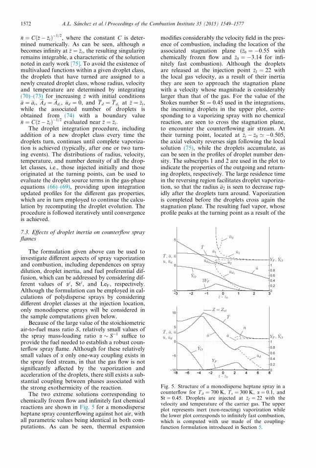
Fig. 5. Structure of a monodisperse heptane spray in acounterflow for T A ¼ 700 K, T s ¼ 300 K, a ¼ 0:1, andSt ¼ 0:45. Droplets are injected at �zI ¼ 22 with thevelocity and temperature of the carrier gas. The upperplot represents inert (non-reacting) vaporization whilethe lower plot corresponds to infinitely fast combustion,which is computed with use made of the coupling-function formulation introduced in Section 5.
1572 A.L. Sanchez et al. / Proceedings of the Combustion Institute 35 (2015) 1549–1577
�n ¼ Cð�z� �ztÞ�1=2, where the constant C is deter-mined numerically. As can be seen, although nbecomes infinity at �z ¼ �zt, the resulting singularityremains integrable, a characteristic of the solutionnoted in early work [75]. To avoid the existence ofmultivalued functions within a given droplet class,the droplets that have turned are assigned to anewly created droplet class, whose radius, velocityand temperature are determined by integrating(70)–(73) for increasing �z with initial conditions�a ¼ �at, Ad ¼ Adt , �ud ¼ 0, and T d ¼ T dt at �z ¼ �zt,while the associated number of droplets isobtained from (74) with a boundary value�n ¼ Cð�z� �ztÞ�1=2 evaluated near �z ¼ �zt.
The droplet integration procedure, includingaddition of a new droplet class every time thedroplets turn, continues until complete vaporiza-tion is achieved (typically, after one or two turn-ing events). The distributions of radius, velocity,temperature, and number density of all the drop-let classes, i.e., those injected initially and thoseoriginated at the turning points, can be used toevaluate the droplet source terms in the gas-phaseequations (66)–(69), providing upon integrationupdated profiles for the different gas properties,which are in turn employed to continue the calcu-lation by recomputing the droplet evolution. Theprocedure is followed iteratively until convergenceis achieved.
7.3. Effects of droplet inertia on counterflow sprayflames
The formulation given above can be used toinvestigate different aspects of spray vaporizationand combustion, including dependences on spraydilution, droplet inertia, and fuel preferential dif-fusion, which can be addressed by considering dif-ferent values of aj, Stj, and LeF, respectively.Although the formulation can be employed in cal-culations of polydisperse sprays by consideringdifferent droplet classes at the injection location,only monodisperse sprays will be considered inthe sample computations given below.
Because of the large value of the stoichiometricair-to-fuel mass ratio S, relatively small values ofthe spray mass-loading ratio a � S�1 suffice toprovide the fuel needed to establish a robust coun-terflow spray flame. Although for these relativelysmall values of a only one-way coupling exists inthe spray feed stream, in that the gas flow is notsignificantly affected by the vaporization andacceleration of the droplets, there still exists a sub-stantial coupling between phases associated withthe strong exothermicity of the reaction.
The two extreme solutions corresponding tochemically frozen flow and infinitely fast chemicalreactions are shown in Fig. 5 for a monodisperseheptane spray counterflowing against hot air, withall parametric values being identical in both com-putations. As can be seen, thermal expansion
modifies considerably the velocity field in the pres-ence of combustion, including the location of theassociated stagnation plane (�z0 ¼ �0:55 withchemically frozen flow and �z0 ¼ �3:14 for infi-nitely fast combustion). Although the dropletsare released at the injection point �zI ¼ 22 withthe local gas velocity, as a result of their inertiathey are seen to approach the stagnation planewith a velocity whose magnitude is considerablylarger than that of the gas. For the value of theStokes number St ¼ 0:45 used in the integrations,the incoming droplets in the upper plot, corre-sponding to a vaporizing spray with no chemicalreaction, are seen to cross the stagnation plane,to encounter the counterflowing air stream. Attheir turning point, located at �zt � �z0 ’ �0:505,the axial velocity reverses sign following the localsolution (75), while the droplets accumulate, ascan be seen in the profiles of droplet number den-sity. The subscripts 1 and 2 are used in the plot toindicate the properties of the outgoing and return-ing droplets, respectively. The large residence timein the reversing region facilitates droplet vaporiza-tion, so that the radius �a2 is seen to decrease rap-idly after the droplets turn around. Vaporizationis completed before the droplets cross again thestagnation plane. The resulting fuel vapor, whoseprofile peaks at the turning point as a result of the
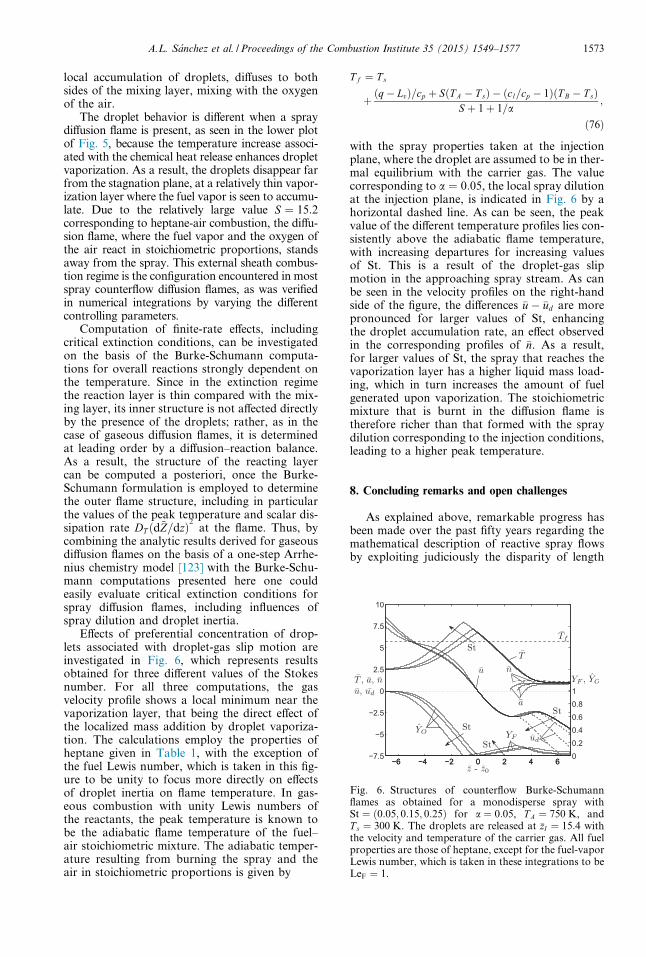
Fig. 6. Structures of counterflow Burke-Schumannflames as obtained for a monodisperse spray withSt ¼ ð0:05; 0:15; 0:25Þ for a ¼ 0:05, T A ¼ 750 K, andT s ¼ 300 K. The droplets are released at �zI ¼ 15:4 withthe velocity and temperature of the carrier gas. All fuelproperties are those of heptane, except for the fuel-vaporLewis number, which is taken in these integrations to beLeF ¼ 1.
A.L. Sanchez et al. / Proceedings of the Combustion Institute 35 (2015) 1549–1577 1573
local accumulation of droplets, diffuses to bothsides of the mixing layer, mixing with the oxygenof the air.
The droplet behavior is different when a spraydiffusion flame is present, as seen in the lower plotof Fig. 5, because the temperature increase associ-ated with the chemical heat release enhances dropletvaporization. As a result, the droplets disappear farfrom the stagnation plane, at a relatively thin vapor-ization layer where the fuel vapor is seen to accumu-late. Due to the relatively large value S ¼ 15:2corresponding to heptane-air combustion, the diffu-sion flame, where the fuel vapor and the oxygen ofthe air react in stoichiometric proportions, standsaway from the spray. This external sheath combus-tion regime is the configuration encountered in mostspray counterflow diffusion flames, as was verifiedin numerical integrations by varying the differentcontrolling parameters.
Computation of finite-rate effects, includingcritical extinction conditions, can be investigatedon the basis of the Burke-Schumann computa-tions for overall reactions strongly dependent onthe temperature. Since in the extinction regimethe reaction layer is thin compared with the mix-ing layer, its inner structure is not affected directlyby the presence of the droplets; rather, as in thecase of gaseous diffusion flames, it is determinedat leading order by a diffusion–reaction balance.As a result, the structure of the reacting layercan be computed a posteriori, once the Burke-Schumann formulation is employed to determinethe outer flame structure, including in particularthe values of the peak temperature and scalar dis-sipation rate DT ðd~Z=dzÞ2 at the flame. Thus, bycombining the analytic results derived for gaseousdiffusion flames on the basis of a one-step Arrhe-nius chemistry model [123] with the Burke-Schu-mann computations presented here one couldeasily evaluate critical extinction conditions forspray diffusion flames, including influences ofspray dilution and droplet inertia.
Effects of preferential concentration of drop-lets associated with droplet-gas slip motion areinvestigated in Fig. 6, which represents resultsobtained for three different values of the Stokesnumber. For all three computations, the gasvelocity profile shows a local minimum near thevaporization layer, that being the direct effect ofthe localized mass addition by droplet vaporiza-tion. The calculations employ the properties ofheptane given in Table 1, with the exception ofthe fuel Lewis number, which is taken in this fig-ure to be unity to focus more directly on effectsof droplet inertia on flame temperature. In gas-eous combustion with unity Lewis numbers ofthe reactants, the peak temperature is known tobe the adiabatic flame temperature of the fuel–air stoichiometric mixture. The adiabatic temper-ature resulting from burning the spray and theair in stoichiometric proportions is given by
T f ¼ T s
þ ðq� LvÞ=cp þ SðT A � T sÞ � ðcl=cp � 1ÞðT B � T sÞS þ 1þ 1=a
;
ð76Þ
with the spray properties taken at the injectionplane, where the droplet are assumed to be in ther-mal equilibrium with the carrier gas. The valuecorresponding to a ¼ 0:05, the local spray dilutionat the injection plane, is indicated in Fig. 6 by ahorizontal dashed line. As can be seen, the peakvalue of the different temperature profiles lies con-sistently above the adiabatic flame temperature,with increasing departures for increasing valuesof St. This is a result of the droplet-gas slipmotion in the approaching spray stream. As canbe seen in the velocity profiles on the right-handside of the figure, the differences �u� �ud are morepronounced for larger values of St, enhancingthe droplet accumulation rate, an effect observedin the corresponding profiles of �n. As a result,for larger values of St, the spray that reaches thevaporization layer has a higher liquid mass load-ing, which in turn increases the amount of fuelgenerated upon vaporization. The stoichiometricmixture that is burnt in the diffusion flame istherefore richer than that formed with the spraydilution corresponding to the injection conditions,leading to a higher peak temperature.
8. Concluding remarks and open challenges
As explained above, remarkable progress hasbeen made over the past fifty years regarding themathematical description of reactive spray flowsby exploiting judiciously the disparity of length
1574 A.L. Sanchez et al. / Proceedings of the Combustion Institute 35 (2015) 1549–1577
and time scales present in the problem. Reasonsfor the validity and limitations of the continuumdescription of the gas and liquid phases in thevaporization and combustion of sprays in dieselengines and liquid-fueled gas turbines have beenindicated. The homogenized description can beused for the direct numerical simulation of turbu-lent reacting sprays and also as starting point forReynolds-averaged representations of these flows.We have aimed to show in this paper how consid-eration of canonical model problems has beeninstrumental for the analysis of spray-combustionphenomena. In particular, we have tried to illus-trate, with the examples of the evolving spraycloud and the counterflow configuration, how bythe careful nondimensional formulation of theproblems they can become a tool to gain under-standing of the dynamics of sprays. Thus, collec-tive effects of cloud vaporization have beeninvestigated in a spherically symmetrical configu-ration, accounting for the significant separateeffects of the initial liquid mass loading and theratio of the heat-conduction time across the cloudand the time of droplet vaporization. Effects ofdroplet inertia on spray diffusion flames have beeninvestigated in connection with the counterflowconfiguration.
Finite-rate effects, controlling the transitionfrom the non-reacting mode to the diffusion-con-trolled mode, have been limited here to an Arrhe-nius reaction for the computation of ignition inmixing-layer configurations. The mixing-layerignition results should be extended in future workto more realistic chemical schemes, needed forreliable predictions of finite-rate chemical effectsin spray flames, including also critical conditionsfor strain-induced extinction, considered earlier[75]. The associated chemistry involves typicallyhundreds of intermediate species and a few thou-sand elementary reactions [124]. Chemical preta-bulation in turbulent-combustion models benefitsfrom investigations of surrogates of these complexfuels, whose chemical mechanisms are starting torequire thorough uncertainty-quantification anal-yses as the number of kinetic parameters becomeslarger [125,126]. Systematic chemical-kineticreduced mechanisms based on steady-stateapproximations for intermediates [85] can be use-ful in numerical and asymptotic investigations ofspray flames, including computations of pollutantemissions (see, e.g., the discussion in Section 5.4).
Despite the significant progress made in recentyears, our understanding of spray-combustionphenomena is far from complete. Improveddescriptions of the hydrodynamic instabilitiesleading to liquid-jet atomization and of dropletbreakup and coalescence processes occurring inthe secondary atomization region are needed.Although investigations focused on the dynamicsof momentum transfer in particle-laden turbulentflows have contributed valuable understanding of
the essential mechanisms leading to droplet dis-persion in spray jets, including effects associatedwith turbulent kinetic-energy modulation by thesolid phase as well preferential concentration[18] (both having important implications for sub-grid-scale modeling [127–130]), the needed exten-sion to spray turbulent combustion necessitatesthe additional consideration of two-way massand thermal-energy transfer processes. More workon the effects of convection at interdroplet anddroplet scales is also needed, to address influencesof turbulence on homogenized descriptions andon droplet-source submodels.
The current trends that gear designs of dieselengines towards higher compression ratios pro-mote increasing interest in spray combustionunder supercritical conditions [131]. Since theliquid fuel is seldom preheated before injection,the presence of both subcritical and supercriticalconditions in the combustion chamber is war-ranted. This requires simultaneous considerationof the liquid phase, which may contain dropletsand ligaments, in addition to the gas phase andthe supercritical mixture, with the spatial locationof the transcritical conditions being determined bythe capabilities of the hot environment to heat upthe liquid fuel to its critical temperature. Clearly,the different simplifications stemming from thecondition ql=q� 1 do not apply to the descrip-tion of the supercritical fluid. Although analysesof droplet vaporization and combustion haveaddressed supercritical conditions [132], includingtransient effects associated with shorter life times[20,133], more work is needed to provide reliabledroplet submodels.
Considerable advances have been made inrecent years in understanding the onset and devel-opment of thermoacoustic instabilities in gaseouscombustion [134–136]. Extension to spray com-bustion of predictive capabilities developed forgaseous combustion instabilities requires the con-sideration of finite inertia of the liquid phase,which responds to pressure oscillations with acharacteristic delay that depends on the Stokesnumber [137,138]. In this regard, recent investiga-tions have been carried out to model spray-flametransfer functions using numerical simulations[139] and experiments [140–142], of interest forthe development of reduced-order models.
A number of modeling issues remain to beresolved. For example, the direct extension tospray combustion of flamelet approaches for themodeling of turbulent reacting flows appears tobe nontrivial. Since both premixed and non-pre-mixed flames can coexist in liquid-fueled burners[64,69–73,143], the accuracy of modeling strate-gies based on either premixed or non-premixedflamelets is necessarily limited, so that the use ofhybrid models must be considered in spray-com-bustion applications. In contrast to gaseous flam-elets, in which the local strain rate is often

A.L. Sanchez et al. / Proceedings of the Combustion Institute 35 (2015) 1549–1577 1575
sufficient to parametrize the entire manifold ofsolutions, spray flamelets display a richer para-metric dependence, as can be inferred from thecounterflow formulation of Section 7. On theother hand, the gas mixture fraction, which pro-vides a one-to-one mapping between physicaland mixture-composition spaces in gaseous com-bustion, becomes non-monotonic in spray flamesbecause of droplet vaporization [144,145]. This,in turn, prevents straightforward tabulation ofthe flamelet variables, and introduces additionaldifficulties for modeling the scalar dissipation rate,which strongly departs from its gaseous counter-part [64]. To palliate this lack of monotonicity, amixture fraction incorporating also the localliquid mass fraction may be derived, in whichthe vaporization source term does not appearexplicitly. Nevertheless, the presence of the fuelin liquid phase in the mixture fraction requiresmodeling of additional terms related to the drop-let-gas slip velocity and to the non-diffusive char-acter of droplet transport [146,147]. Alternativedefinitions of mixture-fraction variables incorpo-rating the liquid fuel have been proposed [148],but those appear to become more effective fornumerical simulations that resolve the spray downto droplet scales including the liquid–gas inter-face. A different approach that parallels the treat-ment of gaseous combustion involves the use of amixture fraction that satisfies a source-free trans-port equation [67], thereby simplifying greatlythe numerical integration. Such a mixture fractioncannot be derived, however, from the originalconservation equations, a shortfall of the formula-tion that necessarily limits its descriptive capabil-ity (e.g., the location of the stoichiometricmixture fraction in physical space is not relatedin any way to the flame position). Clearly, manyof these modeling difficulties are not present whenthe droplets are so small that they heat up andvaporize very fast while following closely the gas-eous streamlines, under which conditions a quasi-gaseous flamelet formulation based on the coun-terflow configuration may be used, includingmodified boundary conditions on the fuel sidethat account for the enthalpy loss required fordroplet vaporization [149].
Acknowledgments
Amable Linan’s interest in spray combustionoriginated while collaborating at Yale Universitywith Sandro Gomez, whose insightful inputguided the initial developments of many of theideas presented here. Much of our recent workon spray combustion has been carried out incollaboration with Forman A. Williams andDaniel Martınez-Ruiz. This work was supportedby the Spanish MCINN through project
#CSD2010–00011. Javier Urzay acknowledgessupport from the 2011–2012 Postdoctoral Fellow-ship for Excellence in Research, Ibercaja Founda-tion at Zaragoza (Spain).
References
[1] F.A. Williams, Combust. Flame 21 (1973) 1–31.[2] C.K. Law, Prog. Energy Combust. Sci. 8 (1982)
171–201.[3] G.M. Faeth, Prog. Energy Combust. Sci. 9 (1983)
1–76.[4] W.A. Sirignano, Prog. Energy Combust. Sci. 9
(1983) 291–322.[5] J. Bellan, Prog. Energy Combust. Sci. 26 (2000)
329–366.[6] H.H. Chiu, Prog. Energy Combust. Sci. 26 (2000)
381–416.[7] K. Annamalai, W. Ryan, Prog. Energy Combust.
Sci. 18 (1992) 221–295.[8] A. Umemura, Prog. Energy Combust. Sci. 20
(1994) 325–372.[9] W.A. Sirignano, Prog. Energy Combust. Sci.
(2014) (in press).[10] S.K. Aggarwal, Prog. Energy Combust. Sci. 24
(1998) 565–600.[11] X. Jiang, G.A. Siamas, K. Jagus, T.G. Karyiannis,
Prog. Energy Combust. Sci. 36 (2010) 131–167.[12] E. Gutheil, in: B. Merci, D. Roekaerts, A. Sadiki
(Eds.), Experiments and Numerical Simulations ofDiluted Spray Turbulent Combustion, Springer-Verlag, 2011, pp. 1–39.
[13] P. Jenny, D. Roekaerts, N. Beishuizen, Prog.Energy Combust. Sci. 38 (2012) 846–887.
[14] S.P. Lin, R.D. Reitz, Annu. Rev. Fluid Mech. 30(1998) 85–105.
[15] J.C. Lasheras, E. Hopfinger, Annu. Rev. FluidMech. 32 (2000) 275–308.
[16] C. Dumouchel, Exp. Fluids 45 (2008) 371–422.[17] C.T. Crowe, T.R. Troutt, J.N. Chung, Annu. Rev.
Fluid Mech. 28 (1996) 11–43.[18] S. Balachandar, J.K. Eaton, Annu. Rev. Fluid
Mech. 42 (2009) 111–133.[19] S. Subramaniam, Prog. Energy Combust. Sci. 38
(2013) 215–245.[20] W.A. Sirignano, Fluid Dynamics and Transport of
Droplets and Sprays, 2nd Ed., Cambridge Univer-sity Press, 2010.
[21] A.H. Lefebvre, Atomization and Sprays, Hemi-sphere Publishing Corporation, 1989.
[22] K.K. Kuo, R. Acharya, Fundamentals of Turbulentand Multiphase Combustion, Wiley and Sons, 2012.
[23] H.H. Chiu, N. Chigier (Eds.), Mechanics andCombustion of Droplets and Sprays, Begell HousePublishers, 1995.
[24] K.K. Kuo (Ed.), Recent Advances in SprayCombustion, 1996, Prog. Aeronaut. Astronaut.171.
[25] G.I. Taylor, Proc. Roy. Soc. Lond. 253 (1959) 296–312.
[26] E. Giannadakis, M. Gavaises, C. Arcoumanis, J.Fluid Mech. 153 (2008) 153–193.
[27] G.I. Taylor, Seventh International Congress ofApplied Mechanics 2 (1948) 280–285.
1576 A.L. Sanchez et al. / Proceedings of the Combustion Institute 35 (2015) 1549–1577
[28] G.I. Taylor, Proc. Roy. Soc. Lond. 253 (1959) 313–321.
[29] O. Desjardins, H. Pitsch, Atomization and Sprays20 (2010) 311–336.
[30] J. Shinjo, A. Umemura, Int. J. Multiphase Flow 36(2010) 513–532.
[31] S. Rana, M. Herrmann, Phys. Fluids 23 (2011)091109.
[32] J. Shinjo, A. Umemura, Proc. Combust. Inst. 33(2011) 2089–2097.
[33] V. Le Chenadec, H. Pitsch, J. Comput. Phys. 249(2013) 185–203.
[34] E. Longmire, J. Eaton, J. Fluid Mech. 236 (1992)217–257.
[35] H.S. Carslaw, J.C. Jaeger, Conduction of Heat inSolids, 2nd Ed., Oxford University Press, 1959, pp.233–237.
[36] C.K. Law, W.A. Sirignano, Combust. Flame 28(1977) 175–186.
[37] B. Abramzon, W.A. Sirignano, Int. J. Heat MassTransfer 32 (1989) 1605–1618.
[38] C.T. Crowe, D.E. Stock, M.P. Sharma, ASMETrans. Series I–J. Fluids Eng. 99 (1977) 325–332.
[39] A. Bermudez, J.L. Ferrın, A. Linan, Combust.Theor. Model. 11 (2007) 949–976.
[40] A. Bermudez, J.L. Ferrın, A. Linan, L. Saavedra,Combust. Flame 158 (2011) 1852–1865.
[41] X.Y. Zhao, D.C. Haworth, Combust. Flame (2014)(in press).
[42] P. Moin, S.V. Apte, AIAA J. 44 (2006) 698–708.[43] N. Patel, M. Kirtas, V. Sankaran, S. Menon,
Proc. Combust. Inst. 31 (2007) 2327–2334.[44] G. Hannebique, P. Sierra, E. Riber, B. Cuenot,
Flow Turbul. Combust. 90 (2013) 449–469.[45] F.A. Williams, Combustion Theory, Second ed.,
Benjamin Cummings, Menlo Park, CA, 1985.[46] D. Kah, F. Laurent, L. Freret, et al., Flow Turbul.
Combust. 85 (2010) 649–676.[47] C. Yuan, R.O. Fox, J. Comput. Phys. 230 (2011)
8216–8246.[48] R.O. Fox, Annu. Rev. Fluid Mech. 44 (2012) 47–76.[49] F.A. Williams, J. Chem. Phys. 33 (1960) 133–144.[50] S.S. Sadhal, P.S. Ayyaswamy, J. Fluid Mech. 133
(1983) 65–81.[51] D. Kassoy, F.A. Williams, AIAA J. 6 (1968) 1961–
1965.[52] M. Hermanns, High order numerical methods
applied to the analysis of transport phenomena incombustion. PhD Dissertation, 2006, UPM,Madrid.
[53] J. Urzay, H. Pitsch, A. Linan, Annual ResearchBriefs, Center for Turbulence Research, StanfordUniversity/ NASA Ames, 2011, pp. 199–211.
[54] R.S. Miller, K. Harstad, J. Bellan, Int. J. Multi-phase Flow 24 (1998) 1025–1055.
[55] Shashank, E. Knudsen, H. Pitsch, AnnualResearch Briefs, Center for Turbulence Research,Stanford University/ NASA Ames, 2011, pp. 213–224.
[56] G. Del Alamo, F.A. Williams, J. Fluid Mech. 580(2007) 219–249.
[57] S.C.R. Dennis, J.D.A. Walker, J. Fluid Mech. 48(1971) 771–789.
[58] M. Queiroz, S-C. Yao, Combust. Flame 76 (1989)351–368.
[59] A. Linan, in: R. Borghi, P. Clavin, A. Linan, P.Pelce, G.I. Sivashinsky (Eds.) Theory of Droplet
Vaporization and Combustion, CEA-EDF INRIA59. Editions Eyrolles, pp. 73–103.
[60] A.H. Lefebvre, Gas Turbine Combustion, Taylorand Francis, 1998.
[61] J. Heywood, Internal Combustion Engines, Mc-Graw Hill, 1988.
[62] S.K. Marley, E.J. Welle, K.M. Lyons, Transact.ASME 126 (2004) 254–257.
[63] V.M. Reddy, D. Trivedi, S. Kumar, Combust. Sci.Technol. 184 (2012) 44–63.
[64] D. Martınez-Ruiz, J. Urzay, A.L. Sanchez, A.Linan, F.A. Williams, J. Fluid Mech. 734 (2013)387–423.
[65] B. Lazaro, J.C. Lasheras, J. Fluid Mech. 235(1997) 179–221.
[66] C. Lacour, D. Durox, S. Ducruix, M. Massot,Exp. Fluids 51 (2011) 295–311.
[67] N. Peters, Turbulent Combustion, Cambridge Uni-versity Press, 2000.
[68] E. Gutheil, Combust. Sci. Tech. 105 (1995) 265–278.
[69] S.C. Li, F.A. Williams, Proc. Combust. Inst. 26(1996) 1017–1024.
[70] S.K. Marley, E.J. Welle, K.M. Lyons, W.L.Roberts, Exp. Therm. Fluid Sci. 29 (2004) 23–31.
[71] J. Reveillon, L. Vervisch, J. Fluid Mech. 537(2005) 317–347.
[72] M. Mikami, Y. Mizuta, Y. Tsuchida, N. Kojima,Proc. Combust. Inst. 32 (2009) 2223–2230.
[73] K. Luo, H. Pitsch, M.G. Pai, O. Desjardins, Proc.Combust. Inst. 33 (2011) 2143–2152.
[74] S.C. Li., Prog. Energy Combust. Sci. 23 (1997)303–347.
[75] E. Gutheil, W.A. Sirignano, Combust. Flame 113(1998) 92–105.
[76] J. Buckmaster, Prog. Energy Combust. Sci. 28(2002) 435–475.
[77] S.H. Chung, Proc. Combust. Inst. 31 (2007) 877–892.
[78] J.B. Greenberg, L.S. Kagan, G.I. Sivashinsky,Combust. Theor. Model. 17 (2013) 1053–1066.
[79] M. Mikami, S. Miyamoto, N. Kojima, Proc.Combust. Inst. 29 (2002) 593–599.
[80] J. Arrieta-Sanagustın, A.L. Sanchez, A. Linan, F.A.Williams, Fuel Process. Technol. 107 (2013) 81–92.
[81] V.A. Shvab, Gos. Energ. izd. M-L (1948).[82] Y.B. Zeldovich, Zhurnal Tekhnicheskoi Fiziki 19
(1949) 1199-1210. English translation: On thetheory of combustion of initially unmixed gases,NACA Tehnical Memorandum 1296 (1951).
[83] A. Linan, The structure of diffusion flames, in: M.Onofri, A. Tesei (Eds.), Fluid Dynamical Aspectsof Combustion Theory, Longman Scientific Tech-nical, Essex, 1991, pp. 11–19.
[84] A. Linan, Diffusion-controlled combustion, in:H. Aref, J.W. Phillips (Eds.), Mechanics for aNew Millennium, Kluwer Academics, Dordrecht,2001, pp. 487–502.
[85] N. Peters, B. Rogg, Reduced kinetic mechanismsfor applications in combustion systems, in: LectureNotes in Physics, Springer-Verlag, 1993.
[86] F.A. Williams, Proc. Combust. Inst. 24 (1992) 1–17.[87] A.L. Sanchez, A. Lepinette, M. Bollig, A. Linan,
B. Lazaro, Combust. Flame 123 (2000) 436–464.[88] T. Suzuki, H.H. Chiu, Proceedings of The Ninth
International Symposium on Space Technologyand Science, 1971, pp. 145–154.
A.L. Sanchez et al. / Proceedings of the Combustion Institute 35 (2015) 1549–1577 1577
[89] H.H. Chiu, T.M. Liu, Combust. Sci. Technol. 17(1977) 127–142.
[90] M. Labowksy, D.E. Rosner, in: J. Zung (Ed.),Group Combustion of Droplets in Fuel Clouds,American Chemical Society, 1978, pp. 63–79.
[91] H.H. Chiu, Y. Kim, J. Croke, Proc. Combust. Inst.19 (1982) 971–980.
[92] S.M. Correa, M. Sichel, Proc. Combust. Inst. 19(1982) 981–991.
[93] S.M. Correa, M. Sichel, Combust. Sci. Tech. 28(1982) 121–130.
[94] M. Yang, M. Sichel, AIAA paper 90-3060 (1990).[95] G. Continillo, W.A. Sirignano, Proc. Combust.
Inst. 22 (1988) 1941–1949.[96] S.K. Aggarwal, W.A. Sirignano, Combust. Flame
62 (1985) 69–84.[97] A. Linan, F.A. Williams, Combust. Sci. Tech. 105
(1995) 245–263.[98] J. Arrieta-Sanagustın, A.L. Sanchez, A. Linan,
F.A. Williams, J. Fluid Mech. 675 (2011) 435–464.[99] G.M. Corcos, F.S. Sherman, J. Fluid Mech. 73
(1976) 241–264.[100] C.F. Edwards, R.C. Rudoff, Proc. Combust. Inst.
23 (1990) 1353–1359.[101] I.K. Puri, P.A. Libby, Combust. Sci. Tech. 66
(1989) 267–292, 1989.[102] G. Chen, A. Gomez, Proc. Combust. Inst. 24
(1992) 1531–1539.[103] S.C. Li, P.A. Libby, F.A. Williams, Combust.
Flame 94 (1993) 161–177.[104] M. Massot, M. Kumar, M.D. Smooke, A. Gomez,
Proc. Combust. Inst. 27 (1998) 1975–1983.[105] S.C. Li, F.A. Williams, Proc. Combust. Inst. 28
(2000) 1031–1038.[106] V.S. Santorio, A. Gomez, Proc. Combust. Inst. 29
(2002) 585–592.[107] G. Continillo, W.A. Sirignano, Combust. Flame 81
(1990) 325–340.[108] D. Schlotz, E. Gutheil, Combust. Sci. Tech. 158
(2000) 195–210.[109] E. Gutheil, Z. Angew, Math. Mech. 81 (2001)
S533–S536.[110] H. Watanabe, R. Kurose, S-M. Hwang, F.
Akamatsu, Combust. Flame 148 (2007) 234–248.[111] H. Watanabe, R. Kurose, S. Komori, H. Pitsch,
Combust. Flame 152 (2008) 2–13.[112] R.J. Kee, K. Yamashita, H. Zhu, A.M. Dean,
Combust. Flame 158 (2011) 1129–1139.[113] J. Hayashi, H. Watanabe, R. Kurose, F. Akama-
tsu, Combust. Flame 158 (2011) 2559–2568.[114] H. Zhu, R.J. Kee, L. Chen, J. Cao, M. Xu, Y.
Zhang, Comb. Theory Model. 16 (2012) 715–735.[115] C. Wang, A.M. Dean, H. Zhu, R.J. Kee, Combust.
Flame 160 (2013) 265–275.[116] A. Vie, B. Franzellia, Y. Gao, T. Lu, H. Wang,
M. Ihme, Proc. Combust. Inst. 35 (2015), toappear.
[117] A. Robinson, Comm. Pure Appl. Math. 9 (1956)69–84.
[118] J. Fernandez de la Mora, P. Riesco-Chueca, J.Fluid Mech. 195 (1988) 1–21.
[119] G.F. Carrier, F.E. Fendell, S.F. Fink IV, C.N.Folley, Combust. Flame 126 (2001) 1630–1639.
[120] I.K. Puri, P.A. Libby, Combust. Sci. Tech. 66(1989) 267–279.
[121] N.-H. Chen, B. Rogg, K.N.C. Bray, Proc. Com-bust. Inst. 24 (1992) 1513–1521.
[122] J.L. Castillo, J. Macıas, P.L. Garcıa-Ybarra, J.Aerosol Sci. 28 (1997) S733–S734.
[123] A. Linan, Acta Astronautica 1 (1974) 1007–1039.[124] Z. Luo, S. Som, S.M. Sarathy, et al., Combust.
Theory Model. 18 (2014) 187–203.[125] D.A. Sheen, H. Wang, Combust. Flame 158 (2011)
2358–2374.[126] J. Urzay, N. Kseib, P.G. Constantine, D.F.
Davidson, G. Iaccarino, Annual Research Briefs,Center for Turbulence Research, Stanford Univer-sity/ NASA Ames, 2012, pp. 3–16.
[127] W.R. Michaek, J.G.M. Kuerten, J.C.H. Zeegers,R. Liew, J. Pozorski, B.J. Geurts, Phys. Fluids 25(2013) 123302.
[128] G. Jin, J. Zhang, G.-W. He, L.-P. Wang, PhysicaScripta 142 (2010) 014061.
[129] P. Fede, O. Simonin, P. Villedieu, K.D. Squires, in:Proceedings of the Summer Program, Center forTurbulence Research, Stanford University/NASAAmes, 2006, pp. 247–248.
[130] M. Moreau, O. Simonin, B. Bedat, Flow Turbul.Combust. 86 (2011) 563–583.
[131] R.N. Dahms, J. Manin, L.M. Pickett, J.C. Oefe-lein, Proc. Combust. Inst. 34 (2013) 1667–1675.
[132] C. Sanchez-Tarifa, A. Crespo, E. Fraga, Astro-naut. Acta 17 (1972) 685–692.
[133] J.S. Shuen, V. Yang, C.C. Hsiao, Combust. Flame89 (1992) 299–319.
[134] T. Poinsot, D. Veynante, Theoretical and Numer-ical Combustion, R.T. Edwards, 2001.
[135] T. Lieuwen, V. Yang, Combustion Instabilities inGas Turbine Engines, 2005, Prog. Aeronaut.Astronaut. 210.
[136] H. Ying, V. Yang, Prog. Energy Combust. Sci. 35(2009) 293, 264.
[137] P. Clavin, J. Sung, Combust. Sci. Tech. 78 (1991)265–288.
[138] C. Clanet, G. Searby, P. Clavin, J. Fluid Mech.385 (1999) 157–197.
[139] C. Pera, J. Reveillon, Proc. Combust. Inst. 31(2007) 2283–2290.
[140] P. Gajan, A. Strzelecki, B. Platet, R. Lecourt, F.Giuliani, AIAA J. 23 (2007) 390–397.
[141] M. De la Cruz Garcia, E. Mastorakos, Combust.Flame 32 (2008) 2397–2404.
[142] T. Providakis, L. Zimmer, P. Scouflaire, S. Duc-ruix, J. Eng. Gas Turbines Power 134 (2012)111503–111508.
[143] B. Franzelli, B. Fiorina, N. Darabiha, Proc.Combust. Inst. 34 (2013) 1659–1666, 2013.
[144] C. Hollmann, E. Gutheil, Proc. Combust. Inst. 26(1996) 1731–1738.
[145] C. Hollmann, E. Gutheil, Combust. Sci. Tech. 135(1998) 175–192.
[146] J. Urzay, D. Martınez-Ruiz, A L. Sanchez, A.Linan, F.A. Williams, Annual Research Briefs,Center for Turbulence Research, Stanford Univer-sity/ NASA Ames, 2013, pp. 107–122.
[147] B. Franzelli, A. Vie, B. Fiorina, N. Darabiha, M.Ihme, Annual Research Briefs, Center for Turbu-lence Research, Stanford University/ NASAAmes, 2013, pp. 93–106.
[148] R.W. Bilger, Combust. Flame 158 (2011) 191–202.[149] Y. Baba, R. Kurose, J. Fluid Mech. 612 (2008)
45–79.