Embed Size (px)
Citation preview
Leçon 20Le bac à sable
Créer un bac à sable Projeter et tamponner
Google SketchUp 6: Advanced Exercises
184
4. The roadway lines are projected onto the surface, and become part of the TIN group. (If you are still in X-Ray mode, you can see the roadway lines through the lake.)
5. Though it is not necessary for this simple model, the Text tool is handy for checking elevations. First, Explode the group. Then activate Text and click any point. The default text is the point’s coordinates, the last of which is the point’s elevation.
6. To create a bridge, draw lines between two sets of intersection points, all of which should have the same elevation.
7. Erase any extra lines, and apply colors if you want. Now you have a roadway over hilly terrain, with a bridge crossing the lake.
StampThis exercises uses the copy of the model you created earlier.1. This tool requires one or more 2D or 3D objects, but
you cannot select lines or curves. So add two lines between the open ends of the roadway.
2. Click Stamp (Tools / Sandbox / Stamp).
SketchUp version 6.0 exercices
210
175
7 Sandbox ToolsNOTE: Sandbox tools are available in Google SketchUp Pro only!
Google SketchUp’s sandbox tools enable you to create terrains, as well as other organic shapes. The actual surface created as called a TIN - triangulated irregular network. A TIN is simply several connected flat triangular faces that, when smoothed, appear like one continuos smooth surface.You can create a TIN from scratch as a flat grid, or create it from a set of contours. You can also import a TIN from a *.dtm file. TIN contours can be created within Google SketchUp or imported. Or you could import an image of a site plan or contour map and use Freehand to trace its contours.
NOTE: If you have a site map and want to create a stepped (not smooth) topographical surface, see “Projecting an Image onto a Topographical Face” on page 91.
Creating a Sandbox (TIN)1. Set the Units to Decimal Meters.
2. In order for the sandbox tools to be available, you must activate them. Open Window / Preferences to the Extensions page and check Sandbox Tools.
The Sandbox toolbar should now appear.
NOTE: If you want to disable the Sandbox tools, go back to the Preferences. You’ll need to close Google SketchUp and reopen it to see the change.
Sandbox from ScratchWith this tool, you can create a flat TIN surface, divided into a grid. This TIN surface can then be modified using the other sandbox tools.1. Click From Scratch.
2. The VCB indicates the Grid Spacing. Enter 5 (the meter unit is assumed since you set the units).
3. Click to start the first side of the grid and move the mouse to create the first side. Do not click yet. The tick marks are 5m apart.
4. You can use the VCB to enter an exact length, Type 100 and press Enter. The side is extended to be 100m long, and you may have to zoom out to see it.
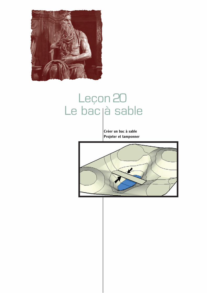
NOTE : Le Bac à sable n'est disponible que dans Google SketchUp Pro
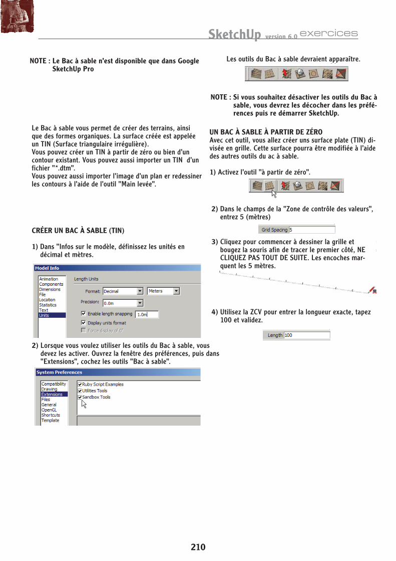
NOTE : Si vous souhaitez désactiver les outils du Bac à sable, vous devrez les décocher dans les préfé-rences puis re démarrer SketchUp.
Le Bac à sable vous permet de créer des terrains, ainsi que des formes organiques. La surface créée est appelée un TIN (Surface triangulaire irrégulière).Vous pouvez créer un TIN à partir de zéro ou bien d'un contour existant. Vous pouvez aussi importer un TIN d'un fichier "*.dtm".Vous pouvez aussi importer l'image d'un plan er redessiner les contours à l'aide de l'outil "Main levée".
Les outils du Bac à sable devraient apparaître.
CRÉER UN BAC À SABLE (TIN)
1) Dans "Infos sur le modèle, définissez les unités en décimal et mètres.
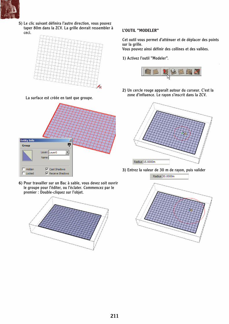
UN BAC À SABLE À PARTIR DE ZÉROAvec cet outil, vous allez créer uns surface plate (TIN) di-visée en grille. Cette surface pourra être modifiée à l'aide des autres outils du ac à sable.
1) Activez l'outil "à partir de zéro".
2) Dans le champs de la "Zone de contrôle des valeurs", entrez 5 (mètres)
3) Cliquez pour commencer à dessiner la grille et bougez la souris afin de tracer le premier côté, NE CLIQUEZ PAS TOUT DE SUITE. Les encoches mar-quent les 5 mètres.
2) Lorsque vous voulez utiliser les outils du Bac à sable, vous devez les activer. Ouvrez la fenêtre des préférences, puis dans "Extensions", cochez les outils "Bac à sable".
4) Utilisez la ZCV pour entrer la longueur exacte, tapez 100 et validez.
211
Google SketchUp 6: Advanced Exercises
176
5. The next click defines the other grid direction. Make it something like this:
The surface is created as a group, which is indicated by its Entity Info window.
6. To work on a sandbox, you must either open the group to edit it, or explode it. Do the first - double-click the group to edit it.
SmooveThe Smoove tool is a combination of smoothing and moving (but the name still sounds a bit weird). You can use it to sculpt a TIN - to make hills and valleys, or to smooth out areas that are too jagged or bumpy. By moving a circular area of a TIN up or down, you get a smooth deformation.1. Click Smoove, or select Tools / Sandbox / Smoove.
2. A red circle appears around the cursor - this is the tool’s area of influence. The radius of this circle is listed in the VCB.
3. Enter 30 to set a 30m radius circle.
L'OUTIL "MODELER"
Cet outil vous permet d'atténuer et de déplacer des points sur la grille.Vous pouvez ainsi définir des collines et des vallées.
1) Activez l'outil "Modeler".
2) Un cercle rouge apparaît autour du curseur. C'est la zone d'influence. Le rayon s'inscrit dans la ZCV.
3) Entrez la valeur de 30 m de rayon, puis valider
5) Le clic suivant définira l'autre direction, vous pouvez taper 80m dans la ZCV. La grille devrait ressembler à ceci.
6) Pour travailler sur un Bac à sable, vous devez soit ouvrir le groupe pour l'éditer, ou l'éclater. Commencez par le premier : Double-cliquez sur l'objet.
La surface est créée en tant que groupe.
SketchUp version 6.0 exercices
212
Sandbox Tools
177
4. You can place the center of the Smoove circle in one of several places. Click to place the center at a grid intersection point.
The grid points that will be affected (those within the circle radius) are highlighted by squares. The largest square is where you placed the circle center, and the squares get progressively smaller farther out.
5. You can move these grid points up or down. The Offset value is indicated; you can do it by eye or enter an exact value. Raise the center of this area about 10m upward.
6. For the next smoove, place the center at a grid edge.
The two largest squares are at both ends of this edge.
7. Pull this area up as well. You’ve now created two hills.
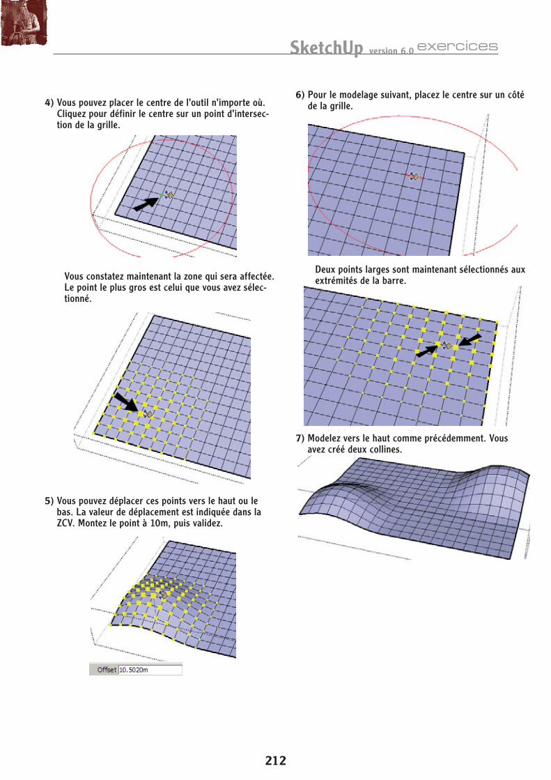
4) Vous pouvez placer le centre de l'outil n'importe où. Cliquez pour définir le centre sur un point d'intersec-tion de la grille.
5) Vous pouvez déplacer ces points vers le haut ou le bas. La valeur de déplacement est indiquée dans la ZCV. Montez le point à 10m, puis validez.
6) Pour le modelage suivant, placez le centre sur un côté de la grille.
7) Modelez vers le haut comme précédemment. Vous avez créé deux collines.
Deux points larges sont maintenant sélectionnés aux extrémités de la barre.Vous constatez maintenant la zone qui sera affectée.
Le point le plus gros est celui que vous avez sélec-tionné.
213
Google SketchUp 6: Advanced Exercises
178
8. Reduce the radius to 20m, and this time place the center on one of the hidden diagonal edges. Hidden edges appear when the cursor passes over them.
9. Again, the endpoints of the edge have the largest squares. And there are now fewer grid points affected.
10. Pull up one more small hill by placing the center on one of the triangular faces. These faces also appear when the cursor passes over them.
11. Reduce the radius once again to 10m. Create a few depressions in the center to simulate a lake bed.
From the side, your TIN should look something like this:
12. Display hidden geometry to see all edges that comprise the TIN. Each triangular face is flat, but all together they create a smooth look.
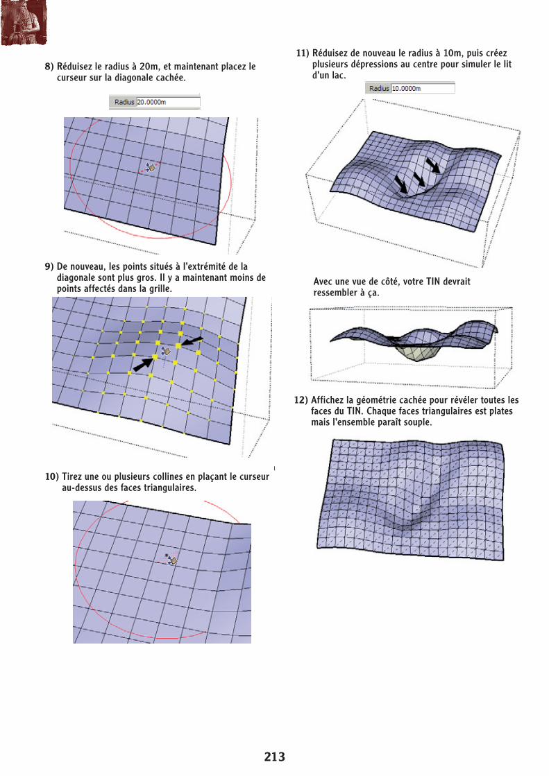
8) Réduisez le radius à 20m, et maintenant placez le curseur sur la diagonale cachée.
11) Réduisez de nouveau le radius à 10m, puis créez plusieurs dépressions au centre pour simuler le lit d'un lac.
12) Affichez la géométrie cachée pour révéler toutes les faces du TIN. Chaque faces triangulaires est plates mais l'ensemble paraît souple.
Avec une vue de côté, votre TIN devraitressembler à ça.
9) De nouveau, les points situés à l'extrémité de la diagonale sont plus gros. Il y a maintenant moins de points affectés dans la grille.
10) Tirez une ou plusieurs collines en plaçant le curseur au-dessus des faces triangulaires.
SketchUp version 6.0 exercices
214
Sandbox Tools
179
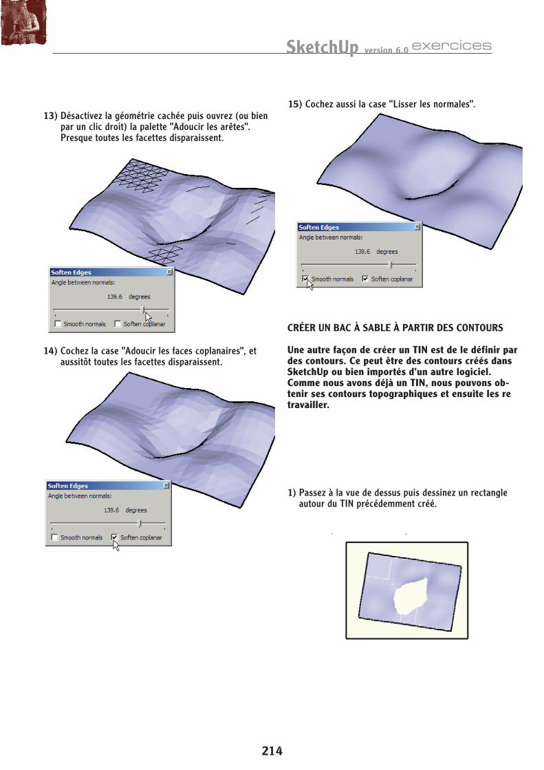
13. Turn off the hidden geometry, and open the SoftenEdges window (Window / Soften Edges, or select the entire TIN and right-click). Move the slider to the right to see the edges start to disappear. With nothing else checked, the surface has a faceted look.
14. Check Soften Coplanar, and edges along flat areas also disappear.
15. Check Smooth Normals to remove the faceting.
Sandbox from ContoursAnother way to create a TIN is to create it from contours you already have. These could be curves you create within Google SketchUp, or curves you import from another application.Because we already have a TIN surface from the previous exercises, we can get its topographical contours and then re-create the TIN.
NOTE: If you want to compare the From Contours TIN to the From Scratch one, make a copy of the TIN to work on, keeping the original.
If you want to download this set of contours, go to www.f1help.biz/ccp51/cgi-bin/SU6Files.htm and download the file “SandboxContours.skp.” You can then skip to Step 6.1. Switch to Top view and draw a rectangle around the
TIN you created in the previous exercise.
13) Désactivez la géométrie cachée puis ouvrez (ou bien par un clic droit) la palette "Adoucir les arêtes". Presque toutes les facettes disparaissent.
14) Cochez la case "Adoucir les faces coplanaires", et aussitôt toutes les facettes disparaissent.
15) Cochez aussi la case "Lisser les normales".
CRÉER UN BAC À SABLE À PARTIR DES CONTOURS
Une autre façon de créer un TIN est de le définir par des contours. Ce peut être des contours créés dans SketchUp ou bien importés d'un autre logiciel.Comme nous avons déjà un TIN, nous pouvons ob-tenir ses contours topographiques et ensuite les re travailler.
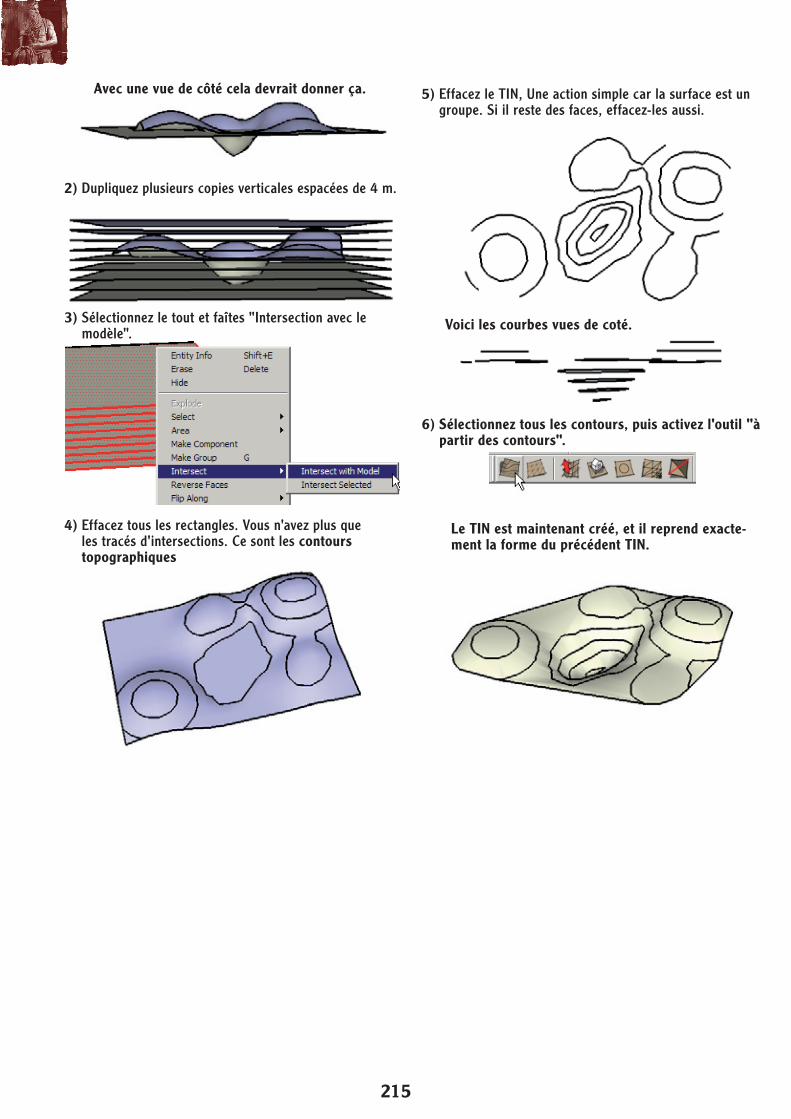
1) Passez à la vue de dessus puis dessinez un rectangle autour du TIN précédemment créé.
215
Google SketchUp 6: Advanced Exercises
180
From the side, it should look something like this:
2. Make vertical copies of this rectangle. In this example, the rectangle spacing is 4m.
3. Select all rectangles and run Intersect with Model.
4. Erase the rectangles, and you are left with the intersection edges. These are the topographical contours.
5. Erase the TIN (easily done since it should still be a group). Contours that are closed loops may contain faces - erase these as well.
Here are the curves from the side:
6. Select all contours, and click From Contours (Tools / Sandbox / From Contours).
The TIN is created, and it almost exactly matches the one you had created from scratch. The contour lines are thick because the TIN itself is a group, and the contour lines do not align to it.
NOTE: The resemblance would be identical if you had included the outer boundary of the original TIN in the group of contours. To do this, you would edit the TIN group and erase all but the four rectangular boundary curves. Then the group would have to be exploded.
2) Dupliquez plusieurs copies verticales espacées de 4 m.
5) Effacez le TIN, Une action simple car la surface est un groupe. Si il reste des faces, effacez-les aussi.
Voici les courbes vues de coté.
6) Sélectionnez tous les contours, puis activez l'outil "à partir des contours".
3) Sélectionnez le tout et faîtes "Intersection avec le modèle".
4) Effacez tous les rectangles. Vous n'avez plus que les tracés d'intersections. Ce sont les contours topographiques
Avec une vue de côté cela devrait donner ça.
Le TIN est maintenant créé, et il reprend exacte-ment la forme du précédent TIN.
SketchUp version 6.0 exercices
216
Sandbox Tools
181
7. Display the hidden edges. These are more complex that those of the From Scratch TIN.
8. Turn off hidden edges, and Explode the TIN (it may take a minute or so). Now the contour lines are thin.
Drape and StampDrape and Stamp are two tools that enable you to project objects onto a TIN. Drape projects boundary curves only, while Stamp pushes a 2D or 3D object into a TIN.We will continue working with the previous TIN model. If you want to download this TIN file, go to www.f1help.biz/ccp51/cgi-bin/SU6Files.htm and download the file “SandboxDrape.skp.”1. To create a lake at the bottom, connect any two points
on a contour near the bottom.
2. Erase any extra lines, and assign a different color (or water material) if you want.
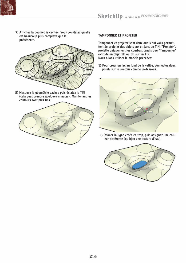
7) Affichez la géométrie cachée. Vous constatez qu'elle est beaucoup plus complexe que la précédente.
8) Masquez la géométrie cachée puis éclatez le TIN (cela peut prendre quelques minutes). Maintenant les contours sont plus fins.
2) Effacez la ligne créée en trop, puis assignez une cou-leur différente (ou bien une texture d'eau).
TAMPONNER ET PROJETER
Tamponner et projeter sont deux outils qui vous permet-tent de projeter des objets sur et dans un TIN. "Projeter", projette uniquement les courbes, tandis que "Tamponner" extrude un objet 2D ou 3D sur un TIN.Nous allons utiliser le modèle précédent
1) Pour créer un lac au fond de la vallée, connectez deux points sur le contour comme ci-dessous.
217
Google SketchUp 6: Advanced Exercises
182
3. The projection curves can now be created, and they will be placed on a flat rectangle. To prevent the rectangle from sticking to the TIN, make it a group.
4. Now create a flat rectangle that encloses the TIN.
5. Move the rectangle directly above the TIN.
6. Switch to Top view and turn off Perspective (select Camera / Parallel Projection). This is so you can create lines directly above the relevant points on the TIN, with no depth distortion. Switch to X-Raymode so that you can see the TIN through the rectangle.
7. We will create a line that represents the center of a roadway that will cross this terrain and the lake. If you click above a point on the TIN, the point will not be aligned to the rectangle, so first press Shift to lock the point to the rectangle face.
8. With Shift pressed, click a point directly above a point on one side of the lake.
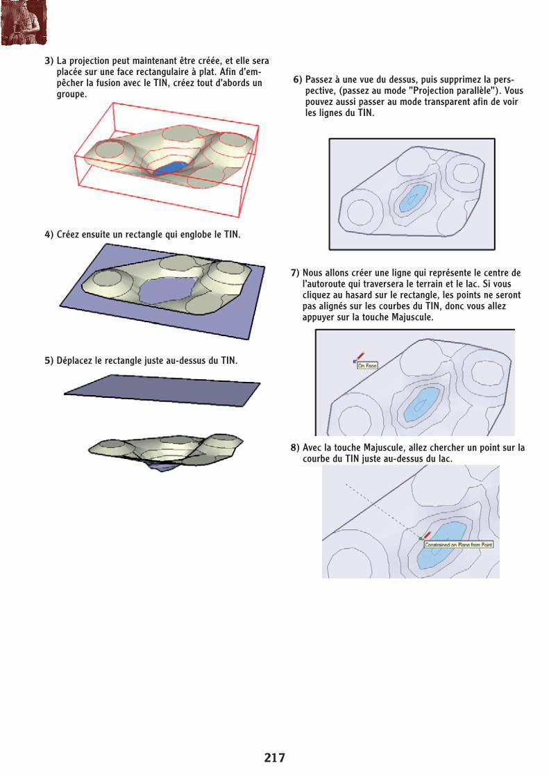
3) La projection peut maintenant être créée, et elle sera placée sur une face rectangulaire à plat. Afin d'em-pêcher la fusion avec le TIN, créez tout d'abords un groupe.
6) Passez à une vue du dessus, puis supprimez la pers-pective, (passez au mode "Projection parallèle"). Vous pouvez aussi passer au mode transparent afin de voir les lignes du TIN.
7) Nous allons créer une ligne qui représente le centre de l'autoroute qui traversera le terrain et le lac. Si vous cliquez au hasard sur le rectangle, les points ne seront pas alignés sur les courbes du TIN, donc vous allez appuyer sur la touche Majuscule.
8) Avec la touche Majuscule, allez chercher un point sur la courbe du TIN juste au-dessus du lac.
4) Créez ensuite un rectangle qui englobe le TIN.
5) Déplacez le rectangle juste au-dessus du TIN.
SketchUp version 6.0 exercices
218
Sandbox Tools
183
9. Do the same for a point on the other side of the lake.
10. Now complete the road line with two arcs on either side of the line.
11. Offset this set of curves 3m to either side. These are the roadway boundaries.
12. Erase the rectangle and roadway center lines, so that only the boundary lines remain.
13. To compare Drape and Stamp, make a copy of the entire model so far. Drape will be used on one, Stamp on the other.
Drape1. Select the roadway boundary curves - there should
be six total.2. Click Drape (Tools / Sandbox / Drape).
3. Click the TIN. Even though it is grouped, you can still select it as a whole (you could select it ungrouped as well).
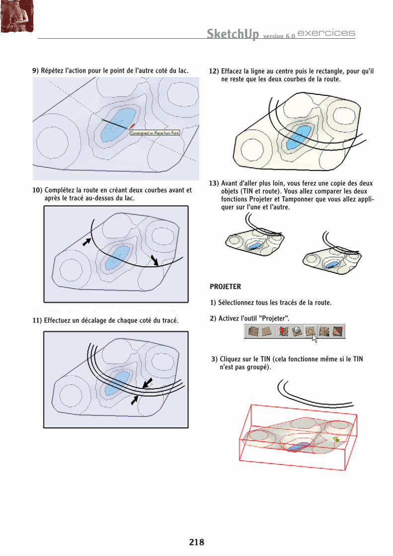
9) Répétez l'action pour le point de l'autre coté du lac. 12) Effacez la ligne au centre puis le rectangle, pour qu'il ne reste que les deux courbes de la route.
13) Avant d'aller plus loin, vous ferez une copie des deux objets (TIN et route). Vous allez comparer les deux fonctions Projeter et Tamponner que vous allez appli-quer sur l'une et l'autre.
10) Complétez la route en créant deux courbes avant et après le tracé au-dessus du lac.
11) Effectuez un décalage de chaque coté du tracé.
3) Cliquez sur le TIN (cela fonctionne même si le TIN n'est pas groupé).
PROJETER
1) Sélectionnez tous les tracés de la route.
2) Activez l'outil "Projeter".
219
Google SketchUp 6: Advanced Exercises
184
4. The roadway lines are projected onto the surface, and become part of the TIN group. (If you are still in X-Ray mode, you can see the roadway lines through the lake.)
5. Though it is not necessary for this simple model, the Text tool is handy for checking elevations. First, Explode the group. Then activate Text and click any point. The default text is the point’s coordinates, the last of which is the point’s elevation.
6. To create a bridge, draw lines between two sets of intersection points, all of which should have the same elevation.
7. Erase any extra lines, and apply colors if you want. Now you have a roadway over hilly terrain, with a bridge crossing the lake.
StampThis exercises uses the copy of the model you created earlier.1. This tool requires one or more 2D or 3D objects, but
you cannot select lines or curves. So add two lines between the open ends of the roadway.
2. Click Stamp (Tools / Sandbox / Stamp).
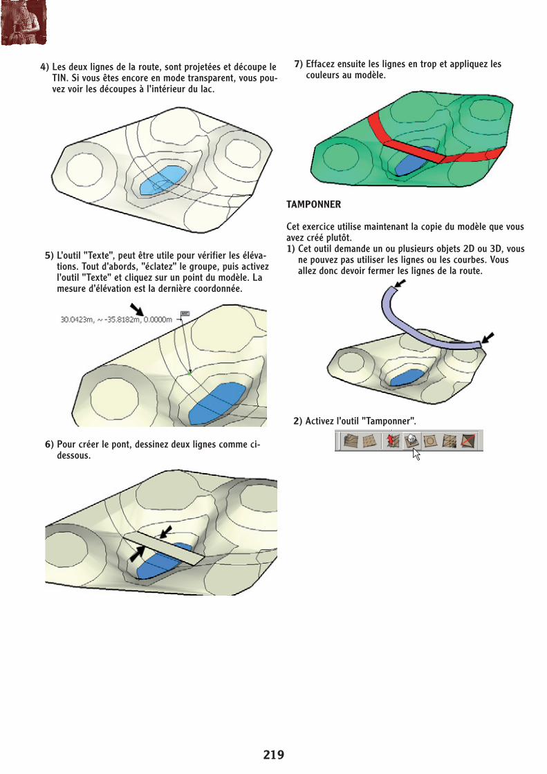
4) Les deux lignes de la route, sont projetées et découpe le TIN. Si vous êtes encore en mode transparent, vous pou-vez voir les découpes à l'intérieur du lac.
7) Effacez ensuite les lignes en trop et appliquez les couleurs au modèle.
5) L'outil "Texte", peut être utile pour vérifier les éléva-tions. Tout d'abords, "éclatez" le groupe, puis activez l'outil "Texte" et cliquez sur un point du modèle. La mesure d'élévation est la dernière coordonnée.
6) Pour créer le pont, dessinez deux lignes comme ci-dessous.
2) Activez l'outil "Tamponner".
TAMPONNER
Cet exercice utilise maintenant la copie du modèle que vous avez créé plutôt.1) Cet outil demande un ou plusieurs objets 2D ou 3D, vous
ne pouvez pas utiliser les lignes ou les courbes. Vous allez donc devoir fermer les lignes de la route.
SketchUp version 6.0 exercices
220
Sandbox Tools
185
3. Click the roadway face. A red offset line appears around the roadway face, and the offset distance is listed in the VCB. This is like the area of influence of the Smoove circle - it shows the area around the stamped object that will be added or removed from the TIN.
4. Enter 1.5 to set an offset like this:
5. Then click the TIN.
6. The roadway face can now cut through the TIN - move the cursor up and down to see how terrain material can be added or removed.
7. Place the roadway like this, so that it is above the lake but below the tops of the hills.
TIP: If there is a surface of the TIN you do not want to be affected by Stamp, such as the face of the lake, you can Groupit in advance.
All the new material on either side of the road above the lake should be removed. Here’s a way to do it that involves creating vertical abutment faces. In this example, color was added to match the previous example.
8. Explode the TIN.
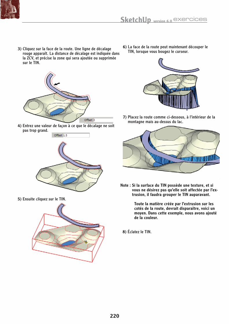
3) Cliquez sur la face de la route. Une ligne de décalage rouge apparaît. La distance de décalage est indiquée dans la ZCV, et précise la zone qui sera ajoutée ou supprimée sur le TIN.
6) La face de la route peut maintenant découper le TIN, lorsque vous bougez le curseur.
7) Placez la route comme ci-dessous, à l'intérieur de la montagne mais au-dessus du lac.
8) Éclatez le TIN.
Note : Si la surface du TIN possède une texture, et si vous ne désirez pas qu'elle soit affectée par l'ex-trusion, il faudra grouper le TIN auparavant.
Toute la matière créée par l'extrusion sur les cotés de la route, devrait disparaître, voici un moyen. Dans cette exemple, nous avons ajouté de la couleur.
4) Entrez une valeur de façon à ce que le décalage ne soit pas trop grand.
5) Ensuite cliquez sur le TIN.
221
Google SketchUp 6: Advanced Exercises
186
9. Start at the intersection of the added terrain and the lake surface. Draw a line straight up, stopping at the level of the roadway.
10. Draw a similar line on the other side.
11. Connect both sets of endpoints of these two vertical lines with horizontal lines. This creates the abutment face.
12. Create a similar face for the other side of the lake.
13. Select both faces and run Intersect with Model. You can then erase all material between the abutments.
Stamp in 3DThe Stamp tool can be used on one or more objects of any shape - 2D or 3D. This exercises shows a very simple example of this.1. Start with a basic grid using From Scratch.
2. Above the grid, make a vertical arc.
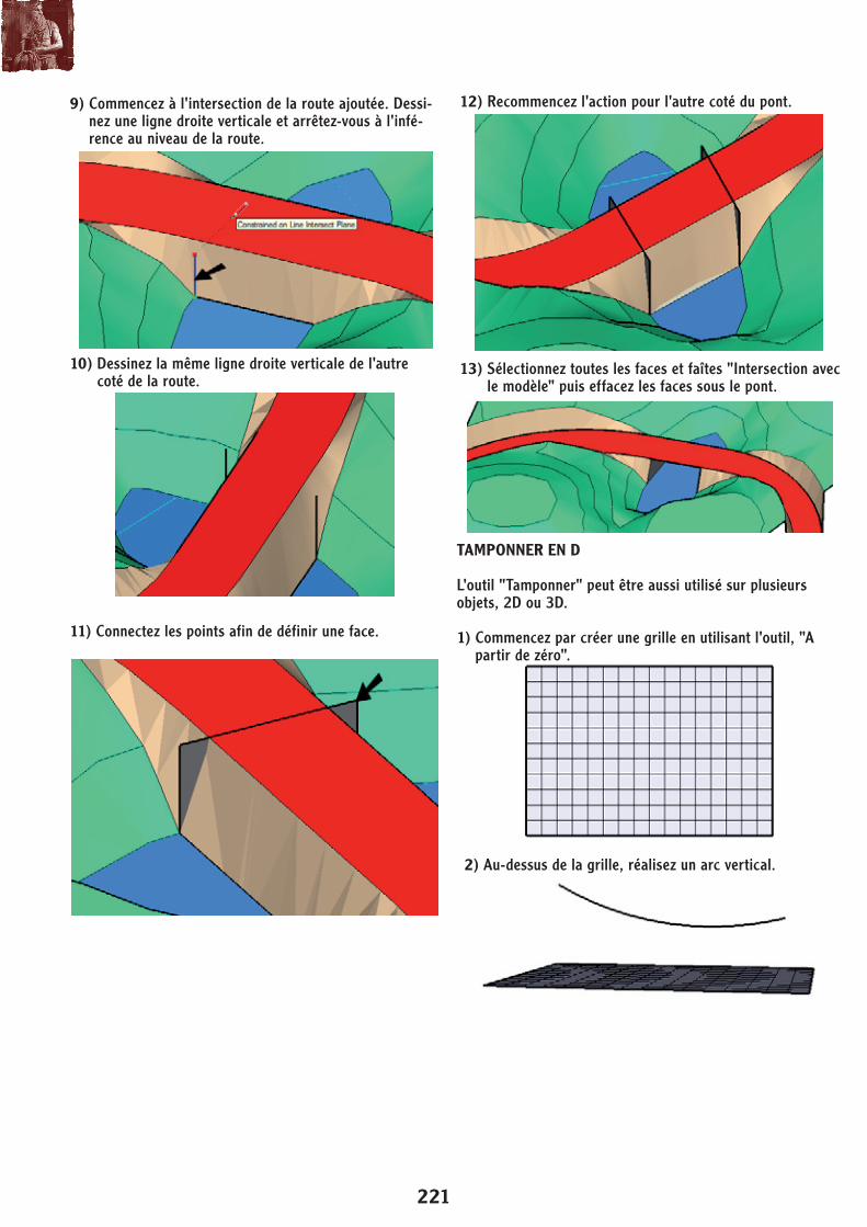
9) Commencez à l'intersection de la route ajoutée. Dessi-nez une ligne droite verticale et arrêtez-vous à l'infé-rence au niveau de la route.
10) Dessinez la même ligne droite verticale de l'autre coté de la route.
12) Recommencez l'action pour l'autre coté du pont.
13) Sélectionnez toutes les faces et faîtes "Intersection avec le modèle" puis effacez les faces sous le pont.
11) Connectez les points afin de définir une face.
2) Au-dessus de la grille, réalisez un arc vertical.
TAMPONNER EN D
L'outil "Tamponner" peut être aussi utilisé sur plusieurs objets, 2D ou 3D.
1) Commencez par créer une grille en utilisant l'outil, "A partir de zéro".
SketchUp version 6.0 exercices
222
Sandbox Tools
187
3. Place a small vertical circle at one of the arc, and use Scale to squash it into an oval.
4. Use Follow Me to drive the oval along the arc.
5. Select the oval tube (for lack of a better term) and activate Stamp. Set the offset something like this:
6. Push it down into the TIN. It creates something like a concave ramp within the grid, good for skateboarding!
Adding Detail to a SandboxThe Add Detail and Flip Edge tools enable you to make detailed changes to a TIN surface.If you want to download the TIN surface used in this exercise, go to www.f1help.biz/ccp51/cgi-bin/SU6Files.htm and get the file “SandboxDetailing.skp.” You can then skip to Step 5.1. Start in Top view and use Freehand to sketch some
terrain curves.
2. To make a bumpy (though not very realistic) surface, some of the curves will be moved vertically. Select alternating curves. . .
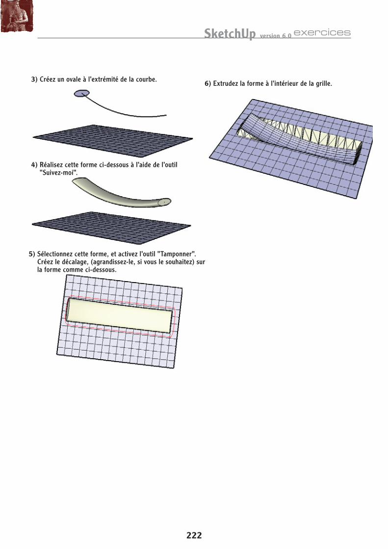
3) Créez un ovale à l'extrémité de la courbe.
4) Réalisez cette forme ci-dessous à l'aide de l'outil "Suivez-moi".
5) Sélectionnez cette forme, et activez l'outil "Tamponner". Créez le décalage, (agrandissez-le, si vous le souhaitez) sur la forme comme ci-dessous.
6) Extrudez la forme à l'intérieur de la grille.