Embed Size (px)
Citation preview
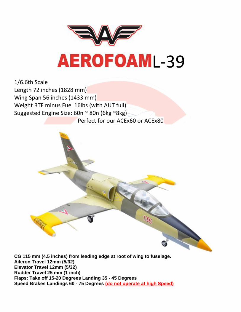
L-39
1/6.6th Scale Length 72 inches (1828 mm) Wing Span 56 inches (1433 mm) Weight RTF minus Fuel 16lbs (with AUT full) Suggested Engine Size: 60n ~ 80n (6kg ~8kg)
Perfect for our ACEx60 or ACEx80
CG 115 mm (4.5 inches) from leading edge at root of wing to fuselage. Aileron Travel 12mm (5/32) Elevator Travel 12mm (5/32) Rudder Travel 25 mm (1 inch) Flaps: Take off 15-20 Degrees Landing 35 - 45 Degrees Speed Brakes Landings 60 - 75 Degrees (do not operate at high Speed)
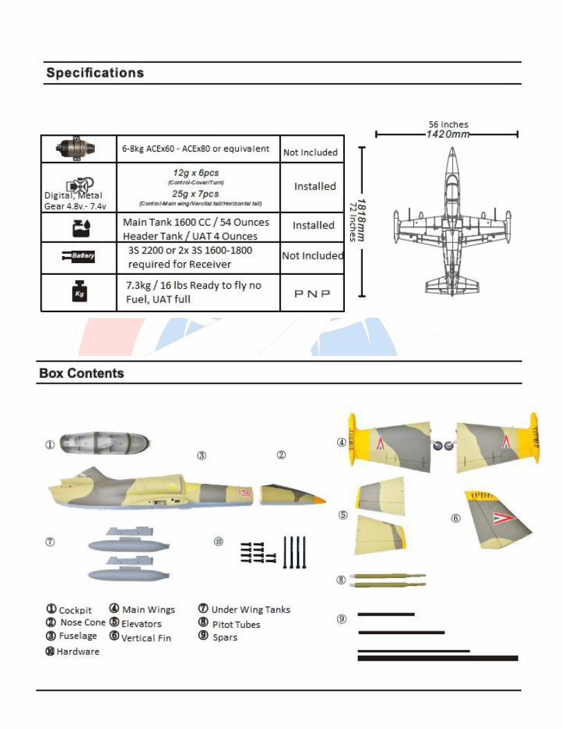
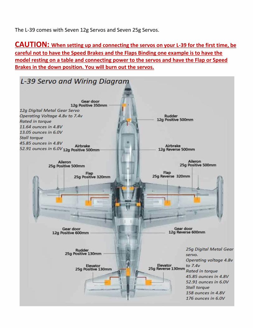
The L-39 comes with Seven 12g Servos and Seven 25g Servos.
CAUTION: When setting up and connecting the servos on your L-39 for the first time, be
careful not to have the Speed Brakes and the Flaps Binding one example is to have the model resting on a table and connecting power to the servos and have the Flap or Speed Brakes in the down position. You will burn out the servos.
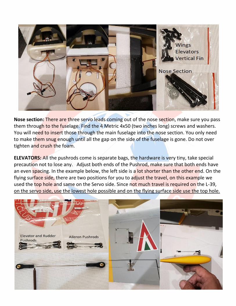
Nose section: There are three servo leads coming out of the nose section, make sure you pass them through to the fuselage. Find the 4 Metric 4x50 (two inches long) screws and washers. You will need to insert those through the main fuselage into the nose section. You only need to make them snug enough until all the gap on the side of the fuselage is gone. Do not over tighten and crush the foam.
ELEVATORS: All the pushrods come is separate bags, the hardware is very tiny, take special precaution not to lose any. Adjust both ends of the Pushrod, make sure that both ends have an even spacing. In the example below, the left side is a lot shorter than the other end. On the flying surface side, there are two positions for you to adjust the travel, on this example we used the top hole and same on the Servo side. Since not much travel is required on the L-39, on the servo side, use the lowest hole possible and on the flying surface side use the top hole.
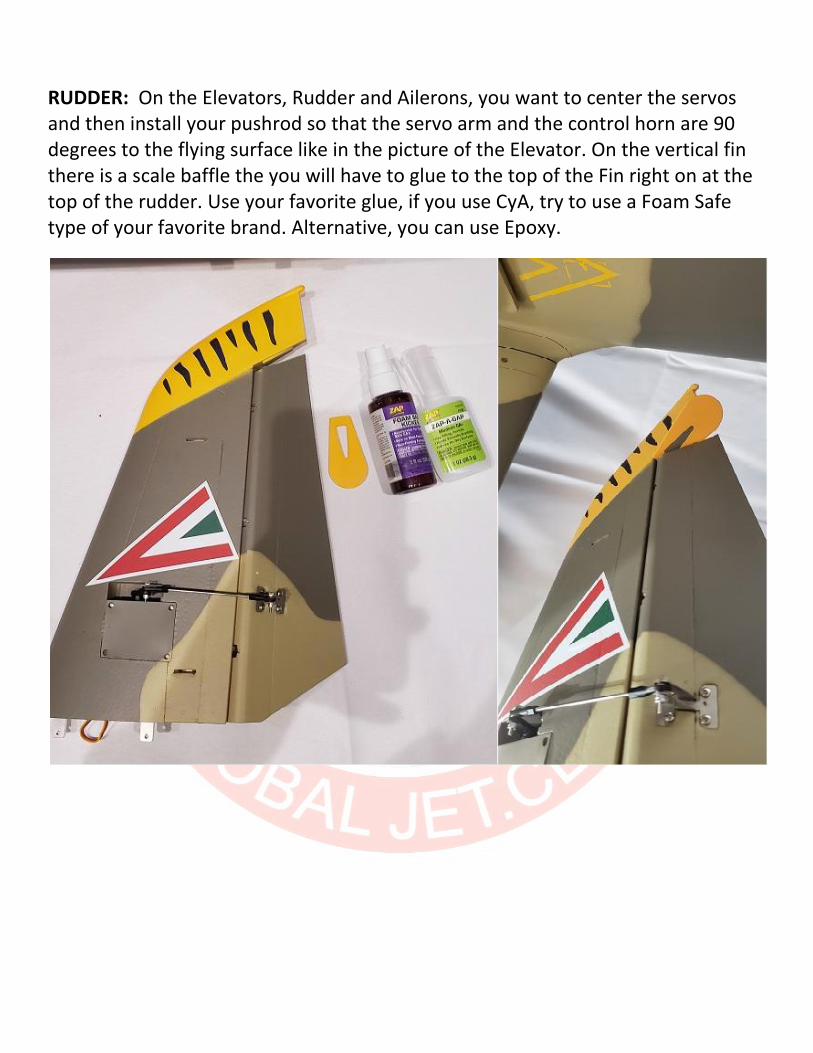
RUDDER: On the Elevators, Rudder and Ailerons, you want to center the servos and then install your pushrod so that the servo arm and the control horn are 90 degrees to the flying surface like in the picture of the Elevator. On the vertical fin there is a scale baffle the you will have to glue to the top of the Fin right on at the top of the rudder. Use your favorite glue, if you use CyA, try to use a Foam Safe type of your favorite brand. Alternative, you can use Epoxy.
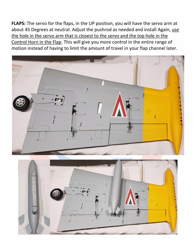
FLAPS: The servo for the flaps, in the UP position, you will have the servo arm at about 45 Degrees at neutral. Adjust the pushrod as needed and install Again, use the hole in the servo arm that is closest to the servo and the top hole in the Control Horn in the Flap. This will give you more control in the entire range of motion instead of having to limit the amount of travel in your flap channel later.
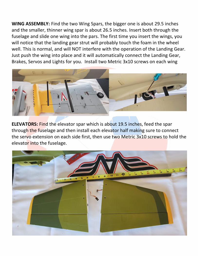
WING ASSEMBLY: Find the two Wing Spars, the bigger one is about 29.5 inches and the smaller, thinner wing spar is about 26.5 inches. Insert both through the fuselage and slide one wing into the pars. The first time you insert the wings, you will notice that the landing gear strut will probably touch the foam in the wheel well. This is normal, and will NOT interfere with the operation of the Landing Gear. Just push the wing into place and it will automatically connect the Landing Gear, Brakes, Servos and Lights for you. Install two Metric 3x10 screws on each wing
ELEVATORS: Find the elevator spar which is about 19.5 inches, feed the spar through the fuselage and then install each elevator half making sure to connect the servo extension on each side first, then use two Metric 3x10 screws to hold the elevator into the fuselage.
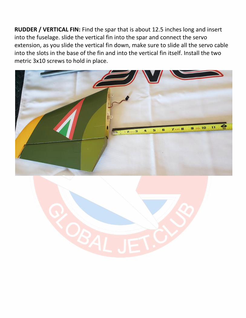
RUDDER / VERTICAL FIN: Find the spar that is about 12.5 inches long and insert into the fuselage. slide the vertical fin into the spar and connect the servo extension, as you slide the vertical fin down, make sure to slide all the servo cable into the slots in the base of the fin and into the vertical fin itself. Install the two metric 3x10 screws to hold in place.
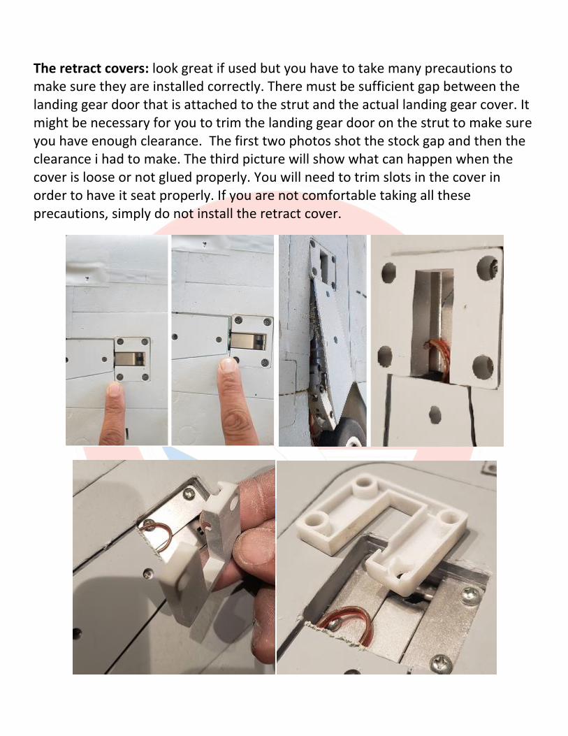
The retract covers: look great if used but you have to take many precautions to make sure they are installed correctly. There must be sufficient gap between the landing gear door that is attached to the strut and the actual landing gear cover. It might be necessary for you to trim the landing gear door on the strut to make sure you have enough clearance. The first two photos shot the stock gap and then the clearance i had to make. The third picture will show what can happen when the cover is loose or not glued properly. You will need to trim slots in the cover in order to have it seat properly. If you are not comfortable taking all these precautions, simply do not install the retract cover.
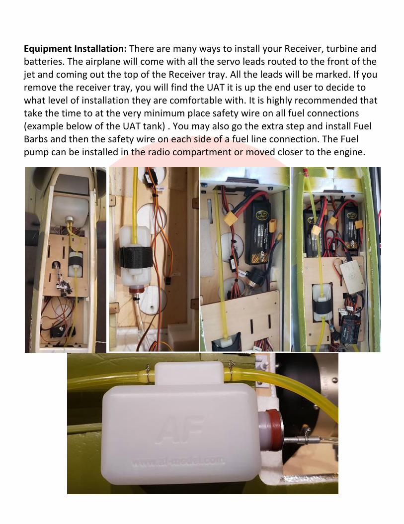
Equipment Installation: There are many ways to install your Receiver, turbine and batteries. The airplane will come with all the servo leads routed to the front of the jet and coming out the top of the Receiver tray. All the leads will be marked. If you remove the receiver tray, you will find the UAT it is up the end user to decide to what level of installation they are comfortable with. It is highly recommended that take the time to at the very minimum place safety wire on all fuel connections (example below of the UAT tank) . You may also go the extra step and install Fuel Barbs and then the safety wire on each side of a fuel line connection. The Fuel pump can be installed in the radio compartment or moved closer to the engine.
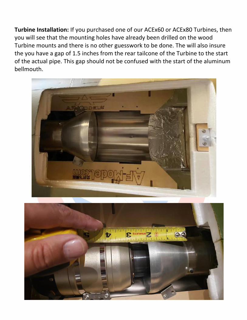
Turbine Installation: If you purchased one of our ACEx60 or ACEx80 Turbines, then you will see that the mounting holes have already been drilled on the wood Turbine mounts and there is no other guesswork to be done. The will also insure the you have a gap of 1.5 inches from the rear tailcone of the Turbine to the start of the actual pipe. This gap should not be confused with the start of the aluminum bellmouth.
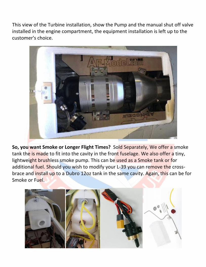
This view of the Turbine installation, show the Pump and the manual shut off valve installed in the engine compartment, the equipment installation is left up to the customer's choice.
So, you want Smoke or Longer Flight Times? Sold Separately, We offer a smoke tank the is made to fit into the cavity in the front fuselage. We also offer a tiny, lightweight brushless smoke pump. This can be used as a Smoke tank or for additional fuel. Should you wish to modify your L-39 you can remove the cross-brace and install up to a Dubro 12oz tank in the same cavity. Again, this can be for Smoke or Fuel.
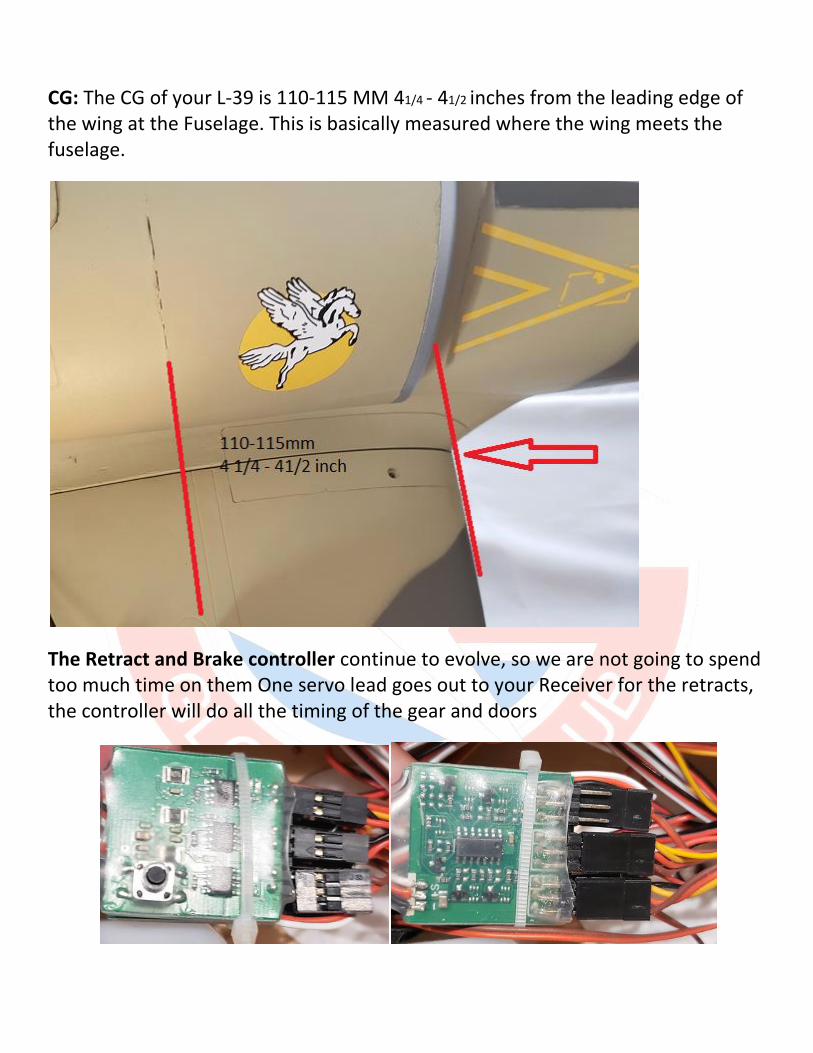
CG: The CG of your L-39 is 110-115 MM 41/4 - 41/2 inches from the leading edge of the wing at the Fuselage. This is basically measured where the wing meets the fuselage.
The Retract and Brake controller continue to evolve, so we are not going to spend too much time on them One servo lead goes out to your Receiver for the retracts, the controller will do all the timing of the gear and doors

The Aerofoam L-39 is available from:
(626) 629-8552 https://www.bananahobby.com [email protected]
https://globaljet.club/ Phone 1-888-573-3883 1-702-582-9635 Email [email protected] Address Irvine, CA 92612
0049 5624-922486 www.final-modellbau.de [email protected]


![Catalog C-002 Rev. B · 1] ±0.001 inches [0.03 mm] for male contact mating diameters. 2] ±0.003 inches [0.08 mm] for contact termination diameters. 3] ±0.005 inches [0.13 mm] for](https://img.pdfslide.us/doc/110x75/5fb5a758af199938f61750b5/catalog-c-002-rev-b-1-0001-inches-003-mm-for-male-contact-mating-diameters.jpg)