Embed Size (px)
Citation preview
Left Engine Failure and Subsequent Depressurization Southwest Airlines Flight 1380
Boeing 737-7H4, N772SW Philadelphia, Pennsylvania
April 17, 2018
Accident Report NTSB/AAR-19/03
PB2019-101439
National Transportation Safety Board

NTSB/AAR-19/03 PB2019-101439 Notation 59687
Adopted November 19, 2019
Aircraft Accident Report Left Engine Failure and Subsequent Depressurization
Southwest Airlines Flight 1380 Boeing 737-7H4, N772SW Philadelphia, Pennsylvania
April 17, 2018
National Transportation Safety Board
490 L’Enfant Plaza, S.W. Washington, D.C. 20594
National Transportation Safety Board. 2019. Left Engine Failure and Subsequent Depressurization, Southwest Airlines Flight 1380, Boeing 737-7H4, N772SW, Philadelphia, Pennsylvania, April 17, 2018. Aircraft Accident Report NTSB/AAR-19/03. Washington, DC. Abstract: This report discusses the April 17, 2018, accident involving a Boeing 737-7H4, N772SW, operated by Southwest Airlines as flight 1380, that experienced a failure of its left CFM International CFM56-7B turbofan engine while climbing through flight level 320 en route to the flight’s assigned cruise altitude (the flight had departed from LaGuardia Airport, Queens, New York, about 30 minutes earlier). Portions of the left engine inlet and fan cowl separated from the airplane; one fan cowl fragment impacted the left-side fuselage near a cabin window, and the window departed the airplane, which resulted in a rapid depressurization. As a result of the engine failure, the flight crew conducted an emergency descent and diverted to Philadelphia International Airport (PHL), Philadelphia, Pennsylvania. The airplane landed safely at PHL about 17 minutes after the engine failure occurred. Of the 144 passengers and 5 crewmembers aboard the airplane, 1 passenger received fatal injuries, and 8 passengers received minor injuries. Safety issues identified in this report include the need to ensure the structural integrity of the fan cowl on Boeing 737 next-generation-series airplanes after a fan-blade-out event involving CFM56 7B engines, the need to determine whether other airframe/engine combinations have any critical fan blade impact locations and how an impact at those locations could affect nacelle components, the need to emphasize the importance of having flight attendants secured in a jumpseat during emergency landings, and the need to mitigate hazards to passengers affected by an in-flight loss of seating capacity. As a result of this investigation, the National Transportation Safety Board makes five new safety recommendations to the Federal Aviation Administration and one new recommendation each to Southwest Airlines and the European Aviation Safety Agency. The National Transportation Safety Board (NTSB) is an independent federal agency dedicated to promoting aviation, railroad, highway, marine, and pipeline safety. Established in 1967, the agency is mandated by Congress through the Independent Safety Board Act of 1974 to investigate transportation accidents, determine the probable causes of the accidents, issue safety recommendations, study transportation safety issues, and evaluate the safety effectiveness of government agencies involved in transportation. The NTSB makes public its actions and decisions through accident reports, safety studies, special investigation reports, safety recommendations, and statistical reviews. The NTSB does not assign fault or blame for an accident or incident; rather, as specified by NTSB regulation, “accident/incident investigations are fact-finding proceedings with no formal issues and no adverse parties … and are not conducted for the purpose of determining the rights or liabilities of any person.” 49 C.F.R. § 831.4. Assignment of fault or legal liability is not relevant to the NTSB’s statutory mission to improve transportation safety by investigating accidents and incidents and issuing safety recommendations. In addition, statutory language prohibits the admission into evidence or use of any part of an NTSB report related to an accident in a civil action for damages resulting from a matter mentioned in the report. 49 U.S.C. § 1154(b). For more detailed background information on this report, visit http://www.ntsb.gov/investigations/dms.html and search for NTSB accident ID DCA18MA142. Recent publications are available in their entirety on the Internet at http://www.ntsb.gov. Other information about available publications also may be obtained from the website or by contacting: National Transportation Safety Board Records Management Division, CIO-40 490 L’Enfant Plaza, SW Washington, DC 20594 (800) 877-6799 or (202) 314-6551 NTSB publications may be purchased from the National Technical Information Service. To purchase this publication, order product number PB2019-101439 from: National Technical Information Service 5301 Shawnee Rd. Alexandria, VA 22312 (800) 553-6847 or (703) 605-6000 http://www.ntis.gov/
NTSB Aircraft Accident Report
i
Contents Figures ........................................................................................................................................... iv
Tables ..............................................................................................................................................v
Abbreviations ............................................................................................................................... vi
Executive Summary ................................................................................................................... viii Probable Cause............................................................................................................................... ix Safety Issues.....................................................................................................................................x Findings.......................................................................................................................................... xi Recommendations ......................................................................................................................... xii
1. Factual Information ...................................................................................................................1 1.1 History of Flight .........................................................................................................................1
1.1.1 Events After Landing .......................................................................................................6 1.2 Personnel Information ................................................................................................................7
1.2.1 The Captain ......................................................................................................................7 1.2.2 The First Officer ..............................................................................................................8 1.2.3 The Flight Attendants ......................................................................................................9
1.3 Airplane Information .................................................................................................................9 1.3.1 Engine ............................................................................................................................11 1.3.2 Inlet ................................................................................................................................14 1.3.3 Fan Cowl ........................................................................................................................16 1.3.4 Postaccident Examinations ............................................................................................18
1.3.4.1 Engine ..............................................................................................................19 1.3.4.2 Inlet ..................................................................................................................20 1.3.4.3 Fan Cowl ..........................................................................................................22
1.3.5 Certification of Engine and Airframe Components .......................................................24 1.3.5.1 Engine Certification Regulations .....................................................................25 1.3.5.2 Tests for Engine Certification ..........................................................................26 1.3.5.3 Airplane Certification Regulations ..................................................................28 1.3.5.4 Inlet and Fan Cowl Fan-Blade-Out Structural Analysis ..................................30
1.3.6 Accident Sequence .........................................................................................................31 1.3.6.1 Overview ..........................................................................................................31 1.3.6.2 Accident Events Compared with Certification Activities ................................32
1.3.7 Postaccident Inlet and Fan Cowl Structural Analyses ...................................................34 1.3.7.1 Fan-Blade-Out Event Phases ...........................................................................34 1.3.7.2 Inlet Failure Sequence......................................................................................35 1.3.7.3 Fan Cowl Failure Sequence .............................................................................37
1.4 Meteorological Information .....................................................................................................39 1.5 Airport Information ..................................................................................................................39 1.6 Flight Recorders .......................................................................................................................40
NTSB Aircraft Accident Report
ii
1.7 Survival Aspects ......................................................................................................................40 1.7.1 Cabin Window ...............................................................................................................40 1.7.2 Cabin Pressurization Control System ............................................................................42 1.7.3 Supplemental Oxygen System .......................................................................................43 1.7.4 Flight Attendant Postaccident Interviews ......................................................................43
1.8 Tests and Research ...................................................................................................................45 1.8.1 Metallurgical Examinations ...........................................................................................45 1.8.2 Timeline Study ...............................................................................................................50
1.9 Organizational Information—Southwest Airlines ...................................................................51 1.9.1 Flight Manuals and Checklists.......................................................................................51
1.9.1.1 Engine Fire or Engine Severe Damage or Separation .....................................52 1.9.1.2 One Engine Inoperative Landing .....................................................................54 1.9.1.3 Cabin Altitude Warning or Rapid Depressurization ........................................54 1.9.1.4 Emergency Descent .........................................................................................55 1.9.1.5 Before Landing ................................................................................................56
1.9.2 Flight Crew Training .....................................................................................................57 1.9.3 Flight Attendant Manual ................................................................................................57 1.9.4 Flight Attendant Training ..............................................................................................59
1.10 Additional Information ..........................................................................................................60 1.10.1 Previous Fan-Blade-Out Accident ...............................................................................60 1.10.2 Service Bulletins and Airworthiness Directives ..........................................................61
1.10.2.1 CFM SB 72-1019 ...........................................................................................62 1.10.2.2 CFM SB 72-1024 ...........................................................................................64 1.10.2.3 CFM SB 72-1033 ...........................................................................................64 1.10.2.4 CFM SB 72-1050 ...........................................................................................65 1.10.2.5 FAA Emergency AD 2018-09-51 ..................................................................65 1.10.2.6 FAA ADs 2018-09-10, 2018-10-11, 2018-18-01, and 2018-26-01 ...............66 1.10.2.7 EASA Emergency AD 2018-0093-E .............................................................67 1.10.2.8 EASA ADs 2018-0109, 2018-0211, and 2019-0018 .....................................67
1.10.3 CFM56-7B Fan Blade Inspections ..............................................................................68
2. Analysis .....................................................................................................................................70 2.1 Introduction ..............................................................................................................................70 2.2 Accident Summary...................................................................................................................71
2.2.1 Fan Blade Release ..........................................................................................................71 2.2.2 Inlet Departure ...............................................................................................................73 2.2.3 Fan Cowl Departure .......................................................................................................75
2.3 Certification Summary .............................................................................................................80 2.4 Operational Factors ..................................................................................................................81
2.4.1 Checklist Performance ...................................................................................................81 2.4.2 Emergency Landing Airport Selection ..........................................................................85
2.5 Occupant Safety During Emergency Landings........................................................................86
3. Conclusions ...............................................................................................................................89 3.1 Findings....................................................................................................................................89 3.2 Probable Cause.........................................................................................................................90
NTSB Aircraft Accident Report
iii
4. Recommendations ....................................................................................................................91
5. Appendixes................................................................................................................................93 Appendix A: Investigation and Hearing ........................................................................................93 Appendix B: Cockpit Voice Recorder Transcript ..........................................................................94
References ...................................................................................................................................177
NTSB Aircraft Accident Report
iv
Figures Figure 1. Locations of engine, inlet, and fan cowl. .......................................................................10
Figure 2. Fan assembly. ................................................................................................................12
Figure 3. Cross-section of engine and airframe components. .......................................................13
Figure 4. Inlet cross-section. .........................................................................................................16
Figure 5. Left engine fan cowl. .....................................................................................................17
Figure 6. Lower aft corner of inboard fan cowl aligned with witness marks on fuselage. ...........19
Figure 7. Fatigue indications on fan blade fracture surface. .........................................................20
Figure 8. Inlet damage. .................................................................................................................21
Figure 9. Inboard fan cowl damage. .............................................................................................23
Figure 10. Radial restraint bracket damage. .................................................................................24
Figure 11. General example of a helix angle. ...............................................................................27
Figure 12. Fan blade fragment exit trajectories. ...........................................................................33
Figure 13. Predicted inlet failure sequence. ..................................................................................37
Figure 14. Predicted fan cowl failure sequence. ...........................................................................38
Figure 15. Window by seat 14A after the accident and window dimensions. ..............................41
Figure 16. Crack arrest lines and ratchet marks in fatigue origin area. ........................................46
Figure 17. Engine Fire or Engine Severe Damage or Separation checklist. .................................53
Figure 18. First page of One Engine Inoperative Landing checklist. ...........................................54
Figure 19. First page of Cabin Altitude Warning or Rapid Depressurization checklist. ..............55
Figure 20. Emergency Descent checklist. .....................................................................................56
Figure 21. Location of the radial restraint fitting on the fan cowl and in relation to the fan case. ....................................................................................................................................76
Figure 22. Trajectory of the inboard aft latch keeper during the accident sequence. ...................78
NTSB Aircraft Accident Report
v
Tables Table 1. FBO event timeline. ........................................................................................................35
Table 2. Predicted inlet failure timeline. .......................................................................................36
Table 3. Predicted fan cowl failure timeline. ................................................................................38
Table 4. Fan blade cracks detected after the SWA flight 1380 accident (as of June 2018). .........50
Table 5. Timeline for events related to cabin depressurization.....................................................51
Table 6. Fan blade cracks on SWA flight 3472 accident engine. .................................................61
Table 7. CFM, FAA, and EASA documents regarding CFM56-7B fan blade dovetail inspections. .......................................................................................................................61
NTSB Aircraft Accident Report
vi
Abbreviations AC advisory circular
AD airworthiness directive
AED automated external defibrillator
agl above ground level
APU auxiliary power unit
ARFF aircraft rescue and firefighting
ASOS automated surface observing system
ATC air traffic control
BEA Bureau d’Enquêtes et d’Analyses pour la Sécurité de l’Aviation Civile
BNA Nashville International Airport
CDT central daylight time
CFR Code of Federal Regulations
CVR cockpit voice recorder
DGAC Direction Générale de L’Aviation Civile
EASA European Aviation Safety Agency
ECI eddy current inspection
ESN engine serial number
FAA Federal Aviation Administration
FBO fan blade out
FDR flight data recorder
FPI fluorescent penetrant inspection
GE General Electric
NTSB Aircraft Accident Report
vii
HOU William P. Hobby Airport
HPC high-pressure compressor
HPT high-pressure turbine
LGA LaGuardia Airport
LOE line operational evaluation
LPT low-pressure turbine
MDT Harrisburg International Airport
NG next generation
nm nautical mile
NPRM notice of proposed rulemaking
NTSB National Transportation Safety Board
PA public address
PHL Philadelphia International Airport
PNS Pensacola International Airport
PTI Propulsion Technologies International
QRC quick reference card
QRH quick reference handbook
SB service bulletin
SEM scanning electron microscope
SWA Southwest Airlines
UTAS UTC Aerospace Systems
VMO maximum operating speed
NTSB Aircraft Accident Report
viii
Executive Summary On April 17, 2018, about 1103 eastern daylight time, Southwest Airlines (SWA)
flight 1380, a Boeing 737-7H4, N772SW, experienced a left engine failure while climbing through flight level 320 en route to the flight’s assigned cruise altitude. The flight had departed from LaGuardia Airport, Queens, New York, about 30 minutes earlier. As a result of the engine failure, the flight crew conducted an emergency descent and diverted to Philadelphia International Airport (PHL), Philadelphia, Pennsylvania. Portions of the left engine inlet and fan cowl separated from the airplane, and fragments from the inlet and fan cowl struck the left wing, the left-side fuselage, and the left horizontal stabilizer. One fan cowl fragment impacted the left-side fuselage near a cabin window, and the window departed the airplane, which resulted in a rapid depressurization. The airplane landed safely at PHL about 17 minutes after the engine failure occurred. Of the 144 passengers and 5 crewmembers aboard the airplane, 1 passenger received fatal injuries, and 8 passengers received minor injuries. The airplane was substantially damaged. The regularly scheduled domestic passenger flight was operating under the provisions of Title 14 Code of Federal Regulations (CFR) Part 121 with a destination of Dallas Love Field, Dallas, Texas.1
The airplane was equipped with two CFM International CFM56-7B24 turbofan engines. The CFM56-7B engine has 24 fan blades installed in the fan disk. The left engine failure occurred when one of the fan blades fractured at its root (referred to as a fan-blade-out [FBO] event). The fan blade fractured due to a low-cycle fatigue crack that initiated in the dovetail (part of the blade root), which remained within a slot of the fan disk.
The separated fan blade impacted the engine fan case and fractured into multiple fragments. Some of the fan blade fragments traveled forward of the engine and into the inlet.2 In addition, the fan blade’s impact with the fan case caused the fan case to deform locally over a short period of time. This deformation traveled both around and forward/aft of the fan case. After reaching the airplane structure (the inlet attach ring, which was secured to the engine fan case A1 flange), the deformation generated large loads that resulted in local damage to the inlet. The forward-traveling fan blade fragments and the deformation compromised the structural integrity of the inlet, causing portions of the inlet to depart the airplane.
The impact of the separated fan blade with the fan case also imparted significant loads into the fan cowl (also part of the nacelle) through the radial restraint fitting, which was located at the bottom of the inboard fan cowl.3 These loads caused cracks to form in the fan cowl skin and frames near the radial restraint fitting. This damage then propagated forward and aft, severing the three
1 For more information, see the factual information and analysis sections of this report. Additional
information can be found in the public docket for this National Transportation Safety Board accident investigation (case number DCA18MA142) by accessing the Accident Dockets link at www.ntsb.gov. For information about our safety recommendations, see the Safety Recommendation Database at the same website.
2 The inlet is part of the nacelle, which is the airplane structure that houses the engine. 3 The 737-700 is one of four Boeing 737 next-generation (NG) airplane models. (The NG-series of Boeing 737
airplanes also includes the 737-600, -800, and -900.) Boeing 737NG-series airplanes have an asymmetric fan cowl and a flat-bottom nacelle to accommodate the requirements of the CFM56-7B engine. The radial restraint fitting on the fan cowl engages with a radial restraint bracket on the engine fan case to help the fan cowl maintain its shape.
NTSB Aircraft Accident Report
ix
latch assemblies that joined the inboard and outboard halves of the fan cowl, which caused large portions of both fan cowl halves to separate and depart the airplane. One fan cowl part that was recovered after the accident was the inboard fan cowl aft latch keeper. The left side of the fuselage near the location of the missing cabin window (row 14) had impact damage and witness marks that were consistent with the size and shape of the inboard fan cowl aft latch keeper and surrounding structure.
During the accident sequence, the fan blade fragments traveling forward of the fan case had a trajectory angle that was greater than that observed during the CFM56-7B engine FBO containment certification tests. Also, the inlet damage caused by the forward-traveling fan blade fragments was greater than that observed during the engine FBO containment certification tests and accounted for in Boeing’s 737-700 certification analyses (which used the state-of-the-art analytical modeling tools that were available at the time). In addition, FBO-generated loads were transmitted to the fan cowl through the radial restraint fitting, which was not accounted for in the fan cowl’s design, and the stresses in the fan cowl were greater than those calculated in the certification analyses. Since the time that the CFM56-7B engine and the Boeing 737-700 airplane were certificated (in December 1996 and December 1997, respectively), new technologies and analytical methods have been developed that will better predict the interaction of the engine and airframe during an FBO event and the response of the inlet, fan cowl, and associated airplane structures.
Metallurgical examinations of the fractured fan blade found that the crack had likely initiated before the fan blade set’s last overhaul in October 2012. At that time, the overhaul process included a fluorescent penetrant inspection (FPI) to detect cracks; however, the crack was not detected for unknown reasons. After an August 2016 FBO event involving another SWA 737-700 airplane equipped with CFM56-7B engines, which landed safely at Pensacola International Airport, Pensacola, Florida, CFM developed an eddy current inspection (ECI) procedure to be performed at overhaul (in addition to the FPI that was already required). An ECI has a higher sensitivity than an FPI and can detect cracks at or near the surface (unlike an FPI, which can only detect surface cracks).
The crack on the fan blade involved in the PHL accident was also not detected during the on-wing fan blade visual inspections (subsequent to the overhaul) that were conducted as part of fan blade relubrications, which CFM recommended to maintain the fan blade loads within the predicted range and prevent wear on the fan disk and the fan blade dovetail coating. After the August 2016 FBO event, CFM developed an on-wing ultrasonic inspection technique that could be performed at the time of fan blade relubrication. ECIs at the time of overhaul or ultrasonic inspections at the time of fan blade relubrication identified 15 blade cracks on separate engines (as of August 2019).
Probable Cause
The National Transportation Safety Board (NTSB) determines that the probable cause of this accident was a low-cycle fatigue crack in the dovetail of fan blade No. 13, which resulted in the fan blade separating in flight and impacting the engine fan case at a location that was critical to the structural integrity and performance of the fan cowl structure. This impact led to the in-flight separation of fan cowl components, including the inboard fan cowl aft latch keeper, which struck
NTSB Aircraft Accident Report
x
the fuselage near a cabin window and caused the window to depart from the airplane, the cabin to rapidly depressurize, and the passenger fatality.
Safety Issues
The NTSB identified the following safety issues as a result of this accident investigation:
• Need to ensure the structural integrity of the fan cowl on Boeing 737 next-generation (NG)-series airplanes after an FBO event involving CFM56-7B engines. The separated fan blade impacted the fan case at the six o’clock position (at the bottom of the engine). During the CFM56-7B engine FBO containment certification tests, the CFM-selected fan blade release position was at twelve o’clock. Boeing’s postaccident analyses found that the fan cowl structure is more sensitive and more susceptible to failure when a separated fan blade impacts the fan case near the six o’clock position because of the proximity of this fan blade impact location to the radial restraint fitting (at the bottom of the inboard fan cowl). It is important that the interaction of the fan case, radial restraint fitting, and fan cowl during an FBO event be well understood to preclude a failure of the fan cowl structure on Boeing 737NG-series airplanes.
• Need to determine whether other airframe/engine combinations have any critical fan blade impact locations and how an impact at those locations could affect nacelle components. This investigation revealed the concept of a critical location for an FBO impact and its effect on the structural integrity of the nacelle and its components. Other engine/airframe combinations may also be sensitive to the location of an FBO impact and have unintended load paths and/or loads that are greater than those accounted for in structural analyses. No Federal Aviation Administration (FAA) regulation under 14 CFR Part 25, Airworthiness Standards: Transport Category Airplanes, currently requires manufacturers, as part of the design of the nacelle, to account for critical FBO impact locations in all engine operating conditions. The corresponding European Aviation Safety Agency regulations also do not include this requirement.
• Need to emphasize the importance of having flight attendants secured in a jumpseat during emergency landings. Although the flight attendants were aware of the imminent landing, none was in her assigned jumpseat in preparation for the landing. Instead, all three flight attendants were seated on the cabin floor, which was contrary to the procedures in the SWA flight attendant manual that required flight attendants to occupy their assigned jumpseats during a planned emergency landing. One of the flight attendants who was stationed in the forward cabin reported that she did not have time to return to her jumpseat; the other flight attendant assigned to the forward cabin sat on the floor in the aft galley. Thus, the forward dual-position flight attendant jumpseat was unoccupied during the landing. The flight attendant assigned to the aft cabin also sat on the floor in the aft galley because her jumpseat was occupied by a passenger from row 14 (who had relocated to the aft cabin so that the injured passenger could receive medical care) and an SWA company employee. If an emergency evacuation was needed, the flight attendants’ ability to rapidly evacuate the airplane could have been hindered because they were not in a position to open their assigned exits.
NTSB Aircraft Accident Report
xi
• Need to mitigate hazards to passengers affected by an in-flight loss of seating capacity. The accident flight was full, with no open cabin seats remaining, and the flight attendants needed to reseat two passengers from row 14. Both passengers went to the aft galley; one passenger sat on the flight attendant aft jumpseat, and the other sat on the cabin floor. The SWA flight attendant manual provided information in several sections about reseating passengers, but none of the situations were similar to that aboard the accident flight, and the manual did not discuss any actions to take if no seats were available for a passenger who needed to be reseated. The NTSB’s review of FAA regulations and advisory circulars and its Flight Standards Information Management System did not identify any specific guidance addressing options for reseating passengers when no additional passenger seats are available. Such guidance would help air carriers implement procedures to mitigate hazards to passengers resulting from an in-flight loss of seating capacity.
Findings
• None of the following were factors in this accident: (1) flight crew qualifications, which were in accordance with US regulations; (2) flight crew medical conditions; (3) the airworthiness of the airplane before the left engine failure occurred; and (4) Southwest Airlines’ maintenance of the airplane.
• The low-cycle fatigue crack in the fan blade dovetail initiated because of higher-than-expected dovetail stresses under normal operating loads, and this crack was most likely not detectable during the fluorescent penetrant inspection at the time of the fan blade set’s last overhaul and subsequent visual inspections at the time of fan blade relubrications.
• The requirement to perform an eddy current inspection at the time of fan blade overhaul and an ultrasonic inspection at the time of blade relubrication should enable cracked fan blades in CFM56-7B engines to be detected and removed from service before the cracks reach a critical size and the blades fracture.
• The fan blade fragments that traveled forward of the fan case, along with the displacement wave created by the fan blade’s impact with the fan case, caused damage that compromised the structural integrity of the inlet and caused portions of the inlet to depart from the airplane.
• Portions of the fan cowl departed the airplane because (1) the impact of the separated fan blade with the fan case imparted significant loads into the fan cowl through the radial restraint fitting and (2) the associated stresses in the fan cowl structure exceeded the residual strength of the fan cowl, causing its failure.
• The impact of the inboard fan cowl aft latch keeper with the fuselage near the cabin window adjacent to seat 14A caused the window to depart the airplane, the rapid depressurization of the cabin, and the passenger fatality.

NTSB Aircraft Accident Report
xii
• This accident demonstrated the susceptibility of the fan cowl installed on Boeing 737 next-generation-series airplanes to a fan-blade-out impact location near the radial restraint fitting and the effects of such an impact on the structural integrity of the fan cowl.
• Given the results of CFM’s engine fan-blade-out (FBO) containment certification tests and Boeing’s subsequent structural analyses of the effects of an FBO event on the airframe, the post-FBO events that occurred during this accident could not have been predicted.
• The structural analysis modeling tools that currently exist to analyze a fan-blade-out (FBO) event and predict the subsequent engine and airframe damage will allow airplane manufacturers to better understand the interaction of the engine and airframe during an FBO event and the response of the inlet, fan cowl, and associated structures in the airplane’s normal operating envelope.
• Performing required checklists according to standard operating procedures is a critical part of safe flight operations. However, given the emergency situation aboard this flight, the flight crew’s performance of most, but not all, of the items on the Engine Fire or Engine Severe Damage or Separation non-normal checklist and the nonperformance of the three other relevant non-normal checklists allowed the crew to appropriately balance the procedural requirement of executing checklists with the high workload associated with maintaining airplane control and accomplishing a safe and timely descent and landing.
• The flight crew’s decision to land at Philadelphia International Airport was appropriate given the airplane’s location at the time of the emergency, the circumstances of the emergency, and the airport’s multiple runways and aircraft rescue and firefighting capabilities.
• Although not a factor in the outcome of this accident, the flight attendants should have been properly restrained in their assigned jumpseats in case an emergency evacuation after landing was necessary.
• Federal Aviation Administration guidance addressing options for reseating passengers if an in-flight loss of seating capacity were to occur would help air carriers implement procedures to address this situation.
Recommendations
To the Federal Aviation Administration
• Require Boeing to determine the critical fan blade impact location(s) on the CFM56-7B engine fan case and redesign the fan cowl structure on all Boeing 737 next-generation-series airplanes to ensure the structural integrity of the fan cowl after a fan-blade-out event. (A-19-17)
NTSB Aircraft Accident Report
xiii
• Once the actions requested in Safety Recommendation A-19-17 are completed, require Boeing to install the redesigned fan cowl structure on new-production 737 next-generation-series airplanes. (A-19-18)
• Once the actions requested in Safety Recommendation A-19-17 are completed, require operators of Boeing 737 next-generation-series airplanes to retrofit their airplanes with the redesigned fan cowl structure. (A-19-19)
• Expand the Title 14 Code of Federal Regulations Part 25 and 33 certification requirements to mandate that airplane and engine manufacturers work collaboratively to (1) analyze all critical fan blade impact locations for all engine operating conditions, the resulting fan blade fragmentation, and the effects of the fan-blade-out-generated loads on the nacelle structure and (2) develop a method to ensure that the analysis findings are fully accounted for in the design of the nacelle structure and its components. (A-19-20)
• Develop and issue guidance on ways that air carriers can mitigate hazards to passengers affected by an in-flight loss of seating capacity. (A-19-21)
To Southwest Airlines
• Include the lessons learned from the accident involving Southwest Airlines flight 1380 in initial and recurrent flight attendant training, emphasizing the importance of being secured in a jumpseat during emergency landings. (A-19-22)
To the European Aviation Safety Agency
• Expand your certification requirements for transport-category airplanes and aircraft engines to mandate that airplane and engine manufacturers work collaboratively to (1) analyze all critical fan blade impact locations for all engine operating conditions, the resulting fan blade fragmentation, and the effects of the fan-blade-out-generated loads on the nacelle structure and (2) develop a method to ensure that the analysis findings are fully accounted for in the design of the nacelle structure and its components. (A-19-23)

NTSB Aircraft Accident Report
1
1. Factual Information 1.1 History of Flight
On April 17, 2018, about 1103 eastern daylight time, Southwest Airlines (SWA) flight 1380, a Boeing 737-7H4, N772SW, experienced a left engine failure while climbing through flight level 320 en route to the flight’s assigned cruise altitude.1 The flight had departed from LaGuardia Airport (LGA), Queens, New York, about 30 minutes earlier. As a result of the engine failure, the flight crew conducted an emergency descent and diverted to Philadelphia International Airport (PHL), Philadelphia, Pennsylvania. Portions of the left engine inlet and fan cowl separated from the airplane, and fragments from the inlet and fan cowl struck the left wing, the left-side fuselage, and the left horizontal stabilizer.2 One fan cowl fragment impacted the left-side fuselage near a cabin window, and the window departed the airplane, which resulted in a rapid depressurization. The airplane landed safely at PHL about 17 minutes after the engine failure occurred. Of the 144 passengers and 5 crewmembers aboard the airplane, 1 passenger received fatal injuries, and 8 passengers received minor injuries. The airplane was substantially damaged. The regularly scheduled domestic passenger flight was operating under the provisions of Title 14 Code of Federal Regulations (CFR) Part 121 with a destination of Dallas Love Field, Dallas, Texas.
The accident flight occurred on the second day of a 4-day pairing for the captain and the first officer. On the day of the accident, the flight crew reported for duty at 0600 central daylight time (CDT) and operated a flight in the accident airplane that departed from Nashville International Airport (BNA), Nashville, Tennessee, at 0644 CDT and arrived at LGA at 0928. The next flight leg was the accident flight. The airplane pushed back from the gate at 1027 and took off at 1043. The first officer was the pilot flying, and the captain was the pilot monitoring.
Cockpit voice recorder (CVR) and flight data recorder (FDR) data indicated that the taxi and takeoff were uneventful. At 1057:36, the New York Center controller handling the flight instructed the flight crew to climb to and maintain flight level 380. The climb to flight level 380 was uneventful until shortly after the airplane passed through flight level 320 at 1103:33.3 At that time, the CVR recorded the sound of increased background noise. FDR data showed that, immediately afterward, the No. 1 (left) engine’s fan and core speeds decreased, and the engine’s vibration parameters increased.4 During postaccident interviews, the flight crewmembers reported that they heard a loud “bang” and felt significant airplane vibration. FDR data also showed that
1 All times in this report are eastern daylight time unless otherwise noted. 2 The inlet is an aerodynamic fairing that guides air into and around an engine. The inlet is attached to the front
of each engine’s fan case. The fan cowl is an aerodynamic fairing that covers each engine’s fan case and fan frame. Throughout this report, references to the damaged engine, inlet, and fan cowl describe those on the left side of the airplane.
3 FDR data showed that the airplane’s altitude at that time was 32,648 ft. 4 The engine fan speed decreased from 99.5% to 61.5%, and the engine core speed decreased from 97.8% to
89.8%.
NTSB Aircraft Accident Report
2
the airplane immediately began an uncommanded roll to the left. At 1103:39, the CVR recorded the sound of the cabin altitude warning horn, indicating that the cabin altitude had increased to more than 10,000 ft, and the FDR recorded that the cabin altitude had exceeded 10,000 ft.5 The SWA B737NG Quick Reference Handbook (QRH) states that pilots should don oxygen masks immediately upon receiving a cabin altitude warning.6 Starting at 1103:42, the CVR recorded unintelligible cockpit communications for about 2 minutes.
FDR data showed that the airplane’s uncommanded roll to the left reached a maximum of 41.3° at 1103:44. The first officer, as the pilot flying, began to roll the airplane back to wings level; about 6 seconds later, the airplane’s left roll was 5.1°, at which point the roll attitude was generally back under the pilots’ control.7
FDR data also showed that, at 1103:58, power in the right engine was reduced to idle, which was consistent with the start of an emergency descent.8 Power in the left engine was also reduced to idle at that time. The left engine fuel cutoff parameter transitioned from run to cutoff at 1104:09, and the left engine began to windmill (that is, the engine fan rotated freely due to air loads from the oncoming airflow) during the remainder of the descent.
At 1104:21, the New York Center controller who was handling the flight issued a clearance direct to a waypoint along the flight route. At 1104:28, the controller repeated the instruction; 10 seconds later, he tried again to reach the flight crew. At 1104:50, the CVR recorded the controller stating, “Southwest thirteen eighty if you're trying to get me all I hear is static.” One second earlier (1104:49), the CVR had begun recording sounds consistent with the flight crew’s use of oxygen masks. During postaccident interviews, the flight crewmembers reported some initial confusion about the position of the switch that allowed the crewmembers to communicate through a microphone in their oxygen mask.9
5 (a) According to Boeing’s 737-600/700/800/900 Aircraft Maintenance Manual, for all pressurized flights, the
cabin pressure altitude is determined by a pressure schedule that keeps the cabin altitude below 8,000 ft, which enables the flight crew to safely operate the airplane and protects the airplane occupants from the effects of hypoxia (oxygen starvation). (b) The CVR recorded the cabin altitude warning horn until 1112:24, when the airplane’s altitude was about 9,150 ft.
6 Title 14 CFR 121.333, “Supplemental Oxygen for Emergency Descent and for First Aid,” requires operators of turbine-powered airplanes with pressurized cabins to provide at least a 2-hour supply of oxygen for each flight crewmember on flight deck duty and an oxygen mask designed to be rapidly placed on the crewmember’s face from the mask’s ready position. The mask must also supply oxygen on demand and not interfere with flight crew communications. Title 14 CFR 121.329, “Supplemental Oxygen for Sustenance: Turbine Engine Powered Airplanes,” requires flight crews to use oxygen for any portion of a flight that is conducted above a 12,000-ft cabin altitude and for any flight conducted at a cabin altitude of between 10,000 and 12,000 ft for more than 30 minutes.
7 FDR data showed that, about 28 seconds later, the airplane was at a level attitude. 8 The Emergency Descent checklist in the SWA B737NG QRH indicated that pilots should, without delay,
descend to the lowest safe altitude or 10,000 ft (whichever is higher) and reduce thrust to minimum (or as needed for anti-ice). The checklist also indicated that thrust should be added when approaching the level-off altitude; FDR data showed that power in the right engine increased as the airplane descended through 12,000 ft (at 1110:10). For more information about the Emergency Descent checklist, see section 1.9.1.
9 The audio control panel for each flight crewmember position had a switch to activate the microphone in the oxygen mask. When this switch was placed in the “MASK” position, the crewmembers could make radio transmissions and communicate through the interphone system and the public address system.

NTSB Aircraft Accident Report
3
At 1104:54 and 1105:02, the captain transmitted to the controller, “Southwest thirteen eighty has an engine fire descending,” and “we’re single engine descending have fire in number one” (the left engine), respectively. (The airplane was descending through an altitude of 28,500 and 28,000 ft at those times.) The controller then asked the flight crewmembers which airport they wanted to divert to, and the captain responded, “give us a vector for your closest.” According to the air traffic control (ATC) transcript, the controller suggested Harrisburg International Airport (MDT), Middletown, Pennsylvania, and the ATC and CVR transcripts indicated that the controller issued a heading of 250°.10 The captain acknowledged the heading instruction and stated, “we’re looking at ah Philly.”11 While the discussion between the captain and the controller was occurring, the FDR recorded the airplane’s peak descent rate, 5,228 ft/min, between 1105:08 and 1105:24.
At 1105:32 and 1105:38, the captain asked the first officer, “have you got the aircraft?”; the CVR did not record a verbal response from the first officer. The captain then stated that she was “going to go through” the company’s B737NG QRH. At 1105:52, the controller cleared the airplane direct to PHL. (About 2.5 minutes elapsed between the time of the engine failure and the clearance to divert to PHL.) The first officer acknowledged the clearance, and the captain made a public address (PA) announcement to inform the cabin crew and passengers that the airplane would be diverting to PHL.
At 1106:55, the controller stated, “so there’s a fire you’re single engine ‘cause of fire?” The captain responded, “actually we’re no fire now but we are single engine,” and the controller acknowledged the captain’s response. The controller then cleared the airplane to descend to and maintain 11,000 ft, and the captain acknowledged the clearance. At 1107:51, the controller asked whether there should be “anything standing by on the ground,” and the captain replied, “tell ‘em roll the trucks it’s on the…engine number one captain’s side.” The controller acknowledged this transmission. At 1108:12, after a transfer of communications to another center sector, the captain declared an emergency and indicated that the airplane was descending through an altitude of 17,000 ft. FDR data showed that, from the time of the engine failure to the time that the airplane reached 17,000 ft, the airplane’s airspeed was between 280 and 300 knots.
At 1109:30, the captain stated, “tell you what I’m gonna take it,” and the FDR control column force data indicated that the captain was at the airplane’s controls and had become the pilot flying.12 At that time, the airplane was at an altitude of 13,600 ft. The first officer assumed the duties of the pilot monitoring and, at 1109:52, began the Engine Fire or Engine Severe Damage or Separation checklist.
10 The ATC transcript showed that the controller stated, at 1105:16, “um okay how about uh Middletown airport
just fly heading two five zero.” The CVR transcript indicated that the controller stated, at 1105:16, “uhmm okay” and, at 1105:18, an unintelligible comment followed by “just fly heading two five zero.”
11 During a postaccident interview, the first officer stated that he looked at a map, determined that PHL was a close suitable airport, and pointed out that information to the captain. Section 1.5 provides information about the runway(s) and airport rescue and firefighting capabilities at MDT and PHL.
12 The SWA Flight Operations Manual, section 12.1.2, states that the captain must conduct the landing if an engine has been shut down.
NTSB Aircraft Accident Report
4
At 1110:14, the center controller instructed the flight crew to contact the Philadelphia approach controller, and the first officer acknowledged this instruction. Shortly afterward, the approach controller instructed the flight crew to descend to and maintain 6,000 ft, which the first officer acknowledged. The controller then asked the crew about the remaining fuel and the number of occupants on board, and the first officer replied that there were 149 occupants and 5 hours of fuel remaining.13 At 1111:37, the controller instructed the flight crew to fly a heading of 090°, and the first officer acknowledged the heading instruction.
At 1111:45, the first officer asked the captain, “we’re gonna need a few minutes right? To run a couple checklists? Is that right?” The captain responded, “nope just keep going,” and the first officer stated, “okay.”14 At 1111:53, the Philadelphia approach controller asked the flight crew for the nature of the emergency; the captain stated, “engine severe damage, engine failure.”
At 1112:28, the first officer stated that he had removed his oxygen mask because the airplane had descended below 10,000 ft.15 Afterward, the first officer told the captain that he would remove her oxygen mask. The captain thanked the first officer and then stated that he “might have to take the aircraft for just a minute.” At 1113:05, the first officer stated, “I’ll take it,” and the captain indicated, 7 seconds later, that he should “hold it for just a second.” Between 1113:19 and 1113:26, the controller instructed the flight crew to descend to and maintain 4,000 ft, the captain stated that she had resumed control of the airplane (1113:22), and the first officer acknowledged the controller’s instruction.
At 1113:34, the first officer stated, “check your speed,” and the captain stated that she was trying to slow down the airplane “on purpose.” FDR data showed that the airplane’s airspeed had decreased from 272 to 232 knots during a 40-second period. During a postaccident interview, the captain stated that she flew slower than the Emergency Descent checklist speed (VMO, the maximum operating speed) to reduce the severity of the airframe vibration.16 The approach controller asked the flight crewmembers if they planned to “go right in” or needed “extended final,” and the captain replied, “extended final.” At 1113:51, the first officer commented to the captain that “we got a couple [of] checklists to run.” Three seconds later, the first officer indicated that he wanted to speak with the flight attendants to find out the status of the cabin. The captain agreed and stated, “I’ve got everything here.”
At 1114:14, the controller asked whether the flight crew wanted a short or long final approach, and the captain replied that a long final approach would be needed. (During a postaccident interview, the captain stated that she wanted a long final approach to allow time to accomplish checklists.) The controller stated, “I’m gonna let you drive until you tell me you wanna
13 The controller later asked the flight crew (at 1111:53) for the fuel amount in pounds, and the captain provided
that information. 14 A review of the CVR recording showed that the flight crew did not initiate three non-normal checklists that
SWA required, as discussed in section 1.9.1. 15 (a) The SWA B737NG QRH stated that previously donned oxygen masks could be removed when the cabin
altitude was at or below 10,000 ft. (b) FDR data showed that the airplane descended through an altitude of 10,000 ft at 1111:46.
16 The Emergency Descent checklist in the SWA B737NG QRH stated that the target speed should be set to VMO but also stated the following: “if structural integrity is in doubt, limit speed as much as possible and avoid high maneuvering loads.”
NTSB Aircraft Accident Report
5
turn [onto the] base [leg],” and indicated that the flight crew should expect “at least a twenty five mile final.” At 1114:37. the captain responded that “twenty [miles] is good…we may need shorter here in a moment” and asked about the landing runway. The controller then indicated that the airplane would be landing on runway 27L.
While the conversation between the captain and the controller was occurring, the first officer was attempting to reach the flight attendants. The CVR transcript indicated that, 12 seconds after placing an interphone call to the flight attendants, the first officer told the captain, at 1114:36, that there was no reply. During a postaccident interview, one of the flight attendants (identified as flight attendant B) stated that she heard the interphone chime and answered the call, but she could not hear anything because the cabin was too loud.
At 1115:00, the CVR recorded the sound of a chime followed by the captain’s statement to the first officer indicating that he should talk with the flight attendants. The CVR then recorded a conversation between the first officer and one of the flight attendants (identified as flight attendant C) from 1115:04 to 1115:29. The flight attendant stated, “we got…a window open and somebody is out the window.” The first officer asked if everyone else was buckled in their seats, and the flight attendant stated that “everyone [was] still in their seats” and “we have been helpin’ her [the injured passenger] get in. I don’t know what her condition is but the window is completely out.”17 Section 1.7.4 provides detailed information about the events in the cabin after the window departed the airplane and the efforts to help the passenger, who occupied seat 14A.
During his discussion with the flight attendant, the first officer also communicated with the captain, stating “slow down to two hundred ten knots now” at 1115:24. The captain then told the controller that the airplane was going to “need to slow down a bit.” The controller responded, “speed is your discretion. Maintain…any altitude above three thousand feet and you let me know when you want to turn [onto the] base [leg].” The captain acknowledged the altitude instruction.
At 1115:47, the first officer informed the captain about the injured passenger. At 1115:54, the captain instructed the first officer to perform the rest of the Engine Fire or Engine Severe Damage or Separation checklist, and the CVR recorded the first officer performing items from the checklist.18 During a postaccident interview, the captain stated that, although she had requested a long final approach, she decided to expedite the approach (as indicated by her statement, “let’s get it turned in,” at 1115:54) when she learned about the injured passenger.
At 1116:15, the captain stated that she wanted to use 5° of flaps for the landing because she did not know how controllable the airplane would be. During a postaccident interview, the captain reported that she was experiencing “lots of drag” on the flight controls during the descent. The captain also reported that, to determine the approach speed with 5° of flaps, she considered
17 During their conversation, the flight attendant asked the first officer, “are we almost there?” and the first officer
replied, “yes, we’re gonna land as soon as we can.” About 16 seconds after this conversation ended (1115:45), the flight attendant advised the passengers to remain seated and stated “we are almost landing.” About 1 minute later, the flight attendant advised the passengers, “we are almost there.”
18 The CVR transcript showed that, at 1116:02, the first officer stated, “okay isolation valve closed, pack affected side off, A-P-U [auxiliary power unit] bleed switch off choose, A-P-U available for start, start.”
NTSB Aircraft Accident Report
6
the 160-knot airspeed for flaps 15 (the recommended landing flap configuration for a single-engine landing, according to the B737NG Aircraft Operating Manual) and added 20 knots to attain an approach airspeed of 180 knots.19 (The SWA 737NG QRH did not provide guidance for a single-engine landing with a flap setting of 5°.)
At 1116:31, the captain told the controller that she wanted to start turning the airplane inbound for the final approach. The controller replied, “just start turning southbound…start looking for the airport it’s off to your right and slightly behind you there.” The controller also referenced a preceding SWA 737 airplane that was on a 4-mile final approach. Between 1117:04 and 1117:30, the captain requested that emergency medical personnel meet the airplane on the runway because of a “hole” in the airplane in which a passenger “went out.” At 1117:37, the captain told the controller that the airport was in sight. Afterward, the controller cleared the flight for a visual approach to runway 27L and instructed the flight crew to contact the PHL ATC tower; the captain acknowledged the clearance and instruction.
At 1118:59, the tower controller stated that the airplane was cleared to land on runway 27L and that the wind was from 280° at 19 knots with gusts to 25 knots, and the first officer acknowledged the clearance. At 1119:56, the captain called for the Before Landing checklist, and the CVR recorded the flight crew performing the checklist. Starting at 1120:13, the CVR recorded the flight attendants commanding “heads down, stay down” repeatedly to the passengers in the cabin.20
FDR data (the weight-on-wheels sensor) showed that the airplane landed at 1120:30 and that the spoilers extended immediately afterward. At 1120:31, the CVR recorded the first officer announcing “extended.” At 1120:32 (about 17 minutes after the engine failure occurred), the CVR recorded a sound consistent with nose gear touchdown. The airplane landed at a speed of about 171 knots and with the flaps at 5°. Reverse thrust was used on the right engine.
1.1.1 Events After Landing
The airplane exited the runway via a high-speed taxiway and stopped on the taxiway near a fire truck. At 1121:43, the captain made a PA announcement to advise the passengers that a fire truck was approaching the left side of the airplane and that they should remain in their seats and listen to the flight attendants.
The CVR transcript indicated that the captain made initial contact with aircraft rescue and firefighting (ARFF) personnel at 1122:26. Nine seconds later, the captain relayed that the left side of the airplane was damaged. At 1122:41, ARFF personnel informed the captain that “we’re examining [the] damage now” and that there were “no signs of any smoke or fire from the outside.” As part of that transmission, ARFF asked the captain whether there were injuries inside the
19 FDR data showed that the airplane’s airspeed gradually slowed to about 185 knots, which the airplane
maintained during the approach. (For the wind conditions and the airplane’s estimated landing weight, the normal two-engine approach speed would have been 149 knots with a flap setting of 40° or 152 knots with a flap setting of 30°.)
20 These commands are intended to minimize the potential for passenger injuries in case of airplane damage on landing.
NTSB Aircraft Accident Report
7
airplane; the captain responded that there were injuries that needed to be addressed as soon as possible.
Between 1123:57 and 1124:39, the CVR recorded the flight crew performing the shutdown checklist. When the checklist was completed, the captain indicated that she wanted to check the cabin; 10 seconds later, the CVR recorded sounds of the captain entering the cabin. (She returned to the cockpit by 1126:01.)
At 1125:20, ARFF stated that buses were on the way (to transport the passengers and crewmembers to the terminal) and that paramedics would come aboard the airplane to assess any injured passengers. (ARFF repeated this information at 1125:39; afterward, the first officer acknowledged the information.) At 1126:20, one of the flight attendants gave the command to disarm the doors. At 1130:20, the CVR recorded one of the flight crewmembers stating that emergency medical personnel would be coming into the airplane and that the aisle should be clear. After this announcement, the flight crew notified ARFF that only one passenger needed immediate medical attention.
At 1136:27, the CVR recorded the captain stating the following: “hey I got a quick question. where is the cockpit recorder circuit breaker?” She also stated, “oh I found it, I found it. flight recorder. I’m gonna pull all three…okay. I just pulled all three.” (This conversation was consistent with a cell phone call.)21
At 1138:34, the CVR recorded the captain briefing passengers on the status of the deplaning process. At 1142:14, the CVR recorded a sound consistent with a first responder vehicle siren. At 1151:55, the CVR recorded sounds consistent with the initiation of passenger deplaning, which occurred via airstairs outside of the airplane. About 1236, the CVR recorded sounds consistent with the flight crew leaving the airplane.
1.2 Personnel Information
1.2.1 The Captain
The captain, age 56, held an airline transport pilot certificate with a multiengine land rating. She received a type rating for the Boeing 737 on July 28, 1993. The captain also held a first-class medical certificate dated December 12, 2017, with a limitation that required her to possess glasses for near vision.
At the time of the accident, the captain had been employed by SWA for 24 years. She flew as a Boeing 737 first officer before upgrading to captain in September 2000. Before her employment with SWA, the captain flew the A-7 and F-18 airplanes for the US Navy. Also, during the summer before joining SWA, she flew aircraft that provided forest fire support.
21 The SWA Flight Operations Manual states the following: “if CVR deactivation is required…locate the voice
recorder circuit breaker labeled VOICE RCDR” on a panel behind the captain’s seat and “pull the circuit breaker.” The panel also includes three circuit breakers for the FDR. The manual further indicated that, among other reasons, the CVR should be deactivated after landing if there is a “failure of any internal engine component that results in the escape of debris other than out the exhaust path.”

NTSB Aircraft Accident Report
8
According to SWA records and information that the captain provided, she had accumulated about 11,715 hours of total flight experience, including 10,513 hours in the 737, of which 7,118 hours were as a 737 pilot-in-command. She had flown 123, 43, and 8 hours in the 90 days, 30 days, and 24 hours, respectively, before the accident. The captain’s last line check occurred on May 3, 2017, and her last recurrent ground training occurred on May 2, 2017. The captain had no previous accident or incident history, and company training records showed that she had not failed any pilot checkrides.
72-Hour History
On April 14, 2018, the captain was off duty and awoke about 0800 CDT. She went to sleep about 0000 CDT on April 15. She awoke that day about 0800 CDT; commuted to William P. Hobby Airport (HOU), Houston, Texas (where she was based), for her flight the next day; and went to sleep about 2045 CDT. The captain awoke about 0500 CDT on April 16 and reported for duty at 0730 CDT. She and the accident first officer operated three flights, and their duty day ended at BNA at 2017 CDT. The captain went to sleep by 2130 CDT. The captain awoke at 0500 CDT on April 17 and reported for duty at 0600 CDT.
Postaccident Testing
The captain underwent the required postaccident alcohol and drug screening tests. All results were negative.
1.2.2 The First Officer
The first officer, age 44, held an airline transport pilot certificate with a multiengine land rating. He received a type rating for the Boeing 737 on March 17, 2007. The first officer also held a first-class medical certificate dated January 22, 2018, with no limitations.
At the time of the accident, the first officer had been employed by SWA for 10 years. Before his employment with SWA, the first officer flew T-37, T-1, and E-3 airborne warning and control system airplanes for the US Air Force.
According to SWA records and information that the first officer provided, he had accumulated about 9,508 hours of total flight experience, including 6,927 hours in the 737. He had flown 202, 70, and 8 hours in the 90 days, 30 days, and 24 hours, respectively, before the accident. The first officer’s last line check occurred on November 8, 2017, and his last recurrent ground training occurred on November 7, 2017. The first officer had no previous accident or incident history, and company training records showed that he had not failed any pilot checkrides.
72-Hour History
The first officer was off duty on April 14, 2018. The times that the first officer went to sleep on April 14 and awoke on April 15 are not known; he went to sleep on April 15 about 2130 CDT. The time that the first officer awoke on April 16 is also not known, but the first officer stated that he slept well and felt rested when he reported for duty at HOU (where he was based) at 0730 CDT. The captain and the first officer flew three flights and ended their duty day at BNA at 2017
NTSB Aircraft Accident Report
9
CDT. The first officer went to sleep shortly after 2100 CDT. On April 17, he awoke at 0500 CDT and reported for duty at 0600 CDT.
Postaccident Testing
The first officer underwent the required postaccident alcohol and drug screening tests. All results were negative.
1.2.3 The Flight Attendants
The accident flight was operated with three SWA flight attendants. Flight attendant A was assigned to the forward entry door position. She completed initial new hire training in May 2016, and her last recurrent training occurred in September 2017. Flight attendant B was assigned to the aft left galley door position. She completed initial new hire training at the beginning of March 2018 (about 6.5 weeks before the accident occurred).22 Flight attendant C was assigned to the forward galley door position. She completed initial new hire training in June 2014, and her last recurrent training occurred in October 2017.
1.3 Airplane Information
The Boeing Airplane Company delivered N772SW new to SWA on July 7, 2000. The 737-7H4 is a Boeing 737-700 next-generation (NG) airplane model. (The NG-series of Boeing 737 airplanes—the 737-600, -700, -800, and -900—originated in 1991 as derivatives of the 737-100 airplane, which was certificated in the late 1960s.) The airplane had accumulated 63,521 total flight hours and 37,021 total flight cycles at the time of the accident.23 The dispatch release for the accident flight showed no deferred maintenance items.
The airplane was equipped with two CFM International CFM56-7B24 turbofan engines, with one engine mounted under each wing. CFM International was established in 1974 as a partnership between General Electric Aviation (GE), a US manufacturer, and Safran Aircraft Engines (Safran), a French manufacturer formerly known as Snecma.24 (GE manufactured the CF6 engine, and Snecma manufactured the M56 engine; those engine designations were combined to form the new company and engine names.)
The left (No. 1) engine, which was manufactured in December 1997 and installed on N772SW on November 29, 2012, had accumulated a total of 67,040 flight hours and 40,569 flight cycles. The left engine was last overhauled on November 14, 2012, at the GE Celma facility in Petrópolis, Brazil. The left engine accumulated 18,088 hours of flight time and 10,712 flight cycles between the time of the overhaul and the accident. The right (No. 2) engine, which was
22 SWA required newly hired flight attendants to complete recurrent training about 4 to 6 months after completing
initial training. 23 A flight cycle is one complete takeoff and landing sequence. 24 (a) The first CFM engine entered service in 1984. (b) In May 2016, Snecma changed its name to Safran Aircraft
Engines.
NTSB Aircraft Accident Report
10
manufactured in June 2005 and installed on N772SW on September 24, 2009, had accumulated a total of 56,448 flight hours and 33,020 flight cycles. The right engine’s last overhaul before the accident occurred on September 4, 2009, and the engine accumulated 28,954 hours of flight time and 17,201 flight cycles between the time of the overhaul and the accident.
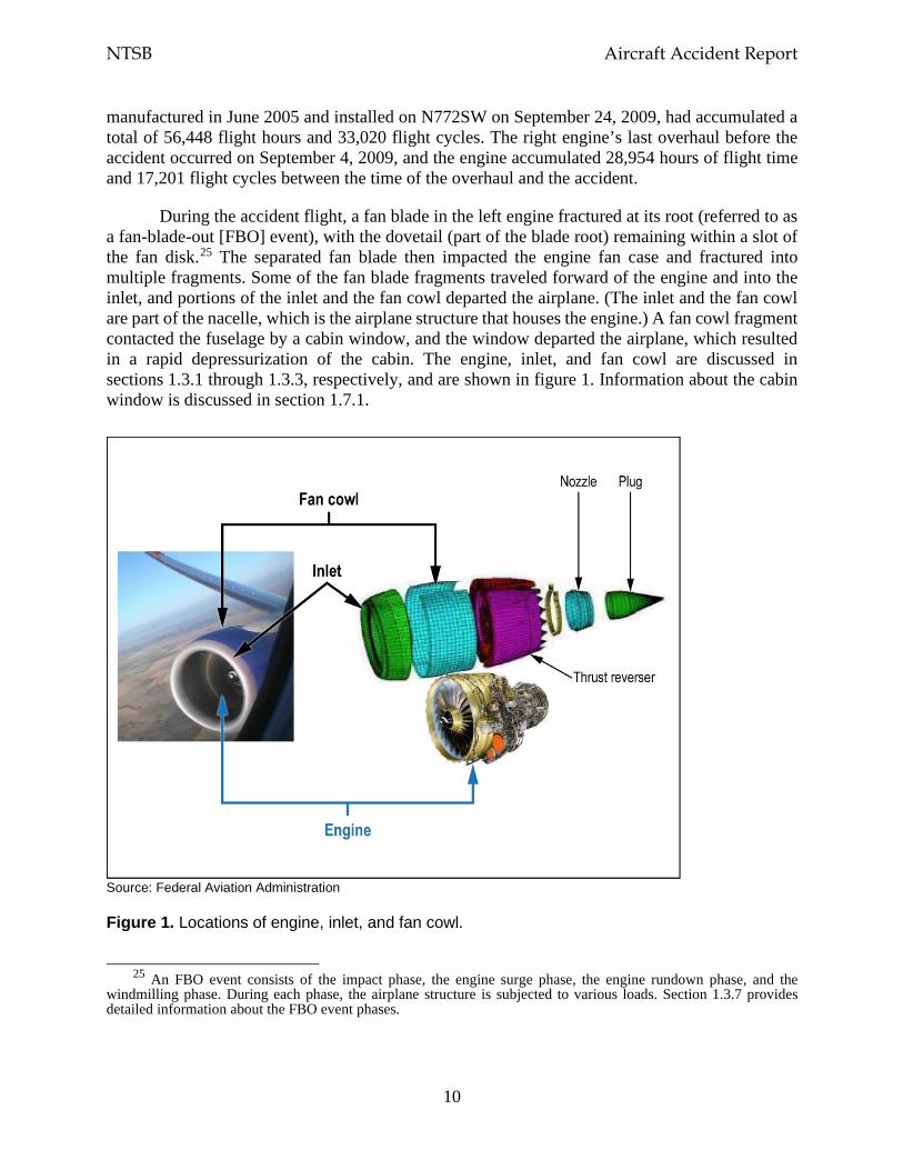
During the accident flight, a fan blade in the left engine fractured at its root (referred to as a fan-blade-out [FBO] event), with the dovetail (part of the blade root) remaining within a slot of the fan disk.25 The separated fan blade then impacted the engine fan case and fractured into multiple fragments. Some of the fan blade fragments traveled forward of the engine and into the inlet, and portions of the inlet and the fan cowl departed the airplane. (The inlet and the fan cowl are part of the nacelle, which is the airplane structure that houses the engine.) A fan cowl fragment contacted the fuselage by a cabin window, and the window departed the airplane, which resulted in a rapid depressurization of the cabin. The engine, inlet, and fan cowl are discussed in sections 1.3.1 through 1.3.3, respectively, and are shown in figure 1. Information about the cabin window is discussed in section 1.7.1.
Source: Federal Aviation Administration
Figure 1. Locations of engine, inlet, and fan cowl.
25 An FBO event consists of the impact phase, the engine surge phase, the engine rundown phase, and the
windmilling phase. During each phase, the airplane structure is subjected to various loads. Section 1.3.7 provides detailed information about the FBO event phases.
NTSB Aircraft Accident Report
11
1.3.1 Engine
The CFM56-7B is a high-bypass, dual-rotor, axial-flow turbofan engine.26 A single-stage high-pressure turbine (HPT) drives the nine-stage high-pressure compressor (HPC). A four-stage low-pressure turbine (LPT) drives the engine fan and low-pressure compressor (also referred to as the booster). The engine rotates clockwise (aft looking forward).
The engine consists of three major assemblies: the fan, engine core, and LPT, which are shown as part of figure 3 later in this section. GE is responsible for manufacturing the HPC, combustion chamber, and HPT (collectively referred to as the engine core). Safran is responsible for manufacturing the engine fan and LPT. Both companies assemble the engines; those assembled by GE are identified by an even engine serial number (ESN) prefix (for example, 874), and those assembled by Safran are identified by an odd ESN prefix (for example, 875). The ESN of the accident engine, 875134, showed that Safran assembled the engine.
The fan and booster assembly comprises the front and aft spinner cones, fan disk, fan blades, booster rotor, booster vanes, and associated hardware. The fan disk, which is secured to the booster, has 24 fan blade slots. In accordance with the instructions in Boeing’s 737-600/700/800/900 Aircraft Maintenance Manual, the fan blades are numbered sequentially (1 through 24) in the counterclockwise direction (forward looking aft).
The fan blades are made of a titanium alloy (known as Ti-6-4), and the dovetail part of the fan blade, which slides into the fan disk, has a copper-nickel-indium coating for wear protection.27 Before the application of the fan blade coating, the entire blade, including the dovetail, is shot-peened to increase the fatigue strength of the material and reduce surface tensile stresses that can lead to cracking. (Shot-peening is a process that adds a compressive residual stress surface layer to material, and residual stress is the stress that is present in solid material in the absence of external forces.)
Each CFM56-7B fan blade has a chord (width) of about 11 inches at its widest point.28 The nominal weight of each fan blade is about 10.83 pounds. The fan blades in the accident engine were manufactured in 2000 as part number 340-001-026-0; the part number was changed to 340-001-038-0 after the incorporation of a September 2012 CFM service bulletin (SB) to reidentify
26 CFM56-7B engine models comprise the -7B18, -7B20, -7B22, -7B24, -7B26, and -7B27. These engines are
installed in Boeing 737NG-series airplanes. Even though the CFM56-7B24 engine was installed in the accident airplane, the CFM56-7B references throughout this report apply to all of the engine models.
27 The copper-nickel-indium coating is applied by plasma spraying (a type of thermal spraying). A dry-film lubricant (molybdenum disulfide) is then applied to the exterior of the copper-nickel-indium coating to provide low frictional resistance.
28 The CFM56-7B fan blade has a wide chord compared with previous CFM fan blades, which had a chord of about 7 inches at their widest part. According to CFM, the advantages of a wide-chord fan blade are improved fuel burn and thrust, increased impact capability, and ease of maintenance (24 fan blades instead of 38 blades). CFM indicated, during the investigative hearing for this accident, that the regulatory requirements for the wide-chord fan blade are the same as those for fan blades with a narrower chord because the weight of the wide-chord blade is accounted for in the engine and fan case designs.

NTSB Aircraft Accident Report
12
some in-service fan blades. (No other modifications to the fan blades were made as a result of this SB.)
A spacer is installed under each fan blade root primarily to limit fan blade radial (outward) movement. The spacer also ensures that axial (longitudinal) loads can be transmitted to the fan blade axial retention feature during an FBO event. A shim is installed over each fan blade dovetail to prevent fretting (wear) of the fan disk pressure faces and reduce the amount of stress on the fan blade dovetail and the fan disk pressure faces.29 The fan disk and spacers are manufactured from a titanium alloy (Ti-6-4). The shims are manufactured from a nickel-chromium-iron alloy (alloy 718). A platform is installed on both sides of each fan blade to provide a smooth aerodynamic flow path between the blades. The platforms are manufactured from an aluminum alloy. Figure 2 shows the fan assembly.
Source: CFM
Figure 2. Fan assembly.
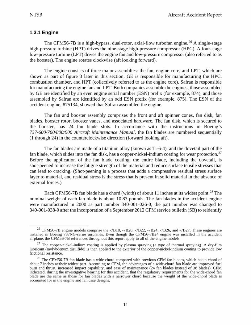
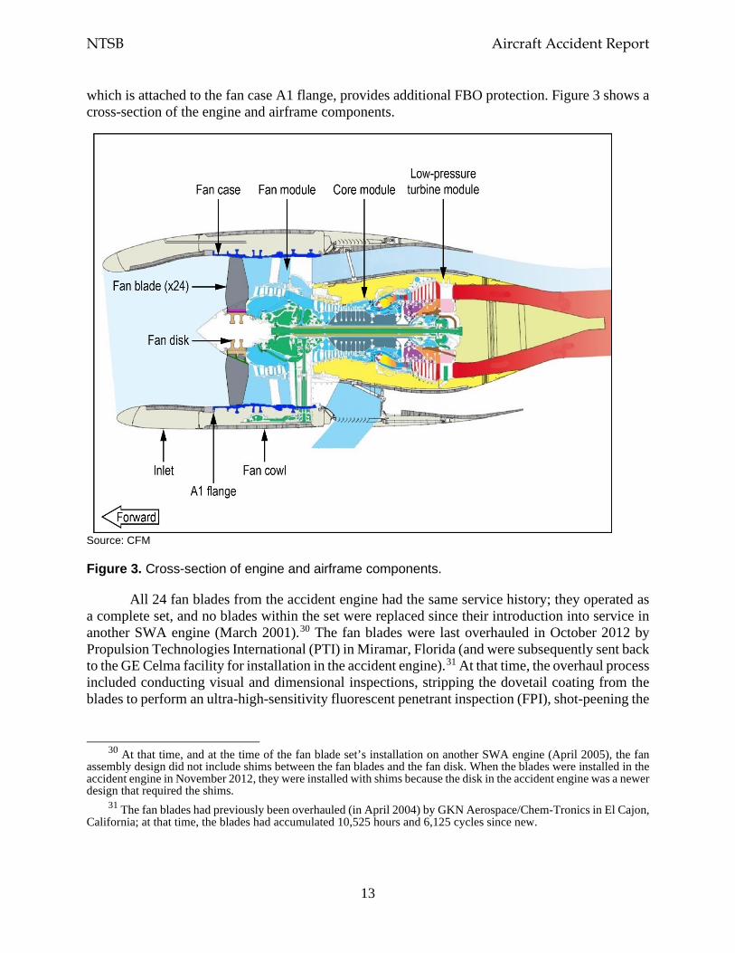
The fan frame assembly is the main forward support for the installation of the engine to the airframe and includes the fan frame, the fan case, and the fan outlet guide vanes. The fan case, which is made of an aluminum alloy, was designed to provide fan blade radial containment if an FBO event were to occur and transmit FBO loads to the fan frame and the inlet (part of the airframe). Although the fan case provides the primary FBO radial containment protection, the inlet,
29 The CFM SB introducing the shims (as well as a new fan disk and new spacers) as part of the CFM56-7B fan
disk configuration was issued in August 2004. This configuration change was implemented because of reports of premature flaking on the coating on the fan blade dovetail and wear on the pressure faces of the fan disk, which were determined to be the result of high local contact stress concentration.
NTSB Aircraft Accident Report
13
which is attached to the fan case A1 flange, provides additional FBO protection. Figure 3 shows a cross-section of the engine and airframe components.
Source: CFM
Figure 3. Cross-section of engine and airframe components.
All 24 fan blades from the accident engine had the same service history; they operated as a complete set, and no blades within the set were replaced since their introduction into service in another SWA engine (March 2001).30 The fan blades were last overhauled in October 2012 by Propulsion Technologies International (PTI) in Miramar, Florida (and were subsequently sent back to the GE Celma facility for installation in the accident engine).31 At that time, the overhaul process included conducting visual and dimensional inspections, stripping the dovetail coating from the blades to perform an ultra-high-sensitivity fluorescent penetrant inspection (FPI), shot-peening the
30 At that time, and at the time of the fan blade set’s installation on another SWA engine (April 2005), the fan
assembly design did not include shims between the fan blades and the fan disk. When the blades were installed in the accident engine in November 2012, they were installed with shims because the disk in the accident engine was a newer design that required the shims.
31 The fan blades had previously been overhauled (in April 2004) by GKN Aerospace/Chem-Tronics in El Cajon, California; at that time, the blades had accumulated 10,525 hours and 6,125 cycles since new.
NTSB Aircraft Accident Report
14
entire blade, and reapplying the dovetail coating.32 When the overhaul was performed, the fan blade set had accumulated 37,382 hours and 21,924 cycles since new.
Postaccident review of the PTI work orders related to the October 2012 overhaul of the accident fan blade set showed that all fan blades were processed according to the repair instructions and that all fan blades passed the final quality check and thus did not require any rework. In addition, review of the PTI metallurgical testing records showed that no anomalies had been noted for any of the coating requirements, including surface condition, microstructure, bond strength, thickness, and hardness. At the time of the accident, the fan blade set had accumulated 55,471 hours and 32,636 cycles since new and 18,088 hours and 10,712 cycles since the time of the overhaul.
The CFM56-7B fan blade was not certified as a life-limited part. To maintain the fan blade loads within the predicted range and prevent wear on the fan disk and the fan blade dovetail coating, CFM recommended repetitive on-wing relubrications of the dovetails. As part of the relubrication, the fan blades are visually inspected to assess the blade coating condition and identify any airfoil damage and crack indications.
At the time of the fan blades’ last overhaul in October 2012, the CFM-recommended fan blade dovetail relubrication interval was every 3,000 cycles or 5,000 hours, whichever came first. At the time of the SWA flight 1380 accident, the recommended relubrication interval was every 1,500 to 3,000 cycles. Between November 29, 2012 (the date that the accident engine was installed on the SWA flight 1380 airplane) and April 17, 2018 (the date of the SWA flight 1380 accident), the dovetails on the fan blade set were relubricated seven times.33 The number of cycles between each relubrication did not exceed the CFM-recommended relubrication interval at the time, and the fan blades had accumulated 1,704 cycles since the last relubrication. In October 2018, CFM further reduced the relubrication interval to every 1,600 cycles; this change appeared immediately in the electronic version of Boeing’s 737-600/-700/-800/-900/-900ER maintenance planning document.
1.3.2 Inlet
The inlet is an aerodynamic fairing assembly that is attached to the engine at the fan case A1 flange with 24 bolted assemblies (fasteners). The inlet directs smooth uninterrupted airflow into the engine fan and core sections and is an external aerodynamic pressure surface that directs the airflow over the fan cowl and other nacelle components. The inlet was developed between 1994 and 1997 with a design configuration and materials similar to those of the 737-300, a
32 An FPI is a nondestructive inspection method that detects cracks and other anomalies at the surface. Starting
in November 2016, the overhaul process requirements included an eddy current inspection; see section 1.10.1 for information about that inspection.
33 The relubrications occurred in July 2013, March and November 2014, July and August 2015, April 2016, and June 2017.
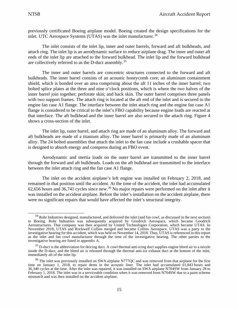
NTSB Aircraft Accident Report
15
previously certificated Boeing airplane model. Boeing created the design specifications for the inlet. UTC Aerospace Systems (UTAS) was the inlet manufacturer.34
The inlet consists of the inlet lip, inner and outer barrels, forward and aft bulkheads, and attach ring. The inlet lip is an aerodynamic surface to reduce airplane drag. The inner and outer aft ends of the inlet lip are attached to the forward bulkhead. The inlet lip and the forward bulkhead are collectively referred to as the D-duct assembly.35
The inner and outer barrels are concentric structures connected to the forward and aft bulkheads. The inner barrel consists of an acoustic honeycomb core; an aluminum containment shield, which is bonded over an area comprising about the aft 11 inches of the inner barrel; two bolted splice plates at the three and nine o’clock positions, which is where the two halves of the inner barrel join together; perforate skin; and back skin. The outer barrel comprises three panels with two support frames. The attach ring is located at the aft end of the inlet and is secured to the engine fan case A1 flange. The interface between the inlet attach ring and the engine fan case A1 flange is considered to be critical to the inlet’s FBO capability because engine loads are reacted at that interface. The aft bulkhead and the inner barrel are also secured to the attach ring. Figure 4 shows a cross-section of the inlet.
The inlet lip, outer barrel, and attach ring are made of an aluminum alloy. The forward and aft bulkheads are made of a titanium alloy. The inner barrel is primarily made of an aluminum alloy. The 24 bolted assemblies that attach the inlet to the fan case include a crushable spacer that is designed to absorb energy and compress during an FBO event.
Aerodynamic and inertia loads on the outer barrel are transmitted to the inner barrel through the forward and aft bulkheads. Loads on the aft bulkhead are transmitted to the interface between the inlet attach ring and the fan case A1 flange.
The inlet on the accident airplane’s left engine was installed on February 2, 2018, and remained in that position until the accident. At the time of the accident, the inlet had accumulated 62,656 hours and 36,741 cycles since new.36 No major repairs were performed on the inlet after it was installed on the accident airplane. Before the inlet’s installation on the accident airplane, there were no significant repairs that would have affected the inlet’s structural integrity.
34 Rohr Industries designed, manufactured, and delivered the inlet (and fan cowl, as discussed in the next section)
to Boeing. Rohr Industries was subsequently acquired by Goodrich Aerospace, which became Goodrich Aerostructures. That company was then acquired by United Technologies Corporation, which became UTAS. In November 2018, UTAS and Rockwell Collins merged and became Collins Aerospace. UTAS was a party to the investigative hearing for this accident, which was held on November 14, 2018. Thus, UTAS is referenced in this report as the inlet and fan cowl manufacturer through the time of the investigative hearing. The other parties to the investigative hearing are listed in appendix A.
35 D-duct is the abbreviation for deicing duct. A cowl thermal anti-icing duct supplies engine bleed air to a nozzle inside the D-duct, and the bleed air is released through the thermal anti-ice exhaust duct at the bottom of the inlet, immediately aft of the inlet lip.
36 The inlet was previously installed on SWA airplane N777QC and was removed from that airplane for the first time on January 1, 2018, to repair dents in the acoustic liner. The inlet had accumulated 61,843 hours and 36,340 cycles at the time. After the inlet was repaired, it was installed on SWA airplane N704SW from January 28 to February 1, 2018. The inlet was in a serviceable condition when it was removed from N704SW due to a paint scheme mismatch and was then installed on the accident airplane.
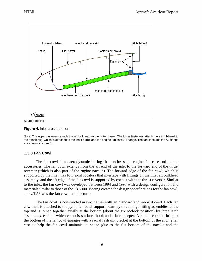
NTSB Aircraft Accident Report
16
Source: Boeing
Figure 4. Inlet cross-section.
Note: The upper fasteners attach the aft bulkhead to the outer barrel. The lower fasteners attach the aft bulkhead to the attach ring, which is attached to the inner barrel and the engine fan case A1 flange. The fan case and the A1 flange are shown in figure 3.
1.3.3 Fan Cowl
The fan cowl is an aerodynamic fairing that encloses the engine fan case and engine accessories. The fan cowl extends from the aft end of the inlet to the forward end of the thrust reverser (which is also part of the engine nacelle). The forward edge of the fan cowl, which is supported by the inlet, has four axial locators that interface with fittings on the inlet aft bulkhead assembly, and the aft edge of the fan cowl is supported by contact with the thrust reverser. Similar to the inlet, the fan cowl was developed between 1994 and 1997 with a design configuration and materials similar to those of the 737-300. Boeing created the design specifications for the fan cowl, and UTAS was the fan cowl manufacturer.
The fan cowl is constructed in two halves with an outboard and inboard cowl. Each fan cowl half is attached to the pylon fan cowl support beam by three hinge fitting assemblies at the top and is joined together axially at the bottom (about the six o’clock position) by three latch assemblies, each of which comprises a latch hook and a latch keeper. A radial restraint fitting at the bottom of the fan cowl engages with a radial restraint bracket at the bottom of the engine fan case to help the fan cowl maintain its shape (due to the flat bottom of the nacelle and the
NTSB Aircraft Accident Report
17
asymmetric design of the fan cowl).37 Figure 5 shows the components for the fan cowl on the left engine. As shown in the figure, the latch hooks are located on the outboard cowl, and the latch keepers and radial restraint fitting are located on the inboard cowl.38 Figure 10 (in section 1.3.4.3) shows the radial restraint bracket from the accident engine fan case.
Source: Boeing
Figure 5. Left engine fan cowl.
Note: Latch No. 1 is the forward latch, latch No. 2 is the center latch, and latch No. 3 is the aft latch. The general locations of the axial locators (and not the axial locators themselves) are shown in the figure.
The fan cowl skin and frame are made of an aluminum alloy, the fan cowl hinges are made of a titanium alloy, and the latch housings (for the latch hooks and latch keepers) are made of an aluminum alloy. Flight and ground loads carried by the fan cowl skins are transferred to the fan cowl support beam at the hinge interfaces. Radial loads are reacted at the radial restraint fitting (as
37 The early 737 airplane models (the 737-100 and -200) had JT8D low-bypass-ratio engines installed under the
airplane’s wings. During the development of the 737-300 in the early 1980s, Boeing introduced the CFM56-3 engine, which was a high-bypass-ratio engine that had a larger diameter than the previous 737 engine model. The larger diameter of the CFM56-3 engine resulted in a ground clearance issue, which was resolved by redesigning the nacelle with a flat bottom. The CFM56-7B engine on 737NG-series airplanes also has a large diameter, which necessitated a nacelle with a flat bottom.
38 For the fan cowl on the right engine, the latch hooks were located on the inboard cowl, and the latch keepers and radial restraint pin were located on the outboard cowl.
NTSB Aircraft Accident Report
18
well as at the inlet aft bulkhead and the fan cowl aft interface with the thrust reverser). Axial forward and aft loads are reacted at the four axial locators and the fan cowl hinges.
The fan cowl on the accident airplane’s left engine was the original fan cowl delivered with the airplane. The fan cowl was inspected on March 30, 2018, as part of a general visual inspection of the engines and nacelles. This inspection is required every 560 flight cycles or 90 days, whichever comes first. In addition, the fan cowls are inspected as part of the airplane exterior general visual inspection conducted every 8 days; this inspection was performed 2 days before the accident. The National Transportation Safety Board’s (NTSB) review of SWA maintenance records for the fan cowl during the 10 years preceding the accident found no nonroutine items for the latch hooks or latch keepers; the records showed that only minor in-service repairs were performed.
1.3.4 Postaccident Examinations
Postaccident examination of the airplane at PHL found that the left fuselage, the left-wing leading edges and upper and lower surfaces, and the left horizontal stabilizer showed evidence of impact damage (surface scratching and skin gouging, tears, and penetrations) along with blue and red paint transfer. The following airplane parts were recovered near Bernville, Pennsylvania, which corresponded to the coordinates of the location where the FBO event occurred:39
• parts from the D-duct assembly (comprising the inlet lip and forward bulkhead), • parts of the inlet inner and outer barrels, • part of the inlet aft bulkhead, • parts of the outboard and inboard fan cowl sections, and • multiple small parts and paint chips.
Sections 1.3.4.2 and 1.3.4.3 provide details about the recovered inlet and fan cowl parts.
The fuselage skin below the passenger window near seat 14A exhibited evidence of impact damage (witness marks and a small puncture just below the window).40 The lower aft corner of the section of the inboard fan cowl that departed the airplane also exhibited evidence of impact damage. The lower aft corner edges of the inboard fan cowl section aligned with the fuselage witness marks, as shown in figure 6, indicating that the impact-damaged surfaces were similar. No windowpane fragments or window frame material were found inside the airplane or during the ground recovery of airplane debris.
39 The coordinates were about 40.444° north latitude and 76.235° west longitude. 40 The puncture was about 1 inch long, 1 inch wide, and 0.2 inch deep.
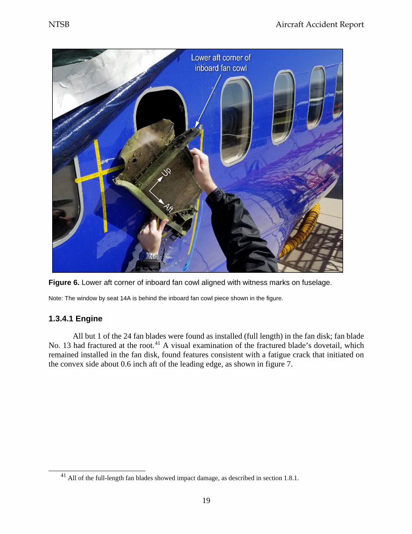
NTSB Aircraft Accident Report
19
Figure 6. Lower aft corner of inboard fan cowl aligned with witness marks on fuselage.
Note: The window by seat 14A is behind the inboard fan cowl piece shown in the figure.
1.3.4.1 Engine
All but 1 of the 24 fan blades were found as installed (full length) in the fan disk; fan blade No. 13 had fractured at the root.41 A visual examination of the fractured blade’s dovetail, which remained installed in the fan disk, found features consistent with a fatigue crack that initiated on the convex side about 0.6 inch aft of the leading edge, as shown in figure 7.
41 All of the full-length fan blades showed impact damage, as described in section 1.8.1.
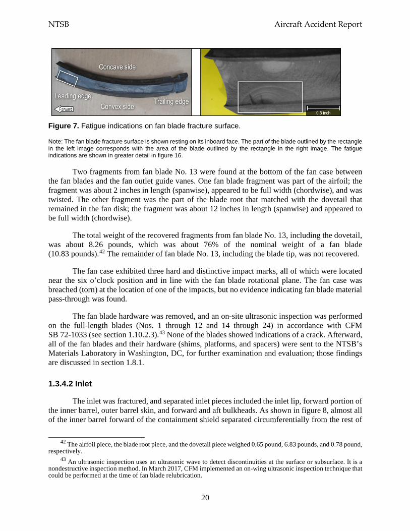
NTSB Aircraft Accident Report
20
Figure 7. Fatigue indications on fan blade fracture surface.
Note: The fan blade fracture surface is shown resting on its inboard face. The part of the blade outlined by the rectangle in the left image corresponds with the area of the blade outlined by the rectangle in the right image. The fatigue indications are shown in greater detail in figure 16.
Two fragments from fan blade No. 13 were found at the bottom of the fan case between the fan blades and the fan outlet guide vanes. One fan blade fragment was part of the airfoil; the fragment was about 2 inches in length (spanwise), appeared to be full width (chordwise), and was twisted. The other fragment was the part of the blade root that matched with the dovetail that remained in the fan disk; the fragment was about 12 inches in length (spanwise) and appeared to be full width (chordwise).
The total weight of the recovered fragments from fan blade No. 13, including the dovetail, was about 8.26 pounds, which was about 76% of the nominal weight of a fan blade (10.83 pounds).42 The remainder of fan blade No. 13, including the blade tip, was not recovered.
The fan case exhibited three hard and distinctive impact marks, all of which were located near the six o’clock position and in line with the fan blade rotational plane. The fan case was breached (torn) at the location of one of the impacts, but no evidence indicating fan blade material pass-through was found.
The fan blade hardware was removed, and an on-site ultrasonic inspection was performed on the full-length blades (Nos. 1 through 12 and 14 through 24) in accordance with CFM SB 72-1033 (see section 1.10.2.3).43 None of the blades showed indications of a crack. Afterward, all of the fan blades and their hardware (shims, platforms, and spacers) were sent to the NTSB’s Materials Laboratory in Washington, DC, for further examination and evaluation; those findings are discussed in section 1.8.1.
1.3.4.2 Inlet
The inlet was fractured, and separated inlet pieces included the inlet lip, forward portion of the inner barrel, outer barrel skin, and forward and aft bulkheads. As shown in figure 8, almost all of the inner barrel forward of the containment shield separated circumferentially from the rest of
42 The airfoil piece, the blade root piece, and the dovetail piece weighed 0.65 pound, 6.83 pounds, and 0.78 pound,
respectively. 43 An ultrasonic inspection uses an ultrasonic wave to detect discontinuities at the surface or subsurface. It is a
nondestructive inspection method. In March 2017, CFM implemented an on-wing ultrasonic inspection technique that could be performed at the time of fan blade relubrication.
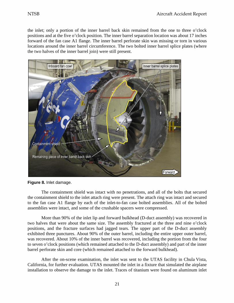
NTSB Aircraft Accident Report
21
the inlet; only a portion of the inner barrel back skin remained from the one to three o’clock positions and at the five o’clock position. The inner barrel separation location was about 17 inches forward of the fan case A1 flange. The inner barrel perforate skin was missing or torn in various locations around the inner barrel circumference. The two bolted inner barrel splice plates (where the two halves of the inner barrel join) were still present.
Figure 8. Inlet damage.
The containment shield was intact with no penetrations, and all of the bolts that secured the containment shield to the inlet attach ring were present. The attach ring was intact and secured to the fan case A1 flange by each of the inlet-to-fan case bolted assemblies. All of the bolted assemblies were intact, and some of the crushable spacers were compressed.
More than 90% of the inlet lip and forward bulkhead (D-duct assembly) was recovered in two halves that were about the same size. The assembly fractured at the three and nine o’clock positions, and the fracture surfaces had jagged tears. The upper part of the D-duct assembly exhibited three punctures. About 90% of the outer barrel, including the entire upper outer barrel, was recovered. About 10% of the inner barrel was recovered, including the portion from the four to seven o’clock positions (which remained attached to the D-duct assembly) and part of the inner barrel perforate skin and core (which remained attached to the forward bulkhead).
After the on-scene examination, the inlet was sent to the UTAS facility in Chula Vista, California, for further evaluation. UTAS mounted the inlet in a fixture that simulated the airplane installation to observe the damage to the inlet. Traces of titanium were found on aluminum inlet
NTSB Aircraft Accident Report
22
components, including the containment shield (at the forward edge) and the outer barrel. The inner barrel assembly back skin was completely separated forward of the containment shield, which had fractures and deformations. No evidence of fatigue was found on the back skin and acoustic core. The inner barrel back skin fracture surfaces exhibited tension, shear, and/or tension overload with areas of outward shear-lip deformations and alternating-direction (inward and outward) shear-lip deformations.44
The available evidence did not specifically indicate whether the source of some inlet damage, including damage to the inner barrel back skin, was caused by forward-traveling fan blade fragments or engine rundown (that is, the engine fan rotor deceleration before windmilling begins, as further discussed in section 1.3.7.1). Thus, to better assess the amount of inner barrel back skin damage, estimates of both the minimum and maximum inner barrel back skin damage were developed (instead of a single damage estimate), and both estimates were expressed as the number of degrees around the circumference of the inlet (arc length).
The amount of inner barrel back skin damage (before the inner barrel separated from the inlet) was determined by an evaluation of the fragment trajectories, a metallurgical analysis of the inner barrel back skin, and the presence of fan blade material transfer from the blade fragments to the inner and outer barrel.45 The inner barrel back skin damage (forward of the containment shield) that could be positively identified (either through visual observations or metallurgical analysis) as having been caused by forward-traveling fan blade fragments had an estimated arc length that ranged from 70° to 180°.
1.3.4.3 Fan Cowl
Almost all of the outboard (left) fan cowl was missing; only some small pieces remained attached to the pylon. The forward, middle, and aft hinges were present. The forward outboard hinge was attached to a small piece of the fan cowl panel, but the middle and aft outboard hinges were not attached to any fan cowl structure. The forward and middle outboard hinges appeared distorted.
The inboard (right) fan cowl was substantially damaged, as shown in figure 9, and was rotated aft. The inboard fan cowl had fractured and was missing about one-half of its bottom portion from about the four to six o’clock positions. The upper cowl panel in the inboard fan cowl remained attached to the airplane via the forward, middle, and aft hinges. Most of the starter air vent (located at the bottom of the fan cowl in line with the radial restraint fitting) was missing, and the attach flanges for the vent showed overstress fracture features.
44 Other damage to the inlet that UTAS documented included gouges and indentations in the inner barrel flow-
side attach ring, perforate skin, and acoustic core and punctures in the outer barrel. 45 In addition to UTAS’ metallurgical analysis of the inner barrel back skin, UTAS performed metallurgical
analyses for (1) the inner barrel assembly acoustic core, perforate skin, containment shield, and splice plates at the three and nine o’clock positions; (2) the outer barrel assembly upper and lower skins, aft bulkhead webs, and aft bulkhead T-frame; and (3) the D-duct assembly (inlet lip and forward bulkhead).
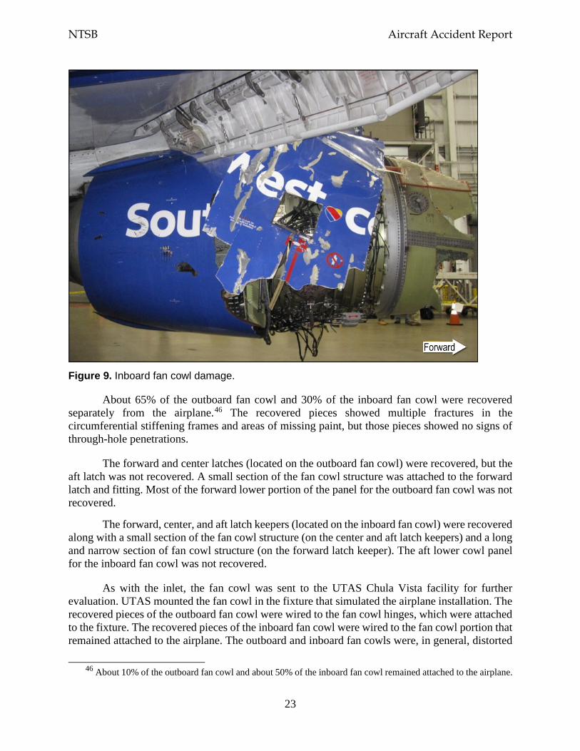
NTSB Aircraft Accident Report
23
Figure 9. Inboard fan cowl damage.
About 65% of the outboard fan cowl and 30% of the inboard fan cowl were recovered separately from the airplane.46 The recovered pieces showed multiple fractures in the circumferential stiffening frames and areas of missing paint, but those pieces showed no signs of through-hole penetrations.
The forward and center latches (located on the outboard fan cowl) were recovered, but the aft latch was not recovered. A small section of the fan cowl structure was attached to the forward latch and fitting. Most of the forward lower portion of the panel for the outboard fan cowl was not recovered.
The forward, center, and aft latch keepers (located on the inboard fan cowl) were recovered along with a small section of the fan cowl structure (on the center and aft latch keepers) and a long and narrow section of fan cowl structure (on the forward latch keeper). The aft lower cowl panel for the inboard fan cowl was not recovered.
As with the inlet, the fan cowl was sent to the UTAS Chula Vista facility for further evaluation. UTAS mounted the fan cowl in the fixture that simulated the airplane installation. The recovered pieces of the outboard fan cowl were wired to the fan cowl hinges, which were attached to the fixture. The recovered pieces of the inboard fan cowl were wired to the fan cowl portion that remained attached to the airplane. The outboard and inboard fan cowls were, in general, distorted
46 About 10% of the outboard fan cowl and about 50% of the inboard fan cowl remained attached to the airplane.
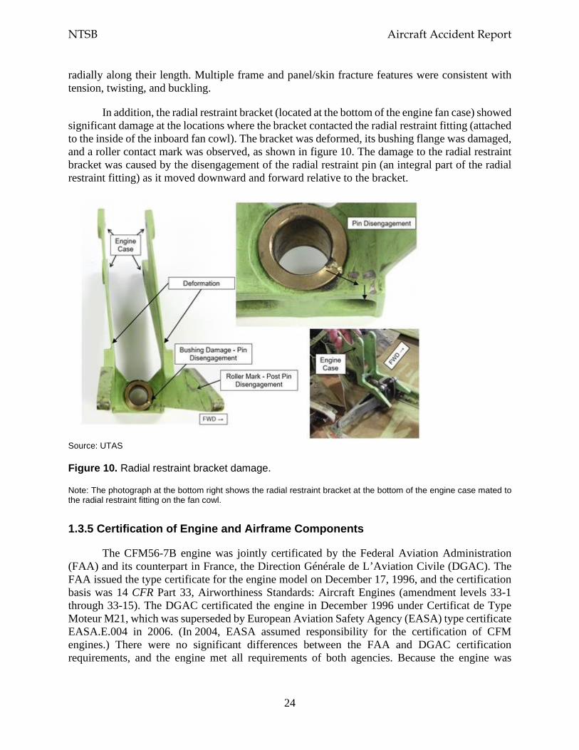
NTSB Aircraft Accident Report
24
radially along their length. Multiple frame and panel/skin fracture features were consistent with tension, twisting, and buckling.
In addition, the radial restraint bracket (located at the bottom of the engine fan case) showed significant damage at the locations where the bracket contacted the radial restraint fitting (attached to the inside of the inboard fan cowl). The bracket was deformed, its bushing flange was damaged, and a roller contact mark was observed, as shown in figure 10. The damage to the radial restraint bracket was caused by the disengagement of the radial restraint pin (an integral part of the radial restraint fitting) as it moved downward and forward relative to the bracket.
Source: UTAS
Figure 10. Radial restraint bracket damage.
Note: The photograph at the bottom right shows the radial restraint bracket at the bottom of the engine case mated to the radial restraint fitting on the fan cowl.
1.3.5 Certification of Engine and Airframe Components
The CFM56-7B engine was jointly certificated by the Federal Aviation Administration (FAA) and its counterpart in France, the Direction Générale de L’Aviation Civile (DGAC). The FAA issued the type certificate for the engine model on December 17, 1996, and the certification basis was 14 CFR Part 33, Airworthiness Standards: Aircraft Engines (amendment levels 33-1 through 33-15). The DGAC certificated the engine in December 1996 under Certificat de Type Moteur M21, which was superseded by European Aviation Safety Agency (EASA) type certificate EASA.E.004 in 2006. (In 2004, EASA assumed responsibility for the certification of CFM engines.) There were no significant differences between the FAA and DGAC certification requirements, and the engine met all requirements of both agencies. Because the engine was
NTSB Aircraft Accident Report
25
dual-certificated, the certification basis also included Joint Aviation Requirements JAR-E Change 8 (dated May 4, 1990).47
The Boeing 737-700 airplane was certificated on November 7, 1997. The certification basis was 14 CFR Part 25, Airworthiness Standards: Transport Category Airplanes.
When the CFM56-7B engine and the Boeing 737-700 airplane were certificated, an FBO event was generally considered to have two major stages. The first stage was the failure event itself, during which fan blades and/or other internal engine debris could be released from the engine (addressed by Part 33). This stage included the failed engine’s impact loads, surge pressure loads, and rundown loads during the engine’s rapid deceleration and accounted for fan blade trajectories and energies, engine torque, engine thrust decay, and imbalance loads.48
The second stage was the effect that the failed engine could have on the airplane’s airframe, systems, and occupants, including the airplane’s ability to safely fly and land (addressed by Part 25). This stage, which is typically referred to as the “fly home” phase, accounted for the imbalance loads from a continuously windmilling engine and structural damage to the inlet.
1.3.5.1 Engine Certification Regulations
Turbine engine fan blade containment requirements are found in Part 33 Subpart B, Design and Construction (section 33.19), and Subpart F, Block Tests; Turbine Aircraft Engines (section 33.94). The fan blade containment requirements in these sections were implemented in 1984 and are still in effect.
Section 33.19, Durability, paragraph (a), states the following: “The design of the compressor and turbine rotor cases must provide for the containment of the damage from rotor blade failure.” Historically, this regulation has meant that engine debris cannot penetrate and pass radially through the engine case but that debris can exit axially from the front or back of an engine. Section 33.19(a) also states that “energy levels [mass, trajectory, and velocity angles] and trajectories of fragments resulting from rotor blade failure that lie outside the compressor and turbine rotor cases must be defined.”
Section 33.94, Blade Containment and Rotor Unbalance Tests, paragraphs (a) and (a)(1), address requirements to preclude damage resulting from an FBO event. These paragraphs state that engine tests must demonstrate the following:
The engine is capable of containing damage without catching fire and without failure of its mounting attachments when operated for at least 15 seconds, unless the resulting engine damage induces a self shutdown after…failure of the most
47 According to the FAA, before EASA was created, the Joint Aviation Authorities (which represented several
European civil aviation regulatory authorities) were responsible for publishing regulations, known as the Joint Aviation Requirements, which addressed, among other things, aircraft certification and design standards (https://www.skybrary.aero/index.php/JARs).
48 Section 1.3.7.1 provides detailed information about the various loads that are imparted to the airplane structure during these FBO event phases (impact, engine surge, and engine rundown).
NTSB Aircraft Accident Report
26
critical compressor or fan blade while operating at [the] maximum permissible r.p.m.
FAA Advisory Circular (AC) 33-5, “Turbine Engine Rotor Blade Containment/Durability,” was issued on June 18, 1990, to provide guidance on acceptable design and test methods for compliance with Part 33 requirements regarding turbine engine fan blade containment. According to the AC, “contained” was defined as “no fragments are released through the engine structure, but fragments may be ejected out of the engine air inlet or exhaust.” Also, the AC defined “engine structure” as the “structure surrounding the main rotors and extending from the forward-most case flange through the rear-most flange, as defined by the type design.” In addition, the AC provided the engine configuration, conditions, and acceptable results for fan blade containment tests.
1.3.5.2 Tests for Engine Certification
To meet Part 33 requirements and obtain data for Boeing (as the airframe manufacturer) to use to meet Part 25 certification requirements (discussed in the next section), CFM performed eight development FBO rig tests and two engine FBO containment certification tests.49 The purposes of the FBO tests were to (1) understand the fan blade fragmentation and kinematics (fragment energy levels and trajectories) after blade separation, (2) determine the fan case containment capability (radial containment), (3) define the loads and displacements from the initial impact and the resulting engine imbalance, (4) calculate the speed and weight of any ejected fragments (forward containment), and (5) demonstrate the proposed production hardware configuration.50
Each rig test had a specific set of objectives and used various fan blade and fan case configurations. The first four FBO rig tests were designed to define the fan blade fragmentation and kinematics for fan case radial containment capability, fan blade axial retention, and fan blade interaction. The fourth FBO rig test included a full set of production-representative fan blades, a production-representative fan case, and a combination of actual and production-representative engine accessories. Also included in this test was a Boeing production-representative inlet, which had the same size, shape, and stiffness of the intended production inlet at that time. The production-representative inlet included crushable spacers but did not include a containment shield.
FBO rig test 4, which was conducted in August 1995, revealed that the separated fan blade fractured into five pieces with the blade tip panel traveling forward of the fan case and into the inlet at an estimated 10° to 15° helix angle (where the fragment crossed the A1 flange).51 Figure 11 shows a general example of a helix angle. The blade tip panel spiraled around the inlet and then penetrated the inlet inner and outer barrels. The inner barrel penetration was about 26° forward of
49 According to information that the FAA provided for the investigative hearing for this accident, the minimum
data required to be shared between the engine manufacturer and the airframe manufacturer are the maximum loads and the energy and trajectory of the debris that exits the engine. The engine manufacturer can share additional information to facilitate the design and installation of the airframe.
50 Kinematics is the study of motion of an object, including its trajectory and speed. 51 After a fan blade release, fan blade airfoil and tip fragments generally travel in a forward spiral/helical pattern
around the fan case and inlet.
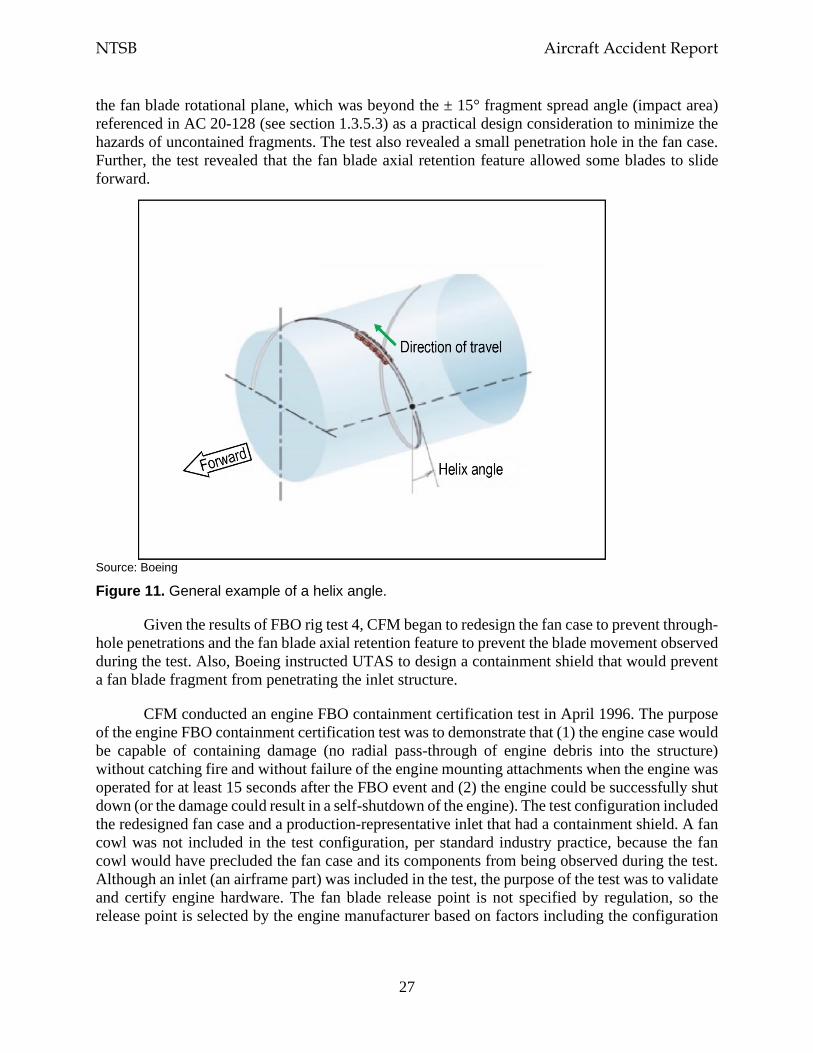
NTSB Aircraft Accident Report
27
the fan blade rotational plane, which was beyond the ± 15° fragment spread angle (impact area) referenced in AC 20-128 (see section 1.3.5.3) as a practical design consideration to minimize the hazards of uncontained fragments. The test also revealed a small penetration hole in the fan case. Further, the test revealed that the fan blade axial retention feature allowed some blades to slide forward.
Source: Boeing
Figure 11. General example of a helix angle.
Given the results of FBO rig test 4, CFM began to redesign the fan case to prevent through-hole penetrations and the fan blade axial retention feature to prevent the blade movement observed during the test. Also, Boeing instructed UTAS to design a containment shield that would prevent a fan blade fragment from penetrating the inlet structure.
CFM conducted an engine FBO containment certification test in April 1996. The purpose of the engine FBO containment certification test was to demonstrate that (1) the engine case would be capable of containing damage (no radial pass-through of engine debris into the structure) without catching fire and without failure of the engine mounting attachments when the engine was operated for at least 15 seconds after the FBO event and (2) the engine could be successfully shut down (or the damage could result in a self-shutdown of the engine). The test configuration included the redesigned fan case and a production-representative inlet that had a containment shield. A fan cowl was not included in the test configuration, per standard industry practice, because the fan cowl would have precluded the fan case and its components from being observed during the test. Although an inlet (an airframe part) was included in the test, the purpose of the test was to validate and certify engine hardware. The fan blade release point is not specified by regulation, so the release point is selected by the engine manufacturer based on factors including the configuration
NTSB Aircraft Accident Report
28
of the test stand and the location of the mounted lights and recording devices. For the CFM56-7B certification tests, CFM selected the twelve o’clock position as the fan blade release point.
According to CFM, the test results showed that, after the initial fan blade release, the fan case withstood the impact with no penetrations, the engine did not catch fire, the engine mounting hardware did not fail, and the engine was able to be shut down. The test results also showed that the inlet remained attached to the engine and that no fan blade fragments penetrated the containment shield. Afterward, five consecutive fan blades moved forward out of the fan disk, indicating that the blades’ axial retention capability had failed. The fan case and the inlet were subsequently damaged by pass-through penetrations, and the inlet was further damaged due to missing inner and outer barrel material and the severing (360° circumferentially) of the aft bulkhead-to-attach ring joint.
Boeing and UTAS determined that, even with the inlet damage, a redesign of the inlet was not necessary and additional inlet testing was not required because (1) the inlet remained attached to the engine; (2) the inlet withstood the initial FBO impact, the surge pressure loads, and the rundown loads; and (3) the containment shield performed appropriately during the initial fan blade release. CFM redesigned the fan blade axial retention feature based on the results of this certification test and conducted four additional rig tests to ensure that the redesigned feature would prevent fan blade axial movement.
CFM conducted a second engine FBO containment certification test in December 1996. Because the inlet was not part of the configuration for the second certification test, an aerodynamic bellmouth with a similar weight, stiffness, and flow-path shape as a production-representative inlet was used for the test.52 The second engine FBO certification test revealed fan blade fragmentation that was similar to that observed during the previous certification test and demonstrated that the fan blade axial retention feature had been successfully redesigned. Thus, the CFM56-7B engine met the fan blade containment certification requirements under Part 33.
1.3.5.3 Airplane Certification Regulations
Numerous regulations under Part 25 applied to the inlet, the fan cowl, and other structures. These regulations included sections 25.571(e) and 25.629(d) (under Subpart C, Structure, through amendment level 25-77) and sections 25.901 and 25.903 (under Subpart E, Powerplant, through amendment level 25-77 and 25-73, respectively), which were intended to evaluate potential engine failures and their consequences to the airplane and ensure the airplane’s safe flight and landing.
Section 25.571, Damage—Tolerance and Fatigue Evaluation of Structure, paragraph (e), stated the following: “the airplane must be capable of successfully completing a flight during which likely structural damage occurs” as a result of an uncontained fan blade impact, an uncontained engine failure, or an uncontained high-energy rotating machinery failure. This paragraph also stated that “the damaged structure must be able to withstand the static loads (considered as ultimate loads) which are reasonably expected to occur on the flight” and “if
52 The bellmouth was installed to the test stand using airplane mounting hardware. CFM conducted an analysis
to determine the impact of using the bellmouth and found that the differences between the production-representative inlet and the bellmouth would not affect the test objectives or the FBO loads.

NTSB Aircraft Accident Report
29
significant changes in structural stiffness or geometry, or both, follow from a structural failure or partial failure, the effect on damage tolerance must be further investigated.”
Section 25.629, Aeroelastic Stability Requirements, paragraph (d), addressed failures, malfunctions, and adverse conditions that were required to be considered to show compliance with this section. These considerations included the “failure of any single element of the structure supporting any engine,” any damage, failure, or malfunction addressed by other relevant Part 25 sections, and “any other combination of failures, malfunctions, or adverse conditions not shown to be extremely improbable.”
Section 25.901, Installation, paragraph (c), stated that, for each powerplant installation, “it must be established that no single failure or malfunction or probable combination of failures will jeopardize the safe operation of the airplane.” The paragraph also indicated that “the failure of structural elements need not be considered if the probability of such failures is extremely remote.”
Section 25.903, Engines, paragraph (c), discussed control of engine rotation and stated that, for turbine engine installations, “the means for stopping the rotation of any engine [during flight] need be provided only where continued rotation could jeopardize the safety of the airplane.” Paragraph (d)(1) stated that, for turbine engine installations, “design precautions must be taken to minimize the hazards to the airplane in the event of an engine rotor failure.”
On March 9, 1988, the FAA issued AC 20-128, “Design Considerations for Minimizing Hazards Caused by Uncontained Turbine Engine and Auxiliary Power Unit Rotor Failure,” to provide guidance on appropriate design precautions to minimize the hazards to the airplane in the event of an engine failure and acceptable methods for demonstrating compliance with section 25.903(d)(1).53 The AC stated the following:
For the purposes of airplane evaluations in accordance with this AC, uncontained failure of a turbine engine is any failure which results in the escape of rotor fragments from the engine or APU [auxiliary power unit] that could result in a hazard. Rotor failures which are of a concern are those where released fragments have sufficient energy to create a hazard to the airplane.
AC 20-128 defined various fragment spread angles (based on historic engine failure events) and the area of the airplane that would likely be impacted by uncontained engine fragments. The AC included a figure that further explained fragment spread angles. The figure showed that, for an FBO event, an airframe manufacturer was expected to assume that fan blade fragments would exit the engine at an angle that was ± 15° forward and aft from the center of the plane of rotation of an individual rotor stage initiating at the engine shaft centerline. The AC noted that airplane designs should “consider the likely damage extent caused by multiple smaller fragments or shrapnel in the ±15° spread angle areas” and that the “engine installer should consider the engine manufacturer’s data on fragment energies and trajectories in relation to the engine installation for the particular location on the airplane.”
53 On March 25, 1997, the FAA issued AC 20-128A, which canceled AC 20-128.
NTSB Aircraft Accident Report
30
In addition, for the Boeing 737-600, -700, and -800 certification programs, the FAA issued Final Special Conditions 25-ANM-132, Boeing Model 737-600/-700/-800; High Intensity Radiated Fields (HIRF)/Engine Stoppage (62 Federal Register 50494), with an effective date of September 17, 1997. The special conditions were issued because the FAA found that Boeing 737-600, -700, and -800 airplanes would incorporate “novel and unusual design features when compared with the state of technology envisioned in the airworthiness standards for transport category airplanes.”
Regarding the engine stoppage issue, the Federal Register noted that “the size, configuration, and failure modes of jet engines has changed considerably from those envisioned in 14 CFR 25.361(b)” and that “the present generation of engines are sufficiently different and novel to justify issuance of a special condition to establish appropriate design standards.”54 The related special condition addressed the structural capability of the airplane to withstand engine torque loads imposed by a sudden engine stoppage due to a fan blade failure.55 The requirements of this special condition applied specifically to the engine mounts, pylon, and wing attachment structure to withstand loads associated with FBO and windmilling conditions. Boeing also applied the special condition requirements to the nacelle structure design to support the following provision in the company’s Specification Control Document for the inlet and fan cowl:
Failure of an engine fan blade and subsequent damage shall not cause separation of the inlet or fan cowl from the engine or separation of components from the inlet cowl or fan cowl which would be a hazard to the aircraft.
1.3.5.4 Inlet and Fan Cowl Fan-Blade-Out Structural Analysis
The Boeing 737-700 airplane structure, including the inlet and fan cowl, was designed and certificated according to Part 25 requirements and the special conditions discussed in the previous section. Notably, the inlet and fan cowl were designed to withstand an initial engine fan blade release and any resulting damage and ensure that the airplane would still be capable of safe flight and landing after an FBO event.
CFM provided Boeing with the engine FBO containment certification test results so that Boeing and UTAS could analyze, as part of the airplane’s design and certification, how the inlet and fan cowl would respond to an FBO event.56 Also, CFM and Boeing jointly correlated the engine FBO containment certification test results and defined various FBO-related loads, including initial fan blade impact loads, surge loads, rundown loads, torque loads, imbalance loads, and windmilling loads.
54 Section 25.361 became effective on June 26, 1990. Paragraph (b) of section 25.361 specified the requirements
for engine mounts and supporting structure to withstand engine torque loads, including sudden engine stoppage due to malfunction or structural failure.
55 This special condition became section 25.362, Engine Failure Loads, in 2014. 56 As stated in section 1.3.5.2, a production-representative inlet was installed and tested during the first engine
FBO containment certification test, but a fan cowl was not installed or tested during the engine certification tests because it would have obstructed the view of the fan case and the fan case-mounted accessories.
NTSB Aircraft Accident Report
31
Boeing’s structural analysis of the inlet and fan cowl used the state-of-the-art methods that were available at that time. These methods involved using the NASTRAN finite element analysis program to generate a structural model of the airplane’s underwing propulsion system.57 The structural model was correlated with data from the engine FBO containment certification tests to determine structural loads that accounted for different fan blade release angles as well as the differences between the test stand used during the engine certification tests and a wing-mounted engine.
Boeing’s structural model also analyzed the damage caused by the displacement wave, which occurs when an engine fan blade impacts the engine fan case during an FBO event and the fan case deforms locally over a short period of time. This deformation—referred to as the displacement wave—travels both circumferentially and forward and aft.58 When the displacement wave reaches the airplane structure (the inlet attach ring), the local displacements can generate large loads and deformations in the structure and result in local damage. The inlet damage caused by the displacement wave was determined based on observations from the engine FBO containment certification tests.59
Boeing also conducted a “fly home” analysis to account for the effects of reduced inlet stiffness due to the local damage that would occur from the fan blade fragmentation and the displacement wave. This analysis was used to support Boeing’s design intent for the inlet and fan cowl to remain attached to the engine during an FBO event and subsequent flight.
1.3.6 Accident Sequence
1.3.6.1 Overview
Shortly after the airplane climbed through flight level 320, the No. 13 fan blade fractured at the blade root. The separated fan blade impacted the engine fan case near the six o’clock position and fractured into multiple fragments. Some of the fan blade fragments moved aft in the direction of the predominant airstream motion, and other blade fragments traveled forward into the inlet. Impact marks on the fan case and inlet, along with the recovered blade fragments, indicated that the fan blade tip and mid-span pieces exited the fan case and entered the inlet along a forward helical path.
The fan blade fragments that traveled forward of the engine and into the inlet did so with sufficient mass and energy to significantly damage the inlet structure. The energy from the impact of the separated fan blade with the fan case resulted in local deformation of the fan case, which started a high-energy displacement wave that propagated circumferentially around the interface
57 NASTRAN was originally developed for the National Aeronautics and Space Administration in the late 1960s
and became known as an industry-established structural analysis computation tool. 58 The high energy associated with the displacement wave peaks within the first few fan revolutions after the fan
blade release, and the displacement wave continues until the impact energy dissipates. 59 Boeing did not have the analytical tools to predict the local effects of the displacement wave during an FBO
event until the development of a different airplane model and engine combination in the early 2000s.
NTSB Aircraft Accident Report
32
between the fan case and the inlet, causing additional damage to the inlet structure. The displacement of the engine fan case caused the aft bulkhead-to-attach ring fasteners to fail in shear and the outer barrel skin to become cantilevered from the inlet forward bulkhead.60
The damage to the inlet from the fan blade fragment penetrations and the displacement wave caused the inlet lip, forward and aft bulkheads, outer barrel, and portions of the inner barrel to depart the airplane. The containment shield, portions of the inner barrel that were attached to the containment shield, and the attach ring remained with the airplane.
The fan blade’s impact with the fan case imparted significant loads into the fan cowl through the radial restraint bracket (attached to the fan case) and the radial restraint fitting and pin (attached near the bottom of the fan cowl). Cracks then initiated around the starter vent and fan cowl latches, which rapidly propagated, and air loads caused the outboard and inboard fan cowl halves to separate from each other and open, resulting in portions of both fan cowl halves departing the airplane. Postaccident examination of the left side of the fuselage just forward of and below where a cabin window was missing had impact damage and witness marks that were consistent with the size and shape of the recovered inboard fan cowl structure that included the aft latch keeper (as shown in figure 6). The departure of the cabin window resulted in rapid depressurization.
1.3.6.2 Accident Events Compared with Certification Activities
Some of the fragments from the accident fan blade were not recovered, but the recovered fan blade fragments showed that the mass of the fragments that exited the engine was likely similar to (and possibly greater than) the mass of the exiting fan blade fragments observed during the CFM56-7B engine FBO rig tests and containment certification tests. The likely exit trajectory of the fan blade fragments during the accident sequence (based on the observed damage to the fan case and the inlet) was between 15° and 30°, as shown in figure 12.61 (Figure 11 shows a general example of the forward spiral/helical pattern that fan blade fragments generally travel.) The engine FBO rig tests and the engine FBO containment certification tests provided evidence indicating that the fan blade tip exit trajectory would be 15°, which was used to design and certify the inlet. The exit trajectory for mid-span fragments was not defined during the engine certification tests because the fan blade tip was considered to have more energy.
60 “Cantilevered” indicates that the structure was supported only at one end. 61 The precise trajectory of the fan blade tip and mid-span fragments that departed the engine could not be
determined because of the numerous impact and scuff marks in both the fan case and the inlet as well as the possible orientations of the fan blade fragments at the time that the marks were created.

NTSB Aircraft Accident Report
33
Figure 12. Fan blade fragment exit trajectories.
Note: The fan blade fragments shown in this figure were not from the accident FBO event (because they were not recovered) but were replicas of fan blade fragments from various FBO tests.
The resulting inlet damage was significantly greater than the damage that was observed during the engine FBO containment certification tests and analyzed as part of the inlet certification. For example, postaccident examination of the inlet inner barrel forward of the containment shield found penetrations that were consistent with fan blade fragment impact. This damage could not be observed after the initial fan blade release during the engine FBO containment certification tests.
An inlet was included as part of the configuration for the first engine FBO containment certification test, and the inlet remained intact and attached to the fan case during the test. Modeling of the accident failure sequence (with Boeing’s progressive failure analysis simulation, which used techniques that were not available at the time of design and certification, as discussed in section 1.3.7.2), indicated that the damage to the inlet structure from fan blade fragment penetration and the displacement wave were sufficient to reduce the flight load-carrying capability of the inlet. The modeling also indicated that portions of the inlet most likely departed the airplane within 0.5 second after the fan blade release.
The fan cowl was certified (by analysis) to withstand the loads from an initial fan blade release and any subsequent damage and remain attached to the airplane so that a safe landing could
NTSB Aircraft Accident Report
34
be accomplished.62 Modeling of the accident failure sequence (with Boeing’s progressive failure analysis simulation) showed that a fan blade impact with the fan case at or near the bottom of the fan cowl—which occurred during the accident FBO event—would present the greatest challenge to maintaining the fan cowl structural integrity because that location is where the latch assemblies and the radial restraint fitting are located. The modeling also indicated that portions of the fan cowl most likely departed the airplane about the same time or immediately before portions of the inlet departed
1.3.7 Postaccident Inlet and Fan Cowl Structural Analyses
Industry knowledge and understanding of an FBO event has progressed since the CFM56-7B engine and the Boeing 737-700 airplane were certificated in 1996 and 1997, respectively. New technologies and analytical methods were developed after that time to better understand and model an FBO event. For example, as part of this investigation, Boeing and CFM jointly developed new analytical models to predict, confirm, and correlate the behavior of the CFM56-7B engine and the 737-700 airplane structure during the accident FBO event.63
The new analytical models applied the most recent state-of-the-art methods, which had not been developed at the time that the CFM56-7B engine and the Boeing 737-700 airplane were certificated, to create (among other things) a detailed accident sequence of events using a progressive failure analysis. The methods enabled assessments of the effects of the fan blade impact, displacement wave (resulting from the impact of fan blade fragments with the fan case), the progressive failure of the inlet and the fan cowl, and the relationship between the inlet and fan cowl failure sequences. The analytical models were then correlated with the accident inlet and fan cowl damage, the CFM56-7B engine FBO containment certification test results, and FDR and CVR data from the accident and were used to determine the extent and timing of the damage to the inlet and fan cowl.
Section 1.3.7.1 discusses the most recent knowledge regarding the FBO event phases. The predicted results of the analytical models appear in sections 1.3.7.2 (the inlet failure sequence) and 1.3.7.3 (the fan cowl failure sequence).
1.3.7.1 Fan-Blade-Out Event Phases
As stated in section 1.3, an airplane structure is subjected to various loads during each of the four phases of an FBO event (the impact phase, the engine surge phase, the engine rundown phase, and the windmilling phase). Boeing’s knowledge about the effects of an FBO event on the airplane structure surrounding an engine has evolved since the time of the 737-700 certification.
62 As stated in section 1.3.5.2, because a fan cowl could not be physically tested during the engine FBO
containment certification tests (to permit observation of the fan case and fan case-installed components during the tests), the fan cowl was certified by analysis.
63 Such modeling was necessary because an in-service engine (which would previously have been certificated) does not have the high-fidelity data recording capability of a test rig (for engines that are undergoing tests for certification).
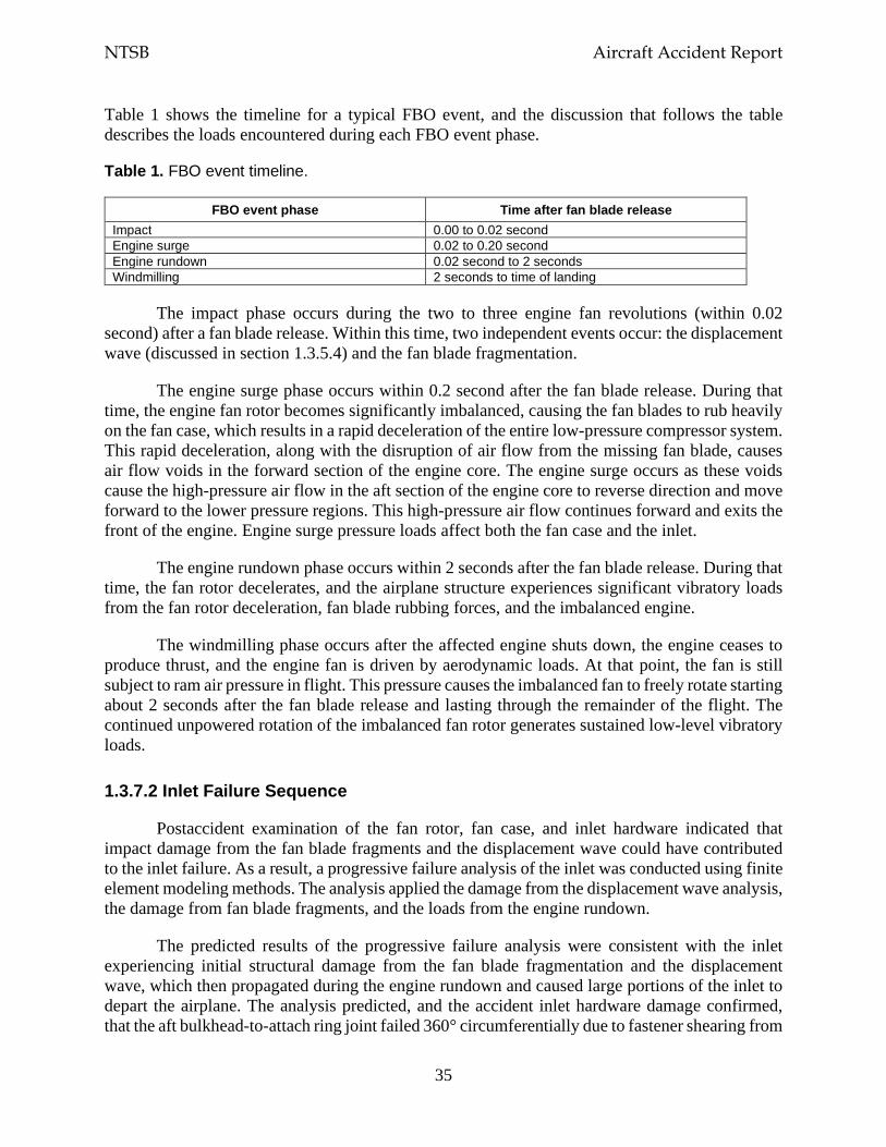
NTSB Aircraft Accident Report
35
Table 1 shows the timeline for a typical FBO event, and the discussion that follows the table describes the loads encountered during each FBO event phase.
Table 1. FBO event timeline.
FBO event phase Time after fan blade release Impact 0.00 to 0.02 second Engine surge 0.02 to 0.20 second Engine rundown 0.02 second to 2 seconds Windmilling 2 seconds to time of landing
The impact phase occurs during the two to three engine fan revolutions (within 0.02 second) after a fan blade release. Within this time, two independent events occur: the displacement wave (discussed in section 1.3.5.4) and the fan blade fragmentation.
The engine surge phase occurs within 0.2 second after the fan blade release. During that time, the engine fan rotor becomes significantly imbalanced, causing the fan blades to rub heavily on the fan case, which results in a rapid deceleration of the entire low-pressure compressor system. This rapid deceleration, along with the disruption of air flow from the missing fan blade, causes air flow voids in the forward section of the engine core. The engine surge occurs as these voids cause the high-pressure air flow in the aft section of the engine core to reverse direction and move forward to the lower pressure regions. This high-pressure air flow continues forward and exits the front of the engine. Engine surge pressure loads affect both the fan case and the inlet.
The engine rundown phase occurs within 2 seconds after the fan blade release. During that time, the fan rotor decelerates, and the airplane structure experiences significant vibratory loads from the fan rotor deceleration, fan blade rubbing forces, and the imbalanced engine.
The windmilling phase occurs after the affected engine shuts down, the engine ceases to produce thrust, and the engine fan is driven by aerodynamic loads. At that point, the fan is still subject to ram air pressure in flight. This pressure causes the imbalanced fan to freely rotate starting about 2 seconds after the fan blade release and lasting through the remainder of the flight. The continued unpowered rotation of the imbalanced fan rotor generates sustained low-level vibratory loads.
1.3.7.2 Inlet Failure Sequence
Postaccident examination of the fan rotor, fan case, and inlet hardware indicated that impact damage from the fan blade fragments and the displacement wave could have contributed to the inlet failure. As a result, a progressive failure analysis of the inlet was conducted using finite element modeling methods. The analysis applied the damage from the displacement wave analysis, the damage from fan blade fragments, and the loads from the engine rundown.
The predicted results of the progressive failure analysis were consistent with the inlet experiencing initial structural damage from the fan blade fragmentation and the displacement wave, which then propagated during the engine rundown and caused large portions of the inlet to depart the airplane. The analysis predicted, and the accident inlet hardware damage confirmed, that the aft bulkhead-to-attach ring joint failed 360° circumferentially due to fastener shearing from
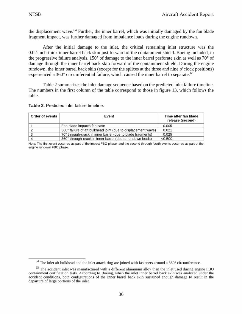
NTSB Aircraft Accident Report
36
the displacement wave.64 Further, the inner barrel, which was initially damaged by the fan blade fragment impact, was further damaged from imbalance loads during the engine rundown.
After the initial damage to the inlet, the critical remaining inlet structure was the 0.02-inch-thick inner barrel back skin just forward of the containment shield. Boeing included, in the progressive failure analysis, 150° of damage to the inner barrel perforate skin as well as 70° of damage through the inner barrel back skin forward of the containment shield. During the engine rundown, the inner barrel back skin (except for the splices at the three and nine o’clock positions) experienced a 360° circumferential failure, which caused the inner barrel to separate.65
Table 2 summarizes the inlet damage sequence based on the predicted inlet failure timeline. The numbers in the first column of the table correspond to those in figure 13, which follows the table.
Table 2. Predicted inlet failure timeline.
Order of events Event Time after fan blade release (second)
1 Fan blade impacts fan case 0.005 2 360° failure of aft bulkhead joint (due to displacement wave) 0.021 3 70° through-crack in inner barrel (due to blade fragments) 0.025 4 360° through-crack in inner barrel (due to rundown loads) <0.500
Note: The first event occurred as part of the impact FBO phase, and the second through fourth events occurred as part of the engine rundown FBO phase.
64 The inlet aft bulkhead and the inlet attach ring are joined with fasteners around a 360° circumference. 65 The accident inlet was manufactured with a different aluminum alloy than the inlet used during engine FBO
containment certification tests. According to Boeing, when the inlet inner barrel back skin was analyzed under the accident conditions, both configurations of the inner barrel back skin sustained enough damage to result in the departure of large portions of the inlet.
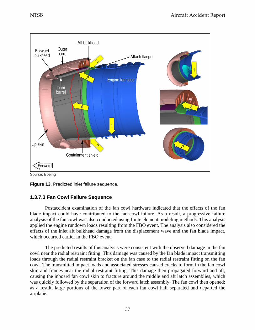
NTSB Aircraft Accident Report
37
Source: Boeing
Figure 13. Predicted inlet failure sequence.
1.3.7.3 Fan Cowl Failure Sequence
Postaccident examination of the fan cowl hardware indicated that the effects of the fan blade impact could have contributed to the fan cowl failure. As a result, a progressive failure analysis of the fan cowl was also conducted using finite element modeling methods. This analysis applied the engine rundown loads resulting from the FBO event. The analysis also considered the effects of the inlet aft bulkhead damage from the displacement wave and the fan blade impact, which occurred earlier in the FBO event.
The predicted results of this analysis were consistent with the observed damage in the fan cowl near the radial restraint fitting. This damage was caused by the fan blade impact transmitting loads through the radial restraint bracket on the fan case to the radial restraint fitting on the fan cowl. The transmitted impact loads and associated stresses caused cracks to form in the fan cowl skin and frames near the radial restraint fitting. This damage then propagated forward and aft, causing the inboard fan cowl skin to fracture around the middle and aft latch assemblies, which was quickly followed by the separation of the forward latch assembly. The fan cowl then opened; as a result, large portions of the lower part of each fan cowl half separated and departed the airplane.
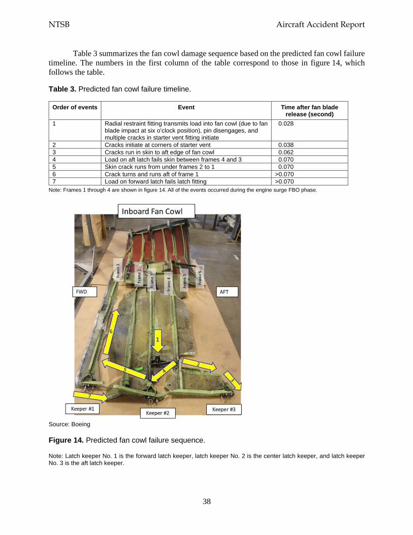
NTSB Aircraft Accident Report
38
Table 3 summarizes the fan cowl damage sequence based on the predicted fan cowl failure timeline. The numbers in the first column of the table correspond to those in figure 14, which follows the table.
Table 3. Predicted fan cowl failure timeline.
Order of events Event Time after fan blade release (second)
1 Radial restraint fitting transmits load into fan cowl (due to fan blade impact at six o’clock position), pin disengages, and multiple cracks in starter vent fitting initiate
0.028
2 Cracks initiate at corners of starter vent 0.038 3 Cracks run in skin to aft edge of fan cowl 0.062 4 Load on aft latch fails skin between frames 4 and 3 0.070 5 Skin crack runs from under frames 2 to 1 0.070 6 Crack turns and runs aft of frame 1 >0.070 7 Load on forward latch fails latch fitting >0.070
Note: Frames 1 through 4 are shown in figure 14. All of the events occurred during the engine surge FBO phase.
Source: Boeing
Figure 14. Predicted fan cowl failure sequence.
Note: Latch keeper No. 1 is the forward latch keeper, latch keeper No. 2 is the center latch keeper, and latch keeper No. 3 is the aft latch keeper.
NTSB Aircraft Accident Report
39
1.4 Meteorological Information
The automated surface observing system (ASOS) at PHL reported the following conditions at 1054 (about 26 minutes before the airplane landed): wind from 290° at 18 knots with gusts to 27 knots, visibility 10 miles or greater, broken ceiling at 4,800 ft above ground level (agl) and broken clouds at 8,000 ft agl, temperature 45°F, dew point 25°F, and altimeter setting 29.75 inches of mercury. At 1154 (about 34 minutes after the airplane landed), the ASOS reported the following conditions: wind from 270° at 16 knots with gusts to 21 knots, visibility 10 miles or greater, broken ceiling at 4,900 ft agl and overcast skies at 8,000 ft agl, temperature 45°F, dew point 25°F, and altimeter setting 29.73 inches of mercury. These observations indicated that visual flight rules conditions prevailed with a gusty surface wind from the west.
The NTSB reviewed pilot reports within 100 miles of the engine failure location, during the time period from about 2 hours before the accident to about 1 hour after the accident, and for altitudes above 10,000 ft. This review found no reports of turbulence or other significant weather conditions. No SIGMETs (Significant Meteorological Information) or center weather advisories were valid for the engine failure location at the time of the accident. An AIRMET (Airmen’s Meteorological Information) that was valid for the engine failure location at the time of the accident forecast moderate turbulence between flight levels 240 and 410 from 1045 to 1700.
1.5 Airport Information
According to measurements that the NTSB made using Google Earth, at the time of the engine failure, the airplane was 29 nautical miles (nm) from MDT and 57 nm from PHL. The FAA categorized MDT and PHL as class I airports, which allowed them to serve scheduled air carrier operations with aircraft that have 31 or more seats.66 MDT had one runway, 13/31, which was 10,001 ft long and 200 ft wide. PHL had four runways; the longest runway, 9R/27L, was 12,000 ft long and 200 ft wide. (The accident airplane landed on runway 27L at PHL)
The FAA also categorized the ARFF capabilities required for an airport, including the number of vehicles and amounts of water and firefighting chemicals required for the airport (as specified in 14 CFR 139.317, Aircraft Rescue and Firefighting: Equipment and Agents). Section 139.315, Aircraft Rescue and Firefighting: Index Determination, stated that an airport’s ARFF index was calculated based on the length of the air carrier aircraft serviced by the airport and the average number of daily departures of air carrier aircraft at the airport. The ARFF indexes ranged from A to E, with index E having the highest level of ARFF capabilities.
PHL was categorized as ARFF index E, which meant that the airport was required to have at least three vehicles with a minimum total quantity (among the three vehicles) of 6,000 gallons of water available for foam production along with additional firefighting chemical agents. MDT was categorized as ARFF index B, which meant that the airport was required to have one or two
66 The FAA defined four classes of airports, I through IV, that are certificated under 14 CFR Part 139. The FAA
defined a class I airport as “an airport certificated to serve scheduled operations of large air carrier aircraft [designed for at least 31 passenger seats] that can also serve unscheduled passenger operations of large air carrier aircraft and/or scheduled operations of small air carrier aircraft [designed for more than 9 passenger seats but less than 31 passenger seats].”
NTSB Aircraft Accident Report
40
vehicles with a minimum total quantity (among the vehicles) of 1,500 gallons of water for foam production and the same firefighting chemical agents as an index E airport.
1.6 Flight Recorders
The airplane was equipped with a Honeywell 6022 solid-state CVR. The CVR contains a two-channel digital audio recording of at least the last 2 hours of operation. One channel combines three audio panel sources—the captain, the first officer, and the observer—and the other channel is the cockpit area microphone. The CVR also contains a three-channel digital audio recording of the last 30 minutes of operation. The three channels are the individual audio panels for the captain, the first officer, and the observer. Each of the CVR channels contained either excellent- or good-quality audio information, and the data were extracted normally. A transcript was prepared of the recording, which began at 1052:57 (as the airplane was climbing to flight level 220) and ended at 1257:57 (after PHL ground crew personnel repositioned the airplane). Appendix B contains the CVR transcript and descriptions of excellent- and good-quality audio.
The airplane was also equipped with a Honeywell 4700 256 wps solid-state FDR. The recorder was in good condition, and the data were extracted normally. About 27 hours of operational data were retained on the recording medium, including about 53 minutes of data from the accident flight, from about 1030 to 1123.
1.7 Survival Aspects
The airplane was configured with 143 passenger seats; 2 flight crew seats; 2 cockpit observer seats; and 4 flight attendant jumpseats on double retractable seat sets, with two flight attendant aft-facing jumpseats in the forward cabin and two flight attendant forward-facing jumpseats in the aft cabin.67 The airplane had six emergency exits—four floor-level door exits and two overwing window exits. The airplane had 24 rows of passenger seats on the left and right sides of the airplane, all of which had six passenger seats in two triple seat sets (ABC and DEF) except for row 11, which had two passenger seats (BC) located next to the left overwing exit. The fatally injured passenger was in seat 14A, which was located next to the cabin sidewall on the left side of the airplane.68
1.7.1 Cabin Window
The exterior cabin window by seat 14A measured 10 1/2 inches horizontally, 14 3/8 inches vertically, and 15 inches diagonally, as shown in figure 15. Ten spring clips surrounded the window frame. The window components also included an acrylic outer pane, an acrylic middle
67 One of the 144 passengers, a SWA employee, was seated in a jumpseat in the aft cabin. 68 The City of Philadelphia Medical Examiner’s Office performed an autopsy on the fatally injured passenger.
The autopsy report showed that the passenger’s cause of death was “blunt force trauma of the head, neck, and torso.” These injuries were not survivable.
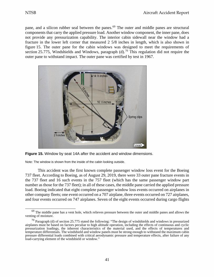
NTSB Aircraft Accident Report
41
pane, and a silicon rubber seal between the panes.69 The outer and middle panes are structural components that carry the applied pressure load. Another window component, the inner pane, does not provide any pressurization capability. The interior cabin sidewall near the window had a fracture in the lower left corner that measured 2 5/8 inches in length, which is also shown in figure 15. The outer pane for the cabin windows was designed to meet the requirements of section 25.775, Windshields and Windows, paragraph (d).70 This regulation did not require the outer pane to withstand impact. The outer pane was certified by test in 1967.
Figure 15. Window by seat 14A after the accident and window dimensions.
Note: The window is shown from the inside of the cabin looking outside.
This accident was the first known complete passenger window loss event for the Boeing 737 fleet. According to Boeing, as of August 29, 2019, there were 33 outer pane fracture events in the 737 fleet and 16 such events in the 757 fleet (which has the same passenger window part number as those for the 737 fleet); in all of these cases, the middle pane carried the applied pressure load. Boeing indicated that eight complete passenger window loss events occurred on airplanes in other company fleets; one event occurred on a 707 airplane, three events occurred on 727 airplanes, and four events occurred on 747 airplanes. Seven of the eight events occurred during cargo flights
69 The middle pane has a vent hole, which relieves pressure between the outer and middle panes and allows the
venting of moisture. 70 Paragraph (d) of section 25.775 stated the following: “The design of windshields and windows in pressurized
airplanes must be based on factors peculiar to high altitude operation, including the effects of continuous and cyclic pressurization loadings, the inherent characteristics of the material used, and the effects of temperatures and temperature differentials. The windshield and window panels must be strong enough to withstand the maximum cabin pressure differential loads combined with critical aerodynamic pressure and temperature effects, after failure of any load-carrying element of the windshield or window.”
NTSB Aircraft Accident Report
42
or aboard airplanes with empty passenger cabins with no injuries reported. The eighth event involved a 747 passenger window that departed the airplane at an altitude of 12,500 ft. No passenger was seated adjacent to the window, and no injuries were reported.
1.7.2 Cabin Pressurization Control System
According to Boeing’s 737-600/700/800/900 Aircraft Maintenance Manual, the airplane’s air conditioning packs provide air to the cabin, and the pressurization control system maintains a safe cabin altitude at all airplane altitudes.71 As stated in section 1.1, for all pressurized flights, the cabin pressure altitude is determined by a pressure schedule that keeps the cabin altitude below 8,000 ft, which enables the flight crew to safely operate the airplane and protects the airplane occupants from the effects of hypoxia (oxygen starvation). The cabin pressure altitude increases as the airplane’s altitude increases; the cabin pressure altitude decreases as the airplane’s altitude decreases.
The cabin altitude warning switch, located on the ceiling in the forward electronic equipment compartment, closes when the cabin altitude has reached 10,000 ft pressure altitude ± 1,000 ft (9,000 to 11,000 ft). When the cabin altitude warning switch closes, an aural warning annunciates as “an intermittent beep alarm,” and the red CABIN ALTITUDE indicator lights on the captain’s and the first officer’s instrument panels illuminate. When the cabin altitude returns to a level that is below 10,000 ft, the cabin altitude warning switch opens, the indicator lights no longer illuminate, and the warning circuit resets. An ALT HORN CUTOUT switch on the cabin altitude panel is used to silence the alarm.
For the accident flight, Boeing calculated that the cabin pressure would have been 5,773 ft as the airplane was climbing through an altitude of 32,600 ft.72 Among the information that the active cabin pressure controller logged after the engine failure was a 10,000-ft cabin altitude status message at 32,610 ft and a 13,500-ft cabin altitude status message at 32,554 ft, indicating that the cabin altitude was increasing as the airplane’s altitude was decreasing.
The cabin pressure controller recorded the 10,000-ft cabin altitude status message when the cabin altitude was 10,661 ft. FDR data showed that the cabin altitude warning parameter, which was sampled once per second, transitioned from no warning to warning between about 1103:38 and 1103:39. The CVR recorded the sound of the cabin altitude warning horn at 1103:39, which was about 6 seconds after sounds consistent with the engine failure were recorded on the CVR. The SWA Cabin Altitude Warning or Rapid Depressurization checklist showed that flight crewmembers were required to “don oxygen masks” if the cabin altitude warning horn sounded, and the company’s Emergency Descent checklist indicated that the “flight deck crew must use oxygen when cabin altitude is above 10,000 feet.”
71 The air conditioning system uses bleed air from the engines to provide pressurized air to the cabin. 72 Neither the FDR nor the cabin pressurization control system continuously records cabin altitude, so Boeing
calculated the cabin altitude assuming normal bleed and air conditioning system operation and nominal air leakage through openings in the fuselage.
NTSB Aircraft Accident Report
43
As stated in the next section, oxygen masks that provided supplemental oxygen to the flight attendants and the passengers were designed to deploy automatically when the cabin altitude reached 14,000 ft. The cabin altitude was 14,067 ft when the cabin pressure controller recorded the 13,500-ft cabin altitude status message. There is no parameter on the FDR that directly records when the oxygen masks have deployed.73
1.7.3 Supplemental Oxygen System
A supplemental oxygen system was located above the flight attendant jumpseats and in the passenger service unit above each of the 48 seat sets on the airplane.74 The system was designed to provide oxygen to flight attendants and passengers if a depressurization event occurred. (The flight crew received supplemental oxygen from a different source.)
The supplemental oxygen system in the passenger service unit consisted of an oxygen generator, a lanyard-based activation system, a distribution manifold with flexible mask supply tubing, and four masks.75 The four masks were designed to deploy when the oxygen mask compartment door opened, which occurred either automatically if the cabin altitude reached 14,000 ft or manually by the flight crew using a guarded switch on a cockpit overhead panel. Oxygen generation would begin after a passenger pulled a mask toward his/her face, causing the firing pin (connected to the lanyard) to release. Once the firing pin released, oxygen would flow through the tubing into a reservoir bag attached to the mask. The oxygen generators for all 48 seat sets were found activated.
1.7.4 Flight Attendant Postaccident Interviews
At the time of the engine failure, flight attendant A was in the forward lavatory, flight attendant B was in the aft galley preparing for in-flight service, and flight attendant C was in the cabin near row 5. All three flight attendants heard a loud noise and felt the airplane shaking. Flight attendants A and C immediately went to the forward jumpseat (where they were stationed), sat down, fastened their restraints, and put on oxygen masks that had deployed from above the jumpseat. Flight attendant A reported that debris was flying around in the cabin. Flight attendant B did not notice that the oxygen masks had deployed until a company employee, who was seated on the aft jumpseat, alerted her. She then sat down on the aft jumpseat (where she was stationed) and put on an oxygen mask.
The flight attendants then retrieved the two portable oxygen bottles in both the forward and aft entry stowage compartments. All three flight attendants donned portable oxygen bottles and moved into the cabin to check on the passengers. Flight attendant A noted that some passengers
73 Even though the FDR does not directly record when the flight attendant and passenger oxygen masks have
deployed, the master caution alert is linked to oxygen mask deployment. During the accident flight, the master caution alert had previously activated due to the engine failure; thus, the timing of this alert could not be used to determine when the oxygen masks deployed.
74 (a) The passenger service unit also included individually controlled reading lights, air vents, flight attendant call buttons, and a speaker to hear PA announcements. (b) Masks were also located in service units in the forward and aft lavatories.
75 There was one extra mask for each seat set. According to section 25.1447, Equipment Standards for Oxygen Dispensing Units, the number of oxygen masks needs to exceed the number of seats by at least 10%.
NTSB Aircraft Accident Report
44
were wearing the mask over their mouth only (and not over both their nose and mouth as intended). Flight attendant A checked to ensure that each passenger was receiving oxygen and stopped at row 8 to help a female passenger with a lap child.
Flight attendant C also walked through the cabin, telling passengers that they should breathe normally through their masks and that they were receiving oxygen even if the oxygen bag did not inflate. When flight attendant C reached row 14, she saw that the head, upper torso, and arms of the passenger seated in 14A had been pulled outside the airplane through the window. The passenger’s seat belt was buckled. Flight attendant C grabbed onto the passenger and, with assistance from flight attendant A, tried to bring the passenger back into the airplane, but flight attendant A reported that they could not get the passenger back into the airplane by themselves because of the pressure and the altitude. Two male passengers (in seats 8D and 13D) offered to help; they were able to pull the passenger back into the airplane and laid the injured passenger across seats 14ABC.76
Flight attendant B moved through the cabin to check on passengers. She did not notice any passengers whose masks were on incorrectly and was not aware of any masks that were not working. She did not know about the window breach until she saw the other flight attendants and some passengers attending to a passenger in row 14. She stated that the two other passengers from row 14 (seats 14B and 14C) had moved to the aft galley. When flight attendant B reached the aft galley, she heard the interphone chime and answered the phone but could not hear anything because of the “very loud” noise in the cabin.
Flight attendant C went to the aft galley to use the interphone to alert the pilots about the condition of the passenger in seat 14A and make a PA announcement requesting medical assistance from any qualified passenger aboard. The passenger in seat 8D (a paramedic) and the passenger in seat 11C (a nurse) started CPR compressions on the injured passenger, and flight attendant A retrieved, from the forward right overhead bin, the automated external defibrillator (AED) and the fast response kit, which was secured to the AED and contained tools and supplies needed to use the AED as well as a CPR mask.77
Flight attendants B and C stated that they did not hear any announcement from the flight crew when the airplane reached a safe altitude to breathe without masks, but all three flight attendants recalled a flight crew announcement indicating that the airplane would be landing at PHL. Flight attendant A stated that she did not have time to return to her jumpseat for landing, so she sat on the aisle floor near row 4 or 5, and seated passengers held her down. Flight attendant B sat on the floor in the aft galley with seated passengers holding her down during landing. (The aft jumpseat, where flight attendant B was stationed, was occupied by a passenger from row 14 and the SWA company employee. The other passenger from row 14 was seated on the aft galley floor.) Flight attendant C also sat on the floor in the aft galley during landing. (She did not indicate
76 Before assisting flight attendant C with her efforts to pull the passenger back into the airplane, flight attendant
A instructed the passengers in seats 14B and 14C to move out of the row “in case a bigger hole happened around the window.”
77 During postaccident interviews, the passengers in seats 8D and 11C reported that another passenger (who they stated was either a physician or a medical school graduate) was giving CPR breaths to the injured passenger while they performed the compressions.
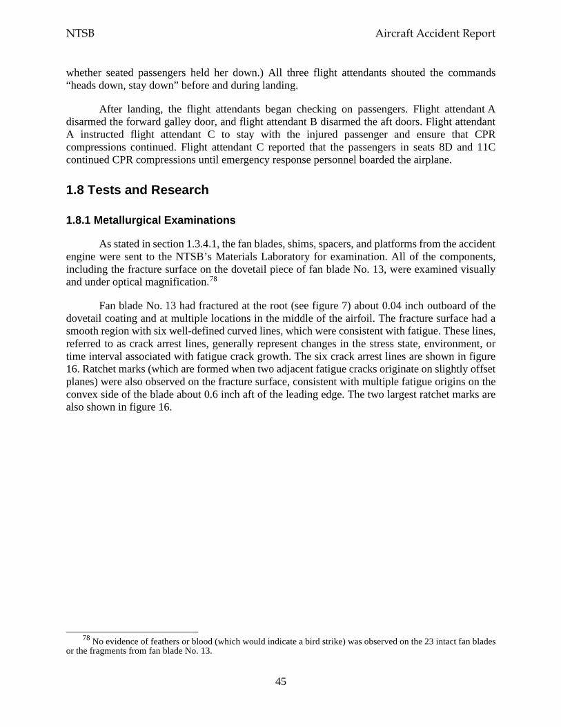
NTSB Aircraft Accident Report
45
whether seated passengers held her down.) All three flight attendants shouted the commands “heads down, stay down” before and during landing.
After landing, the flight attendants began checking on passengers. Flight attendant A disarmed the forward galley door, and flight attendant B disarmed the aft doors. Flight attendant A instructed flight attendant C to stay with the injured passenger and ensure that CPR compressions continued. Flight attendant C reported that the passengers in seats 8D and 11C continued CPR compressions until emergency response personnel boarded the airplane.
1.8 Tests and Research
1.8.1 Metallurgical Examinations
As stated in section 1.3.4.1, the fan blades, shims, spacers, and platforms from the accident engine were sent to the NTSB’s Materials Laboratory for examination. All of the components, including the fracture surface on the dovetail piece of fan blade No. 13, were examined visually and under optical magnification.78
Fan blade No. 13 had fractured at the root (see figure 7) about 0.04 inch outboard of the dovetail coating and at multiple locations in the middle of the airfoil. The fracture surface had a smooth region with six well-defined curved lines, which were consistent with fatigue. These lines, referred to as crack arrest lines, generally represent changes in the stress state, environment, or time interval associated with fatigue crack growth. The six crack arrest lines are shown in figure 16. Ratchet marks (which are formed when two adjacent fatigue cracks originate on slightly offset planes) were also observed on the fracture surface, consistent with multiple fatigue origins on the convex side of the blade about 0.6 inch aft of the leading edge. The two largest ratchet marks are also shown in figure 16.
78 No evidence of feathers or blood (which would indicate a bird strike) was observed on the 23 intact fan blades
or the fragments from fan blade No. 13.
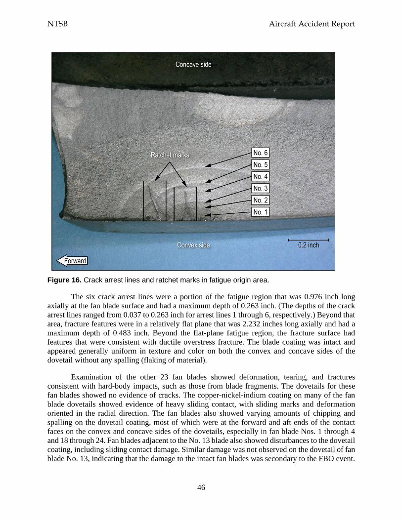
NTSB Aircraft Accident Report
46
Figure 16. Crack arrest lines and ratchet marks in fatigue origin area.
The six crack arrest lines were a portion of the fatigue region that was 0.976 inch long axially at the fan blade surface and had a maximum depth of 0.263 inch. (The depths of the crack arrest lines ranged from 0.037 to 0.263 inch for arrest lines 1 through 6, respectively.) Beyond that area, fracture features were in a relatively flat plane that was 2.232 inches long axially and had a maximum depth of 0.483 inch. Beyond the flat-plane fatigue region, the fracture surface had features that were consistent with ductile overstress fracture. The blade coating was intact and appeared generally uniform in texture and color on both the convex and concave sides of the dovetail without any spalling (flaking of material).
Examination of the other 23 fan blades showed deformation, tearing, and fractures consistent with hard-body impacts, such as those from blade fragments. The dovetails for these fan blades showed no evidence of cracks. The copper-nickel-indium coating on many of the fan blade dovetails showed evidence of heavy sliding contact, with sliding marks and deformation oriented in the radial direction. The fan blades also showed varying amounts of chipping and spalling on the dovetail coating, most of which were at the forward and aft ends of the contact faces on the convex and concave sides of the dovetails, especially in fan blade Nos. 1 through 4 and 18 through 24. Fan blades adjacent to the No. 13 blade also showed disturbances to the dovetail coating, including sliding contact damage. Similar damage was not observed on the dovetail of fan blade No. 13, indicating that the damage to the intact fan blades was secondary to the FBO event.
NTSB Aircraft Accident Report
47
Most fan blade shims were intact, but the shims for blade Nos. 11 and 12 were cracked. Specifically, the shim for blade No. 11 was cracked at the outboard edge of the contact face on the concave side of the shim, and the shim for blade No. 12 (which trailed fan blade No. 13) was cracked along the inboard edge of the contact face on both sides of the shim.
Many of the fan blade platforms showed cracks, deformation, and fractures at the sides contacting the blade airfoils. The fan blade platform for the No. 12 blade had fractured, and most of the platform was missing. The fracture surfaces of the fan blade platforms were consistent with overstress. The spacers for each fan blade were present and were intact. Some fretting contact damage was observed on the forward face of the spacers.
Additional examinations of fan blade No. 13
The fracture surface of fan blade No. 13 was also examined using a scanning electron microscope (SEM). The crack arrest lines that were visible under optical magnification (as shown in figure 16) were also generally visible in SEM images. Secondary crack features that were consistent with additional fatigue cracks were observed on the blade surface adjacent to the fracture origin area.
At higher SEM magnifications, striations consistent with low-cycle fatigue crack growth were observed on the fracture surface.79 The striation spacing generally became larger as the depth of the crack increased and as the crack advanced toward the arrest lines. Immediately beyond the crack arrest lines, the striation spacing changed abruptly; the spacing between striations was shorter than the spacing before the arrest lines, which was consistent with a temporary reduction in crack growth rate after each arrest line had formed.
The fracture surface in the area of stable fatigue crack growth was examined to estimate the number of striations in that area. One striation is usually associated with one flight cycle; thus, the total number of flight cycles associated with crack growth is about equal to the estimated number of striations. For crack growth from a depth of 0.0005 inch to the crack arrest line with the maximum depth of 0.263 inch (arrest line 6), the number of striations was estimated to be 18,400.80
The number of flight cycles between six of the last seven relubrications (which ranged from 1,255 to 2,201 cycles) was similar to the estimated number of cycles accumulated between crack arrest lines, which ranged from 1,608 to 2,539 cycles.81 The number of cycles for the crack growth beyond arrest line 6 was estimated from the number of flight cycles accumulated since the last fan blade relubrication, which occurred in June 2017. Between that time and the time of the accident, the engine and the fan blade set accumulated 1,704 cycles.
A crack arrest line would be expected on a fracture surface after a relubrication or an overhaul because of the change to the stress state. (In this case, relubrication changes the contact
79 Striations are linear features on a fatigue fracture surface that indicate how far a crack advanced with each
stress cycle. 80 The NTSB used 0.0005 inch as the starting depth because the number of striations could not be fully resolved
closer to the crack origin. 81 The range of cycles between the six relubrications excluded the 98 cycles that the fan blade set had accumulated
between the July 30 and August 17, 2015, relubrications.
NTSB Aircraft Accident Report
48
friction at the dovetail.) Thus, crack arrest line 6 on fan blade No. 13 was assumed to be associated with the last blade relubrication, and the crack growth beyond crack arrest line 6 was assumed to be associated with the 1,704 cycles accumulated since the last relubrication. This number of cycles was added to the estimated 18,400 cycles associated with crack growth from 0.0005 to 0.263 inch (the latter of which was the depth of crack arrest line 6), and the result showed that the estimated total number of cycles from a depth of 0.0005 inch to blade failure was about 20,000 cycles.
In addition, the estimated total cycles of crack growth from the crack depth associated with crack arrest line 2 (0.068 inch) to fan blade failure (0.483 inch) was about 10,000 cycles. This number of cycles matched closely (within 10%) with the number of cycles (10,712) since the time of the fan blade set’s last overhaul in October 2012, indicating that the fan blade crack had likely initiated before the overhaul. The estimated total number of cycles from a depth of 0.0005 inch to fan blade failure (0.483 inch) was about 20,000 cycles; thus, crack arrest line 2 had accumulated about 10,000 cycles of growth from a depth of 0.0005 to 0.068 inch.
A metallographic examination was also conducted using transverse cross-section samples from the dovetail piece of fan blade No. 13. The samples were cut from the overstress regions at the middle of the blade and near the trailing (aft) end of the dovetail contact face. The cross-section samples were polished and then etched to reveal the blade microstructure, which was consistent with the expected microstructure for the specified material. No material or manufacturing anomalies were observed on the surfaces.
Nondestructive inspections of intact fan blades
Nondestructive inspections were conducted on 22 of the 23 intact fan blades using ultrasonic inspection, FPI, and eddy current inspection (ECI) procedures at the GE Engineering Materials Systems Laboratory in Evendale, Ohio, and the Safran Aircraft Engines Failure Analysis Laboratory in Moissy-Cramayel, France, to identify any cracks on the concave and convex sides of the fan blade roots.82 (Blade No. 20 was examined on scene and was excluded from these additional inspections because that blade had been sectioned for SEM and metallographic examinations.)83 The inspections were consistent with the CFM-recommended ultrasonic inspection procedures used during fan blade relubrications (see SB 72-1033 in section 1.10.2.3) and the FPI and ECI procedures used during fan blade overhauls. No indications of cracks were found on the inspected fan blades (Nos. 1 through 12, 14 through 19, and 21 through 24).
82 An ECI is a nondestructive inspection method that detects cracks at or near the surface of a part. Section 1.10.1
provides additional information about an ECI. 83 As part of the on-scene investigation, each intact blade received an ultrasonic inspection. None of the intact
blades had an ultrasonic signal response that exceeded CFM’s crack indication threshold (which was established to provide sufficient reliability for detecting a crack and minimize false-positive indications). Blade No. 20 had one of the highest signal responses (about one-half of the threshold level), so that blade was selected for SEM examination to determine whether it had any evidence of crack features. Isolated microcrack features were observed. (A microcrack is a microscopic crack that is usually visible only at magnifications of at least 50 times.) Metallographic examination of a cross-section at the convex surface of the blade showed one microcrack that had a depth of 0.001 inch. The microcrack was located 0.61 inch from the root end face.
NTSB Aircraft Accident Report
49
Residual stress measurements
Residual stress measurements were made, in the radial and/or longitudinal (axial) directions, on fan blade Nos. 13 and 20 at Lambda Technologies in Cincinnati, Ohio, and fan blade Nos. 3, 12, 23, and 24 at the Safran Materials and Processes Laboratory in Evry Corbeil and Vernon, France. The residual stress measurements were performed using x-ray diffraction on multiple areas of the dovetail surfaces and at varying depths up to 0.0083 inch.84 The measurements were compared with reference residual stress depth profile data (provided by Safran) for fan blades that were shot-peened in accordance with specified parameters.
The results of the residual stress measurements showed abnormal residual stress profiles, including residual tension near the surface, in one or more locations on each of the intact fan blades (Nos. 3, 12, 20, 23, and 24) compared with the reference residual stress depth profile data. A total of 14 measurements were made for these fan blades, and 11 of these measurements showed that the minimum residual stress value was higher (less compressive) than the expected minimum value. Residual stress measurements were taken at two locations on fractured fan blade No. 13, and the measurements showed residual stress profiles that were similar to the expected profile
Although fan blade No. 13 had a normal residual stress profile, crack growth estimates developed during fractographic (optical and SEM) examinations showed that the blade had been overhauled after the crack had initiated. As part of the overhaul, fan blade No. 13 was shot-peened (along with all of the other fan blades in the set). The shot-peening process resets the residual stress state and removes any evidence of the relaxed residual stresses that appear to be associated with crack initiation, which could explain why the fan blade’s residual stress profile was similar to the reference residual stress profile. Even though all of the other fan blades in the set were also shot-peened during the overhaul, some of those blades experienced higher-than-normal stresses after the FBO event, resulting in the abnormal residual stress profiles for fan blade Nos. 3, 12, 20, 23, and 24.
Additional metallurgical examinations
Between the date of the accident and June 30, 2018, cracks were detected on four fan blades installed on separate engines through either an ECI during overhaul or an ultrasonic inspection as part of blade relubrication. All of the cracks were in the shot-peened area of the dovetail and were located between 0.552 and 0.598 inch radially from the fan blade root. These fan blades were sent to CFM for examination; afterward, two of the blades were examined at the GE Engineering Materials Systems facility, and the other two blades were examined at the Safran Aircraft Engines Failure Analysis Laboratory. Table 4 presents information about the four fan blades, and section 1.10.3 presents information about cracks found on other fan blades after June 2018.
84 The measurements for fan blades Nos. 13 and 20 were taken near the middle of the contact face on the convex
side about 0.5 inch and 2 inches from the leading edge. The measurements for fan blades Nos. 3, 12, 23, and 24 were taken near the outboard side of the contact face on the convex side about 0.5 inch and 2 inches from the leading edge and on the concave side about 1 inch forward of the fan blade axial retention slot. Before the measurements were taken, the coating on fan blade No. 13 was stripped. (The coating on the other fan blades had been stripped for previous postaccident examinations.)
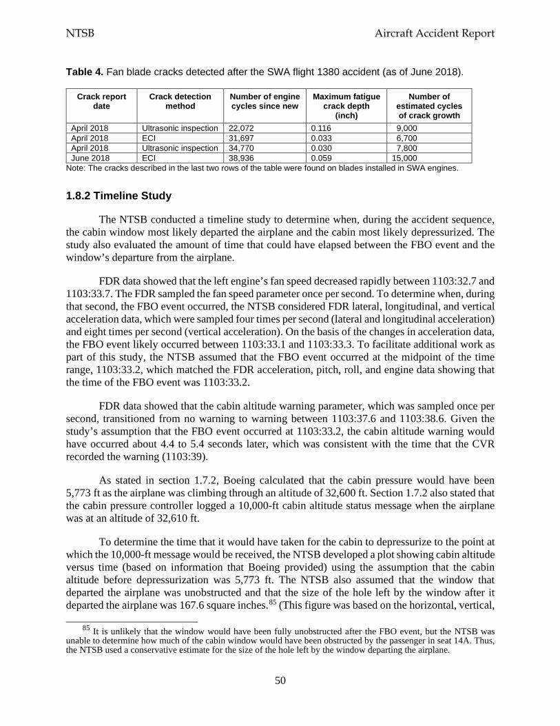
NTSB Aircraft Accident Report
50
Table 4. Fan blade cracks detected after the SWA flight 1380 accident (as of June 2018).
Crack report date
Crack detection method
Number of engine cycles since new
Maximum fatigue crack depth
(inch)
Number of estimated cycles of crack growth
April 2018 Ultrasonic inspection 22,072 0.116 9,000 April 2018 ECI 31,697 0.033 6,700 April 2018 Ultrasonic inspection 34,770 0.030 7,800 June 2018 ECI 38,936 0.059 15,000
Note: The cracks described in the last two rows of the table were found on blades installed in SWA engines.
1.8.2 Timeline Study
The NTSB conducted a timeline study to determine when, during the accident sequence, the cabin window most likely departed the airplane and the cabin most likely depressurized. The study also evaluated the amount of time that could have elapsed between the FBO event and the window’s departure from the airplane.
FDR data showed that the left engine’s fan speed decreased rapidly between 1103:32.7 and 1103:33.7. The FDR sampled the fan speed parameter once per second. To determine when, during that second, the FBO event occurred, the NTSB considered FDR lateral, longitudinal, and vertical acceleration data, which were sampled four times per second (lateral and longitudinal acceleration) and eight times per second (vertical acceleration). On the basis of the changes in acceleration data, the FBO event likely occurred between 1103:33.1 and 1103:33.3. To facilitate additional work as part of this study, the NTSB assumed that the FBO event occurred at the midpoint of the time range, 1103:33.2, which matched the FDR acceleration, pitch, roll, and engine data showing that the time of the FBO event was 1103:33.2.
FDR data showed that the cabin altitude warning parameter, which was sampled once per second, transitioned from no warning to warning between 1103:37.6 and 1103:38.6. Given the study’s assumption that the FBO event occurred at 1103:33.2, the cabin altitude warning would have occurred about 4.4 to 5.4 seconds later, which was consistent with the time that the CVR recorded the warning (1103:39).
As stated in section 1.7.2, Boeing calculated that the cabin pressure would have been 5,773 ft as the airplane was climbing through an altitude of 32,600 ft. Section 1.7.2 also stated that the cabin pressure controller logged a 10,000-ft cabin altitude status message when the airplane was at an altitude of 32,610 ft.
To determine the time that it would have taken for the cabin to depressurize to the point at which the 10,000-ft message would be received, the NTSB developed a plot showing cabin altitude versus time (based on information that Boeing provided) using the assumption that the cabin altitude before depressurization was 5,773 ft. The NTSB also assumed that the window that departed the airplane was unobstructed and that the size of the hole left by the window after it departed the airplane was 167.6 square inches.85 (This figure was based on the horizontal, vertical,
85 It is unlikely that the window would have been fully unobstructed after the FBO event, but the NTSB was
unable to determine how much of the cabin window would have been obstructed by the passenger in seat 14A. Thus, the NTSB used a conservative estimate for the size of the hole left by the window departing the airplane.
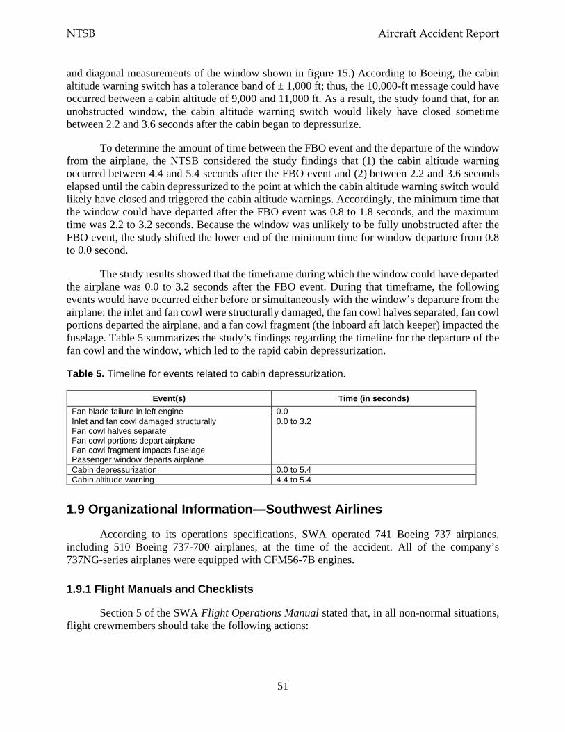
NTSB Aircraft Accident Report
51
and diagonal measurements of the window shown in figure 15.) According to Boeing, the cabin altitude warning switch has a tolerance band of ± 1,000 ft; thus, the 10,000-ft message could have occurred between a cabin altitude of 9,000 and 11,000 ft. As a result, the study found that, for an unobstructed window, the cabin altitude warning switch would likely have closed sometime between 2.2 and 3.6 seconds after the cabin began to depressurize.
To determine the amount of time between the FBO event and the departure of the window from the airplane, the NTSB considered the study findings that (1) the cabin altitude warning occurred between 4.4 and 5.4 seconds after the FBO event and (2) between 2.2 and 3.6 seconds elapsed until the cabin depressurized to the point at which the cabin altitude warning switch would likely have closed and triggered the cabin altitude warnings. Accordingly, the minimum time that the window could have departed after the FBO event was 0.8 to 1.8 seconds, and the maximum time was 2.2 to 3.2 seconds. Because the window was unlikely to be fully unobstructed after the FBO event, the study shifted the lower end of the minimum time for window departure from 0.8 to 0.0 second.
The study results showed that the timeframe during which the window could have departed the airplane was 0.0 to 3.2 seconds after the FBO event. During that timeframe, the following events would have occurred either before or simultaneously with the window’s departure from the airplane: the inlet and fan cowl were structurally damaged, the fan cowl halves separated, fan cowl portions departed the airplane, and a fan cowl fragment (the inboard aft latch keeper) impacted the fuselage. Table 5 summarizes the study’s findings regarding the timeline for the departure of the fan cowl and the window, which led to the rapid cabin depressurization.
Table 5. Timeline for events related to cabin depressurization.
Event(s) Time (in seconds) Fan blade failure in left engine 0.0 Inlet and fan cowl damaged structurally Fan cowl halves separate Fan cowl portions depart airplane Fan cowl fragment impacts fuselage Passenger window departs airplane
0.0 to 3.2
Cabin depressurization 0.0 to 5.4 Cabin altitude warning 4.4 to 5.4
1.9 Organizational Information—Southwest Airlines
According to its operations specifications, SWA operated 741 Boeing 737 airplanes, including 510 Boeing 737-700 airplanes, at the time of the accident. All of the company’s 737NG-series airplanes were equipped with CFM56-7B engines.
1.9.1 Flight Manuals and Checklists
Section 5 of the SWA Flight Operations Manual stated that, in all non-normal situations, flight crewmembers should take the following actions:
NTSB Aircraft Accident Report
52
• Maintain aircraft control • Analyze the problem • Take appropriate action • Maintain situational awareness
This information was also printed on the cover of the SWA Boeing 737NG QRH. Both flight crewmembers stated that they were focused on the first item on the list, maintaining aircraft control, during the emergency descent.
SWA had two printed flight deck resources for pilots to use during non-normal situations in flight: the QRH and the Quick Reference Card (QRC). The QRC was intended to assist flight crews in accomplishing specific items in non-normal checklists. The QRC listed the steps necessary to stabilize the situation and, if required, prompted the crew to complete the remainder of a non-normal checklist using the QRH.
Non-normal checklists contained immediate action items, quick reference items, and/or reference items. Immediate action items were time-critical steps that had to be committed to and accomplished from memory. Immediate action items were listed above a red dashed line on the QRC and in the QRH. Quick reference items were time-sensitive steps that were completed using the QRC; these steps were also included in the QRH. Quick reference items were listed above a black dashed line on the QRC and in the QRH. Reference items were actions or steps that were to be accomplished by using a non-normal checklist in the QRH.
The four non-normal checklists that applied to the circumstances of this accident were Engine Fire or Engine Severe Damage or Separation, One Engine Inoperative Landing, Cabin Altitude Warning or Rapid Depressurization, and Emergency Descent. The flight crew performed most of the Engine Fire or Engine Severe Damage checklist. Although the flight crew did not execute the other checklists using the standard checklist procedure (during which the crewmembers formally interact with each other to read the checklist and take the appropriate action), some of the items on the Cabin Altitude Warning or Rapid Depressurization and the Emergency Descent checklists were performed. The flight crew also performed the Before Landing checklist, which was a normal checklist. Each of these in-flight checklists is presented in sections 1.9.1.1 through 1.9.1.5.86
1.9.1.1 Engine Fire or Engine Severe Damage or Separation
According to SWA’s Boeing 737NG QRH, the Engine Fire or Engine Severe Damage or Separation checklist should be accomplished if an engine fire warning, airframe vibrations with abnormal engine indications, and/or an engine separation occur. The three-page checklist, which had 14 items, is shown in figure 17. The first five items on the checklist were considered to be quick reference (time-sensitive) items, as indicated by the dashed black line below the fifth item.
86 As stated in section 1.1.1, the flight crew performed the shutdown checklist after the airplane landed.
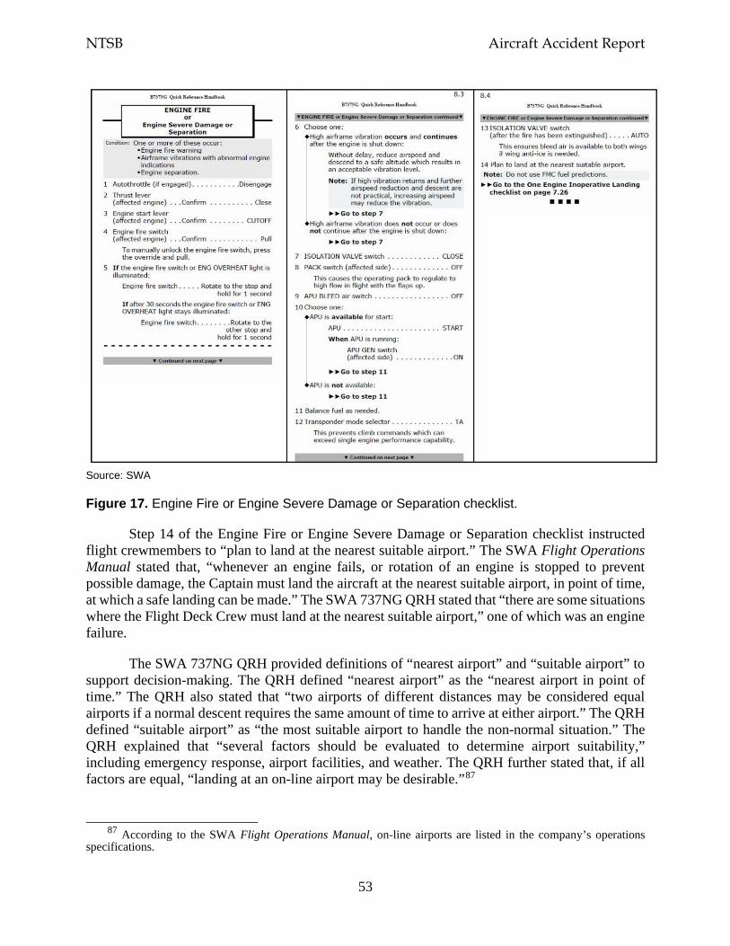
NTSB Aircraft Accident Report
53
Source: SWA
Figure 17. Engine Fire or Engine Severe Damage or Separation checklist.
Step 14 of the Engine Fire or Engine Severe Damage or Separation checklist instructed flight crewmembers to “plan to land at the nearest suitable airport.” The SWA Flight Operations Manual stated that, “whenever an engine fails, or rotation of an engine is stopped to prevent possible damage, the Captain must land the aircraft at the nearest suitable airport, in point of time, at which a safe landing can be made.” The SWA 737NG QRH stated that “there are some situations where the Flight Deck Crew must land at the nearest suitable airport,” one of which was an engine failure.
The SWA 737NG QRH provided definitions of “nearest airport” and “suitable airport” to support decision-making. The QRH defined “nearest airport” as the “nearest airport in point of time.” The QRH also stated that “two airports of different distances may be considered equal airports if a normal descent requires the same amount of time to arrive at either airport.” The QRH defined “suitable airport” as “the most suitable airport to handle the non-normal situation.” The QRH explained that “several factors should be evaluated to determine airport suitability,” including emergency response, airport facilities, and weather. The QRH further stated that, if all factors are equal, “landing at an on-line airport may be desirable.”87
87 According to the SWA Flight Operations Manual, on-line airports are listed in the company’s operations
specifications.
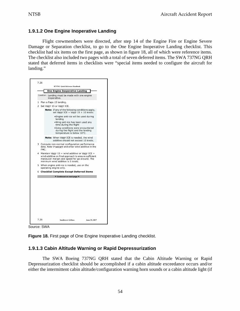
NTSB Aircraft Accident Report
54
1.9.1.2 One Engine Inoperative Landing
Flight crewmembers were directed, after step 14 of the Engine Fire or Engine Severe Damage or Separation checklist, to go to the One Engine Inoperative Landing checklist. This checklist had six items on the first page, as shown in figure 18, all of which were reference items. The checklist also included two pages with a total of seven deferred items. The SWA 737NG QRH stated that deferred items in checklists were “special items needed to configure the aircraft for landing.”
Source: SWA
Figure 18. First page of One Engine Inoperative Landing checklist.
1.9.1.3 Cabin Altitude Warning or Rapid Depressurization
The SWA Boeing 737NG QRH stated that the Cabin Altitude Warning or Rapid Depressurization checklist should be accomplished if a cabin altitude exceedance occurs and/or either the intermittent cabin altitude/configuration warning horn sounds or a cabin altitude light (if
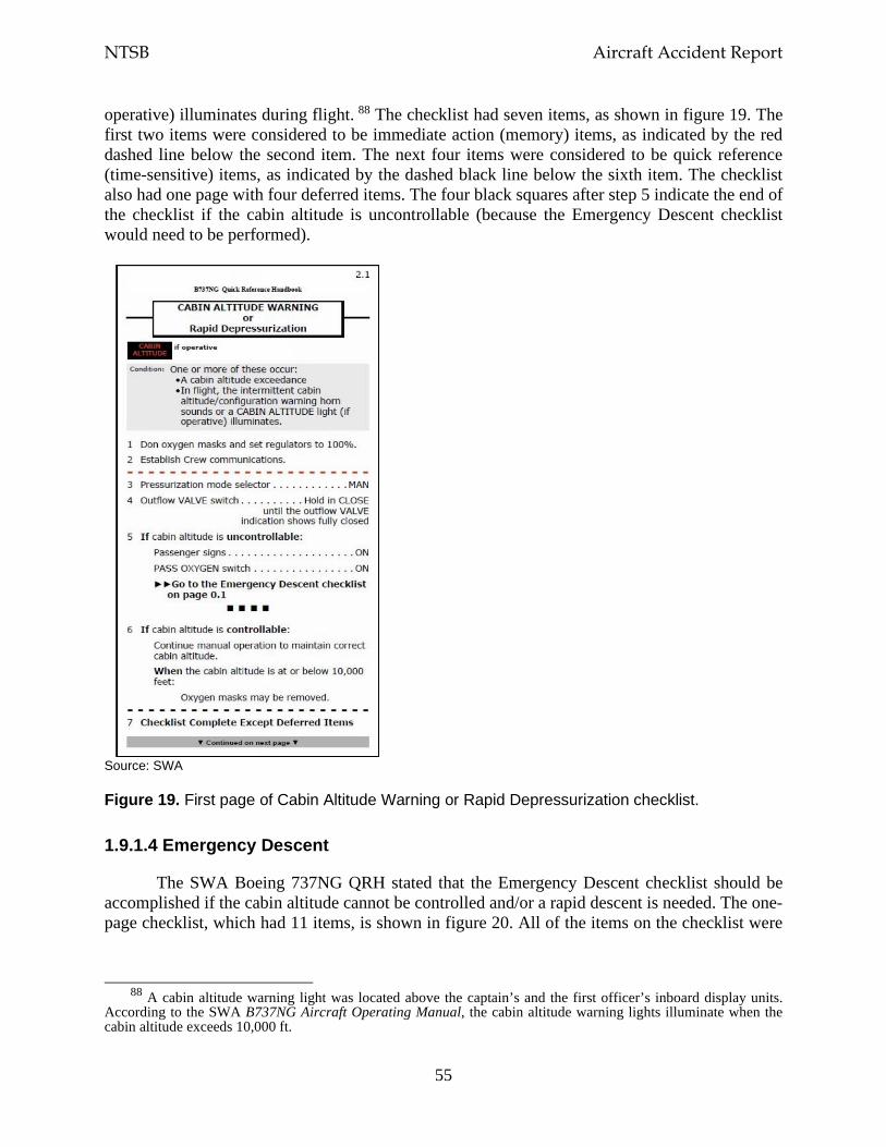
NTSB Aircraft Accident Report
55
operative) illuminates during flight. 88 The checklist had seven items, as shown in figure 19. The first two items were considered to be immediate action (memory) items, as indicated by the red dashed line below the second item. The next four items were considered to be quick reference (time-sensitive) items, as indicated by the dashed black line below the sixth item. The checklist also had one page with four deferred items. The four black squares after step 5 indicate the end of the checklist if the cabin altitude is uncontrollable (because the Emergency Descent checklist would need to be performed).
Source: SWA
Figure 19. First page of Cabin Altitude Warning or Rapid Depressurization checklist.
1.9.1.4 Emergency Descent
The SWA Boeing 737NG QRH stated that the Emergency Descent checklist should be accomplished if the cabin altitude cannot be controlled and/or a rapid descent is needed. The one-page checklist, which had 11 items, is shown in figure 20. All of the items on the checklist were
88 A cabin altitude warning light was located above the captain’s and the first officer’s inboard display units.
According to the SWA B737NG Aircraft Operating Manual, the cabin altitude warning lights illuminate when the cabin altitude exceeds 10,000 ft.
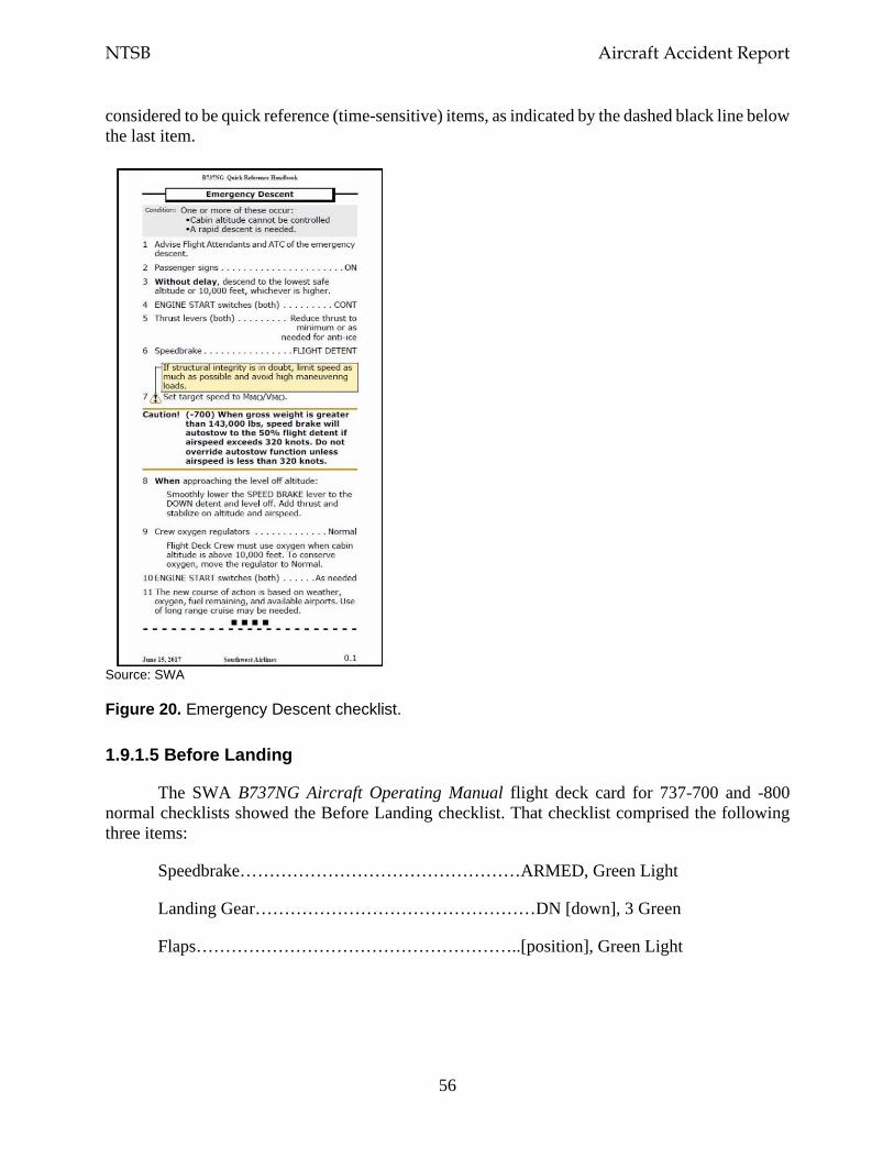
NTSB Aircraft Accident Report
56
considered to be quick reference (time-sensitive) items, as indicated by the dashed black line below the last item.
Source: SWA
Figure 20. Emergency Descent checklist.
1.9.1.5 Before Landing
The SWA B737NG Aircraft Operating Manual flight deck card for 737-700 and -800 normal checklists showed the Before Landing checklist. That checklist comprised the following three items:
Speedbrake…………………………………………ARMED, Green Light
Landing Gear…………………………………………DN [down], 3 Green
Flaps………………………………………………..[position], Green Light
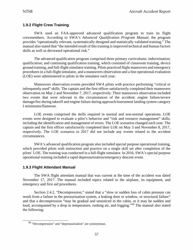
NTSB Aircraft Accident Report
57
1.9.2 Flight Crew Training
SWA used an FAA-approved advanced qualification program to train its flight crewmembers. According to SWA’s Advanced Qualification Program Manual, the program provides “operationally relevant, systematically designed and statistically validated training.” The manual also stated that “the intended result of this training is improved technical and human factors skills as well as decreased operational risk.”
The advanced qualification program comprised three primary curriculums: indoctrination; qualification; and continuing qualification training, which consisted of classroom training, device ground training, and full-flight simulator training. Pilots practiced flight maneuvers and emergency procedures in a full-flight simulator, and a maneuvers observation and a line operational evaluation (LOE) were administered to pilots in the simulator each year.
Maneuvers observation events provided SWA pilots with practice performing “critical or infrequently used” skills. The captain and the first officer satisfactorily completed their maneuvers observation on May 2 and November 7, 2017, respectively. Their maneuvers observation included two events that were relevant to the circumstances of the accident: engine failure/severe damage/fire during takeoff and engine failure during approach/instrument landing system category I minimums/flameout.
LOE events comprised the skills required in normal and non-normal operations. LOE events were designed to evaluate a pilot’s behavior and “risk and resource management” skills, including the identification and management of errors. The LOE scenarios changed each year. The captain and the first officer satisfactorily completed their LOE on May 3 and November 8, 2017, respectively. The LOE scenarios in 2017 did not include any events related to the accident circumstances.
SWA’s advanced qualification program also included special purpose operational training, which provided pilots with instruction and practice on a single skill set after completion of the pilots’ LOE. The training was conducted in a full-flight simulator. In 2016, SWA’s special purpose operational training included a rapid depressurization/emergency descent event.
1.9.3 Flight Attendant Manual
The SWA flight attendant manual that was current at the time of the accident was dated November 17, 2017. The manual included topics related to the airplane, its equipment, and emergency and first aid procedures.
Section 2.4.2, “Decompression,” stated that a “slow or sudden loss of cabin pressure can result from a failure in the pressurization system, a leaking door or window, or structural failure” and that a decompression “may be gradual and unnoticed in the cabin, or it may be sudden and loud, accompanied by a drop in temperature, rushing air, and fogging.”89 The manual also stated the following:
89 “Decompression” and “depressurization” are synonymous.
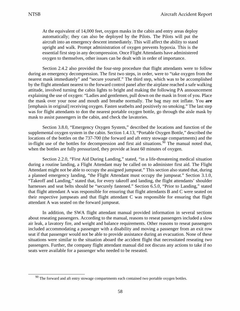
NTSB Aircraft Accident Report
58
At the equivalent of 14,000 feet, oxygen masks in the cabin and entry areas deploy automatically; they can also be deployed by the Pilots. The Pilots will put the aircraft into an emergency descent immediately. This will affect the ability to stand upright and walk. Prompt administration of oxygen prevents hypoxia. This is the essential first step in any decompression. Once Flight Attendants have administered oxygen to themselves, other issues can be dealt with in order of importance.
Section 2.4.2 also provided the four-step procedure that flight attendants were to follow during an emergency decompression. The first two steps, in order, were to “take oxygen from the nearest mask immediately” and “secure yourself.” The third step, which was to be accomplished by the flight attendant nearest to the forward control panel after the airplane reached a safe walking attitude, involved turning the cabin lights to bright and making the following PA announcement explaining the use of oxygen: “Ladies and gentlemen, pull down on the mask in front of you. Place the mask over your nose and mouth and breathe normally. The bag may not inflate. You are [emphasis in original] receiving oxygen. Fasten seatbelts and positively no smoking.” The last step was for flight attendants to don the nearest portable oxygen bottle, go through the aisle mask by mask to assist passengers in the cabin, and check the lavatories.
Section 3.8.0, “Emergency Oxygen System,” described the locations and function of the supplemental oxygen system in the cabin. Section 1.4.13, “Portable Oxygen Bottle,” described the locations of the bottles on the 737-700 (the forward and aft entry stowage compartments) and the in-flight use of the bottles for decompression and first aid situations.90 The manual noted that, when the bottles are fully pressurized, they provide at least 60 minutes of oxygen.
Section 2.2.0, “First Aid During Landing,” stated, “in a life-threatening medical situation during a routine landing, a Flight Attendant may be called on to administer first aid. The Flight Attendant might not be able to occupy the assigned jumpseat.” This section also stated that, during a planned emergency landing, “the Flight Attendant must occupy the jumpseat.” Section 3.1.0, “Takeoff and Landing,” stated that, for every takeoff and landing, the flight attendants’ shoulder harnesses and seat belts should be “securely fastened.” Section 6.5.0, “Prior to Landing,” stated that flight attendant A was responsible for ensuring that flight attendants B and C were seated on their respective jumpseats and that flight attendant C was responsible for ensuring that flight attendant A was seated on the forward jumpseat.
In addition, the SWA flight attendant manual provided information in several sections about reseating passengers. According to the manual, reasons to reseat passengers included a slow air leak, a lavatory fire, and weight and balance requirements. Other reasons to reseat passengers included accommodating a passenger with a disability and moving a passenger from an exit row seat if that passenger would not be able to provide assistance during an evacuation. None of these situations were similar to the situation aboard the accident flight that necessitated reseating two passengers. Further, the company flight attendant manual did not discuss any actions to take if no seats were available for a passenger who needed to be reseated.
90 The forward and aft entry stowage compartments each contained two portable oxygen bottles.
NTSB Aircraft Accident Report
59
1.9.4 Flight Attendant Training
Flight attendants were trained by SWA instructors at Southwest Airlines University. The initial new hire training program was conducted in Dallas. Recurrent training was conducted at each of SWA’s 10 operational bases.
SWA provided its flight attendants, during initial training, with a 68-page guide, titled Inflight Initial Learners Guide, which discussed multiple training topics. The version of the guide that was current at the time of the accident was dated March 1, 2018. The training module on in-flight emergencies included a section that addressed causes of decompression and its effects on airplane occupants. The section also included videos of oxygen mask deployment and operation, information about the portable oxygen bottles and flight deck oxygen, and a news report about an April 2011 decompression event involving a SWA airplane.91
According to in-flight training personnel at Southwest Airlines University, during initial training, flight attendants learn what to tell passengers, over the PA system, if an event requiring oxygen masks were to occur. The flight attendants are also provided with a decompression scenario and given an opportunity to either participate in or observe simulated mask deployments. Further, flight attendants receive instruction on assessing oxygen system operation/flow, manually deploying oxygen masks from the passenger service units, and using the portable oxygen bottles.
The in-flight training personnel stated that flight attendants were instructed to do the following during a decompression event: (1) take oxygen, (2) secure themselves in a jumpseat or passenger seat, (3) turn the cabin interior lights to “full bright,” and (4) make a PA announcement about the decompression and attempt to contact the pilots. These personnel also stated that, once the situation was stable, flight attendants could use a portable oxygen bottle to ensure that passengers were using their masks and check the lavatories for passengers.
The senior manager for in-flight training at Southwest Airlines University indicated the reasons that a flight attendant would not be in a jumpseat during landing. These reasons were (1) a flight attendant was providing first aid (in which case the two other flight attendants would be in their jumpseats); (2) a jumpseat was broken, or there was a hole in the fuselage near the assigned jumpseat (in which case the affected flight attendant would be secured in a passenger seat closest to his/her primary exit; and (3) a flight attendant was incapacitated and thus unable to perform required duties. The senior manager stated that “flight attendants need to be on their jumpseat” during landing because it is “the safest, most secure place for them” and because “they have to potentially be able to evacuate that aircraft.” The senior manager also stated that a passenger should not be reseated on a jumpseat instead of a working flight attendant.
91 The NTSB’s investigation of that accident found that a flight attendant did not follow procedures requiring the
immediate donning of an oxygen mask when cabin pressure was lost (NTSB 2013).

NTSB Aircraft Accident Report
60
1.10 Additional Information
1.10.1 Previous Fan-Blade-Out Accident
On August 27, 2016, SWA flight 3472, a Boeing 737-700 equipped with CFM56-7B engines, N766SW, experienced a left engine failure while climbing through flight level 310 near Pascagoula, Mississippi. The flight crew declared an emergency and diverted to Pensacola International Airport (PNS), Pensacola, Florida, where the airplane made an uneventful single-engine landing. None of the 104 occupants aboard the airplane were injured. The airplane was substantially damaged. The regularly scheduled passenger flight was operating under the provisions of 14 CFR Part 121 from Louis Armstrong New Orleans International Airport, New Orleans, Louisiana, to Orlando International Airport, Orlando, Florida.92 The CVR indicated that the flight crewmembers were using their oxygen masks during part of the emergency descent.
Postaccident examination of the airplane revealed a 16-by-5-inch through-puncture on the left side of the fuselage just below the cabin windows by rows 11 and 12 (with no corresponding damage on the interior cabin sidewall) and numerous impacts along the left side of the fuselage, the left wing, and the left horizontal stabilizer. Also, the left engine inlet was almost completely missing, and the part that remained was severely damaged. In addition, the left winglet front spar was partially severed.
Postaccident examination of the left engine (ESN 874112, which had accumulated 38,152 cycles since new) revealed a full-length fan blade separation (blade No. 23) below the blade platform.93 The blade fractured due to a fatigue crack that initiated in the dovetail on the convex side of the blade near the leading edge, and the maximum crack depth was about 0.695 inch. The estimated striation cycle count was 15,000 cycles.
The fan case did not exhibit any through-hole penetrations, and the containment shield was not breached by the exiting fan blade fragments. The damage to the inlet from the exiting fan blade fragments caused portions of the inlet to separate from the airplane, strike the left-side fuselage, and puncture the outer fuselage skin, which led to a cabin depressurization. None of the separated inlet portions were recovered. The fan cowl remained in place.
The other 23 blades in the fan blade set exhibited airfoil damage but remained intact and secured within the fan disk. Postaccident examination of the fan blade set by the NTSB and CFM found cracks in the dovetails of 6 of the 23 intact fan blades. These cracks could not be seen through the dovetail coating and were discovered after the coating had been removed. As a result, CFM developed an ultrasonic inspection technique that could be performed with the coating still on the dovetail and could thus be used during the on-wing fan blade inspection at the time of relubrication. Table 6 provides information about the cracked fan blades on the SWA flight 3472 accident engine, including fan blade No. 23, which fractured during the flight.
92 For more information, see case number DCA16FA217 at the NTSB’s website (www.ntsb.gov). 93 As of October 31, 2019, the SWA flight 3472 (PNS) and flight 1380 (PHL) accidents were the only known
CFM56-7B full-length fan blade release events.
NTSB Aircraft Accident Report
61
Table 6. Fan blade cracks on SWA flight 3472 accident engine.
Blade number Maximum fatigue crack depth (inch)
Number of estimated cycles of crack growth
1 0.009 4,000 2 0.015 4,000 11 0.060 10,000 17 0.023 5,000 19 0.019 4,000 23 0.695 15,000 24 0.126 16,000
Also, as a result of the SWA flight 3472 accident, CFM developed an ECI procedure for the dovetail to be performed at overhaul (in addition to the FPI that was already required). The ECI involves a manual scan of both the concave and convex sides of the dovetail with the blade coating removed.94 In November 2016, this requirement was added to CFM’s engine shop manual.
1.10.2 Service Bulletins and Airworthiness Directives
This section discusses, and table 7 summarizes, the CFM SBs and the FAA and EASA airworthiness directives (AD) that were issued after the August 27, 2016, SWA flight 3472 accident (see previous section) and the April 17, 2018, SWA flight 1380 accident. This section also includes pertinent information regarding actions taken as a result of the SBs and ADs.
Table 7. CFM, FAA, and EASA documents regarding CFM56-7B fan blade dovetail inspections.
Issue date Document Subject Report section 03/24/17 CFM SB 72-1019 One-time ultrasonic inspection of all fan blades
installed in engines with more than 15,000, 12,000, or 9,000 flight cycles since the last shop visit within 6, 12, and 18 months, respectively
1.10.2.1
06/20/17 CFM SB 72-1019 revision 1
One-time ultrasonic inspection of all fan blades installed in engines with more than 15,000 flight cycles since the last shop visit within 6 months
1.10.2.1
07/28/17 CFM SB 72-1024 One-time ultrasonic inspection of fan blades that were modified from a specific part number as soon as possible but no later than 12/31/18 regardless of an engine’s total number of flight cycles or cycles since the last shop visit
1.10.2.2
08/25/17 FAA notice of proposed rulemaking
One-time ultrasonic inspection of all fan blades on engines with more than 15,000 cycles since the last shop visit as well as 15,000 or fewer cycles since new (based on SB 72-1019)
1.10.2.1
03/26/18 EASA AD 2018-0071 One-time ultrasonic inspection of engines with fan blades that had specific part numbers within 9 months (based on SB 72-1024)
1.10.2.7
04/20/18 CFM SB 72-1033 Initial and repetitive ultrasonic inspections for all engine fan blades based on an engine’s cycles
1.10.2.3
94 The fan blade ultrasonic inspection and ECI both involve a manual scan of the concave and convex sides of
the dovetail, but the orientation of the ultrasonic inspection scan is slightly different than an ECI scan. Specifically, the ultrasonic inspection is performed using a probe to scan along the root end face of the fan blade, where the blade coating does not interfere with the scan, whereas the ECI is performed using a probe to scan directly on the dovetail surface under the coating where cracks can initiate, so the blade coating needs to be removed.
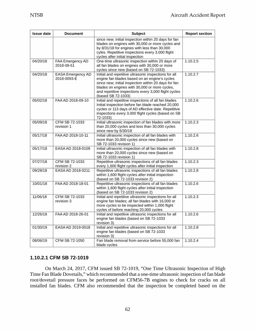
NTSB Aircraft Accident Report
62
Issue date Document Subject Report section since new; initial inspection within 20 days for fan blades on engines with 30,000 or more cycles and by 8/31/18 for engines with less than 30,000 cyles. Repetitive inspections every 3,000 flight cycles after initial inspection
04/20/18 FAA Emergency AD 2018-09-51
One-time ultrasonic inspection within 20 days of all fan blades on engines with 30,000 or more cycles since new (based on SB 72-1033)
1.10.2.5
04/20/18 EASA Emergency AD 2018-0093-E
Initial and repetitive ultrasonic inspections for all engine fan blades based on an engine’s cycles since new; initial inspection within 20 days for fan blades on engines with 30,000 or more cycles, and repetitive inspections every 3,000 flight cycles (based SB 72-1033)
1.10.2.7
05/02/18 FAA AD 2018-09-10 Initial and repetitive inspections of all fan blades. Initial inspection before fan blade reached 20,000 cycles or 113 days of AD effective date. Repetitive inspections every 3,000 flight cycles (based on SB 72-1033)
1.10.2.6
05/09/18 CFM SB 72-1033 revision 1
Initial ultrasonic inspection of fan blades with more than 20,000 cycles and less than 30,000 cycles since new by 6/30/18
1.10.2.3
05/17/18 FAA AD 2018-10-11 Initial ultrasonic inspection of all fan blades with more than 20,000 cycles since new (based on SB 72-1033 revision 1)
1.10.2.6
05/17/18 EASA AD 2018-0109 Initial ultrasonic inspection of all fan blades with more than 20,000 cycles since new (based on SB 72-1033 revision 1)
1.10.2.8
07/27/18 CFM SB 72-1033 revision 2
Repetitive ultrasonic inspections of all fan blades every 1,600 flight cycles after initial inspection
1.10.2.3
09/28/18 EASA AD 2018-0211 Repetitive ultrasonic inspections of all fan blades within 1,600 flight cycles after initial inspection (based on SB 72-1033 revision 2)
1.10.2.8
10/01/18 FAA AD 2018-18-01 Repetitive ultrasonic inspections of all fan blades within 1,600 flight cycles after initial inspection (based on SB 72-1033 revision 2)
1.10.2.6
11/06/18 CFM SB 72-1033 revision 3
Initial and repetitive ultrasonic inspections for all engine fan blades; all fan blades with 16,000 or more cycles to be inspected within 1,000 flight cycles of before reaching 20,000 cycles
1.10.2.3
12/26/18 FAA AD 2018-26-01 Initial and repetitive ultrasonic inspections for all engine fan blades (based on SB 72-1033 revision 3)
1.10.2.6
01/30/19 EASA AD 2019-0018 Initial and repetitive ultrasonic inspections for all engine fan blades (based on SB 72-1033 revision 3)
1.10.2.8
08/06/19 CFM SB 72-1050 Fan blade removal from service before 55,000 fan blade cycles
1.10.2.4
1.10.2.1 CFM SB 72-1019
On March 24, 2017, CFM issued SB 72-1019, “One Time Ultrasonic Inspection of High Time Fan Blade Dovetails,” which recommended that a one-time ultrasonic inspection of fan blade root/dovetail pressure faces be performed on CFM56-7B engines to check for cracks on all installed fan blades. CFM also recommended that the inspection be completed based on the
NTSB Aircraft Accident Report
63
engine’s cycles since the last shop visit.95 The SB indicated that, for engines with more than 15,000, 12,000, or 9,000 flight cycles since the last shop visit, the actions in the SB should be performed within 6, 12, or 18 months, respectively, of the date that the SB was issued. CFM defined this SB as “category 2,” which CFM uses when “technical reasons make the compliance necessary.” 96
On June 20, 2017, CFM issued revision 1 to SB 72-1019, which removed two of the recommended compliance intervals (for engines with 12,000 or 9,000 cycles since the last shop visit). Thus, the SB maintained the compliance interval (6 months) only for engines with more than 15,000 cycles since the last shop visit because the number of cycles before the recommended inspection was determined to be adequate. According to SWA, SB 72-1019 applied to 111 of the company’s engines; the left engine installed on the PHL accident airplane was not among those engines because it was below the 15,000-cycle threshold for inspection, with 8,483 cycles since the last shop visit at the time that the SB was issued.97
On August 25, 2017, the FAA issued a notice of proposed rulemaking (NPRM) to adopt a new AD for certain CFM56-7B turbofan engines (FAA 2017). The NPRM was based on the information in CFM SB 72-1019 revision 1. According to the NPRM, the proposed AD would correct an unsafe condition by requiring an ultrasonic inspection of fan blades and the replacement of blades that failed the inspection. The proposed AD would have required CFM56-7B engines with more than 15,000 cycles since the last shop visit to be inspected within 6 months of the effective date of the AD. The proposed AD would have also required CFM56-7B engines with 15,000 or fewer cycles in service to be inspected within 18 months after the effective date of the AD or at the next fan blade relubrication after the effective date of the AD, whichever occurred first. Thus, the AD would have applied to the accident engine.
The comment period for the NPRM closed on October 10, 2017. During the investigative hearing for this accident, the FAA stated that it was responding to public comments on the NPRM and developing the final rule at the time of the accident. The FAA withdrew the NPRM in September 2018 but issued an emergency AD as well as immediate adopted rules between the time of the accident and the withdrawal of the NPRM, as discussed in this section.98
95 Because CFM did not certify the fan blade as a life-limited part, there was no requirement to track fan blade
times and cycles; thus, the SB considered the number of engine cycles. In May 2015, SWA began tracking the fan blade times and cycles for blades entering service.
96 CFM indicated that category 2 SBs “may cause non-routine customer action.” Unless otherwise noted, the SBs and SB revisions described in this section are category 2.
97 SWA reported that all but 4 of the 111 engines were inspected before mid-September 2017. SWA had extended the completion date for the four engines either because of the impact of a hurricane on the HOU maintenance base or because the engines were already undergoing heavy maintenance. The inspections of those engines were completed on or before October 12, 2017.
98 According to the FAA, an emergency AD addresses high-risk safety issues, has a very short compliance time, and is effective upon receipt. An immediate adopted rule addresses medium-risk safety issues and has a compliance time that is not long enough to allow public comment through the NPRM process, but the FAA seeks public comments after the effective date of the AD. A final rule addresses unsafe conditions and has a compliance time that allows for public comment through the NPRM process.
NTSB Aircraft Accident Report
64
1.10.2.2 CFM SB 72-1024
On July 28, 2017, CFM issued SB 72-1024, “Ultrasonic Inspection of Fan Blade Dovetails.” This SB applied to fan blades on CFM56-7B engines that were modified from part number -022 (including -027, which was the part number of the blades installed in the SWA flight 3472 airplane engine). SB 72-1024 recommended that the ultrasonic inspections be performed as soon as possible but no later than December 31, 2018, regardless of an engine’s total number of flight cycles or cycles since the last shop visit. The part number for the fan blades installed in the accident engine (-038) was not included in the SB; thus, the SB did not apply to the accident engine.
1.10.2.3 CFM SB 72-1033
On April 20, 2018 (3 days after the SWA flight 1380 accident), CFM issued SB 72-1033, “Fan Blade Dovetail Repetitive Ultrasonic Inspection,” to address “a condition that may affect flight safety.” The SB recommended initial and repetitive ultrasonic inspections for all CFM56-7B engine fan blades based on an engine’s cycles since new (and not the engine’s cycles since the last shop visit, as with SB 72-1019). This SB established the following initial inspection procedures:
• For engines with 30,000 or more cycles since new, perform the initial fan blade dovetail ultrasonic inspection within 20 days (May 10, 2018) of the SB date.
• For engines with less than 30,000 cycles since new, if the fan blade cycles since new are known, perform the initial ultrasonic inspection no later than 20,000 fan blade cycles since new or August 31, 2018, whichever occurred later. If the fan blade cycles since new are unknown, perform the initial ultrasonic inspection no later than August 31, 2018.
SB 72-1033 called for repetitive ultrasonic inspections every 3,000 flight cycles, which corresponded with the upper limit of the fan blade relubrication interval at the time. The SB also addressed fan blades that were not installed on an engine, recommending that those fan blades be inspected before engine installation except if the fan blades had fewer than 20,000 cycles since new or had been inspected according to the SB within the previous 300 flight cycles.
On May 9, 2018, CFM issued revision 1 to SB 72-1033, which moved the completion date forward, from August 31 to June 30, 2018, for the ultrasonic inspections of CFM56-7B fan blades with more than 20,000 cycles since new. The SB indicated that the fan blades with the highest number of cycles should receive priority. Revision 1 did not change any other inspection provision recommended in the initial SB, but CFM defined the revised SB as “category 1,” meaning that “compliance is mandatory, generally as a result of the DGAC or FAA action…. Will cause customer action.”
On July 27, 2018, CFM issued revision 2 (category 1) to SB 72-1033, which reduced the interval for repetitive inspections from within 3,000 to 1,600 flight cycles. This change was based
NTSB Aircraft Accident Report
65
on the results from the cracked fan blade inspections and CFM’s revised crack propagation analysis, which reflected the findings from the inspections.99
On November 6, 2018, CFM issued revision 3 (category 1) to SB 72-1033 to update the fan blade dovetail inspection procedures as follows:
• For fan blades with more than 16,000 cycles since new, perform the initial dovetail ultrasonic inspection within 1,000 flight cycles or before 20,000 cycles since new. For all other fan blades, perform the inspection before 17,000 cycles since new.
• For replacement fan blades with more than 17,000 cycles since new, complete the initial dovetail ultrasonic inspection. If a fan blade’s cycles since new are unknown, complete the inspection by November 30, 2018.
• Repeat the dovetail ultrasonic inspection every 1,600 flight cycles after the initial inspection. For fan blades with more than 1,600 flight cycles since the initial inspection, repeat the inspection by November 30, 2018. If the initial dovetail ultrasonic inspection was completed before the fan blades accumulated 15,400 cycles since new, the first repetitive inspection could be deferred until the fan blades accumulated 17,000 cycles since new.
1.10.2.4 CFM SB 72-1050
On August 6, 2019, CFM issued SB 72-1050 to provide a recommended removal time for CFM56-7B fan blades. Although the fan blades were not certified as a life-limited part, the SB recommended that high-time fan blades be removed from service because they are susceptible to dovetail cracks. Specifically, CFM recommended that fan blades be removed from service before 55,000 fan blade cycles since new or June 30, 2020, whichever occurs later. For fan blades that have accumulated 55,000 or more fan blade cycles since new, CFM recommended that the fan blades be removed from service not later than the next fan blade dovetail lubrication.100
1.10.2.5 FAA Emergency AD 2018-09-51
On April 20, 2018 (the same day that CFM SB 72-1033 was initially issued), the FAA issued emergency AD 2018-09-51 as a result of the fan blade separation and subsequent inlet and fan cowl departure involving SWA flight 1380; the FAA determined that this unsafe condition was “likely to exist or develop” in other CFM56-7B engines (FAA 2018a). The emergency AD targeted CFM56-7B engines with 30,000 or more cycles since new. The emergency AD required that, within 20 days (May 10, 2018) of the AD’s issuance, all CFM56-7B fan blades undergo an
99 CFM found a relatively stable crack propagation rate in the cracked fan blade dovetails. Given the ultrasonic
inspection crack depth detection threshold of 0.06 inch, CFM wanted to ensure that at least two ultrasonic inspections would be performed with the crack depth greater than the detection threshold but less than the critical size at which the fan blade could separate. Thus, if an ultrasonic inspection was performed with the crack below the detectable threshold, a subsequent ultrasonic inspection should detect the crack before a fan blade separation could occur. CFM indicated that the recommended repetitive inspection interval should provide, on average, about six separate opportunities to detect a dovetail crack before it would reach a critical size.
100 CFM SB 72-1050 also included a method for determining the number of fan blade cycles since new for fan blades with an unknown number of cycles since new.
NTSB Aircraft Accident Report
66
ultrasonic inspection for cracks (according to the instructions provided in CFM SB 72-1033). The emergency AD also required that any fan blade with indications of a crack be removed from service before further flight because “fan blade failure due to cracking, if not addressed, could result in an engine in-flight shutdown…uncontained release of debris, damage to the engine, damage to the airplane, and possible airplane decompression.”
When FAA emergency AD 2018-09-51 was issued, SWA had 279 CFM56-7B engines with 30,000 or more cycles since new. These engines were installed on airplanes or were spares available for installation. By April 25, 2018, all 279 engines had received the ultrasonic inspection required by the emergency AD. A crack was discovered on a fan blade installed in one of these engines (see table 4).
1.10.2.6 FAA ADs 2018-09-10, 2018-10-11, 2018-18-01, and 2018-26-01
On May 2, 2018, the FAA issued AD 2018-09-10, which mandated initial and repetitive inspections (ultrasonic or ECI) of all CFM56-7B fan blades, including those installed on engines with less than 30,000 cycles (FAA 2018b).101 (Emergency AD 2018-09-51 did not require repetitive inspections or include engines with fewer than 30,000 cycles.) The AD, which had an effective date of May 14, 2018, required an initial inspection before the fan blades accumulated 20,000 cycles since new or within 113 days (September 4, 2018) of the effective date of the AD, whichever was later.102 The AD also required repetitive ultrasonic inspections every 3,000 flight cycles.
On May 17, 2018, the FAA superseded AD 2018-09-10 with AD 2018-10-11, which revised the compliance time for those CFM56-7B fan blades with more than 20,000 cycles since new because of their higher risk for cracks (FAA 2018c). The AD, which had an effective date of June 1, 2018, required that these fan blades undergo inspections (ultrasonic or ECI) within 30 days (July 1, 2018) of the effective date of the AD; all other fan blades were required to be inspected within 90 days (August 30, 2018) from the effective date of the AD or before accumulating 20,000 flight cycles. The AD maintained the repetitive ultrasonic inspection requirement of every 3,000 flight cycles.
According to SWA, as of May 18, 2018, all of the company’s CFM56-7B fan blades with more than 3,000 cycles since new had been inspected using either ultrasonic inspections or ECIs. In June 2018, a crack on a SWA engine blade was found by an ECI of the dovetail during overhaul (see table 4).
On October 1, 2018, the FAA superseded AD 2018-10-11 with AD 2018-18-01, which required the same initial inspection as the superseded AD but revised the compliance interval for the repetitive inspection (FAA 2018d). The new AD required that a repetitive ultrasonic inspection or ECI of the concave and convex sides of the fan blade dovetail occur no later than 1,600 flight
101 The issue dates for the FAA ADs discussed in this section reflect the dates that the ADs appeared in the
Federal Register. 102 If the fan blade cycles since new were not known, the initial inspection was required to be performed within
113 days of the effective date of the AD.
NTSB Aircraft Accident Report
67
cycles since the last inspection or within 450 cycles after October 16, 2018, the effective date of this AD, whichever occurred later.
On December 26, 2018, the FAA superseded AD 2018-18-01 with AD 2018-26-01, which required the same initial and repetitive inspections as in the superseded AD but reduced the compliance time for the initial inspection from 20,000 to 17,000 cycles since new (FAA 2018e). Specifically, for fan blades with 16,000 or fewer cycles since new, the initial ultrasonic inspection was required to be performed before 17,000 cycles since new. For fan blades with more than 16,000 but less than 20,000 cycles since new, the inspection was required to be performed within 1,000 cycles but no later than 20,000 cycles since new. For fan blades with 20,000 or more cycles since new, the inspection was required to be performed before further flight. The AD had an effective date of January 10, 2019.
In an August 21, 2019, memorandum to the NTSB, the FAA stated that it was not considering any additional proposed rulemaking for CFM56-7B fan blades. On October 23, 2019, the FAA indicated that it was planning to issue a Special Airworthiness Information Bulletin that discusses the recommendation in CFM SB 72-1050 (see section 1.10.2.4) to remove CFM56-7B fan blades from service before they accumulate 55,000 fan blade cycles.
1.10.2.7 EASA Emergency AD 2018-0093-E
On April 20, 2018 (the same day that CFM SB 72-1033 and FAA emergency AD 2018-09-51 were issued), EASA issued emergency AD 2018-0093-E.103 The emergency AD required an initial ultrasonic inspection of all CFM56-7B engine fan blades (EASA 2018b). Similar to the requirements of the FAA’s emergency AD, EASA’s emergency AD required compliance within 20 days (May 10, 2018) of the AD’s issue date for engines with 30,000 or more flight cycles. The AD stated that, for engines with fewer than 30,000 flight cycles and fan blades with either 20,000 or more cycles or unknown times, the required action had to be completed by August 31, 2018. For engines with fewer than 30,000 flight cycles and fan blades with fewer than 20,000 cycles, the required action had to be completed either by August 31 or before the fan blades reached 20,000 cycles, whichever occurred later. The AD also required repetitive ultrasonic inspections within 3,000 flight cycles. Fan blades with discrepancies were required to be replaced before the next flight or before the engine’s return to service.
1.10.2.8 EASA ADs 2018-0109, 2018-0211, and 2019-0018
On May 17, 2018, EASA superseded emergency AD 2018-0093-E with AD 2018-0109, which became effective the next day. The new AD reduced the compliance time for the initial ultrasonic inspection of CFM56-7B engine fan blades that had more than 20,000 cycles since new (EASA 2018c). For fan blades with 20,000 or more cycles since new, and for fan blades with an unknown number of cycles installed on engines with 20,000 to 30,000 cycles since new, the initial
103 This emergency AD superseded EASA AD 2018-0071, which was issued on March 26, 2018. AD 2018-0071
required a one-time ultrasonic inspection of CFM56-7B engines with fan blades that had specific part numbers; the accident blade part number was not mentioned in the AD (EASA 2018a). The inspection was required to be performed within 9 months from the April 2, 2018, effective date of the AD. If any discrepancy was found during the ultrasonic inspection, the fan blade was required to be replaced before the next flight or the engine’s return to service.
NTSB Aircraft Accident Report
68
inspection was required within 43 days (July 30, 2018) of the effective date of the AD. For fan blades with an unknown number of cycles installed on engines with less than 20,000 flight cycles, the initial inspection was required within 133 days (August 11, 2018) of the date of EASA emergency AD 2018-0093-E (April 20, 2018).
On September 28, 2018, EASA superseded AD 2018-0109 with AD 2018-0211, which reduced the interval for the repetitive ultrasonic inspections from 3,000 to 1,600 flight cycles (EASA 2018d). The AD allowed operators of CFM56-7B engines with fan blades that had passed an ultrasonic inspection as of October 5, 2018, the effective date of the AD, to defer the next inspection until 2 months after the effective date of the AD as long as 3,000 flight cycles had not elapsed since the time of the last blade inspection.
On January 30, 2019, EASA superseded AD 2018-0211 with AD 2019-0018, which reduced the threshold for the initial ultrasonic inspection (EASA 2019). For fan blades with 16,000 or fewer cycles since new, the initial ultrasonic inspection was required to be performed before 17,000 cycles since new. For fan blades with more than 16,000 but less than 20,000 cycles since new, the inspection was required to be performed within 1,000 flight cycles after February 13, 2019 (the effective date of the AD), and without exceeding 20,000 cycles since new. For fan blades with 20,000 or more cycles since new and fan blades with an unknown number of cycles, the inspection was required to be performed before the next flight after the effective date of the AD.
1.10.3 CFM56-7B Fan Blade Inspections
According to CFM, when FAA Emergency AD 2018-09-51 and EASA Emergency AD 2018-0093-E were issued, about 640 engines worldwide had accumulated 30,000 cycles since new (the inspection criteria). By May 10, 2018 (the compliance date for the ADs), all 640 engines had been inspected. CFM considered the inspection required by the emergency ADs to be the first of three inspection campaigns.
CFM considered those engines addressed by revision 1 to SB 72-1033 to be part of the second inspection campaign. CFM estimated that about 5,400 engines had fan blades with more than 20,000 cycles (the inspection criteria). The SB compliance date was June 30, 2018.
CFM’s third (and final) campaign was to inspect the fan blades on all other engines by August 31, 2018 (the compliance date for SB 72-1033 for engines with fan blades not subject to revision 1 of the SB). CFM estimated that about 4,250 engines met that criteria.
In addition, CFM estimated that about 356,000 CFM56-7B fan blades and 14,659 CFM56-7B engines had been delivered as of August 22, 2018. According to CFM, by that date, all CFM56-7B fan blades targeted by FAA AD 2018-10-11 and EASA AD 2018-0109 had either an on-wing ultrasonic inspection or an ECI during a shop visit or were cleared through paperwork indicating that the fan blades had fewer than 20,000 cycles.
As of June 2018, 15 cracked CFM56-7B fan blades had been confirmed. Two of these cracked blades were confirmed during postaccident examinations of the fractured blades associated with the SWA flight 3472 (PNS) and flight 1380 (PHL) FBO events. Six of the cracked blades were also installed on the SWA flight 3472 engine (see table 6) and were discovered during
NTSB Aircraft Accident Report
69
postaccident inspections (FPI, ECI, or ultrasonic) of the blades. Of the remaining seven cracked blades, three were found during the time between the SWA flight 3472 and flight 1380 accidents, and four were found in the 2 months after the SWA flight 1380 accident (see table 4).104 The cracks on these seven blades were detected by either ultrasonic inspection during on-wing inspections with the dovetail coating still present or ECI during overhaul with the dovetail coating removed.105
Examination of the 15 cracked fan blades revealed no material anomalies. All of the cracks were located in the highest (maximum) low-cycle fatigue predicted stress areas—the leading edge on the convex side of the fan blade dovetail and the trailing edge of the concave side of the blade dovetail).106 For 14 of the 15 fan blades, the estimated cumulative striation cycle count ranged from 4,000 to 20,000 cycles, which resulted in an average cycle count of about 9,500 cycles. (Data were insufficient to estimate the striation cycle count for one fan blade.)
CFM reevaluated the fan blade dovetail stresses and found that the fatigue cracks initiated in an area of high stress on the dovetail and that the dovetail was experiencing peak stresses that were higher than originally predicted. CFM also found that the higher operational stresses resulted from coating spalling, higher friction levels when operated without lubrication or a shim, variations in coating thickness, higher dovetail edge loading (at the dovetail contact surface and fan disk interface) than predicted, and a loss or relaxation of compressive residual stress. As a result, in July 2018, CFM decreased the interval between relubrications from within 3,000 to 1,600 cycles to reduce the overall stresses on the fan blade dovetail.
Between August and December 2018, four additional cracked fan blades on CFM56-7B engines were identified during ECIs; three of those blades were installed on different SWA engines. The four fan blades had accumulated between about 21,000 and 36,000 cycles since new when the cracks were detected. For three of the four blades, the estimated cumulative striation cycle count ranged from 2,300 to 8,200 cycles, which resulted in an average cycle count of about 5,000 cycles. (The estimated striation cycle count for one blade was not determined.) The three cracks had a depth of 0.014 (concave side), 0.009 (convex side), and 0.026 inch (convex side).
Through August 2019, another four cracked fan blades on CFM56-7B engines were identified during ECIs. The fan blades, which were installed on different SWA engines, had accumulated between 37,000 and 43,000 cycles since new. One fan blade had cracks on both the concave and convex sides, two fan blades had a crack on the convex side, and one fan blade had a crack on the concave side.
104 The maximum crack depths for the three cracked blades found between the SWA flight 3472 and flight 1380
accidents were 0.061, 0.016, and 0.017 inch. For the first two of these three cracked blades, the estimated cycles of crack growth were 9,000 and 7,500 cycles, respectively. The available data for the third blade were insufficient to estimate the number of cycles of crack growth.
105 The fan blade cracks detected by ultrasonic inspection were confirmed using ECI. 106 The cracks were located on the convex side of the fan blade for all but 1 of the 15 blades.
NTSB Aircraft Accident Report
70
2. Analysis 2.1 Introduction
This accident occurred after fan blade No. 13 in the left engine fractured at its root, with the dovetail (part of the blade root) remaining within a slot of the fan disk. The separated fan blade impacted the engine fan case and fractured into multiple fragments. Some of those fragments traveled forward into the inlet, causing substantial damage to the inlet structure. The energy from the impact of the separated fan blade with the fan case resulted in local deformation of the fan case, which started a high-energy displacement wave that propagated circumferentially and caused additional damage to the inlet structure. The fan blade’s impact with the fan case also caused substantial damage to the fan cowl structure, including fractures that initiated and rapidly propagated within the fan cowl. As a result, portions of the inlet and fan cowl departed the airplane. A fan cowl fragment contacted the fuselage, causing a cabin window to depart the airplane, a rapid depressurization, and a passenger fatality. The flight crew conducted an emergency descent and made a safe single-engine landing at PHL.
The following analysis summarizes the accident (section 2.2) and evaluates the following:
• CFM’s certification of the engine and Boeing’s certification of the inlet and fan cowl (section 2.3),
• the flight crew’s checklist performance and emergency landing airport selection (section 2.4), and
• occupant safety during emergency landings (section 2.5).
After completing a comprehensive review of the circumstances that led to this accident, the investigation established that the following factors did not contribute to the cause of the accident:
Flight crew qualifications. The flight crew was properly certificated and qualified in accordance with SWA requirements and 14 CFR Part 121.
Flight crew medical conditions. The flight crew held valid and current medical certificates. A review of the flight crew’s work and sleep schedules and recent activities showed no evidence of factors that could have adversely affected the performance of either crewmember on the day of the accident.
Airplane mechanical conditions. The airplane was properly certificated, equipped, and maintained in accordance with 14 CFR Part 121. No evidence indicated any structural, engine, or system failures before the left engine failure occurred.
Thus, the NTSB concludes that none of the following were factors in this accident: (1) flight crew qualifications, which were in accordance with US regulations; (2) flight crew medical conditions; (3) the airworthiness of the airplane before the left engine failure occurred; and (4) SWA’s maintenance of the airplane.
NTSB Aircraft Accident Report
71
In addition, the CVR transcript indicated that, after landing, the captain intended to pull the CVR circuit breaker, but she had most likely pulled the three circuit breakers for the FDR given her comment, “I just pulled all three.” As a result, the CVR continued to record. However, because the CVR records data in a continuous loop, valuable investigative information could have been lost. Although that was not the case for this investigation, the NTSB notes that it is important for flight crews involved in an accident or incident to properly perform the procedure to deactivate the CVR.
2.2 Accident Summary
2.2.1 Fan Blade Release
Fan blade No. 13 in the left engine separated due to a low-cycle fatigue crack that initiated in the blade root dovetail outboard of the blade coating. Metallurgical examination of the fan blade found that its material composition and microstructure were consistent with the specified titanium alloy and that no surface anomalies or material defects were observed in the fracture origin area. The fracture surface had fatigue cracks that initiated close to where the greatest stresses from operational loads, and thus the greatest potential for cracking, were predicted to occur.
The accident fan blade failed with 32,636 cycles since new. Similarly, the fractured fan blade associated with the August 2016 PNS accident (see section 1.10.1), as well as the six other cracked fan blades from the PNS accident engine, failed with 38,152 cycles since new. Further, 15 other cracked fan blades on CFM56-7B engines had been identified between May 2017 and August 2019, and those fan blades had accumulated an average of about 33,000 cycles since new when the cracks were detected.107
After the PNS accident, CFM reevaluated the fan blade dovetail stresses and determined that the cracks in the fan blade dovetail initiated in an area of high stress on the blade because normal operational stresses on the dovetail were higher than the peak stresses that were originally predicted. Before the application of the dovetail coating during manufacturing and before the reapplication of the coating that is stripped during each overhaul, the entire blade, including the dovetail, is shot-peened to provide a compressive residual stress surface layer for the material, which increases the fatigue strength of the material and relieves surface tensile stresses that can lead to cracking. However, higher-than-expected dovetail operational stresses can lead to the loss/relaxation of residual stress (the stress that is present in solid material in the absence of external forces) and premature fatigue crack initiation.108
As part of the PHL investigation, five intact fan blades from the accident fan disk were examined to determine their residual stress condition. The results of the residual stress
107 Three of the 21 cracked fan blades were identified between the time of the PNS and PHL accidents, and
12 were identified after PHL accident through August 2019. 108 A loss of residual stress could also be the result of a fan blade’s exposure to high temperatures during the
application of the dovetail coating as part of the overhaul of a blade set, but no evidence indicated that the accident fan blade dovetail was subjected to an overheat situation during overhaul.
NTSB Aircraft Accident Report
72
measurements showed abnormal residual stress profiles, including relaxed peak compressive stresses (most with residual tension near the surface), in one or more locations on each of the fan blade dovetails in the shot-peened area.109 Abnormal residual stress profiles were also measured on fan blade dovetails from the PNS accident engine and on two cracked blades (found during subsequent inspections) that had not been shot-peened (as part of overhaul) since the time that the cracks were estimated to have initiated.
One method that CFM used to maintain the fan blade loads within the predicted range and reduce the overall stresses on the blade root in the contact areas was repetitive relubrication of the fan blade dovetails. As part of the relubrication, the fan blades were visually inspected for crack indications. Between November 29, 2012 (the date that the left engine was installed on the PHL accident airplane), and April 17, 2018 (the date of the PHL accident), the dovetails on the accident fan blade set were relubricated seven times; thus, there would have been seven visual inspections of the fan blades. However, no cracks were found, even though the crack on fan blade No. 13 had likely existed since October 2012 (the date of the last fan blade overhaul).110 Given the surface finish and compressive surface residual stress state of the fan blades, the size of the crack on the accident fan blade was likely below the visual inspection detection threshold.
The crack was located outboard of the fan blade dovetail coating. However, during the investigation of the PNS accident, the NTSB observed fan blade cracks that had initiated and propagated underneath the dovetail coating. Because such cracks might not be detected during a visual inspection, CFM implemented, in March 2017, an on-wing ultrasonic inspection method (developed in November 2016) to detect cracks with the coating still on the dovetail. After completion of the ultrasonic inspection, the fan blade dovetails are relubricated before being reinstalled in the fan disk.
After the PNS accident, CFM issued SBs that addressed the ultrasonic inspections of high-cycle CFM56-7B fan blades.111 One of these SBs, revision 1 of SB 72-1019 (issued on June 20, 2017), called for a one-time ultrasonic inspection of all CFM56-7B engines with more than 15,000 cycles since the last shop visit; this inspection was to be performed within 6 months of the SB issue date. The SB applied to 111 of SWA’s engines, but the left engine installed on the PHL accident airplane was not one of them because the engine had accumulated 8,483 cycles since the last shop visit and thus was below the inspection threshold. Another related SB, 72-1024 (issued on July 28, 2017), called for a one-time ultrasonic inspection of CFM56-7B engines with fan blades that had specific part numbers; the part number for the fan blades installed on the accident
109 The residual stress measurements on blade No. 13 (taken in two locations) showed a normal stress profile.
However, after the crack had initiated, the blade had been shot-peened during overhaul, which reset the residual stress state and removed any evidence of the relaxed residual stresses associated with crack initiation.
110 Striation density measurements were made in the region of the fatigue crack growth to estimate the number of stress cycles from crack initiation to failure; one striation correlated with one engine flight cycle. The results of these measurements were then used, along with the number of cycles since the fan blade set’s last relubrication, to estimate the number of flight cycles that elapsed between crack initiation and fracture. The estimated total number of striations/flight cycles from crack growth to fan blade failure was about 20,000 cycles. At the time of the accident, the engine had accumulated 40,569 cycles, including 10,712 cycles between the time of the overhaul and the accident.
111 After the PHL accident, CFM issued additional SBs on this subject (see section 1.10.2).
NTSB Aircraft Accident Report
73
engine was not included in the SB. As a result, an ultrasonic inspection of the fan blades on the accident engine was not required to be performed.
In addition, at the time of the PHL accident, the fan blades had accumulated 10,712 cycles since their last overhaul in October 2012. As part of that overhaul, an FPI was performed (as specified in the engine maintenance manual) to detect cracks, but the crack in fan blade No. 13 was not detected. The NTSB could not determine why the crack was not detected; it is possible that the size of the crack might have been below the FPI detection threshold. After the PNS accident, CFM implemented, in November 2016, an ECI technique for the fan blade dovetail as part of the overhaul process. An ECI has a higher sensitivity than an FPI and can detect cracks at or near the surface (unlike an FPI, which can only detect surface cracks).
The NTSB concludes that the low-cycle fatigue crack in the fan blade dovetail initiated because of higher-than-expected dovetail stresses under normal operating loads, and this crack was most likely not detectable during the FPI at the time of the fan blade set’s last overhaul and subsequent visual inspections at the time of fan blade relubrications. After the accident, the FAA issued ADs to mandate initial and repetitive ultrasonic inspections of all fan blades on CFM56-7B engines. Ultrasonic inspections are currently required to be performed before a fan blade accumulates 17,000 flight cycles since new and repeated at intervals of no more than 1,600 flight cycles (the current interval between fan blade relubrications). CFM indicated that this repetitive ultrasonic inspection interval should provide multiple opportunities to detect a dovetail crack before it would reach a critical size that would allow the fan blade to separate. Thus, the crack on the fan blade dovetail would likely have been detected if the fan blade set on the accident engine had been required to undergo an ECI during the last overhaul and an ultrasonic inspection at each relubrication before the accident.
In addition, after the PHL accident, cracks were detected on multiple fan blades using ultrasonic inspections (as part of blade relubrications) or ECIs (during overhaul).112 Thus, the NTSB concludes that the requirement to perform an ECI at the time of fan blade overhaul and an ultrasonic inspection at the time of blade relubrication should enable cracked fan blades in CFM56-7B engines to be detected and removed from service before the cracks reach a critical size and the blades fracture.
2.2.2 Inlet Departure
During the development and certification of the CFM56-7B engine, eight FBO rig tests and two engine FBO containment certification tests (under Part 33) were conducted between January 1994 and December 1996. These tests were performed to define the FBO fragmentation, which included determining the mass, quantity, direction, and exit trajectory and velocity of the fan blade fragments. The tests were also performed to define the engine fan case loading and displacements, evaluate the fan case radial containment capability, and assess the response of the proposed production engine hardware. Although the FBO rig and containment certification tests were primarily intended to validate and certify engine hardware (and not airplane structure), a
112 All eight cracked fan blades that were identified between August 2018 and August 2019 were detected using
ECIs.
NTSB Aircraft Accident Report
74
production-representative inlet was installed during one FBO rig test and the first of two engine FBO containment certification tests.
Boeing used the requirements in Part 25 and Special Conditions 25-ANM-132 to develop an initial inlet design configuration. Boeing then incorporated modifications to the inlet design, based on the FBO rig and engine FBO containment certification test results, to ensure that the inlet could withstand the interface loads (that is, the loads on the interface between the fan case A1 flange and the inlet attach ring) resulting from an FBO event, the subsequent structural damage, and the associated post-FBO loads so that the airplane could continue to operate safely and land successfully. Boeing also performed certification structural analyses based on the FBO test results.
The damage to the accident inlet, fan case, and recovered fan blade fragments showed that some aspects of the accident FBO event were consistent with the FBO tests and structural analyses that were conducted as part of the engine and airplane certifications. For example, during the accident FBO event, the fan blade tip and some fan blade mid-span fragments traveled forward of the fan case into the inlet, and the blade root and other fan blade mid-span fragments traveled aft within the fan case. Also, the fan case and the inlet containment shield remained intact, exhibited no pass-through penetrations, and performed as designed. In addition, the initial impact of the separated fan blade with the fan case caused high local fan case deformations, displacements, loads, internal stresses, and the subsequent formation of a high-energy displacement wave that traveled 360° circumferentially and forward and aft, all of which imparted additional deformations, displacements, loads, and internal stresses to the inlet.
Despite these similarities, there were significant differences between the accident FBO event and the FBO tests and structural analyses performed as part of certification. One difference was that the fan blade fragments that went forward of the fan case and into the inlet during the accident FBO event had a different trajectory (a larger exit angle) and traveled beyond the containment shield. Another difference was that the inlet damage caused by these fan blade fragments was significantly greater than the amount of damage that was defined at the time of inlet certification.113
Boeing’s postaccident analyses of the inlet and its structural modeling of the inlet (using the FBO loads) found that the displacement wave damage—a 360° circumferential failure of the interface between the inlet aft bulkhead and the inlet attach ring—was not sufficient by itself to cause portions of the inlet to separate. Nevertheless, because of the failure of the aft bulkhead-to-inlet attach ring interface, the inner barrel was the only inlet structure still attached to the engine and the only structure capable of supporting the inlet loads. However, the inner barrel damage caused by the separated fan blade fragments reduced the structural integrity of the inner barrel such that it was unable to withstand the large internal stresses developed during the engine
113 The velocity of the fan blade fragments could not be determined from the available evidence for the accident
FBO event. Individual fan blade fragments might have had a greater mass (and thus more energy) than those observed during FBO certification tests, but some of the fragments from the accident fan blade were not recovered, which precluded this determination.
NTSB Aircraft Accident Report
75
rundown.114 As a result, the residual strength of the inner barrel structure was exceeded, and the inner barrel failed, causing portions of the inlet to separate from the airplane. Boeing’s certification structural analyses indicated that the inner barrel should have been able to sustain the damage resulting from an FBO event, as documented during the certification tests, and remain intact, which was (and is currently) consistent with Boeing’s inlet design intent.
The NTSB concludes that the fan blade fragments that traveled forward of the fan case, along with the displacement wave created by the fan blade’s impact with the fan case, caused damage that compromised the structural integrity of the inlet and caused portions of the inlet to depart from the airplane. Although the amount of inlet damage caused by the displacement wave had previously been documented and analyzed, the amount of inlet damage caused by the forward-traveling fan blade fragments during the accident was not observed during engine FBO containment certification testing or accounted for in the certification structural analyses, which is discussed in section 2.3.
2.2.3 Fan Cowl Departure
A fan cowl was not installed during the engine FBO containment certification test, per standard industry practice, to permit observation of the fan case and fan case-installed components during the test. As a result, Boeing used a NASTRAN finite element model to determine the FBO loads on the fan cowl for a fan blade released at the twelve o’clock position (the CFM-selected position) and then performed multiple analyses for this and other fan blade release locations and airplane conditions. The analyses employed the state-of-the-art technology at that time, which included the capability to assess the fan cowl structure under various loading conditions.
The fan cowl was designed using the predicted loads, associated internal stresses, and the engine FBO containment certification test results. As part of the fan cowl’s design, a radial restraint fitting was added to the bottom of the inboard (right) fan cowl because of the asymmetric nature of the fan cowl halves, which was necessary to accommodate the requirements (in particular, the large diameter) of the CFM56-7B engine.115 An integral pin on the radial restraint fitting engages with a radial restraint bracket at the bottom of the fan case to help the fan cowl halves maintain their shape when joined together by the three latch assemblies at the bottom of each fan cowl half.
An assessment of engine rundown loads (as part of the fan cowl’s certification structural analyses) determined that the load-carrying capability of the radial restraint fitting would be exceeded after an FBO event. Thus, the overall fan cowl certification loads were calculated with the assumption that the radial restraint fitting would completely fail immediately after an FBO event and provide no path for transmitting loads to the fan cowl structure. As a result, the certification structural analyses indicated that the fan cowl would remain attached to the airplane
114 As stated in section 1.3.7.1, the engine rundown phase of an FBO event follows the engine surge phase, during
which the engine fan rotor becomes significantly imbalanced within 0.2 second after the fan blade release. During the engine rundown phase, which occurs within 2 seconds after the fan blade release, the fan rotor decelerates, and the airplane structure experiences significant vibratory loads from the fan rotor deceleration, fan blade rubbing forces, and the imbalanced engine.
115 The Boeing 737-300 through -500 airplanes and the 737 MAX-series airplanes have an asymmetric fan cowl design that includes a radial restraint fitting, similar to the 737NG-series airplanes, but those airplanes do not have CFM56-7B engines installed.
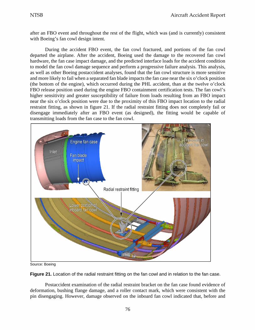
NTSB Aircraft Accident Report
76
after an FBO event and throughout the rest of the flight, which was (and is currently) consistent with Boeing’s fan cowl design intent.
During the accident FBO event, the fan cowl fractured, and portions of the fan cowl departed the airplane. After the accident, Boeing used the damage to the recovered fan cowl hardware, the fan case impact damage, and the predicted interface loads for the accident condition to model the fan cowl damage sequence and perform a progressive failure analysis. This analysis, as well as other Boeing postaccident analyses, found that the fan cowl structure is more sensitive and more likely to fail when a separated fan blade impacts the fan case near the six o’clock position (the bottom of the engine), which occurred during the PHL accident, than at the twelve o’clock FBO release position used during the engine FBO containment certification tests. The fan cowl’s higher sensitivity and greater susceptibility of failure from loads resulting from an FBO impact near the six o’clock position were due to the proximity of this FBO impact location to the radial restraint fitting, as shown in figure 21. If the radial restraint fitting does not completely fail or disengage immediately after an FBO event (as designed), the fitting would be capable of transmitting loads from the fan case to the fan cowl.
Source: Boeing
Figure 21. Location of the radial restraint fitting on the fan cowl and in relation to the fan case.
Postaccident examination of the radial restraint bracket on the fan case found evidence of deformation, bushing flange damage, and a roller contact mark, which were consistent with the pin disengaging. However, damage observed on the inboard fan cowl indicated that, before and
NTSB Aircraft Accident Report
77
after the pin disengaged, load was transmitted to the fan cowl through the radial restraint bracket and fitting, both of which remained mostly intact and in contact.
During the accident sequence, the separated fan blade’s impact with the fan case near the six o’clock position transmitted FBO-generated impact loads through the radial restraint fitting into the fan cowl structure, causing the fan cowl to deform and fracture. These transmitted loads were greater than originally predicted based on the assumption of a completely failed radial restraint fitting that provided no load path to the fan cowl. Thus, the transmitted loads and associated stresses were not accounted for in the structural analyses performed as part of certification, which is further discussed in section 2.3. The loads imparted through the radial restraint fitting into the fan cowl structure also created skin cracks in the lower part of the fan cowl that propagated (during the engine surge and rundown phases) until the three latch assembly load paths failed, the fan cowl halves disengaged from each other, and portions of the fan cowl departed the airplane.
Boeing’s postaccident analysis of the fan cowl (which was conducted using modeling tools that were not available at the time of certification) determined that the impact loads and associated stresses from the released fan blade after reaching the fan cowl structure caused the residual strength of the damaged fan cowl structure to be exceeded. The NTSB concludes that portions of the fan cowl departed the airplane because (1) the impact of the separated fan blade with the fan case imparted significant loads into the fan cowl through the radial restraint fitting and (2) the associated stresses in the fan cowl structure exceeded the residual strength of the fan cowl, causing its failure.
One portion of the fan cowl that was recovered after the accident was the inboard aft latch keeper. The left side of the fuselage near the location of the missing cabin window (adjacent to seat 14A) had impact damage and witness marks that were consistent with the size and shape of the inboard aft latch keeper and surrounding fan cowl structure, as shown in figure 6.
The skin stresses associated with loads transmitted to the fan cowl through the radial restraint fitting resulted in fractures initiating around the latches on the inboard fan cowl. These fractures eventually caused the inboard fan cowl structure surrounding the aft and middle latch keepers to separate. The separation of the forward latch assembly quickly followed, which allowed the fan cowls to open. The aft latch assembly (the latch keeper and latch hook) remained engaged as air loads caused both fan cowl halves to continue to open, and the aft latch keeper (on the inboard fan cowl), its surrounding support structure, and part of the inboard fan cowl skin were flung up and over the engine and the left wing. The aft latch assembly then separated, and the inboard fan cowl piece with the aft latch keeper impacted the fuselage near the window by seat 14A, as shown in figure 22. The NTSB concludes that the impact of the inboard fan cowl aft latch keeper with the fuselage near the cabin window adjacent to seat 14A caused the window to depart the airplane, the rapid depressurization of the cabin, and the passenger fatality.
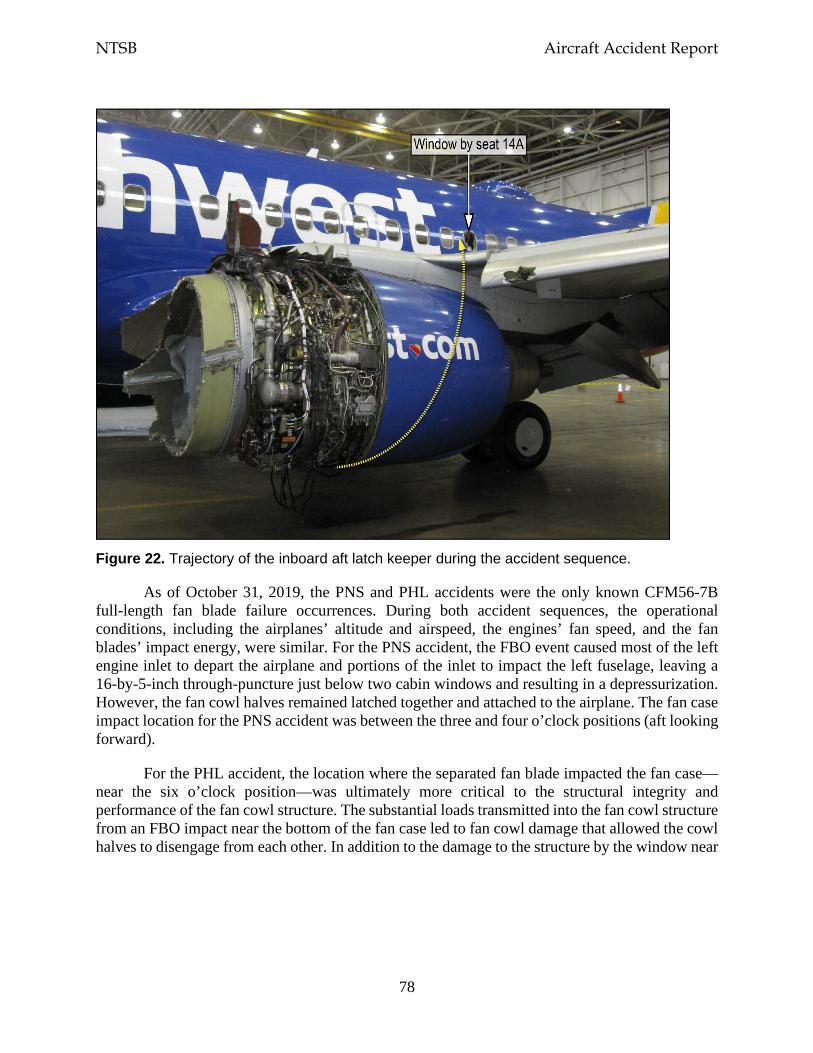
NTSB Aircraft Accident Report
78
Figure 22. Trajectory of the inboard aft latch keeper during the accident sequence.
As of October 31, 2019, the PNS and PHL accidents were the only known CFM56-7B full-length fan blade failure occurrences. During both accident sequences, the operational conditions, including the airplanes’ altitude and airspeed, the engines’ fan speed, and the fan blades’ impact energy, were similar. For the PNS accident, the FBO event caused most of the left engine inlet to depart the airplane and portions of the inlet to impact the left fuselage, leaving a 16-by-5-inch through-puncture just below two cabin windows and resulting in a depressurization. However, the fan cowl halves remained latched together and attached to the airplane. The fan case impact location for the PNS accident was between the three and four o’clock positions (aft looking forward).
For the PHL accident, the location where the separated fan blade impacted the fan case—near the six o’clock position—was ultimately more critical to the structural integrity and performance of the fan cowl structure. The substantial loads transmitted into the fan cowl structure from an FBO impact near the bottom of the fan case led to fan cowl damage that allowed the cowl halves to disengage from each other. In addition to the damage to the structure by the window near
NTSB Aircraft Accident Report
79
seat 14A, other structures (including the left wing and the left horizontal stabilizer) were damaged by departing inlet and fan cowl parts.116
The circumstances of this accident indicated the potential for other Boeing 737NG-series airplanes (the 737-600, -700, -800, and -900) to receive significant damage resulting from an FBO event if the fan blade impact occurred at a critical location. The NTSB concludes that this accident demonstrated the susceptibility of the fan cowl installed on Boeing 737NG-series airplanes to an FBO impact location near the radial restraint fitting and the effects of such an impact on the structural integrity of the fan cowl.
It is important that the interaction of the fan case, radial restraint fitting, and fan cowl during an FBO event be well understood to preclude a failure of the fan cowl structure. Therefore, the NTSB recommends that the FAA require Boeing to determine the critical fan blade impact location(s) on the CFM56-7B engine fan case and redesign the fan cowl structure on all Boeing 737NG-series airplanes to ensure the structural integrity of the fan cowl after an FBO event. The NTSB also recommends that, once the actions requested in Safety Recommendation A-19-17 are completed, the FAA require Boeing to install the redesigned fan cowl structure on new-production 737NG-series airplanes. The NTSB further recommends that, once the actions requested in Safety Recommendation A-19-17 are completed, the FAA require operators of Boeing 737NG-series airplanes to retrofit their airplanes with the redesigned fan cowl structure.
This investigation revealed the concept of a critical location for an FBO impact and its effect on the structural integrity of the engine nacelle and its components (which include the inlet, fan cowl, and thrust reversers). Other engine/airframe combinations may also be sensitive to the location of an FBO impact and have unintended load paths and/or loads that are greater than those accounted for in structural analyses. No FAA regulation (including those discussed in section 1.3.5.3) currently requires manufacturers, as part of the design of the nacelle structure, to account for critical FBO impact locations in all engine operating conditions. Therefore, the NTSB recommends that the FAA expand the 14 CFR Part 25 and 33 certification requirements to mandate that airplane and engine manufacturers work collaboratively to (1) analyze all critical fan blade impact locations for all engine operating conditions, the resulting fan blade fragmentation, and the effects of the FBO-generated loads on the nacelle structure and (2) develop a method to ensure that the analysis findings are fully accounted for in the design of the nacelle structure and its components.
In addition, the NTSB recommends that EASA expand its certification requirements for transport-category airplanes and aircraft engines to mandate that airplane and engine manufacturers work collaboratively to (1) analyze all critical fan blade impact locations for all engine operating conditions, the resulting fan blade fragmentation, and the effects of the FBO-generated loads on the nacelle structure and (2) develop a method to ensure that the analysis findings are fully accounted for in the design of the nacelle structure and its components.
116 As stated in section 1.3.4, the left-wing leading edges and upper and lower surfaces and the left horizontal
stabilizer showed evidence of impact damage.
NTSB Aircraft Accident Report
80
2.3 Certification Summary
CFM conducted two engine FBO containment certification tests to meet the requirements of section 33.94, Blade Containment and Rotor Unbalance Tests. As part of these requirements, CFM had to demonstrate that (1) the engine case would be capable of containing damage without catching fire and without failure of the engine mounting attachments when the engine was operated for at least 15 seconds after an FBO event and (2) the engine could be successfully shut down, or the damage could result in a self-shutdown of the engine. The tests were successfully completed, and the engine was certificated in December 1996.
CFM provided data from the engine FBO containment certification tests (and the engine FBO rig tests) to Boeing to use in the design of the inlet and fan cowl. Boeing then performed structural analyses to assess how the inlet, fan cowl, and other airplane structures would respond to an FBO event. These analyses, which included finite element models, were performed using the state-of-the-art analytical modeling tools that were available at the time. Boeing used the available test data (which included test damage documentation) and the results of the subsequent analyses to design the airplane structure to withstand an initial fan blade release and subsequent damage as a result of an FBO event and ensure that the airplane would be capable of safe flight and landing. Boeing’s design philosophy was that the failure of an engine fan blade and any resulting damage should not cause the inlet, fan cowl, or their components to separate and present a hazard to the airplane. In December 1997, the airplane structure was certificated in accordance with the requirements of Part 25.
Given the available test data, the subsequent structural analyses, and the analytical modeling tools available at the time that the engine and the airplane were certificated, the effects of an FBO event were assumed to have been well defined. However, as stated in sections 2.2.2 and 2.2.3, FBO-related events occurred during the accident sequence that were not anticipated or accounted for in the structural analyses, including the following:
• the fan blade fragments that traveled forward of the fan case had a trajectory angle (relative to the circumferential direction) that was greater than that observed during the engine FBO containment certification tests;
• the inlet damage caused by the forward-traveling fan blade fragments was greater than that observed during the engine FBO containment certification tests and accounted for in the certification analyses;
• FBO-generated loads were transmitted to the fan cowl through the radial restraint fitting, which was not accounted for in the fan cowl’s design; and
• the stresses in the fan cowl were greater than those calculated in the certification analyses.
The engine FBO containment certification tests were intended to demonstrate the engine’s radial containment capability under the most critical engine operating conditions, including the maximum permissible rotor speed (per section 33.94) and the peak operational stresses and temperature. The tests were not intended to demonstrate or account for all possible operating conditions or the effects that various fan blade impact locations could have on the airplane structure. The NTSB concludes that, given the results of CFM’s engine FBO containment

NTSB Aircraft Accident Report
81
certification tests and Boeing’s subsequent structural analyses of the effects of an FBO event on the airframe, the post-FBO events that occurred during this accident could not have been predicted.
New technologies and analytical methods have been developed since the CFM56-7B engine and the Boeing 737-700 airplane were certificated. These technologies and methods are currently being used by engine and airframe manufacturers to more effectively model an FBO event, correlate test and analysis results, and predict the damages and stress levels associated with various fan blade release locations and operating conditions.
As part of this investigation, Boeing and CFM jointly developed analytical models using the most recent state-of-the-art methods to predict, confirm, and correlate the behavior of the CFM56-7B engine and the 737-700 airplane structure during the accident FBO event. The analytical models considered the operating conditions that the accident engine, inlet, and fan cowl experienced when the fan blade separation occurred as well as the certification test results. The most recent state-of-the-art methods enabled assessments of the effects of the fan blade fragments’ impact with the fan case, the effects of the resulting displacement wave, the progressive failure of the inlet and the fan cowl, and the relationship between the inlet and fan cowl failure sequences, as discussed in sections 1.3.7.2 and 1.3.7.3.
The NTSB recognizes that the effects of the fan blade fragments’ impact with the fan case and the resulting displacement wave were also modeled as part of the Boeing 737-700 airplane certification. However, the structural analysis modeling tools associated with the postaccident analyses had advanced technological capabilities that had not been developed at the time of certification. Among other things, the advanced capabilities enabled analyses that captured the incremental effects (during a very short period of time) of an FBO event, which made the analyses more predictive and representative of actual operating conditions. The NTSB concludes that the structural analysis modeling tools that currently exist to analyze an FBO event and predict the subsequent engine and airframe damage will allow airplane manufacturers to better understand the interaction of the engine and airframe during an FBO event and the response of the inlet, fan cowl, and associated structures in the airplane’s normal operating envelope.
2.4 Operational Factors
2.4.1 Checklist Performance
At the time of the engine failure (1103:33), the first officer was the pilot flying, and the captain was the pilot monitoring. FDR data showed that the left engine’s thrust lever was moved to the idle position 25 seconds after the engine failure occurred (1103:58) and that the engine start lever was moved to the fuel cutoff position 11 seconds later (1104:09).
At 1109:30, the captain indicated that she would assume the role of the pilot flying and that the first officer (as the pilot monitoring) should begin the Engine Fire or Engine Severe Damage or Separation non-normal checklist (shown in figure 17). The flight crew began the formal execution of that checklist at 1109:52, which was about 6 minutes after the time of the engine
NTSB Aircraft Accident Report
82
failure.117 However, between the time of the engine failure and the start of the checklist, the flight crew was primarily focused on maintaining airplane control during the emergency descent, navigating toward an emergency landing airport, and communicating with ATC.118 Further, guidance in the SWA 737NG QRH states that “non-normal checklist use starts when the aircraft flight path and configuration are correctly established...usually time is available to assess the situations before corrective action is started.”
The 14-item Engine Fire or Engine Severe Damage or Separation checklist did not have any immediate action (memory) items. Nevertheless, the flight crew recognized the two checklist items that needed to be immediately performed: moving the left engine’s thrust lever to the idle position (step 2) and moving the engine start lever to the fuel cutoff position (step 3). The CVR showed that the first five checklist items were completed by 1111:00, which was 1 minute 8 seconds after the checklist was initiated.119
The last item that the flight crew accomplished on this checklist was to start the APU (step 10), which occurred about 6.5 minutes (1116:16) after the checklist began. The remaining items on the checklist were to balance the fuel (as needed), change the transponder mode selector from “TA/RA” (traffic advisory/resolution advisory) to “TA,” change the isolation valve switch to auto, and plan to land at the nearest suitable airport. The NTSB notes that, although the flight crew did not discuss the plan to land at the nearest suitable airport as part of the checklist (step 14), the crewmembers had discussed, between themselves and with ATC, landing at PHL before initiating the checklist.120 The flight crew’s nonperformance of the other three items on the checklist had no adverse effect on the outcome of the emergency.
The flight crew did not call for or complete (using the standard checklist procedure) the three other non-normal checklists that applied to the circumstances of this accident: the One Engine Inoperative Landing checklist, which is required after the Engine Fire or Engine Severe Damage or Separation checklist; the Cabin Altitude Warning or Rapid Depressurization checklist, which is required if the cabin altitude warning light or horn annunciates; and the Emergency Descent checklist, which is required by a step in the Cabin Altitude Warning or Rapid Depressurization checklist. However, the captain was permitted to deviate from normal procedures, including the performance of checklists, in an emergency situation. Section 121.557, Emergencies: Domestic and Flag Operations, states the following in paragraph (a):
In an emergency situation that requires immediate decision and action the pilot in command may take any action that [the pilot] considers necessary under the circumstances. In such a case [the pilot] may deviate from prescribed operations
117 Although the flight crew began executing the Engine Fire or Engine Severe Damage or Separation checklist
about 6 minutes after the engine failure occurred, the captain had stated, “I'm going to go through [the] Q-R-H” about 2 minutes after the engine failure occurred.
118 During that time, the airplane descended from FL320 to an altitude of 13,600 ft. 119 As stated in section 1.9.1, the first five items on the Engine Fire or Engine Severe Damage or Separation
checklist were considered to be quick reference (time-sensitive) items. 120 The CVR recorded the captain’s statement to ATC, “we’re looking at Philly,” more than 4 minutes before the
flight crew began the Engine Fire or Engine Severe Damage or Separation checklist.
NTSB Aircraft Accident Report
83
procedures and methods, weather minimums, and this chapter, to the extent required in the interests of safety.[121]
SWA’s Flight Operations Manual, section 5.1.4, provides the following similar information:
In an emergency situation that requires immediate decision and action, the Captain may take any action necessary under the circumstances. In such a case, the Captain may deviate from Southwest Airlines’ operations procedures and methods, weather minimums, and regulations to the extent required in the interests of safety.
The One Engine Inoperative Landing non-normal checklist (shown in figure 18) had no immediate action items. The first item on the checklist instructed the flight crew to plan for a flaps 15 landing. However, because of airplane controllability concerns, the captain decided to conduct a flaps 5 landing to ensure that the airplane’s airspeed would not get too slow. Even though the checklist and the Aircraft Operating Manual indicated that a flaps 15 landing should be conducted with one engine inoperative, the decision to conduct a flaps 5 landing was within the captain’s authority. The flight crew’s nonperformance of this checklist had no adverse effect on the outcome of the emergency.
The Cabin Altitude Warning or Rapid Depressurization non-normal checklist (shown in figure 19) had two immediate action items—don oxygen masks and set regulators to 100% (step 1) and establish crew communications (step 2)—that the flight crew performed from memory. The CVR recorded sounds consistent with breathing through oxygen masks at 1104:49, which was 1 minute 16 seconds after the engine failure occurred, but the flight crewmembers might have donned their oxygen masks before then given that the CVR recorded unintelligible cockpit communications between 1103:42 and 1104:41. During postaccident interviews, the crewmembers reported some initial confusion about the position of the switch that allowed them to communicate through a microphone in their oxygen mask. According to CVR information, at 1104:54, the flight crewmembers had established communications through their oxygen masks. The nonperformance of the next three items on the checklist, which were quick reference (time-sensitive) items, as well as the deferred items after checklist completion had no adverse effect on the outcome of the emergency.122
The Emergency Descent non-normal checklist (shown in figure 20) had three quick reference (time-sensitive) items that the flight crew performed independently of the checklist. (The checklist had no immediate action items.) First, the checklist indicated that the flight crew should advise the flight attendants and ATC about the emergency descent (step 1), and the CVR recorded the captain stating to ATC, at 1104:54, “Southwest thirteen eighty has an engine fire descending.”123 Second, the checklist stated that the airplane should descend, without delay, to 10,000 ft or the lowest safe altitude, whichever is higher (step 3). FDR data showed that, 25 seconds after the engine failure and 8 seconds after the airplane’s roll attitude was generally
121 “This chapter” refers to the requirements for domestic, flag, and supplemental operations in Title 14
Chapter I—Federal Aviation Administration, Department of Transportation. 122 Step 6 of the checklist did not apply because the cabin altitude was not controllable at the time. 123 The first officer discussed the emergency situation with a flight attendant about 10 minutes afterward.
NTSB Aircraft Accident Report
84
back under the pilots’ control, the emergency descent started, and the airplane descended through 10,000 ft about 8 minutes after the emergency descent began. Last, the checklist indicated that both thrust levers should be moved so that thrust is reduced to minimum (step 5), and the FDR showed that both thrust levers were moved to the idle position 25 seconds after the engine failure.
Given the emergency situation caused by the engine failure, the resulting airplane damage, and the rapid depressurization, the nonperformance of all but one of the remaining items on the checklist did not affect the situation. The one item on this checklist that could have affected the situation involved the deployment of the speedbrakes to the flight detent position (step 6) because that could have allowed a more rapid descent without additional airspeed (which the captain was avoiding due to airplane vibration) and could have facilitated a quicker landing at MDT, which was the geographically closer airport at the time. (The flight crew’s selection of PHL as the emergency landing airport is discussed in the next section.) However, the time that might have been saved would not likely have changed the outcome of the emergency. In addition, speedbrake deployment could have negatively impacted the aerodynamics of the damaged engine and wing, which would have caused additional stability and control issues for the flight crew.
During postaccident interviews, the captain and the first officer indicated that they were focused on maintaining control of the airplane, which was the first action listed in SWA’s Flight Operations Manual for all non-normal situations (see section 1.9.1). Maintaining airplane control was the most critical demand placed on the flight crew once the emergency situation occurred. Specifically, the crew had to control an airplane that had lost thrust on the left side and was simultaneously experiencing greatly increased drag on the same side because of the damage that resulted from the engine failure. Also, immediately after the engine failure, the airplane entered a rapid roll to the left, which reached 41.3° within 11 seconds, and experienced positive and negative vertical accelerations. FDR data showed that significant control input forces in all three axes of flight were necessary to maintain control of the damaged airplane.
In addition to maintaining airplane control, communications with ATC—beyond those related to headings, altitudes, and clearances—imposed demands on a task-saturated flight crew (even though the intent of those communications was to provide assistance to the crew and follow ATC procedures). For example, according to CVR information, during the 17 minutes between the time of the engine failure and the time that the airplane landed, the crew was given four frequency changes.124 Also, ATC asked the crew multiple times to state the following: the nature of the emergency, including whether the engine was on fire; the number of occupants aboard; the amount fuel on board (which the flight crew provided in hours and was then asked to provide in pounds); and the ARFF support that would be needed after landing.
Even with the additional demands placed on the flight crew as a result of the engine failure, the CVR recorded the first officer’s concern about performing checklists. Specifically, at 1111:45, the first officer stated, “we’re gonna need a few minutes right? To run a couple checklists? Is that right?” The captain replied, 4 seconds later, “nope, just keep goin’.” Also, the first officer stated, at 1113:51, “we got a couple of checklists to run.” However, at 1115:54, after learning about the
124 After the third frequency change, the CVR recorded the captain’s statement to the approach controller, “we
need a single channel no more channel switching.” Another frequency change occurred 3.5 minutes later when the approach controller handed off the flight to the tower controller.
NTSB Aircraft Accident Report
85
passenger injury, the captain stated, “let’s get it turned in.” During a postaccident interview, the captain stated that she had initially requested a long final approach to allow time to accomplish checklists but then decided to expedite the approach due to the passenger injury.
The NTSB concludes that performing required checklists according to standard operating procedures is a critical part of safe flight operations. However, given the emergency situation aboard this flight, the flight crew’s performance of most, but not all, of the items on the Engine Fire or Engine Severe Damage or Separation non-normal checklist and the nonperformance of the three other relevant non-normal checklists allowed the crew to appropriately balance the procedural requirement of executing checklists with the high workload associated with maintaining airplane control and accomplishing a safe and timely descent and landing.
2.4.2 Emergency Landing Airport Selection
At 1105:07 (1 minute 34 seconds after the engine failure), after learning about the emergency situation aboard the airplane, the center controller asked the flight crewmembers which airport they would like to divert to, and the captain stated, “give us a vector for your closest.” The ATC transcript showed that the controller suggested MDT, but the CVR did not record most of this transmission. Thus, it is possible that the flight crew did not hear the controller’s suggestion to divert to MDT, especially given the increased background noise recorded on the CVR and the significant airplane vibration reported during flight crew postaccident interviews.
Six seconds after the captain requested a vector to the closest airport, the CVR recorded the controller providing the vector to MDT. Three seconds later, the CVR recorded the captain acknowledging the vector and stating, “we’re looking at ah Philly.” Afterward, the controller cleared the airplane direct to PHL.
The straight-line distance to PHL (57 nm) was about twice the distance to MDT (29 nm) based on the airplane’s location at the time of the engine failure. The captain stated, during a postaccident interview, that she was unable to conduct the emergency descent at the recommended speed (VMO) due to airplane vibration. The reduced airspeed resulted in a descent rate that would not have significantly affected the time needed to land at either MDT or PHL.125 Although the airplane would have traveled a shorter distance to MDT than it did to PHL (because MDT was geographically closer at the time), the time required to descend from FL320 would basically have been the same regardless of whether MDT or PHL was the emergency landing airport. FDR data showed a near-continuous descent from FL320 to PHL with no intermediate level-off altitudes, which was a desirable descent profile for the emergency situation.
The last step of the Engine Fire or Engine Severe Damage or Separation checklist instructed flight crews to plan to land at the nearest suitable airport. Regarding the “nearest suitable airport” reference, the SWA 737NG QRH defined “nearest airport” as the “nearest airport in point of time” and “suitable airport” as “the most suitable airport to handle the non-normal situation.” It
125 The descent rate from flight level 320 to an altitude of about 11,500 ft averaged about 3,000 feet per minute.
The descent rate below 11,500 ft averaged about 1,500 feet per minute.
NTSB Aircraft Accident Report
86
is noteworthy that the QRH definition of nearest airport included “in point of time” and that the NTSB found that the difference in time for landing at MDT or PHL was negligible.126 In addition, the QRH included “On-line versus Off-line Airport” as one of the factors to be evaluated when determining airport suitability. PHL was an on-line airport for SWA (that is, an airport to and from which SWA provides service) and, as such, could provide greater operational and customer service support compared with an off-line airport (such as MDT).
PHL had two other characteristics that made it a more suitable airport than MDT for this emergency situation. First, PHL had four runways, whereas MDT had one runway, and the longest runway at PHL was 2,000 ft longer than the runway at MDT.127 Second, PHL was an ARFF index E airport, indicating the highest level of ARFF capabilities under section 139.317, whereas MDT had a lower ARFF index (B).
Both the Federal Aviation Regulations and SWA’s written policy (see section 1.9.1) gave the crew broad discretion to choose an emergency landing airport based on the immediate operational and safety concerns. During a postaccident interview, the first officer stated that he looked at a map, determined that PHL was a close suitable airport, and pointed out that information to the captain.128 The NTSB concludes that the flight crew’s decision to land at PHL was appropriate given the airplane’s location at the time of the emergency, the circumstances of the emergency, and the airport’s multiple runways and ARFF capabilities.
2.5 Occupant Safety During Emergency Landings
Even with the loud conditions in the cabin, all three flight attendants reported that they heard the captain’s PA announcement at 1105:52 indicating that the airplane was diverting to PHL. Direct contact between the flight attendants and the flight crew was established at 1115:04 (about 5.5 minutes before landing). During the conversation, a flight attendant asked, “are we almost there?” and the first officer stated, “we’re gonna land as soon as we can.” At 1115:45, the flight attendant advised the passengers “we are almost landing” and, about 1 minute later, “we are almost there.”
Although the flight attendants were aware of the imminent landing, none was in her assigned jumpseat in preparation for the landing. Flight attendant A, who was assigned to the forward entry door position, stated that she did not have time to return to her jumpseat, so she sat on the aisle floor near row 4 or 5, and seated passengers held her down. Flight attendant B, who was assigned to the aft galley position, stated that she sat on the floor in the aft galley with seated
126 As stated in section 1.9.1, the SWA 737NG QRH definition of “nearest airport” also indicated that two airports
of different distances could be considered equal if the same amount of time would be required to arrive at either airport.
127 The airplane landed on runway 27L at PHL. Runway 9R/27L, the longest runway at PHL, was 12,000 ft in length. MDT runway 13/31 was about 10,000 ft in length. The 12,000-ft runway provided an additional safety margin given that the airplane landed with partial flaps, which required a greater-than-normal landing speed and distance.
128 The CVR recorded the captain stating to the first officer, at 1217:48 (which was almost 1 hour after the airplane landed), “Philly was a great call on your part. Excellent call.”
NTSB Aircraft Accident Report
87
passengers holding her down during landing.129 Flight attendant C, who was assigned to the forward galley door position, stated that she also sat on the floor in the aft galley.130
SWA training personnel stated that flight attendants were instructed that they needed to be in their jumpseat during landing because it was the “safest, most secure place for them,” especially if an airplane evacuation was necessary. Guidance in the company’s flight attendant manual reinforced that flight attendants needed to be seated in their assigned jumpseats with their seat belts and shoulder harnesses fastened for every takeoff and landing. The manual also stated that, during a planned emergency landing, flight attendants must occupy their jumpseats. SWA acknowledged that it was acceptable for a flight attendant to be out of an assigned jumpseat for landing in limited situations, including providing first aid in a life-threatening medical situation. However, for this event, first aid for the injured passenger was being administered by medically qualified passengers.
The emergency landing occurred with good weather and during daytime conditions, so routine cues associated with an imminent landing (the airplane’s descent and configuration for landing) would have been available to the flight attendants before they sat on the floor of the cabin. The flight attendants’ brace commands to passengers (“heads down, stay down”), which began 19 seconds before landing, demonstrated that the flight attendants understood that landing was imminent. However, because the flight attendants were not secured in their assigned jumpseats, they could have been injured if an adverse landing event (such as a runway excursion) had occurred, which could have hindered the flight attendants’ ability to rapidly evacuate the airplane.
This emergency situation involved an airplane with an unknown amount of damage and minimal contact with the flight crewmembers, who were busy controlling the airplane and performing other related tasks. As a result, once the injured passenger began receiving first aid from medically qualified passengers, the flight attendants should have focused on securing the cabin and themselves for the emergency landing and preparing themselves for the possibility of an evacuation. The NTSB concludes that, although not a factor in the outcome of this accident, the flight attendants should have been properly restrained in their assigned jumpseats in case an emergency evacuation after landing was necessary.
The NTSB recognizes that the accident flight was challenging for all of the crewmembers because of the acute emergency situation involving trauma, airplane damage, depressurization, noise, communication challenges, and time pressure. However, it is important to remind flight attendants of the challenges of managing an emergency situation while maintaining readiness to perform a rapid evacuation, which is a flight attendant’s most critical responsibility.131
129 The NTSB recognizes that the dual-position jumpseat in the aft galley was occupied by one of the passengers
who was previously seated in either seat 14B or 14C and an SWA company employee. The issue of reseating passengers affected by an in-flight loss of seating capacity is discussed later in this section.
130 The dual-position jumpseat in the forward galley, where flight attendants A and C were assigned, was unoccupied for landing.
131 On October 6, 2016, the NTSB issued Safety Recommendation A-16-25 as a result of its investigation of the March 2015 runway excursion accident involving a Delta Air Lines Boeing MD-88 in New York, New York. Safety Recommendation A-16-25 asked the FAA to “require 14 Code of Federal Regulations Part 121 operators to provide (1) guidance that instructs flight attendants to remain at their assigned exits and actively monitor exit availability in
NTSB Aircraft Accident Report
88
The NTSB’s postaccident discussions with SWA revealed that the operator has not incorporated the lessons learned from this accident in its initial and recurrent flight attendant training programs. Therefore, the NTSB recommends that SWA include the lessons learned from the accident involving Southwest Airlines flight 1380 in initial and recurrent flight attendant training, emphasizing the importance of being secured in a jumpseat during emergency landings.
The accident flight was full, with no open cabin seats remaining, and the flight attendants needed to reseat the passengers in seats 14B and 14C so that the injured passenger (in seat 14A) could receive medical care. Both affected passengers went to the aft galley; one passenger sat on the flight attendant aft jumpseat, and the other sat on the floor. (The other aft jumpseat was occupied by an SWA company employee.) The SWA flight attendant manual included numerous references about reseating passengers but did not address a situation in which no additional seats were available. Postaccident interviews with SWA training personnel revealed that options for reseating passengers aboard a full flight had not been adequately considered as part of safety risk management. A review of FAA regulations, ACs, and Order 8900.1 (Flight Standards Information Management System) did not identify any specific guidance addressing options for reseating passengers when no additional passenger seats are available. The NTSB concludes that FAA guidance addressing options for reseating passengers if an in-flight loss of seating capacity were to occur would help air carriers implement procedures to address this situation. Therefore, the NTSB recommends that the FAA develop and issue guidance on ways that air carriers can mitigate hazards to passengers affected by an in-flight loss of seating capacity.
all non-normal situations in case an evacuation is necessary and (2) flight attendant training programs that include scenarios requiring crew coordination regarding active monitoring of exit availability and evacuating after a significant event that involves a loss of communications.” The recommendation was classified “Open—Acceptable Response” on March 27, 2017.
NTSB Aircraft Accident Report
89
3. Conclusions 3.1 Findings
• None of the following were factors in this accident: (1) flight crew qualifications, which were in accordance with US regulations; (2) flight crew medical conditions; (3) the airworthiness of the airplane before the left engine failure occurred; and (4) Southwest Airlines’ maintenance of the airplane.
• The low-cycle fatigue crack in the fan blade dovetail initiated because of higher-than-expected dovetail stresses under normal operating loads, and this crack was most likely not detectable during the fluorescent penetrant inspection at the time of the fan blade set’s last overhaul and subsequent visual inspections at the time of fan blade relubrications.
• The requirement to perform an eddy current inspection at the time of fan blade overhaul and an ultrasonic inspection at the time of blade relubrication should enable cracked fan blades in CFM56-7B engines to be detected and removed from service before the cracks reach a critical size and the blades fracture.
• The fan blade fragments that traveled forward of the fan case, along with the displacement wave created by the fan blade’s impact with the fan case, caused damage that compromised the structural integrity of the inlet and caused portions of the inlet to depart from the airplane.
• Portions of the fan cowl departed the airplane because (1) the impact of the separated fan blade with the fan case imparted significant loads into the fan cowl through the radial restraint fitting and (2) the associated stresses in the fan cowl structure exceeded the residual strength of the fan cowl, causing its failure.
• The impact of the inboard fan cowl aft latch keeper with the fuselage near the cabin window adjacent to seat 14A caused the window to depart the airplane, the rapid depressurization of the cabin, and the passenger fatality.
• This accident demonstrated the susceptibility of the fan cowl installed on Boeing 737 next-generation-series airplanes to a fan-blade-out impact location near the radial restraint fitting and the effects of such an impact on the structural integrity of the fan cowl.
• Given the results of CFM’s engine fan-blade-out (FBO) containment certification tests and Boeing’s subsequent structural analyses of the effects of an FBO event on the airframe, the post-FBO events that occurred during this accident could not have been predicted.
• The structural analysis modeling tools that currently exist to analyze a fan-blade-out (FBO) event and predict the subsequent engine and airframe damage will allow airplane manufacturers to better understand the interaction of the engine and airframe during an
NTSB Aircraft Accident Report
90
FBO event and the response of the inlet, fan cowl, and associated structures in the airplane’s normal operating envelope.
• Performing required checklists according to standard operating procedures is a critical part of safe flight operations. However, given the emergency situation aboard this flight, the flight crew’s performance of most, but not all, of the items on the Engine Fire or Engine Severe Damage or Separation non-normal checklist and the nonperformance of the three other relevant non-normal checklists allowed the crew to appropriately balance the procedural requirement of executing checklists with the high workload associated with maintaining airplane control and accomplishing a safe and timely descent and landing.
• The flight crew’s decision to land at Philadelphia International Airport was appropriate given the airplane’s location at the time of the emergency, the circumstances of the emergency, and the airport’s multiple runways and aircraft rescue and firefighting capabilities.
• Although not a factor in the outcome of this accident, the flight attendants should have been properly restrained in their assigned jumpseats in case an emergency evacuation after landing was necessary.
• Federal Aviation Administration guidance addressing options for reseating passengers if an in-flight loss of seating capacity were to occur would help air carriers implement procedures to address this situation.
3.2 Probable Cause
The National Transportation Safety Board determines that the probable cause of this accident was a low-cycle fatigue crack in the dovetail of fan blade No. 13, which resulted in the fan blade separating in flight and impacting the engine fan case at a location that was critical to the structural integrity and performance of the fan cowl structure. This impact led to the in-flight separation of fan cowl components, including the inboard fan cowl aft latch keeper, which struck the fuselage near a cabin window and caused the window to depart from the airplane, the cabin to rapidly depressurize, and the passenger fatality.
NTSB Aircraft Accident Report
91
4. Recommendations To the Federal Aviation Administration
Require Boeing to determine the critical fan blade impact location(s) on the CFM56-7B engine fan case and redesign the fan cowl structure on all Boeing 737 next-generation-series airplanes to ensure the structural integrity of the fan cowl after a fan-blade-out event. (A-19-17)
Once the actions requested in Safety Recommendation A-19-17 are completed, require Boeing to install the redesigned fan cowl structure on new-production 737 next-generation-series airplanes. (A-19-18)
Once the actions requested in Safety Recommendation A-19-17 are completed, require operators of Boeing 737 next-generation-series airplanes to retrofit their airplanes with the redesigned fan cowl structure. (A-19-19)
Expand the Title 14 Code of Federal Regulations Part 25 and 33 certification requirements to mandate that airplane and engine manufacturers work collaboratively to (1) analyze all critical fan blade impact locations for all engine operating conditions, the resulting fan blade fragmentation, and the effects of the fan-blade-out-generated loads on the nacelle structure and (2) develop a method to ensure that the analysis findings are fully accounted for in the design of the nacelle structure and its components. (A-19-20)
Develop and issue guidance on ways that air carriers can mitigate hazards to passengers affected by an in-flight loss of seating capacity. (A-19-21)
To Southwest Airlines
Include the lessons learned from the accident involving Southwest Airlines flight 1380 in initial and recurrent flight attendant training, emphasizing the importance of being secured in a jumpseat during emergency landings. (A-19-22)
To the European Aviation Safety Agency
Expand your certification requirements for transport-category airplanes and aircraft engines to mandate that airplane and engine manufacturers work collaboratively to (1) analyze all critical fan blade impact locations for all engine operating conditions, the resulting fan blade fragmentation, and the effects of the fan-blade-out-generated loads on the nacelle structure and (2) develop a method to ensure that the analysis findings are fully accounted for in the design of the nacelle structure and its components. (A-19-23)
NTSB Aircraft Accident Report
92
BY THE NATIONAL TRANSPORTATION SAFETY BOARD
ROBERT L. SUMWALT, III JENNIFER HOMENDY Chairman Member
BRUCE LANDSBERG Vice Chairman
Adopted: November 19, 2019
NTSB Aircraft Accident Report
93
5. Appendixes Appendix A: Investigation and Hearing
The National Transportation Safety Board (NTSB) was notified of this accident about 1307 eastern daylight time on April 17, 2018. An investigative team arrived at Philadelphia International Airport (PHL), Philadelphia, Pennsylvania, about 1630 that day. Chairman Robert Sumwalt accompanied the team to PHL. On-scene investigative groups were formed in the areas of operations, powerplants, structures, and survival factors. Specialists were assigned to perform the readout of the cockpit voice recorder and the flight data recorder at the NTSB’s laboratory in Washington, DC. Specialists in the areas of meteorology, maintenance records, air traffic control, and metallurgy also supported the investigation.
Parties to the investigation were the Federal Aviation Administration (FAA), Boeing, CFM International, Southwest Airlines (SWA), Southwest Airlines Pilots Association, Collins Aerospace (formerly UTC Aerospace Systems), Transport Workers Union Local 556, and Aircraft Mechanics Fraternal Association. In accordance with the provisions of Annex 13 to the Convention on International Civil Aviation, the Bureau d’Enquêtes et d’Analyses pour la Sécurité de l’Aviation Civile (BEA), the NTSB’s counterpart agency in France, participated in the investigation as the accredited representative of the state of design and manufacture for the engines, and Safran Aircraft Engines participated in the investigation as a technical advisor to the BEA.
The NTSB held an investigative hearing for this accident on November 14, 2018. Issues discussed at the hearing included CFM56-7-series engine fan blade design and development history, CFM56-7-series engine fan blade inspection methods and procedures, and engine fan-blade-out containment design and certification criteria. Parties to the hearing were the FAA, Boeing, CFM International, SWA, and UTC Aerospace Systems.
NTSB Aircraft Accident Report
94
Appendix B: Cockpit Voice Recorder Transcript
The following is a transcript of the Honeywell 6022 cockpit voice recorder, serial number 2772, installed on Southwest Airlines flight 1380, a Boeing 737-7H4, N772SW, which experienced a left engine failure, a loss of portions of the inlet and fan cowl, and a rapid depressurization while climbing through flight level 320 and made an emergency landing at Philadelphia International Airport on April 17, 2018:
LEGEND APR Radio transmission from the Philadelphia approach controller
CAM Cockpit area microphone voice or sound source
CTR Radio transmission from New York center controller
EMS Emergency medical service voice or sound source
FC Fire commissioner voice or sound source
GND Radio transmission from the Philadelphia ground controller
HOT Flight crew audio panel voice or sound source
INT Intercom voice or sound source
RDO Radio transmissions from N772SW
TWR Radio transmission from the Philadelphia airport tower controller
-1 Voice identified as the captain
-2 Voice identified as the first officer
ARFF-1, 2, 3 Voice identified as air rescue and firefighting personnel
FA-1, 2, 3 Voice identified as a flight attendant
GND-1, 2, 3 Voice identified as ground personnel
OPS-1, 2, 3 Voice identified as operations personnel
-? Voice unidentified
* Unintelligible word
# Expletive
@ Non-pertinent word
( ) Questionable insertion
[ ] Editorial insertion
Note 1: Times are expressed in eastern daylight time (EDT).
Note 2: Generally, only radio transmissions to and from the accident aircraft were transcribed.
Note 3: Words shown with excess vowels, letters, or drawn out syllables are a phonetic representation of the words as spoken.
Note 4: A non-pertinent word, where noted, refers to a word not directly related to the operation, control or
condition of the aircraft.
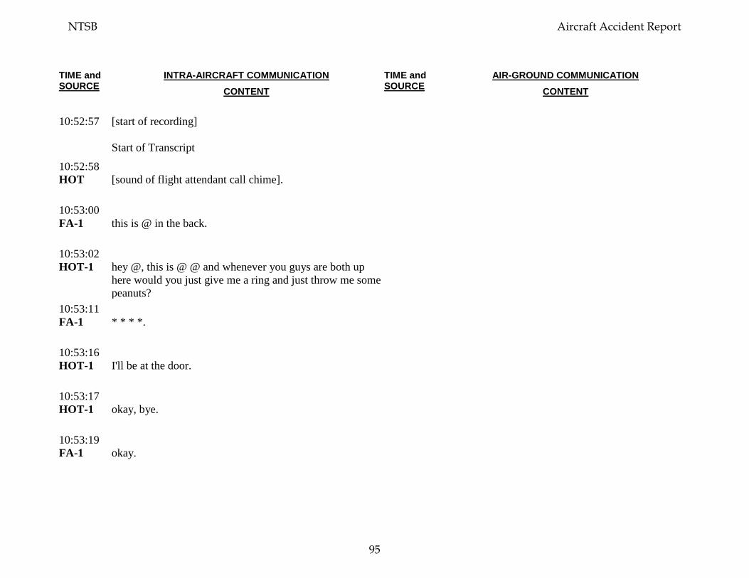
TIME and SOURCE
INTRA-AIRCRAFT COMMUNICATION CONTENT
TIME and SOURCE
AIR-GROUND COMMUNICATION CONTENT
10:52:57 [start of recording]
Start of Transcript
10:52:58 HOT [sound of flight attendant call chime].
10:53:00 FA-1 this is @ in the back.
10:53:02 HOT-1
hey @, this is @ @ and whenever you guys are both up here would you just give me a ring and just throw me some peanuts?
10:53:11 FA-1 * * * *.
10:53:16 HOT-1
I'll be at the door.
10:53:17 HOT-1
okay, bye.
10:53:19 FA-1 okay.
NTSB Aircraft Accident Report
95

TIME and SOURCE
INTRA-AIRCRAFT COMMUNICATION CONTENT
TIME and SOURCE
AIR-GROUND COMMUNICATION CONTENT
10:53:21 HOT-1
you’ve got it all.
10:53:23 HOT-1
the radios, everything. 'cause I'm gonna get some peanuts.
10:53:29 CTR (Southwest thirteen eighty) amend altitude maintain
flight level two two zero. 10:53:34 RDO-2
stop now at two two zero Southwest thirteen.
10:53:44 HOT-2
hey hello.
10:53:44 FA-1 hey, we're ready.
10:53:45 HOT-2
okay.
10:53:46 FA-1 okay.
10:53:47 HOT-2
they're ready.
NTSB Aircraft Accident Report
96
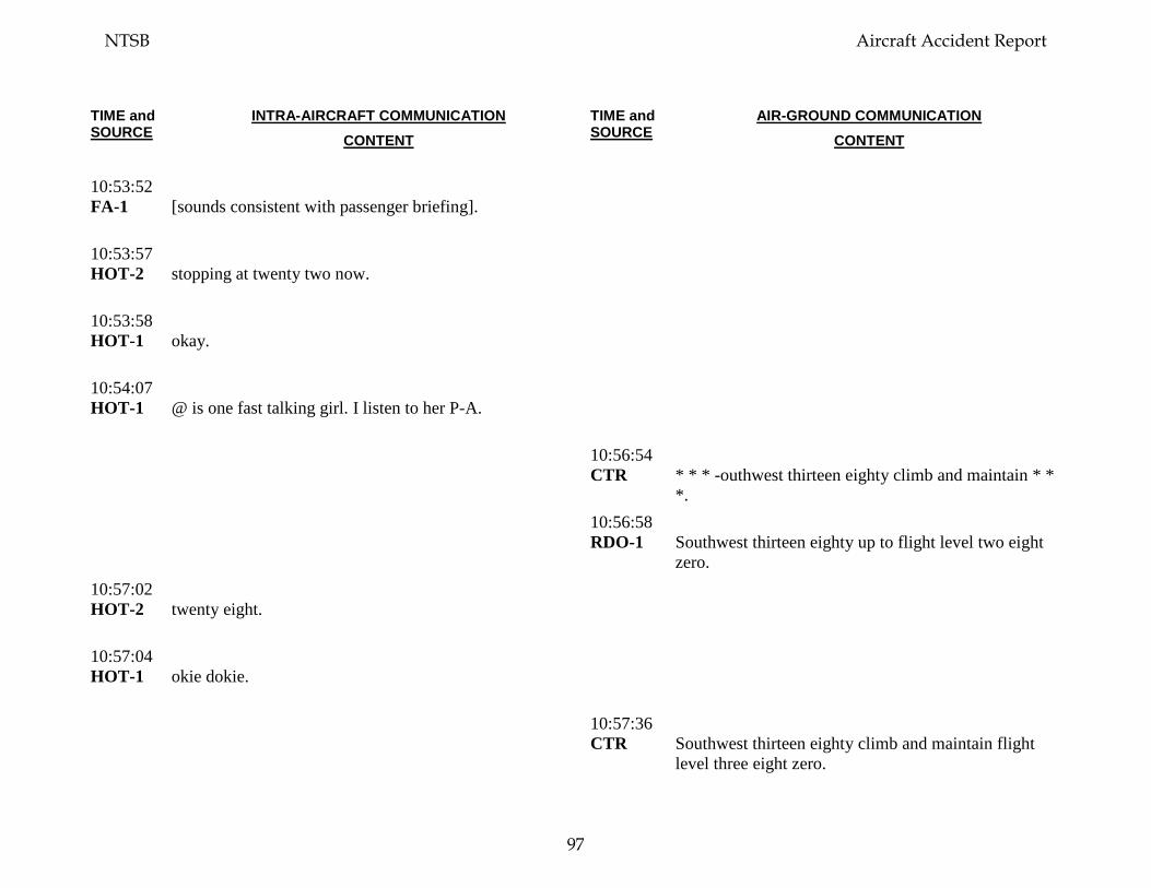
TIME and SOURCE
INTRA-AIRCRAFT COMMUNICATION CONTENT
TIME and SOURCE
AIR-GROUND COMMUNICATION CONTENT
10:53:52 FA-1 [sounds consistent with passenger briefing].
10:53:57 HOT-2
stopping at twenty two now.
10:53:58 HOT-1
okay.
10:54:07 HOT-1
@ is one fast talking girl. I listen to her P-A.
10:56:54 CTR * * * -outhwest thirteen eighty climb and maintain * *
*. 10:56:58 RDO-1
Southwest thirteen eighty up to flight level two eight zero.
10:57:02 HOT-2
twenty eight.
10:57:04 HOT-1
okie dokie.
10:57:36 CTR Southwest thirteen eighty climb and maintain flight
level three eight zero.
NTSB Aircraft Accident Report
97
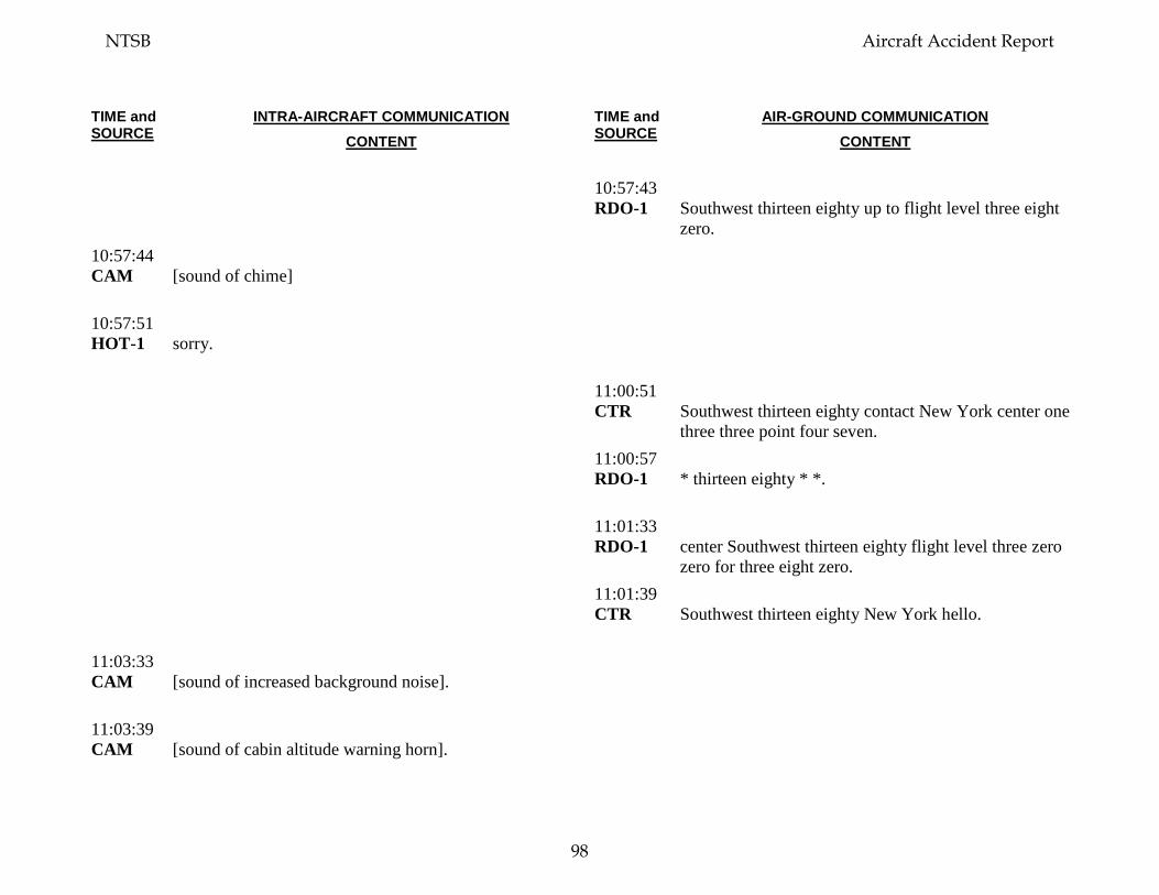
TIME and SOURCE
INTRA-AIRCRAFT COMMUNICATION CONTENT
TIME and SOURCE
AIR-GROUND COMMUNICATION CONTENT
10:57:43 RDO-1
Southwest thirteen eighty up to flight level three eight zero.
10:57:44 CAM [sound of chime]
10:57:51 HOT-1
sorry.
11:00:51 CTR Southwest thirteen eighty contact New York center one
three three point four seven. 11:00:57 RDO-1
* thirteen eighty * *.
11:01:33 RDO-1
center Southwest thirteen eighty flight level three zero zero for three eight zero.
11:01:39 CTR Southwest thirteen eighty New York hello.
11:03:33 CAM [sound of increased background noise].
11:03:39 CAM [sound of cabin altitude warning horn].
NTSB Aircraft Accident Report
98
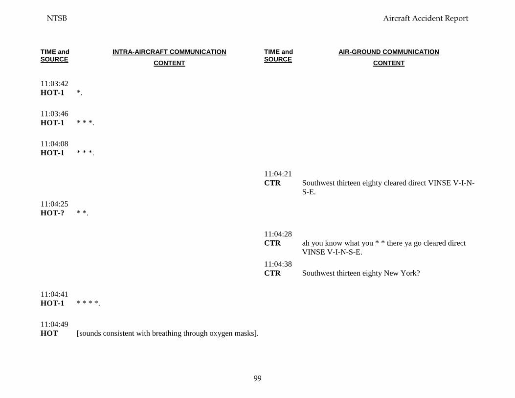
TIME and SOURCE
INTRA-AIRCRAFT COMMUNICATION CONTENT
TIME and SOURCE
AIR-GROUND COMMUNICATION CONTENT
11:03:42 HOT-1
*.
11:03:46 HOT-1
* * *.
11:04:08 HOT-1
* * *.
11:04:21 CTR Southwest thirteen eighty cleared direct VINSE V-I-N-
S-E. 11:04:25 HOT-?
* *.
11:04:28 CTR ah you know what you * * there ya go cleared direct
VINSE V-I-N-S-E. 11:04:38 CTR Southwest thirteen eighty New York?
11:04:41 HOT-1
* * * *.
11:04:49 HOT [sounds consistent with breathing through oxygen masks].
NTSB Aircraft Accident Report
99
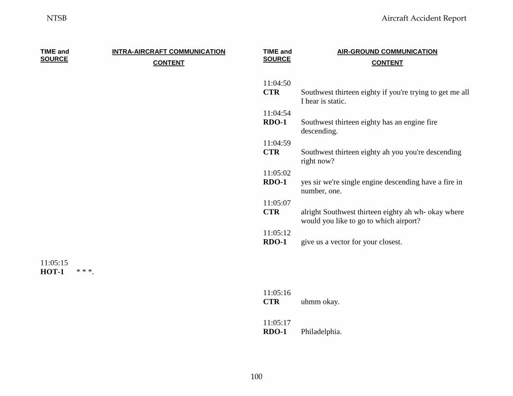
TIME and SOURCE
INTRA-AIRCRAFT COMMUNICATION CONTENT
TIME and SOURCE
AIR-GROUND COMMUNICATION CONTENT
11:04:50 CTR Southwest thirteen eighty if you're trying to get me all
I hear is static. 11:04:54 RDO-1
Southwest thirteen eighty has an engine fire descending.
11:04:59 CTR Southwest thirteen eighty ah you you're descending
right now? 11:05:02 RDO-1
yes sir we're single engine descending have a fire in number, one.
11:05:07 CTR alright Southwest thirteen eighty ah wh- okay where
would you like to go to which airport? 11:05:12 RDO-1
give us a vector for your closest.
11:05:15 HOT-1
* * *.
11:05:16 CTR uhmm okay.
11:05:17 RDO-1
Philadelphia.
NTSB Aircraft Accident Report
100
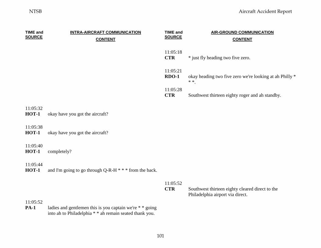
TIME and SOURCE
INTRA-AIRCRAFT COMMUNICATION CONTENT
TIME and SOURCE
AIR-GROUND COMMUNICATION CONTENT
11:05:18 CTR * just fly heading two five zero.
11:05:21 RDO-1
okay heading two five zero we're looking at ah Philly * * *.
11:05:28 CTR Southwest thirteen eighty roger and ah standby.
11:05:32 HOT-1
okay have you got the aircraft?
11:05:38 HOT-1
okay have you got the aircraft?
11:05:40 HOT-1
completely?
11:05:44 HOT-1
and I'm going to go through Q-R-H * * * from the back.
11:05:52 CTR Southwest thirteen eighty cleared direct to the
Philadelphia airport via direct. 11:05:52 PA-1 ladies and gentlemen this is you captain we're * * going
into ah to Philadelphia * * ah remain seated thank you.
NTSB Aircraft Accident Report
101
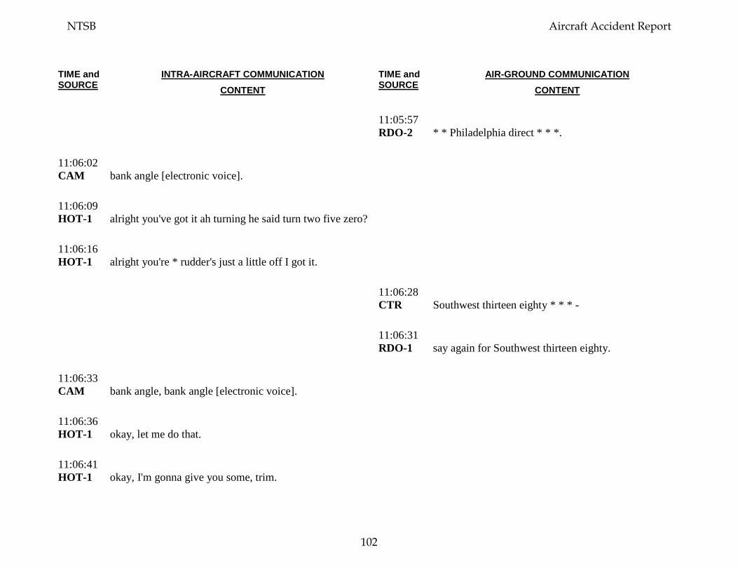
TIME and SOURCE
INTRA-AIRCRAFT COMMUNICATION CONTENT
TIME and SOURCE
AIR-GROUND COMMUNICATION CONTENT
11:05:57 RDO-2
* * Philadelphia direct * * *.
11:06:02 CAM bank angle [electronic voice].
11:06:09 HOT-1
alright you've got it ah turning he said turn two five zero?
11:06:16 HOT-1
alright you're * rudder's just a little off I got it.
11:06:28 CTR Southwest thirteen eighty * * * -
11:06:31 RDO-1
say again for Southwest thirteen eighty.
11:06:33 CAM bank angle, bank angle [electronic voice].
11:06:36 HOT-1
okay, let me do that.
11:06:41 HOT-1
okay, I'm gonna give you some, trim.
NTSB Aircraft Accident Report
102
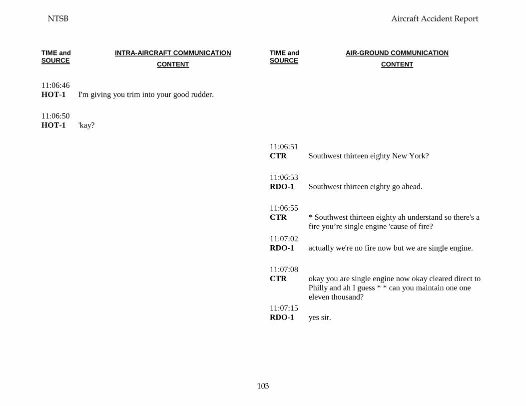
TIME and SOURCE
INTRA-AIRCRAFT COMMUNICATION CONTENT
TIME and SOURCE
AIR-GROUND COMMUNICATION CONTENT
11:06:46 HOT-1
I'm giving you trim into your good rudder.
11:06:50 HOT-1
'kay?
11:06:51 CTR
Southwest thirteen eighty New York?
11:06:53 RDO-1
Southwest thirteen eighty go ahead.
11:06:55 CTR
* Southwest thirteen eighty ah understand so there's a fire you’re single engine 'cause of fire?
11:07:02 RDO-1
actually we're no fire now but we are single engine.
11:07:08 CTR
okay you are single engine now okay cleared direct to Philly and ah I guess * * can you maintain one one eleven thousand?
11:07:15 RDO-1
yes sir.
NTSB Aircraft Accident Report
103
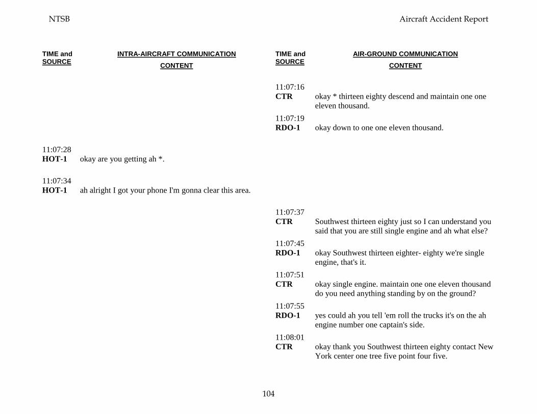
TIME and SOURCE
INTRA-AIRCRAFT COMMUNICATION CONTENT
TIME and SOURCE
AIR-GROUND COMMUNICATION CONTENT
11:07:16 CTR okay * thirteen eighty descend and maintain one one
eleven thousand. 11:07:19 RDO-1
okay down to one one eleven thousand.
11:07:28 HOT-1
okay are you getting ah *.
11:07:34 HOT-1
ah alright I got your phone I'm gonna clear this area.
11:07:37 CTR Southwest thirteen eighty just so I can understand you
said that you are still single engine and ah what else? 11:07:45 RDO-1
okay Southwest thirteen eighter- eighty we're single engine, that's it.
11:07:51 CTR okay single engine. maintain one one eleven thousand
do you need anything standing by on the ground? 11:07:55 RDO-1
yes could ah you tell 'em roll the trucks it's on the ah engine number one captain's side.
11:08:01 CTR okay thank you Southwest thirteen eighty contact New
York center one tree five point four five.
NTSB Aircraft Accident Report
104

TIME and SOURCE
INTRA-AIRCRAFT COMMUNICATION CONTENT
TIME and SOURCE
AIR-GROUND COMMUNICATION CONTENT
11:08:06 RDO-1
three five four five good day.
11:08:08 HOT-2
* * altimeter setting.
11:08:11 HOT-1
I'll get it.
11:08:12 RDO-1
center Southwest thirteen eighty declaring an emergency going through seventeen thousand need your local altimeter.
11:08:18 RDO-1
* altimeter?
11:08:19 CTR
ah South- thirteen eighty ah New York the ah Baltimore altimeter is ah two niner eight zero and you’re descending to one one thousand?
11:08:27 RDO-1
goin' down to one one thousand two nine eight zero?
11:08:31 CTR
Southwest thirteen eighty, thank you.
NTSB Aircraft Accident Report
105
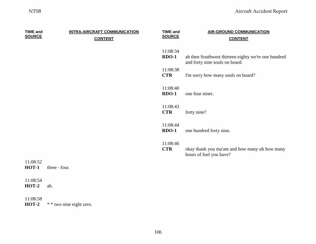
TIME and SOURCE
INTRA-AIRCRAFT COMMUNICATION CONTENT
TIME and SOURCE
AIR-GROUND COMMUNICATION CONTENT
11:08:34 RDO-1
ah then Southwest thirteen eighty we're one hundred and forty nine souls on board.
11:08:38 CTR
I'm sorry how many souls on board?
11:08:40 RDO-1
one four niner.
11:08:43 CTR
forty nine?
11:08:44 RDO-1
one hundred forty nine.
11:08:46 CTR
okay thank you ma'am and how many uh how many hours of fuel you have?
11:08:52 HOT-1
three - four.
11:08:54 HOT-2
ah.
11:08:58 HOT-2
* * two nine eight zero.
NTSB Aircraft Accident Report
106
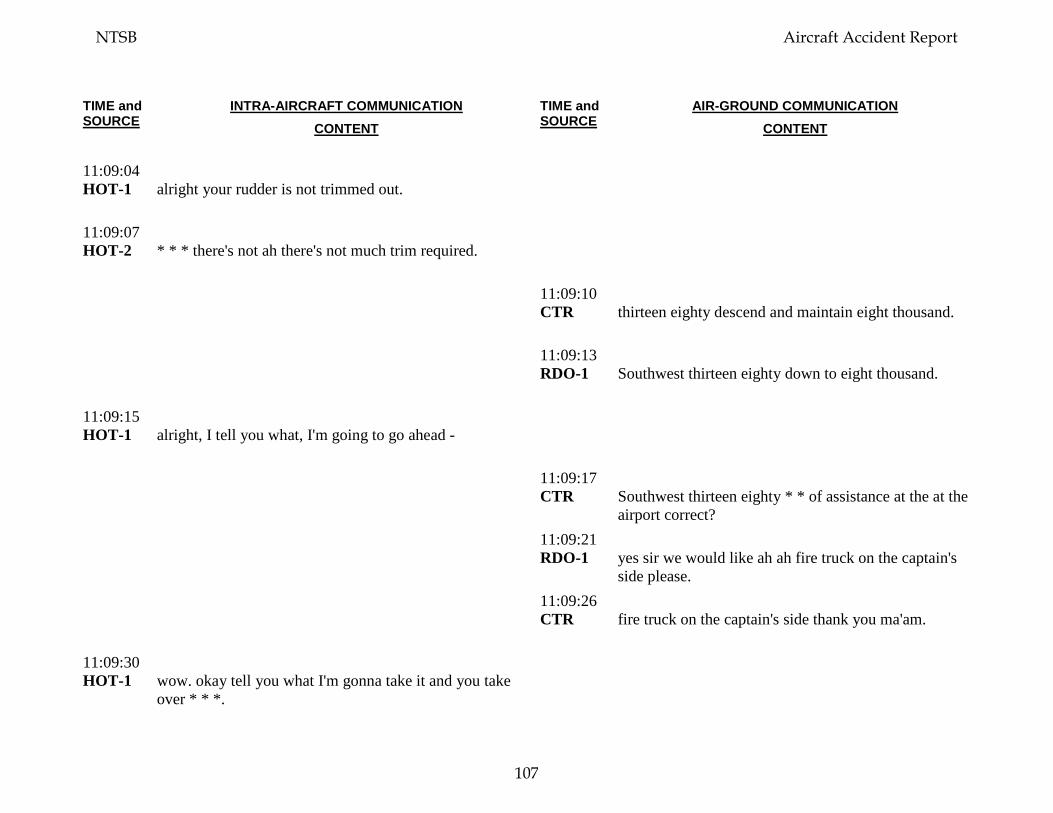
TIME and SOURCE
INTRA-AIRCRAFT COMMUNICATION CONTENT
TIME and SOURCE
AIR-GROUND COMMUNICATION CONTENT
11:09:04 HOT-1
alright your rudder is not trimmed out.
11:09:07 HOT-2
* * * there's not ah there's not much trim required.
11:09:10 CTR
thirteen eighty descend and maintain eight thousand.
11:09:13 RDO-1
Southwest thirteen eighty down to eight thousand.
11:09:15 HOT-1
alright, I tell you what, I'm going to go ahead -
11:09:17 CTR
Southwest thirteen eighty * * of assistance at the at the airport correct?
11:09:21 RDO-1
yes sir we would like ah ah fire truck on the captain's side please.
11:09:26 CTR
fire truck on the captain's side thank you ma'am.
11:09:30 HOT-1
wow. okay tell you what I'm gonna take it and you take over * * *.
NTSB Aircraft Accident Report
107
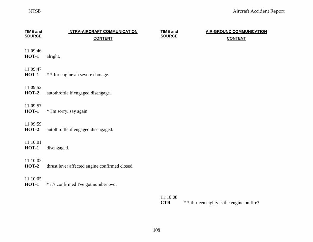
TIME and SOURCE
INTRA-AIRCRAFT COMMUNICATION CONTENT
TIME and SOURCE
AIR-GROUND COMMUNICATION CONTENT
11:09:46 HOT-1
alright.
11:09:47 HOT-1
* * for engine ah severe damage.
11:09:52 HOT-2
autothrottle if engaged disengage.
11:09:57 HOT-1
* I'm sorry. say again.
11:09:59 HOT-2
autothrottle if engaged disengaged.
11:10:01 HOT-1
disengaged.
11:10:02 HOT-2
thrust lever affected engine confirmed closed.
11:10:05 HOT-1
* it's confirmed I've got number two.
11:10:08 CTR
* * thirteen eighty is the engine on fire?
NTSB Aircraft Accident Report
108
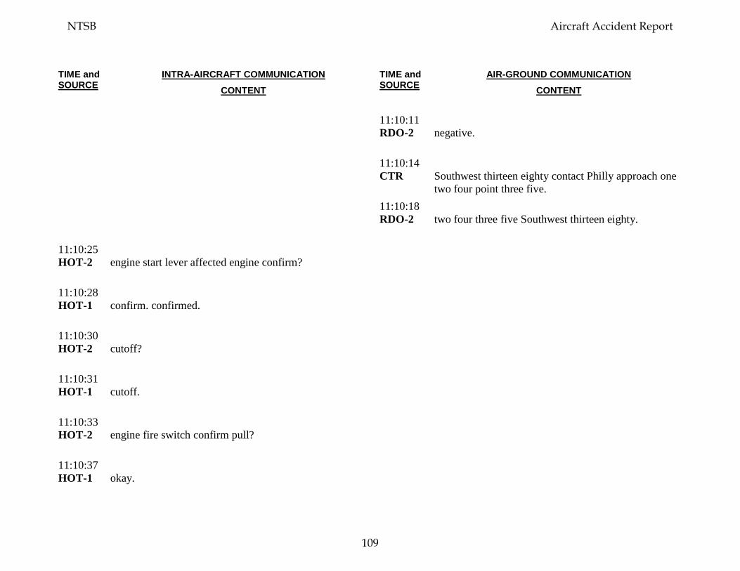
TIME and SOURCE
INTRA-AIRCRAFT COMMUNICATION CONTENT
TIME and SOURCE
AIR-GROUND COMMUNICATION CONTENT
11:10:11 RDO-2
negative.
11:10:14 CTR
Southwest thirteen eighty contact Philly approach one two four point three five.
11:10:18 RDO-2
two four three five Southwest thirteen eighty.
11:10:25 HOT-2
engine start lever affected engine confirm?
11:10:28 HOT-1
confirm. confirmed.
11:10:30 HOT-2
cutoff?
11:10:31 HOT-1
cutoff.
11:10:33 HOT-2
engine fire switch confirm pull?
11:10:37 HOT-1
okay.
NTSB Aircraft Accident Report
109
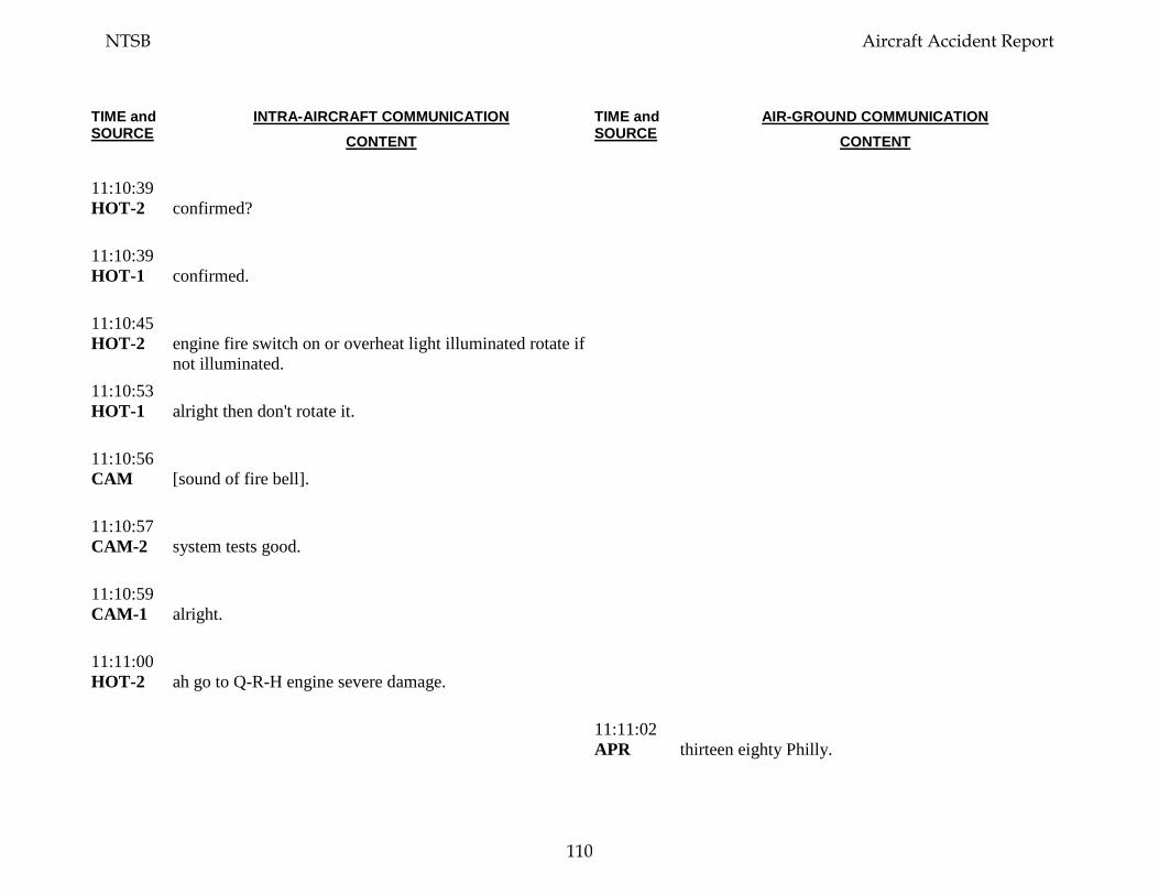
TIME and SOURCE
INTRA-AIRCRAFT COMMUNICATION CONTENT
TIME and SOURCE
AIR-GROUND COMMUNICATION CONTENT
11:10:39 HOT-2
confirmed?
11:10:39 HOT-1
confirmed.
11:10:45 HOT-2
engine fire switch on or overheat light illuminated rotate if not illuminated.
11:10:53 HOT-1
alright then don't rotate it.
11:10:56 CAM
[sound of fire bell].
11:10:57 CAM-2
system tests good.
11:10:59 CAM-1
alright.
11:11:00 HOT-2
ah go to Q-R-H engine severe damage.
11:11:02 APR
thirteen eighty Philly.
NTSB Aircraft Accident Report
110
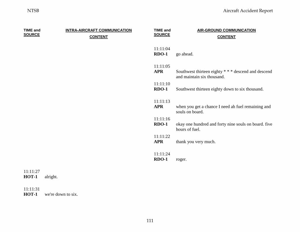
TIME and SOURCE
INTRA-AIRCRAFT COMMUNICATION CONTENT
TIME and SOURCE
AIR-GROUND COMMUNICATION CONTENT
11:11:04 RDO-1
go ahead.
11:11:05 APR
Southwest thirteen eighty * * * descend and descend and maintain six thousand.
11:11:10 RDO-1
Southwest thirteen eighty down to six thousand.
11:11:13 APR
when you get a chance I need ah fuel remaining and souls on board.
11:11:16 RDO-1
okay one hundred and forty nine souls on board. five hours of fuel.
11:11:22 APR
thank you very much.
11:11:24 RDO-1
roger.
11:11:27 HOT-1
alright.
11:11:31 HOT-1
we're down to six.
NTSB Aircraft Accident Report
111
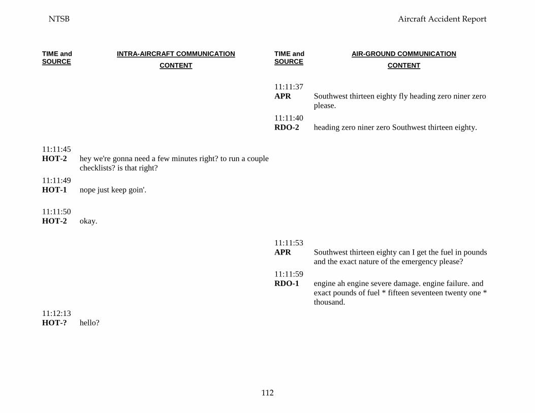
TIME and SOURCE
INTRA-AIRCRAFT COMMUNICATION CONTENT
TIME and SOURCE
AIR-GROUND COMMUNICATION CONTENT
11:11:37 APR
Southwest thirteen eighty fly heading zero niner zero please.
11:11:40 RDO-2
heading zero niner zero Southwest thirteen eighty.
11:11:45 HOT-2
hey we're gonna need a few minutes right? to run a couple checklists? is that right?
11:11:49 HOT-1
nope just keep goin'.
11:11:50 HOT-2
okay.
11:11:53 APR
Southwest thirteen eighty can I get the fuel in pounds and the exact nature of the emergency please?
11:11:59 RDO-1
engine ah engine severe damage. engine failure. and exact pounds of fuel * fifteen seventeen twenty one * thousand.
11:12:13 HOT-?
hello?
NTSB Aircraft Accident Report
112
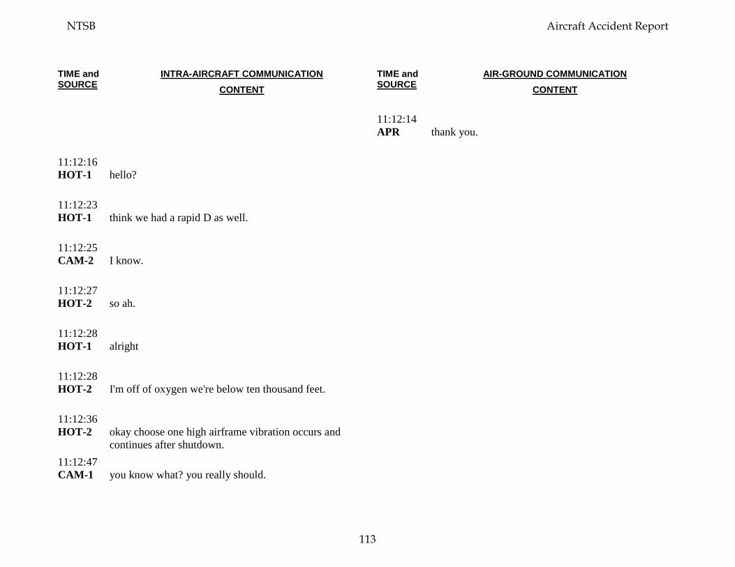
TIME and SOURCE
INTRA-AIRCRAFT COMMUNICATION CONTENT
TIME and SOURCE
AIR-GROUND COMMUNICATION CONTENT
11:12:14 APR
thank you.
11:12:16 HOT-1
hello?
11:12:23 HOT-1
think we had a rapid D as well.
11:12:25 CAM-2
I know.
11:12:27 HOT-2
so ah.
11:12:28 HOT-1
alright
11:12:28 HOT-2
I'm off of oxygen we're below ten thousand feet.
11:12:36 HOT-2
okay choose one high airframe vibration occurs and continues after shutdown.
11:12:47 CAM-1
you know what? you really should.
NTSB Aircraft Accident Report
113
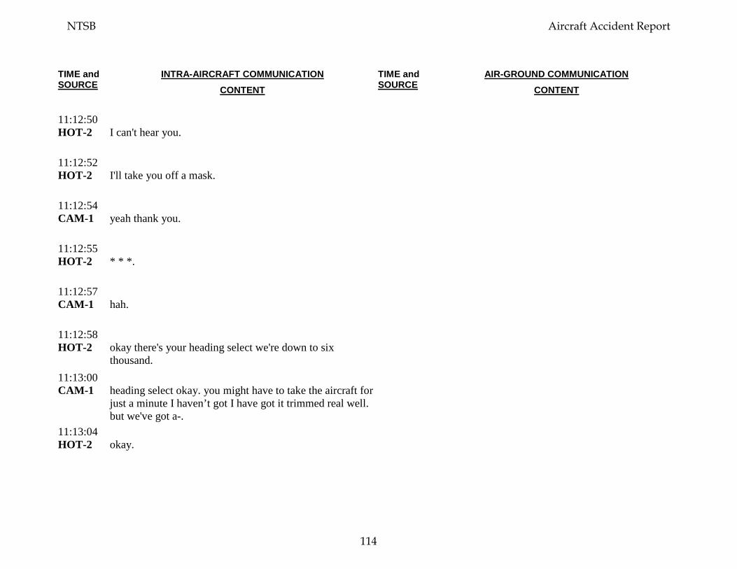
TIME and SOURCE
INTRA-AIRCRAFT COMMUNICATION CONTENT
TIME and SOURCE
AIR-GROUND COMMUNICATION CONTENT
11:12:50 HOT-2
I can't hear you.
11:12:52 HOT-2
I'll take you off a mask.
11:12:54 CAM-1
yeah thank you.
11:12:55 HOT-2
* * *.
11:12:57 CAM-1
hah.
11:12:58 HOT-2
okay there's your heading select we're down to six thousand.
11:13:00 CAM-1
heading select okay. you might have to take the aircraft for just a minute I haven’t got I have got it trimmed real well. but we've got a-.
11:13:04 HOT-2
okay.
NTSB Aircraft Accident Report
114
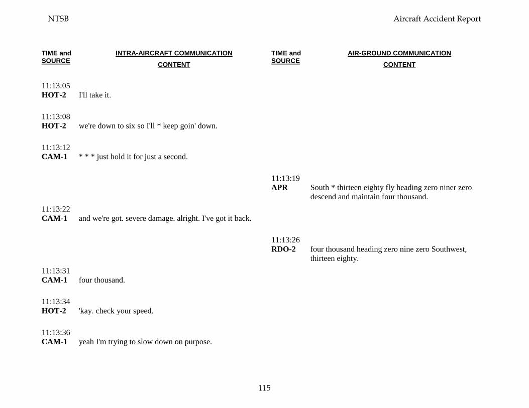
TIME and SOURCE
INTRA-AIRCRAFT COMMUNICATION CONTENT
TIME and SOURCE
AIR-GROUND COMMUNICATION CONTENT
11:13:05 HOT-2
I'll take it.
11:13:08 HOT-2
we're down to six so I'll * keep goin' down.
11:13:12 CAM-1
* * * just hold it for just a second.
11:13:19 APR
South * thirteen eighty fly heading zero niner zero descend and maintain four thousand.
11:13:22 CAM-1
and we're got. severe damage. alright. I've got it back.
11:13:26 RDO-2
four thousand heading zero nine zero Southwest, thirteen eighty.
11:13:31 CAM-1
four thousand.
11:13:34 HOT-2
'kay. check your speed.
11:13:36 CAM-1
yeah I'm trying to slow down on purpose.
NTSB Aircraft Accident Report
115
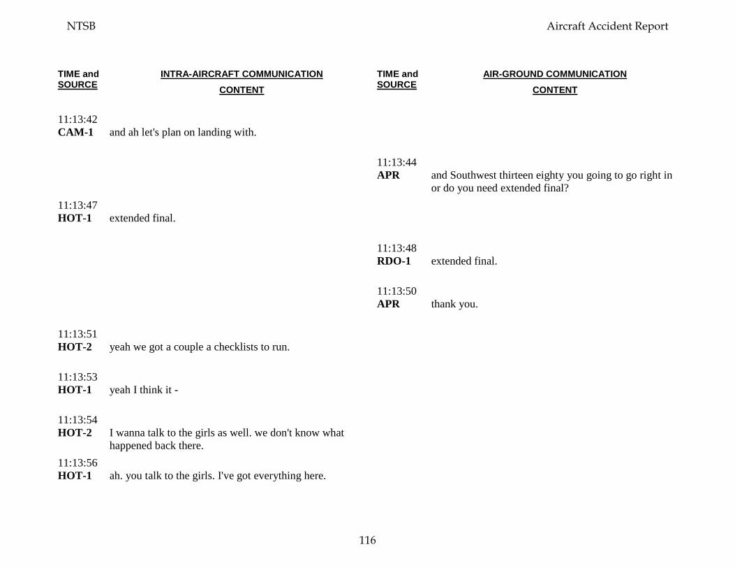
TIME and SOURCE
INTRA-AIRCRAFT COMMUNICATION CONTENT
TIME and SOURCE
AIR-GROUND COMMUNICATION CONTENT
11:13:42 CAM-1
and ah let's plan on landing with.
11:13:44 APR
and Southwest thirteen eighty you going to go right in or do you need extended final?
11:13:47 HOT-1
extended final.
11:13:48 RDO-1
extended final.
11:13:50 APR
thank you.
11:13:51 HOT-2
yeah we got a couple a checklists to run.
11:13:53 HOT-1
yeah I think it -
11:13:54 HOT-2
I wanna talk to the girls as well. we don't know what happened back there.
11:13:56 HOT-1
ah. you talk to the girls. I've got everything here.
NTSB Aircraft Accident Report
116
TIME and SOURCE
INTRA-AIRCRAFT COMMUNICATION CONTENT
TIME and SOURCE
AIR-GROUND COMMUNICATION CONTENT
11:14:00 HOT-2
okay.
11:14:02 APR
Southwest thirteen eighty contact approach now on one two eight point four.
11:14:07 RDO-1
Southwest thirteen eighty one two eight point four. we need a single channel no more channel switching.
11:14:14 APR
thirteen eighty you're on approach frequency one two eight point four. you're where you should be. maintain four thousand and ah do you need any further assistance from me? what type of final do you want? I heard short. or a long.
11:14:24 RDO-1
yeah, we're gonna need a long final.
11:14:24 INT-2
you guys there? hello?
11:14:26 APR
I'm gonna let you drive until you tell me you wanna turn base okay, so ah.
11:14:30 HOT-1
tell.
NTSB Aircraft Accident Report
117
TIME and SOURCE
INTRA-AIRCRAFT COMMUNICATION CONTENT
TIME and SOURCE
AIR-GROUND COMMUNICATION CONTENT
11:14:31 APR
at least a twenty five mile final, longer than that I'll have to do some coordination but that'll be fine we'll get that done for you.
11:14:36 HOT-2
I've got no reply from the back.
11:14:37 RDO-1
okay, twenty is good. and ah, we may need shorter here in a moment. tell me the runway we're settin' up for.
11:14:45 APR
set up for two -
11:14:47 RDO-1
say again.
11:14:49 HOT-1
no reply in the back?
11:14:50 APR
Southwest thirteen eighty you'll be landing two seven left, two seven left today. and ah you just let me know when you need to turn base ah I ah right now I only have one person in front of you which is a Southwest * I'm sure he'll pull off if you need to go.
NTSB Aircraft Accident Report
118
TIME and SOURCE
INTRA-AIRCRAFT COMMUNICATION CONTENT
TIME and SOURCE
AIR-GROUND COMMUNICATION CONTENT
11:15:00 CAM
[sound of chime].
11:15:01 HOT-1
okay, talk to the girls.
11:15:02 FA-2
we're goin' down.
11:15:04 INT-2
hello it's @.
11:15:04 FA-2
he we got * * a window open and somebody - is out the window.
11:15:09 INT-2
okay.
11:15:09 FA-2
we- we're almost landing.
11:15:10 INT-2
okay we wer' we're coming down is everyone else in their seats strapped in?
NTSB Aircraft Accident Report
119
TIME and SOURCE
INTRA-AIRCRAFT COMMUNICATION CONTENT
TIME and SOURCE
AIR-GROUND COMMUNICATION CONTENT
11:15:14 FA-2
yeah everyone still in their seats, we have people have been helpin' her get in I don't know what her condition is. but the window is completely out.
11:15:23 INT-2
okay we're gonna slow down.
11:15:24 HOT-2
slow down to two hundred ten knots right now.
11:15:26 FA-2
* * * (alrighty) are we almost there?
11:15:29 INT-2
yes we're gonna land as soon as we can.
11:15:29 RDO-1
* * * * we're gonna need to slow down a bit.
11:15:29 FA-2
okay, thank you.
11:15:33 FA-?
[unintelligible background voices].
NTSB Aircraft Accident Report
120
TIME and SOURCE
INTRA-AIRCRAFT COMMUNICATION CONTENT
TIME and SOURCE
AIR-GROUND COMMUNICATION CONTENT
11:15:33 FA-2
oh no.
11:15:34 APR
Southwest thirteen eighty, speed is your discretion. maintain ah at any altitude above three thousand feet and you let me know when you want to turn base.
11:15:38 HOT
[sound similar to chime].
11:15:42 RDO-1
alright down to three thousand.
11:15:45 FA-2
ladies and gentlemen please remain seated we’re * * back ladies and gentlemen we are almost landing.
11:15:47 HOT-2
okay we have somebody that's flown outside the *.
11:15:54 HOT-1
alright. severe damage. ah let's just ah. Let’s just a let’s do severe damage checklist and let’s get it turned in *.
11:16:02 HOT-2
okay isolation valve closed, pack affected side off, A-P-U bleed switch off choose, A-P-U available for start, start.
NTSB Aircraft Accident Report
121
TIME and SOURCE
INTRA-AIRCRAFT COMMUNICATION CONTENT
TIME and SOURCE
AIR-GROUND COMMUNICATION CONTENT
11:16:15 HOT-1
okay if we're going to do a flaps five landing (I believe).
11:16:18 HOT-2
flaps five.
11:16:19 HOT-1
because I don't know the controllability of this thing. gimme flaps one.
11:16:26 HOT-2
flaps one.
11:16:31 RDO-1
Southwest thirteen eight'd like to turn, start turning, inbound.
11:16:39 HOT-2
so we'll do a visual?
11:16:39 FA-2
everybody breathe and relax. everybody breathe we are almost landing.
11:16:44 FA-2
* * * * everybody breathe we are almost there.
NTSB Aircraft Accident Report
122
TIME and SOURCE
INTRA-AIRCRAFT COMMUNICATION CONTENT
TIME and SOURCE
AIR-GROUND COMMUNICATION CONTENT
11:16:47 APR
Southwest thirteen eighty turn ah just start turning southbound there there's Southwest seven three seven on a four mile final be turning southbound start looking for the airport it's off to your right and slightly behind you there. and ah altitude is your discretion use caution for the ah downtown area maintain ah advise you maintain at or above two thousand two hundred per ah the M-V-A.
11:16:50 FA-2
* *.
11:16:56 CAM
[sound of altitude alert tone].
11:17:04 RDO-1
okay could you have the ah medical meet us there on the runway as well we've got ah injured passengers.
11:17:12 APR
injured passengers okay and are you is your airplane physically on fire?
11:17:16 RDO-1
no it's not on fire but part of it's missing.
11:17:22 RDO-1
they said there’s a hole and ahm someone went out.
NTSB Aircraft Accident Report
123
TIME and SOURCE
INTRA-AIRCRAFT COMMUNICATION CONTENT
TIME and SOURCE
AIR-GROUND COMMUNICATION CONTENT
11:17:27 APR
ahm, I'm sorry you said there was a hole and somebody went out?
11:17:28 CAM-1
okay landing gear.
11:17:30 RDO-1
yes.
11:17:31 HOT-1
okay, landing gear.
11:17:32 APR
Southwest thirteen eighty it doesn't matter ah we'll work it out there so the airport's just off to your right report it in sight please.
11:17:33 CAM
[sound of chime].
11:17:35 CAM
[sound of altitude alert tone].
11:17:37 RDO-1
in sight. Southwest thirteen eighty airport's in sight.
NTSB Aircraft Accident Report
124
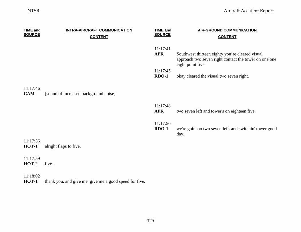
TIME and SOURCE
INTRA-AIRCRAFT COMMUNICATION CONTENT
TIME and SOURCE
AIR-GROUND COMMUNICATION CONTENT
11:17:41 APR
Southwest thirteen eighty you’re cleared visual approach two seven right contact the tower on one one eight point five.
11:17:45 RDO-1
okay cleared the visual two seven right.
11:17:46 CAM
[sound of increased background noise].
11:17:48 APR
two seven left and tower's on eighteen five.
11:17:50 RDO-1
we're goin' on two seven left. and switchin' tower good day.
11:17:56 HOT-1
alright flaps to five.
11:17:59 HOT-2
five.
11:18:02 HOT-1
thank you. and give me. give me a good speed for five.
NTSB Aircraft Accident Report
125
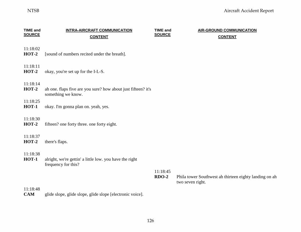
TIME and SOURCE
INTRA-AIRCRAFT COMMUNICATION CONTENT
TIME and SOURCE
AIR-GROUND COMMUNICATION CONTENT
11:18:02 HOT-2
[sound of numbers recited under the breath].
11:18:11 HOT-2
okay, you're set up for the I-L-S.
11:18:14 HOT-2
ah one. flaps five are you sure? how about just fifteen? it's something we know.
11:18:25 HOT-1
okay. I'm gonna plan on. yeah, yes.
11:18:30 HOT-2
fifteen? one forty three. one forty eight.
11:18:37 HOT-2
there's flaps.
11:18:38 HOT-1
alright, we're gettin' a little low. you have the right frequency for this?
11:18:45 RDO-2
Phila tower Southwest ah thirteen eighty landing on ah two seven right.
11:18:48 CAM
glide slope, glide slope, glide slope [electronic voice].
NTSB Aircraft Accident Report
126
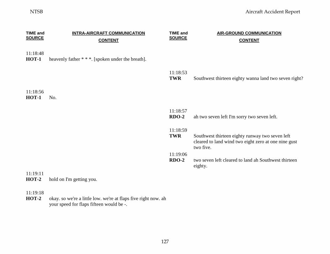
TIME and SOURCE
INTRA-AIRCRAFT COMMUNICATION CONTENT
TIME and SOURCE
AIR-GROUND COMMUNICATION CONTENT
11:18:48 HOT-1
heavenly father * * *. [spoken under the breath].
11:18:53 TWR
Southwest thirteen eighty wanna land two seven right?
11:18:56 HOT-1
No.
11:18:57 RDO-2
ah two seven left I'm sorry two seven left.
11:18:59 TWR
Southwest thirteen eighty runway two seven left cleared to land wind two eight zero at one nine gust two five.
11:19:06 RDO-2
two seven left cleared to land ah Southwest thirteen eighty.
11:19:11 HOT-2
hold on I'm getting you.
11:19:18 HOT-2
okay. so we're a little low. we're at flaps five right now. ah your speed for flaps fifteen would be -.
NTSB Aircraft Accident Report
127
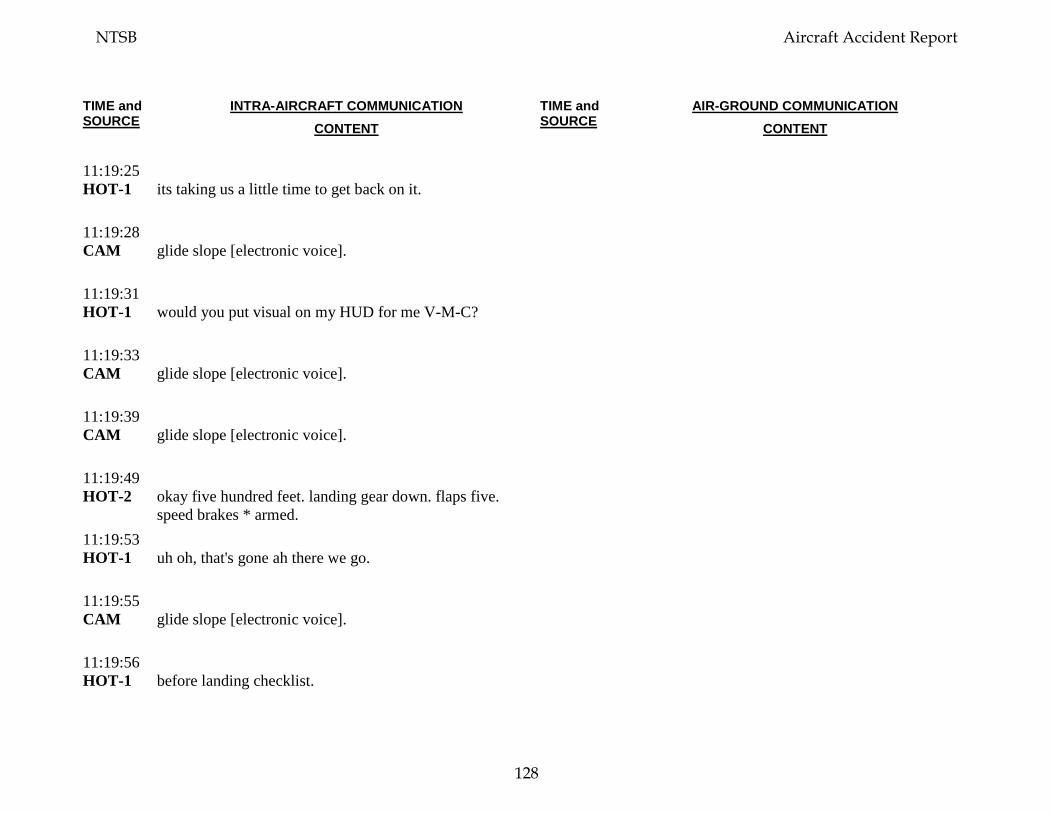
TIME and SOURCE
INTRA-AIRCRAFT COMMUNICATION CONTENT
TIME and SOURCE
AIR-GROUND COMMUNICATION CONTENT
11:19:25 HOT-1
its taking us a little time to get back on it.
11:19:28 CAM
glide slope [electronic voice].
11:19:31 HOT-1
would you put visual on my HUD for me V-M-C?
11:19:33 CAM
glide slope [electronic voice].
11:19:39 CAM
glide slope [electronic voice].
11:19:49 HOT-2
okay five hundred feet. landing gear down. flaps five. speed brakes * armed.
11:19:53 HOT-1
uh oh, that's gone ah there we go.
11:19:55 CAM
glide slope [electronic voice].
11:19:56 HOT-1
before landing checklist.
NTSB Aircraft Accident Report
128
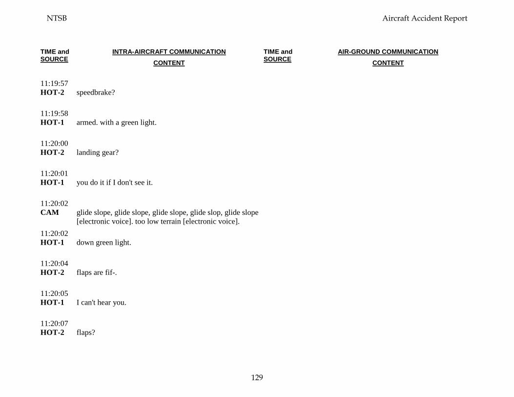
TIME and SOURCE
INTRA-AIRCRAFT COMMUNICATION CONTENT
TIME and SOURCE
AIR-GROUND COMMUNICATION CONTENT
11:19:57 HOT-2
speedbrake?
11:19:58 HOT-1
armed. with a green light.
11:20:00 HOT-2
landing gear?
11:20:01 HOT-1
you do it if I don't see it.
11:20:02 CAM
glide slope, glide slope, glide slope, glide slop, glide slope [electronic voice]. too low terrain [electronic voice].
11:20:02 HOT-1
down green light.
11:20:04 HOT-2
flaps are fif-.
11:20:05 HOT-1
I can't hear you.
11:20:07 HOT-2
flaps?
NTSB Aircraft Accident Report
129
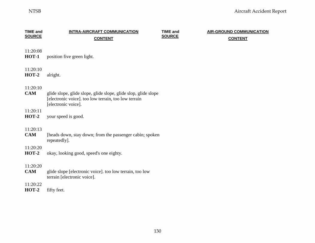
TIME and SOURCE
INTRA-AIRCRAFT COMMUNICATION CONTENT
TIME and SOURCE
AIR-GROUND COMMUNICATION CONTENT
11:20:08 HOT-1
position five green light.
11:20:10 HOT-2
alright.
11:20:10 CAM
glide slope, glide slope, glide slope, glide slop, glide slope [electronic voice]. too low terrain, too low terrain [electronic voice].
11:20:11 HOT-2
your speed is good.
11:20:13 CAM
[heads down, stay down; from the passenger cabin; spoken repeatedly].
11:20:20 HOT-2
okay, looking good, speed's one eighty.
11:20:20 CAM
glide slope [electronic voice]. too low terrain, too low terrain [electronic voice].
11:20:22 HOT-2
fifty feet.
NTSB Aircraft Accident Report
130
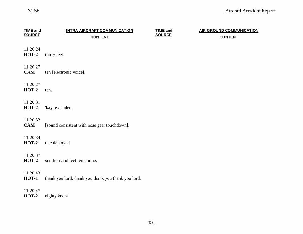
TIME and SOURCE
INTRA-AIRCRAFT COMMUNICATION CONTENT
TIME and SOURCE
AIR-GROUND COMMUNICATION CONTENT
11:20:24 HOT-2
thirty feet.
11:20:27 CAM
ten [electronic voice].
11:20:27 HOT-2
ten.
11:20:31 HOT-2
'kay, extended.
11:20:32 CAM
[sound consistent with nose gear touchdown].
11:20:34 HOT-2
one deployed.
11:20:37 HOT-2
six thousand feet remaining.
11:20:43 HOT-1
thank you lord. thank you thank you thank you lord.
11:20:47 HOT-2
eighty knots.
NTSB Aircraft Accident Report
131
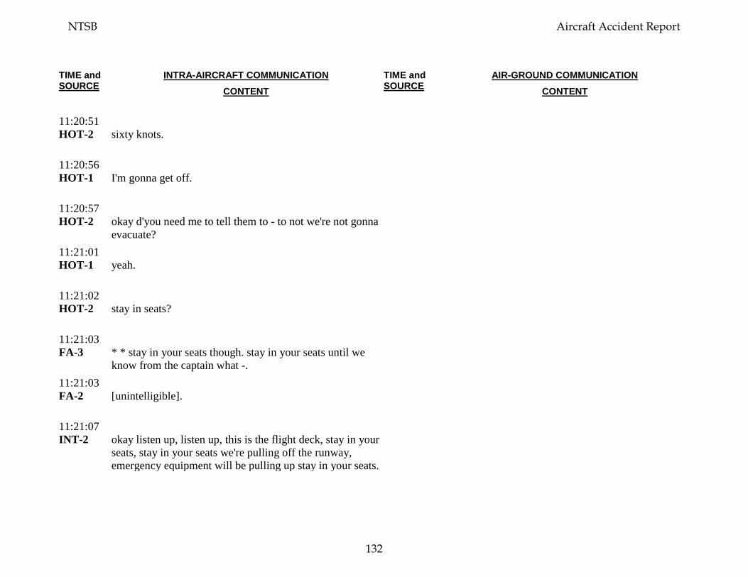
TIME and SOURCE
INTRA-AIRCRAFT COMMUNICATION CONTENT
TIME and SOURCE
AIR-GROUND COMMUNICATION CONTENT
11:20:51 HOT-2
sixty knots.
11:20:56 HOT-1
I'm gonna get off.
11:20:57 HOT-2
okay d'you need me to tell them to - to not we're not gonna evacuate?
11:21:01 HOT-1
yeah.
11:21:02 HOT-2
stay in seats?
11:21:03 FA-3
* * stay in your seats though. stay in your seats until we know from the captain what -.
11:21:03 FA-2
[unintelligible].
11:21:07 INT-2
okay listen up, listen up, this is the flight deck, stay in your seats, stay in your seats we're pulling off the runway, emergency equipment will be pulling up stay in your seats.
NTSB Aircraft Accident Report
132
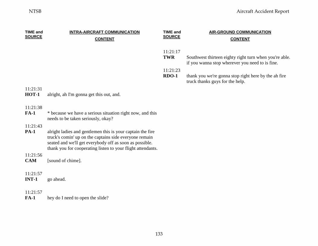
TIME and SOURCE
INTRA-AIRCRAFT COMMUNICATION CONTENT
TIME and SOURCE
AIR-GROUND COMMUNICATION CONTENT
11:21:17 TWR
Southwest thirteen eighty right turn when you're able. if you wanna stop wherever you need to is fine.
11:21:23 RDO-1
thank you we're gonna stop right here by the ah fire truck thanks guys for the help.
11:21:31 HOT-1
alright, ah I'm gonna get this out, and.
11:21:38 FA-1
* because we have a serious situation right now, and this needs to be taken seriously, okay?
11:21:43 PA-1
alright ladies and gentlemen this is your captain the fire truck's comin' up on the captains side everyone remain seated and we'll get everybody off as soon as possible. thank you for cooperating listen to your flight attendants.
11:21:56 CAM
[sound of chime].
11:21:57 INT-1
go ahead.
11:21:57 FA-1
hey do I need to open the slide?
NTSB Aircraft Accident Report
133
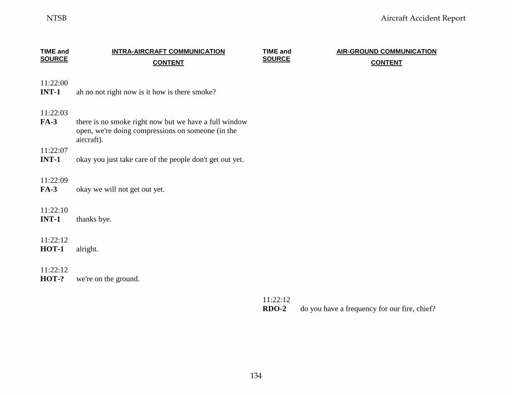
TIME and SOURCE
INTRA-AIRCRAFT COMMUNICATION CONTENT
TIME and SOURCE
AIR-GROUND COMMUNICATION CONTENT
11:22:00 INT-1
ah no not right now is it how is there smoke?
11:22:03 FA-3
there is no smoke right now but we have a full window open, we're doing compressions on someone (in the aircraft).
11:22:07 INT-1
okay you just take care of the people don't get out yet.
11:22:09 FA-3
okay we will not get out yet.
11:22:10 INT-1
thanks bye.
11:22:12 HOT-1
alright.
11:22:12 HOT-?
we're on the ground.
11:22:12 RDO-2
do you have a frequency for our fire, chief?
NTSB Aircraft Accident Report
134

TIME and SOURCE
INTRA-AIRCRAFT COMMUNICATION CONTENT
TIME and SOURCE
AIR-GROUND COMMUNICATION CONTENT
11:22:15 TWR
Southwest thirteen eighty if go over to one three five point one they'll.
11:22:19 HOT-1
what, sorry, sorry.
11:22:21 HOT-2
one three five point one.
11:22:24 HOT-1
one three five, one.
11:22:26 RDO-1
and fire truck this is captain from seven seven two.
11:22:33 TWR
fire truck twenty one that's the captain there go ahead.
11:22:35 RDO-1
yes sir I believe captains side is where we had the damage, and that's the engine that went out.
11:22:41 ARFF-1
ah yeah we we’re, we’re examining damage now check for a heat source ah is there any injuries inside the aircraft itself w- also we had no signs of any smoke or fire from the outside right now.
NTSB Aircraft Accident Report
135
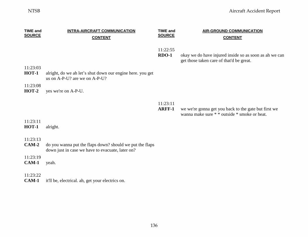
TIME and SOURCE
INTRA-AIRCRAFT COMMUNICATION CONTENT
TIME and SOURCE
AIR-GROUND COMMUNICATION CONTENT
11:22:55 RDO-1
okay we do have injured inside so as soon as ah we can get those taken care of that'd be great.
11:23:03 HOT-1
alright, do we ah let’s shut down our engine here. you get us on A-P-U? are we on A-P-U?
11:23:08 HOT-2
yes we're on A-P-U.
11:23:11 ARFF-1
we we're gonna get you back to the gate but first we wanna make sure * * outside * smoke or heat.
11:23:11 HOT-1
alright.
11:23:13 CAM-2
do you wanna put the flaps down? should we put the flaps down just in case we have to evacuate, later on?
11:23:19 CAM-1
yeah.
11:23:22 CAM-1
it'll be, electrical. ah, get your electrics on.
NTSB Aircraft Accident Report
136
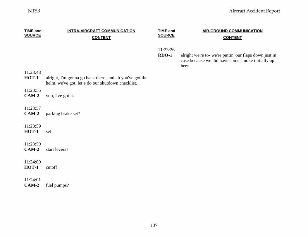
TIME and SOURCE
INTRA-AIRCRAFT COMMUNICATION CONTENT
TIME and SOURCE
AIR-GROUND COMMUNICATION CONTENT
11:23:26 RDO-1
alright we're to- we're puttin' our flaps down just in case because we did have some smoke initially up here.
11:23:48 HOT-1
alright, I'm gonna go back there, and ah you've got the helm. we've got, let’s do our shutdown checklist.
11:23:55 CAM-2
yup, I've got it.
11:23:57 CAM-2
parking brake set?
11:23:59 HOT-1
set
11:23:59 CAM-2
start levers?
11:24:00 HOT-1
cutoff
11:24:01 CAM-2
fuel pumps?
NTSB Aircraft Accident Report
137
TIME and SOURCE
INTRA-AIRCRAFT COMMUNICATION CONTENT
TIME and SOURCE
AIR-GROUND COMMUNICATION CONTENT
11:24:02 HOT-1
ahh.
11:24:05 HOT-1
one on.
11:24:06 CAM-2
window heat?
11:24:07 HOT-1
off.
11:24:07 CAM-2
probe heat?
11:24:08 HOT-1
off.
11:24:08 CAM-2
anti ice?
11:24:09 HOT-1
off.
11:24:10 CAM-2
hydraulic pumps?
NTSB Aircraft Accident Report
138
TIME and SOURCE
INTRA-AIRCRAFT COMMUNICATION CONTENT
TIME and SOURCE
AIR-GROUND COMMUNICATION CONTENT
11:24:10 HOT-1
electrics, we were using 'em.
11:24:12 CAM-2
'kay it's it's done.
11:24:13 ARFF -1
foxtrot twenty one ARFF command to pilot seven thirty seven, Southwest.
11:24:15 CAM-1
*. off.
11:24:19 HOT-2
start switches?
11:24:21 HOT-1
eh, off.
11:24:23 HOT-2
oil quantity?
11:24:24 HOT-1
is ahm, seventy three.
11:24:27 HOT-2
hydraulic quantity?
NTSB Aircraft Accident Report
139
TIME and SOURCE
INTRA-AIRCRAFT COMMUNICATION CONTENT
TIME and SOURCE
AIR-GROUND COMMUNICATION CONTENT
11:24:28 HOT-1
is ah.
11:24:29 ARFF -1
Philly tower. foxtrot twenty one.
11:24:31 HOT-2
radar?
11:24:31 TWR
twenty one *.
11:24:32 HOT-1
radar is off * *.
11:24:34 ARFF -1
can we talk to the pilot again?
11:24:35 CAM-2
transponder?
11:24:39 CAM-1
alright I'm just gonna check in back.
11:24:39 RDO-2
go ahead for southwest ah thirteen eighty.
NTSB Aircraft Accident Report
140
TIME and SOURCE
INTRA-AIRCRAFT COMMUNICATION CONTENT
TIME and SOURCE
AIR-GROUND COMMUNICATION CONTENT
11:24:43 RDO-2
Southwest thirteen eighty is up on thirty five one.
11:24:49 CAM-1
[sounds of captain in cabin briefing passengers and in-flight crew on job well done and status of the deplaning]. [sound of clapping].
11:24:51 TWR
foxtrot twenty one that’s the pilot there go ahead.
11:24:55 ARFF -1
alright how many injuries do you have on the aircraft?
11:24:57 RDO-2
we're trying to ah, were trying to figure it out right now. standby.
11:25:12 HOT-2
@ @? Alright.
11:25:18 OPS-1
* * to bring them out?
11:25:20 ARFF-1
Philly ARFF command we're gonna have busses come over for ya, and were gonna deplane and ah have some paramedics come on and take a look at the patients.
NTSB Aircraft Accident Report
141
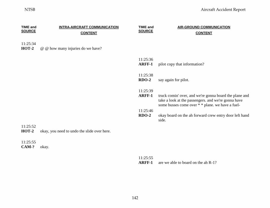
TIME and SOURCE
INTRA-AIRCRAFT COMMUNICATION CONTENT
TIME and SOURCE
AIR-GROUND COMMUNICATION CONTENT
11:25:34 HOT-2
@ @ how many injuries do we have?
11:25:36 ARFF-1
pilot copy that information?
11:25:38 RDO-2
say again for pilot.
11:25:39 ARFF-1
truck comin' over, and we're gonna board the plane and take a look at the passengers. and we're gonna have some busses come over * * plane. we have a fuel-
11:25:46 RDO-2
okay board on the ah forward crew entry door left hand side.
11:25:52 HOT-2
okay, you need to undo the slide over here.
11:25:55 CAM-?
okay.
11:25:55 ARFF-1
are we able to board on the ah R-1?
NTSB Aircraft Accident Report
142
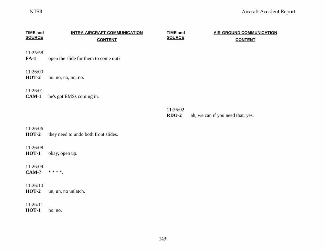
TIME and SOURCE
INTRA-AIRCRAFT COMMUNICATION CONTENT
TIME and SOURCE
AIR-GROUND COMMUNICATION CONTENT
11:25:58 FA-1
open the slide for them to come out?
11:26:00 HOT-2
no. no, no, no, no.
11:26:01 CAM-1
he's got EMSs coming in.
11:26:02 RDO-2
ah, we can if you need that, yes.
11:26:06 HOT-2
they need to undo both front slides.
11:26:08 HOT-1
okay, open up.
11:26:09 CAM-?
* * * *.
11:26:10 HOT-2
un, un, no unlatch.
11:26:11 HOT-1
no, no.
NTSB Aircraft Accident Report
143
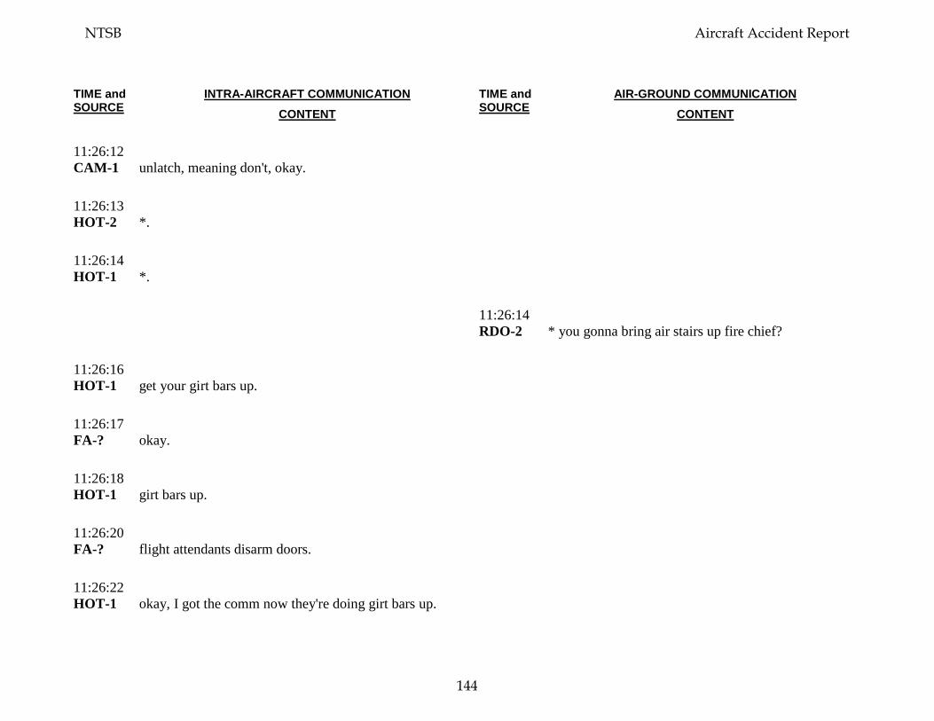
TIME and SOURCE
INTRA-AIRCRAFT COMMUNICATION CONTENT
TIME and SOURCE
AIR-GROUND COMMUNICATION CONTENT
11:26:12 CAM-1
unlatch, meaning don't, okay.
11:26:13 HOT-2
*.
11:26:14 HOT-1
*.
11:26:14 RDO-2
* you gonna bring air stairs up fire chief?
11:26:16 HOT-1
get your girt bars up.
11:26:17 FA-?
okay.
11:26:18 HOT-1
girt bars up.
11:26:20 FA-?
flight attendants disarm doors.
11:26:22 HOT-1
okay, I got the comm now they're doing girt bars up.
NTSB Aircraft Accident Report
144
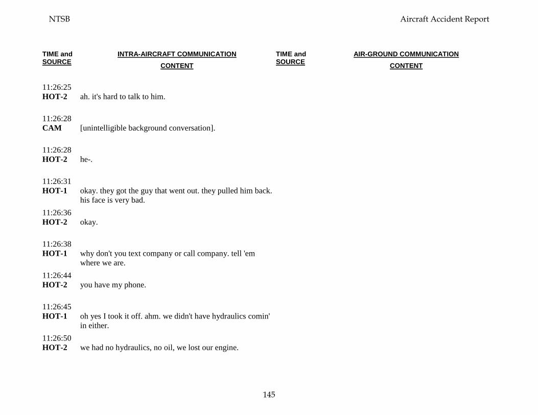
TIME and SOURCE
INTRA-AIRCRAFT COMMUNICATION CONTENT
TIME and SOURCE
AIR-GROUND COMMUNICATION CONTENT
11:26:25 HOT-2
ah. it's hard to talk to him.
11:26:28 CAM
[unintelligible background conversation].
11:26:28 HOT-2
he-.
11:26:31 HOT-1
okay. they got the guy that went out. they pulled him back. his face is very bad.
11:26:36 HOT-2
okay.
11:26:38 HOT-1
why don't you text company or call company. tell 'em where we are.
11:26:44 HOT-2
you have my phone.
11:26:45 HOT-1
oh yes I took it off. ahm. we didn't have hydraulics comin' in either.
11:26:50 HOT-2
we had no hydraulics, no oil, we lost our engine.
NTSB Aircraft Accident Report
145
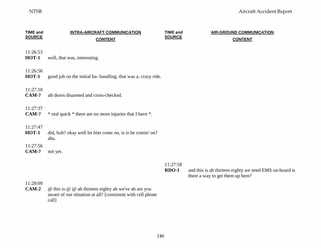
TIME and SOURCE
INTRA-AIRCRAFT COMMUNICATION CONTENT
TIME and SOURCE
AIR-GROUND COMMUNICATION CONTENT
11:26:53 HOT-1
well, that was, interesting.
11:26:56 HOT-1
good job on the initial ha- handling. that was a, crazy ride.
11:27:10 CAM-?
aft doors disarmed and cross-checked.
11:27:37 CAM-?
* real quick * there are no more injuries that I have *.
11:27:47 HOT-1
did, huh? okay well let him come on, is is he comin' on? aha.
11:27:56 CAM-?
not yet.
11:27:58 RDO-1
and this is ah thirteen eighty we need EMS on-board is there a way to get them up here?
11:28:09 CAM-2
@ this is @ @ ah thirteen eighty ah we've ah are you aware of our situation at all? [consistent with cell phone call]
NTSB Aircraft Accident Report
146
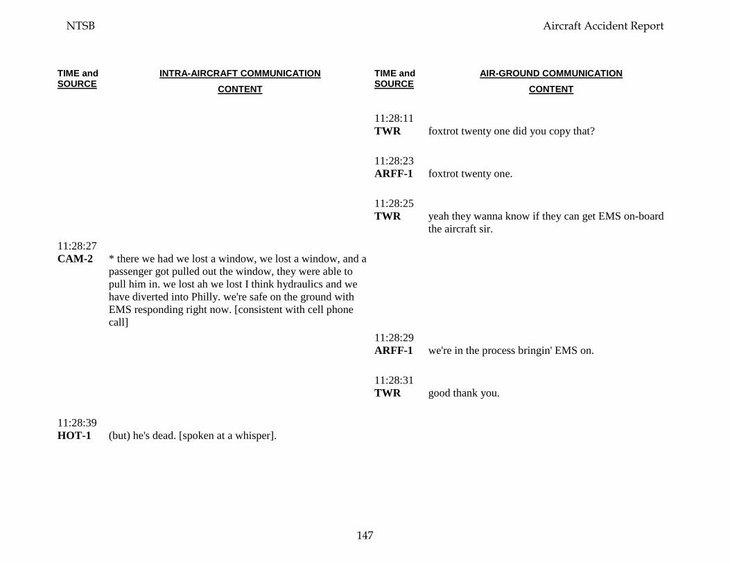
TIME and SOURCE
INTRA-AIRCRAFT COMMUNICATION CONTENT
TIME and SOURCE
AIR-GROUND COMMUNICATION CONTENT
11:28:11 TWR
foxtrot twenty one did you copy that?
11:28:23 ARFF-1
foxtrot twenty one.
11:28:25 TWR
yeah they wanna know if they can get EMS on-board the aircraft sir.
11:28:27 CAM-2
* there we had we lost a window, we lost a window, and a passenger got pulled out the window, they were able to pull him in. we lost ah we lost I think hydraulics and we have diverted into Philly. we're safe on the ground with EMS responding right now. [consistent with cell phone call]
11:28:29 ARFF-1
we're in the process bringin' EMS on.
11:28:31 TWR
good thank you.
11:28:39 HOT-1
(but) he's dead. [spoken at a whisper].
NTSB Aircraft Accident Report
147
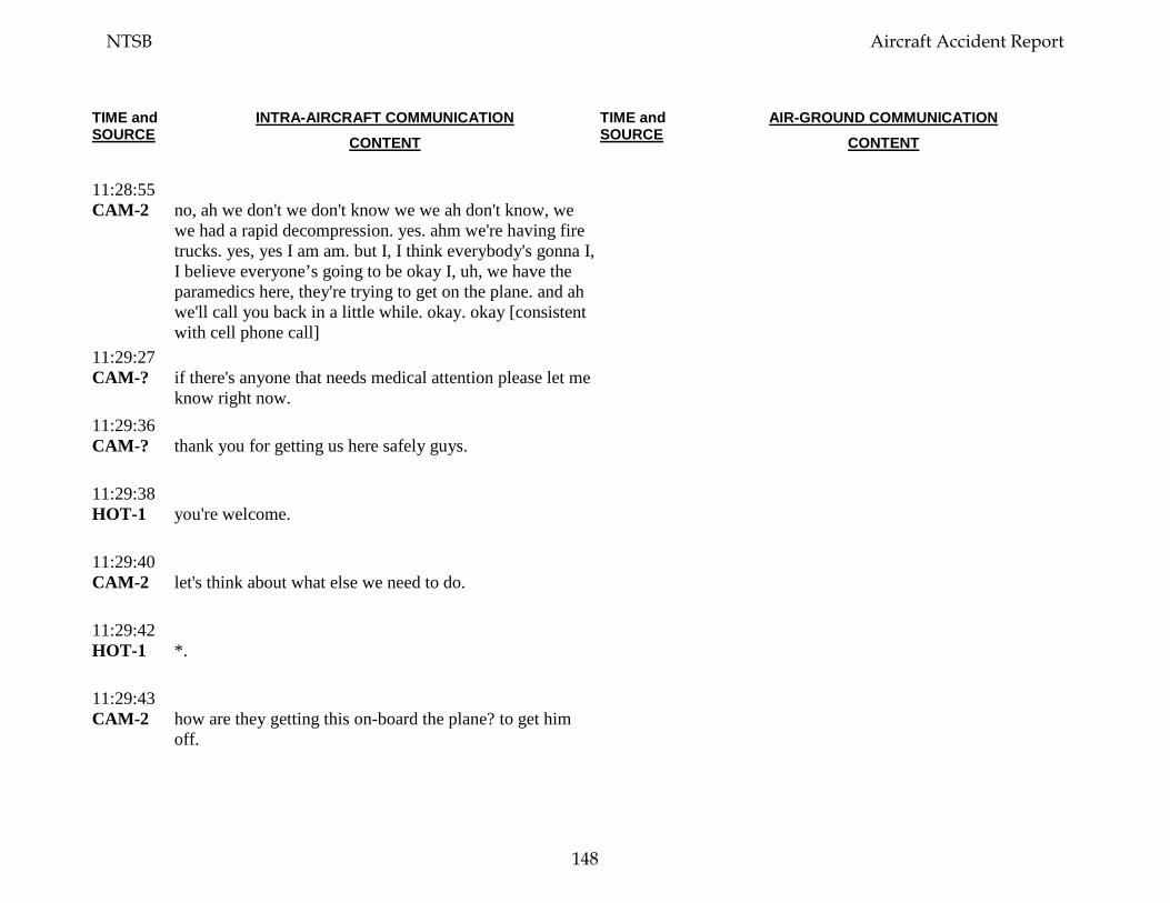
TIME and SOURCE
INTRA-AIRCRAFT COMMUNICATION CONTENT
TIME and SOURCE
AIR-GROUND COMMUNICATION CONTENT
11:28:55 CAM-2
no, ah we don't we don't know we we ah don't know, we we had a rapid decompression. yes. ahm we're having fire trucks. yes, yes I am am. but I, I think everybody's gonna I, I believe everyone’s going to be okay I, uh, we have the paramedics here, they're trying to get on the plane. and ah we'll call you back in a little while. okay. okay [consistent with cell phone call]
11:29:27 CAM-?
if there's anyone that needs medical attention please let me know right now.
11:29:36 CAM-?
thank you for getting us here safely guys.
11:29:38 HOT-1
you're welcome.
11:29:40 CAM-2
let's think about what else we need to do.
11:29:42 HOT-1
*.
11:29:43 CAM-2
how are they getting this on-board the plane? to get him off.
NTSB Aircraft Accident Report
148

TIME and SOURCE
INTRA-AIRCRAFT COMMUNICATION CONTENT
TIME and SOURCE
AIR-GROUND COMMUNICATION CONTENT
11:29:46 HOT-1
oh. they have a big ah.
11:29:50 CAM-1
* gonna just go see because, he said he was bringing around * * *.
11:29:58 CAM
[unintelligible conversation].
11:30:13 CAM-?
'kay they're coming with a (ladder).
11:30:20 CAM-?
(ladies and gentlemen) medical is coming now please clear the aisle, please clear the aisle. * * right through here. * * * where is he. * * * defibrillator * * * [unintelligible conversation].
11:30:38 ARFF-?
where is he?
11:30:53 CAM-2
it's just the one guy, that's hurt?
11:30:55 CAM-1
* lady.
NTSB Aircraft Accident Report
149
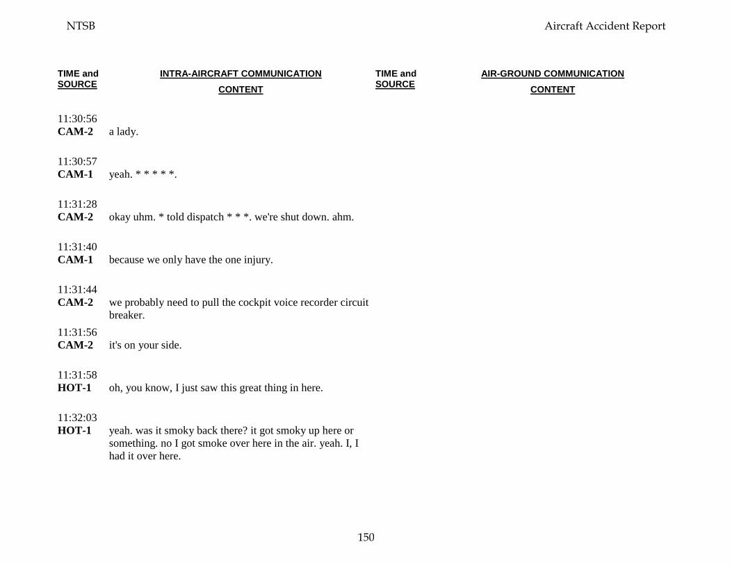
TIME and SOURCE
INTRA-AIRCRAFT COMMUNICATION CONTENT
TIME and SOURCE
AIR-GROUND COMMUNICATION CONTENT
11:30:56 CAM-2
a lady.
11:30:57 CAM-1
yeah. * * * * *.
11:31:28 CAM-2
okay uhm. * told dispatch * * *. we're shut down. ahm.
11:31:40 CAM-1
because we only have the one injury.
11:31:44 CAM-2
we probably need to pull the cockpit voice recorder circuit breaker.
11:31:56 CAM-2
it's on your side.
11:31:58 HOT-1
oh, you know, I just saw this great thing in here.
11:32:03 HOT-1
yeah. was it smoky back there? it got smoky up here or something. no I got smoke over here in the air. yeah. I, I had it over here.
NTSB Aircraft Accident Report
150
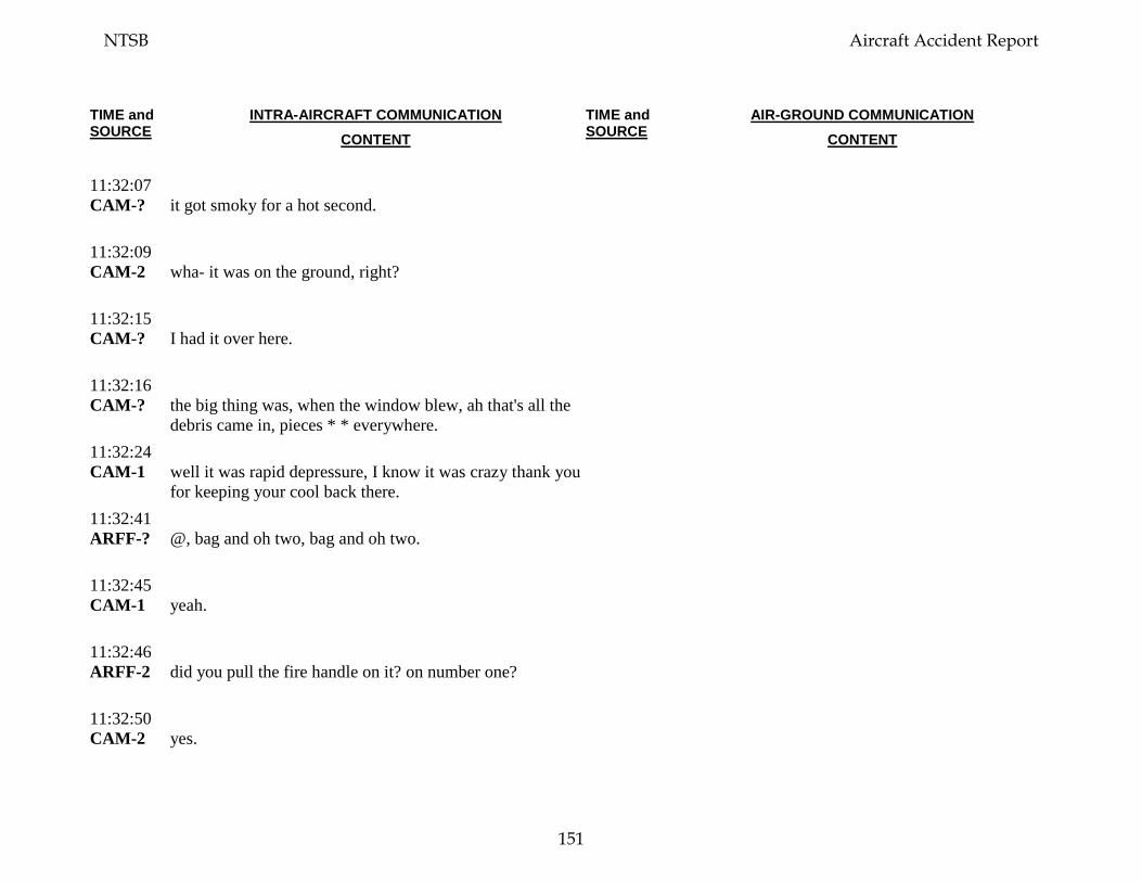
TIME and SOURCE
INTRA-AIRCRAFT COMMUNICATION CONTENT
TIME and SOURCE
AIR-GROUND COMMUNICATION CONTENT
11:32:07 CAM-?
it got smoky for a hot second.
11:32:09 CAM-2
wha- it was on the ground, right?
11:32:15 CAM-?
I had it over here.
11:32:16 CAM-?
the big thing was, when the window blew, ah that's all the debris came in, pieces * * everywhere.
11:32:24 CAM-1
well it was rapid depressure, I know it was crazy thank you for keeping your cool back there.
11:32:41 ARFF-?
@, bag and oh two, bag and oh two.
11:32:45 CAM-1
yeah.
11:32:46 ARFF-2
did you pull the fire handle on it? on number one?
11:32:50 CAM-2
yes.
NTSB Aircraft Accident Report
151
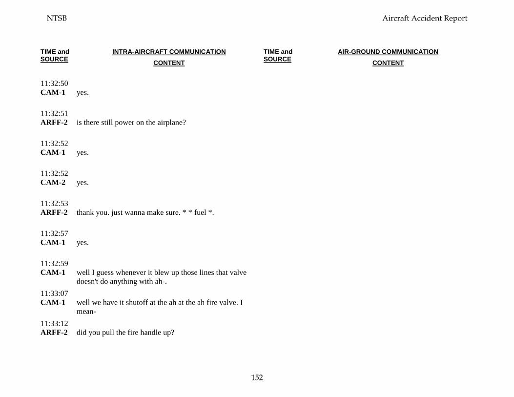
TIME and SOURCE
INTRA-AIRCRAFT COMMUNICATION CONTENT
TIME and SOURCE
AIR-GROUND COMMUNICATION CONTENT
11:32:50 CAM-1
yes.
11:32:51 ARFF-2
is there still power on the airplane?
11:32:52 CAM-1
yes.
11:32:52 CAM-2
yes.
11:32:53 ARFF-2
thank you. just wanna make sure. * * fuel *.
11:32:57 CAM-1
yes.
11:32:59 CAM-1
well I guess whenever it blew up those lines that valve doesn't do anything with ah-.
11:33:07 CAM-1
well we have it shutoff at the ah at the ah fire valve. I mean-
11:33:12 ARFF-2
did you pull the fire handle up?
NTSB Aircraft Accident Report
152
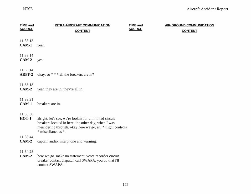
TIME and SOURCE
INTRA-AIRCRAFT COMMUNICATION CONTENT
TIME and SOURCE
AIR-GROUND COMMUNICATION CONTENT
11:33:13 CAM-1
yeah.
11:33:14 CAM-2
yes.
11:33:14 ARFF-2
okay, so * * * all the breakers are in?
11:33:18 CAM-2
yeah they are in. they're all in.
11:33:21 CAM-1
breakers are in.
11:33:36 HOT-1
alright, let's see, we're lookin' for uhm I had circuit breakers located in here, the other day, when I was meandering through. okay here we go, ah, * flight controls * miscellaneous *.
11:33:44 CAM-2
captain audio. interphone and warning.
11:34:28 CAM-2
here we go. make no statement. voice recorder circuit breaker contact dispatch call SWAPA. you do that I'll contact SWAPA.
NTSB Aircraft Accident Report
153
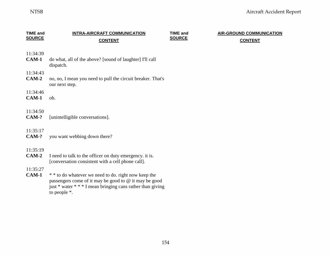
TIME and SOURCE
INTRA-AIRCRAFT COMMUNICATION CONTENT
TIME and SOURCE
AIR-GROUND COMMUNICATION CONTENT
11:34:39 CAM-1
do what, all of the above? [sound of laughter] I'll call dispatch.
11:34:43 CAM-2
no, no, I mean you need to pull the circuit breaker. That's our next step.
11:34:46 CAM-1
oh.
11:34:50 CAM-?
[unintelligible conversations].
11:35:17 CAM-?
you want webbing down there?
11:35:19 CAM-2
I need to talk to the officer on duty emergency. it is. [conversation consistent with a cell phone call].
11:35:27 CAM-1
* * to do whatever we need to do. right now keep the passengers come of it may be good to @ it may be good just * water * * * I mean bringing cans rather than giving to people *.
NTSB Aircraft Accident Report
154
TIME and SOURCE
INTRA-AIRCRAFT COMMUNICATION CONTENT
TIME and SOURCE
AIR-GROUND COMMUNICATION CONTENT
11:35:40 CAM-2
@ @ first officer [speaker spells out last name]. yes. thirteen eighty. [speaker recites a phone number]. yes we're okay. we're at Philly, I got another call, standby. [conversation consistent with a cell phone call].
11:35:45 CAM-?
* * *.
11:36:27 CAM-2
this is @. yeah what's up? okay, list- li- I need you, sir can you please listen to me? I have an emergency situation right now. I've diverted into Philadelphia. we have a possible passenger that's in very deep emergency ah medical condition right now. I don't have time to deal with scheduling. we'll, we'll call you. yeah. we'll ca- okay. bye-bye. [conversation consistent with a cell phone call].
11:36:27 CAM-1
@ @ @ hey I got a quick question. where is the cockpit recorder circuit breaker? * * * * lost * * pressurization * * * *. oh I found it, I found it. flight recorder. I'm gonna pull all three. * * * okay. I just pulled all three. * * yeah we will * * lost engine * [conversation consistent with a cell phone call].
11:36:31 CAM-?
* * blue bag * * blue bag * *.
NTSB Aircraft Accident Report
155
TIME and SOURCE
INTRA-AIRCRAFT COMMUNICATION CONTENT
TIME and SOURCE
AIR-GROUND COMMUNICATION CONTENT
11:36:41 CAM-?
yup * blue bag *.
11:36:51 CAM-?
* I don't know yet. yup. * * * to (help). * * * * *.
11:37:06 CAM-2
hello? are you there? is this SWAPA? okay I just had some * * * okay. uhm whadda, what do you need? ah a window blew out of our airplane. a rapid decompression. okay. [conversation consistent with a cell phone call].
11:37:38 CAM-2
did we get this, circuit breaker?
11:37:40 CAM-1
yeah.
11:38:02 CAM-?
[barely intelligible communication from ground or ARFF personnel].
11:38:03 HOT-1
so, I'm just wondering so I can tell the passengers. ahm, we're gonna wait here until we have everything secured and then get.
11:38:19 HOT-1
okay. okay. * tell 'em what's goin' on.
NTSB Aircraft Accident Report
156
TIME and SOURCE
INTRA-AIRCRAFT COMMUNICATION CONTENT
TIME and SOURCE
AIR-GROUND COMMUNICATION CONTENT
11:38:34 CAM-1
[barely audible sounds consistent with captain briefing passengers on status of the deplaning process].
11:39:46 CAM
[unintelligible background voices].
11:39:48 CAM-2
yes. hello? okay are you with SWAPA safety? ah. ahm, yes. now we had a window blow out and a passenger fly out the window. they caught her. yes a passenger was outside the airplane and they pulled her back in. @ @ [speaker spells out last name] eight @. na I'm the first officer she's busy. ah LaGuardia to Dallas, we're in Philadelphia. ah, uhm, thirty eight thousand? * * * * thirty eight we were at thirty eight and we had been for a while. ah, I don't but I'm guessing on the captain’s side, that's the engine we lost. we lost an engine and ha- and hydraulics. yes. yes. yes. ah I think that's right, yeah. ah no we had some quantity. yeah. yeah we had about. right now we have fifty six percent. * * female she's in really bad shape. she's in bad, bad shape. I would say that but I'm not a doctor. yeah. most I think maybe the top half. I don't know it’s very hard to get information. I don't know. [conversation consistent with a cell phone call].
11:42:14 CAM
[sound of siren].
NTSB Aircraft Accident Report
157
TIME and SOURCE
INTRA-AIRCRAFT COMMUNICATION CONTENT
TIME and SOURCE
AIR-GROUND COMMUNICATION CONTENT
11:42:59 CAM-2
did the engine blow up?
11:43:00 CAM-1
ah the forward, forward section here on.
11:43:14 CAM-2
okay, it loo- it looks like we lost a couple of the fan blades on, on, on, th- ah the ah the ah inlet. and the engine ah I thi- I hard to guess. is this recorded? okay ahm I think a fan blade ble- I think the engine blew up I think a fan blade pierced our window I think we had a rapid decompression because of that. that's what I think happened. [conversation consistent with a cell phone call].
11:43:19 CAM-1
forward section.
11:43:42 CAM-1
oh yeah.
11:43:46 CAM-2
we did do a high dive, yeah. a controlled high dive, yeah. [conversation consistent with a cell phone call].
11:43:55 CAM
[sound of clapping].
NTSB Aircraft Accident Report
158
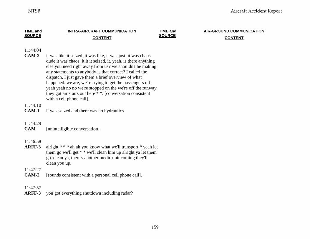
TIME and SOURCE
INTRA-AIRCRAFT COMMUNICATION CONTENT
TIME and SOURCE
AIR-GROUND COMMUNICATION CONTENT
11:44:04 CAM-2
it was like it seized. it was like, it was just. it was chaos dude it was chaos. it it it seized, it. yeah. is there anything else you need right away from us? we shouldn't be making any statements to anybody is that correct? I called the dispatch, I just gave them a brief overview of what happened. we are, we're trying to get the passengers off. yeah yeah no no we're stopped on the we're off the runway they got air stairs out here * *. [conversation consistent with a cell phone call].
11:44:10 CAM-1
it was seized and there was no hydraulics.
11:44:29 CAM
[unintelligible conversation].
11:46:58 ARFF-3
alright * * * ah ah you know what we'll transport * yeah let them go we'll get * * we'll clean him up alright ya let them go. clean ya, there's another medic unit coming they'll clean you up.
11:47:27 CAM-2
[sounds consistent with a personal cell phone call].
11:47:57 ARFF-3
you got everything shutdown including radar?
NTSB Aircraft Accident Report
159
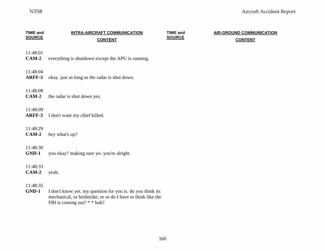
TIME and SOURCE
INTRA-AIRCRAFT COMMUNICATION CONTENT
TIME and SOURCE
AIR-GROUND COMMUNICATION CONTENT
11:48:01 CAM-2
everything is shutdown except the APU is running.
11:48:04 ARFF-3
okay. just as long as the radar is shut down.
11:48:08 CAM-2
the radar is shut down yes.
11:48:09 ARFF-3
I don't want my chief killed.
11:48:29 CAM-2
hey what's up?
11:48:30 GND-1
you okay? making sure yo- you're alright.
11:48:33 CAM-2
yeah.
11:48:35 GND-1
I don't know yet. my question for you is. do you think its mechanical, or birdstrike, or or do I have to think like the FBI is coming out? * * huh?
NTSB Aircraft Accident Report
160
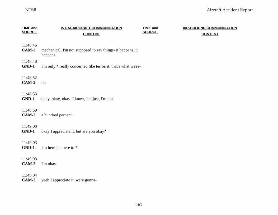
TIME and SOURCE
INTRA-AIRCRAFT COMMUNICATION CONTENT
TIME and SOURCE
AIR-GROUND COMMUNICATION CONTENT
11:48:46 CAM-2
mechanical, I'm not supposed to say things- it happens, it happens.
11:48:48 GND-1
I'm only * really concerned like terrorist, that's what we're-
11:48:52 CAM-2
no
11:48:53 GND-1
okay, okay, okay. I know, I'm just, I'm just.
11:48:59 CAM-2
a hundred percent.
11:49:00 GND-1
okay I appreciate it. but are you okay?
11:49:03 GND-1
I'm here I'm here to *.
11:49:03 CAM-2
I'm okay.
11:49:04 CAM-2
yeah I appreciate it. were gonna-
NTSB Aircraft Accident Report
161
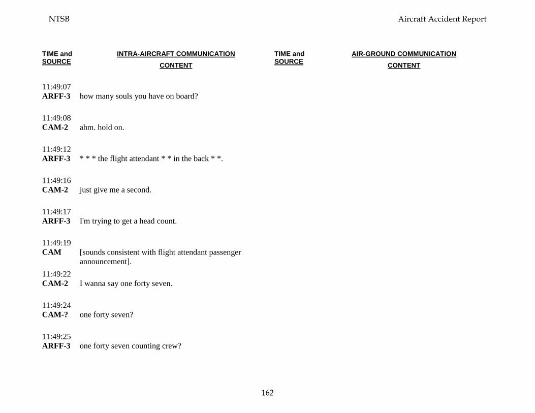
TIME and SOURCE
INTRA-AIRCRAFT COMMUNICATION CONTENT
TIME and SOURCE
AIR-GROUND COMMUNICATION CONTENT
11:49:07 ARFF-3
how many souls you have on board?
11:49:08 CAM-2
ahm. hold on.
11:49:12 ARFF-3
* * * the flight attendant * * in the back * *.
11:49:16 CAM-2
just give me a second.
11:49:17 ARFF-3
I'm trying to get a head count.
11:49:19 CAM
[sounds consistent with flight attendant passenger announcement].
11:49:22 CAM-2
I wanna say one forty seven.
11:49:24 CAM-?
one forty seven?
11:49:25 ARFF-3
one forty seven counting crew?
NTSB Aircraft Accident Report
162
TIME and SOURCE
INTRA-AIRCRAFT COMMUNICATION CONTENT
TIME and SOURCE
AIR-GROUND COMMUNICATION CONTENT
11:49:28 CAM-2
that's one forty two plus two that's one forty four plus five crew one forty nine total.
11:49:36 ARFF-3
one forty nine total?
11:49:36 CAM-2
one forty nine total souls on board.
11:49:36 CAM
foxtrot twenty one driver foxtrot twenty one.
11:49:39 ARFF-3
one forty nine, total.
11:49:41 CAM-2
total.
11:49:41 ARFF-3
okay and we just transported one so one's down so * * * you should have one forty eight on board.
11:49:46 CAM-2
okay.
11:49:47 CAM
[sound consistent with cell phone ringtone].
NTSB Aircraft Accident Report
163
TIME and SOURCE
INTRA-AIRCRAFT COMMUNICATION CONTENT
TIME and SOURCE
AIR-GROUND COMMUNICATION CONTENT
11:50:07 CAM
[unintelligible background conversations].
11:51:55 CAM
[sounds consistent with initiation of passenger deplaning activities].
11:53:14 CAM-?
okay I need about fifty people first.
11:57:02 CAM-1
clear the aisle's please clear the aisle we got something coming up clear the aisles.
11:57:21 CAM
[sounds consistent with passenger deplaning activities].
11:58:52 CAM-?
* * send out update to the chief * * update about * * * okay the deputy the chief * *.
11:59:02 CAM
[unintelligible background conversations].
12:16:14 CAM-1
alright * * APU * *.
12:16:25 CAM-2
we don't have any power so.
NTSB Aircraft Accident Report
164
TIME and SOURCE
INTRA-AIRCRAFT COMMUNICATION CONTENT
TIME and SOURCE
AIR-GROUND COMMUNICATION CONTENT
12:16:28 CAM-1
I mean just you know like this.
12:16:29 CAM-2
yeah.
12:16:30 CAM-?
first officer?
12:16:31 CAM-2
yes.
12:16:31 CAM-?
okay I have the deputy chief wants to talk to you. er the commissioner wants to talk to you. when you get a chance. as soon as * * * as soon as everybody’s off *.
12:16:40 CAM-2
oh okay.
12:16:51 CAM-1
* * * anything we don't need. alright. I'm gonna.
12:17:07 CAM-1
well @. good job.
NTSB Aircraft Accident Report
165
TIME and SOURCE
INTRA-AIRCRAFT COMMUNICATION CONTENT
TIME and SOURCE
AIR-GROUND COMMUNICATION CONTENT
12:17:11 CAM-2
good job to you.
12:17:11 CAM-1
I know you didn't have time to go through all of it but I could feel that it was just not in good condition is why-
12:17:17 CAM-2
and she wasn't in good condition.
12:17:19 CAM-1
is why I said give us a short one, we'll do checklists, you and I.
12:17:21 CAM-2
that's fine, I understand.
12:17:22 CAM-1
you and I between the two of us I knew we wouldn't land with, out the gear. you know what I mean?
12:17:26 CAM-2
yeah.
12:17:26 CAM-1
and so, I just thought, you know what we just need to. and the flaps five was my call not a checklist call because of the severe damage. and I could feel -
NTSB Aircraft Accident Report
166
TIME and SOURCE
INTRA-AIRCRAFT COMMUNICATION CONTENT
TIME and SOURCE
AIR-GROUND COMMUNICATION CONTENT
12:17:33 CAM-2
I understand we and we we didn't know what the damage was and there and actually to look at the leading edge look at the leading edge.
12:17:36 CAM-1
I know.
12:17:37 CAM-1
and no hydraulics.
12:17:40 CAM-1
right I didn't wanna have, asymmetrical.
12:17:43 CAM-2
yeah.
12:17:43 CAM-1
too much flap with asymmetrical.
12:17:45 CAM-2
and we had a huge runway. I mean.
12:17:46 CAM-1
yeah. yeah.
NTSB Aircraft Accident Report
167
TIME and SOURCE
INTRA-AIRCRAFT COMMUNICATION CONTENT
TIME and SOURCE
AIR-GROUND COMMUNICATION CONTENT
12:17:48 CAM-1
Philly was great call on your part. excellent call.
12:17:50 CAM-2
so.
12:17:51 CAM-1
so that's just why I just wanted to know you don't have to defend my skipping of some of the checklists to get on the ground.
12:17:54 CAM-2
no.
12:17:58 CAM-2
* we were. we were in the red.
12:18:01 CAM-1
yeah.
12:18:01 CAM-2
we were in the red.
12:18:02 CAM-1
yeah. we got put there real fast.
NTSB Aircraft Accident Report
168
TIME and SOURCE
INTRA-AIRCRAFT COMMUNICATION CONTENT
TIME and SOURCE
AIR-GROUND COMMUNICATION CONTENT
12:18:04 CAM-2
yeah.
12:18:04 CAM-1
I mean. because when it happened it was very ha- I could tell it was hard to control I was trying not to do any inputs for you so you could feel.
12:18:11 CAM-2
it was, that's why that's why I put you know, I ah I was back at idle.
12:18:15 CAM-1
right.
12:18:17 CAM-2
and I was keeping my feet off the rudders because I was able to.
12:18:19 ARFF-4
captain?
12:18:19 CAM-1
yes?
12:18:20 ARFF-4
how are you?
NTSB Aircraft Accident Report
169
TIME and SOURCE
INTRA-AIRCRAFT COMMUNICATION CONTENT
TIME and SOURCE
AIR-GROUND COMMUNICATION CONTENT
12:18:21 CAM-1
good.
12:18:21 RDO-1
* * *.
12:18:24 CAM
[discussion between captain and ARFF].
12:18:24 CAM-1
thank you guys for being here waitin' on us. it makes people a lot more encouraged to know you'all are right here we're just gettin' off the runway they'd be right * help was on it's way.
12:18:35 ARFF-1
yeah as soon as we know, it'd been better if we had a discrete. ah we were goin' back and forth. and ah havin' a discrete frequency I * just kept you on that one line and kept on talking to you. and then I woulda kno-
12:18:45 CAM-1
I asked for one but they were like but you're on approach.
12:18:50 ARFF-1
we- that was good. because they’re in a process of givin' a discrete frequency.
NTSB Aircraft Accident Report
170
TIME and SOURCE
INTRA-AIRCRAFT COMMUNICATION CONTENT
TIME and SOURCE
AIR-GROUND COMMUNICATION CONTENT
12:18:53 CAM-1
well that would be great.
12:18:54 ARFF-1
yeah so ah.
12:18:56 CAM-1
do we have any word on our?
12:18:58 ARFF-1
it doesn’t, look good I haven't got a * word yet but it doesn't look *.
12:19:04 CAM-1
you haven't been back there yet?
12:19:05 ARFF-1
you haven't seen the engine yet have you?
12:19:07 CAM-1
I, I just- * * but, it was it it tore out our hydraulics. I mean it it's just a mess.
12:19:08 CAM-2
just peakin' out the front.
12:19:12 ARFF-1
*.
NTSB Aircraft Accident Report
171

TIME and SOURCE
INTRA-AIRCRAFT COMMUNICATION CONTENT
TIME and SOURCE
AIR-GROUND COMMUNICATION CONTENT
12:19:16 ARFF-1
a FAA's here's here NTSB’s coming * * gonna be a long day for ya.
12:19:22 CAM-1
yeah. yeah but we got everybody else here. * I think that's our only injury. and I don't mean to say it lightly.
12:19:33 CAM-2
it'll be the first one in Southwest history. [spoken quietly].
12:19:42 CAM
[sounds consistent with passenger and crew cleanup, paperwork, and deplaning activities].
12:20:22 CAM-1
[sound consistent with cell phone call].
12:20:27 CAM-1
well the the last person just steppin' off the wheelchair.
12:21:17 FC
how you doin’?
12:21:18 CAM-2
hey what's up?
12:21:18 FC
I am the commissioner the fire commissioner.
NTSB Aircraft Accident Report
172
TIME and SOURCE
INTRA-AIRCRAFT COMMUNICATION CONTENT
TIME and SOURCE
AIR-GROUND COMMUNICATION CONTENT
12:21:20 CAM-2
okay.
12:21:21 FC
of the of Philadelphia.
12:21:22 CAM-2
yeah.
12:21:23 FC
first of all obviously are you both alright?
12:21:25 CAM-1
yes.
12:21:26 CAM-2
yes.
12:21:26 FC
* heck of a job. I used to be the boss here, before I became the commissioner and I * -
12:21:34 CAM-?
captain? were gettin' on the.
12:21:34 CAM-1
yes.
NTSB Aircraft Accident Report
173
TIME and SOURCE
INTRA-AIRCRAFT COMMUNICATION CONTENT
TIME and SOURCE
AIR-GROUND COMMUNICATION CONTENT
12:21:35 CAM-1
okay, we'll catch up with you guys.
12:25:45 CAM
[multiple partially audible conversations between crew, maintenance, FAA, and ARFF].
12:27:39 CAM-2
we need a few minutes to write some stuff in our logbook. and then we can go.
12:30:02 CAM-?
I guess they had you pull some. I see breakers pulled here?
12:30:06 CAM-1
ah it was in the checklist to pull, pull some.
12:30:10 CAM-?
that's FDR CVR.
12:30:13 CAM-1
is that the right one?
12:30:15 CAM-?
yeah. its good.
12:30:17 CAM-1
I called uh my friend in maintenance just to make sure I was pulling the right ones.
NTSB Aircraft Accident Report
174
TIME and SOURCE
INTRA-AIRCRAFT COMMUNICATION CONTENT
TIME and SOURCE
AIR-GROUND COMMUNICATION CONTENT
12:30:20 CAM-?
yeah.
12:30:25 CAM
[sounds consistent with deplaning activities and crew conversations with ground-based personnel].
12:35:37 CAM-2
@ @.
12:35:38 CAM-1
yeah?
12:35:38 CAM-2
DOM is going to take it just leave it * leave * the APU goin'.
12:35:42 CAM-1
okay.
12:35:56 CAM
[unintelligible background conversations].
12:38:56 CAM
[sound similar to fire siren].
12:39:03 CAM
[sounds consistent with ground personnel entering the plane for movement off the field].
NTSB Aircraft Accident Report
175
TIME and SOURCE
INTRA-AIRCRAFT COMMUNICATION CONTENT
TIME and SOURCE
AIR-GROUND COMMUNICATION CONTENT
12:57:57 [end of recording]
End of Transcript
NTSB Aircraft Accident Report
176
NTSB Aircraft Accident Report
177
References EASA (European Aviation Safety Agency). 2018a. “Airworthiness Directive; CFM
International S.A. CFM56-7B engines,” March 26. https://ad.easa.europa.eu/ad/2018-0071
———. 2018b. “Emergency Airworthiness Directive; CFM International S.A. CFM56-7B engines,” April 20. https://ad.easa.europa.eu/ad/2018-0093-E
———. 2018c. “Airworthiness Directives CFM International S.A. CFM56-7B engine,” May 17. https://ad.easa.europa.eu/ad/2018-0109
———. 2018d. “Airworthiness Directive; CFM International S.A. CFM56-7B engine,” September 28. https://ad.easa.europa.eu/ad/2018-0211.
———. 2019. “Airworthiness Directive; CFM International S.A. CFM56-7B engine,” January 30. https://ad.easa.europa.eu/blob/EASA_AD_2019_0018.pdf/AD_2019-0018_1.
FAA (Federal Aviation Administration). 2017. “Airworthiness Directives; CFM International S.A. Turbofan Engines,” Federal Register, August 25: 40516. https://www.govinfo.gov/content/pkg/FR-2017-08-25/pdf/2017-17828.pdf
———. 2018a. Emergency Airworthiness Directive, 2018-09-51, April 20. http://rgl.faa.gov/Regulatory_and_Guidance_Library/rgad.nsf/0/6de148fe35ddeddb8625827500759aa4/$FILE/2018-09-51_Emergency.pdf
———. 2018b. “Airworthiness Directives; CFM International S.A. Turbofan Engines,” Federal Register, May 2: 19176. https://www.govinfo.gov/content/pkg/FR-2018-05-02/pdf/2018-09338.pdf
———. 2018c. “Airworthiness Directives; CFM International S.A. Turbofan Engines,” Federal Register, May 17: 22836. https://www.govinfo.gov/content/pkg/FR-2018-05-17/pdf/2018-10657.pdf
———. 2018d. “Airworthiness Directives; CFM International S.A. Turbofan Engines,” Federal Register, October 1: 49272. https://www.govinfo.gov/content/pkg/FR-2018-10-01/pdf/2018-21245.pdf
———. 2018e. “Airworthiness Directives; CFM International S.A. Turbofan Engines,” Federal Register, December 26: 66090. http://rgl.faa.gov/Regulatory_and_Guidance_Library/rgad.nsf/0/032d7aeb37e59cd68625837e005b6343/$FILE/2018-26-01.pdf
NTSB (National Transportation Safety Board). 2013. Rapid Decompression Due to Fuselage Rupture, Southwest Airlines Flight 812, Boeing 737-3H4, N632SW, Yuma, Arizona, April 1, 2011. AAB-13/02. Washington, DC: NTSB.