Embed Size (px)
Citation preview
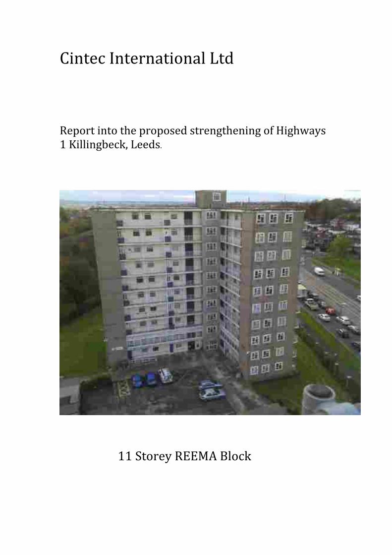
Cintec International Ltd Report into the proposed strengthening of Highways 1 Killingbeck, Leeds.
11 Storey REEMA Block
REEMA The Reema companies’ first housing contracts started in 1948. In 1956 they introduced three-‐storey flats and in 1958 multi-‐storey flats were added to the product range. Large numbers of Reema large panel system dwellings were constructed during the 1960s and early 1970s. In common with other large panel systems, those produced by Reema are based upon large storey height precast reinforced concrete panels. The edge details to the wall and floor units form cavities which are filled with in-‐situ concrete forming a structure where continuity is provided by reinforcement embedded in these joints. Three basic systems were produced by Reema. These were Hollow Panel, Conclad, introduced in response to the improved thermal insulation standards required by the 1965 Building Regulations, and Contrad introduced in 1969. All three of these were developed over a number of years. A range of components were developed from which designers could construct a building. As such variations in construction and joints are widespread and it is probable that no two Reema developments are alike. The design of the Reema developments was to the codes of practice applicable at the time. Therefore they were not designed to withstand the effects of disproportionate collapse as defined by the Part A of the Building Regulations that were introduced in response to the collapse of part of Ronan Point in 1969. Any modification to a large panel system building should only be considered in conjunction with an appraisal of the buildings ability to resist any accidental actions. Highways One Highways One was constructed in 1962, no archive records have been located in relation to structural design of Highways One or Two. We do have a number of drawings for ‘Leeds Multi-‐Storey Flats Contract 679’ undertaken by the engineering practice Felix J Samuely & Partners with the City Architect R.H. Levitt. The drawings are dated 1958 and show the arrangement for a typical ten-‐storey Reema tower block. The drawings are included in Appendix B. The structural arrangements for the superstructure are missing; however some of the architects drawings are available. Both Highways One and Two are similar in general arrangement and may have been constructed in accordance with these proposals. The drawings, with reference to the BRE document ‘Reema Large Panel System Dwellings: Constructional Details’ indicate that the building is constructed from the following key components; Component Product Reference Comment External Wall -‐ load bearing
Conclad panel; 8½ inch thick comprising 3½ inch thick concrete external skin
Alternatively this may be 7 inch Sandwich Panel. This will only be able to be confirmed via an intrusive investigation from within a two bedroom dwelling.
External Wall Celcore panel;
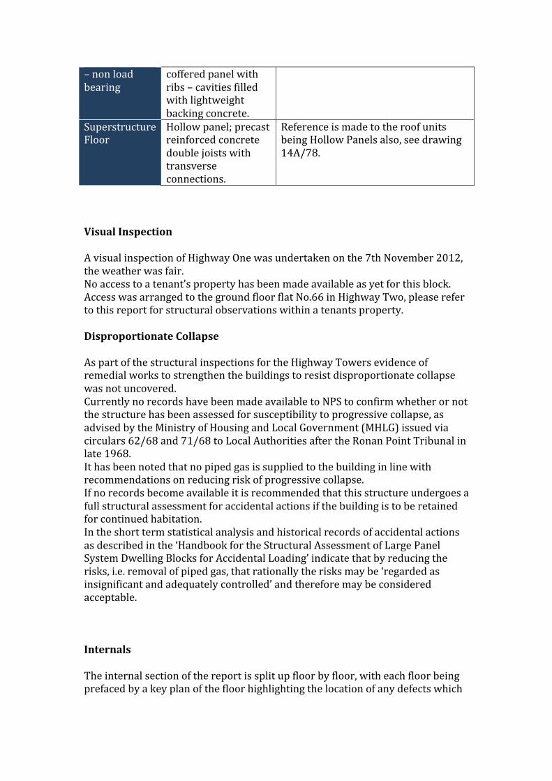
– non load bearing
coffered panel with ribs – cavities filled with lightweight backing concrete.
Superstructure Floor
Hollow panel; precast reinforced concrete double joists with transverse connections.
Reference is made to the roof units being Hollow Panels also, see drawing 14A/78.
Visual Inspection A visual inspection of Highway One was undertaken on the 7th November 2012, the weather was fair. No access to a tenant’s property has been made available as yet for this block. Access was arranged to the ground floor flat No.66 in Highway Two, please refer to this report for structural observations within a tenants property. Disproportionate Collapse As part of the structural inspections for the Highway Towers evidence of remedial works to strengthen the buildings to resist disproportionate collapse was not uncovered. Currently no records have been made available to NPS to confirm whether or not the structure has been assessed for susceptibility to progressive collapse, as advised by the Ministry of Housing and Local Government (MHLG) issued via circulars 62/68 and 71/68 to Local Authorities after the Ronan Point Tribunal in late 1968. It has been noted that no piped gas is supplied to the building in line with recommendations on reducing risk of progressive collapse. If no records become available it is recommended that this structure undergoes a full structural assessment for accidental actions if the building is to be retained for continued habitation. In the short term statistical analysis and historical records of accidental actions as described in the ‘Handbook for the Structural Assessment of Large Panel System Dwelling Blocks for Accidental Loading’ indicate that by reducing the risks, i.e. removal of piped gas, that rationally the risks may be ‘regarded as insignificant and adequately controlled’ and therefore may be considered acceptable. Internals The internal section of the report is split up floor by floor, with each floor being prefaced by a key plan of the floor highlighting the location of any defects which
will then be expended upon in the text and if necessary illustrated with a relevant photograph. On all but one floor the survey was restricted to the communal spaces including the cantilever balcony access walkways, stairs, main circulation space and, where accessible, the drying room. Strengthening Works to Reema Large Panel System Residential Blocks Introduction Housing Leeds, part of Leeds City Council, and NPS Leeds has recently undertaken condition surveys on a number of their high rise residential tower blocks. During these investigations it has been discovered that a number of the prefabricated large panel system tower blocks have not had structural assessments for a number of years. There is limited archive information regarding the structural works undertaken for construction and records of any continued maintenance or remediation works. Presently the high rise towers are subject to annual steeplejack assessments to remove loose cladding and identify any on-‐going issues to the façade. As part of the programme for prolonging asset life and upgrading properties to improve tenants comfort the Highways One has been identified as the first tower to be strengthened to meet the requirements as advised by the Ministry of Housing and Local Government (MHLG) issued via circulars 62/68 and 71/68 to Local Authorities after the Ronan Point Tribunal in late 1968. The Client has decided to adopt the approach of directly undertaking strengthening works to this tower to minimise undertaking significant intrusive sampling required to undertake an analytical structural assessment and reduce the lead in time to enable the works to be undertaken. To undertake this work Housing Leeds and NPS Leeds are seeking to engage a structural engineer with a track record in high rise residential towers to develop the required details to undertake the strengthening works. Alongside the strengthening works the building is to be over clad to improve thermal efficiency. It was then recommended that Cintec International Ltd who had a specialised anchoring and reinforcing range of products that were designed to overcome the many problems encountered with this form of hollow pot concrete construction to provide suitable cost effective measure to structurally strengthen the buildings. Cintec’s Northern Area representative was called in to give advice on the specific problem relating to the external walls and their connection to the floor slabs. After consultation Cintec International Ltd employed the services of Arup Consulting Engineers to provide additional structural advice to particularly investigate the structural condition of the connection of the external walls to the hollow concrete floor slabs. After review the detailed report provided by NPS Consultants it was considered desirable to have a meeting with all the parties concerned with the proposed strengthening to confirm the way ahead. On 22nd October 2014 East/North East Homes, NPS, Arup and Cintec met in Leeds to discuss the various issues. After, much discussion it was agreed that a
more detailed examination should take place to carry out a full intrusive test to determine the structural detail at the wall and floor and the supports at areas critical to a structural assessment for the Post Ronan Point analysis requirement. The initial site investigation and concrete survey would be carried as a matter of urgency on the first week of December 2014. The scope of work was covered in Cintec’s proposals to NPS on the 12th November 2014. The inspection took place on the second week of December 2014 following erection of the working platforms provided by the client. Scaffold access was provided to the eastern end of Highways I and Highways 2 up to the first floor. It was decided that the floor and wall connection on the Highways 1 was the best area to open to view the internal connections. Also, diamond drilled 60 mm core holes were drilled on a return panel to establish the form of construction on that part of the walls. Unfortunately, it was not possible at that time due to the Christmas Holidays to undertake internal destructive testing that would impede on the occupants celebrations. The results of this first investigation were discussed in full at a meeting on 3rd February 2015 with a further recommendation to immediately conduct a second investigation within the next two weeks including installing test anchors in the end of the concrete joist that formed part of the hollow floor beams. A flat was made available and opening up internally took place on 12th February 2015. With the geometry of the construction confirmed a Cintec anchor load test was carried out on site to assist in finalising the design arrangements for the structural strengthening of the refurbishment project. Structural Trial hole November 2014 It can be seen in the annotated photographs that the area selected for trial bore hole I, shown in figure 1 provided good access at a wall to floor joint at a panel junction. The specific investigation trial hole is shown in Photograph 2, illustrating the junction between the precast concrete floor slab and the panel connection from ground to first floor (refer to the Cintec sketches). The panel connections are vertical projecting bolts into receiving steel plate for the panel above to be lowered onto. The floor precast units are positioned on the inside face of the panel below. The very limited investigation available of this detail gave concern because it appears that there is only a proportionally small structural bearing of the floor units on to the wall concrete below is seen in Photograph 3. Furthermore, the hoped for connecting details of reinforcement and hook bars into the floor slabs, was not present, with only three 6mm diameter (approximately) wires bent into the insitu infill concrete cast between the precast floor and wall elements shown in Photograph 4. This was seen to indicate a very poor structural joint and it is not known at this time how the construction of this detail took place. Then: appears to be no records and little information available at present. Therefore, based on this limited opening up, a significant question mark is posed over the structural integrity of this bearing connection.
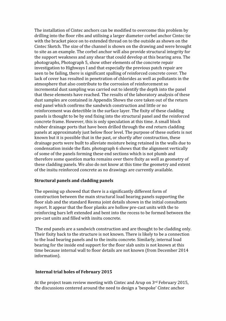
The installation of Cintec anchors can be modified to overcome this problem by drilling into the floor ribs and utilising a larger diameter corbel anchor Cintec tie with the bracket piece on to extended thread on to the outside as shown on the Cintec Sketch. The size of the channel is shown on the drawing and were brought to site as an example. The corbel anchor will also provide structural integrity for the support weakness and any shear that could develop at this bearing area. The photographs, Photograph 5, show other elements of the concrete repair investigation to Highways I and that especially the previous patch repair are seen to be failing, there is significant spalling of reinforced concrete cover. The lack of cover has resulted in penetration of chlorides as well as pollutants in the atmosphere that also contribute to the corrosion of reinforcement so incremental dust sampling was carried out to identify the depth into the panel that these elements have reached. The results of the laboratory analysis of these dust samples are contained in Appendix Shows the core taken out of the return end panel which confirms the sandwich construction and little or no reinforcement was detectible in the surface layer. The fixity of these cladding panels is thought to be by end fixing into the structural panel and the reinforced concrete frame. However, this is only speculation at this time. A small block rubber drainage ports that have been drilled through the end return cladding panels at approximately just below floor level. The purpose of these outlets is not known but it is possible that in the past, or shortly after construction, these drainage ports were built to alleviate moisture being retained in the walls due to condensation inside the flats. photograph 6 shows that the alignment vertically of some of the panels forming these end sections which is not plumb and therefore some question marks remains over there fixity as well as geometry of these cladding panels. We also do not know at this time the geometry and extent of the insitu reinforced concrete as no drawings are currently available. Structural panels and cladding panels The opening up showed that there is a significantly different form of construction between the main structural load bearing panels supporting the floor slab and the standard Reema joint details shown in the initial consultants report. It appear that the floor planks are hollow pre-‐cast units with the to reinforcing bars left extended and bent into the recess to be formed between the pre-‐cast units and filled with insitu concrete. The end panels are a sandwich construction and are thought to be cladding only. Their fixity back to the structure is not known. There is likely to be a connection to the load bearing panels and to the insitu concrete. Similarly, internal load bearing for the inside end support for the floor slab units is not known at this time because internal wall to floor details are not known (from December 2014 information). Internal trial holes of February 2015 At the project team review meeting with Cintec and Arup on 3rd February 2015, the discussions centered around the need to design a 'bespoke' Cintec anchor
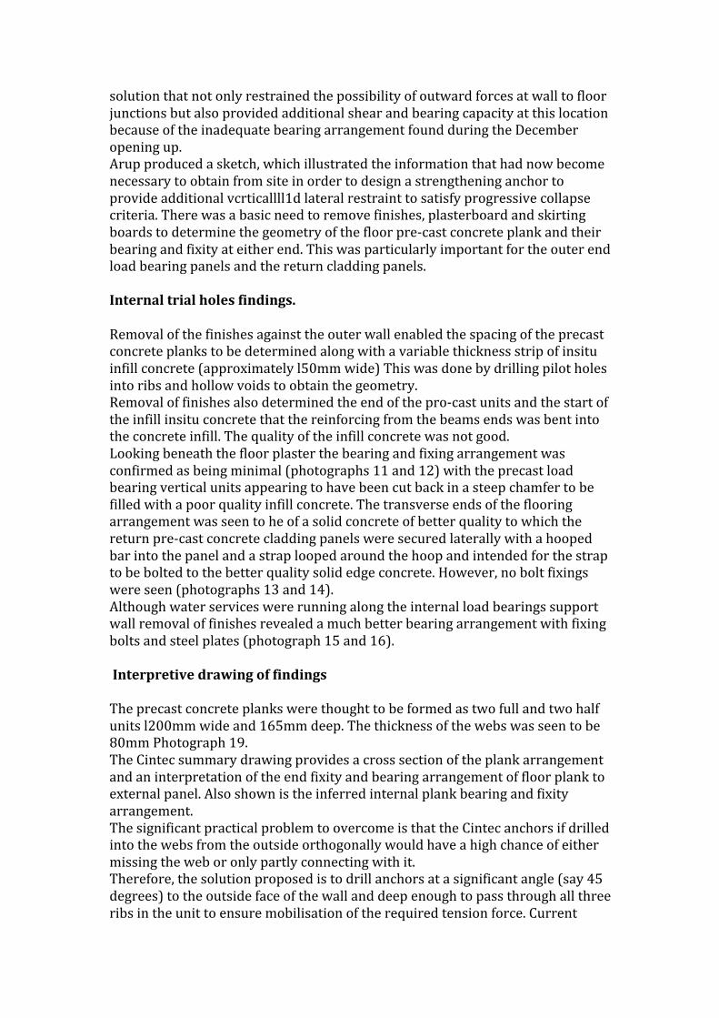
solution that not only restrained the possibility of outward forces at wall to floor junctions but also provided additional shear and bearing capacity at this location because of the inadequate bearing arrangement found during the December opening up. Arup produced a sketch, which illustrated the information that had now become necessary to obtain from site in order to design a strengthening anchor to provide additional vcrticallll1d lateral restraint to satisfy progressive collapse criteria. There was a basic need to remove finishes, plasterboard and skirting boards to determine the geometry of the floor pre-‐cast concrete plank and their bearing and fixity at either end. This was particularly important for the outer end load bearing panels and the return cladding panels. Internal trial holes findings. Removal of the finishes against the outer wall enabled the spacing of the precast concrete planks to be determined along with a variable thickness strip of insitu infill concrete (approximately l50mm wide) This was done by drilling pilot holes into ribs and hollow voids to obtain the geometry. Removal of finishes also determined the end of the pro-‐cast units and the start of the infill insitu concrete that the reinforcing from the beams ends was bent into the concrete infill. The quality of the infill concrete was not good. Looking beneath the floor plaster the bearing and fixing arrangement was confirmed as being minimal (photographs 11 and 12) with the precast load bearing vertical units appearing to have been cut back in a steep chamfer to be filled with a poor quality infill concrete. The transverse ends of the flooring arrangement was seen to he of a solid concrete of better quality to which the return pre-‐cast concrete cladding panels were secured laterally with a hooped bar into the panel and a strap looped around the hoop and intended for the strap to be bolted to the better quality solid edge concrete. However, no bolt fixings were seen (photographs 13 and 14). Although water services were running along the internal load bearings support wall removal of finishes revealed a much better bearing arrangement with fixing bolts and steel plates (photograph 15 and 16). Interpretive drawing of findings The precast concrete planks were thought to be formed as two full and two half units l200mm wide and 165mm deep. The thickness of the webs was seen to be 80mm Photograph 19. The Cintec summary drawing provides a cross section of the plank arrangement and an interpretation of the end fixity and bearing arrangement of floor plank to external panel. Also shown is the inferred internal plank bearing and fixity arrangement. The significant practical problem to overcome is that the Cintec anchors if drilled into the webs from the outside orthogonally would have a high chance of either missing the web or only partly connecting with it. Therefore, the solution proposed is to drill anchors at a significant angle (say 45 degrees) to the outside face of the wall and deep enough to pass through all three ribs in the unit to ensure mobilisation of the required tension force. Current
estimate is four anchors through the larger panel and three in the two smaller panels. In this way, the anchor will provide ensured lateral restraint and 10 number 16mm high strength stainless steel threaded reinforcing bars will provide both adequate shear and additional bearing fixity to safeguard against progressive collapse. Anchor load test. The photograph 17 in shows the load test rig and the results of two tests are shown on the test certificate. It is clear from the test anchor (which was based upon fixity in to one rib only) that the pull-‐out capacity is in excess of 20 kn per anchor Photograph 18. It is necessary in view of the lack of drawing record and design information to produce a new Cintec anchor strengthening design following the structural data gathering. In view of the obvious difficulties involve with gaining access to units then structurally it is only possible to design a 'bespoke' Cintec anchor solution that will ensure against progressive collapse of the outside end panels and secondary return cladding panels. There is no information about how the insitu reinforced concrete is connected to the Reema panels and limited information found from the February 2015 work how connection and load paths have been designed and constructed. However, the part of the arrangement opened up revealed a much better bearing and fixity than the outside panel. Recommended Anchor Layouts-‐ single flat.
Floor plan, Anchor Layout
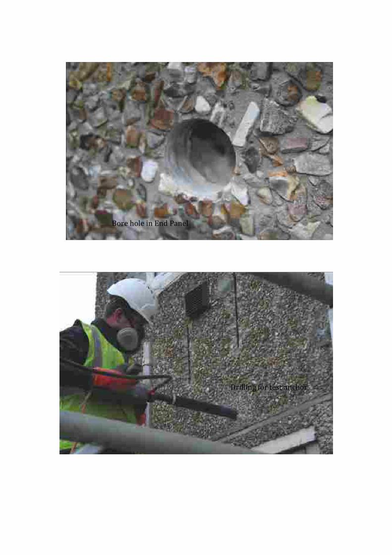
Bore hole in End Panel
Drilling for test anchor
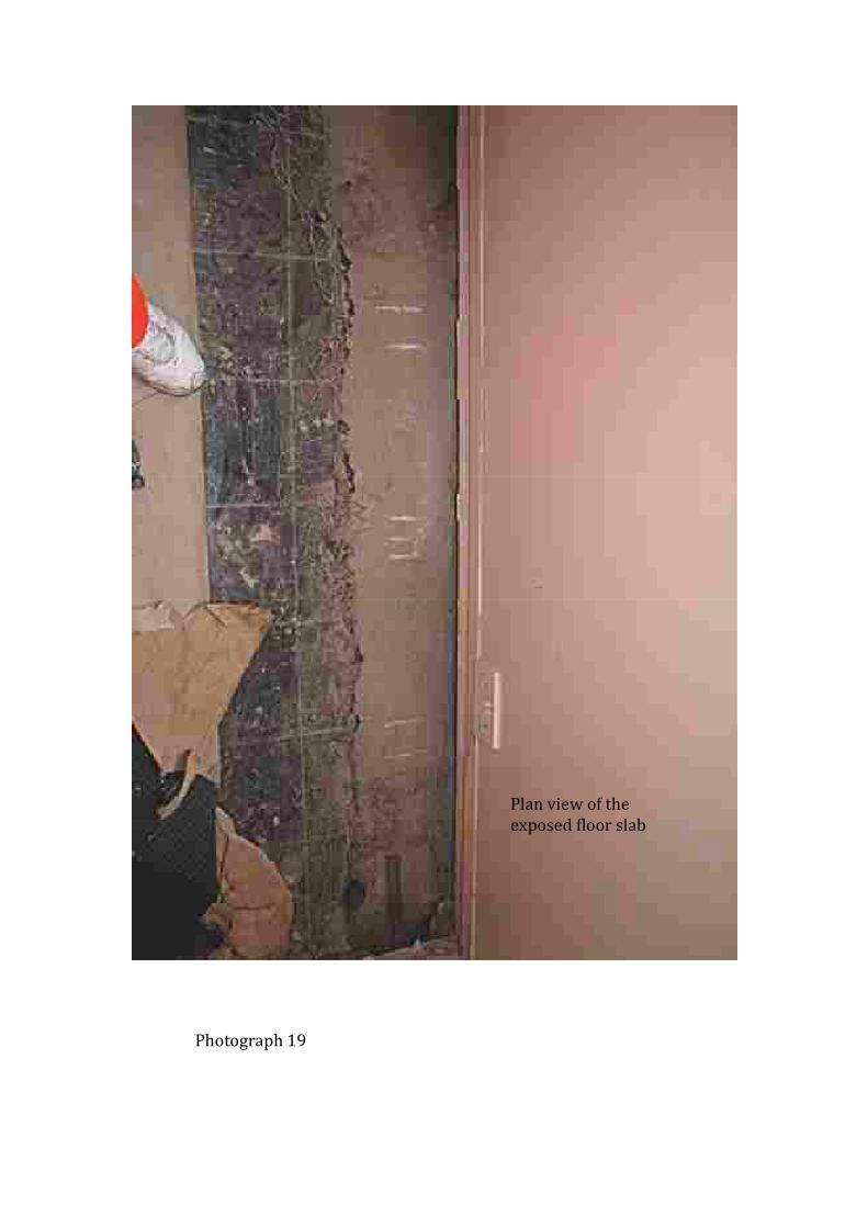
Plan view of the exposed floor slab
Photograph 19
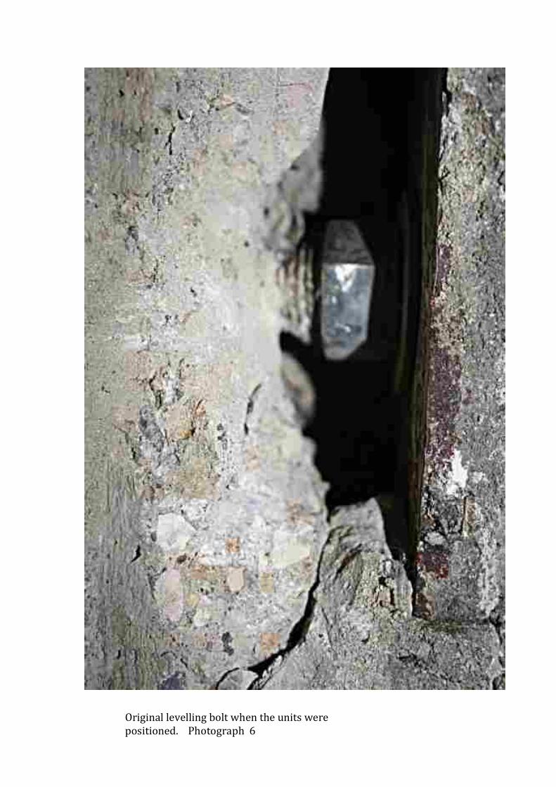
Original levelling bolt when the units were positioned. Photograph 6
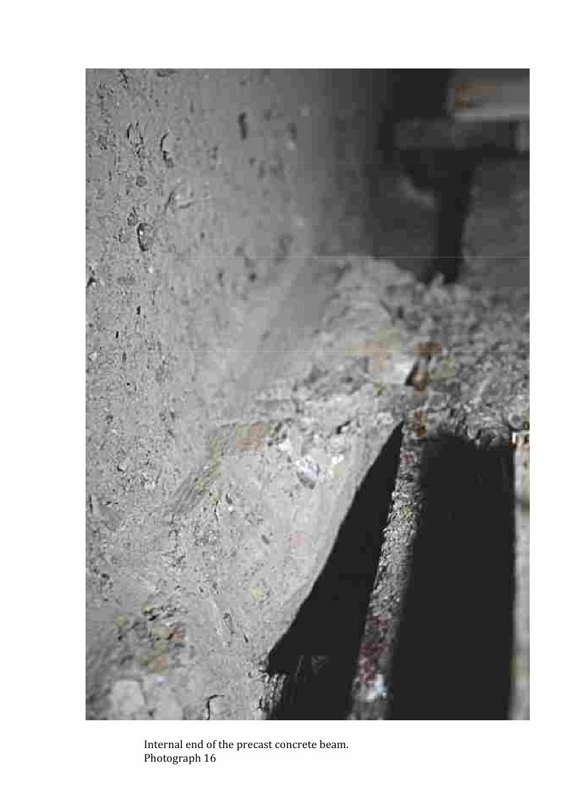
Internal end of the precast concrete beam. Photograph 16
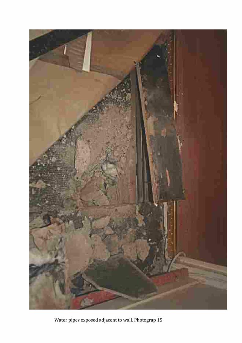
Water pipes exposed adjacent to wall. Photograp 15
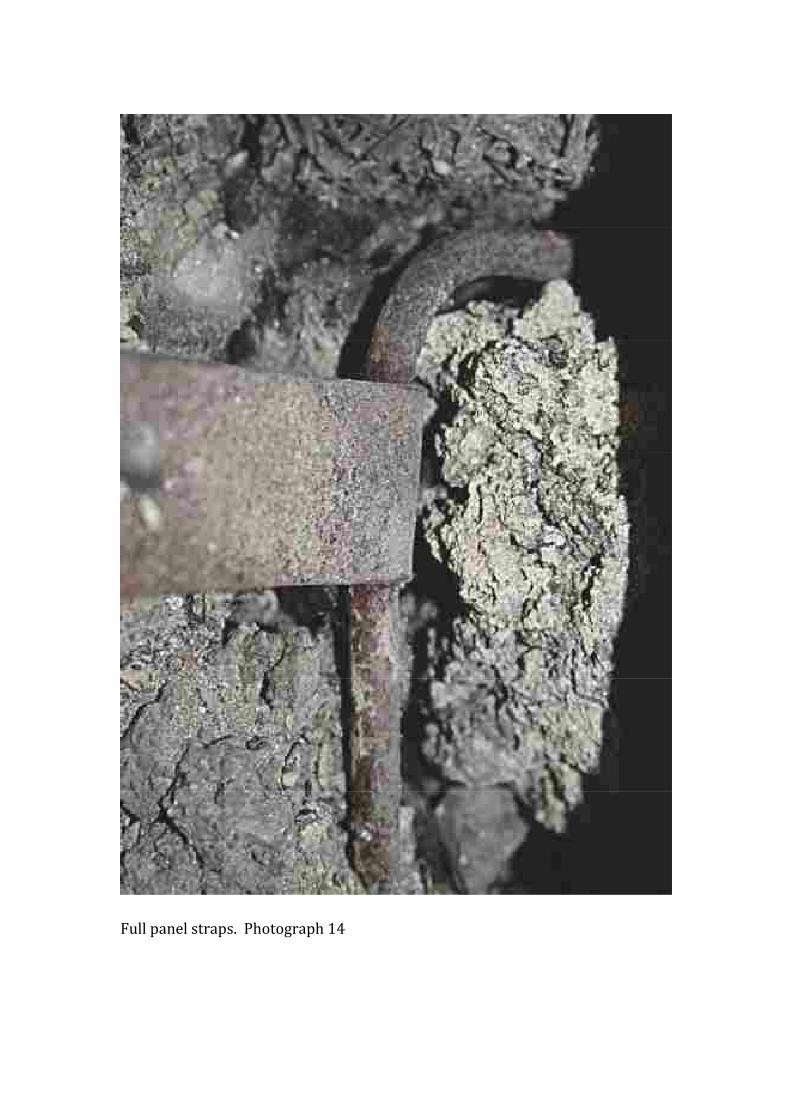
Full panel straps. Photograph 14
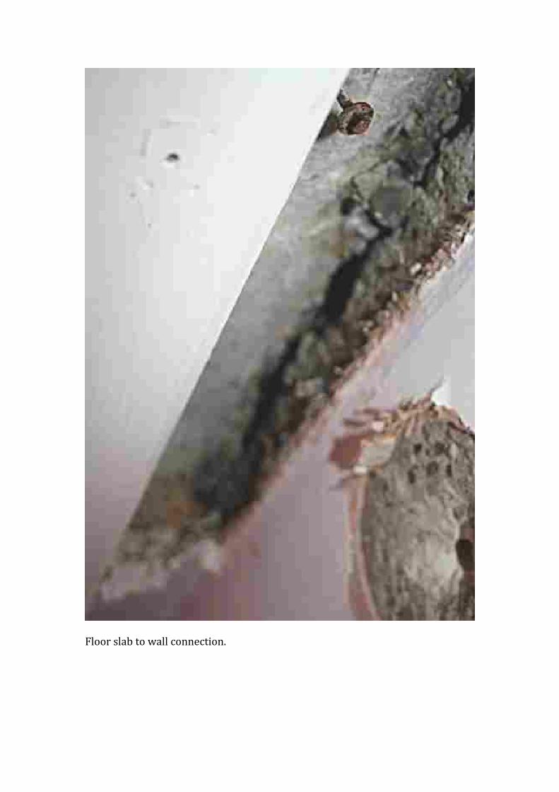
Floor slab to wall connection.
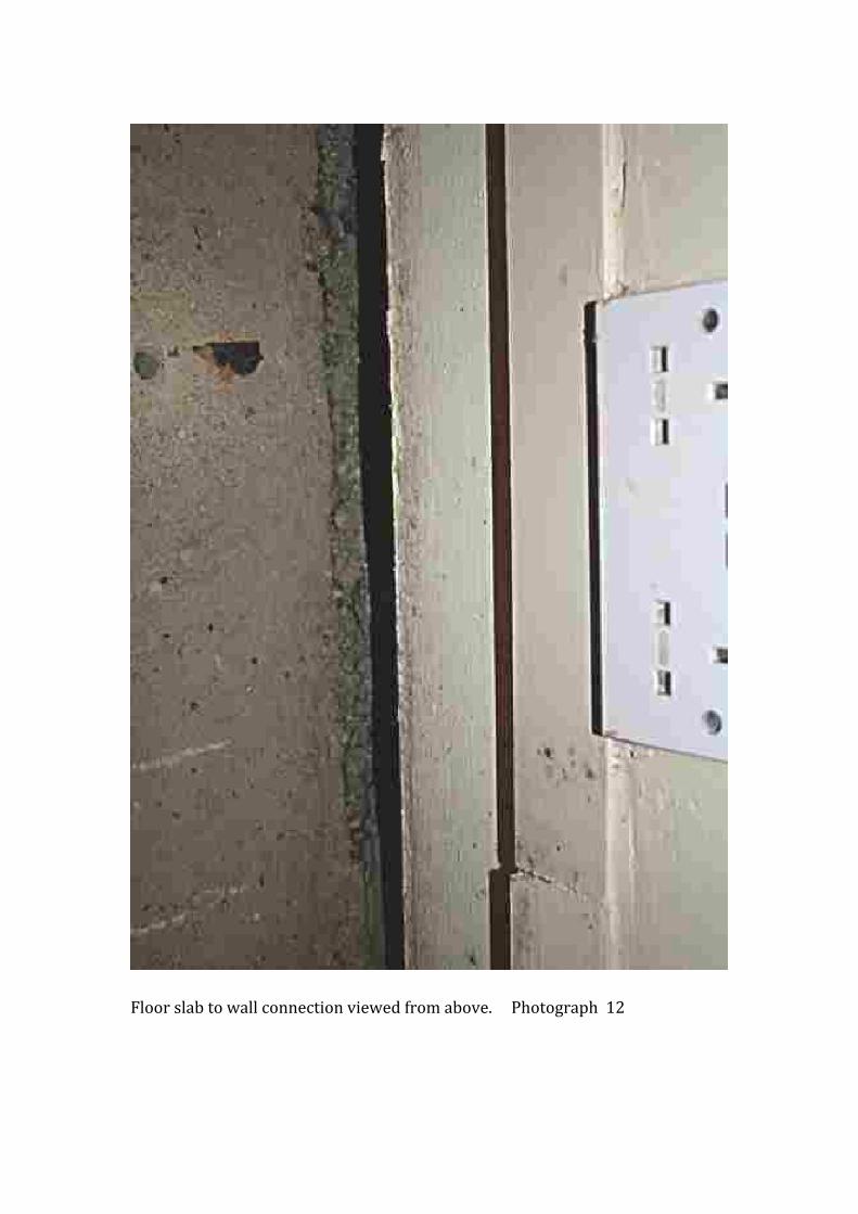
Floor slab to wall connection viewed from above. Photograph 12
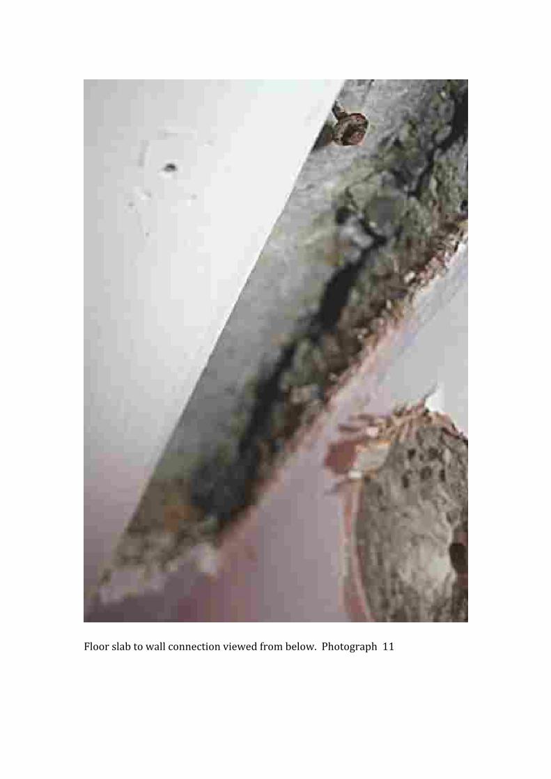
Floor slab to wall connection viewed from below. Photograph 11

Photograph 4
Hollow pot detail.
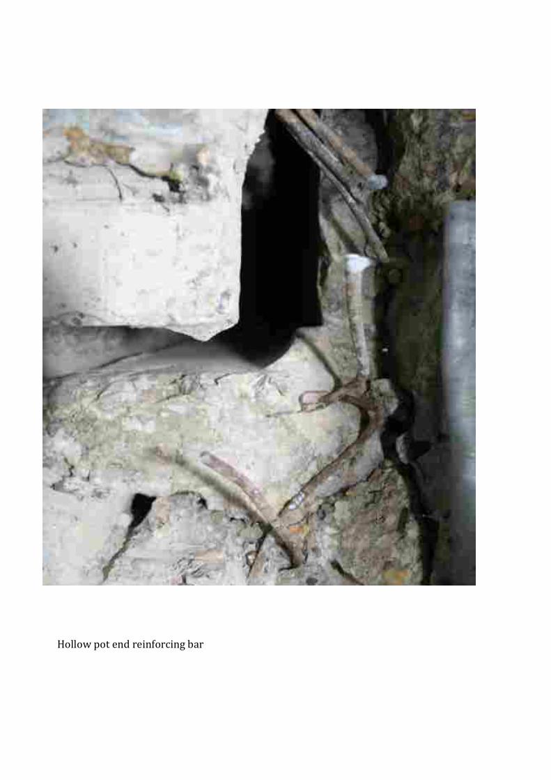
Hollow pot end reinforcing bar
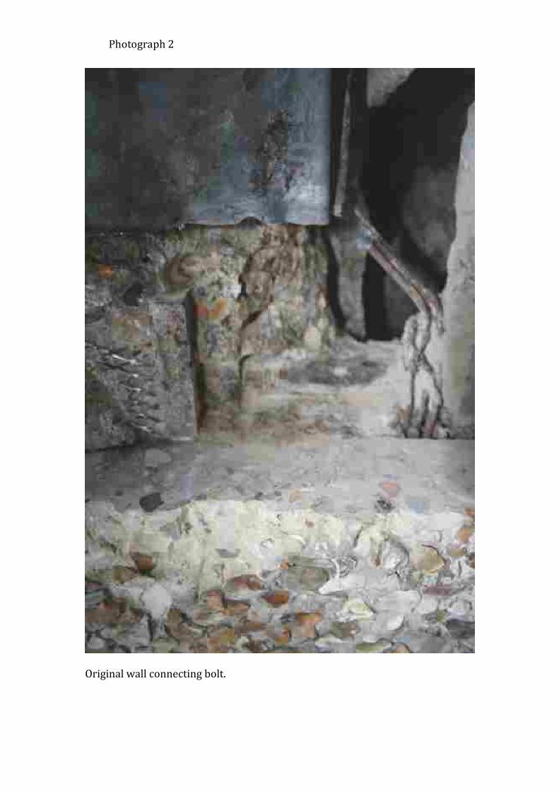
Original wall connecting bolt.
Photograph 2

Original strap. Photograph 13
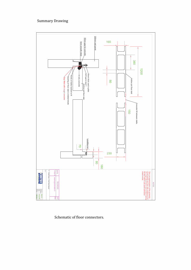
Schematic of floor connectors.
Summary Drawing
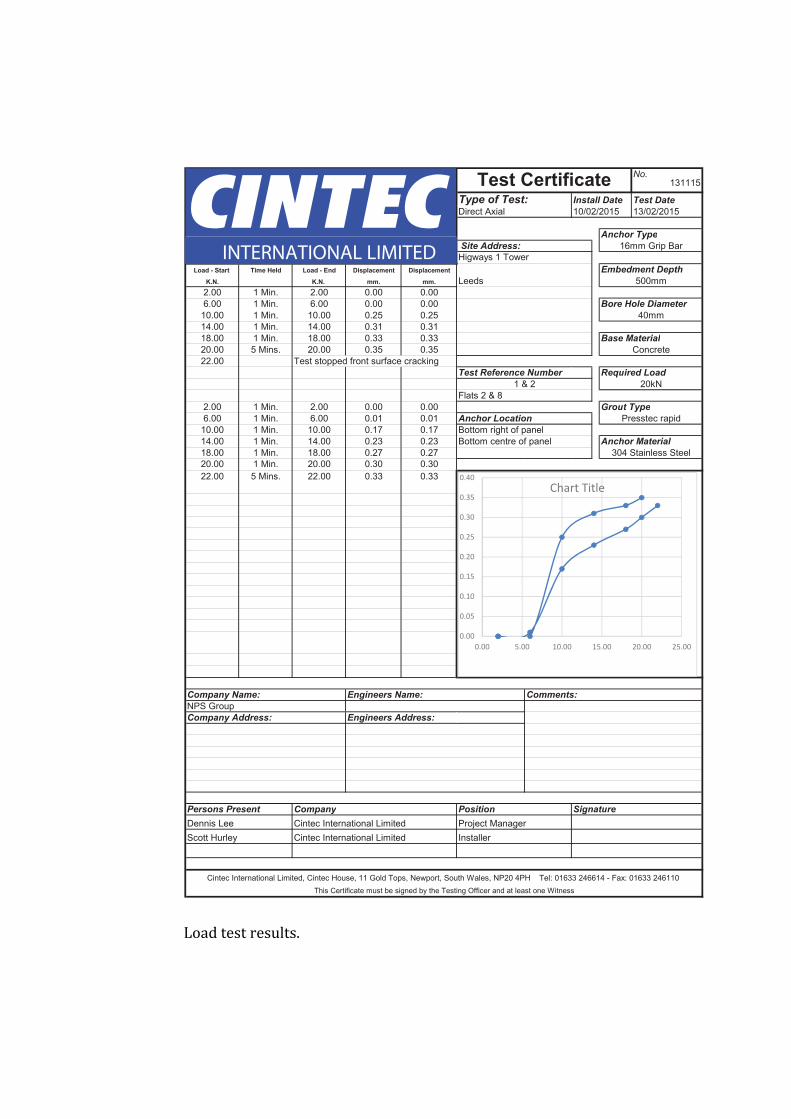
Load test results.
No.131115
Type of Test: Install Date Test Date
Anchor Type
Site Address:
Higways 1 TowerLoad - Start Time Held Load - End Displacement Displacement Embedment Depth
.mm.mm .N.K.N.K Leeds2.00 1 Min. 2.00 0.00 0.006.00 1 Min. 6.00 0.00 0.00 Bore Hole Diameter
10.00 1 Min. 10.00 0.25 0.2514.00 1 Min. 14.00 0.31 0.3118.00 1 Min. 18.00 0.33 0.33 Base Material
20.00 5 Mins. 20.00 0.35 0.3522.00 Test stopped front surface cracking
Test Reference Number Required Load
2.00 1 Min. 2.00 0.00 0.00 Grout Type
6.00 1 Min. 6.00 0.01 0.01 Anchor Location
10.00 1 Min. 10.00 0.17 0.1714.00 1 Min. 14.00 0.23 0.23 Anchor Material
18.00 1 Min. 18.00 0.27 0.2720.00 1 Min. 20.00 0.30 0.3022.00 5 Mins. 22.00 0.33 0.33
Company Name: Engineers Name:
Company Address: Engineers Address:
Persons Present Company Position Signature
NPS Group
Cintec International Limited, Cintec House, 11 Gold Tops, Newport, South Wales, NP20 4PH Tel: 01633 246614 - Fax: 01633 246110This Certificate must be signed by the Testing Officer and at least one Witness
Cintec International LimitedCintec International Limited
Dennis LeeScott Hurley
Project ManagerInstaller
304 Stainless Steel
Comments:
1 & 2Flats 2 & 8
Bottom right of panelBottom centre of panel
10/02/2015 13/02/2015
16mm Grip Bar
Direct Axial
Test Certificate
Presstec rapid
500mm
40mm
Concrete
20kN
INTERNATIONAL LIMITED
DISPLACEMENT
GRAPH
0.00
0.05
0.10
0.15
0.20
0.25
0.30
0.35
0.40
0.00 5.00 10.00 15.00 20.00 25.00
Chart Title
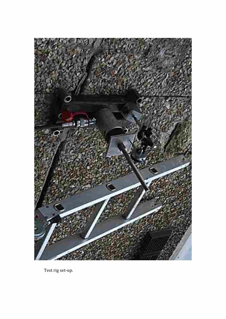
Test rig set-‐up.

20 KN test load shown on gauge
Pho