Embed Size (px)
DESCRIPTION
Investigating the potential of high rise buildings.
Citation preview
NORTHEASTERN UNIVERSITYARCH 7130 / FALL 2014
HIGHRISEDYNAMIC
ASYMMETRIC
TWISTINGSUBMERGED
SLANTING
OVERHANGING
SUBTERRANIAN
THEUNVEILING THE POTENTIALS
OF TALL BUILDINGS

02
This publication has been prepared as a part of the 2014 Master’s Research Studio in the Northeastern University School of Architecture. All research and content in this publication was produced by tvhe “How Tall Buildings Meet the Ground” studio research team.
Published byNortheastern University School of Architecture360 Huntington AvenueBoston, Massachusetts 02215
Copyright 2014 byNortheastern University School of Architecture
All rights reserved
03RESEARCH TEAMPREFACE
This book was created by the 2014-2015 studio“How Tall Buildings Meet The Ground”
FACULTY:
Carlos Zapata Daniel Belknap
RESEARCH TEAM:
Amani AlmuwallidAreta BrucicCarolina ClementeChristine Cutry Huda ArshadlamphonKevin ChungMiguel EspinoNathan EllenbergerRoaa Badwood
04
05
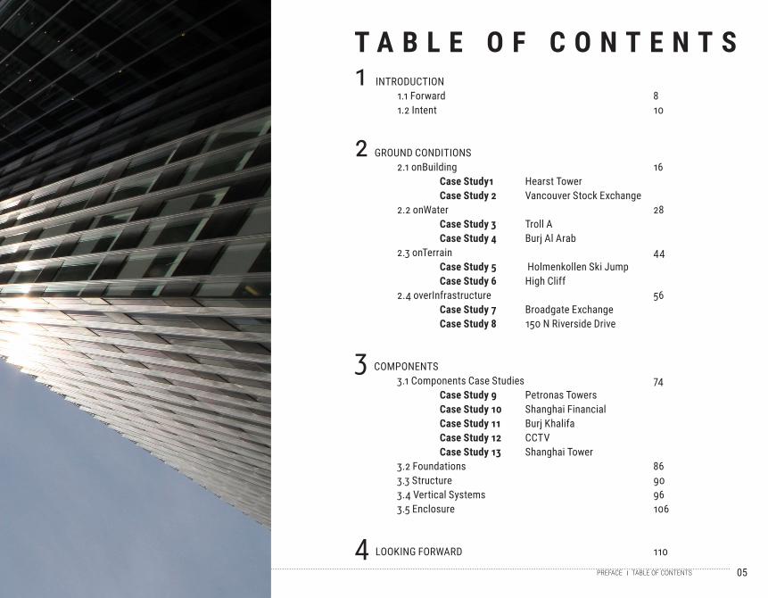
1 INTRODUCTION 1.1 Forward 8 1.2 Intent 10
2 GROUND CONDITIONS 2.1 onBuilding 16 Case Study1 Hearst Tower Case Study 2 Vancouver Stock Exchange 2.2 onWater 28 Case Study 3 Troll A Case Study 4 Burj Al Arab 2.3 onTerrain 44 Case Study 5 Holmenkollen Ski Jump Case Study 6 High Cliff 2.4 overInfrastructure 56 Case Study 7 Broadgate Exchange Case Study 8 150 N Riverside Drive
3 COMPONENTS 3.1 Components Case Studies 74 Case Study 9 Petronas Towers Case Study 10 Shanghai Financial Case Study 11 Burj Khalifa Case Study 12 CCTV Case Study 13 Shanghai Tower 3.2 Foundations 86 3.3 Structure 90 3.4 Vertical Systems 96 3.5 Enclosure 106
4 LOOKING FORWARD 110
T A B L E O F C O N T E N T S
PREFACE TABLE OF CONTENTS

06
07
I N T R O D U C T I O N1
The thesis of this class is “How Tall Buildings Meet the Ground.” An extensive research of tall buildings has
been performed, and many discoveries about tall buildings have been made. Here we wish to introduce the
research that is presented within this book, and give a clear insight into what is being studied and why it is
being studied.
08 FOREWORDINTRODUCTION
This book summarizes the research semester of a two semester course on High Rise design at the Graduate School of Architecture at Northeastern University. This is the third consecutive year of high-rise research that has been explored under the direction of different faculty. The first year, led by Blake Middleton of Handel Architects and David Turturo of Bruner/Cott & Associates, focused on tall buildings in historic centers. The second year of the series, taught by Gary Haney, Aybars Asci, and Marta Nowak of Skidmore, Owings, and Merrill, explored efficiency in tall buildings by developing a system of parametric formulas.
The research of these two studios has been available to our students as reference material.
This course, the third round of the high-rise series, is a two-semester research and design course focused on the way tall structures meet the ground. Given how many of these structures are in the planning, design, and construction stages around the world and how much of an impact these large structures can have on the urban experience, this is an indispensable body of research.
There are many definitions of ground. It could be considered the plane at which the building is entered by the users, but it also may be an elevated plane, the top of a building, an underground point of access, or the surface of a body of water. In order to develop a more strategic understanding of how to deal with the ground before starting the design of their own projects, students have analyzed a group of tall structures that meet the ground in a range of challenging conditions, dealing with geographical restrictions, large scale transportation infrastructure, under water conditions, and sites occupied by existing landmark structures. They have con-ducted a focused analysis on what it takes to build tall structures in these uncon-ventional conditions and have catalogued their findings.
In addition to studying unconventional sites, it was necessary to analyze the more universal principles and systems necessary in high-rise design and construction. The primary tactic for understanding how the necessary systems in tall buildings affect street level architecture is an extensive range of case studies, only a fraction of which were ultimately formatted and included in the final publication. This included understanding the structural characteristics that differentiate tall vertical structures from horizontal structures, as well as the inherent structural differences between low-rise and mid-rise structures. Another key aspect of our research is the
intimate relationship between structure and MEP systems, vertical transportation systems, and enclosure systems. Zoning ordinances, building codes, and other lim-iting factors that tend to shape the form and restrict the expressive qualities of tall structures were also discussed at length.One key finding relates to the identification of the basic modules that make a tall structure, punctuated by structural bracing, or sequential connections between core and external columns in the form of outriggers and belt trusses, and their con-venient relationship to MEP and vertical circulation systems; but also the flexibility with which these devices (systems) can be arranged. In other words, the finding that nothing is absolute and that by taking advantage of this inherent flexibility, we can achieve unlimited means of expression in tall structures.
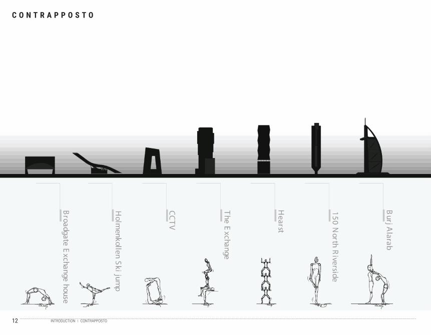
Another ongoing theme of this research semester is that not all tall structures need to be designed in a “soldier” like posture. The realization that advances in technol-ogy allow for increased flexibility in the way the components of tall structures are shaped, stacked, organized, and supported, means that we need to further advance the way tall buildings are imagined. This class has chosen to explain this increase in flexibility and its potential expressive qualities as the “relaxation” of the structure, which is essential in the way this class intends to deal with the way tall structures meet the ground. This class has chosen to study tall structures the imply a sense of “contrapposto”, making an analogy to the way in which the distribution of weight in figurative Greek and Roman sculpture recognizes the way in which the human body changes (adapts) its posture to achieve a balanced weight distribution as the body rests on a surface or ground.
The final phase of this semester requires each student to identify a particular ground condition and strategy, select a site and propose a program that will guide them to explore potential ways of grounding a tall structure. These proposals are included at the end of this research book. It will be interesting to follow how these initial ideas take shape during the Spring semester.
Carlos ZapataDan Belknap

09FOREWORDINTRODUCTION
1.1 F O R E W O R D
10 INTENTINTRODUCTION
11INTENTINTRODUCTION
1.2 I N T E N T
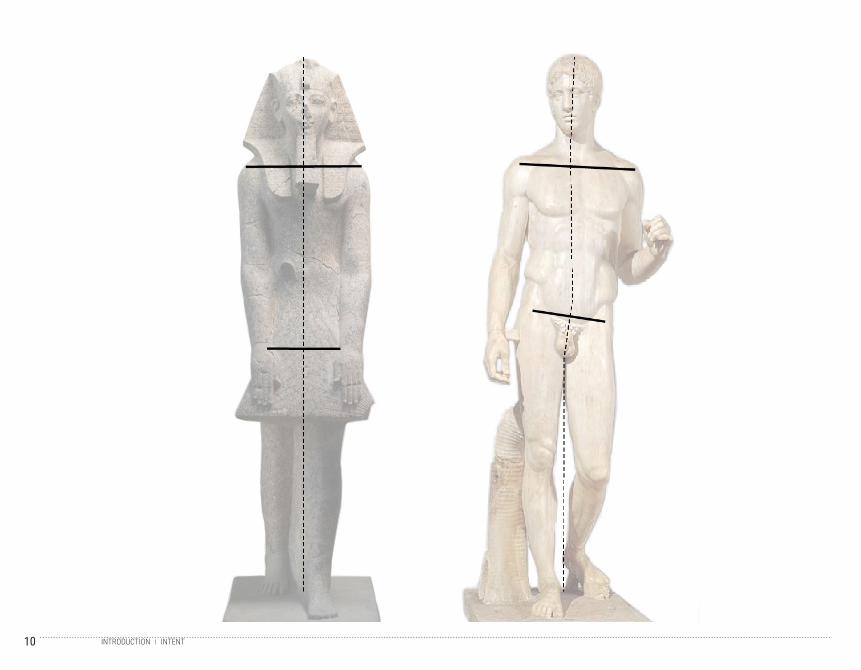
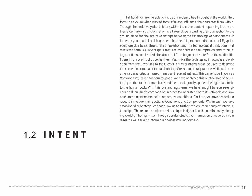
Tall buildings are the eidetic image of modern cities throughout the world. They form the skyline when viewed from afar and influence the character from within. Through their relatively short history within the urban context - spanning little more than a century - a transformation has taken place regarding their connection to the ground plane and the interrelationships between the assemblage of components. In the early years, a tall building resembled the stiff, monumental nature of Egyptian sculpture due to its structural composition and the technological limitations that restricted form. As skyscrapers matured even further and improvements to build-ing practices accelerated, the structural form began to deviate from the soldier-like figure into more fluid opportunities. Much like the techniques in sculpture devel-oped from the Egyptians to the Greeks, a similar analysis can be used to describe the same phenomena in the tall-building. Greek sculptural practice, while still mon-umental, emanated a more dynamic and relaxed subject. This came to be known as Contrapposto; Italian for counter-pose. We have analyzed this relationship of sculp-tural practice to the human body and have analogously applied the high-rise studio to the human body. With this overarching theme, we have sought to reverse-engi-neer a tall building’s composition in order to understand both its rationale and how each component relates to its respective conditions. For here, we have divided our research into two main sections: Conditions and Components. Within each we have established subcategories that allow us to further explore their complex interrela-tionships. These case studies provide unique insights into the continuously chang-ing world of the high-rise. Through careful study, the information uncovered in our research will serve to inform our choices moving forward.
12 CONTRAPPOSTOINTRODUCTION
C O N T R A P P O S T O
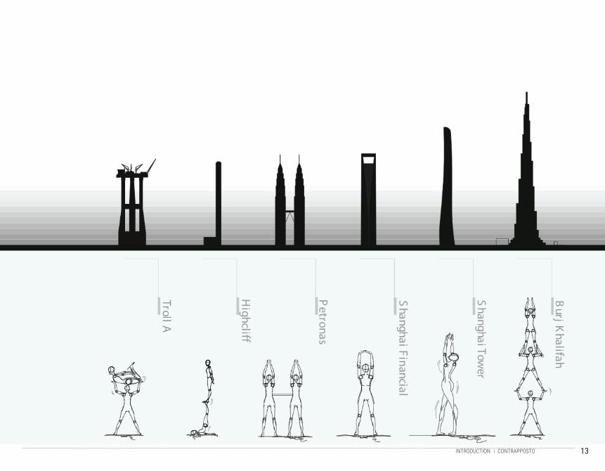
13CONTRAPPOSTOINTRODUCTION

14
15
G R O U N D C O N D I T I O N S2
Ground conditions primarily studies how the tall building meets the ground and establishes its relationship
to the respective context. Within conditions there are four subdivisions: onBuilding, onWater, onTerrain
and overInfrastructure. These are just a handful of broad characterizations for the ground plane that are
dealt within the construction of a high rise building. Each case study does not necessarily reflect one con-
dition completely and several themes have been seen to overlap.
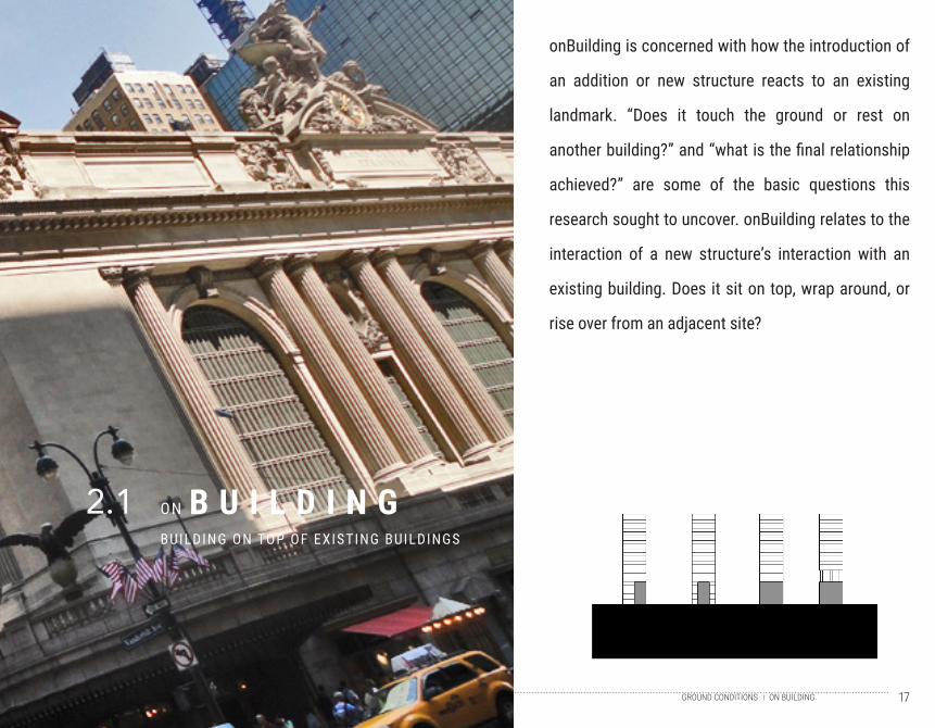
17ON BUILDINGGROUND CONDITIONS
B U I L D I N GBUILDING ON TOP OF EXISTING BUILDINGS
ON2.1
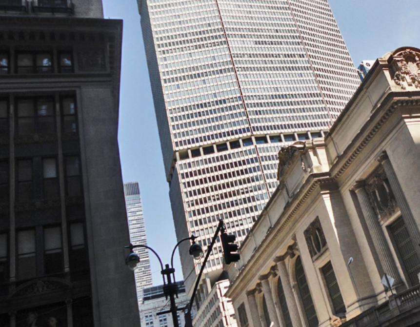
onBuilding is concerned with how the introduction of
an addition or new structure reacts to an existing
landmark. “Does it touch the ground or rest on
another building?” and “what is the final relationship
achieved?” are some of the basic questions this
research sought to uncover. onBuilding relates to the
interaction of a new structure’s interaction with an
existing building. Does it sit on top, wrap around, or
rise over from an adjacent site?
18 TIMELINEON BUILDING
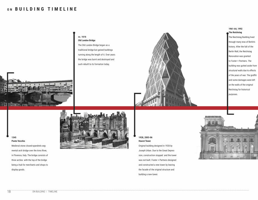
O N B U I L D I N G T I M E L I N E
1345Ponte Vecchio
Medieval stone closed-spandrels seg-
mental arch bridge over the Arno River,
in Florence, Italy. The bridge consists of
three arches with the top of the bridge
being a hub for merchants and shops to
display goods.
cc. 1616Old London Bridge
The Old London Bridge began as a
traditional bridge but gained buildings
running along the length of it. Over years
the bridge was burnt and destroyed and
such rebuilt to its formation today.
1928, 2003-06Hearst Tower
Original building designed in 1928 by
Joseph Urban. Due to the Great Depres-
sion, construction stopped and the tower
was not built. Foster + Partners designed
and constructed a new tower by leaving
the facade of the original structure and
building a new tower.
1961-64, 1992The Reichstag
The Reichstag Building lived
through many eras of Berlin’s
history. After the fall of the
Berlin Wall, the Reichstag
Renovation was granted
to Foster + Partners. The
building was gutted aside from
structural walls due to effects
of the years of war. The graffiti
and some damages were left
on the walls of the original
Reichstag for historical
purposes.
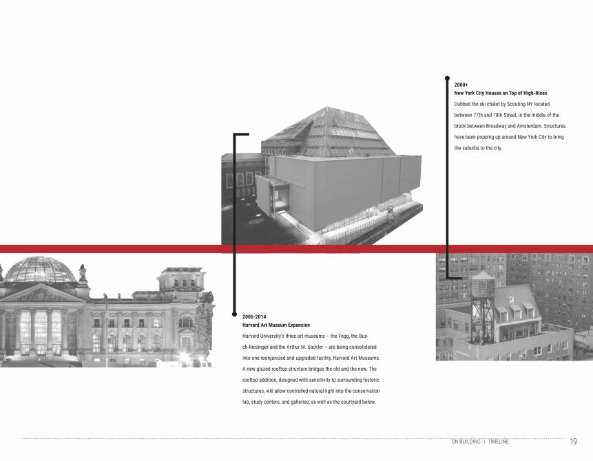
19TIMELINEON BUILDING
2000+New York City Houses on Top of High-Rises
Dubbed the ski chalet by Scouting NY located
between 77th and 78th Street, in the middle of the
block between Broadway and Amsterdam. Structures
have been popping up around New York City to bring
the suburbs to the city.
2006-2014Harvard Art Museum Expansion
Harvard University’s three art museums – the Fogg, the Bus-
ch-Reisinger and the Arthur M. Sackler – are being consolidated
into one reorganized and upgraded facility, Harvard Art Museums.
A new glazed rooftop structure bridges the old and the new. The
rooftop addition, designed with sensitivity to surrounding historic
structures, will allow controlled natural light into the conservation
lab, study centers, and galleries, as well as the courtyard below.
20 HEARST TOWERON BUILDING
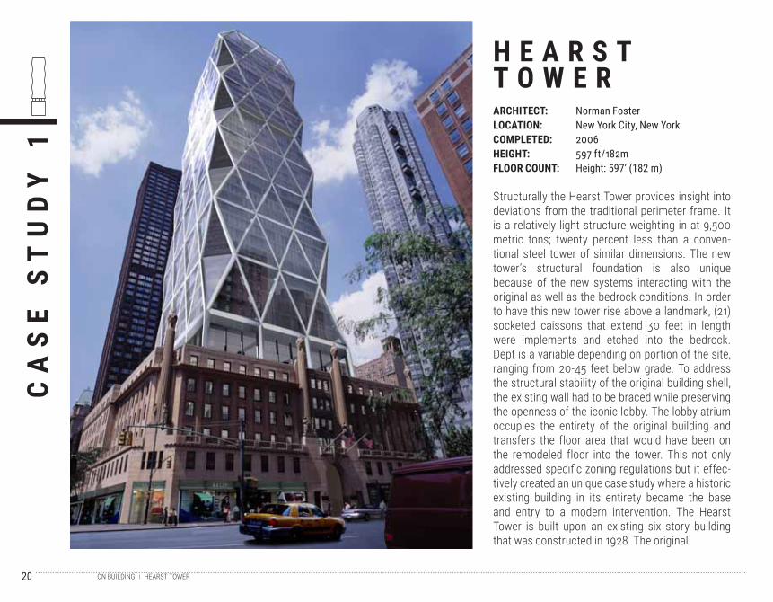
Structurally the Hearst Tower provides insight into deviations from the traditional perimeter frame. It is a relatively light structure weighting in at 9,500 metric tons; twenty percent less than a conven-tional steel tower of similar dimensions. The new tower’s structural foundation is also unique because of the new systems interacting with the original as well as the bedrock conditions. In order to have this new tower rise above a landmark, (21) socketed caissons that extend 30 feet in length were implements and etched into the bedrock. Dept is a variable depending on portion of the site, ranging from 20-45 feet below grade. To address the structural stability of the original building shell, the existing wall had to be braced while preserving the openness of the iconic lobby. The lobby atrium occupies the entirety of the original building and transfers the floor area that would have been on the remodeled floor into the tower. This not only addressed specific zoning regulations but it effec-tively created an unique case study where a historic existing building in its entirety became the base and entry to a modern intervention. The Hearst Tower is built upon an existing six story building that was constructed in 1928. The original
CA
SE
ST
UD
Y 1
H E A R S TT O W E RARCHITECT:LOCATION:COMPLETED:HEIGHT:FLOOR COUNT:
Norman FosterNew York City, New York2006597 ft/182mHeight: 597’ (182 m)
21HEARST TOWERON BUILDING
intention was to construct a high rise that would extend above the art-deco, cast stone facade structure, but was initially put on hold because of the Great Depression. However, the groundwork for the idea of a skyscraper was laid long before Norman Foster designed the structure seen today. Around 80 years alter, the interior of the historic building was gutted and a new 44 story high rise took place in the Manhattan skyline. This cause study showcases the concept of a modern inven-tion in a historic context and is also notable for its sustainable features being the first “green” office tower in New York City.
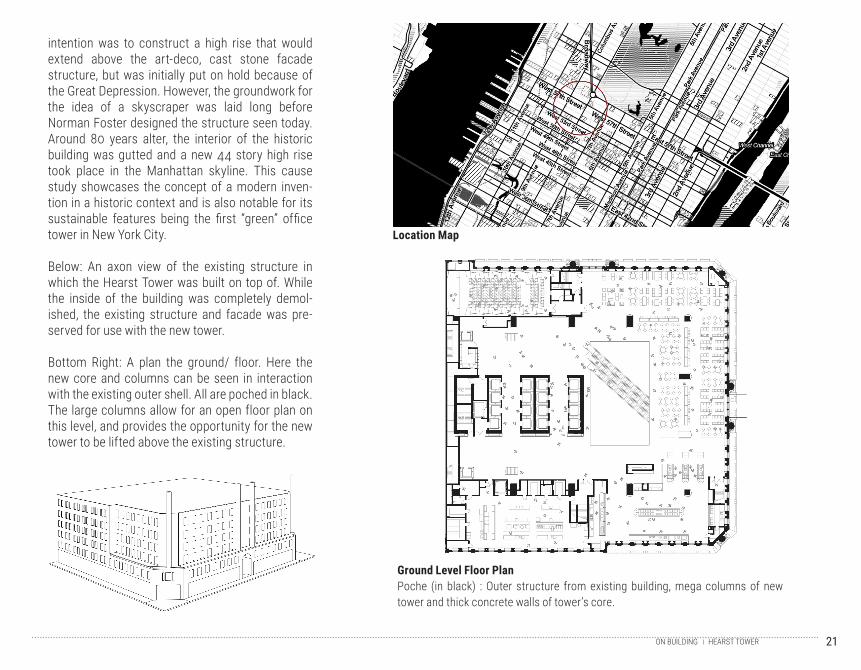
Below: An axon view of the existing structure in which the Hearst Tower was built on top of. While the inside of the building was completely demol-ished, the existing structure and facade was pre-served for use with the new tower.
Bottom Right: A plan the ground/ floor. Here the new core and columns can be seen in interaction with the existing outer shell. All are poched in black. The large columns allow for an open floor plan on this level, and provides the opportunity for the new tower to be lifted above the existing structure.
Location Map
Ground Level Floor Plan Poche (in black) : Outer structure from existing building, mega columns of new tower and thick concrete walls of tower’s core.
22 HEARST TOWERON BUILDING
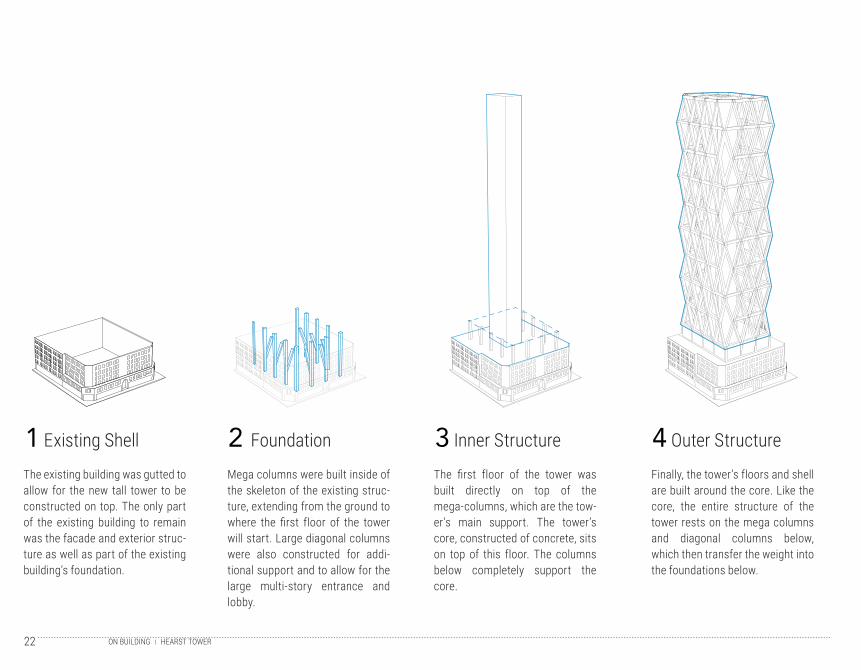
The existing building was gutted to allow for the new tall tower to be constructed on top. The only part of the existing building to remain was the facade and exterior struc-ture as well as part of the existing building’s foundation.
Mega columns were built inside of the skeleton of the existing struc-ture, extending from the ground to where the first floor of the tower will start. Large diagonal columns were also constructed for addi-tional support and to allow for the large multi-story entrance and lobby.
The first floor of the tower was built directly on top of the mega-columns, which are the tow-er’s main support. The tower’s core, constructed of concrete, sits on top of this floor. The columns below completely support the core.
Finally, the tower’s floors and shell are built around the core. Like the core, the entire structure of the tower rests on the mega columns and diagonal columns below, which then transfer the weight into the foundations below.
1 2 3 4Existing Shell Foundation Inner Structure Outer Structure
23HEARST TOWERON BUILDING
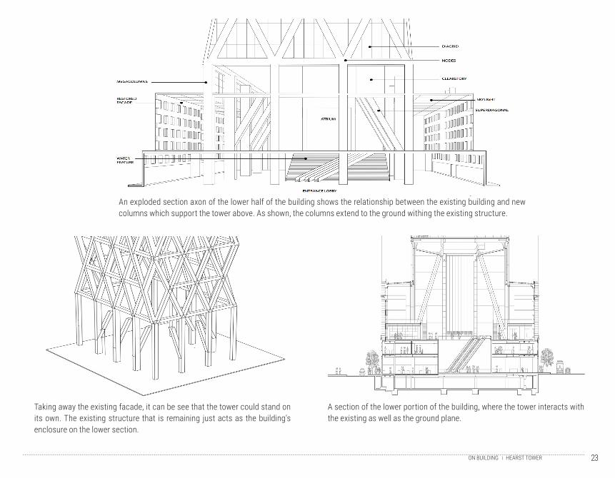
An exploded section axon of the lower half of the building shows the relationship between the existing building and new columns which support the tower above. As shown, the columns extend to the ground withing the existing structure.
Taking away the existing facade, it can be see that the tower could stand on its own. The existing structure that is remaining just acts as the building’s enclosure on the lower section.
A section of the lower portion of the building, where the tower interacts with the existing as well as the ground plane.
24 STOCK EXCHANGEON BUILDING
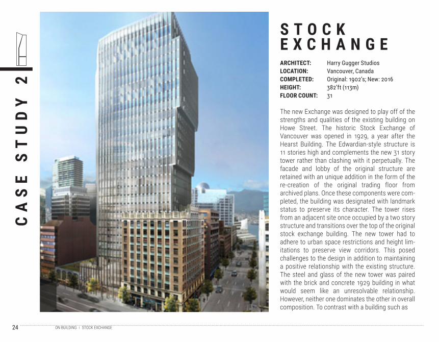
The new Exchange was designed to play off of the strengths and qualities of the existing building on Howe Street. The historic Stock Exchange of Vancouver was opened in 1929, a year after the Hearst Building. The Edwardian-style structure is 11 stories high and complements the new 31 story tower rather than clashing with it perpetually. The facade and lobby of the original structure are retained with an unique addition in the form of the re-creation of the original trading floor from archived plans. Once these components were com-pleted, the building was designated with landmark status to preserve its character. The tower rises from an adjacent site once occupied by a two story structure and transitions over the top of the original stock exchange building. The new tower had to adhere to urban space restrictions and height lim-itations to preserve view corridors. This posed challenges to the design in addition to maintaining a positive relationship with the existing structure. The steel and glass of the new tower was paired with the brick and concrete 1929 building in what would seem like an unresolvable relationship. However, neither one dominates the other in overall composition. To contrast with a building such as
CA
SE
ST
UD
Y 2
S T O C KE X C H A N G EARCHITECT:LOCATION:COMPLETED:HEIGHT:FLOOR COUNT:
Harry Gugger StudiosVancouver, CanadaOriginal: 1902’s; New: 2016382’ft (113m)31
25STOCK EXCHANGE`
the Hearst Tower where the original building was emptied, the floor area of the Exchange’s existing structure is integrated into the new tower. While the Stock Exchange is not strictly for office space, it includes a mixture of ground level retail in an effort to boost the vibrancy of downtown Vancouver. The tower is to be completed in 2017. This building serves as a case study for the adaptive re-use of an existing landmark to improve the performance of a new intervention.
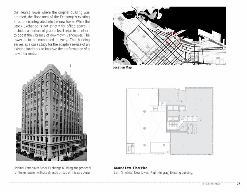
Location Map
Ground Level Floor Plan Left: (in white) New tower. Right (in gray) Existing building.
Original Vancouver Stock Exchange building; the proposal for the extension will site directly on top of this structure.
26 STOCK EXCHANGEON BUILDING
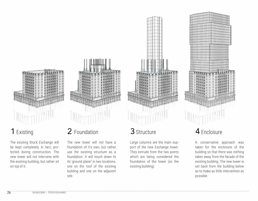
The existing Stock Exchange will be kept completely in tact, pro-tected during construction. The new tower will not intervene with the existing building, but rather sit on top of it.
The new tower will not have a foundation of it’s own, but rather use the existing structure as a foundation. It will touch down to its ‘ground plane” in two locations, one on the roof of the existing building and one on the adjacent site.
Large columns are the main sup-port of the new Exchange tower. They extrude from the two points which are being considered the foundation of the tower (on the existing building).
A conservative approach was taken for the enclosure of the building so that there was nothing taken away from the facade of the existing building. The new tower is set back from the building below as to make as little intervention as possible.
1 2 3 4Existing Foundation Structure Enclosure
27STOCK EXCHANGEON BUILDING
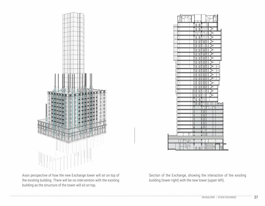
Axon perspective of how the new Exchange tower will sit on top of the existing building. There will be no intervention with the existing building as the structure of the tower will sit on top.
Section of the Exchange, showing the interaction of the existing building (lower right) with the new tower (upper left).
28
29ON WATERGROUND CONDITIONS
W A T E RCREATING FOUNDATIONS ON WATER
ON2.2
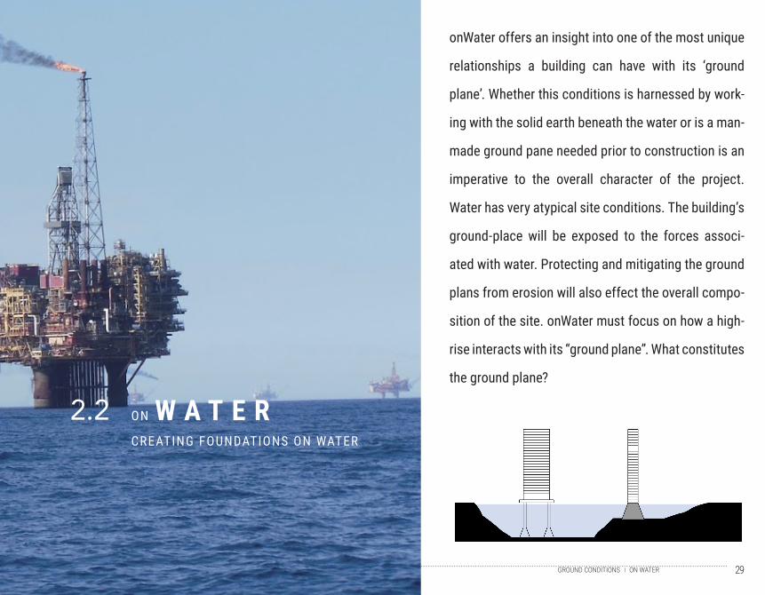
onWater offers an insight into one of the most unique
relationships a building can have with its ‘ground
plane’. Whether this conditions is harnessed by work-
ing with the solid earth beneath the water or is a man-
made ground pane needed prior to construction is an
imperative to the overall character of the project.
Water has very atypical site conditions. The building’s
ground-place will be exposed to the forces associ-
ated with water. Protecting and mitigating the ground
plans from erosion will also effect the overall compo-
sition of the site. onWater must focus on how a high-
rise interacts with its “ground plane”. What constitutes
the ground plane?
30 TIMELINEON WATER
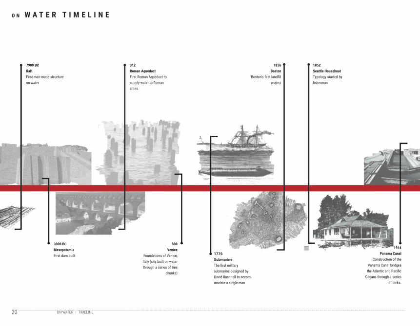
O N W A T E R T I M E L I N E
7989 BCRaftFirst man-made structure on water
3000 BCMesopotamiaFirst dam built
500Venice
Foundations of Venice, Italy (city built on water through a series of tree
chunks)
1776SubmarineThe first military submarine designed by David Bushnell to accom-modate a single man
1914Panama Canal
Construction of the Panama Canal bridges
the Atlantic and Pacific Oceans through a series
of locks.
312Roman AqueductFirst Roman Aqueduct to supply water to Roman cities.
1836Boston
Boston’s first landfill project
1852Seattle HouseboatTypology started by fisherman
31TIMELINEON WATER
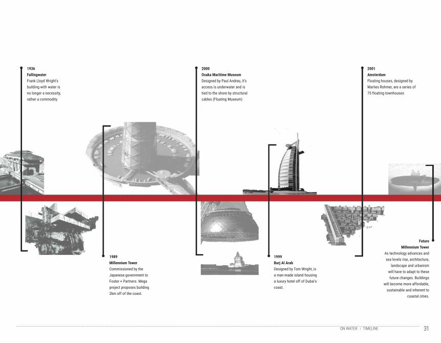
1989Millennium TowerCommissioned by the Japanese government to Foster + Partners. Mega project proposes building 2km off of the coast.
1999Burj Al ArabDesigned by Tom Wright, is a man-made island housing a luxury hotel off of Dubai’s coast.
FutureMillennium Tower
As technology advances and sea levels rise, architecture,
landscape and urbanism will have to adapt to these future changes. Buildings
will become more affordable, sustainable and inherent to
coastal cities.
1936FallingwaterFrank Lloyd Wright’s building with water is no longer a necessity, rather a commodity
2000Osaka Maritime MuseumDesigned by Paul Andreu, it’s access is underwater and is tied to the shore by structural cables (Floating Museum)
2001AmsterdamFloating houses, designed by Marlies Rohmer, are a series of 75 floating townhouses
32
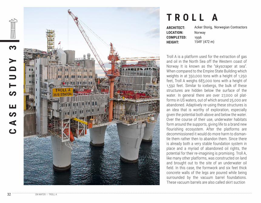
Troll A is a platform used for the extraction of gas and oil in the North Sea off the Western coast of Norway It is known as the “skyscraper at sea”. When compared to the Empire State Building which weights in at 350,000 tons with a height of 1,250 feet, Troll A weighs 683,000 tons with a height of 1,592 feet. Similar to icebergs, the bulk of these structures are hidden below the surface of the water. In general there are over 27,000 oil plat-forms in US waters, out of which around 25,000 are abandoned. Adaptively re-using these structures is an idea that is worthy of exploration, especially given the potential both above and below the water. Over the course of their use, underwater habitats form around the supports, giving life to a brand new flourishing ecosystem. After the platforms are decommissioned it would do more harm to disman-tle them rather then to abandon them. Since there is already both a very stable foundation system in place and a myriad of abandoned oil rights, the potential for their re-imagining is promising. Troll A, like many other platforms, was constructed on land and brought out to the site of an underwater oil field. In this case, the formwork and six feet thick concrete walls of the legs are poured while being surrounded by the vacuum barrel foundations. These vacuum barrels are also called skirt suction
CA
SE
ST
UD
Y 3
T R O L L AARCHITECT:LOCATION:COMPLETED:HEIGHT:
Acker Storig, Norwegian ContractorsNorway19961549’ (472 m)
TROLL AON WATER
33
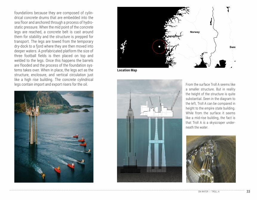
foundations because they are composed of cylin-drical concrete drums that are embedded into the sea floor and anchored through a process of hydro-static pressure. When the mid point of the concrete legs are reached, a concrete belt is cast around them for stability and the structure is prepped for transport. The legs are towed from the temporary dry-dock to a fjord where they are then moved into deeper waters. A prefabricated platform the size of three football fields is then placed on top and welded to the legs. Once this happens the barrels are flooded and the process of the foundation sys-tems takes over. When in place, the legs act as the structure, enclosure, and vertical circulation just like a high rise building. The concrete cylindrical legs contain import and export risers for the oil. From the surface Troll A seems like
a smaller structure. But in reality the height of the structure is quite substantial. Seen in the diagram to the left, Troll A can be compared in height to the empire state building. While from the surface it seems like a mid-rise building, the fact is that Troll A is a skyscraper under-neath the water.
Location Map
TROLL AON WATER
34
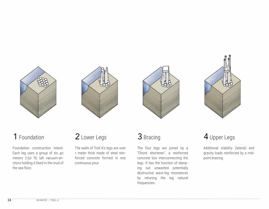
Foundation construction inland. Each leg uses a group of six 40 meters (130 ft) tall vacuum-an-chors holding it fixed in the mud of the sea floor.
The walls of Troll A’s legs are over 1 meter thick made of steel rein-forced concrete formed in one continuous pour.
The four legs are joined by a “Chord shortener”, a reinforced concrete box interconnecting the legs. It has the function of damp-ing out unwanted potentially destructive wave-leg resonances by retuning the leg natural frequencies.
Additional stability (lateral) and gravity loads reinforced by a mid-point bracing.
1 2 3 4Foundation Lower Legs Bracing Upper Legs
TROLL AON WATER
35
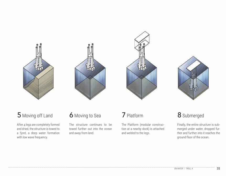
After 4 legs are completely formed and dried, the structure is towed to a fjord, a deep water formation with low wave frequency.
The structure continues to be towed further out into the ocean and away from land.
The Platform (modular construc-tion at a nearby dock) is attached and welded to the legs.
Finally, the entire structure is sub-merged under water, dropped fur-ther and further into it reaches the ground floor of the ocean.
5 6 7 8Moving off Land Moving to Sea Platform Submerged
TROLL AON WATER
36
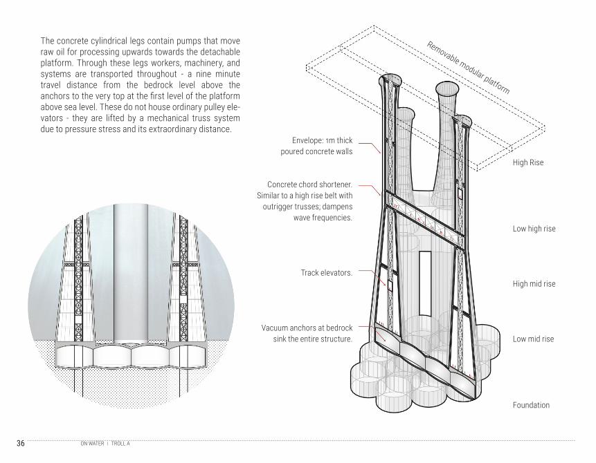
Envelope: 1m thick poured concrete walls
Concrete chord shortener. Similar to a high rise belt with
outrigger trusses; dampens wave frequencies.
Track elevators.
Vacuum anchors at bedrock sink the entire structure.
Foundation
Low mid rise
High mid rise
Low high rise
High Rise
Removable modular platform
The concrete cylindrical legs contain pumps that move raw oil for processing upwards towards the detachable platform. Through these legs workers, machinery, and systems are transported throughout - a nine minute travel distance from the bedrock level above the anchors to the very top at the first level of the platform above sea level. These do not house ordinary pulley ele-vators - they are lifted by a mechanical truss system due to pressure stress and its extraordinary distance.
TROLL AON WATER
37
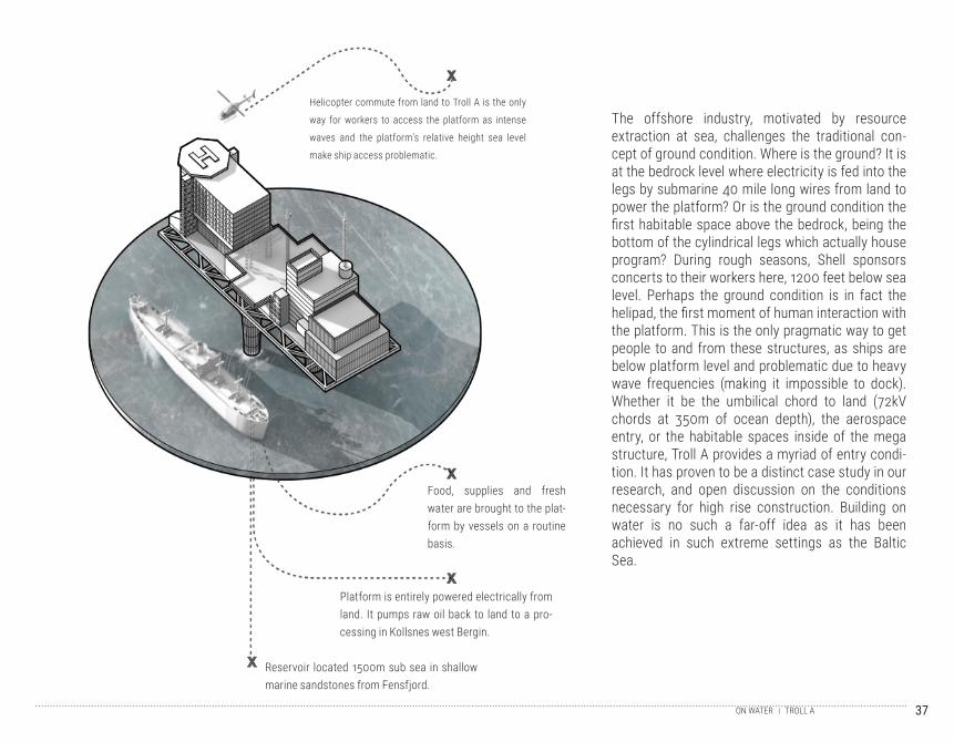
The offshore industry, motivated by resource extraction at sea, challenges the traditional con-cept of ground condition. Where is the ground? It is at the bedrock level where electricity is fed into the legs by submarine 40 mile long wires from land to power the platform? Or is the ground condition the first habitable space above the bedrock, being the bottom of the cylindrical legs which actually house program? During rough seasons, Shell sponsors concerts to their workers here, 1200 feet below sea level. Perhaps the ground condition is in fact the helipad, the first moment of human interaction with the platform. This is the only pragmatic way to get people to and from these structures, as ships are below platform level and problematic due to heavy wave frequencies (making it impossible to dock). Whether it be the umbilical chord to land (72kV chords at 350m of ocean depth), the aerospace entry, or the habitable spaces inside of the mega structure, Troll A provides a myriad of entry condi-tion. It has proven to be a distinct case study in our research, and open discussion on the conditions necessary for high rise construction. Building on water is no such a far-off idea as it has been achieved in such extreme settings as the Baltic Sea.
Helicopter commute from land to Troll A is the only
way for workers to access the platform as intense
waves and the platform’s relative height sea level
make ship access problematic.
Food, supplies and fresh water are brought to the plat-form by vessels on a routine basis.
Reservoir located 1500m sub sea in shallow marine sandstones from Fensfjord.
Platform is entirely powered electrically from land. It pumps raw oil back to land to a pro-cessing in Kollsnes west Bergin.
TROLL AON WATER
38
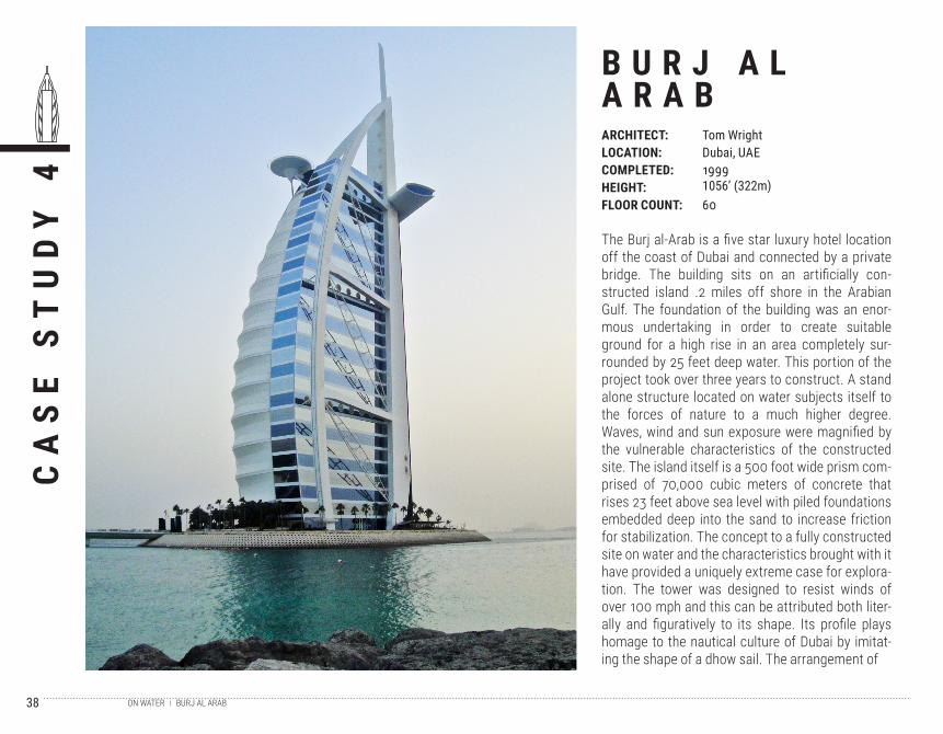
The Burj al-Arab is a five star luxury hotel location off the coast of Dubai and connected by a private bridge. The building sits on an artificially con-structed island .2 miles off shore in the Arabian Gulf. The foundation of the building was an enor-mous undertaking in order to create suitable ground for a high rise in an area completely sur-rounded by 25 feet deep water. This portion of the project took over three years to construct. A stand alone structure located on water subjects itself to the forces of nature to a much higher degree. Waves, wind and sun exposure were magnified by the vulnerable characteristics of the constructed site. The island itself is a 500 foot wide prism com-prised of 70,000 cubic meters of concrete that rises 23 feet above sea level with piled foundations embedded deep into the sand to increase friction for stabilization. The concept to a fully constructed site on water and the characteristics brought with it have provided a uniquely extreme case for explora-tion. The tower was designed to resist winds of over 100 mph and this can be attributed both liter-ally and figuratively to its shape. Its profile plays homage to the nautical culture of Dubai by imitat-ing the shape of a dhow sail. The arrangement of
CA
SE
ST
UD
Y 4
B U R J A LA R A BARCHITECT:LOCATION:COMPLETED:HEIGHT:FLOOR COUNT:
Tom WrightDubai, UAE19991056’ (322m)60
BURJ AL ARABON WATER
39
the Burj al-Arab is a “V” shaped plan with three cores, one at each point. These cores contain all of the services including elevators and egress. The structure of the ‘V’ also assists in bracing against the wind conditions by including tensile, tubular steel trusses that from the outer sides. Each truss is the size of an airbus’s fuselage. In addition to the potentially extreme wind conditions, corrosion from the salty sea was a particular concern that had to be addressed in the material choices as a fact of building on a site bounded by water. To pro-tect the island from erosion, a perimeter of con-crete blocks with voids resembling a honeycomb shape were installed allowing the edge to act as a sponge to mitigate the ebbs and flows of water The tower also opens itself up to full sun exposure, which given Dubai’s location in a area of extreme temperate fluctuation had to be considered with shading and cooling strategies.
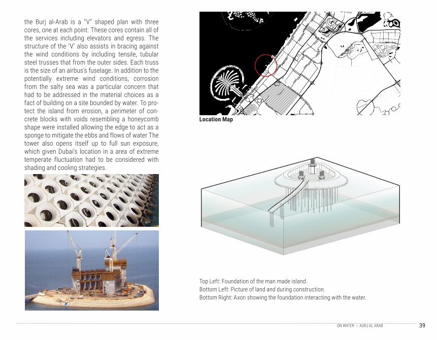
Location Map
Top Left: Foundation of the man made island.Bottom Left: Picture of land and during construction. Bottom Right: Axon showing the foundation interacting with the water.
AURJ AL ARABON WATER
40
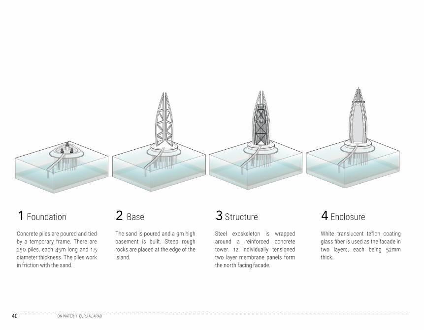
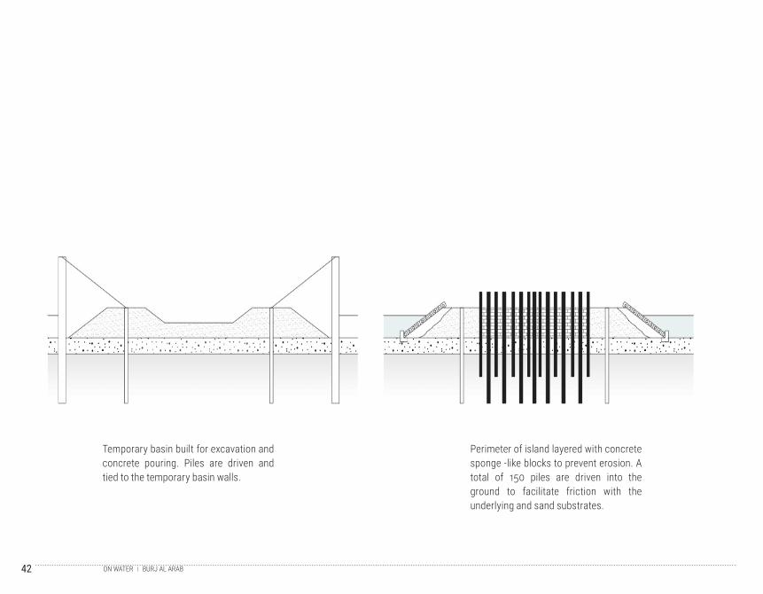
Concrete piles are poured and tied by a temporary frame. There are 250 piles, each 45m long and 1.5 diameter thickness. The piles work in friction with the sand.
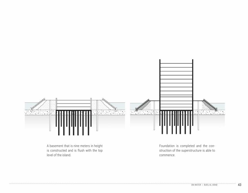
The sand is poured and a 9m high basement is built. Steep rough rocks are placed at the edge of the island.
Steel exoskeleton is wrapped around a reinforced concrete tower. 12 Individually tensioned two layer membrane panels form the north facing facade.
White translucent teflon coating glass fiber is used as the facade in two layers, each being 52mm thick.
1 2 3 4Foundation Base Structure Enclosure
BURJ AL ARABON WATER
41
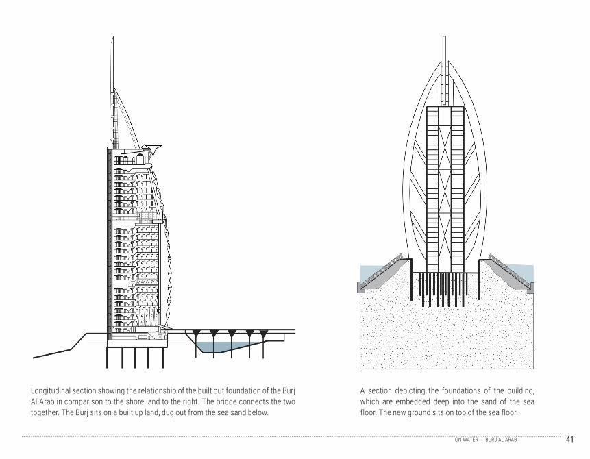
Longitudinal section showing the relationship of the built out foundation of the Burj Al Arab in comparison to the shore land to the right. The bridge connects the two together. The Burj sits on a built up land, dug out from the sea sand below.
A section depicting the foundations of the building, which are embedded deep into the sand of the sea floor. The new ground sits on top of the sea floor.
BURJ AL ARABON WATER
42
Temporary basin built for excavation and concrete pouring. Piles are driven and tied to the temporary basin walls.
Perimeter of island layered with concrete sponge -like blocks to prevent erosion. A total of 150 piles are driven into the ground to facilitate friction with the underlying and sand substrates.
BURJ AL ARABON WATER
43
A basement that is nine meters in height is constructed and is flush with the top level of the island.
Foundation is completed and the con-struction of the superstructure is able to commence.
BURJ AL ARABON WATER
44
45
T E R R A I NBUILDING ON EXTREME TOPOGRAPHY
ON2.3
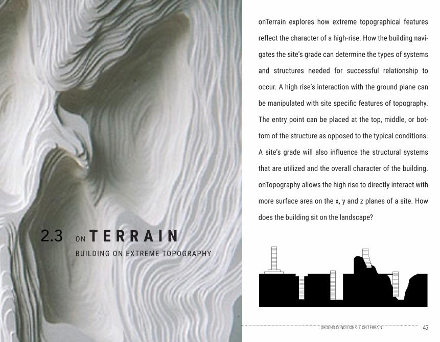
onTerrain explores how extreme topographical features
reflect the character of a high-rise. How the building navi-
gates the site’s grade can determine the types of systems
and structures needed for successful relationship to
occur. A high rise’s interaction with the ground plane can
be manipulated with site specific features of topography.
The entry point can be placed at the top, middle, or bot-
tom of the structure as opposed to the typical conditions.
A site’s grade will also influence the structural systems
that are utilized and the overall character of the building.
onTopography allows the high rise to directly interact with
more surface area on the x, y and z planes of a site. How
does the building sit on the landscape?
ON TERRAINGROUND CONDITIONS
46
O N T O P O G R A P H Y T I M E L I N E
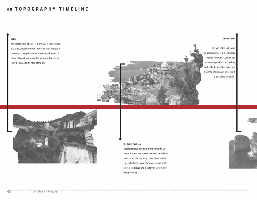
Kotor
The coastal town of Kotor is a UNESCO world heritage
site. Undoubtedly, it served the designation because of
the majestic rugged mountains towering all around it
with a ribbon of blue water that somehow finds its way
from the ocean to the edge of the city
St. John’s Fortress
Another famous landmark of the city is the St.
John’s Fortress that towers overhead carved into
and at other places jutting out of the mountain.
This Kotor fortress is a prominent feature of the
present landscape and the story of Montenegro
through history.
Fortress Wall
The wall of the fortress is
free-standing until it tucks naturally
into the mountain. Cut from the
surrounding rock and masterfully
built, it looks like it has been here
since the beginning of time–like it
is part of the mountain.
TIMELINEON TERRAIN
47
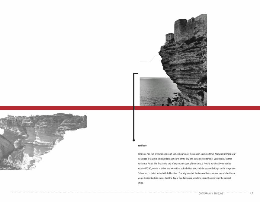
Bonifacio
Bonifacio has two prehistoric sites of some importance: the ancient cave shelter of Araguina-Sennola near
the village of Capello on Route N96 just north of the city and a chambered tomb of Vasculacciu further
north near Figari. The first is the site of the notable Lady of Bonifacio, a female burial carbon-dated to
about 6570 BC, which is either late Mesolithic or Early Neolithic, and the second belongs to the Megalithic
Culture and is dated to the Middle Neolithic. The alignment of the two and the extensive use of chert from
Monte Arci in Sardinia shows that the Bay of Bonifacio was a route to inland Corsica from the earliest
times.
TIMELINEON TERRAIN
48
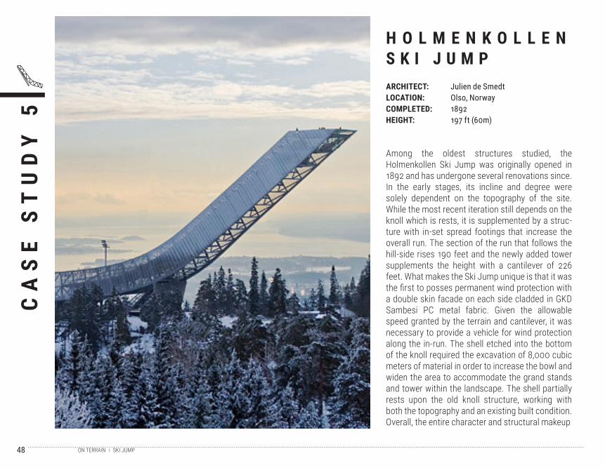
Among the oldest structures studied, the Holmenkollen Ski Jump was originally opened in 1892 and has undergone several renovations since. In the early stages, its incline and degree were solely dependent on the topography of the site. While the most recent iteration still depends on the knoll which is rests, it is supplemented by a struc-ture with in-set spread footings that increase the overall run. The section of the run that follows the hill-side rises 190 feet and the newly added tower supplements the height with a cantilever of 226 feet. What makes the Ski Jump unique is that it was the first to posses permanent wind protection with a double skin facade on each side cladded in GKD Sambesi PC metal fabric. Given the allowable speed granted by the terrain and cantilever, it was necessary to provide a vehicle for wind protection along the in-run. The shell etched into the bottom of the knoll required the excavation of 8,000 cubic meters of material in order to increase the bowl and widen the area to accommodate the grand stands and tower within the landscape. The shell partially rests upon the old knoll structure, working with both the topography and an existing built condition. Overall, the entire character and structural makeup
CA
SE
ST
UD
Y 5
H O L M E N K O L L E N S K I J U M PARCHITECT:LOCATION:COMPLETED:HEIGHT:
Julien de SmedtOlso, Norway1892197 ft (60m)
SKI JUMPON TERRAIN
49
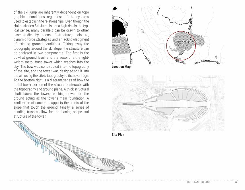
of the ski jump are inherently dependent on topo graphical conditions regardless of the systems used to establish the relationships. Even though the Holmenkollen Ski Jump is not a high rise in the typ-ical sense, many parallels can be drawn to other case studies by means of structure, enclosure, dynamic force strategies and an acknowledgment of existing ground conditions. Taking away the topography around the ski slope, the structure can be analyzed in two components. The first is the bowl at ground level, and the second is the light-weight metal truss tower which reaches into the sky. The bow was constructed into the topography of the site, and the tower was designed to tilt into the air, using the site’s topography to its advantage. To the bottom right is a diagram series of how the metal tower portion of the structure interacts with the topography and ground plane. A thick structural shaft backs the tower, reaching down into the ground acting as the tower’s main foundation. A knoll made of concrete supports the points of the slope that touch the ground. Finally, a series of bending trusses allow for the leaning shape and structure of the tower.
Location Map
Site Plan
SKI JUMPON TERRAIN
50
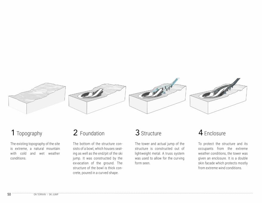
The existing topography of the site is extreme, a natural mountain with cold and wet weather conditions.
The bottom of the structure con-sists of a bowl, which houses seat-ing as well as the end/pit of the ski jump. It was constructed by the exvacation of the ground. The structure of the bowl is thick con-crete, poured in a curved shape.
The tower and actual jump of the structure is constructed out of lightweight metal. A truss system was used to allow for the curving form seen.
To protect the structure and its occupants from the extreme weather conditions, the tower was given an enclosure. It is a double skin facade which protects mostly from extreme wind conditions.
1 2 3 4Topography Foundation Structure Enclosure
SKI JUMPON TERRAIN

51
Right: Detailed axon of the main structural com-ponents interacting with the ground and sloped conditions. A large shaft acts as the spine of the building, allowing for the tower portion to reach into the air. The knoll at the bottom of the shaft acts as a large foundation for the structure. Further down the structure are columns attached to a metal plate, which support the curved part of the structure.
Bottom: A complete section of the structure, showing the truss tower and bowl below. Here the extreme topographic changes between the top of the tower and the bottom of the bowl can be seen. The large shaft, knoll and smaller columns all together allow the structure to take the curved and leaning form that can be seen.
SKI JUMPON TERRAIN
52
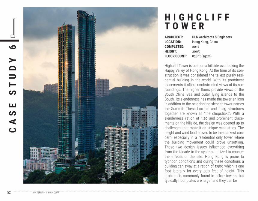
Highcliff Tower is built on a hillside overlooking the Happy Valley of Hong Kong. At the time of its con-struction it was considered the tallest purely resi-dential building in the world. With its prominent placements it offers unobstructed views of its sur-roundings. The higher floors provide views of the South China Sea and outer lying islands to the South. Its slenderness has made the tower an icon in addition to the neighboring slender tower names the Summit. These two tall and thing structures together are known as “the chopsticks”. With a slenderness ration of 1:20 and prominent place-ments on the hillside, the design was opened up to challenges that make it an unique case study. The height and wind load proved to be the starkest con-cern, especially in a residential only tower where the building movement could prove unsettling. These two design issues influenced everything from the facade to the systems utilized to counter the effects of the site. Hong Kong is prone to typhoon conditions and during these conditions a building can sway at a ration of 1:500 which is one foot laterally for every 500 feet of height. This problem is commonly found in office towers, but typically floor plates are larger and they can be
CA
SE
ST
UD
Y 6
H I G H C L I F FT O W E RARCHITECT:LOCATION:COMPLETED:HEIGHT:FLOOR COUNT:
DLN Architects & EngineersHong Kong, China20122003828 ft (252m)
HIGH CLIFFON TERRAIN
53
unoccupied during bad weather conditions. The opposite of both are true in the case of Highcliff, and its prominent point on the hillside only further exposes it to these conditions. Without any sup-porting systems, the cycle of a sway could last up to nine seconds. To avoid creating a system with massive columns to address this issue, damper tank system that was both passive and mainte-nance free was implemented. This system features water tanks in layers and compartments organized in a grid form with strategically placed openings allowing the flow of water to automatically counter the wind load. The movement rate with this system was reduced from nine seconds of discomfort to a manageable 4.7 seconds.
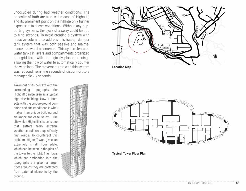
Taken out of its context with the surrounding topography, the Highcliff can be seen as a typical high rise building. How it inter-acts with the unique ground con-dition and site conditions is what makes it an unique building and an important case study. The site which Highcliff sits on is one that suffers from extreme weather conditions, specifically high winds. To counteract this problem, Highciff was given an extremely small floor plate, which can be seen in the plan of the tower to the right. The floors which are embedded into the topography are given a larger floor area, as they are protected from external elements by the ground.
Location Map
Typical Tower Floor Plan
HIGH CLIFFON TERRAIN
54
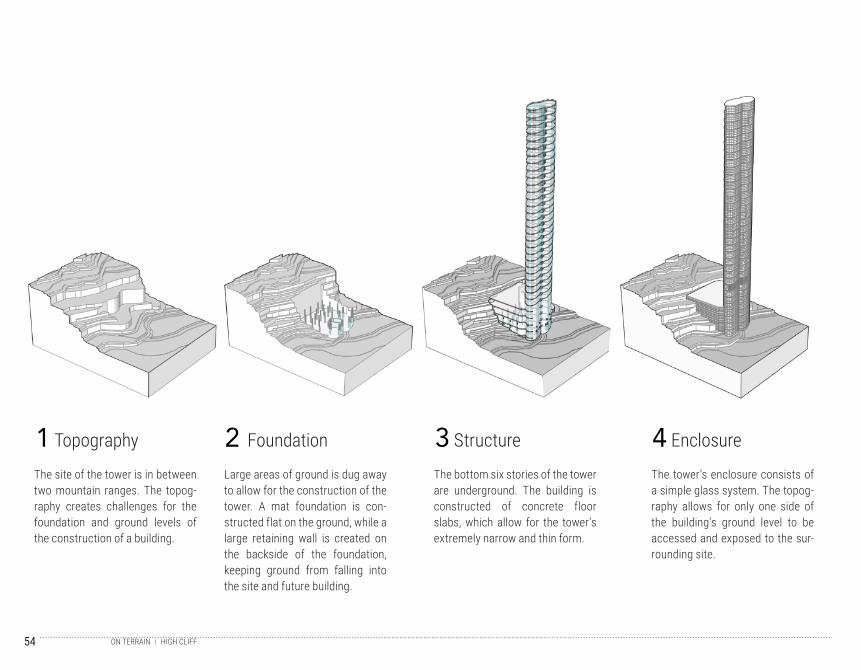
The site of the tower is in between two mountain ranges. The topog-raphy creates challenges for the foundation and ground levels of the construction of a building.
Large areas of ground is dug away to allow for the construction of the tower. A mat foundation is con-structed flat on the ground, while a large retaining wall is created on the backside of the foundation, keeping ground from falling into the site and future building.
The bottom six stories of the tower are underground. The building is constructed of concrete floor slabs, which allow for the tower’s extremely narrow and thin form.
The tower’s enclosure consists of a simple glass system. The topog-raphy allows for only one side of the building’s ground level to be accessed and exposed to the sur-rounding site.
1 2 3 4Topography Foundation Structure Enclosure
HIGH CLIFFON TERRAIN
55
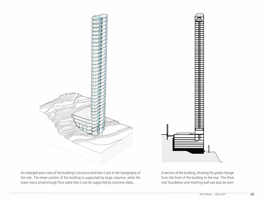
An enlarged axon view of the building’s structure and how it sits in the topography of the site. The lower portion of the building is supported by large columns, while the tower has a small enough floor plate that it can be supported by concrete slabs.
A section of the building, showing the grade change from the front of the building to the rear. The thick mat foundation and retaining wall can also be seen
HIGH CLIFFON TERRAIN
56
57
I N F R A S T R U C T U R EBUILDING OVER RAILWAYS
OVER
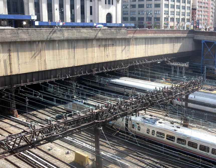
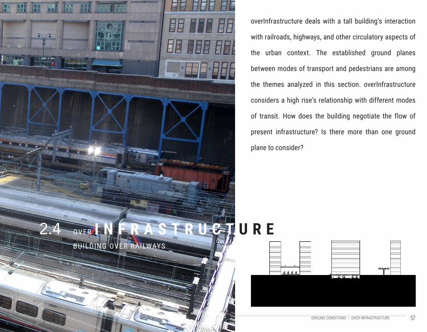
overInfrastructure deals with a tall building’s interaction
with railroads, highways, and other circulatory aspects of
the urban context. The established ground planes
between modes of transport and pedestrians are among
the themes analyzed in this section. overInfrastructure
considers a high rise’s relationship with different modes
of transit. How does the building negotiate the flow of
present infrastructure? Is there more than one ground
plane to consider?
2.4
OVER INFRASTRUCTUREGROUND CONDITIONS
58
O V E R I N F R A S T R U C T U R E T I M E L I N E
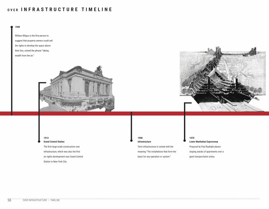
1908
William Wilgus is the first person to
suggest that property owners could sell
the rights to develop the space above
their lots, coined the phrase “taking
wealth from the air.”
1913Grand Central Station
The first large-scale construction over
infrastructure, which was also the first
air rights development was Grand Central
Station in New York City.
1908Infrastructure
Term infrastructure is coined with the
meaning “The installations that form the
basis for any operation or system.”
1970Lower Manhattan Expressway
Proposal by Paul Rudolph places
sloping stacks of apartments over a
giant transportation artery.
TIMELINEOVER INFRASTRUCTURE
59
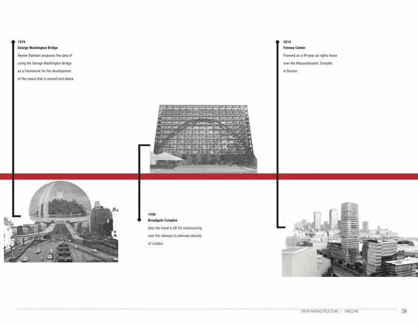
1976George Washington Bridge
Reyner Banham proposes the idea of
using the George Washington Bridge
as a framework for the development
of the space that is around and above
2014Fenway Center
Planned on a 99-year air rights lease
over the Massachusetts Turnpike
in Boston
1990Broadgate Complex
Sets the trend in UK for constructing
over the railways to alleviate density
of London
TIMELINEOVER INFRASTRUCTURE
60
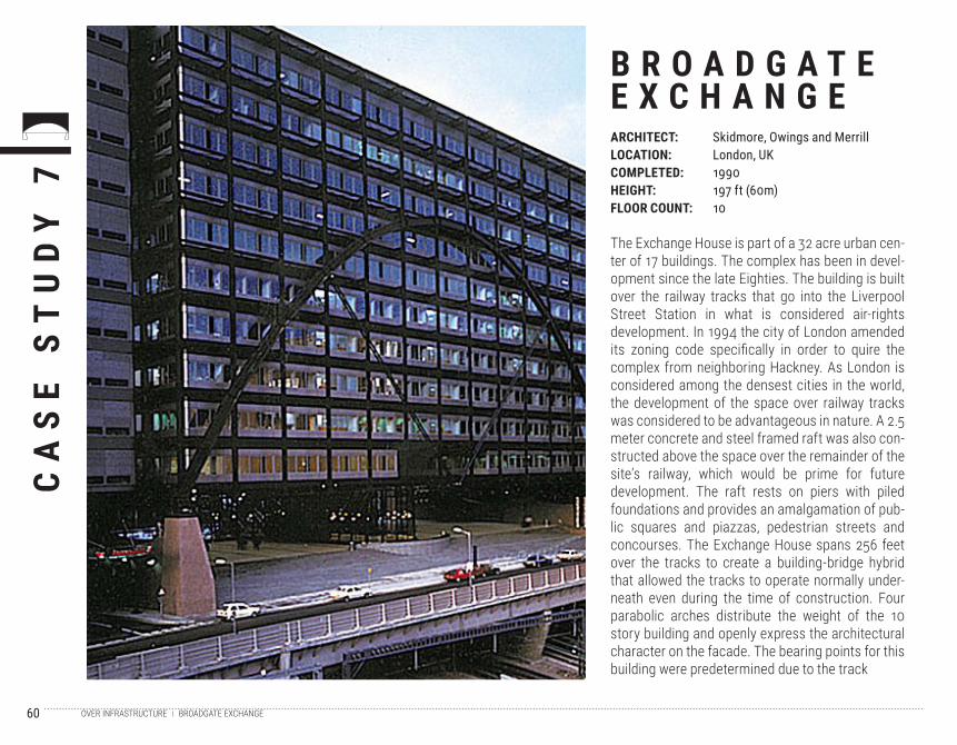
The Exchange House is part of a 32 acre urban cen-ter of 17 buildings. The complex has been in devel-opment since the late Eighties. The building is built over the railway tracks that go into the Liverpool Street Station in what is considered air-rights development. In 1994 the city of London amended its zoning code specifically in order to quire the complex from neighboring Hackney. As London is considered among the densest cities in the world, the development of the space over railway tracks was considered to be advantageous in nature. A 2.5 meter concrete and steel framed raft was also con-structed above the space over the remainder of the site’s railway, which would be prime for future development. The raft rests on piers with piled foundations and provides an amalgamation of pub-lic squares and piazzas, pedestrian streets and concourses. The Exchange House spans 256 feet over the tracks to create a building-bridge hybrid that allowed the tracks to operate normally under-neath even during the time of construction. Four parabolic arches distribute the weight of the 10 story building and openly express the architectural character on the facade. The bearing points for this building were predetermined due to the track
CA
SE
ST
UD
Y 7
B R O A D G A T EE X C H A N G EARCHITECT:LOCATION:COMPLETED:HEIGHT:FLOOR COUNT:
Skidmore, Owings and MerrillLondon, UK1990197 ft (60m)10
BROADGATE EXCHANGEOVER INFRASTRUCTURE
61
arrangement, but that did not necessarily reflect a limitation. The infrastructure was embraced to for-mulate the arrangement and character of both the building and the site. The Exchange House pre-pared for future development with the construction of the raft. With it came an extended ground plane from the street through the underside of the build-ing to the plaza for public use. The Exchange House negotiated different scales of traffic and access by being both elevated over the tracks and lifted an additional level off of the street. This allowed the existing infrastructure to routinely function below the raft and pedestrian traffic from the street to the public plaza to occur above the raft.
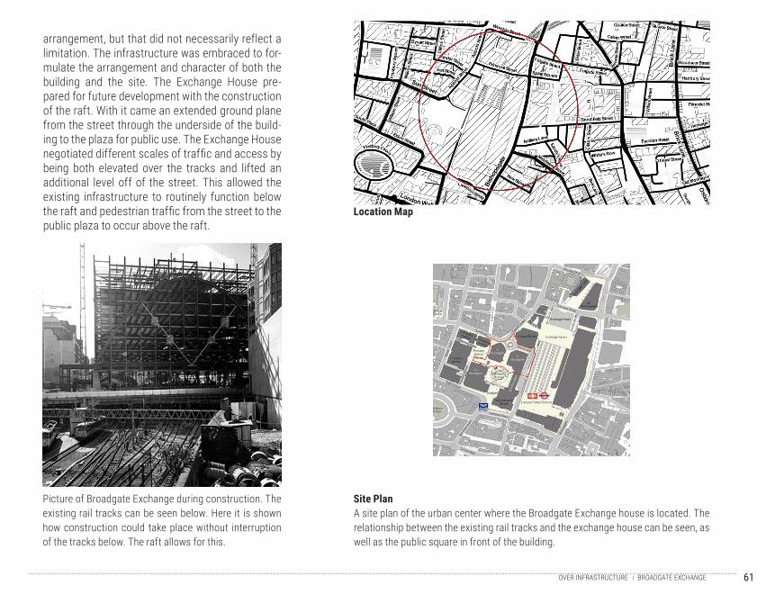
A site plan of the urban center where the Broadgate Exchange house is located. The relationship between the existing rail tracks and the exchange house can be seen, as well as the public square in front of the building.
Picture of Broadgate Exchange during construction. The existing rail tracks can be seen below. Here it is shown how construction could take place without interruption of the tracks below. The raft allows for this.
Location Map
Site Plan
BROADGATE EXCHANGEOVER INFRASTRUCTURE
62
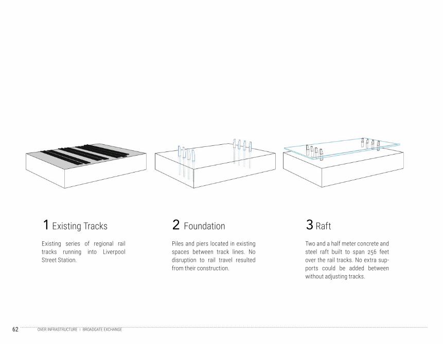
Existing series of regional rail tracks running into Liverpool Street Station.
Piles and piers located in existing spaces between track lines. No disruption to rail travel resulted from their construction.
Two and a half meter concrete and steel raft built to span 256 feet over the rail tracks. No extra sup-ports could be added between without adjusting tracks.
1 2 3Existing Tracks Foundation Raft
BROADGATE EXCHANGEOVER INFRASTRUCTURE
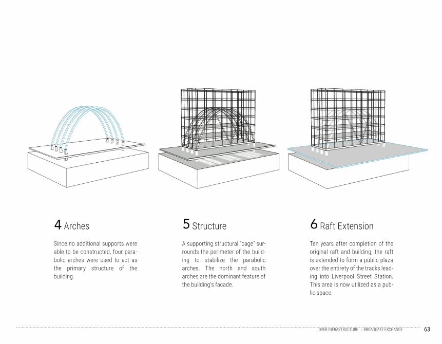
63
Since no additional supports were able to be constructed, four para-bolic arches were used to act as the primary structure of the building.
4 Arches
A supporting structural “cage” sur-rounds the perimeter of the build-ing to stabilize the parabolic arches. The north and south arches are the dominant feature of the building’s facade.
5 Structure
Ten years after completion of the original raft and building, the raft is extended to form a public plaza over the entirety of the tracks lead-ing into Liverpool Street Station. This area is now utilized as a pub-lic space.
6 Raft Extension
BROADGATE EXCHANGEOVER INFRASTRUCTURE
64
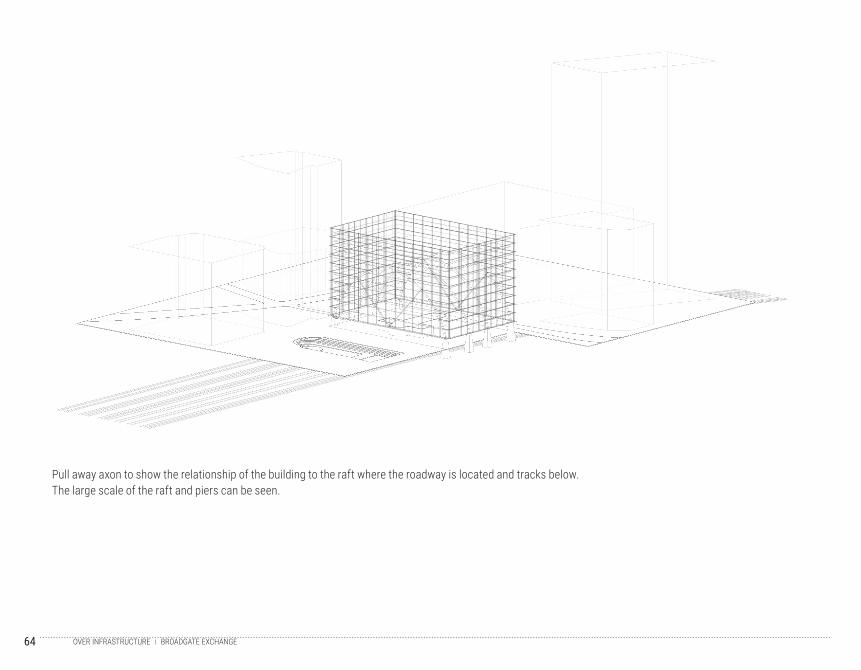
Pull away axon to show the relationship of the building to the raft where the roadway is located and tracks below. The large scale of the raft and piers can be seen.
BROADGATE EXCHANGEOVER INFRASTRUCTURE
65
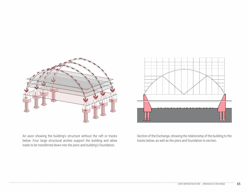
Section of the Exchange, showing the relationship of the building to the tracks below, as well as the piers and foundation in section.
An axon showing the building’s structure without the raft or tracks below. Four large structural arches support the building and allow loads to be transferred down into the piers and building’s foundation.
BROADGATE EXCHANGEOVER INFRASTRUCTURE
66
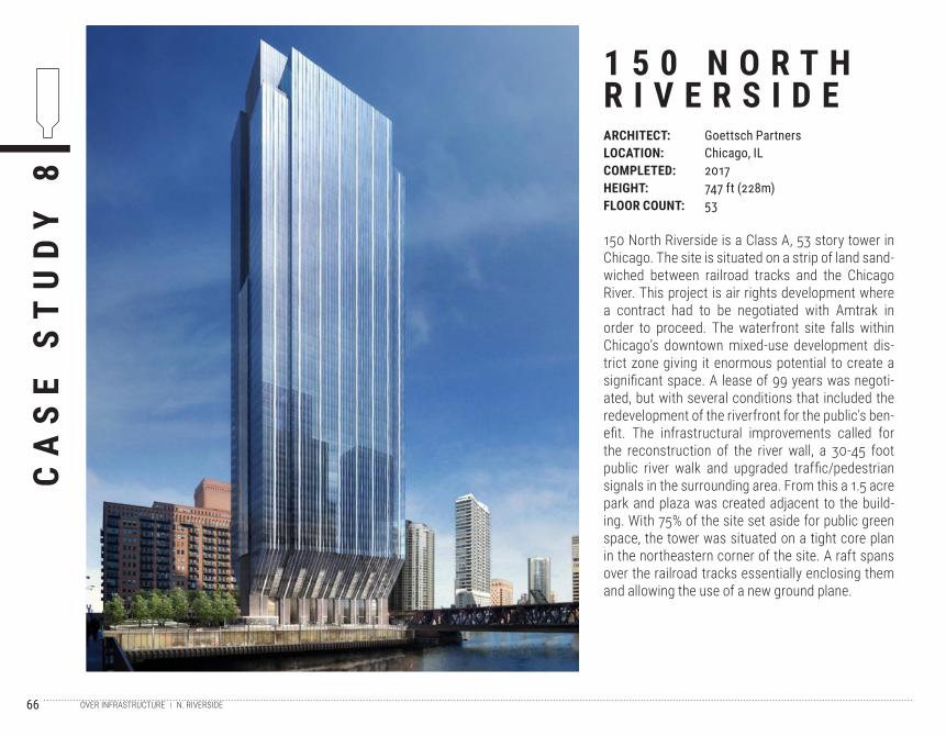
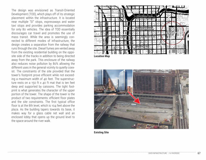
150 North Riverside is a Class A, 53 story tower in Chicago. The site is situated on a strip of land sand-wiched between railroad tracks and the Chicago River. This project is air rights development where a contract had to be negotiated with Amtrak in order to proceed. The waterfront site falls within Chicago’s downtown mixed-use development dis-trict zone giving it enormous potential to create a significant space. A lease of 99 years was negoti-ated, but with several conditions that included the redevelopment of the riverfront for the public’s ben-efit. The infrastructural improvements called for the reconstruction of the river wall, a 30-45 foot public river walk and upgraded traffic/pedestrian signals in the surrounding area. From this a 1.5 acre park and plaza was created adjacent to the build-ing. With 75% of the site set aside for public green space, the tower was situated on a tight core plan in the northeastern corner of the site. A raft spans over the railroad tracks essentially enclosing them and allowing the use of a new ground plane.
CA
SE
ST
UD
Y 8
1 5 0 N O R T HR I V E R S I D EARCHITECT:LOCATION:COMPLETED:HEIGHT:FLOOR COUNT:
Goettsch PartnersChicago, IL2017747 ft (228m)53
N. RIVERSIDE OVER INFRASTRUCTURE
67
The design was envisioned as Transit-Oriented Development (TOD), which plays off of its strategic placement within the infrastructure. It is located near multiple “El” stops, expressways and water taxi stops and provides parking accommodation for only 80 vehicles. The idea of TOD essentially discourages car travel and promotes the use of mass transit. While the area is seemingly con-nected to different modes of infrastructure, the design creates a separation from the railway that runs through the site. Diesel fumes are vented away from the existing residential building on the oppo-site side of the tracks in addition to being directed away from the park. This enclosure of the railway also reduces noise pollution by 80% allowing the different uses in the general vicinity to quietly coex-ist. The constraints of the site provided that the tower’s footprint prove efficient while not exceed-ing a maximum width of 40 feet. The superstruc-ture rests on a 150 ft x 40 ft mat that is ten feet deep and supported by caissons. The tight foot-print is what generates the character of the upper portion of the tower. The shape of the tower is the product of two requirements: efficient floor plates and the site constraints. The first typical office floor is at the 8th level, which is 104 feet above the plaza. As the building tapers towards its base, it makes way for a glass cable net wall and an enclosed lobby that opens up the ground level to the space around the river walk.
Location Map
Existing Site
N. RIVERSIDEOVER INFRASTRUCTURE
68
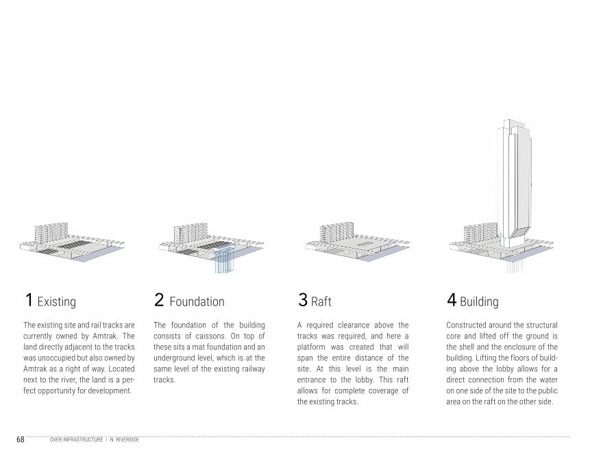
The existing site and rail tracks are currently owned by Amtrak. The land directly adjacent to the tracks was unoccupied but also owned by Amtrak as a right of way. Located next to the river, the land is a per-fect opportunity for development.
The foundation of the building consists of caissons. On top of these sits a mat foundation and an underground level, which is at the same level of the existing railway tracks.
A required clearance above the tracks was required, and here a platform was created that will span the entire distance of the site. At this level is the main entrance to the lobby. This raft allows for complete coverage of the existing tracks.
Constructed around the structural core and lifted off the ground is the shell and the enclosure of the building. Lifting the floors of build-ing above the lobby allows for a direct connection from the water on one side of the site to the public area on the raft on the other side.
1 2 3 4Existing Foundation Raft Building
N. RIVERSIDE OVER INFRASTRUCTURE
69
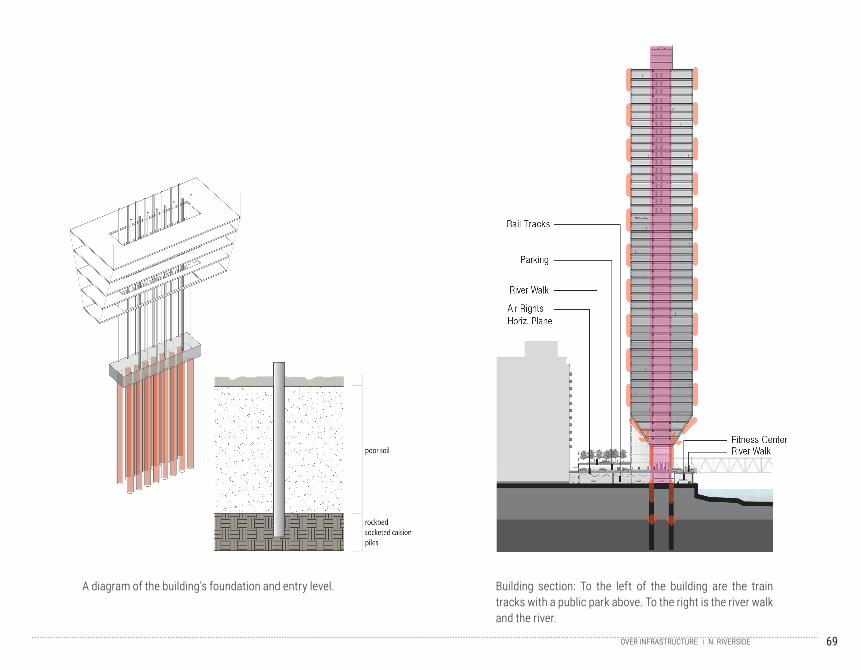
Building section: To the left of the building are the train tracks with a public park above. To the right is the river walk and the river.
A diagram of the building’s foundation and entry level.
N. RIVERSIDEOVER INFRASTRUCTURE

70
71
C O M P O N E N T S3
Components studies the pieces that go into the construction of a tall building. Within components there
are four subdivisions: foundations, structure, vertical circulation, and enclosure. These categories com-
bined are the components that allow a tall building to stand and function as a whole. Different systems
were analyzed and compared to gather the most holistic and complete understanding possible of the com-
ponents of tall buildings.
72
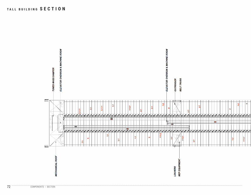
T A L L B U I L D I N G S E C T I O N
SECTIONCOMPONENTS
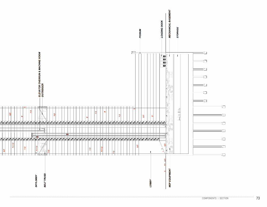
73SECTIONCOMPONENTS
74
75
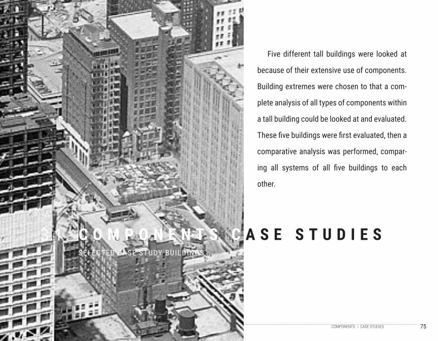
C O M P O N E N T S C A S E S T U D I E SSELECTED CASE STUDY BUILDINGS
3.1
Five different tall buildings were looked at
because of their extensive use of components.
Building extremes were chosen to that a com-
plete analysis of all types of components within
a tall building could be looked at and evaluated.
These five buildings were first evaluated, then a
comparative analysis was performed, compar-
ing all systems of all five buildings to each
other.
CASE STUDIESCOMPONENTS
76
CA
SE
ST
UD
Y 9
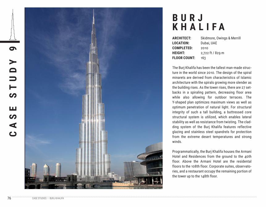
B U R J K H A L I F AARCHITECT:LOCATION:COMPLETED:HEIGHT:FLOOR COUNT:
Skidmore, Owings & MerrillDubai, UAE20102,722 ft / 829 m163
The Burj Khalifa has been the tallest man-made struc-ture in the world since 2010. The design of the spiral minarets are derived from characteristics of Islamic architecture with the spirals growing more slender as the building rises. As the tower rises, there are 27 set-backs in a spiraling pattern, decreasing floor area while also allowing for outdoor terraces. The Y-shaped plan optimizes maximum views as well as optimum penetration of natural light. For structural integrity of such a tall building, a buttressed core structural system is utilized, which enables lateral stability as well as resistance from twisting. The clad-ding system of the Burj Khalifa features reflective glazing and stainless steel spandrels for protection from the extreme desert temperatures and strong winds.
Programmatically, the Burj Khalifa houses the Armani Hotel and Residences from the ground to the 40th floor. Above the Armani Hotel are the residental floors to the 108th floor. Corporate suites, observato-ries, and a restaurant occupy the remaining portion of the tower up to the 148th floor.
BURJ KHALIFACASE STUDIES
77
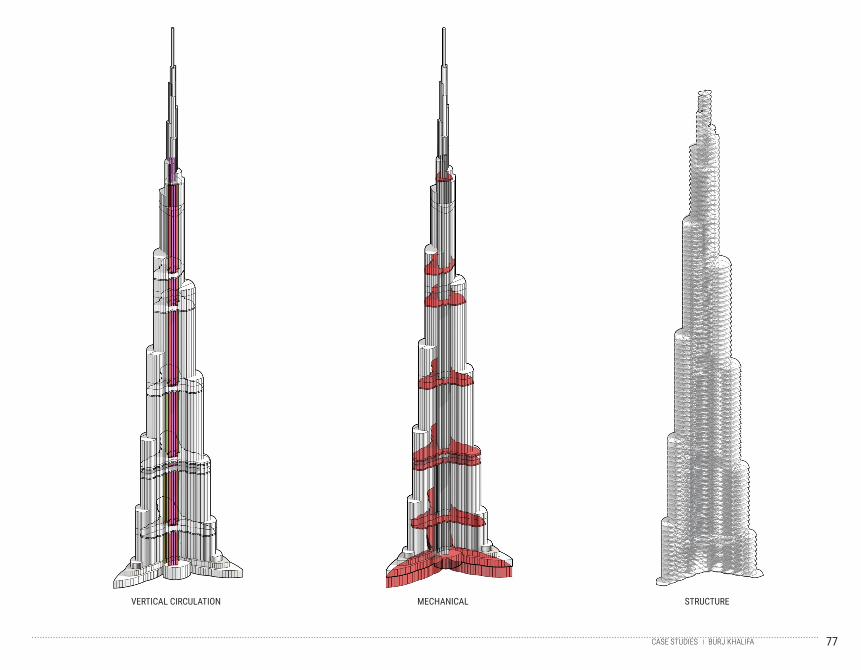
VERTICAL CIRCULATION MECHANICAL STRUCTURE
BURJ KHALIFACASE STUDIES
78
CA
SE
ST
UD
Y 1
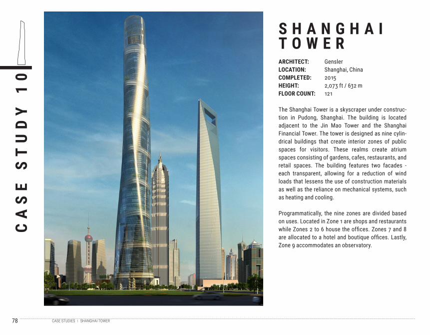
0S H A N G H A IT O W E RARCHITECT:LOCATION:COMPLETED:HEIGHT:FLOOR COUNT:
GenslerShanghai, China20152,073 ft / 632 m121
The Shanghai Tower is a skyscraper under construc-tion in Pudong, Shanghai. The building is located adjacent to the Jin Mao Tower and the Shanghai Financial Tower. The tower is designed as nine cylin-drical buildings that create interior zones of public spaces for visitors. These realms create atrium spaces consisting of gardens, cafes, restaurants, and retail spaces. The building features two facades - each transparent, allowing for a reduction of wind loads that lessens the use of construction materials as well as the reliance on mechanical systems, such as heating and cooling.
Programmatically, the nine zones are divided based on uses. Located in Zone 1 are shops and restaurants while Zones 2 to 6 house the offices. Zones 7 and 8 are allocated to a hotel and boutique offices. Lastly, Zone 9 accommodates an observatory.
SHANGHAI TOWERCASE STUDIES
79
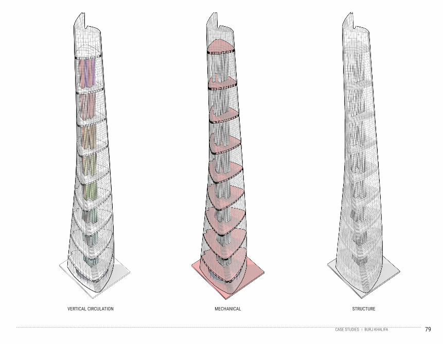
VERTICAL CIRCULATION MECHANICAL STRUCTURE
BURJ KHALIFACASE STUDIES
80
CA
SE
ST
UD
Y 1
1S H A N G H A IF I N A N C I A LT O W E RARCHITECT:LOCATION:COMPLETED:HEIGHT:FLOOR COUNT:
Kohn Pedersen FoxShanghai, China20081,621 ft / 494 m101
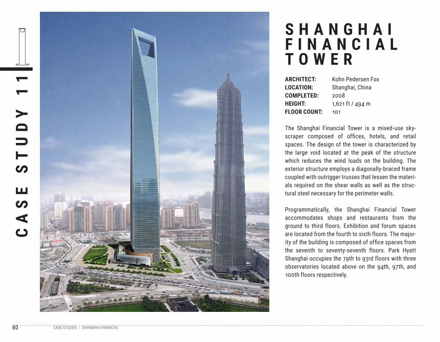
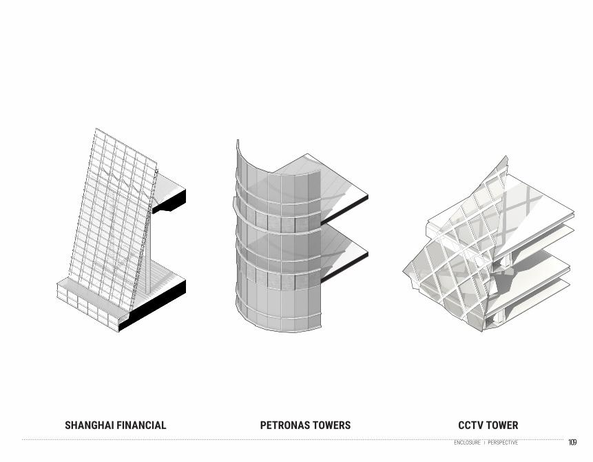
The Shanghai Financial Tower is a mixed-use sky-scraper composed of offices, hotels, and retail spaces. The design of the tower is characterized by the large void located at the peak of the structure which reduces the wind loads on the building. The exterior structure employs a diagonally-braced frame coupled with outrigger trusses that lessen the materi-als required on the shear walls as well as the struc-tural steel necessary for the perimeter walls.
Programmatically, the Shanghai Financial Tower accommodates shops and restaurants from the ground to third floors. Exhibition and forum spaces are located from the fourth to sixth floors. The major-ity of the building is composed of office spaces from the seventh to seventy-seventh floors. Park Hyatt Shanghai occupies the 79th to 93rd floors with three observatories located above on the 94th, 97th, and 100th floors respectively.
SHANGHAI FINANCIALCASE STUDIES
81
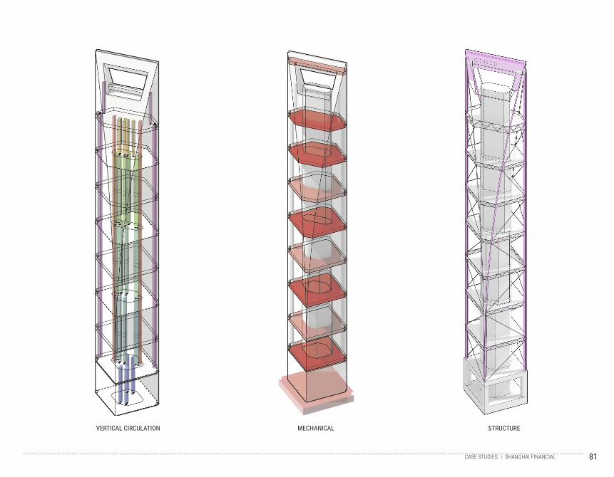
VERTICAL CIRCULATION MECHANICAL STRUCTURE
SHANGHAI FINANCIALCASE STUDIES
82
CA
SE
ST
UD
Y 1
2P E T R O N A ST O W E R SARCHITECT:LOCATION:COMPLETED:HEIGHT:FLOOR COUNT:
Cesar PelliKuala Lumpur, Malaysia19961,483 ft / 451 m88
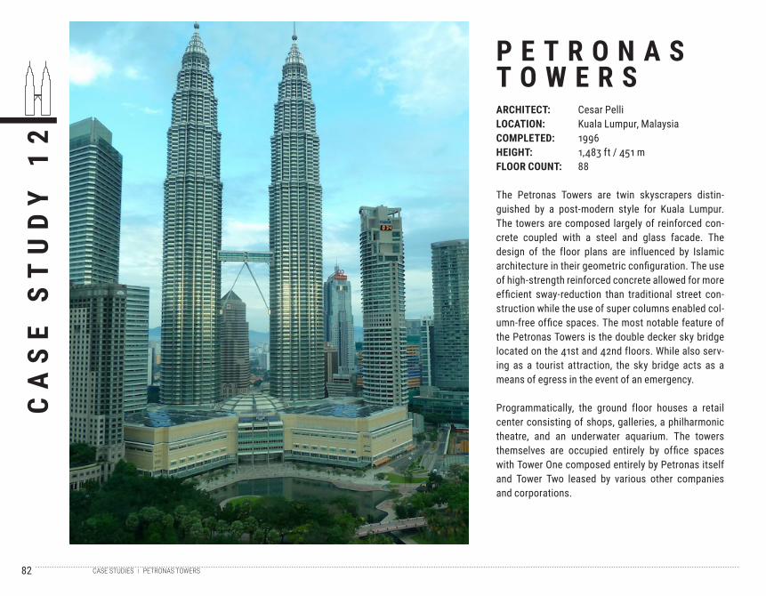
The Petronas Towers are twin skyscrapers distin-guished by a post-modern style for Kuala Lumpur. The towers are composed largely of reinforced con-crete coupled with a steel and glass facade. The design of the floor plans are influenced by Islamic architecture in their geometric configuration. The use of high-strength reinforced concrete allowed for more efficient sway-reduction than traditional street con-struction while the use of super columns enabled col-umn-free office spaces. The most notable feature of the Petronas Towers is the double decker sky bridge located on the 41st and 42nd floors. While also serv-ing as a tourist attraction, the sky bridge acts as a means of egress in the event of an emergency.
Programmatically, the ground floor houses a retail center consisting of shops, galleries, a philharmonic theatre, and an underwater aquarium. The towers themselves are occupied entirely by office spaces with Tower One composed entirely by Petronas itself and Tower Two leased by various other companies and corporations.
PETRONAS TOWERSCASE STUDIES
83
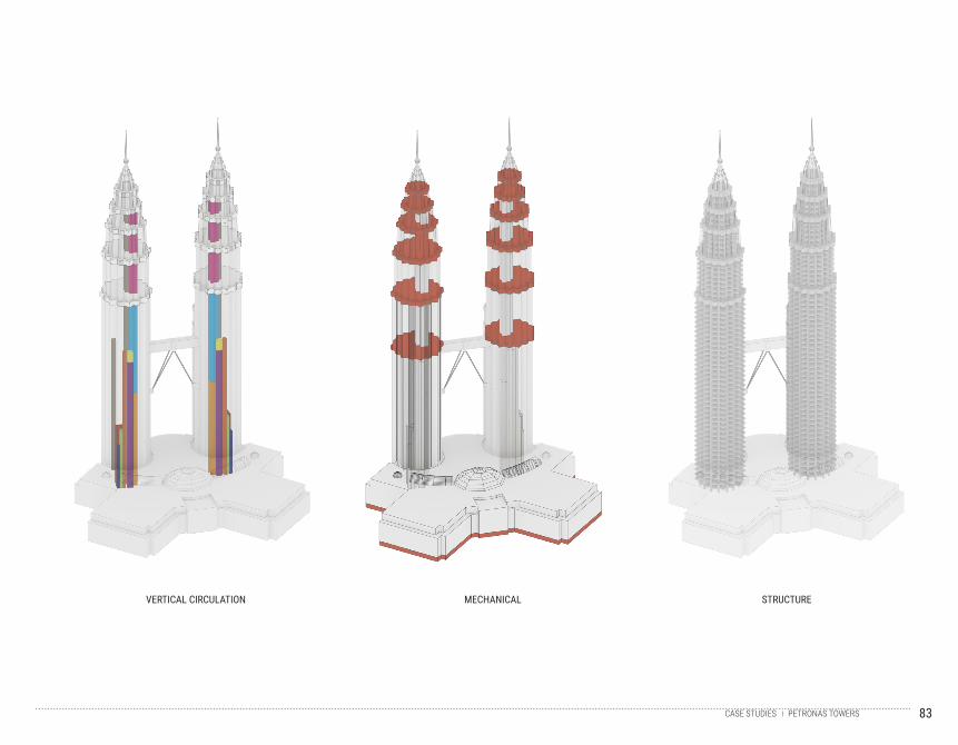
VERTICAL CIRCULATION MECHANICAL STRUCTURE
PETRONAS TOWERSCASE STUDIES
84
CA
SE
ST
UD
Y 1
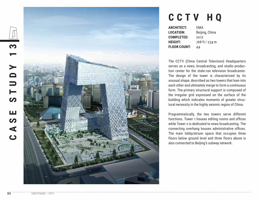
3C C T V H QARCHITECT:LOCATION:COMPLETED:HEIGHT:FLOOR COUNT:
OMABeijing, China2012768 ft / 234 m44
The CCTV (China Central Television) Headquarters serves as a news, broadcasting, and studio produc-tion center for the state-run television broadcaster. The design of the tower is characterized by its unusual shape, described as two towers that lean into each other and ultimately merge to form a continuous form. The primary structural support is composed of the irregular grid expressed on the surface of the building which indicates moments of greater struc-tural necessity in the highly seismic region of China.
Programmatically, the two towers serve different functions. Tower 1 houses editing rooms and offices while Tower 2 is dedicated to news broadcasting. The connecting overhang houses administrative offices. The main lobby/atrium space that occupies three floors below ground level and three floors above is also connected to Beijing’s subway network.
CCTVCASE STUDIES
85
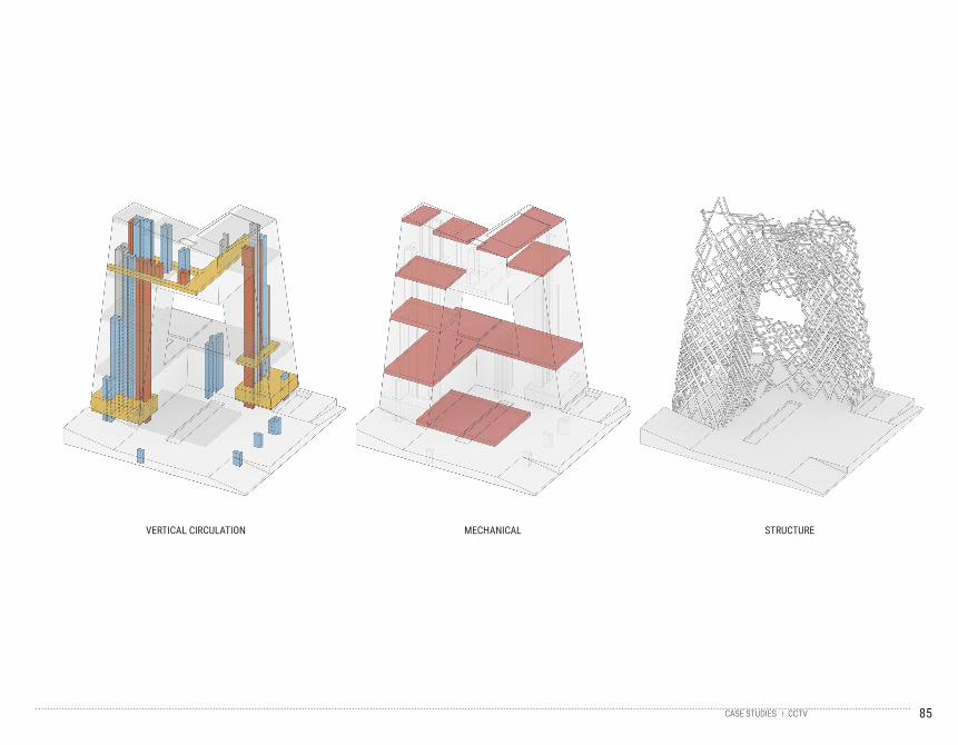
VERTICAL CIRCULATION MECHANICAL STRUCTURE
CCTVCASE STUDIES
86
87
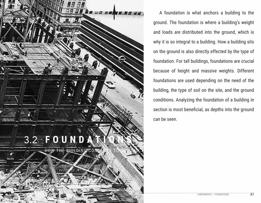
F O U N D A T I O N SHOW THE BUILDING CONNECTS TO GROUND
3.2
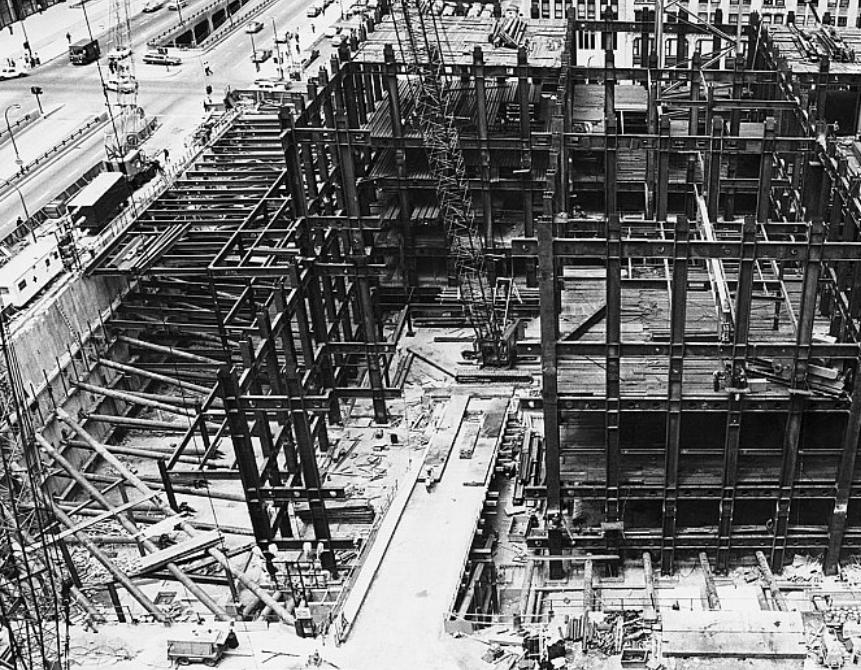
A foundation is what anchors a building to the
ground. The foundation is where a building’s weight
and loads are distributed into the ground, which is
why it is so integral to a building. How a building sits
on the ground is also directly effected by the type of
foundation. For tall buildings, foundations are crucial
because of height and massive weights. Different
foundations are used depending on the need of the
building, the type of soil on the site, and the ground
conditions. Analyzing the foundation of a building in
section is most beneficial, as depths into the ground
can be seen.
FOUNDATIONSCOMPONENTS
88
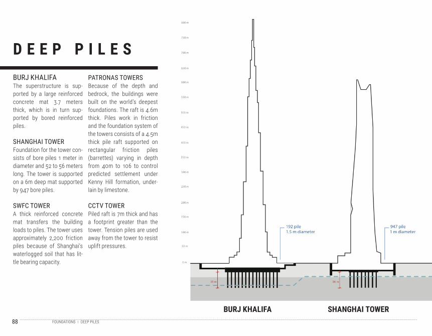
D E E P P I L E S
BURJ KHALIFA SHANGHAI TOWER
BURJ KHALIFAThe superstructure is sup-ported by a large reinforced concrete mat 3.7 meters thick, which is in turn sup-ported by bored reinforced piles.
SHANGHAI TOWERFoundation for the tower con-sists of bore piles 1 meter in diameter and 52 to 56 meters long. The tower is supported on a 6m deep mat supported by 947 bore piles.
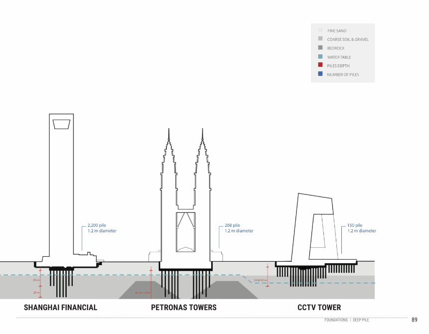
SWFC TOWERA thick reinforced concrete mat transfers the building loads to piles. The tower uses approximately 2,200 friction piles because of Shanghai’s waterlogged soil that has lit-tle bearing capacity.
PATRONAS TOWERSBecause of the depth and bedrock, the buildings were built on the world’s deepest foundations. The raft is 4.6m thick. Piles work in friction and the foundation system of the towers consists of a 4.5m thick pile raft supported on rectangular friction piles (barrettes) varying in depth from 40m to 106 to control predicted settlement under Kenny Hill formation, under-lain by limestone.
CCTV TOWERPiled raft is 7m thick and has a footprint greater than the tower. Tension piles are used away from the tower to resist uplift pressures.
DEEP PILESFOUNDATIONS
89
SHANGHAI FINANCIAL PETRONAS TOWERS CCTV TOWERDEEP PILEFOUNDATIONS
90
91
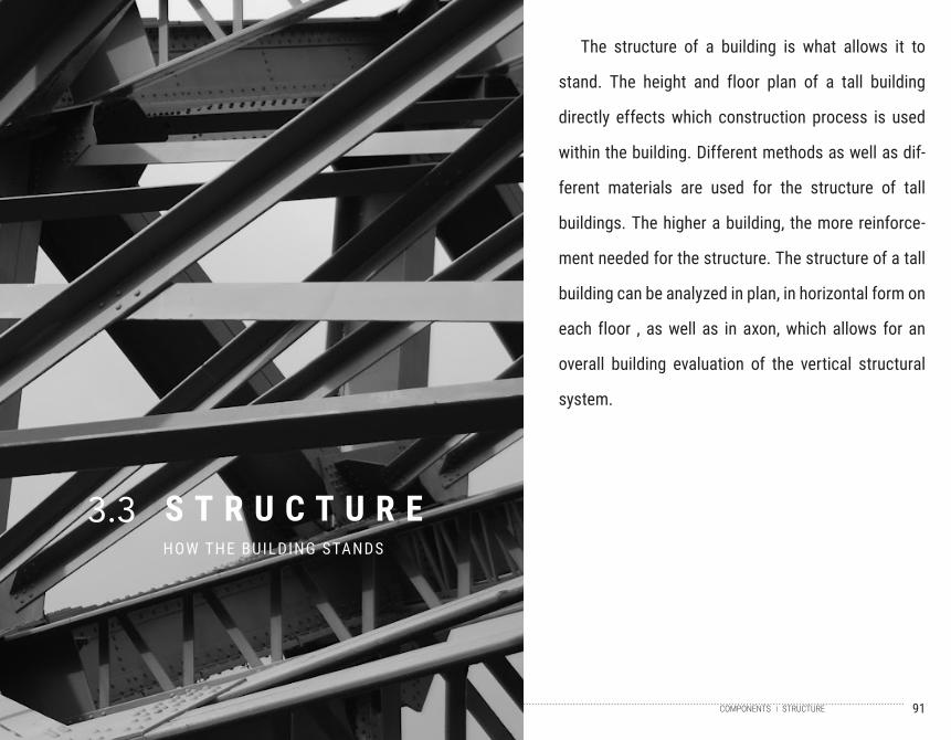
S T R U C T U R EHOW THE BUILDING STANDS
3.3
The structure of a building is what allows it to
stand. The height and floor plan of a tall building
directly effects which construction process is used
within the building. Different methods as well as dif-
ferent materials are used for the structure of tall
buildings. The higher a building, the more reinforce-
ment needed for the structure. The structure of a tall
building can be analyzed in plan, in horizontal form on
each floor , as well as in axon, which allows for an
overall building evaluation of the vertical structural
system.
STRUCTURECOMPONENTS
92
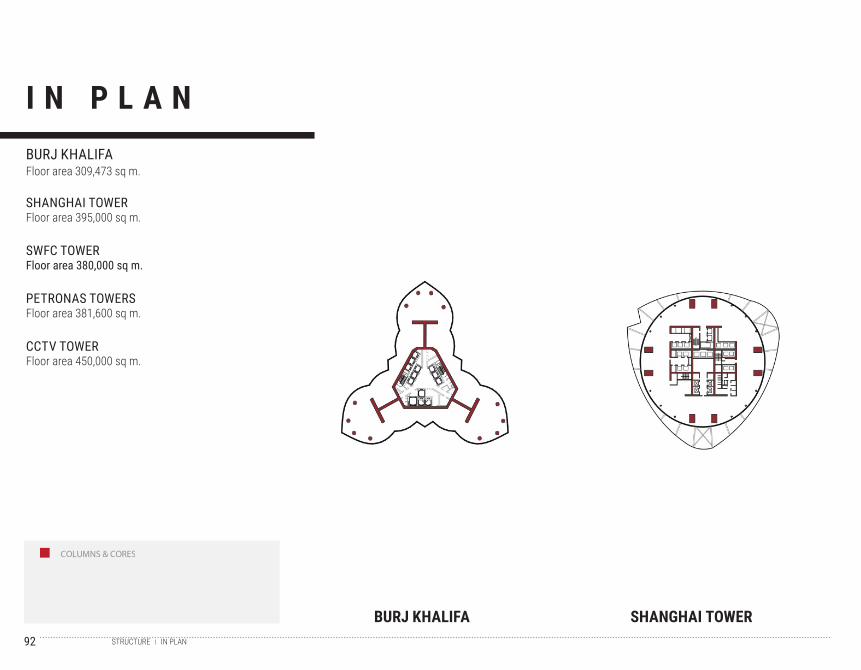
COLUMNS & CORES
I N P L A N
BURJ KHALIFA SHANGHAI TOWER
BURJ KHALIFAFloor area 309,473 sq m.
SHANGHAI TOWERFloor area 395,000 sq m.
SWFC TOWERFloor area 380,000 sq m.
PETRONAS TOWERSFloor area 381,600 sq m.
CCTV TOWERFloor area 450,000 sq m.
IN PLANSTRUCTURE
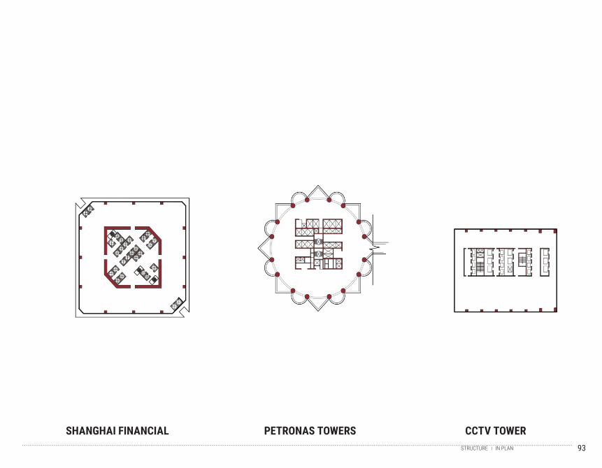
93
SHANGHAI FINANCIAL PETRONAS TOWERS CCTV TOWERIN PLANSTRUCTURE
94
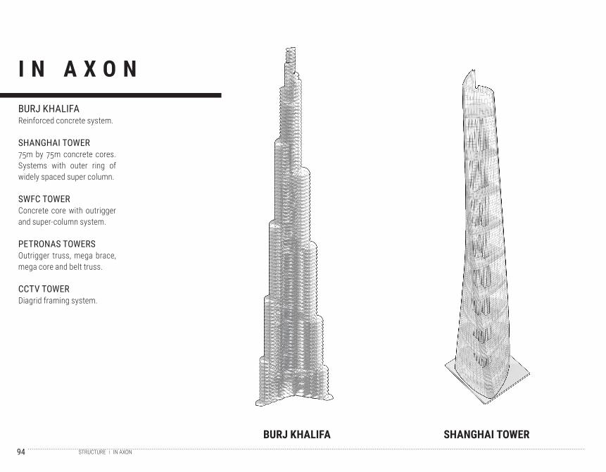
I N A X O N
BURJ KHALIFA SHANGHAI TOWER
BURJ KHALIFAReinforced concrete system.
SHANGHAI TOWER75m by 75m concrete cores. Systems with outer ring of widely spaced super column.
SWFC TOWERConcrete core with outrigger and super-column system.
PETRONAS TOWERSOutrigger truss, mega brace, mega core and belt truss.
CCTV TOWERDiagrid framing system.
IN AXONSTRUCTURE
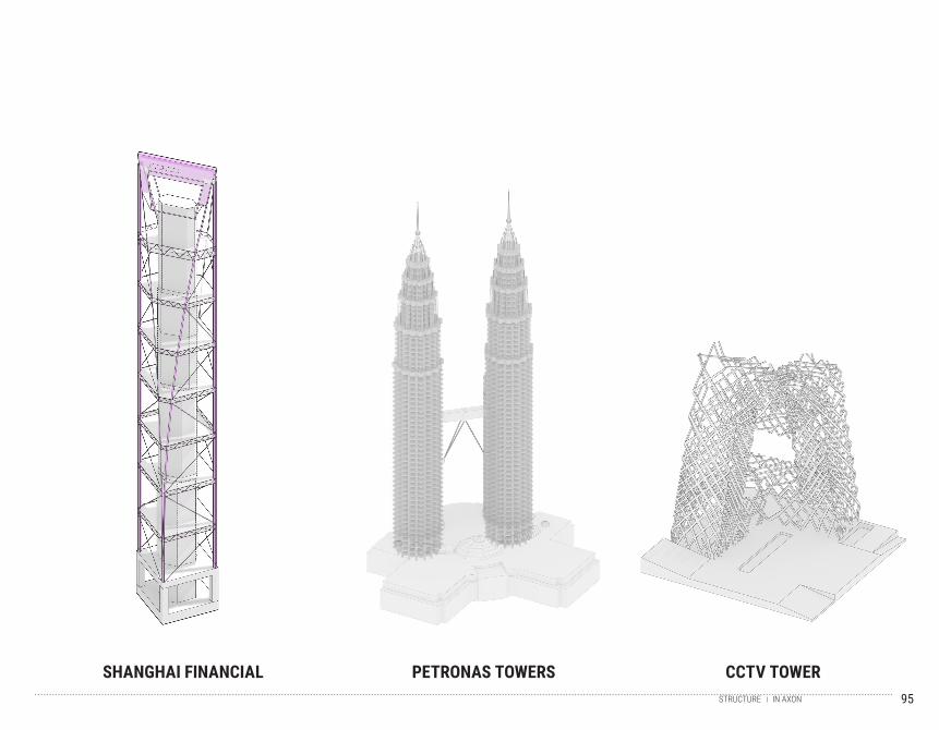
95
SHANGHAI FINANCIAL PETRONAS TOWERS CCTV TOWERIN AXONSTRUCTURE
96
97
V E R T I C A L S Y S T E M SHOW THE BUILDING FUNCTIONS
3.4
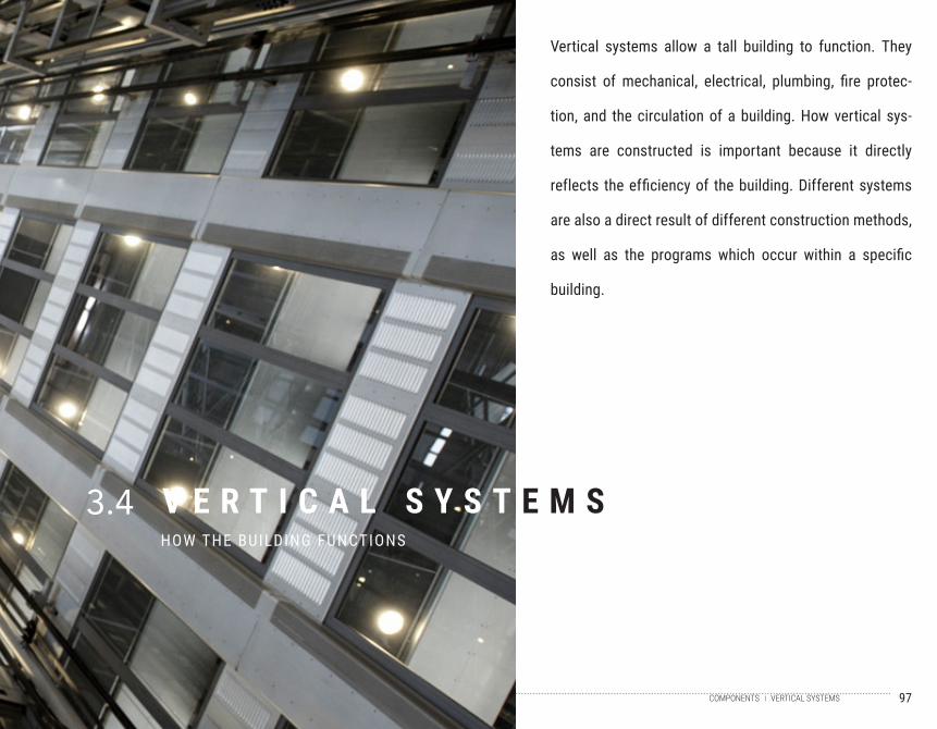
Vertical systems allow a tall building to function. They
consist of mechanical, electrical, plumbing, fire protec-
tion, and the circulation of a building. How vertical sys-
tems are constructed is important because it directly
reflects the efficiency of the building. Different systems
are also a direct result of different construction methods,
as well as the programs which occur within a specific
building.
VERTICAL SYSTEMSCOMPONENTS
98
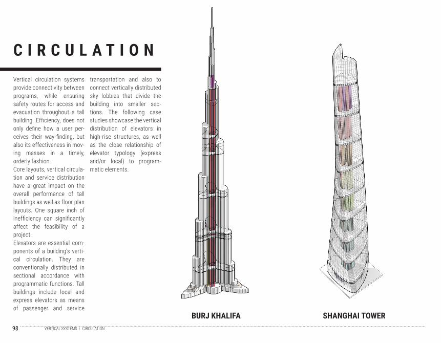
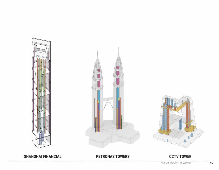
C I R C U L A T I O NVertical circulation systems provide connectivity between programs, while ensuring safety routes for access and evacuation throughout a tall building. Efficiency, does not only define how a user per-ceives their way-finding, but also its effectiveness in mov-ing masses in a timely, orderly fashion. Core layouts, vertical circula-tion and service distribution have a great impact on the overall performance of tall buildings as well as floor plan layouts. One square inch of inefficiency can significantly affect the feasibility of a project.Elevators are essential com-ponents of a building’s verti-cal circulation. They are conventionally distributed in sectional accordance with programmatic functions. Tall buildings include local and express elevators as means of passenger and service
transportation and also to connect vertically distributed sky lobbies that divide the building into smaller sec-tions. The following case studies showcase the vertical distribution of elevators in high-rise structures, as well as the close relationship of elevator typology (express and/or local) to program-matic elements.
BURJ KHALIFA SHANGHAI TOWERCIRCULATIONVERTICAL SYSTEMS
99
SHANGHAI FINANCIAL PETRONAS TOWERS CCTV TOWERCIRCULATIONVERTICAL SYSTEMS
100
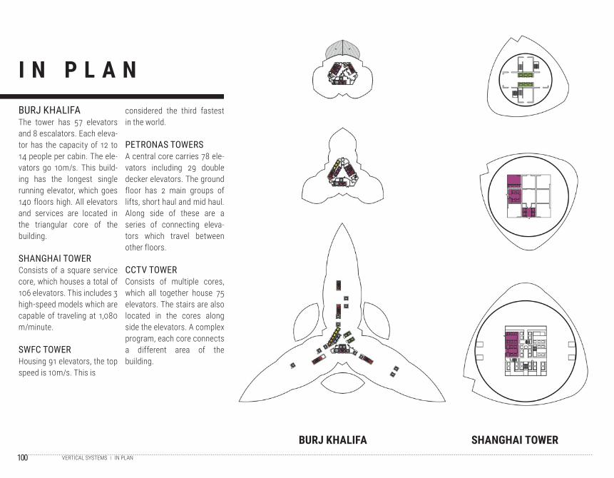
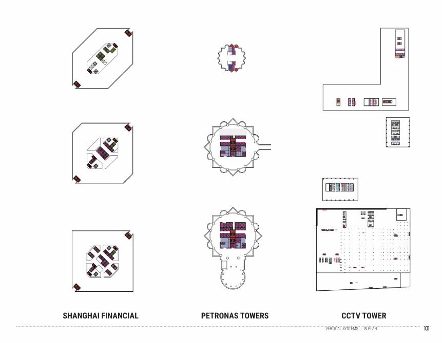
I N P L A N
BURJ KHALIFA SHANGHAI TOWER
BURJ KHALIFAThe tower has 57 elevators and 8 escalators. Each eleva-tor has the capacity of 12 to 14 people per cabin. The ele-vators go 10m/s. This build-ing has the longest single running elevator, which goes 140 floors high. All elevators and services are located in the triangular core of the building.
SHANGHAI TOWERConsists of a square service core, which houses a total of 106 elevators. This includes 3 high-speed models which are capable of traveling at 1,080 m/minute.
SWFC TOWERHousing 91 elevators, the top speed is 10m/s. This is
considered the third fastest in the world.
PETRONAS TOWERSA central core carries 78 ele-vators including 29 double decker elevators. The ground floor has 2 main groups of lifts, short haul and mid haul. Along side of these are a series of connecting eleva-tors which travel between other floors.
CCTV TOWERConsists of multiple cores, which all together house 75 elevators. The stairs are also located in the cores along side the elevators. A complex program, each core connects a different area of the building.
IN PLANVERTICAL SYSTEMS
101
SHANGHAI FINANCIAL PETRONAS TOWERS CCTV TOWERIN PLANVERTICAL SYSTEMS
102
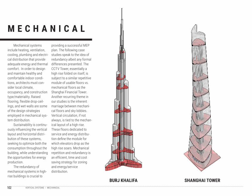
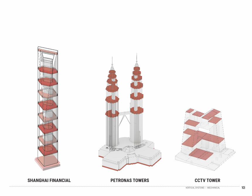
Mechanical systems include heating, ventilation, cooling, plumbing and electri-cal distribution that provide adequate energy and thermal comfort. In order to design and maintain healthy and comfortable indoor condi-tions, architects must con-sider local climate, occupancy, and construction type/materiality. Raised flooring, flexible drop-ceil-ings, and wet-walls are some of the design strategies employed in mechanical sys-tem distribution.
Sustainability is continu-ously influencing the vertical layout and horizontal distri-bution of these systems, seeking to optimize both the consumption throughout the building, while understanding the opportunities for energy production.
The redundancy of mechanical systems in high-rise buildings is crucial to
providing a successful MEP plan. The following case studies speak to the idea of redundancy albeit any formal differences presented. The CCTV Tower, essentially a high rise folded on itself, is subject to a similar repetitive module of usable floors vs. mechanical floors as the Shanghai Financial Tower. Another recurring theme in our studies is the inherent marriage between mechani-cal floors and sky lobbies. Vertical circulation, if not always, is tied to the mechan-ical layout of a high rise. These floors dedicated to service and energy distribu-tion define the module for which elevators drop as the high rise soars. Mechanical repetition and redundancy is an efficient, time and cost saving strategy for zoning and energy/service distribution.
M E C H A N I C A L
BURJ KHALIFA SHANGHAI TOWERMECHANICALVERTICAL SYSTEMS
103
SHANGHAI FINANCIAL PETRONAS TOWERS CCTV TOWERMECHANICALVERTICAL SYSTEMS
104
P R O G R A M
BURJ KHALIFA SHANGHAI TOWER
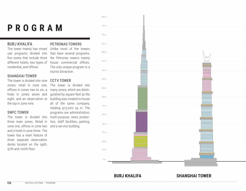
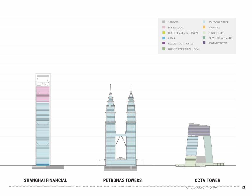
BURJ KHALIFAThe tower mainly has mixed use programs divided into five zones that include three different hotels, two types of residential, and offices.
SHANGHAI TOWERThe tower is divided into nine zones; retail in zone one, offices in zones two to six, a hotel in zones seven and eight, and an observation at the top in zone nine.
SWFC TOWERThe tower is divided into three main zones. Retail in zone one, offices in zone two and a hotel in zone three. The tower has a main feature of three separate observation decks located on the 94th, 97th and 100th floor.
PETRONAS TOWERSUnlike most of the towers that have several programs, the Petronas towers mainly house commercial offices. The only unique program is a tourist attraction.
CCTV TOWERThe tower is divided into many zones, which are distin-guished by square feet as the building was created to house all of the same company; totaling 473,000 sq m. The programs are administration, multi-purpose, news produc-tion, staff facilities, parking, and a service building.
PROGRAMVERTICAL SYSTEMS
105
SHANGHAI FINANCIAL PETRONAS TOWERS CCTV TOWERPROGRAMVERTICAL SYSTEMS
106
107
E N C L O S U R EFACADE AND SKIN
3.5
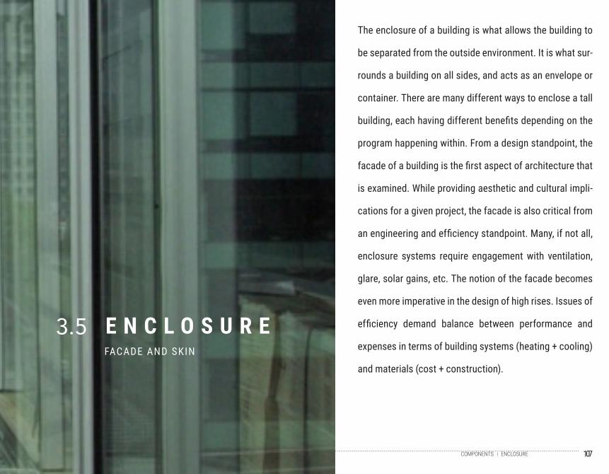
The enclosure of a building is what allows the building to
be separated from the outside environment. It is what sur-
rounds a building on all sides, and acts as an envelope or
container. There are many different ways to enclose a tall
building, each having different benefits depending on the
program happening within. From a design standpoint, the
facade of a building is the first aspect of architecture that
is examined. While providing aesthetic and cultural impli-
cations for a given project, the facade is also critical from
an engineering and efficiency standpoint. Many, if not all,
enclosure systems require engagement with ventilation,
glare, solar gains, etc. The notion of the facade becomes
even more imperative in the design of high rises. Issues of
efficiency demand balance between performance and
expenses in terms of building systems (heating + cooling)
and materials (cost + construction).
ENCLOSURECOMPONENTS

108
P E R S P E C T I V E
BURJ KHALIFA SHANGHAI TOWER
BURJ KHALIFACurtain Wall/ Aluminum + SteelThe Burj Khalifa features alu-minum and stainless steel spandrel panels with vertical fins. The facade consists of over 26,000 panels of glass, providing thermal comfort and anti-glare in the intense desert climate.
SHANGHAI TOWERDouble Skin/ SteelThe Shanghai Tower is char-acterized by the use of a transparent double-skin facade. The use of the dou-ble-skin not only reduces the wind loads on the building, but also allows for a reduction of structural steel required in the construction of the tower.
SWFC TOWERCurtain Wall/ SteelThe Shanghai Tower employs a glazed curtain wall system that reflects the surrounding environment. The facade is arranged within modules that
repeat every 13 floors, allow-ing for efficiency in both the use of materials and the cost of construction.
PETRONAS TOWERSCurtain Wall/ SteelThe Petronas Towers are identified by the diamond-fac-eted facade that consists of stainless steel extrusions that evoke motifs of Islamic architecture. Additionally, a panel curtain wall system of laminated glass reduces heat gains and glare.
CCTV TOWERDiagrid/SteelThe CCTV Headquarters is predominantly defined by the diagrid system visible on the external surface. The ‘exoskel-eton’ of the building features irregular (non-uniform) densi-ties in specific areas of the tower, creating unique compo-sitions on different facades.
IN AXONENCLOSURE
109
SHANGHAI FINANCIAL PETRONAS TOWERS CCTV TOWERPERSPECTIVEENCLOSURE

110
111
L O O K I N G F O R W A R D4
After the gathering of a complete and whole understanding of tall buildings, the research team
each took a focus in one direction, which will then become their thesis project in this studio. The
following section will introduce each student’s thesis project.
112
AM
AN
I
AMANILOOKING FORWARD
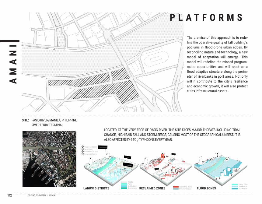
The premise of this approach is to rede-fine the operative quality of tall building’s podiums in flood-prone urban edges. By reconciling nature and technology, a new model of adaptation will emerge. This model will redefine the missed program-matic opportunities and will react as a flood adaptive structure along the perim-eter of riverbanks in port areas. Not only will it contribute to the city’s resilience and economic growth, it will also protect cities infrastructural assets.
P L A T F O R M S
SITE: PASIG RIVER/MANILA, PHILIPPINERIVER FERRY TERMINAL
LOCATED AT THE VERY EDGE OF PASIG RIVER, THE SITE FACES MAJOR THREATS INCLUDING TIDAL CHANGE , HIGH RAIN FALL AND STORM SERGE, CAUSING MOST OF THE GEOGRAPHICAL UNREST. IT IS ALSO AFFECTED BY 6 TO 7 TYPHOONS EVERY YEAR.
LANDS/ DISTRICTS RECLAIMED ZONES FLOOD ZONESPasig river3-6 Meter2-5 Meter
Reclaimed AreasPreserved Areas
ParksInstitutions
Roads
Businesses
Financial DistrictPasig RiverHistorical DistrictPreserved Ruins
2
3
4
1
2
43
1
Financial/ Industrial DISTRICT
Historical/ Institutional DISTRICT
Open Spaces Parks
113AMANILOOKING FORWARD
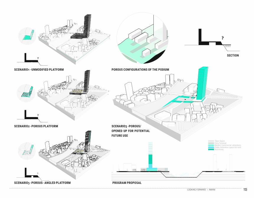
X
XX
SCENARIO3 -POROUS/ OPENED UP FOR POTENTIAL FUTURE USE
SCENARIO2 -POROUS PLATFORM
???
SCENARIO1 -UNMODIFIED PLATFORM
???
SCENARIO3 -POROUS- ANGLED PLATFORM
?
????
XXX
POROUS CONFIGURATIONS OF THE PODIUM
PROGRAM PROPOSAL
SECTION
Market/ Commercial attractionsFerry Terminal
Businesses
Open Space
Public Amenities (space for rent)
114
AR
ET
A
ARETALOOKING FORWARD
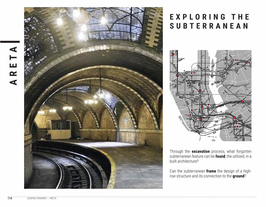
Through the excavation process, what forgotten subterranean feature can be found, the utilized, in a built architecture?
Can the subterranean frame the design of a high-rise structure and its connection to the ground?
E X P L O R I N G T H E S U B T E R R A N E A N
115ARETALOOKING FORWARD
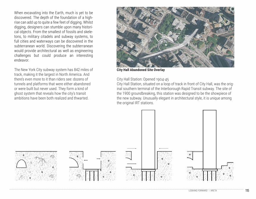
When excavating into the Earth, much is yet to be discovered. The depth of the foundation of a high-rise can add up to quite a few feet of digging. Whilst digging, designers can stumble upon many histori-cal objects. From the smallest of fossils and skele-tons, to military citadels and subway systems, to full cities and waterways can be discovered in the subterranean world. Discovering the subterranean would provide architectural as well as engineering challenges but could produce an interesting endeavor.
The New York City subway system has 842 miles of track, making it the largest in North America. And there’s even more to it than riders see: dozens of tunnels and platforms that were either abandoned or were built but never used. They form a kind of ghost system that reveals how the city’s transit ambitions have been both realized and thwarted.
City Hall Station: Opened 1904-45City Hall Station, situated on a loop of track in front of City Hall, was the orig-inal southern terminal of the Interborough Rapid Transit subway. The site of the 1900 groundbreaking, this station was designed to be the showpiece of the new subway. Unusually elegant in architectural style, it is unique among the original IRT stations.
City Hall Abandoned Site Overlay
116
CA
RO
LIN
A
CAROLINALOOKING FORWARD
The project seeks to understand how the informal occupation of the Tower of David and its unique circulation system fostered social interactions, while generating a sense of community. In con-trast to the social drawbacks of the conventional, isolating circulation system found in tall build-ings. Thus questioning the social benefits of the typical vertical circulation against the alternative, Skip-Stop circulation.
Among the advantages of the Skip-Stop proposed circulation system are as follows: speeding of vertical mobility, allowing for interim gathering spaces, encouraging those who can to use the stairs, thus providing health benefits for the users, while reducing the overall energy consump-tion.
T O W E R O F D A V I D :C A S E S T U D Y
“Torre de David, Informal Vertical Communities”, Brillembourg & Klumpner, (2013)
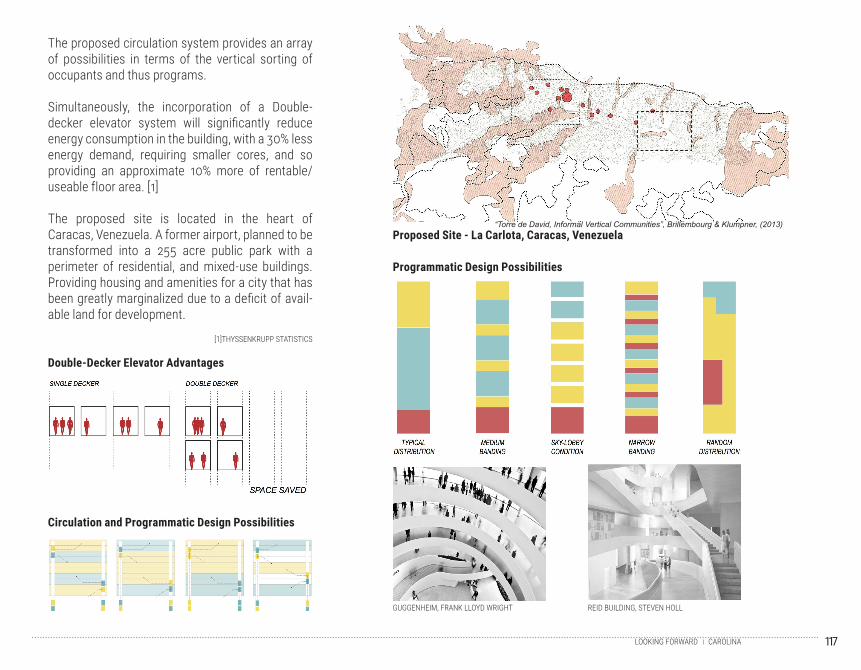
117CAROLINALOOKING FORWARD
The proposed circulation system provides an array of possibilities in terms of the vertical sorting of occupants and thus programs.
Simultaneously, the incorporation of a Double-decker elevator system will significantly reduce energy consumption in the building, with a 30% less energy demand, requiring smaller cores, and so providing an approximate 10% more of rentable/useable floor area. [1]
The proposed site is located in the heart of Caracas, Venezuela. A former airport, planned to be transformed into a 255 acre public park with a perimeter of residential, and mixed-use buildings. Providing housing and amenities for a city that has been greatly marginalized due to a deficit of avail-able land for development.
Proposed Site - La Carlota, Caracas, Venezuela
Circulation and Programmatic Design Possibilities
Double-Decker Elevator Advantages
Programmatic Design Possibilities
GUGGENHEIM, FRANK LLOYD WRIGHT
[1]THYSSENKRUPP STATISTICS
REID BUILDING, STEVEN HOLL
“Torre de David, Informal Vertical Communities”, Brillembourg & Klumpner, (2013)
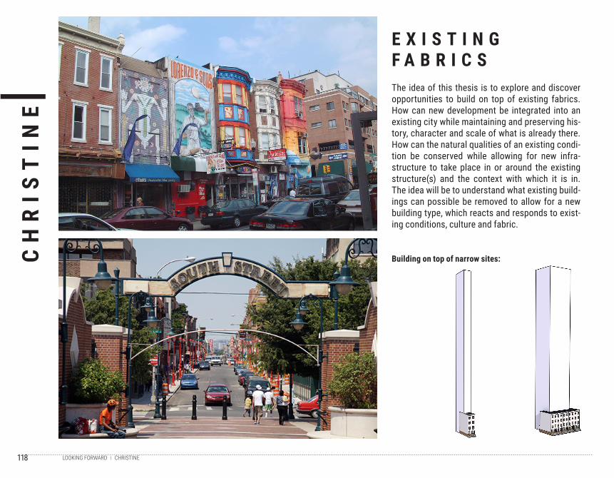
118
CH
RIS
TIN
E
CHRISTINELOOKING FORWARD
The idea of this thesis is to explore and discover opportunities to build on top of existing fabrics. How can new development be integrated into an existing city while maintaining and preserving his-tory, character and scale of what is already there. How can the natural qualities of an existing condi-tion be conserved while allowing for new infra-structure to take place in or around the existing structure(s) and the context with which it is in. The idea will be to understand what existing build-ings can possible be removed to allow for a new building type, which reacts and responds to exist-ing conditions, culture and fabric.
E X I S T I N G F A B R I C S
Building on top of narrow sites:
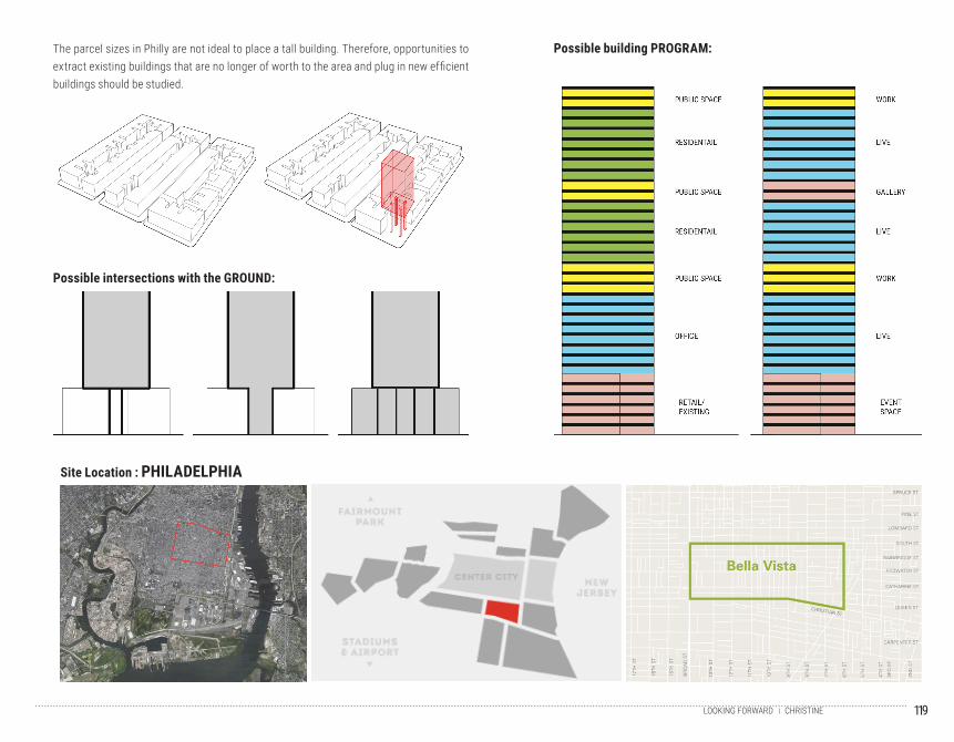
119CHRISTINELOOKING FORWARD
Site Location : PHILADELPHIA
Possible intersections with the GROUND:
Possible building PROGRAM:The parcel sizes in Philly are not ideal to place a tall building. Therefore, opportunities to extract existing buildings that are no longer of worth to the area and plug in new efficient buildings should be studied.
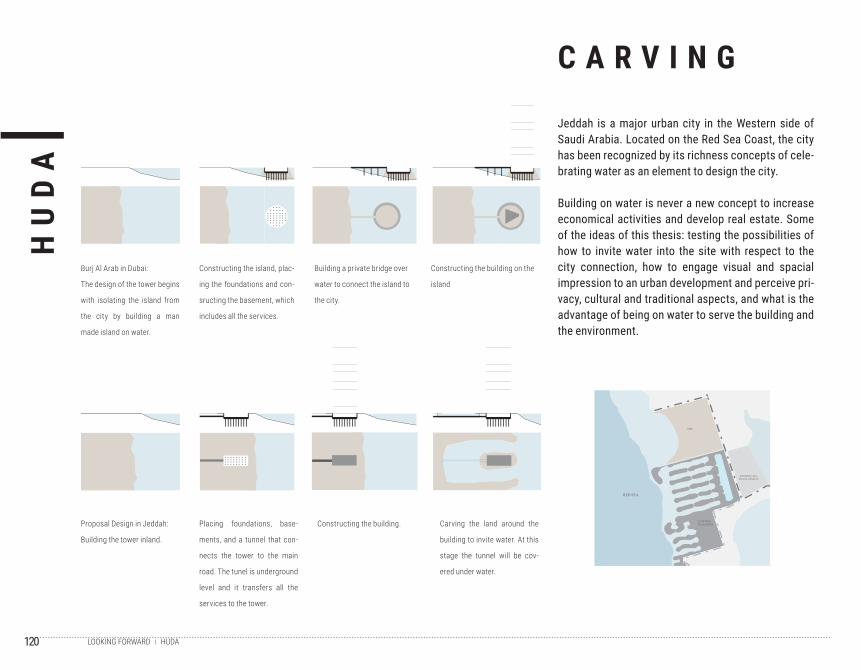
120
HU
DA
HUDALOOKING FORWARD
C A R V I N G
Jeddah is a major urban city in the Western side of Saudi Arabia. Located on the Red Sea Coast, the city has been recognized by its richness concepts of cele-brating water as an element to design the city.
Building on water is never a new concept to increase economical activities and develop real estate. Some of the ideas of this thesis: testing the possibilities of how to invite water into the site with respect to the city connection, how to engage visual and spacial impression to an urban development and perceive pri-vacy, cultural and traditional aspects, and what is the advantage of being on water to serve the building and the environment.
HU
DA
LA
MP
HO
N
CARVING
SITE: NORTH JEDDAH CITY BURJ D UBAI SITE CO NSTRUCTION VS. PROPOSAL SITE CONSTRUCTION
JEDDAH CITYIN CELEBRATION OF WATER
RED SEA
SITE
RESIDENTIAL DEVELOPMENT
EXISTING BUILDINGS
UNDE R A TER TUNNEL
� ��� A� A�� � �� D � � � ��T� � ����� � �� � �� � � � �� ���� � � � �� � ������ �� � �� � �� ���� � � � � � �� � ��� �� � � � ����� � �� � � �� �� ��� � �� �� �� �� � �
C� � � �� � � �� � � ��� � �� �� � � � �� ����� � � � ��� � ����� � � � ��� � �� ��� � � ����� � � � �� � ��� � �� ���� � ���� � ��� �� � ��� ��� �� �� ��
������ � � � � � �� ��� � � ���� � ����� ��� �� �� �� � ���� ��� ������ � � ��� � ����
C� � � �� � � ��� � ��� � ������� �� � ��� �� �� �
C� � � �� � � ��� � ��� � ������ �
JEDDAH I� A �AJO R �RBA N CITY IN WE�TER N �ID E OF �A�D I ARABIA LOCATED ON THE RED � EA COA�T � THE CITY HA� BEEN RECO�NI�E D BY IT� RICHNE� � CONCE�T � OF CELEBRATIN� WATER A� AN ELE�EN T TO DE�I� N THE CITY�
B�I LDIN� ON WATER I� NE� ER A NEW CONCE�T T O INCREA�E ECONO�ICA L ACTI�I TIE� AND DE�E LO� REAL �TATE� TE� TIN� THE � O��I BILITIE� OF HOW TO IN� ITE WATER INTO THE � ITE WITH RE� � ECT TO THE CITY CONNECTION� HOW TO EN�A�E � I��A L AND � �A �CIAL I��RE� �I ON TO AN �RBAN DE��ELO� �EN T AND � ERCEI�E �RI � ACY� C� LT�RA L� AND TRADITIONAL A���EC T� � HOW TO � ET AN AD�A NTA�E OF BEIN� ON WATER TO � ER�E THE B�I LDIN� AND THE EN�I RON�ENT �
RE�IDENTIA� DEVE�O��ENTE�I�TING ��I�DING� RE�ORTD�RRAT A��ARO���NDEVE�O�ED �AND�
�AIN ROAD�RIVATE ROAD�ITE
�� ���� � � �� � ����� � �� � ��� � � � � �� ��� � ��� � �� ���� �� � � � �� � � � �� � � � �� ��� ���� �� �� � T� � �� � � � � �� � � �� � � ���� �� � � ����� �� � � � ��� �� � �� � � ��� ��� � � � � ��� ���� �� � �� ���� �� �� � �� ��� � �E ��
�E R� ICE� �� �E �� � ODI� � OFFICE� HOTEL CONDO�INI �� �
�O NE � � �� BLIC �O NE � � �E�I �� �B LIC �O NE � � �R I�AT ETUNN EL PRO R AMS
CAR�� T�NNE L
�LA�� A��ARI��
�NDER�RO�ND �E�
RETAIL� CO��ERCIA L�AIN ROAD
�� �� �� � � D � ��� � �� J � ��� � ����� � ��� ��� � ���� �� � �� � �
C�� ��� � �� � ���� �� � ��� � � � � � � ����� � � ������ � � �� � � A� ��� � � ���� � � � �� � � �� � ��� � � �� ��� �� � ����� � � �� ��
Burj Al Arab in Dubai:
The design of the tower begins
with isolating the island from
the city by building a man
made island on water.
Constructing the island, plac-
ing the foundations and con-
sructing the basement, which
includes all the services.
Building a private bridge over
water to connect the island to
the city.
Constructing the building on the
island
Proposal Design in Jeddah:
Building the tower inland.
Placing foundations, base-
ments, and a tunnel that con-
nects the tower to the main
road. The tunel is underground
level and it transfers all the
services to the tower.
Constructing the building. Carving the land around the
building to invite water. At this
stage the tunnel will be cov-
ered under water.
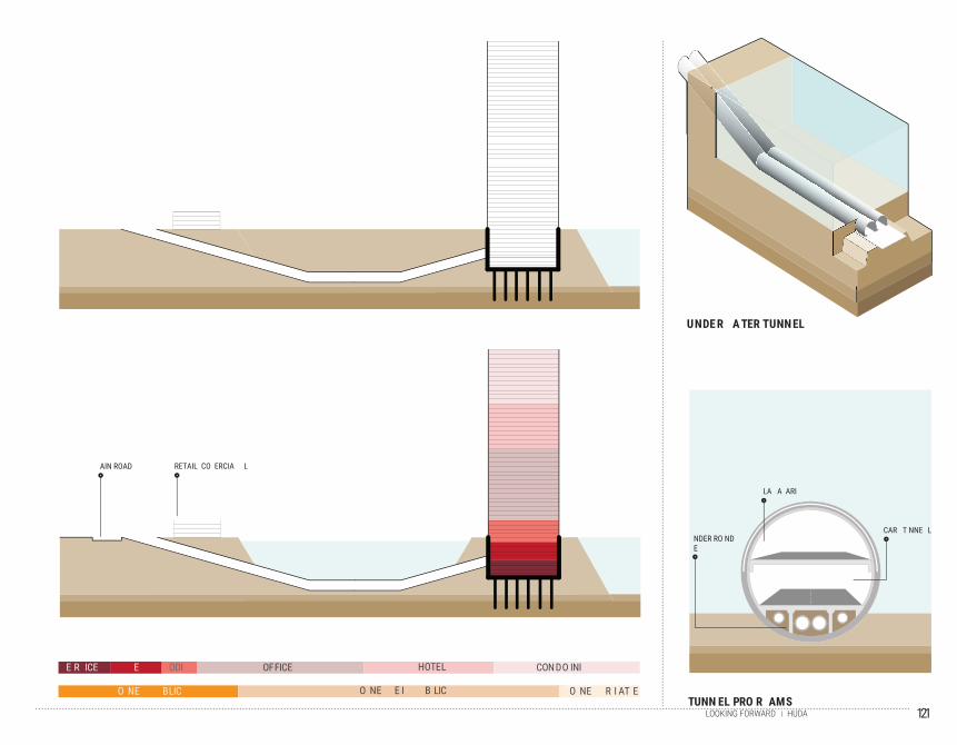
121HUDALOOKING FORWARD
HU
DA
LA
MP
HO
N
CARVING
SITE: NORTH JEDDAH CITY BURJ D UBAI SITE CO NSTRUCTION VS. PROPOSAL SITE CONSTRUCTION
JEDDAH CITYIN CELEBRATION OF WATER
RED SEA
SITE
RESIDENTIAL DEVELOPMENT
EXISTING BUILDINGS
UNDE R A TER TUNNEL
� ��� A� A�� � �� D � � � ��T� � ����� � �� � �� � � � �� ���� � � � �� � ������ �� � �� � �� ���� � � � � � �� � ��� �� � � � ����� � �� � � �� �� ��� � �� �� �� �� � �
C� � � �� � � �� � � ��� � �� �� � � � �� ����� � � � ��� � ����� � � � ��� � �� ��� � � ����� � � � �� � ��� � �� ���� � ���� � ��� �� � ��� ��� �� �� ��
������ � � � � � �� ��� � � ���� � ����� ��� �� �� �� � ���� ��� ������ � � ��� � ����
C� � � �� � � ��� � ��� � ������� �� � ��� �� �� �
C� � � �� � � ��� � ��� � ������ �
JEDDAH I� A �AJO R �RBA N CITY IN WE�TER N �ID E OF �A�D I ARABIA LOCATED ON THE RED � EA COA�T � THE CITY HA� BEEN RECO�NI�E D BY IT� RICHNE� � CONCE�T � OF CELEBRATIN� WATER A� AN ELE�EN T TO DE�I� N THE CITY�
B�I LDIN� ON WATER I� NE� ER A NEW CONCE�T T O INCREA�E ECONO�ICA L ACTI�I TIE� AND DE�E LO� REAL �TATE� TE� TIN� THE � O��I BILITIE� OF HOW TO IN� ITE WATER INTO THE � ITE WITH RE� � ECT TO THE CITY CONNECTION� HOW TO EN�A�E � I��A L AND � �A �CIAL I��RE� �I ON TO AN �RBAN DE��ELO� �EN T AND � ERCEI�E �RI � ACY� C� LT�RA L� AND TRADITIONAL A���EC T� � HOW TO � ET AN AD�A NTA�E OF BEIN� ON WATER TO � ER�E THE B�I LDIN� AND THE EN�I RON�ENT �
RE�IDENTIA� DEVE�O��ENTE�I�TING ��I�DING� RE�ORTD�RRAT A��ARO���NDEVE�O�ED �AND�
�AIN ROAD�RIVATE ROAD�ITE
�� ���� � � �� � ����� � �� � ��� � � � � �� ��� � ��� � �� ���� �� � � � �� � � � �� � � � �� ��� ���� �� �� � T� � �� � � � � �� � � �� � � ���� �� � � ����� �� � � � ��� �� � �� � � ��� ��� � � � � ��� ���� �� � �� ���� �� �� � �� ��� � �E ��
�E R� ICE� �� �E �� � ODI� � OFFICE� HOTEL CONDO�INI �� �
�O NE � � �� BLIC �O NE � � �E�I �� �B LIC �O NE � � �R I�AT ETUNN EL PRO R AMS
CAR�� T�NNE L
�LA�� A��ARI��
�NDER�RO�ND �E�
RETAIL� CO��ERCIA L�AIN ROAD
�� �� �� � � D � ��� � �� J � ��� � ����� � ��� ��� � ���� �� � �� � �
C�� ��� � �� � ���� �� � ��� � � � � � � ����� � � ������ � � �� � � A� ��� � � ���� � � � �� � � �� � ��� � � �� ��� �� � ����� � � �� ��
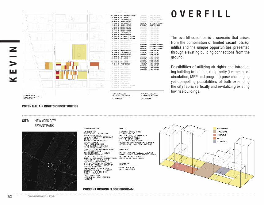
122
KE
VIN
KEVINLOOKING FORWARD
SITE: NEW YORK CITYBRYANT PARK
POTENTIAL AIR RIGHTS OPPORTUNITIES
O V E R F I L L
The overfill condition is a scenario that arises from the combination of limited vacant lots (or infills) and the unique opportunities presented through elevating building connections from the ground.
Possibilities of utilizing air rights and introduc-ing building-to-building reciprocity (i.e. means of circulation, MEP and program) pose challenging yet compelling possibilities of both expanding the city fabric vertically and revitalizing existing low rise buildings.
CURRENT GROUND FLOOR PROGRAM
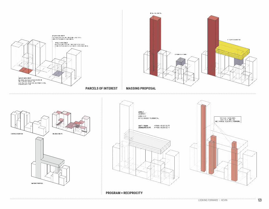
123KEVINLOOKING FORWARD
PROGRAM + RECIPROCITY
MASSING PROPOSALPARCELS OF INTEREST
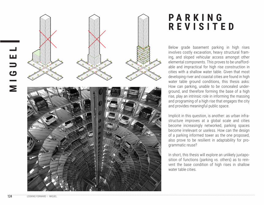
124
MIG
UE
L
MIGUELLOOKING FORWARD
Below grade basement parking in high rises involves costly excavation, heavy structural fram-ing, and sloped vehicular access amongst other elemental components. This proves to be unafford-able and impractical for high rise construction in cities with a shallow water table. Given that most developing river and coastal cities are found in high water table ground conditions, this thesis asks: How can parking, unable to be concealed under-ground, and therefore forming the base of a high rise, play an intrinsic role in informing the massing and programing of a high rise that engages the city and provides meaningful public space.
Implicit in this question, is another: as urban infra-structure improves at a global scale and cities become increasingly networked, parking spaces become irrelevant or useless. How can the design of a parking informed tower as the one proposed, also prove to be resilient in adaptability for pro-grammatic reuse?
In short, this thesis will explore an unlikely juxtapo-sition of functions (parking vs. others) as to rein-vent the base condition of high rises in shallow water table cities.
P A R K I N GR E V I S I T E D
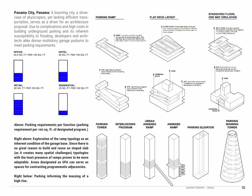
125MIGUELLOOKING FORWARD
Panama City, Panama: A booming city, a show-case of skyscrapers, yet lacking efficient trans-portation, serves as a driver for an architecture proposal. Due to complications and high costs in building underground parking and its inherent susceptibility to flooding, developers and archi-tects alike devise multistory garage podiums to meet parking requirements.
Above: Parking requirements per function (parking requirement per 100 sq. ft. of designated program.)
Right above: Exploration of the ramp typology as an inherent condition of the garage base. Since there is no great reason to build and reuse on sloped slab (as it creates many spatial challenges) typologies with the least presence of ramps proves to be more adaptable. Areas designated as UFA can serve as spaces for contrasting programmatic adjacencies.
Right below: Parking informing the massing of a high rise.
RESIDENTIAL:25 SQ. FT. PER 100 SQ. FT
RETAIL:80 SQ. FT. PER 100 SQ. FT.
. PER 100 SQ. FHOTEL:48 SQ. FT T
OFFICE:44.5 SQ. FT. PER 100 SQ. FT.
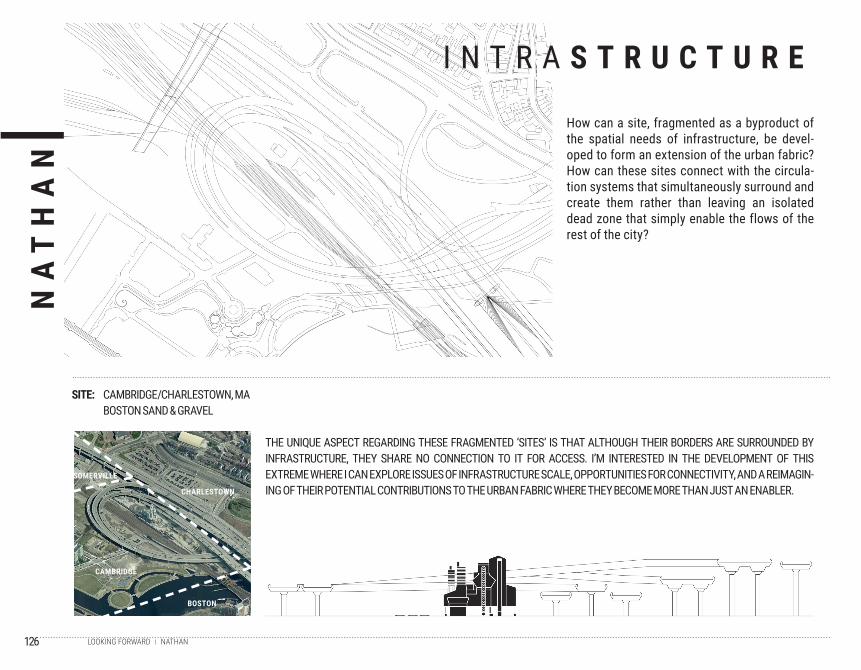
126
NA
TH
AN
NATHANLOOKING FORWARD
SITE: CAMBRIDGE/CHARLESTOWN, MABOSTON SAND & GRAVEL
BOSTON
CAMBRIDGE
SOMERVILLE
CHARLESTOWN
THE UNIQUE ASPECT REGARDING THESE FRAGMENTED ‘SITES’ IS THAT ALTHOUGH THEIR BORDERS ARE SURROUNDED BY INFRASTRUCTURE, THEY SHARE NO CONNECTION TO IT FOR ACCESS. I’M INTERESTED IN THE DEVELOPMENT OF THIS EXTREME WHERE I CAN EXPLORE ISSUES OF INFRASTRUCTURE SCALE, OPPORTUNITIES FOR CONNECTIVITY, AND A REIMAGIN-ING OF THEIR POTENTIAL CONTRIBUTIONS TO THE URBAN FABRIC WHERE THEY BECOME MORE THAN JUST AN ENABLER.
I N T R A S T R U C T U R E
How can a site, fragmented as a byproduct of the spatial needs of infrastructure, be devel-oped to form an extension of the urban fabric? How can these sites connect with the circula-tion systems that simultaneously surround and create them rather than leaving an isolated dead zone that simply enable the flows of the rest of the city?
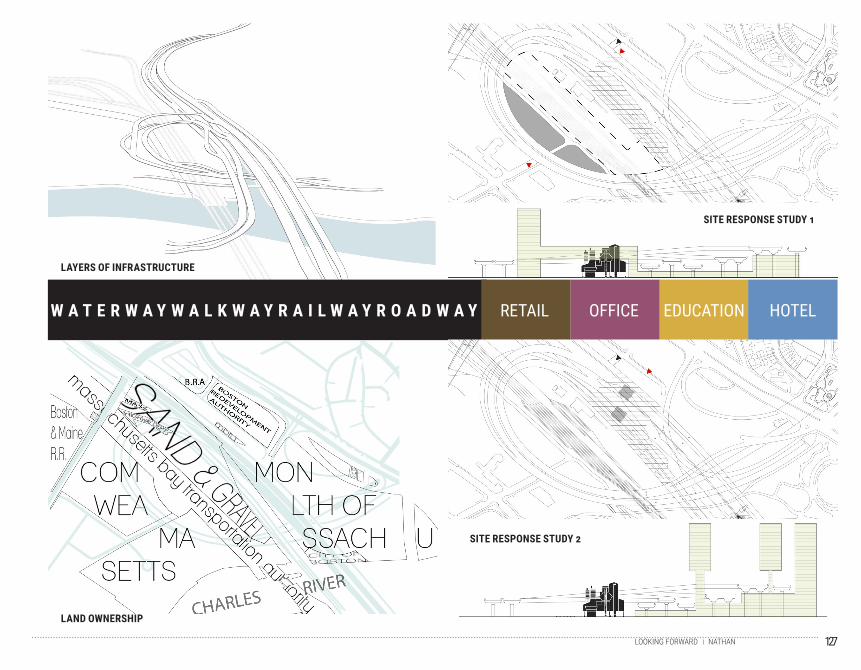
127NATHANLOOKING FORWARD
W A T E R W A Y W A L K W A Y R A I L W A Y R O A D W A Y RETAIL OFFICE EDUCATION HOTEL
SITE RESPONSE STUDY 1
SITE RESPONSE STUDY 2
LAYERS OF INFRASTRUCTURE
LAND OWNERSHIP
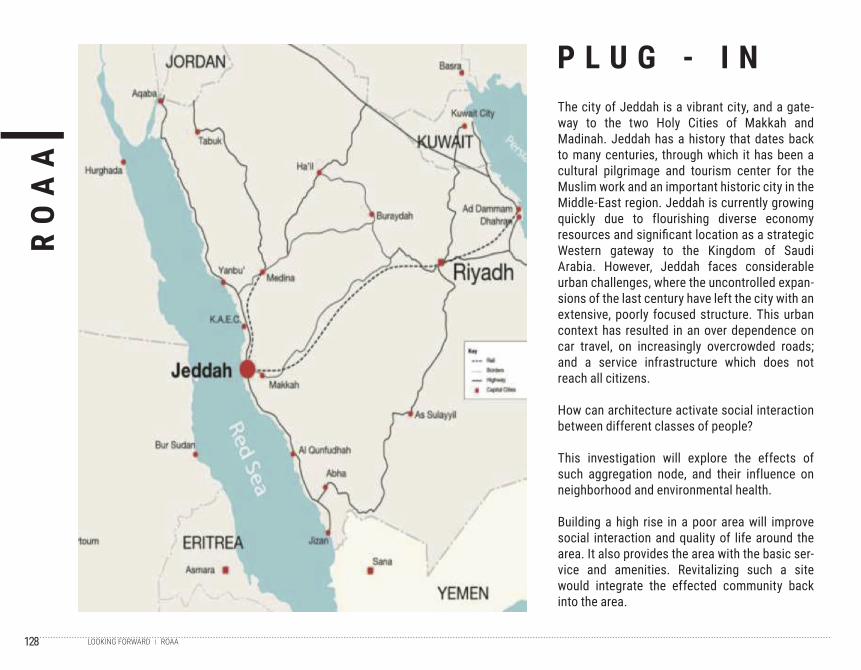
128
RO
AA
ROAALOOKING FORWARD
P L U G - I NThe city of Jeddah is a vibrant city, and a gate-way to the two Holy Cities of Makkah and Madinah. Jeddah has a history that dates back to many centuries, through which it has been a cultural pilgrimage and tourism center for the Muslim work and an important historic city in the Middle-East region. Jeddah is currently growing quickly due to flourishing diverse economy resources and significant location as a strategic Western gateway to the Kingdom of Saudi Arabia. However, Jeddah faces considerable urban challenges, where the uncontrolled expan-sions of the last century have left the city with an extensive, poorly focused structure. This urban context has resulted in an over dependence on car travel, on increasingly overcrowded roads; and a service infrastructure which does not reach all citizens.
How can architecture activate social interaction between different classes of people?
This investigation will explore the effects of such aggregation node, and their influence on neighborhood and environmental health.
Building a high rise in a poor area will improve social interaction and quality of life around the area. It also provides the area with the basic ser-vice and amenities. Revitalizing such a site would integrate the effected community back into the area.
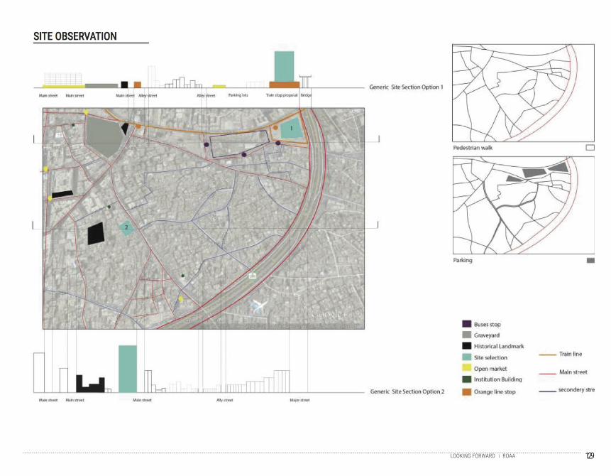
129ROAALOOKING FORWARD
130
Page 04 & 05
Introduction - New York Looking Up
h t t p : // i 2 . w p . c o m / j a v i e r a i s a . c o m / w p - c o n t e n t / u p l o a d s / 2 0 1 4 / 0 4 / D E S - 0 1 .
jpg?resize=500%2C333
Page 16 & 17
Image_Grand Central
http://www.adventuresofagoodman.com/wp-content/uploads/2012/02/Grand-Central-
Station-Met-Life-Building-Chrystler-Building.jpg
Page 20 & 21
Image_Hearst Tower Looking Up Diagonally
http://www.socalgreenrealestateblog.com/wp-content/uploads/2011/07/The-Hearst-Tower-
NYC.jpg
Hearst Floor Plan
http://www.arcspace.com/CropUp/-/media/31769/15hearst.jpg
Page 22 & 23
Image_Hearst Tower Section
http://esarq7.files.wordpress.com/2011/09/1124_fp247384_1.jpg
Page 24 & 25
Image_Vancouver Exchange Render
http://www.vancouversun.com/cms/binary/8788510.jpg
Image_Original Building Photograph
http://searcharchives.vancouver.ca/uploads/r/null/1/0/1034027/f5f67fa4-9ed2-4ee0-b841-
c6b6b7bf0367-A40180.jpg
Exchange Floorplan
http://www.archdaily.com/478111/harry-gugger-studio-s-the-exchange-to-rise-in-vancouver/
Page 26 & 27
Image_Vancouver Exchange Section
http://www.archdaily.com/478111/harry-gugger-studio-s-the-exchange-to-rise-in-vancouver/
32 & 33
Troll A View at Sea
http://www.offshoreenergytoday.com/wp-content/uploads/2014/06/Troll -A-gets-new-
compressors.jpg
Troll A View on Land with Platform
http://blog.piotrpietrzak.com/wp-content/uploads/2013/12/norway04.jpg
I M A G E C R E D I T S
Interior View of Troll A Leg
http://img.offshore.no/sak/Stats%20Group%20Troll%20A%20%20view%20from%20worksite.
jpg
38 & 39
Burj al-Arab Cover Shot
http://thehungrypartier.com/wp-content/uploads/2014/01/DSC02939.jpg
Burj al Arab Concrete Shore Close Up
http://3.bp.blogspot.com/-B7E-CJhPSiA/TzvCsGQP43I/AAAAAAAAAUA/ulXVUZ9bhgw/
s1600/5.jpg
Burj al Arab Island Bird’s Eye
http://rolandoruval.files.wordpress.com/2012/12/dubaitwo.jpg?w=300&h=210
44 & 45
onTerrain Image Topographical Layers
http://ad009cdnb.archdaily.net/wp-content/uploads/2011/03/1300909769-natural-topogra-
phy-without-buildings.jpg
Hoover Dam
http://www.usbr.gov/lc/phoenix/AZ100/1930/images/4a_Upstream-face-of-the-dam-near-
completion-Wash-No-3144.jpg
48 & 49
Holmenkollen View - Snow Covered Trees
http://jdsa.eu/wp-content/uploads/HOP-proj-18.jpg
Holmenkollen Ski Jump Site Plan
http://www.don-lawrence.com/assets/images/PROJECTS/holmenkollen/holmenkollen_ski_
jump_07.png
50 & 51
Holmenkollen - Section
http://www.architecturenewsplus.com/cdn/images/o/n/b/g/nbgbt81.jpg
52 & 53
High Cliff Tower - Mountain View
h t t p : / / w w w . s h a f i r . i n f o / s h a f i r _ i m a g e s / 1 0 A l b u m / 2 2 H o n g _
Kong~10Volume_3~100Morning~500The_Summit_and_Highcliff%5E1920x.jpg
131
56 & 57
Penn Station
http://upload.wikimedia.org/wikipedia/commons/thumb/f/f3/Acela_nearing_9th_Av_jeh.
jpg/1024px-Acela_nearing_9th_Av_jeh.jpg
60 & 61
Broadgate - Diagonal View of Plaza Side of Building
http://www.som.com/FILE/16124/broadgateexchangehouse_1400x800somlandalandelanc-
eywordsearchr_02jpg.jpg?h=800&s=17
Broadgate - Construction
http://www.mascontext.com/wp-content/uploads/2012/03/13_bridging_the_tracks_04.jpg
Broadgate - Site Plan (Bottom Right)
http://3.bp.blogspot.com/-VZgLPXKqpjo/TfntTpuNPuI/AAAAAAAACns/qy554MmAno4/
s1600/FIsXTvk.jpg
66 & 67
150 North Riverside Drive - Render
http://imagizer.imageshack.us/a/img809/5386/0nbo.jpg
150 North Riverside - Railroad Image
http://2.bp.blogspot.com/-hytvHMRTUkw/UearwywgJaI/AAAAAAAAUYo/3X20GD22wb0/
s1600/150_site.jpg
150 North Riverside - Plan (Bottom Left)
http://150northriverside.com/wp-content/uploads/150_Download_Sheets_v6.pdf
COMPONENTS
74 & 75
Components Case Studies Cover Photo
http://www.som.com/FILE/18929/willistower_structural_700x800_som_02_new2.jpg
76 & 77
Burj Khalifa
http://www.burjdubaiskyscraper.com/2010/02/burj0902.jpg
78 & 79
Shanghai Tower
http://www.dexigner.com/news/image/17776/Shanghai_Tower_01
80 & 81
Shanghai Financial Tower
h t t p : / / s 5 . p h o t o b u c k e t . c o m / u s e r / c i t y z / m e d i a / U r b a n /
ShanghaiWorldFinancialCenter5medium.jpg.html
82 & 83
Petronas Towers
http://www.48houradventure.com/wp-content/uploads/2013/02/Petronas-Towers.jpg
84 & 85
CCTV HQ
http://smg.photobucket.com/user/cityq/media/Urban/CCTVHeadquarters3smallA.jpg.html
86 & 87
Foundations Cover Photo
http://www.som.com/FILE/18930/willistower_structural_1400x800_som_01_new2.
jpg?h=800&s=17
90 & 91
Structure Cover Photo
http://1.bp.blogspot.com/-xULBOFX0w3w/UGXJQxJtIqI/AAAAAAAACUw/xmDf2hxoKxk/
s1600/DSC_0099.JPG
96 & 97
Vertical Systems Cover Photo
http://thelongroadtovenice.files.wordpress.com/2012/05/20120508_8743.jpg
106 & 107
Enclosure Cover Photo
http://www.tapchikientruc.com.vn/images/stories/chuyenmuc/kientrucnoithat/2011/06/
hinh%203-4_resize.jpg
THE DYNAMIC HIGHRISE
ARCH 7130 GRADUATE RESEARCH STUDIO
FALL 2014
This book summarizes the research semester
of a two semester course on High Rise design
at the Graduate School of Architecture at
Northeastern University. This course, the
third consecutive year of high-rise research,
is a two-semester research and design course
focused on the way tall structures meet the
ground. Given how many of these structures
are in the planning, design, and construction
stages around the world and how much of an
impact these large structures can have on the
urban experience, the grounding strategies
of high-rise buildings is an indispensable
body of research in need of greater attention
from the design community. This book is an
attempt to begin that effort.