Embed Size (px)
Citation preview
86
Lecture Note – 17
PRESTRESS CONCRETE Code: IS1343: 1980
Introduction: Definition of Prestress: Prestress is defined as a method of applying pre-compression to control the stresses resulting due to external loads below the neutral axis of the beam tension developed due to external load which is more than the permissible limits of the plain concrete. The pre-compression applied (may be axial or eccentric) will induce the compressive stress below the neutral axis or as a whole of the beam c/s. Resulting either no tension or compression. Basic Concept Prestressed concrete is basically concrete in which internal stresses of a suitable magnitude and distribution are introduced so that the stresses resulting from the external loads are counteracted to a desired degree. Terminology 1. Tendon: A stretched element used in a concrete member of structure to impart prestress to the concrete. 2. Anchorage: A device generally used to enable the tendon to impart and maintain prestress in concrete. 3. Pretensioning: A method of prestressing concrete in which the tendons are tensioned before the concrete is placed. In this method, the concrete is introduced by bond between steel & concrete. 4. Post-tensioning: A method of prestressing concrete by tensioning the tendons against hardened concrete. In this method, the prestress is imparted to concrete by bearing. Materials for prestress concrete members:
1. Cement: The cement used should be any of the following (a) Ordinary Portland cement conforming to IS269 (b) Portland slag cement conforming to IS455. But the slag content should not
be more than 50%. (c) Rapid hardening Portland cement conforming to IS8041. (d) High strength ordinary Portland cement conforming to IS8112.

87
2. Concrete: Prestress concrete requires concrete, which has a high compressive
strength reasonably early age with comparatively higher tensile strength than ordinary concrete. The concrete for the members shall be air-entrained concrete composed of Portland cement, fine and coarse aggregates, admixtures and water. The air-entraining feature may be obtained by the use of either air-entraining Portland cement or an approved air-entraining admixture. The entrained air content shall be not less than 4 percent or more than 6 percent.
Minimum cement content of 300 to 360 kg/m3 is prescribed for the durability requirement.
The water content should be as low as possible.
3. Steel:- High tensile steel , tendons , strands or cables The steel used in prestress shall be any one of the following:-
(a) Plain hard-drawn steel wire conforming to IS1785 (Part-I & Part-III) (b) Cold drawn indented wire conforming to IS6003 (c) High tensile steel wire bar conforming to IS2090 (d) Uncoated stress relived strand conforming to IS6006
High strength steel contains: 0.7 to 0.8% carbons, 0.6% manganese, 0.1% silica
Durability, Fire Resistance & Cover Requirements For P.S.C Members:- According to IS: 1343-1980 20 mm cover for pretensioned members 30 mm or size of the cable which ever is bigger for post tensioned members. If the prestress members are exposed to an aggressive environment, these covers are increased by another 10 mm. Necessity of high grade of concrete & steel: Higher the grade of concrete higher the bond strength which is vital in pretensioned concrete, Also higher bearing strength which is vital in post-tensioned concrete. Further creep & shrinkage losses are minimum with high-grade concrete.
Generally minimum M30 grade concrete is used for post-tensioned & M40 grade concrete is used for pretensioned members.
88
The losses in prestress members due to various reasons are generally in the range of 250 N/mm2 to 400 N/mm2. If mild steel or deformed steel is used the residual stresses after losses is either zero or negligible. Hence high tensile steel wires are used which varies from 1600 to 2000 N/mm2. Advantage of Prestressed Concrete
1. The use of high strength concrete and steel in prestressed members results in lighter and slender members than is possible with RC members.
2. In fully prestressed members the member is free from tensile stresses under working loads, thus whole of the section is effective.
3. In prestressed members, dead loads may be counter-balanced by eccentric prestressing.
4. Prestressed concrete member posses better resistance to shear forces due to effect of compressive stresses presence or eccentric cable profile.
5. Use of high strength concrete and freedom from cracks, contribute to improve durability under aggressive environmental conditions.
6. Long span structures are possible so that saving in weight is significant & thus it will be economic.
7. Factory products are possible. 8. Prestressed members are tested before use. 9. Prestressed concrete structure deflects appreciably before ultimate failure, thus
giving ample warning before collapse. 10. Fatigue strength is better due to small variations in prestressing steel,
recommended to dynamically loaded structures. Disadvantages of Prestressed Concrete
1. The availability of experienced builders is scanty. 2. Initial equipment cost is very high. 3. Availability of experienced engineers is scanty. 4. Prestressed sections are brittle 5. Prestressed concrete sections are less fire resistant.
Classifications and Types Prestressed concrete structures can be classified in a number of ways depending upon the feature of designs and constructions. 1. Pre-tensioning: In which the tendons are tensioned before the concrete is placed, tendons are temporarily anchored and tensioned and the prestress is transferred to the concrete after it is hardened.

89
2. Post-tensioning: In which the tendon is tensioned after concrete has hardened. Tendons are placed in sheathing at suitable places in the member before casting and later after hardening of concrete. The various methods by which pre-compression are imparted to concrete are classified as follows:
1. Generation of compressive force between the structural elements and its abutments using flat jack.
2. Development of hoop compression in cylindrically shaped structures by circumferential wire binding.
3. Use of longitudinally tensioned steel embedded in concrete or housed in ducts. 4. Use of principle of distortion of a statically indeterminate structure either by
displacement or by rotation of one part relative to the remainder. 5. Use of deflected structural steel sections embedded in concrete until the hardening
of the latter. 6. Development of limited tension in steel and compression in concrete by using
expanding cements. The most widely used method for prestressing of structural concrete elements is longitudinal tensioning of steel by different tensioning devices. Prestressing by the application of direct forces between abutments is generally used for arches and pavements, while flat jacks are invariably used to impart the desired forces. Tensioning Devices The various types devices used for tensioning steel are grouped under four principal categories, viz.
1. Mechanical devices: The mechanical devices generally used include weights with or without lever transmission, geared transmission in conjunction with pulley blocks, screw jacks with or without gear devices and wire-winding machines. These devices are employed mainly for prestressing structural concrete components produced on a mass scale in factory.
2. Hydraulic devices: These are simplest means for producing large prestressing force, extensively used as tensioning devices.
3. Electrical devices: The wires are electrically heated and anchored before placing concrete in the mould. This method is often referred to as thermo-prestressing and used for tensioning of steel wires and deformed bars.
4. Chemical devices: Expanding cements are used and the degree of expansion is controlled by varying the curing condition. Since the expansive action of cement
90
while setting is restrained, it induces tensile forces in tendons and compressive stresses in concrete.
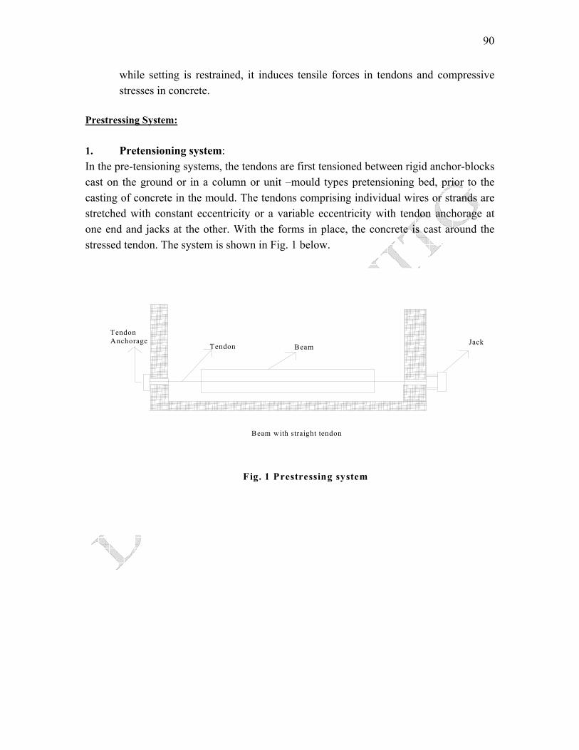
Prestressing System: 1. Pretensioning system: In the pre-tensioning systems, the tendons are first tensioned between rigid anchor-blocks cast on the ground or in a column or unit –mould types pretensioning bed, prior to the casting of concrete in the mould. The tendons comprising individual wires or strands are stretched with constant eccentricity or a variable eccentricity with tendon anchorage at one end and jacks at the other. With the forms in place, the concrete is cast around the stressed tendon. The system is shown in Fig. 1 below.
Tendon Anchorage
Tendon BeamJack
Fig. 1 Prestressing system
Beam with straight tendon
91
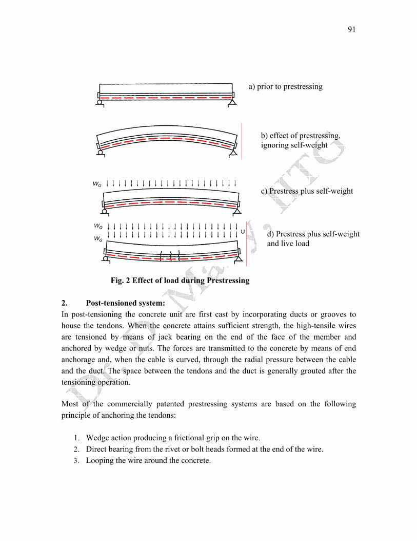
a) prior to prestressing
b) effect of prestressing, ignoring self-weight
c) Prestress plus self-weight
d) Prestress plus self-weight and live load
Fig. 2 Effect of load during Prestressing 2. Post-tensioned system: In post-tensioning the concrete unit are first cast by incorporating ducts or grooves to house the tendons. When the concrete attains sufficient strength, the high-tensile wires are tensioned by means of jack bearing on the end of the face of the member and anchored by wedge or nuts. The forces are transmitted to the concrete by means of end anchorage and, when the cable is curved, through the radial pressure between the cable and the duct. The space between the tendons and the duct is generally grouted after the tensioning operation.
Most of the commercially patented prestressing systems are based on the following principle of anchoring the tendons:
1. Wedge action producing a frictional grip on the wire. 2. Direct bearing from the rivet or bolt heads formed at the end of the wire. 3. Looping the wire around the concrete.
92
Methods:
1. Freyssinet system 2. Gifford-Udall system 3. Magnel blaton system 4. Lee-McCall system
Differnces of Prestressed Concrte Over Reinforced Concrete: 1. In prestress concrete member steel plays active role. The stress in steel prevails whether
external load is there or not. But in R.C.C., steel plays a passive role. The stress in steel in R.C.C members depends upon the external loads. i.e., no external load, no stress in steel.
2. In prestress concrete the stresses in steel is almost constant where as in R.C.C the stress in steel is variable with the lever arm.
3. Prestress concrete has more shear resistance, where as shear resistance of R.C.C is less. 4. In prestress concrete members, deflections are less because the eccentric prestressing
force will induce couple which will cause upward deflections, where as in R.C.C., deflections are more.
5. In prestress concrete fatigue resistance is more compare to R.C.C. because in R.C.C. stress in steel is external load dependent where as in P.S.C member it is load independent.
6. Prestress concrete is more durable as high grade of concrete is used which are more dense in nature. R.C.C. is less durable.
7. In prestress concrete dimensions are less because external stresses are counterbalance by the internal stress induced by prestress. Therefore reactions on column & footing are less as a whole the quantity of concrete is reduced by 30% and steel reduced by about 60 to 70%. R.C.C. is uneconomical for long span because in R.C.C. dimension of sections are large requiring more concrete & steel. Moreover as self-weight increases more reactions acted on columns & footings, which requires higher sizes.
93
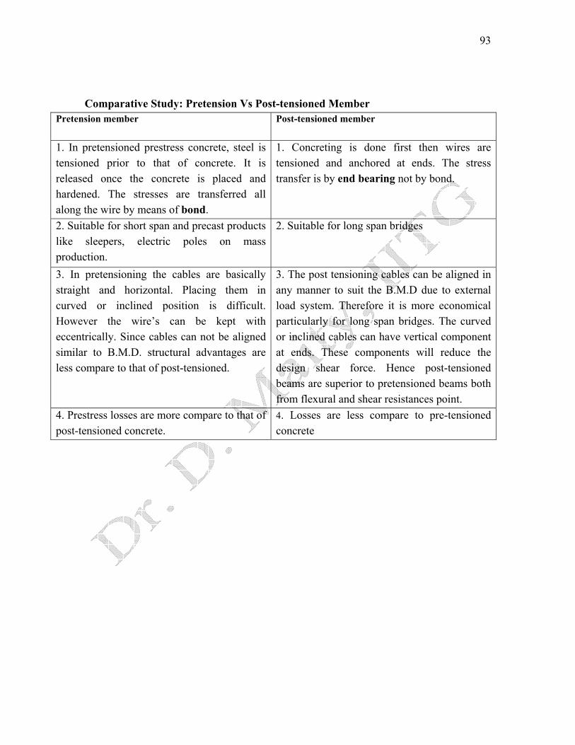
Comparative Study: Pretension Vs Post-tensioned Member Pretension member Post-tensioned member
1. In pretensioned prestress concrete, steel is tensioned prior to that of concrete. It is released once the concrete is placed and hardened. The stresses are transferred all along the wire by means of bond.
1. Concreting is done first then wires are tensioned and anchored at ends. The stress transfer is by end bearing not by bond.
2. Suitable for short span and precast products like sleepers, electric poles on mass production.
2. Suitable for long span bridges
3. In pretensioning the cables are basically straight and horizontal. Placing them in curved or inclined position is difficult. However the wire’s can be kept with eccentrically. Since cables can not be aligned similar to B.M.D. structural advantages are less compare to that of post-tensioned.
3. The post tensioning cables can be aligned in any manner to suit the B.M.D due to external load system. Therefore it is more economical particularly for long span bridges. The curved or inclined cables can have vertical component at ends. These components will reduce the design shear force. Hence post-tensioned beams are superior to pretensioned beams both from flexural and shear resistances point.
4. Prestress losses are more compare to that of post-tensioned concrete.
4. Losses are less compare to pre-tensioned concrete

94
Lecture Note – 18
Analysis of Prestress Member Basic assumption
1. Concrete is a homogenous material. 2. Within the range of working stress, both concrete & steel behave elastically,
notwithstanding the small amount of creep, which occurs in both the materials under the sustained loading.
3. A plane section before bending is assumed to remain plane even after bending, which implies a linear strain distribution across the depth of the member.
Analysis of prestress member The stress due to prestressing alone are generally combined stresses due to the action of direct load bending from an eccentrically applied load. The following notations and sign conventions are used for the analysis of prestress members. P Prestressing force (Positive when compressive)
e Eccentricity of prestressing force M = Pe Moment A Cross-sectional area of the concrete member I Second moment of area of the section about its centroid
bt ZZ , Section modulus of the top & bottom fibre respectively
,top botf f Prestress in concrete developed at the top & bottom fibres
bt yy , Distance of the top & bottom fibre from the centroid of the section
r Radius of gyration (i) Concentric tendon In this case, the load is applied concentrically and a compressive stress of magnitude (P/A) will act through out the section. Thus the stress will generate in the section as shown in the figure below.
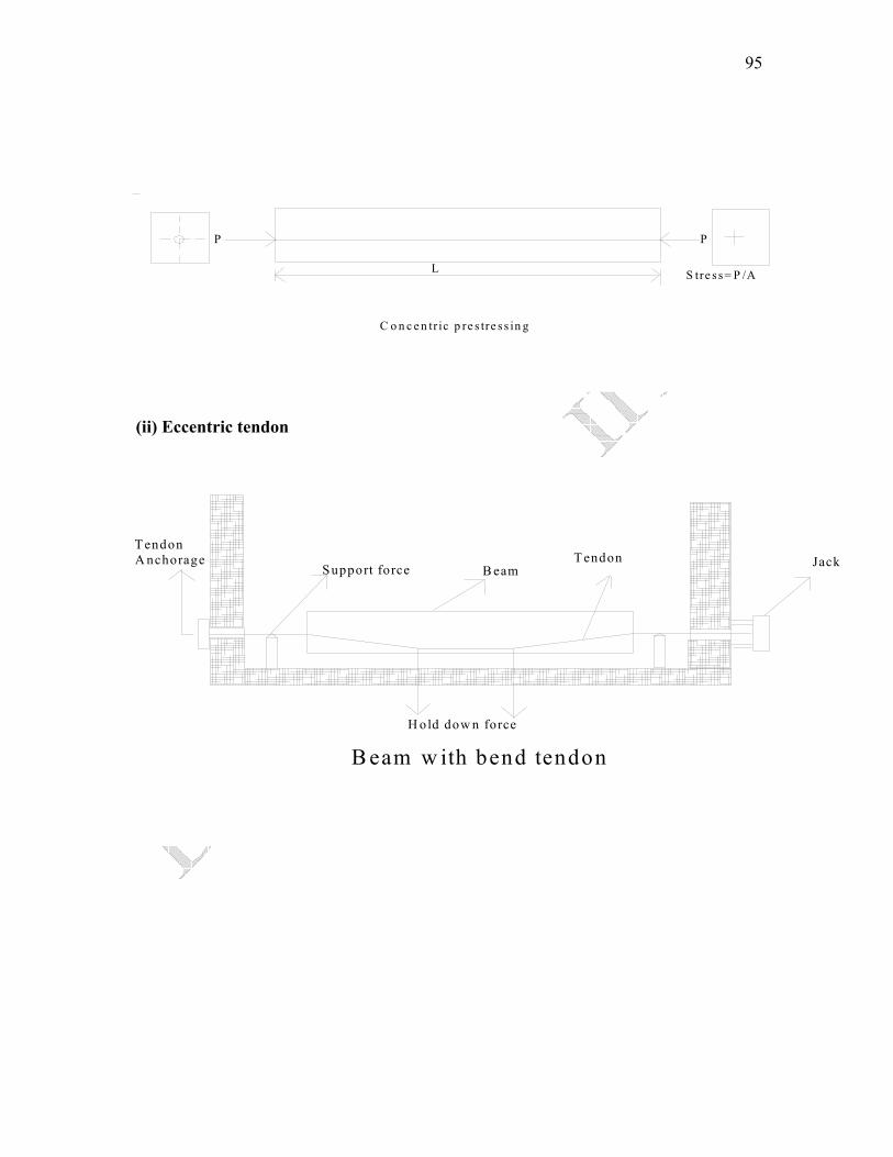
95
P
L S tre s s= P /A
P
C o n c e n tr ic p re s tre s s in g
(ii) Eccentric tendon
B eam w ith bend tendonH old dow n force
T endon A nchorage
Support forceT endon
B eamJack
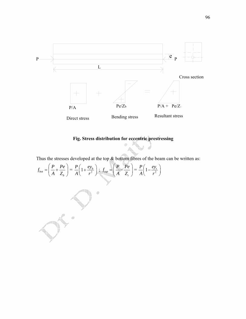
96
L
e P
Cross section
P/A
Direct stress
Pe/Zb
Bending stress
P/A + Pe/Z
Resultant stress
Fig. Stress distribution for eccentric prestressing
Thus the stresses developed at the top & bottom fibres of the beam can be written as:
botb
P PefA Z
⎛ ⎞= +⎜ ⎟⎝ ⎠
= 21 beyPA r⎛ ⎞+⎜ ⎟⎝ ⎠
topt
P PefA Z
⎛ ⎞= −⎜ ⎟⎝ ⎠
= 21 teyPA r⎛ ⎞−⎜ ⎟⎝ ⎠
;
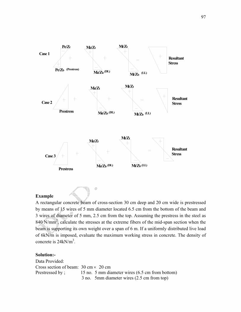
97
Case 1
Pe/Zt
Pe/Zb Md/Zb
Md/Zt
Ml/Zb
Ml/Zt
Resultant Stress
Md/Zb
Md/ZtMl/Zt
Ml/Zb
Ml/Zt
Md/ZbPrestress
Md/Zt
Ml/Zb
Resultant Stress
Resultant StressCase 3
(Prestress)(DL) (LL)
(DL) (LL)
(DL) (LL)Prestress
Case 2
Example A rectangular concrete beam of cross-section 30 cm deep and 20 cm wide is prestressed by means of 15 wires of 5 mm diameter located 6.5 cm from the bottom of the beam and 3 wires of diameter of 5 mm, 2.5 cm from the top. Assuming the prestress in the steel as 840 N/mm2, calculate the stresses at the extreme fibers of the mid-span section when the beam is supporting its own weight over a span of 6 m. If a uniformly distributed live load of 6kN/m is imposed, evaluate the maximum working stress in concrete. The density of concrete is 24kN/m3. Solution:- Data Provided: Cross section of beam: 30 cm × 20 cm Prestressed by ; 15 no. 5 mm diameter wires (6.5 cm from bottom) 3 no. 5mm diameter wires (2.5 cm from top)

98
Prestress in steel: 840 N/mm2 Span of the beam: 6 m Density of concrete: 24 kN/mm2
LL=6kN/m
6 m 300 mm
y
200 mm
65 mm
25 mm
Distance of the centroid of prestressing force from the base
( ) ( )⎟⎠⎞
⎜⎝⎛ ×+×
=18
27536515y =100mm
Eccentricity, e = 150-100= 50 mm Prestressing force, P = N ( ) 51037.1918840 ×=××Area of concrete section, A = (300 × 200) = 45×105mm2
Second moment of area, I = 200×3003/12 = 45×107mm4
Section modulus (Zt & Zb) = (45×107/150)=3×106 mm3
Self weight of the beam = (0.2×0.3×24) = 1.44kN/m
⎟⎟⎠
⎞
⎝
⎛ ×8
644.1 2
⎜⎜ = 6.48 kNm Moment due to self weight, Md =
⎟⎟⎠
⎞
⎝
⎛ ×866 2
⎜⎜ = 27kNm Live load Moment Ml =
⎟⎟⎠
⎞⎜⎜⎝
⎛××
=⎟⎠⎞
⎝ 4
5
106103
AP
⎜⎛ = 5N/mm2Direct stress due to prestress
Bending stress due to prestress ⎟⎟⎠
⎞⎜⎜⎝
⎛×
××=⎟
⎠⎞
⎜⎝⎛
6
5
10350103
ZPe = 5N/mm2
Self weight stress, 6
6
6.48 103 10
dMZ
⎛ ⎞×= ⎜ ×⎝ ⎠
⎟ = 2.16 N/mm2
Live load stress 6
6
27 103 10
lMZ
⎛ ⎞×= ⎜ ×⎝ ⎠
⎟ = 9N/mm2
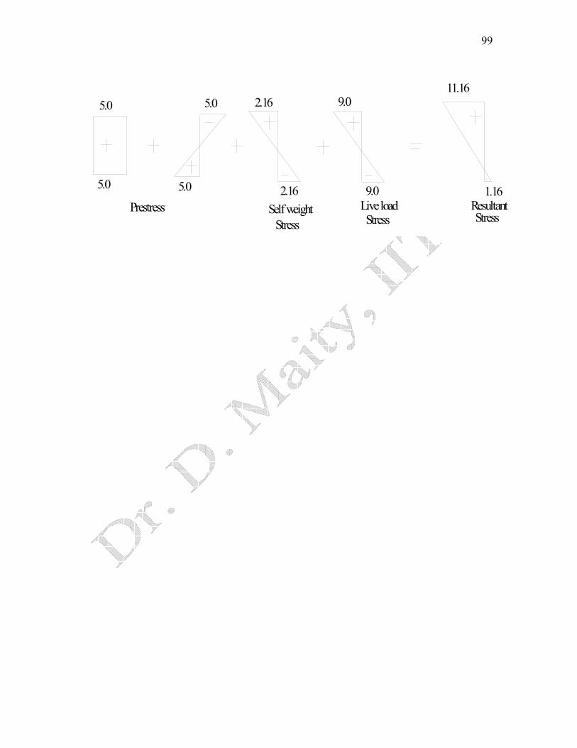
The resultant working stresses due to (self weight + prestress + LL) in the concrete =11.16N/mm2 (compressive) and 1.16N/mm2 (tensile)
99
5.05.0
Prestress
5.0 5.0
StressLive load9.02.16
Self weightStress
2.16 9.0
1.16ResultantStress
11.16
100
Lecture Note – 19
Losses in Prestress -I The initial prestressing concrete undergoes a gradual reduction with time from the stages of transfer due to various causes. This is generally defined as total “Loss of Prestress”. The various losses are explained below: Types of losses in prestress Pretensioning
1. Elastic deformation of concrete 2. Relaxation of stress in steel 3. Shrinkage of concrete 4. Creep of concrete
Post-tensioning
1. No loss due to elastic deformation if all wires are simultaneously tensioned. If the wires are successively tensioned, there will be loss of prestress due to elastic deformation of concrete.
2. Relaxation of stress in steel 3. Shrinkage of concrete 4. Creep of concrete 5. Friction 6. Anchorage slip
Loss due to elastic deformation of the concrete The loss of prestress due to deformation of concrete depends on the modular ratio & the average stress in concrete at the level of steel. If
cf Prestress in concrete at the level of steel
sE Modulus of elasticity of steel
cE Modulus of elasticity of concrete
eα Modular ratio
Strain in concrete at the level of steel =c
c
Ef
Stress in steel corresponding to this strain = sc
c EEf
101
Therefore, Loss of stress in steel = eα cf
If the initial stress in steel is known, the percentage loss of stress in steel due to elastic deformation of concrete can be computed. Example 1: (Elastic deformation) A pre-stressed concrete beam, 100 mm wide and 300 mm deep, is pre-tensioned by straight, wires carrying an initial force of 150kN at an eccentricity of 50 mm. The modulus of elasticity of steel and concrete are 210 and 35 kN/mm2 respectively. Estimate the percentage loss of stress in steel due to elastic deformation of concrete if the area of steel wires is 188 mm2. Solution: Here, Force, kN ; Eccentricity, e = 50 mm 150=P Area of concrete section, ( ) 4100 300 3 10A = × = ×
6225 10I = ×
mm2
Area of the steel wire = 188 mm2
Section modulus, mm4
Modular ratio, =eαs
c
EE
⎛⎜⎝ ⎠
⎞⎟ = 6
= cfPA
+b
P PeA Z+
⎝ ⎠
⎛ ⎞⎜ ⎟
3150 10800
188⎞×=⎟
⎝ ⎠
⎛⎜ N/ mm2Initial stress in steel =
3 3
4 6
150 10 150 10 50 503 10 225 10cf
⎛ ⎞ ⎛ ⎞× × × ×= + =⎜ ⎟ ⎜ ⎟× ×⎝ ⎠ ⎝ ⎠
6.66 N/ mm2Stress in concrete,
Loss of stress due to elastic deformation of concrete= ( )66.66×=ce fα 40 N/mm= 2
Percentage loss of stress in steel = 00
40 1005
800×⎛ ⎞ =⎜ ⎟
⎝ ⎠
Loss due to shrinkage of concrete Factors affecting the shrinkage in concrete
1. The loss due to shrinkage of concrete results in shortening of tensioned wires & hence contributes to the loss of stress.
2. The shrinkage of concrete is influenced by the type of cement, aggregate & the method of curing used.
3. Use of high strength concrete with low water cement ratio results in reduction in shrinkage and consequent loss of prestress.

102
4. The primary cause of drying shrinkage is the progressive loss of water from concrete.
5. The rate of shrinkage is higher at the surface of the member. 6. The differential shrinkage between the interior surfaces of large member may
result in strain gradients leading to surface cracking. Hence, proper curing is essential to prevent cracks due to shrinkage in prestress members. In the case of pretensioned members, generally moist curing is restored in order to prevent shrinkage until the time of transfer. Consequently, the total residual shrinkage strain will be larger in pretensioned members after transfer of prestress in comparison with post-tensioned members, where a portion of shrinkage will have already taken place by the time of transfer of stress. This aspect has been considered in the recommendation made by the code (IS:1343) for the loss of prestress due to shrinkage of concrete and is obtained below: If
6300 10−×
( )
csε Total residual shrinkage strain= for pre-tensioning and
= 6
10
200 10log 2t
−⎡ ⎤×⎢ ⎥
+⎢ ⎥⎣ ⎦
scs E
for post-tensioning.
Where, t Age of concrete at transfer in days.
Then, the loss of stress = ε
Here, Modulus of elasticity of steel sE
Example 2: (Shrinkage) A concrete beam is pre-stressed by a cable carrying an initial pre-stressing force of 300kN. The cross-sectional area of the wires in the cable is 300 mm2. Calculate the percentage loss of stress in the cable only due to shrinkage of concrete using IS: 1343 recommendations assuming the beam to be, (a) pre-tensioned and (b) post-tensioned. Assume Es = 210 kN/mm2 and age of concrete at transfer = 8 days. Solution:
Initial stress in wires =3300 10
1000300
⎛ ⎞×=⎜ ⎟
⎝ ⎠ N/mm2
(a) If the beam is pre-tensioned, the total residual shrinkage strain = units 6300 10−×
∴Loss of stress ( ) ( )−= ε ⋅ = × × =6 3300 10 210 10 63cs sE N/mm2

103
Percentage loss of stress = 00
63100 6.3
1000⎛ ⎞× =⎜ ⎟⎝ ⎠
(b) If the beam is post-tensioned, the total residual shrinkage strain
( )
6
10
200 10log 2cs t
−⎛ ⎞×ε = ⎜ ⎟⎜ ⎟+⎝ ⎠
( )
66
10
200 10200 10
log 8 2
−−
⎛ ⎞×= =⎜ ⎟⎜ ⎟+⎝ ⎠
× units
∴ Loss of stress = ( ) ( )6 3200 10 210 10 42cs sE −ε ⋅ = × × = N/mm2
Percentage loss of stress = 00
42100 4.2
1000⎛ ⎞× =⎜ ⎟⎝ ⎠
Loss due to creep of concrete The sustained prestress in the concrete of a prestress member results in creep of concrete which is effectively reduces the stress in high tensile steel. The loss of stress in steel due to creep of concrete can be estimated if the magnitude of ultimate creep strain or creep-coefficient is known.
1. Ultimate Creep strain method
sccc Efε The loss of stress in steel due to creep of concrete =
Where, ccε Ultimate creep strain for a sustained unit stress.
cf Compressive stress in concrete at the level of steel
sE Modulus of elasticity of steel
2. Creep Coefficient Method
Creep coefficient =e
c
strainElasticstrainCreep
εε
=
Therefore, loss of stress in steel = cc s e s s c e
c
fE E EE
fε φε φ φ α⎛ ⎞
= = =⎜ ⎟⎝ ⎠
Where, φ Creep Coefficient
Creep strain cε
Elastic strain eε
eα Modular ratio
cf Stress in concrete
cE Modulus of elasticity of concrete
sE Modulus of elasticity of steel

104
The magnitude of creep coefficient varies depending upon the humidity, concrete quality, duration of applied loading and the age of concrete when loaded. The general value recommended varies from 1.5 for watery situation to 4.0 for dry conditions with a relative humidity of 35%. Example 3: (Creep) A concrete beam of rectangular section, 100 mm wide and 300 mm deep, is pre-stressed by five wires of 7 mm diameter located at an eccentricity of 50 mm, the initial stress in the wires being 1200 N/mm2. Estimate the percentage loss of stress in steel due to creep of concrete using the ultimate creep strain method and the creep coefficient method (IS: 1343-1980). Use the following data: Solution: Here, kN/mm210sE = 2; 35cE = kN/mm2 ; mm6225 10I = × 4 ;
Ultimate creep strain mm/mm per N/mm61041 −×=ccε 2
Creep coefficient (φ ) = 1.6 ;
Prestressing force, P= ( ) 4102312005.5 ×=××38 N
Area of concrete section, A=300×100=3 mm410×
e
2
s
c
EE
⎛ ⎞⎟
⎝ ⎠ Modular ratio,α = ⎜ = 6
Stress in concrete at the level of steel is given by
4 4
4 6
23 10 23 10 50 5010.2
3 10 225 10cf⎡ ⎤⎛ ⎞× × × ×
= + =⎢ ⎥⎜ ⎟× ×⎢ ⎥⎝ ⎠⎣ ⎦ N/mm2
Ultimate Creep Strain Method
Loss of stress in steel = cc c sf Eε ⋅ ⋅ ( ) ( ) ( )6 341 10 10.2 210 10 88−= × × = N/mm2 ∴
Creep Coefficient Method Loss of stress in steel c ef= φ ⋅ ⋅ α ( )1.6 10.2 6 97.92= × × = N/mm2∴

105
Lecture Note – 20
Losses in Prestress -II
Loss due to relaxation of stress in steel Most of the codes provide for the loss of stress due to relaxation of steel as a percentage of initial stress in steel. The BIS recommends a value varying from 0 to 90 N/mm2 for stress in wires varying from to puf5.0 puf8.0
Where, Characteristic strength of pre-stressing tendon. puf
Loss of stress due to friction The magnitude of loss of stress due to friction is of following types: -
a. Loss due to curvature effect, which depends upon the tendon form or alignment, which generally follows a curved profile along the length of the beam.
b. Loss of stress due to wobble effect, which depends upon the local deviations in the alignment of the cable. The wobble or wave effect is the result of accidental or unavoidable misalignment, since ducts or sheaths cannot be perfectly located to follow a predetermined profile throughout the length of beam.
C a b le
P xPP
x L ?
( )kxox ePP +−= µα
Where,
oP The Prestressing force at the jacking end.
µ Coefficient of friction between cable and duct α The cumulative angle in radians through the tangent to the cable profile has
turned between any two points under consideration. k Friction coefficient for wave effect.

106
The IS code recommends the following value for k k = 0.15 per 100 m for normal condition
= 1.5 per 100 m for thin walled ducts where heavy vibration are encountered and in other adverse conditions.
Example 4 (friction) A concrete beam of 10 m span, 100 mm wide and 300 mm deep, is pre-stressed by 3 cables. The area of each cable is 200 mm2 and the initial stress in the cable is 1200 N/mm2. Cable 1 is parabolic with an eccentricity of 50 mm above the centroid at the supports and 50 mm below at the center of span. Cable 2 is also parabolic with zero eccentricity at supports and 50 mm below the centroid at the center of span. Cable 3 is straight with uniform eccentricity of 50 mm below the centroid. If the cables are tensioned from one end only, estimate the percentage loss of stress in each cable due to friction. Assume = 0.35 and k= 0.015 per m. µ
( ) ( )= −24ey L x
L Equation of parabola is given by:
( ) ( ) ( )24 42dy e eL xdx LL
= − =Slope at ends (at ) 0x = =
Solution:
Here, Given Equation of parabola: ( ) ( )= −24ey L x
L
0x
( ) ( ) ( )24 42dy e eL xdx LL
= − = Slope at ends (at = ) =
For cable 1 e = 100 mm
Slope at end = 4 10010 1000
×⎛ ⎞⎜ ⎟×⎝ ⎠
=0.04
∴ Cumulative angle between tangents, α = 2 0.04 0.08× = radians For cable 2 e = 50 mm
Slope at end ⎟⎠⎞
⎜⎝⎛
××100010504 =0.02
∴ Cumulative angle between tangents, α 2 0.02 0.04= × = radians
Initial pre-stressing force in each cable, ( )0 200 1200 24,0000P = × = N

107
If pre-stressing force (stress) in the cable at the farther end, xP =( )kx
x oP P e µα− +=For small values of ( )µα + kx , we can write
( )1xP P kxµα⎡ ⎤= − +⎣ ⎦
Loss of stress ( )= µα +0P kx
Cable 1 ( )0 00.35 0.08 0.0015 10 0.043P P= × + × =
Cable 2 ( )0 00.35 0.04 0.0015 10 0.029P P= × + × =
Cable 3 ( )0 00 0.0015 10 0.015P P= + × =
If Initial stress OP = = 1200 N/mm2
Cable No Loss of stress, kN/mm2 Percentage loss
1 51.6 4.3 2 34.8 2.9 3 18.0 1.5
Loss due to Anchorage slip The magnitude of loss of stress due to the slip in anchorage is computed as follows: - If Slip of anchorage, in mm ∆
L Length of the cable, in mm A Cross-sectional area of the cable in mm2 Es Modulus of elasticity of steel in N/mm2
P Prestressing force in the cable, in N
sAEPL
=∆ Then,
Hence, Loss of stress due to anchorage slip = L
EAP s∆= ;
Example 5:(Anchorage slip) A concrete beam is post-tensioned by a cable carrying an initial stress of 1000 N/mm2. The slip at the jacking end was observed to be 5 mm. The modulus of elasticity of steel is 210 kN/mm2. Estimate the percentage loss of stress due to anchorage slip if the length of the beam is 30 m. Solution:
∴ Loss of stress due to anchorage slip = sEL∆⎛ ⎞
⎜ ⎟⎝ ⎠
108
= ( ) ( )3210 10 5
3530 1000
×=
× N/mm2
Percentage loss of stress = 00
35100 3.5
1000× =
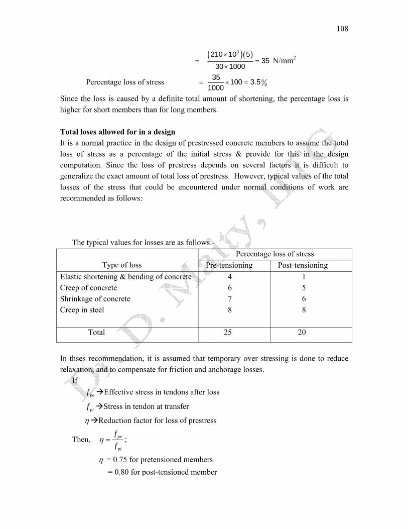
Since the loss is caused by a definite total amount of shortening, the percentage loss is higher for short members than for long members. Total loses allowed for in a design It is a normal practice in the design of prestressed concrete members to assume the total loss of stress as a percentage of the initial stress & provide for this in the design computation. Since the loss of prestress depends on several factors it is difficult to generalize the exact amount of total loss of prestress. However, typical values of the total losses of the stress that could be encountered under normal conditions of work are recommended as follows:
The typical values for losses are as follows:-
Percentage loss of stress Type of loss Pre-tensioning Post-tensioning Elastic shortening & bending of concrete Creep of concrete Shrinkage of concrete Creep in steel
4 6 7 8
1 5 6 8
Total 25 20
In thses recommendation, it is assumed that temporary over stressing is done to reduce relaxation, and to compensate for friction and anchorage losses.
If Effective stress in tendons after loss pef
Stress in tendon at transfer pif
η Reduction factor for loss of prestress
Then, pe
pi
ff
η = ;
η = 0.75 for pretensioned members = 0.80 for post-tensioned member

109
Lecture Note – 21
Pressure line or thrust line
In prestress, the combined effect of prestressing force & external load can be resolved into a single force. The locus of the points of application of this force in any structure is termed as the pressure line or thrust line. The load here is such that stress at top fiber of support & bottom fiber of the central span is zero. Let us consider a beam which is prestressed by a force P at a constant eccentricity e. The magnitude of load & eccentricity is such that the stress at the bottom fiber at the mid span is zero. It is possible if the eccentricity is e = d/6 it can be seen from the resultant stress distribution at the support due to a prestressing force P at an eccentricity e = d/6 & bending moment zero is equivalent to a force P applied at an eccentricity e = d/6. At quarter span the resultant stress distribution due force P applied at an eccentricity e = d/12. Similarly, at mid span the resultant stress distribution due to a force P at an eccentricity e = d/6 & BM due to uniformly distributed load is equivalent to a force P applied at an eccentricity e = -d/6.
e=d/6P
e=d/6
LL/2
L/4
Pressure line
Cable line
e=d/12
At support, x = 0
0P M yA I− =
3
21
12
dP ePbd bd
⋅ ⋅⇒ =
e = d/6
P
6de∴ = x=0
110
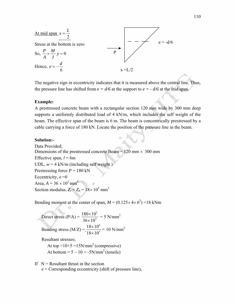
At mid span 2Lx =
e = -d/6 Stress at the bottom is zero
So, 0P M yA I+ = P
Hence, 6de −=
x =L/2 The negative sign in eccentricity indicates that it is measured above the central line. Thus, the pressure line has shifted from e = d/6 at the support to e = - d/6 at the mid span. Example: A prestressed concrete beam with a rectangular section 120 mm wide by 300 mm deep supports a uniformly distributed load of 4 kN/m, which includes the self weight of the beam. The effective span of the beam is 6 m. The beam is concentrically prestressed by a cable carrying a force of 180 kN. Locate the position of the pressure line in the beam. Solution:- Data Provided; Dimensions of the prestressed concrete Beam = 120 mm × 300 mm Effective span, l = 6m UDL, w = 4 kN/m (including self weight.) Prestressing force P = 180 kN Eccentricity, e =0 Area, A = 36 ×103 mm2
Section modulus, Zt = Zb = 18×105 mm3
Bending moment at the center of span, M = (0.125×4×62) =18 kNm
Direct stress (P/A) = 3
3
180 1036 10
××
= 5 N/mm2
Bending stress (M/Z) = 6
5
18 1018 10××
= 10 N/mm2
Resultant stresses; At top =10+5 =15N/mm2 (compressive) At bottom = 5 – 10 = -5N/mm2 (tensile) If N = Resultant thrust in the section e = Corresponding eccentricity (shift of pressure line),

111
then N/A +Ne/Z = 15 But, N = 180 kN, A= 36×103 mm2 and Z= 18×105mm3
Solving the above equation, e = 100mm;
Direct stress Bending stress Resultant stress
5
5
1510
10
N/mm2
N/mm2
Pressure line
P
Cable line
100mm
6m
P
Fig. Location of pressure line in prestressed beam
Example:- A prestressed concrete beam of section 120 mm wide by 300 mm deep is used over an effective span of 6 m to support a uniformly distributed load of 4 kN/m, which includes the self weight of the beam. The beam is prestressed by a straight cable carrying a force of 180 kN & located at an eccentricity of 50 mm. Determine the location of the thrust-line in the beam and plot its position at quarter and central span sections. Solution:- Here, Given P = 180 kN ; e = 50 mm A = mm31036× 2 ; Z = mm51018× 3
At Central Span Section:
112
Prestress due to direct stress ⎟⎟⎠
⎞⎜⎜⎝
⎛××
=⎟⎠⎞
⎜⎝⎛
3
3
103610180
AP = 5 N/mm2
Prestress due to bending ⎟⎟⎠
⎞⎜⎜⎝
⎛×
××=⎟
⎠⎞
⎜⎝⎛
5
3
10185010180
ZPe = 5 N/mm2
BM at the centre = 864 2× =18 kNm
Bending stresses at the top and bottom =± ⎟⎟⎠
⎞⎜⎜⎝
⎛××
5
6
10181018 = ±10 N/mm2
Resultant stresses at the central section: At Top = (5 – 5 + 10) = 10 N/mm2
At bottom = (5 + 5 - 10) = 0 N/mm2
Shift of pressure line from cable line =M/P =6
4
18 1018 10⎛ ⎞×⎜ ×⎝ ⎠
⎟ = 100 mm
At Quarter Span Section: BM at quarter span section = (3/32) ql2 = 13.5 kNm.
⎟⎟⎠
⎞
⎝
⎛××
4
6
1018105.13
⎜⎜ = 7.5 N/mm2 Bending stresses at the top and bottom =
Resultant stresses at the quarter span section: At Top = (5 – 5 + 7.5) = 7.5 N/mm2
At bottom = (5 + 5 – 7.5) = 2.5 N/mm2
6
4
13.5 1018 10
⎛ ⎞×⎟×⎝ ⎠
Shift of pressure line from cable line =M/P =⎜ = 75 mm
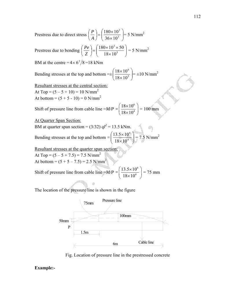
The location of the pressure line is shown in the figure
Pressure line
P50mm
75mm
Cable line
100mm
1.5m
6m
Fig. Location of pressure line in the prestressed concrete
Example:-

113
A rectangular concrete beam 250 mm wide by 300 mm deep is prestressed by a force of 540 kN at a constant eccentricity of 60 mm.The beam supports a concentrated load of 68 kN at the centre of the span of 3 m. Determine the location of the pressure line at the centre, quarter span and support sections of the beam. Neglect the self weight of the beam. Solution:- Here, Given
2250 3006×P = 540 kN; A = (250×300) = ( )310375× mm2; e = 60 mm; Z = =375 × 104
mm3
At the centre of the span = (0.25 qM ×68×3) = 51 kNm
At the quarter span = (0.125 qM × 68 × 3) = 25.5 kNm
Stresses due to prestressing force:
⎟⎟⎠
⎞⎜⎜⎝
⎛××
=⎟⎠⎞
⎝ 3
4
10751054
AP
⎜⎛ =7.2 N/mm2 Prestress due to direct stress
4
4
54 10 60375 10
PeZ
⎛ ⎞× ×= ⎜ ⎟×⎝ ⎠ ⎝ ⎠
⎛ ⎞⎜ ⎟ = 8.6 N/mm2 Prestress due to bending
Stresses due external loads
⎟⎟⎠
⎞⎜⎜⎝
⎛××
=⎟⎟⎠
⎞⎜⎜⎝
⎛4
6
103751051
ZM q = 13.6 N/mm2 At the centre of span
⎟⎟⎠
⎞⎜⎜⎝
⎛××
=⎟⎟⎠
⎞⎜⎜⎝
⎛4
6
10375105.25
ZM q = 6.8 N/mm2 At the quarter span
9
y2
2 .2
300m m
y1
12 .2 (N /m m 2)5 .4

114
The position of the resultant thrust from the top fibre of the beam is as follows:
( ) ( )⎥⎦⎤
⎢⎣⎡
+××+×
=1500660
10010300211502.23001y = 115 mm
( ) ( )⎥⎦⎤
⎢⎣⎡
+××+×
=5401620
2006.3300211504.53002y = 162 mm
Thus, the location of the pressure line will be as follows:
Pressure line
P
Cable line
35mm
3m
12mmP
Fig. Location of pressure line in the prestressed concrete

115
Lecture Note – 22 Concept of load balancing In the prestress concrete, it is possible to select cable profile in such a way that the transverse component of the cable force balances the given type of external loading. If in a parabolic prestressing tendon
maxe Maximum eccentricity
P Prestressing force Then the prestressing force may be considered as an upward uniformly distributed load. The maximum prestressing moment can be equated to the maximum BM due to upward uniformly distributed load on the beam. So
2
max8pw l
Pe=
max2
8p
Pewl
⇒ =
If w The downward load Then net load, 0 pw w w= −
20
8w lNet bending moment, M = =

116
Equivalent moment or Load
Equivalent loading CamberTendon profile
L
P P
PP
PP
P P
L
e
e
e
L/2 L/2
4PeW L=
WL/2 L/2
L
2
8PewL
=
PeW
aL=
45
384
wL
EI
L/2L/2
aLaL aL aL
L
w
W W
3
48WL
EI
C.G
C.G
C.G
( )2 33 424
a a WEI
−
L
e
2
8ML
EI M pe= C.G
M M
L
L
Example: (Load balancing concept)

117
A rectangular concrete beam 300 mm wide, 800 mm deep supports two concentrated loads of 20 kN each at third point of a span of 9 m.
a) Suggest a suitable cable profile. If eccentricity of the cable profile is 100 mm for middle third portion of the beam, calculate the prestressing force required to balance the bending effect of the concentrated loads neglecting the self weight.
b) For the same cable profile find effective force in cable if the resultant stress due to self wt., imposed load, and prestressing force is zero at the bottom fiber of mid span section.(Assume density of concrete = 24 kN/m3)
Solution:- Here given section = 300 mm × 800 mm; Span (L) = 9 m For (a) A trapezoidal cable profile is selected since the bending moment diagram is trapezoidal in shape.
e = 100 mm;
⎟⎠⎞
⎜⎝⎛=
3QLPe
⎟⎠⎞
⎜⎝⎛
××
=⎟⎠⎞
⎜⎝⎛=∴
1003900020
3eQLP =600 kN
For (b) Self wt of beam, g = (0.3×0.8×24) = 5.76 kN/m Self wt moment, Mg = (0.125×5.76×92) = 58.32 kNm
⎟⎟⎠
⎞
⎝
⎛××
6
6
10321032.58
⎜⎜ = 1.82 N/mm2Bending stress=
Moment at the center due to the loads = ⎟⎠⎞
⎜⎝⎛ ×
=⎟⎠⎞
⎜⎝⎛
3920
3QL = 60 kNm
Stresses due to loads = ⎟⎟⎠
⎞⎜⎜⎝
⎛××
6
6
10321060 = 1.875 N/mm2
Total tensile bending stress at the bottom fiber = 1.82 + 1.875 = 3.695 N/mm2
Let, P be required prestressing force in cable, e = 100 mm, Area of the concrete section, A =300×800=24×104 mm2
Thus, 695.3=+ZPe
AP ∴P = 507 kN.
Example:- (Concrete beam with over hang)
118
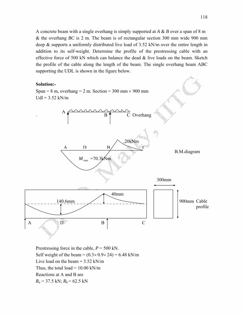
A concrete beam with a single overhang is simply supported at A & B over a span of 8 m & the overhang BC is 2 m. The beam is of rectangular section 300 mm wide 900 mm deep & supports a uniformly distributed live load of 3.52 kN/m over the entire length in addition to its self-weight. Determine the profile of the prestressing cable with an effective force of 500 kN which can balance the dead & live loads on the beam. Sketch the profile of the cable along the length of the beam. The single overhang beam ABC supporting the UDL is shown in the figure below. Solution:- Span = 8 m, overhang = 2 m. Section = 300 mm × 900 mm Udl = 3.52 kN/m A
B C Overhang `
20kNm A D B C
B.M.diagram M =70.3kNm max
300mm 300mm
A D B C
40mm 140.6mm Cable
profile 900mm
Prestressing force in the cable, P = 500 kN. Self weight of the beam = (0.3×0.9×24) = 6.48 kN/m Live load on the beam = 3.52 kN/m Thus, the total load = 10.00 kN/m Reactions at A and B are Ra = 37.5 kN; Rb = 62.5 kN
119
Mb = 0.5×10×22 = 20 kNm Bending moment at a distance x from a is
xM = 37.5× x - 0.5 ×10×x2
For maximum BM 0=dx
dM x ⇒ 37.5 -10x= 0
x = 3.75m Hence, maximum BM = 37.5 × 3.75 – 0.5 × 10 × 3.752 = 70.3 kNm
xM = 0, at x = 7.5 m [As, 5x2 – 37.5x = 0]
The eccentricity of the cable at the position of maximum BM is
e = ⎟⎠⎞
⎜⎝⎛
PM max =
6
3
70.3 10500 10
××
= 140.6 mm
Eccentricity at B, ⎟⎠⎞
⎜⎝⎛=
PM
e bb =
6
3
20 10500 10
××
= 40 mm
Since the bending moment at point A and C are zero, the cable is concentric at these points. The cable profile is parabolic with eccentricity of 140.6 mm below the centroidal axis at D and and 40 mm above the centroidal axis at support section B. Example:- A beam of symmetrical I-section spanning 8 m has a flange width of 150m m & flange thickness of 80 mm respectively. The overall depth of the beam is 450 mm. Thickness of the web is 80 mm. The beam is prestressed by a parabolic cable with an eccentricity of 150 mm at the centre of the span & zero at the supports. The LL on the beam is 2.5 kN/m. (a) Determine the effective force in he cable for balancing the DL & LL on the beams. (b) Sketch the distribution of resultant stress at the centre of span section for the above case. (c) Calculate the shift of the pressure line from the tendon–centre–line. Solution:- The properties of the I-section are as follows: Area of the section, 20.63A m= Moment of inertia, 9 41.553 10I mm= × Section modulus, mm66.9 10Z = × 3
Eccentricity, e = 150 mm
120
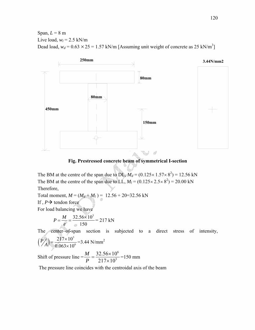
Span, L = 8 m Live load, wl = 2.5 kN/m Dead load, wd = 0.63 ×25 = 1.57 kN/m [Assuming unit weight of concrete as 25 kN/m3]
250mm
80mm
450mm
150mm
80mm
3.44N/mm2
Fig. Prestressed concrete beam of symmetrical I-section
The BM at the centre of the span due to DL, Md = (0.125×1.57×82) = 12.56 kN The BM at the centre of the span due to LL, Ml = (0.125×2.5×82) = 20.00 kN Therefore, Total moment, M = (Md + Ml ) = 12.56 + 20=32.56 kN If , P tendon force For load balancing we have
332.56 10150
MPe
×= = = 217 kN
The center–of-span section is subjected to a direct stress of intensity,
( )3
6
217 100.063 10
PA
×=
×=3.44 N/mm2
Shift of pressure line =6
332.56 10217 10
MP
×=×
=150 mm
The pressure line coincides with the centroidal axis of the beam
121
Lecture Note – 23 Deflections Factors influencing deflection:
1. Imposed load & self load 2. Magnitude of prestressing force 3. Cable profile 4. Second moment of area of cross-section 5. Modulus of elasticity of concrete 6. Shrinkage, creep & relaxation of steel stress 7. Span of the member 8. Fixity condition
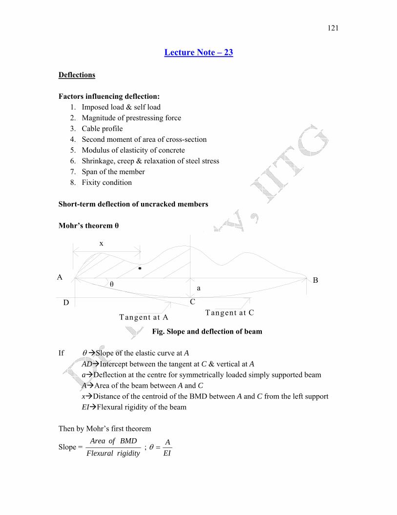
Short-term deflection of uncracked members Mohr’s theorem θ
D
A
x
B
If θ SloAD Ina DeflA Arex DistEI Fle
Then by Mohr’
Slope = FlexurArea
θ
T angent at A T angent at CC
a
Fig. Slope and deflection of beam
pe of the elastic curve at A tercept between the tangent at C & vertical at A ection at the centre for symmetrically loaded simply supported beam a of the beam between A and C ance of the centroid of the BMD between A and C from the left support xural rigidity of the beam
s first theorem
rigidityalBMDof
; EIA
=θ

122
According to Mohr’s second theorem
Intercept, a = rigidityFlexural
BMDofareaofmoment= ⎟
⎠⎞
⎜⎝⎛
EIAx
Effect of tendon profile on deflection
1. Straight tendon
BMD
L
e PP
a
Pe
If P Effective prestressing force e Eccentricity L Length of the beam
Then,
EI
LLPe ⎟⎠⎞
⎜⎝⎛⎟⎠⎞
⎜⎝⎛
− 42 = EI
PeL8
2
− Deflection, a =

123
2. Trapezoidal tendon
L
e P
L 1
23L 1
BM D Pe
a
L 1+L 2/2
P
L 2
Deflection, a = ( ) 12 1 2
1
2/ 22 3lPe l l l
EI l⎡ ⎤⎛ ⎞⎛ ⎞+ +⎢ ⎥⎜ ⎟⎜ ⎟
⎝ ⎠⎝ ⎠⎣ ⎦ = ( )2
2212
1
2
3628
llllEI
PeL++−
3. Parabolic tendons (Central Anchors)
a
58L/2
BMDPe
P
L
eP
Deflection, a = ⎥⎦⎤
⎢⎣⎡ ⋅⋅⋅
285
232 LL
EIPe = - ⎟⎟
⎠
⎞⎜⎜⎝
⎛EI
PeL485 2
124
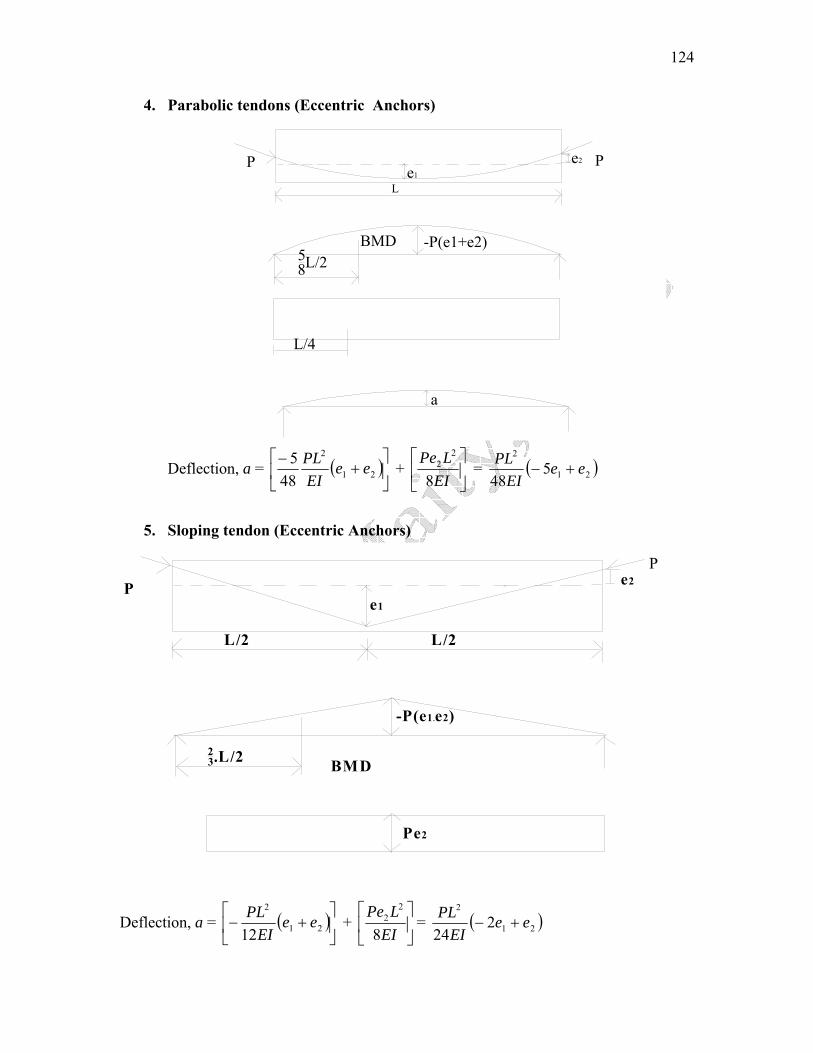
4. Parabolic tendons (Eccentric Anchors)
L
58L/2
a
-P(e1+e2)BMD
e1
e2P
L/4
P
Deflection, a = ( )⎥⎦
⎤⎢⎣
⎡+
−21
2
485 ee
EIPL + ⎥
⎦
⎤⎢⎣
⎡EI
LPe8
22 ( )21
2
548
eeEI
PL+− =
5. Sloping tendon (Eccentric Anchors)
PP
L/2 L/2
e1
e2
-P(e1.e2)
23.L/2 BMD
Pe2
Deflection, a = ( )⎥⎦
⎤⎢⎣
⎡+− 21
2
12ee
EIPL + ⎥
⎦
⎤⎢⎣
⎡EI
LPe8
22 = ( )21
2
224
eeEI
PL+−

125
6. Parabolic and straight Tendon
L 2L 1
L
eP P
( l 1 + l 2 / 2 )
B M DP e5 L 1 / 8
Deflection, a = 1 1 22 1
2 53 8 2l l lPe l l
EI⎡ ⎤⎛ ⎞⎛ ⎞ ⎛ ⎞+ +⎜ ⎟⎜ ⎟ ⎜ ⎟⎢ ⎥⎝ ⎠⎝ ⎠ ⎝ ⎠⎣ ⎦
= 2 21 1 2 25 12 6
12Pe l l l lEI
⎡ ⎤− + +⎣ ⎦
7. Parabolic & straight tendons (Eccentric Anchors)
Pe2
(l1+l2/2)
BMD -P(e1e2)
58L1
P
L
L2
Pe1
L1
Deflection, a = ( ) 21 2 2 2 2
1 1 2 25 12 612 8
P e e Pe Ll l l lEI E+
I⎡ ⎤
⎡ ⎤− + + + ⎢ ⎥⎣ ⎦⎣ ⎦
126
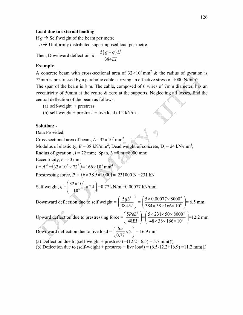
Load due to external loading If g Self weight of the beam per metre q Uniformly distributed superimposed load per metre
Then, Downward deflection, a = ( ) 45384g q L
EI+
Example A concrete beam with cross-sectional area of 32 mm310× 2 & the radius of gyration is 72mm is prestressed by a parabolic cable carrying an effective stress of 1000 N/mm2. The span of the beam is 8 m. The cable, composed of 6 wires of 7mm diameter, has an eccentricity of 50mm at the centre & zero at the supports. Neglecting all losses, find the central deflection of the beam as follows:
(a) self-weight + prestress (b) self-weight + prestress + live load of 2 kN/m.
Solution: - Data Provided; Cross sectional area of beam, A= 32 mm310× 2
Modulus of elasticity, E = 38 kN/mm2; Dead weight of concrete, Dc = 24 kN/mm3; Radius of gyration , i = 72 mm; Span, L =8 m =8000 mm; Eccentricity, e =50 mm I = Ai2 = ( ) 623 10166721032 ×=××
)mm4
Prestressing force, P = ( =×× 10005.386 231000 N =231 kN
⎟⎟⎠
⎞⎜⎜⎝
⎛×
× 2410
10326
3
Self weight, g = =0.77 kN/m =0.00077 kN/mm
Downward deflection due to self weight = ⎟⎟⎠
⎞⎜⎜⎝
⎛EI
gL3845 4
= ⎟⎟⎠
⎞⎜⎜⎝
⎛×××
××6
4
1016638384800000077.05 = 6.5 mm
Upward deflection due to prestressing force = ⎟⎟⎠
⎞⎜⎜⎝
⎛EI
PeL485 4
= ⎟⎟⎠
⎞⎜⎜⎝
⎛×××
×××6
4
1016638488000502315 =12.2 mm
Downward deflection due to live load = ⎟⎠⎞
⎜⎝⎛ × 2
77.05.6 = 16.9 mm
(a) Deflection due to (self-weight + prestress) =(12.2 - 6.5) = 5.7 mm(↑) (b) Deflection due to (self-weight + prestress + live load) = (6.5-12.2+16.9) =11.2 mm(↓)