Embed Size (px)
Citation preview
Previously Published in Proceedings, Texas Section ASCE Fall Meeting, September 29-August 2, 2004, Houston, Texas
Comparison of Methods of Estimating Prestress Losses for Bridge Girders by Scott Walton, M.S.C.E., E.I.T.1 and Timothy E. Bradberry, M.S.E., P.E.2
ABSTRACT A new method for estimating prestress losses has been published in NCHRP Report 496, Prestress Losses in Pretensioned High-Strength Concrete Bridge Girders. The new procedure, which is the basis of provisional changes to be published in the 2005 Interim Revisions of the 2004 AASHTO LRFD Bridge Design Specifications, Section 5.9.5, “Loss of Prestress,” is significantly more complex and calculation intensive than that of the current design specifications. The authors compare the two prestress loss estimation methods and compare the results of the proposed detailed loss calculation procedure with the results of the current AASHTO LRFD loss calculation procedure for three prestressed concrete bridge girders, representing a range of typical bridge girders. The authors include a discussion of how use of transformed section properties (i.e. include prestressing steel as part of the composite section resisting loads and deformation) affects procedurally and numerically the estimation of elastic losses and gains.
INTRODUCTION With today’s desktop computing power, engineering equations that were created to
simplify complex relationships and make hand designs possible are being replaced by much more calculation intensive equations and procedures that are presumed to be more accurate. These new procedures are being incorporated into design specifications, simply because the technology exists to implement them in the design process. The implementation of these state-of-the-art procedures essentially requires design engineers to either purchase or develop software, and learn how to use it, in order to be competitive. This is assumed to be a good thing. However, in the case of loss of prestress, if the design engineer really believes that the prestress losses and girder stresses that an AASHTO LRFD Bridge Design Specifications (2004) 3 compliant computer program calculates are in any way exact, such an implementation would be unfortunate. Also, if the design engineer feels that the prestress loss provisions of the design specifications are too complicated to implement by hand s/he may feel pressured by work load to forgo understanding the provisions and instead may blindly accept the computer analysis as fact without developing any engineering judgment as to the limitations of the provisions. This too would be unfortunate. Together, these two unfortunate possibilities could result in a compromise of the economy, constructability, and/or the serviceability of a prestressed concrete bridge. In rare cases the safety of such a bridge may also be at risk. 1 Engineering Assistant, Bridge Division, Texas Department of Transportation, 125 East 11th Street, Austin, Texas 78701-2483; voice: (512) 416-2554; fax: (512) 416-2354; e-mail: [email protected],tx.us. 2 Support Branch Manager, Bridge Division, Texas Department of Transportation, 125 East 11th Street, Austin, Texas 78701-2483; voice: (512) 416-2179; fax: (512) 416-2354; e-mail: [email protected],tx.us. 3 American Association of State Highway and Transportation Officials: “AASHTO-LRFD Bridge Design Specifications.” (2004)
1
Previously Published in Proceedings, Texas Section ASCE Fall Meeting, September 29-August 2, 2004, Houston, Texas
The Modified Compression Field Theory (MCFT) for shear design of structural concrete, as implemented in the AASTHO LRFD Specifications, requires iteration of a family of somewhat complex formulae and is another example of a complicated design procedure that lends itself to computerization but not to human intuition (excepting the opinion of the small band of engineers involved in its development). While such analysis and design methods as the new prestress loss provisions and the MCFT shear provisions may be difficult to use or understand, many of these improvements are thought to allow engineers to design more efficient structures while maintaining uniform structural reliability.
Recent research performed as part of NCHRP Project 18-07 (FY 1999), “Prestress Losses in Pretensioned High-Strength Concrete Bridge Girders,” resulted in the development of revised calculations which allow for more “accurate” predictions of concrete modulus of elasticity, creep, shrinkage, camber, and prestress losses. The results of this research are published in NCHRP Report 496, Prestress Losses in Pretensioned High-Strength Concrete Bridge Girders.4 The purportedly more accurate prestress loss predictions come at a significant price, however. There is an increased procedural complexity of the calculations. While the calculations are more complex than the current provisions they may still be performed by hand, but are more efficiently implemented with a computer spreadsheet or other computer based tool. The recommendations of NCHRP Report 496 have been affirmatively voted into the provisions of the 2005 Interim Revisions to the AASHTO LRFD Bridge Design Specification by the AASHTO Standing Committee on Bridges and Structures (SCOBS), replacing the refined method in the current specifications. Since the practicing design engineer has no choice but to implement provisions of design codes or specifications when designing applicable structures some explanation of this substantially different method is warranted. The authors are not familiar with any explanation of the implementation of the NCHRP Report 496 procedures that they would consider satisfactory to the practicing bridge design engineer. The following is intended to provide such an explanation.
THE ANATOMY OF PRESTRESS LOSSES The hand calculation procedures for estimating loss of prestress have evolved over the
fifty-four year history of the precast prestressed concrete industry in the United States from simple lump sums, such as the 35,000 psi for losses from “all causes except friction,” which was specified in the 1961 edition of the AASHO Standard Specifications for Highway Bridges, to the complex design procedures of NCHRP Report 496. During that time period, virtually the entire United States Interstate Highway System was built (and a significant amount of lane miles added or rebuilt) with a large part of that construction utilizing precast prestressed concrete and with very few, if any, significant problems traced to designer engineers’ “inaccurate” prestress loss calculations. At least, that has been the experience in Texas. It is highly probable that if hand calculation procedures where still employed in bridge design offices, rather than digital computer aided design procedures, the simple prestress losses estimation procedures of a decade or so ago could continue to be employed to design safe and serviceable precast prestressed concrete members for as long as concrete and prestressing steel materials remained similar in characteristics to the materials used regularly today. Nonetheless, in this section the authors
4 Tadros, Al-Omaishi, Seguirant, and Gallt: Prestress Losses in Pretensioned High-Strength Concrete Bridge Girders. (2003)
2
Previously Published in Proceedings, Texas Section ASCE Fall Meeting, September 29-August 2, 2004, Houston, Texas
discuss state-of-the-art prestress loss calculation procedures along with the phenomenon of each loss component, thus exposing the anatomy of prestress losses.
LRFD Refined Method The 2004 AASHTO LRFD Bridge Design Specifications allow for three different
methods to compute prestressed losses—the lump sum method, the refined method, and the time step method. The lump sum method involves using a single equation to estimate time dependant losses. This equation is a function of the partial prestressing ratio, and in some cases the final concrete strength, . The refined method uses a separate equation for each of the different, interdependent components of the time dependant losses—shrinkage, creep, and relaxation. The most significant change in the loss calculation between the current AASHTO LRFD Specifications and those proposed in NCHRP Report 496 are to the refined loss estimate equations. These equations are therefore discussed in more detail in the appropriate sections below.
cf '
The specifications contain no guidance for, or mention of, the time step method. They instead refer to a “more detailed analysis”, which is typically a time step method. In a time step analysis, the life of the prestressed concrete girder is divided into small steps, over which the strain in the concrete and steel are assumed to be constant. Knowing the conditions at the beginning of the step, the total loss due to creep, shrinkage, and relaxation over a given time interval can be determined. This process is repeated for each step, and the sum of the losses over each step yields the total time dependant loss. The time step method will not change with the incorporation of the NCHRP Report 496 procedures into the specifications; however, the values used for ultimate creep strain and ultimate shrinkage will change.
NCHRP Report 496 Method The NCHRP Report 496 prestress loss calculation method falls somewhere between the
time step method and the refined method in the AASHTO LRFD Specifications. Losses are calculated by summing components, just as in the refined method, but the time-dependant losses are now calculated in stages, from release to deck placement and from deck placement to final. The main loss equations are:
pLTpESpT fff ∆+∆=∆ (LRFD 5.9.5.1-1)
dfpSSpRpCRpSRidpRpCRpSRpLT ffffffff )()( 32 ∆−∆+∆+∆+∆+∆+∆=∆ (LRFD 5.9.5.4.1-1) where:
pESf∆ is the sum of all losses or gains due to elastic shortening or extension at the time of application of prestress and/or external loads (ksi)
idpRpCRpSR fff )( 2∆+∆+∆ is the sum of all time dependant losses between release and deck placement (ksi)
dfpSSpRpCRpSR ffff )( 3 ∆−∆+∆+∆ is the sum of all time dependant losses between deck placement and final (ksi)
3
Previously Published in Proceedings, Texas Section ASCE Fall Meeting, September 29-August 2, 2004, Houston, Texas
Not only have the overall loss equations for the refined method changed, but the equations for each of the individual loss components have also changed, as well as those for the modulus of elasticity, shrinkage strain, creep coefficient, and the lump sum estimate for I beams. An in-depth description and explanation of each of these changes and reasons for them is beyond the scope of this paper. The authors refer the reader to NCHRP Report 496 for more information on items not covered herein.
The NCHRP Report 496 approach to the calculation of prestress losses for high strength concrete, as published, is dependent to a large degree on the modulus of elasticity, creep coefficient, and shrinkage of the concrete. These concrete material properties are in turn dependent on local concrete constituent materials and mix design practices. Similarly, TxDOT Research Report 381-1, “Time Dependant Deflections of Pretensioned Beams,”5 (a report of TxDOT Research Study 3-5-84-381-1) proposes a camber prediction procedure that would benefit from a more refined characterization of the instantaneous and time dependant behavior of concrete used in the production of prestressed concrete bridge beams from disparate locations in Texas. Recent research has also highlighted the relationship between aggregate properties in a concrete mix and the modulus of elasticity of the concrete.6 For this reason, the authors have submitted to TxDOT’s Research and Technology Implementation office a research problem statement to facilitate the implementation of the new AASHTO LRFD prestress loss provisions and state-of-the-art camber prediction into TxDOT prestressed concrete girder design software.
The findings of the NCHRP Report 496, as implemented in the 2005 Interim revisions to the AASHTO LRFD Specifications, however, has removed from the formulae the factors for the consideration of local material properties. The discussion herein is therefore a review of the prestress loss calculation procedure from NCHRP Report 496 as it will appear in the Interim AASTHO LRFD Specifications, not necessarily as it appeared in the report. Results from TxDOT’s pending research study could significantly alter the author’s findings, conclusions, and recommendations with regard to implementation in the state of Texas.
Comparison of Prestress Loss Calculation Methods The differences between the AASHTO LRFD Specifications and the NCHRP Report 496
are detailed in through , with the LRFD Specifications provisions shown on the left and the corresponding NCHRP Report 496 procedures on the right in each table. Following is a discussion of these differences by prestress loss component.
Table 1 Table 9
Creep and Shrinkage A quote from a prestressed concrete text book is useful to illustrate the overall magnitude
of creep and shrinkage losses in comparison with jacking stress and effective stress in prestressing tendons: “After being precompressed, concrete continues to shorten with time in a process called creep. Loss of moisture with time also causes shortening of the concrete by shrinkage. Creep and shrinkage together may cause a total shortening of the concrete of nearly 1 part per thousand…High-strength steel wire…can be elongated about 7 parts per thousand in the prestressing operation. Even with a loss of 1 part per thousand, six-sevenths of the prestressing 5 Kelly, Bradberry, and Breen: “Time-Dependent Deflections of Pretensioned Beams.” (August 1987) 6 Myers, and Carrasquillo: “Production and Quality Control of High Performance Concrete in Texas Bridge Structures.” (1999)
4
Previously Published in Proceedings, Texas Section ASCE Fall Meeting, September 29-August 2, 2004, Houston, Texas
would remain.”7 It is this type of appreciation for relative magnitudes that can be lost when the complexity of engineering calculations dictate their automation. Though the design engineer makes use of the computer to perform both simple and complex calculations efficiently, such an appreciation for relative magnitudes of loss components should be cultivated, rather than shunned.
Creep Creep is defined as the time-dependent deformation of a material due to sustained stress.
Creep (plastic flow) in concrete is affected by a number of factors including, the magnitude of the sustained stress, the age of the concrete upon application of the creep inducing stress, ambient temperature and relatively humidity of the concrete, the water-cement ratio (w/c), the aggregate-cement ratio, the type and fineness of cement, the size and shape of specimen, etc.
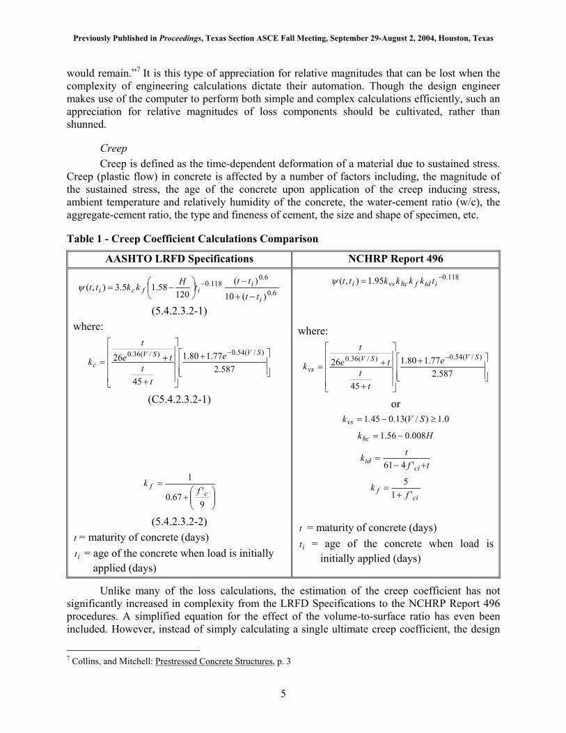
Table 1 - Creep Coefficient Calculations Comparison
AASHTO LRFD Specifications NCHRP Report 496
6.0
6.0118.0
)(10
)(120
58.15.3),(i
iifci
tt
tttHkktt
−+
−
−= −ψ
(5.4.2.3.2-1) where:
+
+
+=−
587.277.180.1
45
26 )/(54.0)/(36.0 SVSVc
e
tt
tet
k
(C5.4.2.3.2-1)
+
=
9'
67.0
1
cf f
k
(5.4.2.3.2-2) t = maturity of concrete (days) it = age of the concrete when load is initially
applied (days)
118.095.1),( −= itdfhcvsi tkkkkttψ
where:
+
+
+=−
587.277.180.1
45
26 )/(54.0)/(36.0 SVSVvs
e
tt
tet
k
or 0.1)/(13.045.1 ≥−= SVkvs
Hkhc 008.056.1 −=
tftk
citd +−
='461
cif f
k'1
5+
=
t = maturity of concrete (days) it = age of the concrete when load is
initially applied (days)
Unlike many of the loss calculations, the estimation of the creep coefficient has not significantly increased in complexity from the LRFD Specifications to the NCHRP Report 496 procedures. A simplified equation for the effect of the volume-to-surface ratio has even been included. However, instead of simply calculating a single ultimate creep coefficient, the design
7 Collins, and Mitchell: Prestressed Concrete Structures, p. 3
5
Previously Published in Proceedings, Texas Section ASCE Fall Meeting, September 29-August 2, 2004, Houston, Texas
engineer will need to calculate the coefficient for several different situations—at deck placement relative to transfer, at final relative to transfer, for final relative to deck placement, and for the deck. The creep coefficient calculation procedures are compared in . Table 1
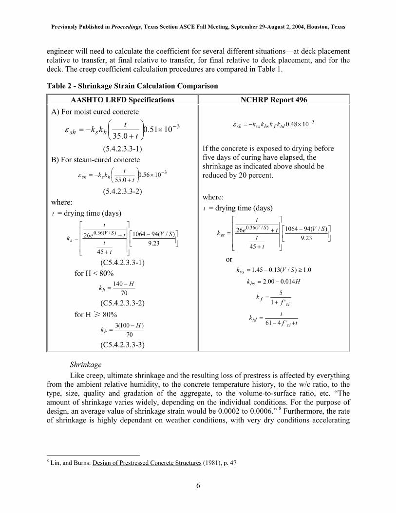
Table 2 - Shrinkage Strain Calculation Comparison
AASHTO LRFD Specifications NCHRP Report 496 A) For moist cured concrete
31051.00.35
−×
+−=
ttkk hsshε
(5.4.2.3.3-1) B) For steam-cured concrete
31056.00.55
−×
+−=
ttkk hsshε
(5.4.2.3.3-2) where: t = drying time (days)
−
+
+=23.9
)/(941064
45
26 )/(36.0 SV
tt
tet
kSV
s
(C5.4.2.3.3-1) for H < 80%
70
140 Hkh−
=
(C5.4.2.3.3-2) for H ≥ 80%
70)100(3 Hkh
−=
(C5.4.2.3.3-3)
31048.0 −×−= tdfhsvssh kkkkε
If the concrete is exposed to drying before five days of curing have elapsed, the shrinkage as indicated above should be reduced by 20 percent. where: t = drying time (days)
−
+
+=23.9
)/(941064
45
26 )/(36.0 SV
tt
tet
kSV
vs
or 0.1)/(13.045.1 ≥−= SVkvs
Hkhs 014.000.2 −=
cif f
k'1
5+
=
tftk
citd +−
='461
Shrinkage Like creep, ultimate shrinkage and the resulting loss of prestress is affected by everything
from the ambient relative humidity, to the concrete temperature history, to the w/c ratio, to the type, size, quality and gradation of the aggregate, to the volume-to-surface ratio, etc. “The amount of shrinkage varies widely, depending on the individual conditions. For the purpose of design, an average value of shrinkage strain would be 0.0002 to 0.0006.” 8 Furthermore, the rate of shrinkage is highly dependant on weather conditions, with very dry conditions accelerating
8 Lin, and Burns: Design of Prestressed Concrete Structures (1981), p. 47
6

Previously Published in Proceedings, Texas Section ASCE Fall Meeting, September 29-August 2, 2004, Houston, Texas
shrinkage such that ultimate shrinkage is achieved in a few months, and with wet conditions stooping or reversing shrinkage altogether.9
Similar to the creep coefficient calculations, the shrinkage strain formula has not significantly increased in complexity. However, there is the complication of considering the effects of the shrinkage of deck concrete, a consideration not made in the LRFD Specifications. Shrinkage strain calculation procedures are compared in . Table 2
Perspective on Creep and Shrinkage Losses Considering all the uncertainties inherent in the prediction of creep and shrinkage of
concrete and associated prestress losses, as discussed in this section, it is impossible for the design engineer to use creep and shrinkage formulae to predict the “actual” creep and shrinkage loss, since s/he has little or no control over the constituent make-up of the concrete, over the loading history of the prestressed concrete element being designed, and over the environment in which the prestressed concrete element is fabricated and “lives out” its service life. This fact should always remain in the mind of the design engineer.
Modulus of Elasticity The modulus of elasticity (MOE) of the concrete is a factor in the calculation of elastic
losses and gains as well as in the calculations of creep, shrinkage, and relaxation losses. Hence, its magnitude has wide ranging effects on prestress losses. Like creep and shrinkage, the prediction of MOE is wrought with uncertainty. The only change in the prediction of the MOE included in the NCHRP Report 496 revisions is the inclusion of a correction factor, K , which can be used to adjust the MOE to address differences due to aggregate source, available MOE test results, field experience, or other more accurate information when available. Similar multipliers were included in the NCHRP Report 496, as well as a multipliers to establish upper and lower bounds, for both creep and shrinkage. These have been removed for the implementation of the procedures in the 2005 Interim Specifications.
1
Table 3 - Modulus of Elasticity Calculation Comparison AASHTO LRFD Specifications NCHRP Report 496
ccc fwE '000,33 5.1=
(5.4.2.4-1) ccc fwKE '000,33 5.1
1=
Elastic Losses The elastic loss as it is in the current LRFD Specifications is a fairly simple calculation,
that only requires the engineer to make what is essentially an estimate of the elastic loss and then to check to see if the estimate was correct, or at least close enough. The equation remains unchanged in the NCHRP Report 496 procedures. However, verbiage is added to describe the special treatment of elastic losses when transformed section properties are used in the analysis. The authors believe that the intent of adding this verbiage is to warn the designer not to make the error of considering the elastic loss twice when transformed section properties are used. It also
9 Lin, and Burns: Design of Prestressed Concrete Structures (1981), p. 47-48
7
Previously Published in Proceedings, Texas Section ASCE Fall Meeting, September 29-August 2, 2004, Houston, Texas
seems to give credence to, or suggest that the engineer use, transformed section properties because of the ease with which the elastic losses can be determined (“no iteration required”). However, the previous method, which required the engineer to estimate the loss and then iterate until sufficient accuracy is achieved, probably requires less effort than determining the transformed section properties, thus reducing or eliminating any computational benefit that may have been realized. This is discussed in more detail in the following section.
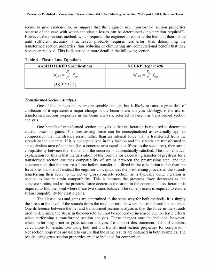
Table 4 - Elastic Loss Equations AASHTO LRFD Specifications NCHRP Report 496
cgpci
ppES f
EE
f =∆
(5.9.5.2.3a-1)
cgpci
ppES f
EE
f =∆
Transformed Section Analysis One of the changes that seems reasonable enough, but is likely to cause a great deal of
confusion as it represents a major change in the beam stress analysis ideology, is the use of transformed section properties in the beam analysis, referred to herein as transformed section analysis.
One benefit of transformed section analysis is that no iteration is required to determine elastic losses or gains. The prestressing force can be conceptualized as externally applied compression that the strands resist, rather than an internal force that is transferred from the strands to the concrete. If it is conceptualized in this fashion and the strands are transformed to an equivalent area of concrete (i.e. a concrete area equal in stiffness to the steel area), then strain compatibility between the strands and the concrete is automatically satisfied. The mathematical explanation for this is that the derivation of the formula for calculating transfer of prestress for a transformed section assumes compatibility of strains between the prestressing steel and the concrete such that the prestress force before transfer is utilized in the calculation rather than the force after transfer. If instead the engineer conceptualizes the prestressing process as the strands transferring their force to the net or gross concrete section, as is typically done, iteration is needed to ensure strain compatibility. This is because the prestress force decreases as the concrete strains, and as the prestress force decreases the strain in the concrete is less, iteration is required to find the point where these two strains balance. The same process is required to ensure strain compatibility for elastic gains.
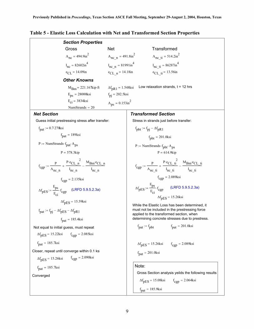
The elastic loss and gains are determined in the same way for both methods, it is simply the stress at the level of the strands times the modular ratio between the strands and the concrete. One difference between the net and transformed section analysis is that the force in the strands used to determine the stress in the concrete will not be reduced or increased due to elastic effects when performing a transformed section analysis. These changes must be included, however, when performing a net or gross section analysis. To support this statement, Table 5 contains calculations for elastic loss using both net and transformed section properties for comparison. Net section properties are used to ensure that the same results are obtained in both examples. The results using gross section properties are also included for comparison.
8
Previously Published in Proceedings, Texas Section ASCE Fall Meeting, September 29-August 2, 2004, Houston, Texas
Table 5 - Elastic Loss Calculation with Net and Transformed Section Properties
NumStrands 20=Aps 0.153in2
=Eci 3834ksi=
fpj 202.5ksi=Eps 28000ksi=
Low relaxation strands, t = 12 hrs∆fpR1 1.548ksi=MBm 221.167kip ft⋅=
Other Knowns
eCL_ti 13.56in=eCL_n 14.18in=eCL 14.09in=
Inc_ti 86287in4=Inc_n 81991in4
=Inc 82602in4=
Anc_ti 514.2in2=Anc_n 491.8in2
=Anc 494.9in2=
Transformed Net Gross Section Properties
Net Section
Guess initial prestressing stress after transfer:
fpat 0.7 270⋅ ksi:=
fpat 189ksi=
P NumStrands fpat⋅ Aps⋅:=
P 578.3kip=
fcgpP
Anc_n
P eCL_n2
⋅
Inc_n+
MBm eCL_n⋅
Inc_n−:=
fcgp 2.135ksi=
∆fpESEpsEci
fcgp⋅:= (LRFD 5.9.5.2.3a)
∆fpES 15.59ksi=
fpat fpj ∆fpES− ∆fpR1−:=
fpat 185.4ksi=
Not equal to initial guess, must repeat ∆fpES 15.22ksi= fcgp 2.085ksi=
fpat 185.7ksi=
Closer, repeat until converge within 0.1 ksi fcgp 2.090ksi=∆fpES 15.26ksi=
fpat 185.7ksi=
Converged
fpat 201.0ksi=
fcgp 2.089ksi=∆fpES 15.26ksi=
fpat 201.0ksi=fpat fpbt:=
While the Elastic Loss has been determined, it must not be included in the prestressing forceapplied to the transformed section, when determining concrete stresses due to prestress.
∆fpES 15.26ksi=
(LRFD 5.9.5.2.3a)∆fpESEpsEci
fcgp⋅:=
fcgp 2.089ksi=
fcgpP
Anc_ti
P eCL_ti2
⋅
Inc_ti+
MBm eCL_ti⋅
Inc_ti−:=
P 614.9kip=
P NumStrands fpbt⋅ Aps⋅:=
fpbt 201.0ksi=
fpbt fpj ∆fpR1−:=
Stress in strands just before transfer:
Transformed Section
Note: Gross Section analysis yeilds the following results
∆fpES 15.08ksi= fcgp 2.064ksi=
fpat 185.9ksi=
9
Previously Published in Proceedings, Texas Section ASCE Fall Meeting, September 29-August 2, 2004, Houston, Texas
Elastic Gains The NCHRP Report 496 method allows for the direct inclusion of elastic gains due to
superimposed dead loads and live loads. Accounting for the elastic gains allows the engineer to rely on considerably reduced losses, which could reduce the number of strands required for a given beam. These gains have conservatively been neglected in the past and the wording of the revised specifications will allow engineers to continue this practice should they so choose.
The inclusion of elastic gains also requires that at each intermediate stage of loading or stress check only realized elastic gains may be considered. In other words, the engineer must exercise due diligence to insure that only the gains resulting from loads applied at the stage considered be relied upon. Thus, each load case considered will have its unique associated prestress force. This is a significant departure from current practice.
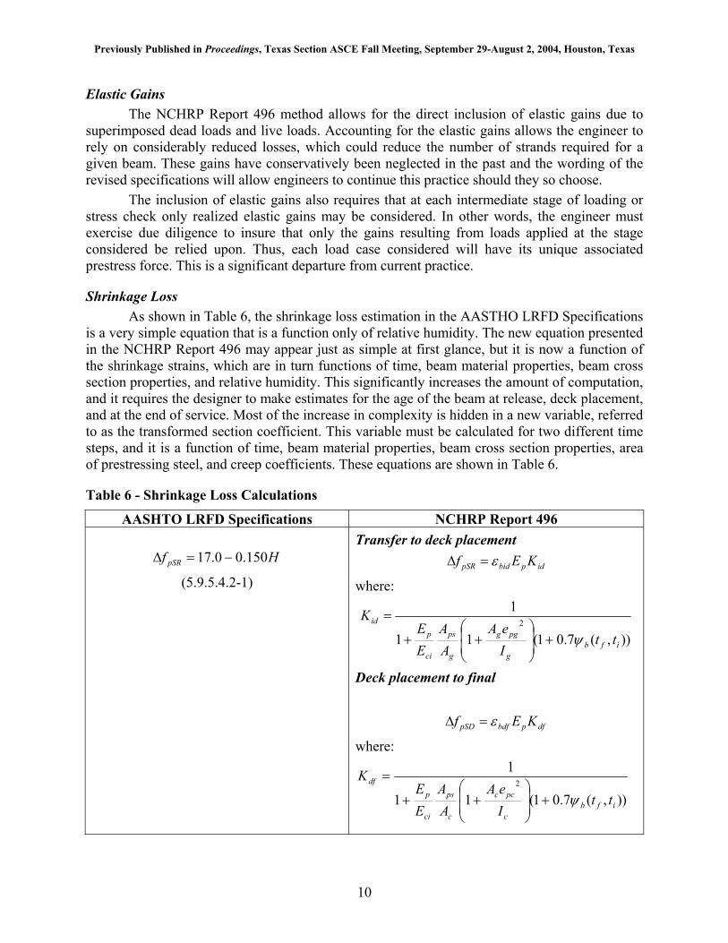
Shrinkage Loss As shown in Table 6, the shrinkage loss estimation in the AASTHO LRFD Specifications
is a very simple equation that is a function only of relative humidity. The new equation presented in the NCHRP Report 496 may appear just as simple at first glance, but it is now a function of the shrinkage strains, which are in turn functions of time, beam material properties, beam cross section properties, and relative humidity. This significantly increases the amount of computation, and it requires the designer to make estimates for the age of the beam at release, deck placement, and at the end of service. Most of the increase in complexity is hidden in a new variable, referred to as the transformed section coefficient. This variable must be calculated for two different time steps, and it is a function of time, beam material properties, beam cross section properties, area of prestressing steel, and creep coefficients. These equations are shown in Table 6.
Table 6 - Shrinkage Loss Calculations
AASHTO LRFD Specifications NCHRP Report 496
Hf pSR 150.00.17 −=∆
(5.9.5.4.2-1)
Transfer to deck placement
idpbidpSR KEf ε=∆
where:
)),(7.01(11
12
ifbg
pgg
g
ps
ci
pid
ttIeA
AA
EE
K
ψ+
++
=
Deck placement to final
where:
)),(7.01(11
12
ifbc
pcc
c
ps
ci
ttIeA
AA
EE
K
ψ+
++
=
dfpbdfpSD KEf ε=∆
10
Previously Published in Proceedings, Texas Section ASCE Fall Meeting, September 29-August 2, 2004, Houston, Texas
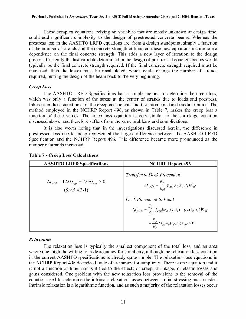
These complex equations, relying on variables that are mostly unknown at design time, could add significant complexity to the design of prestressed concrete beams. Whereas the prestress loss in the AASHTO LRFD equations are, from a design standpoint, simply a function of the number of strands and the concrete strength at transfer, these new equations incorporate a dependence on the final concrete strength. This adds a new layer of iteration to the design process. Currently the last variable determined in the design of prestressed concrete beams would typically be the final concrete strength required. If the final concrete strength required must be increased, then the losses must be recalculated, which could change the number of strands required, putting the design of the beam back to the very beginning.
Creep Loss The AASHTO LRFD Specifications had a simple method to determine the creep loss,
which was only a function of the stress at the center of strands due to loads and prestress. Inherent in these equations are the creep coefficients and the initial and final modular ratios. The method employed in the NCHRP Report 496, as shown in Table 7, makes the creep loss a function of these values. The creep loss equation is very similar to the shrinkage equation discussed above, and therefore suffers from the same problems and complications.
It is also worth noting that in the investigations discussed herein, the difference in prestressed loss due to creep represented the largest difference between the AASHTO LRFD Specification and the NCHRP Report 496. This difference became more pronounced as the number of strands increased.
Table 7 - Creep Loss Calculations
AASHTO LRFD Specifications NCHRP Report 496
00.70.12 ≥∆−=∆ cdpcgppCR fff
(5.9.5.4.3-1)
Transfer to Deck Placement
ididbcgpci
ppCR Kttf
E
Ef ),(ψ=∆
Deck Placement to Final
( ) dfidbifbcgpci
ppCD Kttttf
E
Ef ),(),( ψψ −=∆
0),( ≥∆ dfdfbcdc
p Kttf ψ+EE
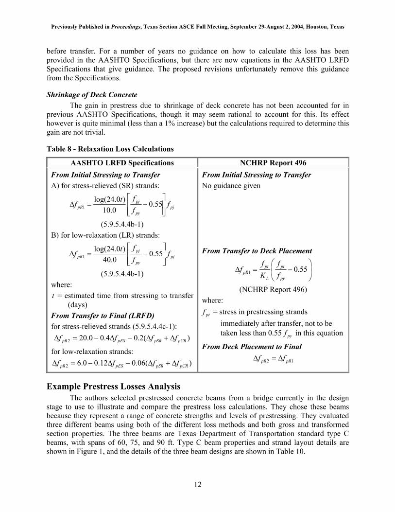
Relaxation The relaxation loss is typically the smallest component of the total loss, and an area
where one might be willing to trade accuracy for simplicity, although the relaxation loss equation in the current AASHTO specifications is already quite simple. The relaxation loss equations in the NCHRP Report 496 do indeed trade off accuracy for simplicity. There is one equation and it is not a function of time, nor is it tied to the effects of creep, shrinkage, or elastic losses and gains considered. One problem with the new relaxation loss provisions is the removal of the equation used to determine the intrinsic relaxation losses between initial stressing and transfer. Intrinsic relaxation is a logarithmic function, and as such a majority of the relaxation losses occur
11
Previously Published in Proceedings, Texas Section ASCE Fall Meeting, September 29-August 2, 2004, Houston, Texas
before transfer. For a number of years no guidance on how to calculate this loss has been provided in the AASHTO Specifications, but there are now equations in the AASHTO LRFD Specifications that give guidance. The proposed revisions unfortunately remove this guidance from the Specifications.
Shrinkage of Deck Concrete The gain in prestress due to shrinkage of deck concrete has not been accounted for in
previous AASHTO Specifications, though it may seem rational to account for this. Its effect however is quite minimal (less than a 1% increase) but the calculations required to determine this gain are not trivial.
Table 8 - Relaxation Loss Calculations
AASHTO LRFD Specifications NCHRP Report 496 From Initial Stressing to Transfer A) for stress-relieved (SR) strands:
pjpy
pjpR f
fftf
−=∆ 55.0
0.10)0.24log(
1
(5.9.5.4.4b-1) B) for low-relaxation (LR) strands:
pjpy
pjpR f
fftf
−=∆ 55.0
0.40)0.24log(
1
(5.9.5.4.4b-1) where: t = estimated time from stressing to transfer
(days) From Transfer to Final (LRFD) for stress-relieved strands (5.9.5.4.4c-1):
)(2.04.00.202 pCRpSRpESpR ffff ∆+∆−∆−=∆
for low-relaxation strands: )(06.012.00.62 pCRpSRpESpR ffff ∆+∆−∆−=∆
From Initial Stressing to Transfer No guidance given From Transfer to Deck Placement
−=∆ 55.01
py
pt
L
ptpR f
fKf
f
(NCHRP Report 496) where:
ptf = stress in prestressing strands immediately after transfer, not to be taken less than 0.55 in this equation pyf
From Deck Placement to Final
12 pRpR ff ∆=∆
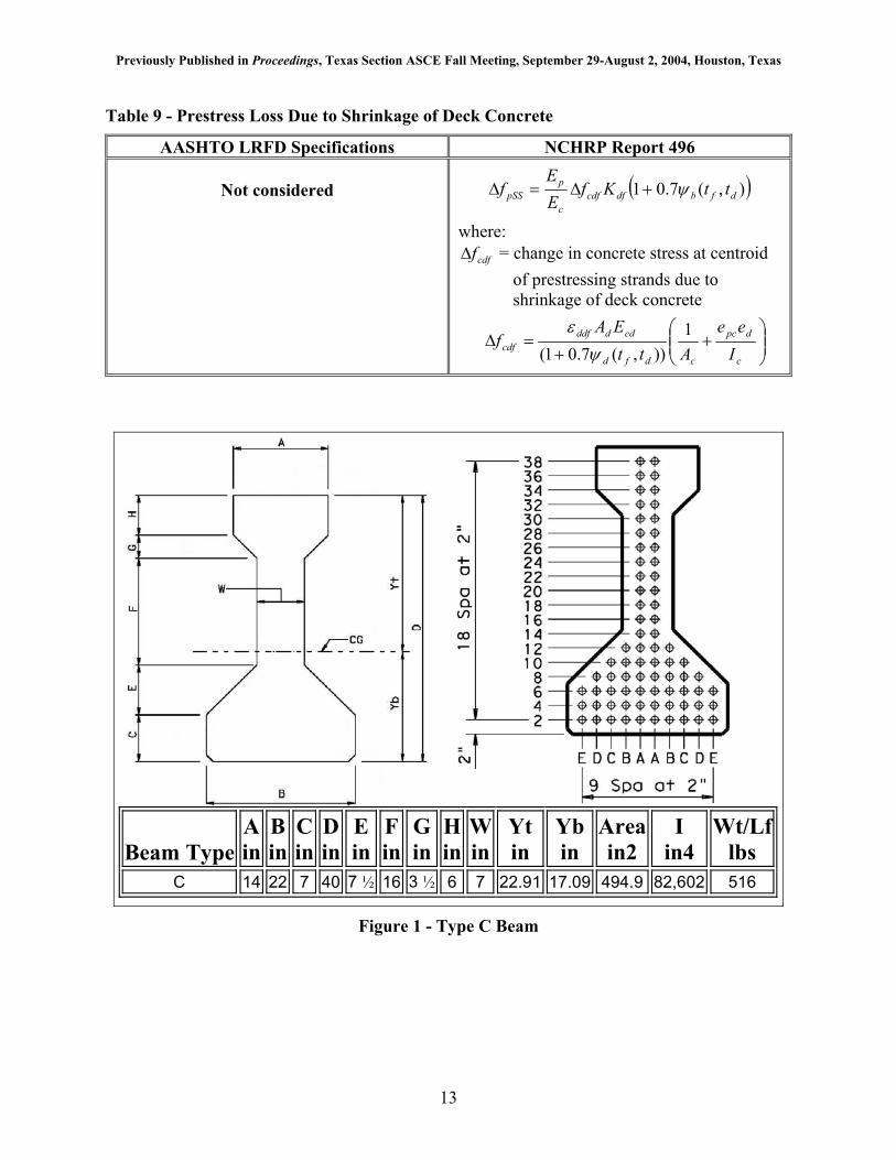
Example Prestress Losses Analysis The authors selected prestressed concrete beams from a bridge currently in the design
stage to use to illustrate and compare the prestress loss calculations. They chose these beams because they represent a range of concrete strengths and levels of prestressing. They evaluated three different beams using both of the different loss methods and both gross and transformed section properties. The three beams are Texas Department of Transportation standard type C beams, with spans of 60, 75, and 90 ft. Type C beam properties and strand layout details are shown in Figure 1, and the details of the three beam designs are shown in Table 10.
12
Previously Published in Proceedings, Texas Section ASCE Fall Meeting, September 29-August 2, 2004, Houston, Texas
Table 9 - Prestress Loss Due to Shrinkage of Deck Concrete
AASHTO LRFD Specifications NCHRP Report 496
Not considered ( )),(7.01 dfbdfcdfc
ppSS ttKf
EE
f ψ+∆=∆
where: cdff∆ = change in concrete stress at centroid
of prestressing strands due to shrinkage of deck concrete
+
+=∆
c
dpc
cdfd
cddddfcdf I
eeAtt
EAf 1
)),(7.01( ψε
Beam Type A in
B in
C in
D in
Ein
Fin
Gin
Hin
Win
Yt in
Ybin
Area in2
I in4
Wt/Lflbs
C 14 22 7 40 7 ½ 16 3 ½ 6 7 22.91 17.09 494.9 82,602 516
Figure 1 - Type C Beam
13
Previously Published in Proceedings, Texas Section ASCE Fall Meeting, September 29-August 2, 2004, Houston, Texas
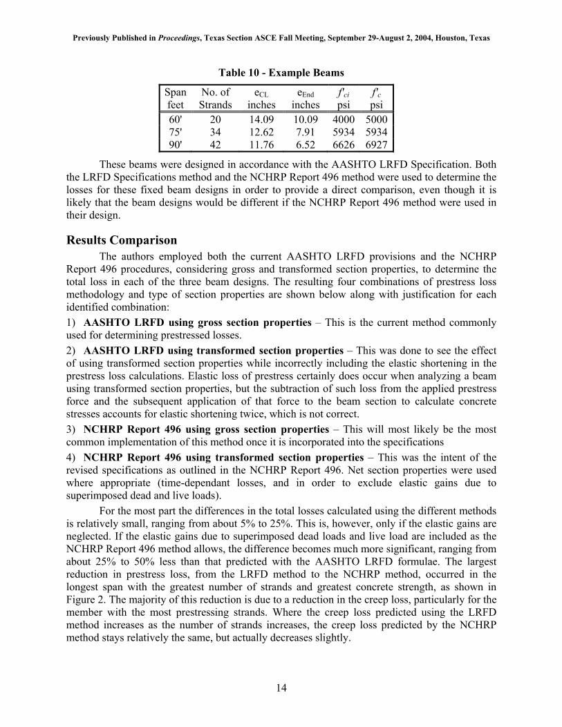
Table 10 - Example Beams
Span feet
No. of Strands
eCL inches
eEnd inches
f'ci psi
f'c psi
60' 20 14.09 10.09 4000 500075' 34 12.62 7.91 5934 593490' 42 11.76 6.52 6626 6927
These beams were designed in accordance with the AASHTO LRFD Specification. Both the LRFD Specifications method and the NCHRP Report 496 method were used to determine the losses for these fixed beam designs in order to provide a direct comparison, even though it is likely that the beam designs would be different if the NCHRP Report 496 method were used in their design.
Results Comparison The authors employed both the current AASHTO LRFD provisions and the NCHRP
Report 496 procedures, considering gross and transformed section properties, to determine the total loss in each of the three beam designs. The resulting four combinations of prestress loss methodology and type of section properties are shown below along with justification for each identified combination: 1) AASHTO LRFD using gross section properties – This is the current method commonly used for determining prestressed losses. 2) AASHTO LRFD using transformed section properties – This was done to see the effect of using transformed section properties while incorrectly including the elastic shortening in the prestress loss calculations. Elastic loss of prestress certainly does occur when analyzing a beam using transformed section properties, but the subtraction of such loss from the applied prestress force and the subsequent application of that force to the beam section to calculate concrete stresses accounts for elastic shortening twice, which is not correct. 3) NCHRP Report 496 using gross section properties – This will most likely be the most common implementation of this method once it is incorporated into the specifications 4) NCHRP Report 496 using transformed section properties – This was the intent of the revised specifications as outlined in the NCHRP Report 496. Net section properties were used where appropriate (time-dependant losses, and in order to exclude elastic gains due to superimposed dead and live loads).
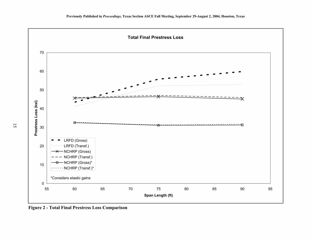
For the most part the differences in the total losses calculated using the different methods is relatively small, ranging from about 5% to 25%. This is, however, only if the elastic gains are neglected. If the elastic gains due to superimposed dead loads and live load are included as the NCHRP Report 496 method allows, the difference becomes much more significant, ranging from about 25% to 50% less than that predicted with the AASHTO LRFD formulae. The largest reduction in prestress loss, from the LRFD method to the NCHRP method, occurred in the longest span with the greatest number of strands and greatest concrete strength, as shown in
. The majority of this reduction is due to a reduction in the creep loss, particularly for the member with the most prestressing strands. Where the creep loss predicted using the LRFD method increases as the number of strands increases, the creep loss predicted by the NCHRP method stays relatively the same, but actually decreases slightly.
Figure 2
14
Previously Published in Proceeding
0
10
20
30
40
50
60
70
55 60 65
Pres
tres
s Lo
ss (k
si)
LRFD (Gross)LRFD (Transf.)NCHRP (Gross)NCHRP (Transf.)NCHRP (Gross)*NCHRP (Transf.)*
*Considers elastic gains
15
Figure 2 - Total Final Prestress Loss Compar
s, Texas Section ASCE Fall Meeting, September 29-August 2, 2004, Houston, Texas
Total Final Prestress Loss
70 75 80 85 90 95
Span Length (ft)
ison
Previously Published in Proceeding
Final Bottom Fiber S
-1
-0.9
-0.8
-0.7
-0.6
-0.5
-0.4
-0.3
-0.2
-0.1
055 60 65
Stre
ss (k
si)
LRFD (Gross)LRFD (Transf.)NCHRP (Gross)NCHRP (Net/Transf.)NCHRP (Gross)*NCHRP (Net/Transf.)*
*Considers elastic gains
16
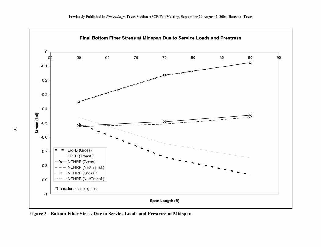
Figure 3 - Bottom Fiber Stress Due to Service
s, Texas Section ASCE Fall Meeting, September 29-August 2, 2004, Houston, Texas
tress at Midspan Due to Service Loads and Prestress
70 75 80 85 90 95
Span Length (ft)
Loads and Prestress at Midspan
Previously Published in Proceedings, Texas Section ASCE Fall Meeting, September 29-August 2, 2004, Houston, Texas
The losses estimated using the LRFD method increased as the number of strands and concrete strength increased, while the NCHRP loss calculations estimated approximately the same loss for all three beams. Figure 2 also shows that when used correctly, transformed section analysis and gross section analysis produce essentially the same prestress loss.
Any increase in prestressing force, by either increased number of strands or a reduction in losses, results in reduced bottom fiber tension. Figure 3 shows the bottom fiber tension at midspan due to full service loads (including 100% of the HL-93 load). This tension, that often controls the number of strands, is reduced by up to 50% when using the NCHRP method losses. An even greater reduction, up to 90%, is seen when the elastic gains are included. These reductions in loss, when used in design, could substantially reduce the number of strands required, especially when the elastic gains are included. The pattern that appears using the somewhat limited investigation of three beams is that longer beams will have fewer strands and shorter beams will require more using the new loss estimation procedures. This figure also shows that the difference between a gross section analysis and its corresponding transformed or net section analysis are in fact negligible, when the elastic deformations effect on the loss is handled properly. The line representing the LRFD Specifications results using transformed section properties shows the effect of improperly accounting for elastic shortening when using transformed sections.
CONCLUSIONS AND RECOMMENDATIONS Since these new loss provisions have been approved by the AASHTO SCOBS for
incorporation in the 2005 Interims to the AASHTO LRFD Specifications, a recommendation on whether or not this new loss method should be used would be irrelevant. However, recommendations which guide the design engineer in the application of the new prestress losses procedures are useful; the following recommendations are therefore offered: • Continued neglect of elastic gains: It is not recommended that the design engineer take advantage of the elastic gains due to superimposed dead and live loads. This creates a substantial reduction in the loss compared to equations that have been used for many years without problems. Further research should be done, using beams designed with these new loss calculations before engineers should routinely take advantage of this in their loss calculations. • Continued use of gross section properties: The use of transformed section properties in the analysis is not recommended, due to its increased complexity and the confusion that is inherent with the nuances of its use. Any small benefit that may be obtained by the increased accuracy is easily offset by the potential for mistakes and the lack of understanding that is likely to result. Additionally, the use of transformed sections in the analysis typically precludes the ability to neglect the elastic gains as recommended above. • Implementation using known material properties: If more specific information about the concrete material properties is available during the design stage, the prestressed loss method as outlined in the NCHRP Report 496, including the adjustment factors for properties such as creep, shrinkage, and modulus of elasticity, may be used. The loss prediction method as outlined in the report provides a good framework for taking advantage of this information when available. However, the recommendations above would still stand.
Though it is admirable that the researchers and authors of NCHRP Report 496 are pursuing more accurate loss calculation procedures that may, if enough information is available at design time, allow bridge design engineers to create more efficient designs, such “accuracy” is
17
Previously Published in Proceedings, Texas Section ASCE Fall Meeting, September 29-August 2, 2004, Houston, Texas
not something that lends itself to routine bridge design. There are a large number of variables that are unknown at design time, but that nevertheless have a substantial effect on the prestress losses. The modulus of elasticity of the concrete, the curing conditions, and the actual concrete strength are typically not known with any level of accuracy when the losses are calculated. The fact that these variables are not currently well known at design time should not preclude efforts to obtain a better understanding of these variables, such as the concrete modulus of elasticity and creep properties, which have such a significant effect on the behavior and design of prestressed concrete structural members. Design engineers and design specifications writers may be well served to recognize that the precision that is indicated in the complexity of the prestress loss calculations should be kept in line with the degree of knowledge of the material properties which the calculations are dependant upon.
REFERENCES American Association of State Highway and Transportation Officials, “AASHTO-LRFD Bridge Design Specifications,” Third Edition, Washington, DC (2004)
Collins, M. P. and Mitchell, D., Prestressed Concrete Structures, Response Publications, Canada (1997), 765 pp.
Kelly, D.J., Bradberry, T. E., and Breen, J. E., “Time-Dependent Deflections of Pretensioned Beams.” Research Report 381-1, Research Project 3-5-84-381, Center for Transportation Research, Bureau of Engineering Research, The University of Texas at Austin, Austin, TX (August 1987) 211 pp.
Lin, T.Y. and Burns, N.H., Design of Prestressed Concrete Structures, John Wiley and Sons, 3rd Edition (1981), 646 pp.
Myers, J. J., and Carrasquillo, R. L., “Production and Quality Control of High Performance Concrete in Texas Bridge Structures.” Research Report 580/589-1, Center for Transportation Research, University of Texas, Austin, TX (1999) 176 pp.
Tadros, M. K., Al-Omaishi, N., Seguirant, S. J., and Gallt, J. G. Prestress Losses in Pretensioned High-Strength Concrete Bridge Girders. NCHRP Report 496, Transportation Research Board, Washington, DC, (2003) 63 pp.
APPENDIX—NOTATION cA = net area of the composite section with the slab transformed to beam
concrete using the slab-to-beam modular ratio
dA = area of deck concrete
gA = gross area of the beam
cdE = modulus of elasticity of deck concrete
ciE = modulus of elasticity of concrete at transfer (ksi)
ctE = modulus of elasticity of concrete at transfer or time of load application (ksi)
pE = modulus of elasticity of prestressing steel (ksi)
18
Previously Published in Proceedings, Texas Section ASCE Fall Meeting, September 29-August 2, 2004, Houston, Texas
de = eccentricity of deck with respect to the net composite section with transformed deck, taken negative in common construction
pce = eccentricity of strands with respect to centroid of composite section
pge = eccentricity of strands with respect to centroid of girder
cf ' = compressive strength of concrete at 28 days
cgpf (LRFD) = sum of concrete stresses at the center of gravity of prestressing tendons due to the prestressing force at transfer and the self-weight of the member at the sections of maximum moment (ksi)
cgpf (NCHRP) = sum of concrete stresses at the center of gravity of prestressing tendons due to the prestressing force immediately after transfer and the self-weight of the member at the sections of maximum moment (ksi). Also, change of concrete stress at the center of gravity of prestressing tendons due to subsequent applied loads, when considered.
cif ' = compressive strength of concrete at time of prestressing
pjf = initial stress in the tendon at the end of stressing (ksi)
pyf = specified yield strength of prestressing steel (ksi)
H = relative humidity (%)
cI = moment of inertia of net composite section with the slab transformed to beam concrete using the slab-to-beam modular ratio
1K = correction factor for source aggregate to be taken as 1.0 unless determined by physical test, and as approved by authority of jurisdiction
dfK = transformed section coefficient that accounts for time-dependent interaction between concrete and bonded steel in the section being considered for the time period between deck placement and final time
idK = transformed section coefficient that accounts for time-dependent interaction between concrete and bonded steel in the section being considered for the time period between transfer and deck placement
LK = factor for strand type, 30 for low-relaxation strands and 7 for other prestressing steel, unless more accurate manufacturer’s data are available
ck = factor for the effect of the volume-to-surface ratio
fk = factor for the effect of concrete strength
hk = humidity factor
hck = humidity factor for creep
hsk = humidity factor for shrinkage
sk = size factor
19
Previously Published in Proceedings, Texas Section ASCE Fall Meeting, September 29-August 2, 2004, Houston, Texas
tdk = time development factor
vsk = factor for the effect of the volume-to-surface ratio of the component
dt = age at deck placement (days)
ft = final age (days)
SV / = volume-to-surface-ratio
cw = unit weight of concrete (kip/ft3)
cdf∆ = change in concrete stress at centroid of prestressing strands due to long-term losses between transfer and deck placement, combined with deck weight and superimposed loads
cdff∆ = change in concrete stress at centroid of prestressing strands due to shrinkage of deck concrete
pSRf∆ = prestress loss due to shrinkage of girder concrete between transfer and deck placement
pCDf∆ = prestress loss due to creep of girder concrete between time of deck placement and final time
pCRf∆ = prestress loss due to creep of girder concrete between transfer and deck placement
pESf∆ (LRFD) = loss due to elastic shortening
pESf∆ (NCHRP) = sum of all losses and gains due to elastic deformations caused by applied loads and prestress
pLTf∆ = prestress loss due to long-term shrinkage and creep of concrete, and relaxation of prestressing steel
1pRf∆ (LRFD) = prestress loss due to relaxation of prestressing strands between initial stressing of the strands and transfer
1pRf∆ (NCHRP) = prestress loss due to relaxation of prestressing strands between time of transfer and deck placement
2pRf∆ (LRFD) = prestress loss due to relaxation of prestressing strands from transfer to final time
2pRf∆ (NCHRP) = prestress loss due to relaxation of prestressing strands in composite section between time of deck placement and final time
pSDf∆ = prestress loss due to shrinkage between deck placement and final time
pSRf∆ = prestress loss due to shrinkage between transfer and deck placement
pSSf∆ = prestress loss due to shrinkage of composite deck
pTf∆ = total prestress loss
20

Previously Published in Proceedings, Texas Section ASCE Fall Meeting, September 29-August 2, 2004, Houston, Texas
21
bdfε = concrete shrinkage strain of girder between time of deck placement and final time
bidε = concrete shrinkage strain of girder between time of transfer and deck placement
ddfε = shrinkage strain of deck concrete between placement and final time
),( idb ttψ = girder creep coefficient at the time of deck placement due to loading introduced at transfer
),( dfb ttψ = girder creep coefficient at final time due to loading introduced at deck placement
),( ifb ttψ = girder creep coefficient at final time due to loading introduced at transfer