Embed Size (px)
Citation preview

EE 435
Lecture 26
Data ConvertersData Converter Characterization

Data Converter ArchitecturesINX
• Large number of different circuits have been proposed for building data converters
• Often a dramatic difference in performance from one structure to another
• Performance of almost all structures are identical if ideal components are used
• Much of data converter design involves identifying the problems associated with a given structure and figuring out ways to reduce the effects of these problems
• Critical that all problems that are significant be identified and solved
• Many of the problems are statistical in nature and implications of not solving problems are in a yield loss that may be dramatic
.••
••
•R
evie
w fr
om la
st le
ctur
e .•
••
••
Data Converter ArchitecturesINX
Nyquist RateFlashPipelineTwo-step and Multi-StepInterpolatingAlgorithmic/CyclicSuccessive Approximation RegisterSingle Slope / Dual SlopeSubrangingFolded
Current SteeringR-stringCharge RedistributionAlgorithmicR-2R (ladder)PipelinedSubranging
Over-Sampled (Delta-Sigma)Discrete-timeFirst-order/Higher OrderContinuous-time
Discrete-timeFirst-order/Higher OrderContinuous-time
.••
••
•R
evie
w fr
om la
st le
ctur
e .•
••
••

Performance Characterization of Data Converters
• A very large number of parameters (2n) characterize the static performance of an ADC!
• A large (but much smaller) number of parameters are invariably used to characterize a data converter
• Performance parameters of interest depend strongly on the application
• Very small number of parameters of interest in many/most applications
• “Catalog” data converters are generally intended to satisfy a wide rangeof applications and thus have much more stringent requirements placd on their performance
• Custom application-specific data converter will generally perform much better than a “catalog” part in the same
INX

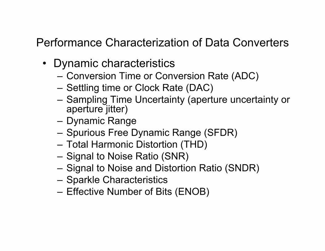
Performance Characterization of Data Converters
• Static characteristics– Resolution– Least Significant Bit (LSB)– Offset and Gain Errors– Absolute Accuracy– Relative Accuracy– Integral Nonlinearity (INL)– Differential Nonlinearity (DNL)– Monotonicity (DAC)– Missing Codes (ADC)– Low-f Spurious Free Dynamic Range (SFDR)– Low-f Total Harmonic Distortion (THD)– Effective Number of Bits (ENOB)– Power Dissipation
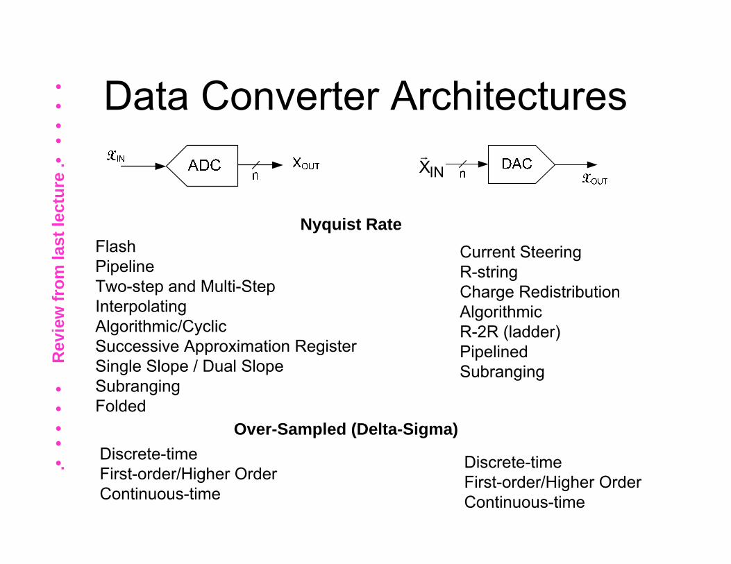
Performance Characterization of Data Converters
• Dynamic characteristics– Conversion Time or Conversion Rate (ADC)– Settling time or Clock Rate (DAC)– Sampling Time Uncertainty (aperture uncertainty or
aperture jitter)– Dynamic Range– Spurious Free Dynamic Range (SFDR)– Total Harmonic Distortion (THD)– Signal to Noise Ratio (SNR)– Signal to Noise and Distortion Ratio (SNDR)– Sparkle Characteristics– Effective Number of Bits (ENOB)

Dynamic characteristics
• Degradation of dynamic performance parameters often due to nonideal effects in time-domain performance
• Dynamic characteristics often high resolution data converters often challenging to measure, to simulate, to understand source of contributions, and to minimize
Example: An n-bit ADC would often require SFDR at the 6n+6 bit level or better. Thus, considering a 14-bit ADC, the SFDR would be expected to be at the -90dB level or better.If the input to the ADC is a 1V p-p sinusoidal waveform, the second harmonic term would need to be at the level. A 32uV level is about 1part in 30,000. Signals at this level are difficult to accurately simulate in the presence of a 1V level signal. For example, convergence parameters in simulators and sample (strobe) points used in data acquisition adversely affect simulation results and observing the time domain waveforms that contribute to nonlinearity at this level and relationships between these waveforms and the sources of nonlinearity is often difficult to visualize. Simulation errors that are at the 20dB level or worse can occur if the simulation environment is not correctly established.
( )90 / 2010 32μVdB dB− =

Performance Characterization of Data Converters
What is meant by “low frequency” ?
Operation at frequencies so low that further decreases in frequency cause no further changes in a parameter of interest
Low frequency operation is often termed Pseudo-static operation

Low-frequency or Pseudo-Static Performance
Performance Characterization of Data Converters
• Static characteristics– Resolution– Least Significant Bit (LSB)– Offset and Gain Errors– Absolute Accuracy– Relative Accuracy– Integral Nonlinearity (INL)– Differential Nonlinearity (DNL)– Monotonicity (DAC)– Missing Codes (ADC)– Low-f Spurious Free Dynamic Range (SFDR)– Low-f Total Harmonic Distortion (THD)– Effective Number of Bits (ENOB)– Power Dissipation

Performance Characterization
• Number of distinct analog levels in an ADC• Number of digital output codes in A/D• In most cases this is a power of 2• If a converter can resolve 2n levels, then we term it an n-bit
converter– 2n analog outputs for an n-bit DAC– 2n-1 transition points for an n-bit ADC
• Resolution is often determined by architecture and thus not measured
• Effective resolution can be defined and measured– If N levels can be resolved for an DAC then
– If N-1 transition points in an ADC, then
Resolution
EQlogNn =log2
EQlogNn =log2
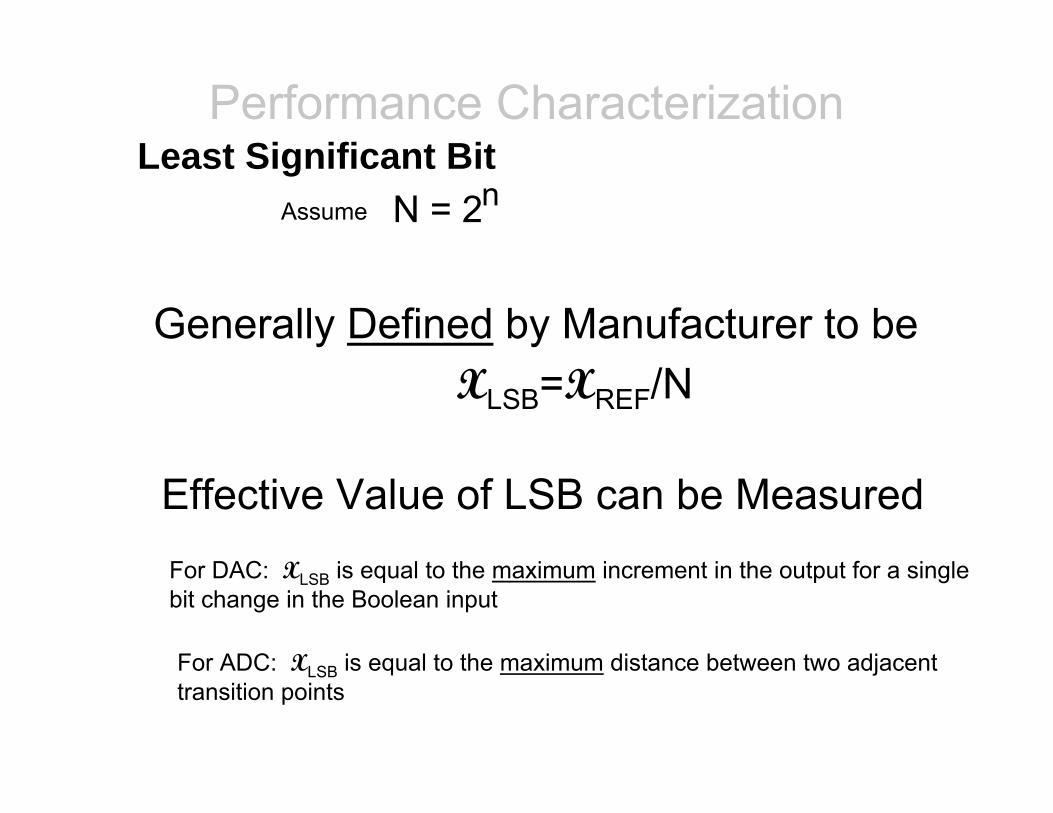
Performance Characterization
Generally Defined by Manufacturer to beXLSB=XREF/N
Least Significant BitAssume nN = 2
Effective Value of LSB can be MeasuredFor DAC: XLSB is equal to the maximum increment in the output for a single bit change in the Boolean input
For ADC: XLSB is equal to the maximum distance between two adjacent transition points

Performance Characterization
XOUT (<0,…, 0>) - absolute
- in LSB
OffsetFor DAC the offset is
( )OUT
LSB
0,...,0
X
XXOUT
INXC0 C1 C2 C3 C4 C5 C6 C7
XREF
Offset
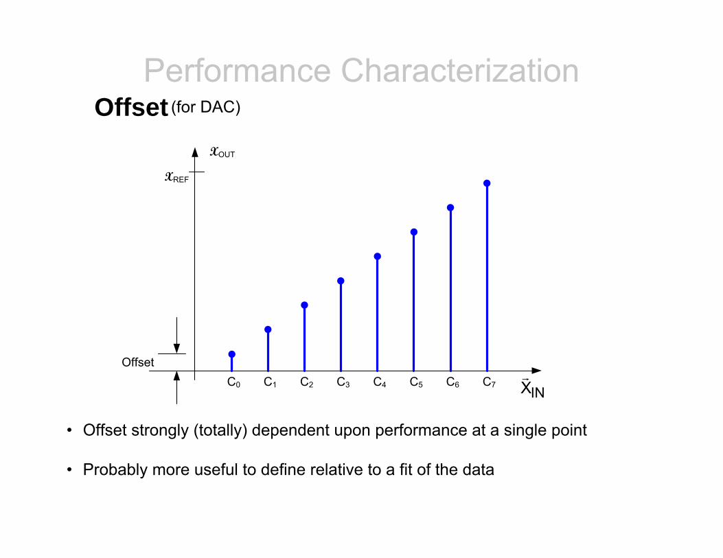
Performance CharacterizationOffset
XOUT
INXC0 C1 C2 C3 C4 C5 C6 C7
XREF
Offset
• Offset strongly (totally) dependent upon performance at a single point
• Probably more useful to define relative to a fit of the data
(for DAC)

Performance CharacterizationOffset
Offset relative to fit of data
INX
(for DAC)

Performance Characterization
XT1 -XLSB - absolute
- in LSB
OffsetFor ADC the offset is
T1 LSBLSB −X X
XOUTX
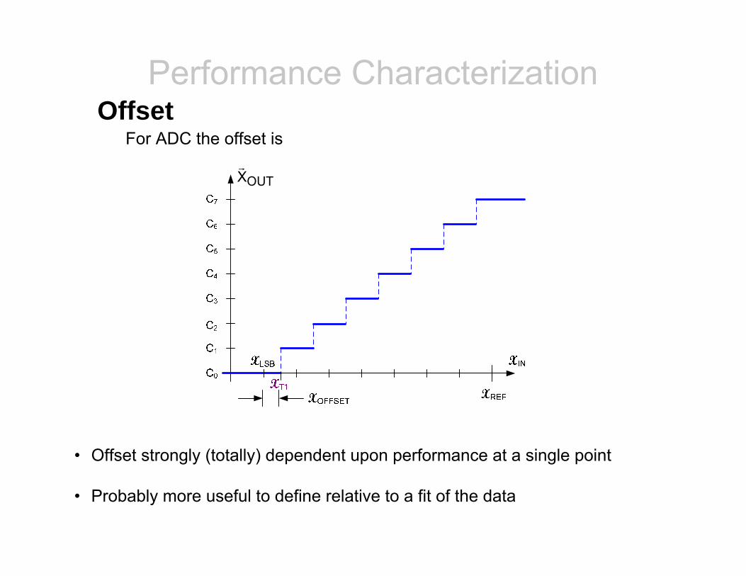
Performance CharacterizationOffset
For ADC the offset is
OUTX
• Offset strongly (totally) dependent upon performance at a single point
• Probably more useful to define relative to a fit of the data

Performance CharacterizationOffset
For ADC the offset is
OUTX
Offset relative to fit of data

Performance CharacterizationGain and Gain Error
XOUT
INXC0 C1 C2 C3 C4 C5 C6 C7
XREF Gain Error
Ideal Output
Actual Output
For DAC
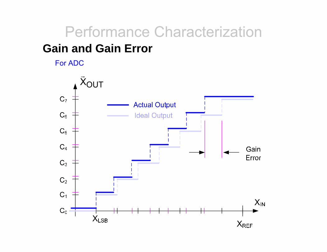
Performance CharacterizationGain and Gain Error
OUTX
For ADC

Performance Characterization
Gain and Offset Errors
• Fit line would give better indicator of error in gain but less practical to obtain in test
• Gain and Offset errors of little concern in many applications
• Performance often nearly independent of gain and offset errors
• Can be trimmed in field if gain or offset errors exist.

Integral Nonlinearity (DAC)
INX
Nonideal DAC

Integral Nonlinearity (DAC)Nonideal DAC
INX
OF(k)X
( ) ( ) ( )( )OF OUT OUTk = mk+ N-1 - 0X X X
( ) ( ) OUT OUTN-1 - 0m=
N-1X X

Integral Nonlinearity (DAC)Nonideal DAC
INX
( ) ( )k OUT OFINL = k - kX X
{ }k0 k N-1
INL= max INL≤ ≤

Integral Nonlinearity (DAC)Nonideal DAC
INXC0 C1 C2 C3 C4 C5 C6 C7
XREF
XOUT

Integral Nonlinearity (DAC)Nonideal DAC
INXC0 C1 C2 C3 C4 C5 C6 C7
XREF
INL
XOUT
INL often expressed in LSB
( ) ( ) OUT OFk
LSB
k - kINL =
X XX
{ }k0 k N-1
INL= max INL≤ ≤
• INL is often the most important parameter of a DAC• INL0 and INLN-1 are 0 (by definition)• There are N-2 elements in the set of INLk that are of concern • INL is almost always nominally 0 (i.e. designers try to make it 0)• INL is a random variable at the design stage• INLk is a random variable for 0<k<N-1• INLk and INLk+j are almost always correlated for all k,j (not incl 0, N-1)
• Fit Line is a random variable• INL is the N-2 order statistic of a set of N-2 correlated random variables
Integral Nonlinearity (DAC)Nonideal DAC
INXC0 C1 C2 C3 C4 C5 C6 C7
XREF
INL
XOUT
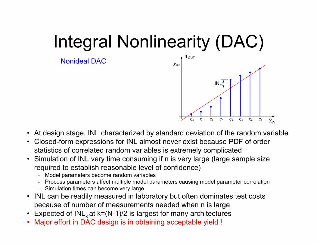
• At design stage, INL characterized by standard deviation of the random variable• Closed-form expressions for INL almost never exist because PDF of order
statistics of correlated random variables is extremely complicated• Simulation of INL very time consuming if n is very large (large sample size
required to establish reasonable level of confidence)− Model parameters become random variables− Process parameters affect multiple model parameters causing model parameter correlation− Simulation times can become very large
• INL can be readily measured in laboratory but often dominates test costs because of number of measurements needed when n is large
• Expected of INLk at k=(N-1)/2 is largest for many architectures• Major effort in DAC design is in obtaining acceptable yield !
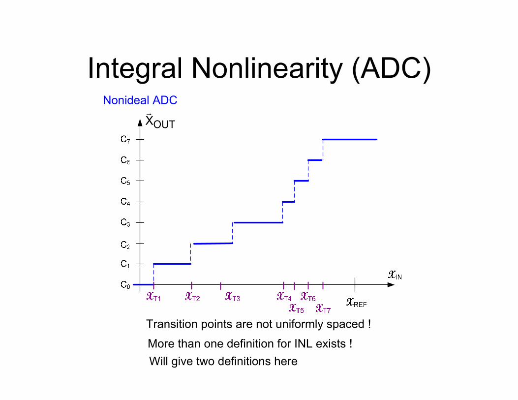
Integral Nonlinearity (ADC)Nonideal ADC
OUTX
Transition points are not uniformly spaced !
More than one definition for INL exists !Will give two definitions here

Integral Nonlinearity (ADC)Nonideal ADC
INX
( )INF INX X
Consider end-point fit line with interpreted output axis
( ) LSBINF IN IN T1X =m + -m
2⎛ ⎞⎜ ⎟⎝ ⎠
XX X X
( ) LSB
T7 T1
N-2m=
-X
X X
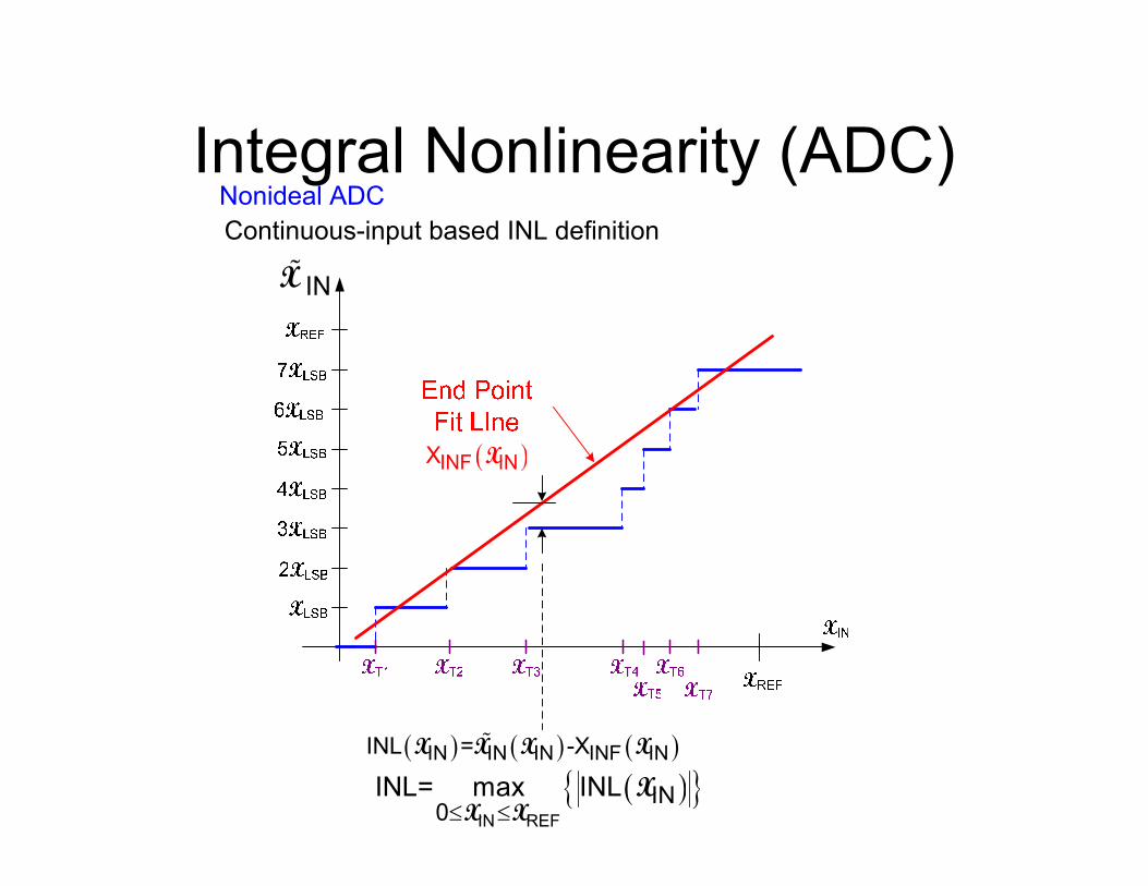
Integral Nonlinearity (ADC)Nonideal ADC
INX
( )INF INX X
( ) ( ) ( )IN IN IN INF ININL = -XX X X X
( ){ }IN REF
IN0
INL= max INL≤ ≤X X
X
Continuous-input based INL definition

Integral Nonlinearity (ADC)Nonideal ADC
INX
( )INF INX X
( ) ( ) ( )IN IN INF ININ
LSB
-XINL =
X X XX
X
( ){ }IN REF
IN0
INL= max INL≤ ≤X X
X
Continuous-input based INL definition
Often expressed in LSB
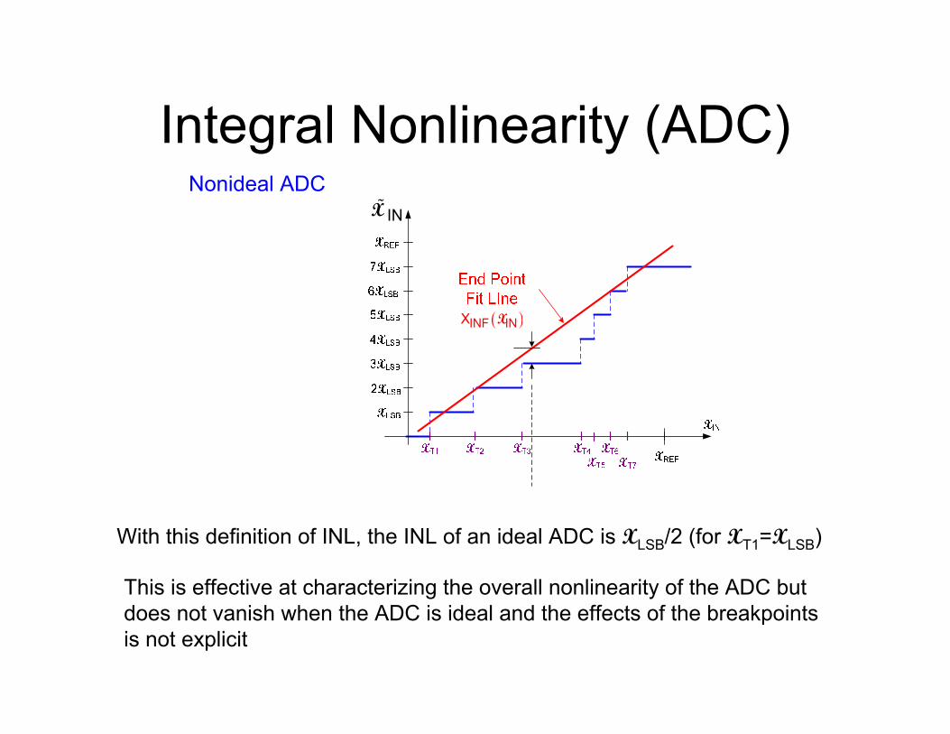
Integral Nonlinearity (ADC)Nonideal ADC
INX
( )INF INX X
With this definition of INL, the INL of an ideal ADC is XLSB/2 (for XT1=XLSB)
This is effective at characterizing the overall nonlinearity of the ADC butdoes not vanish when the ADC is ideal and the effects of the breakpointsis not explicit
Integral Nonlinearity (ADC)Nonideal ADC
XIN
OUTX
XREF
C0
C1
C2
C3
C4
C5
C6
C7
XT1 XT2 XT3 XT4XT5
XT6XT7
XIN
XFT1 XFT2 XFT3 XFT4 XFT5 XFT6 XFT7
INL3
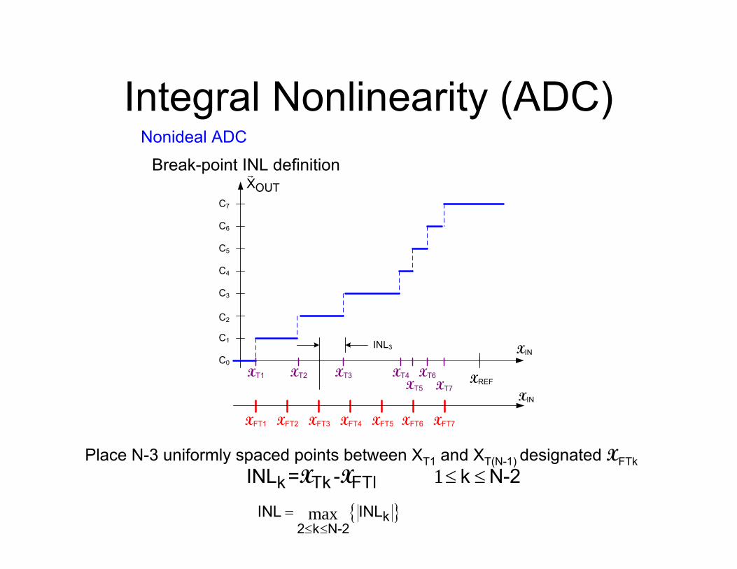
Break-point INL definition
Place N-3 uniformly spaced points between XT1 and XT(N-1) designated XFTk
{ }max k2 k N-2
INL INL≤ ≤
=
1k Tk FTlINL = - k N-2≤ ≤X X

Integral Nonlinearity (ADC)Nonideal ADC
XIN
OUTX
XREF
C0
C1
C2
C3
C4
C5
C6
C7
XT1 XT2 XT3 XT4XT5
XT6XT7
XIN
XFT1 XFT2 XFT3 XFT4 XFT5 XFT6 XFT7
INL3
Break-point INL definition
{ }max k2 k N-2
INL INL≤ ≤
=
Often expressed in LSB
1Tk FTlk
LSB
-INL = k N-2≤ ≤X X
X
For an ideal ADC, INL is ideally 0

Integral Nonlinearity (ADC)Nonideal ADC
OUTXBreak-point INL definition
{ }max k2 k N-2
INL INL≤ ≤
=
1Tk FTlk
LSB
-INL = k N-2≤ ≤X X
X
• INL is often the most important parameter of an ADC• INL1 and INLN-1 are 0 (by definition)• There are N-3 elements in the set of INLk that are of concern • INL is a random variable at the design stage• INLk is a random variable for 0<k<N-1• INLk and INLk+j are correlated for all k,j (not incl 0, N-1) for most architectures• Fit Line (for cont INL) and uniformly spaced break pts (breakpoint INL) are random
variables• INL is the N-3 order statistic of a set of N-3 correlated random variables (breakpoint
INL)

Integral Nonlinearity (ADC)Nonideal ADC
OUTXBreak-point INL definition
{ }max k2 k N-2
INL INL≤ ≤
=
1Tk FTlk
LSB
-INL = k N-2≤ ≤X X
X
• At design stage, INL characterized by standard deviation of the random variable• Closed-form expressions for INL almost never exist because PDF of order
statistics of correlated random variables is extremely complicated• Simulation of INL very time consuming if n is very large (large sample size
required to establish reasonable level of confidence)-Model parameters become random variables-Process parameters affect multiple model parameters causing model parameter correlation-Simulation times can become very large

Integral Nonlinearity (ADC)Nonideal ADC
OUTXBreak-point INL definition
{ }max k2 k N-2
INL INL≤ ≤
=
1Tk FTlk
LSB
-INL = k N-2≤ ≤X X
X
• INL can be readily measured in laboratory but often dominates test costs because of number of measurements needed when n is large
• Expected of INLk at k=(N-1)/2 is largest for many architectures• Major effort in ADC design is in obtaining an acceptable yield

INL-based ENOBConsider initially the continuous INL definition for an ADC where the INL of an
ideal ADC is XLSB/2
Assume
Define the LSB by
EQ
REF LSB n=
2
XX
ThusEQn
LSBINL=θ2 X
Since an ideal ADC has an INL of XLSB/2, express INL in terms of ideal ADC
1)2
EQ(n LSBXINL= θ2 + ⎛ ⎞⎡ ⎤ ⎜ ⎟⎢ ⎥⎣ ⎦ ⎝ ⎠Setting term in [ ] to 1, can solve for nEQ to obtain
( )EQ 2 R 21ENOB = n = log n -1-log
2θυ⎛ ⎞ =⎜ ⎟
⎝ ⎠
REF LSBRINL= θX = Xυ
where XLSBR is the LSB based upon the defined resolution
where nR is the defined resolution
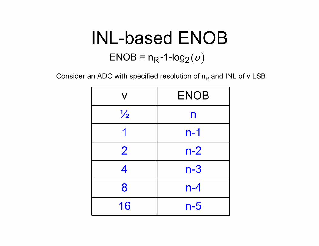
INL-based ENOB( )R 2ENOB = n -1-log υ
ν ENOB½ n1 n-12 n-24 n-38 n-4
16 n-5
Consider an ADC with specified resolution of nR and INL of ν LSB

End of Lecture 28