Embed Size (px)
Citation preview

High Brightness Electron Injectors for Light Sources - January 14-18 2007
Lecture 2D.H. Dowell, S. Lidia, J.F. Schmerge
• The objectives of this lecture are to define the basic electron emission statistics, describe the electrical potentials at the cathode surface, define the thermal emittance and derive the cathode emittance for thermal, photo-electric and field emission.
• This lecture begins with definitions of Maxwell-Boltzmann and Fermi-Dirac statistics, and discusses the electric fields at the cathode surface which the electron needs to overcome to escape. Then the physics of each of the three emission processes is described and their cathode emittances are derived.
Lecture 2:Electron Emission
and Cathode Emittance

High Brightness Electron Injectors for Light Sources - January 14-18 2007
Lecture 2D.H. Dowell, S. Lidia, J.F. Schmerge
Introduction• The electron density inside a cathode is many orders of magnitude
higher than that of the emitted electron beam.• This is seen by considering that the density of conduction band
electrons for metals is 1022 to 1023 electrons/cm3. Whereas the density of electrons in a 6 ps long, 200 micron diameter cylindrical bunch with 1 nC of charge is ~1014 electrons/cm3. Thus the transition from bound to free reduces the electron density by eight to nine orders of magnitude. In addition, the energy spread, or thermal energy of the electrons inside the cathode material is low. For example, in copper the energy spread near the Fermi energy is ~kBTor 0.02 eV at room temperature (300 degK). However, in order to release these cold, bound electrons, one needs to heat the cathode to approximately 2500 degK, resulting in a beam with a thermal energy of 0.20 eV.

High Brightness Electron Injectors for Light Sources - January 14-18 2007
Lecture 2D.H. Dowell, S. Lidia, J.F. Schmerge
Types of Electron Emission
• In general, the emission process determines the fundamental lower limit of the beam emittance. This ultimate emittance is often called the thermal emittance, due to the Maxwell-Boltzmann (MB) distribution of thermionic emitters. Strictly speaking, the term 'thermal emittance' should only be applied to thermionic emission, but the concept of thermal emittance or the intrinsic emittance of the cathode can be applied to the three forms of electron emission:
• 1. thermionic emission,
• 2. photo-electric emission
• 3. field emission.
High Brightness Electron Injectors for Light Sources - January 14-18 2007
Lecture 2D.H. Dowell, S. Lidia, J.F. Schmerge
Electron Statistics and the Emission Process
• Elementary particles in general can be classified as either bosons or fermions depending upon whether they have integer or half integer spin, respectively. Bosons obey classical Maxwell-Boltzmann statistics, while fermions follow Dirac-Fermi statistics. These statistics define the probability a particle occupies an given energy state based on the distribution of particles into energy intervals for the two particle types:
• 1. particles any number of which can share the same energy state, follow the Maxwell-Boltzmann distribution.
• 2. particles which cannot share the same energy state having only one particle per energy state, following the Fermi-Dirac distribution.

High Brightness Electron Injectors for Light Sources - January 14-18 2007
Lecture 2D.H. Dowell, S. Lidia, J.F. Schmerge
• The first particle type obeys classical Maxwell-Boltzmann (M-B) statistics with the energy distribution of occupied states given by,
• For the second particle type, of which electrons are a member being one-half spin fermions, the energy distribution of occupied states (DOS) is given by the Fermi-Dirac (F-D) function,
The Maxwell-Boltzmann and Fermi-Dirac Distributions
High Brightness Electron Injectors for Light Sources - January 14-18 2007
Lecture 2D.H. Dowell, S. Lidia, J.F. Schmerge
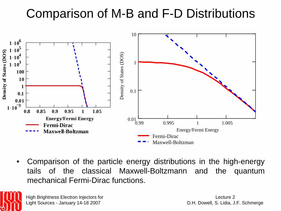
Comparison of M-B and F-D Distributions
• Comparison of the particle energy distributions in the high-energy tails of the classical Maxwell-Boltzmann and the quantum mechanical Fermi-Dirac functions.
0.99 0.995 1 1.0050.01
0.1
1
10
Fermi-DiracMaxwell-Boltzman
Energy/Fermi EnergyD
ensi
ty o
f Sta
tes (
DO
S)
0.8 0.85 0.9 0.95 1 1.051 .10 3
0.010.1
110
1001 .1031 .1041 .1051 .106
Fermi-DiracMaxwell-Boltzman
Energy/Fermi Energy
Den
sity
of S
tate
s (D
OS)

High Brightness Electron Injectors for Light Sources - January 14-18 2007
Lecture 2D.H. Dowell, S. Lidia, J.F. Schmerge
Fields Near the Cathode
0 2 4 6 8 10
1
0.5
0
0.5
ImageAppliedTotal
Distance from Cathode (nm)
Vol
tage
(vol
ts)
φ work−
0.5
0
0.5
1
1.5
Electron Density of States
Ener
gy re
lativ
e to
Fer
mi E
nerg
y (e
V)
work function, φwork
Electron Density of States
Ener
gy R
elat
ive
to
Ferm
i Ene
rgy
(eV
)
occupied statesM-B Distribution
F-D DistributionDistance from Cathode (nm)
Φ = φwork - φschottky
xm
q’d
-exx
e
Metal Cathode
Vacuum
φschottky

High Brightness Electron Injectors for Light Sources - January 14-18 2007
Lecture 2D.H. Dowell, S. Lidia, J.F. Schmerge
Thermionic Emission(1)In order for an electron to escape a metal it needs to have sufficient
kinetic in the direction of the barrier to overcome the work function,
1 1.2 1.4 1.6 1.81 .10 121 .10 111 .10 101 .10 91 .10 81 .10 71 .10 61 .10 51 .10 41 .10 3
0.010.1
110
Energy/(Fermi Energy)
Ef φwork+
T=300degK
T=2500degK
T=3000degKn e(E/E
F)/n
0
1 1.2 1.4 1.6 1.81 .10 121 .10 111 .10 101 .10 91 .10 81 .10 71 .10 61 .10 51 .10 41 .10 3
0.010.1
110
Energy/(Fermi Energy)
Ef φwork+
T=300degK
T=2500degK
T=3000degKn e(E/E
F)/n
0

High Brightness Electron Injectors for Light Sources - January 14-18 2007
Lecture 2D.H. Dowell, S. Lidia, J.F. Schmerge
Thermionic Emission(2)• Assume that the cathode has an applied electric field
large enough to remove all electrons from the surface, so there are no space charge effect, but low enough to not affect the barrier height. Then the thermionic current density for a cathode at temperature,
1 1.2 1.4 1.6 1.81 .10 121 .10 111 .10 101 .10 91 .10 81 .10 71 .10 61 .10 51 .10 41 .10 3
0.010.1
110
Energy/(Fermi Energy)
Ef φwork+
T=300degK
T=2500degK
T=3000degKn e(E/E
F)/n
0
1 1.2 1.4 1.6 1.81 .10 121 .10 111 .10 101 .10 91 .10 81 .10 71 .10 61 .10 51 .10 41 .10 3
0.010.1
110
Energy/(Fermi Energy)
Ef φwork+
T=300degK
T=2500degK
T=3000degKn e(E/E
F)/n
0

High Brightness Electron Injectors for Light Sources - January 14-18 2007
Lecture 2D.H. Dowell, S. Lidia, J.F. Schmerge
Thermionic Emission (3)• As discussed above and shown in Figure 1, the interactions
involving the high energy electrons in the tail of the Fermi-Dirac density of states allows it's replacement with the classical, Maxwell-Boltzmann distribution,
•Performing these simple integrals gives the thermioniccurrent density,

High Brightness Electron Injectors for Light Sources - January 14-18 2007
Lecture 2D.H. Dowell, S. Lidia, J.F. Schmerge
Thermionic Emission(4)• Or with a small change in the leading constants, gives
the Richardson-Dushman equation for thermionicemission [Reiser, p 8],
• Here A is 120 amp/cm2/degK2, and (1-r) accounts for the reflection of electrons at the metal surface. The reflection and refraction of electrons as they transit the surface is discussed in a later section. In terms of fundamental quantities, the universal constant A is ["Solid State Physics", by Ashcroft and Mermin, p. 363]

High Brightness Electron Injectors for Light Sources - January 14-18 2007
Lecture 2D.H. Dowell, S. Lidia, J.F. Schmerge
Thermionic Emittance (1)• The velocity distribution for thermally emitted electrons is obtained
from the derivative of Maxwell-Boltzmann particle distribution,
1 .10 6 1 .10 5 1 .10 4 1 .10 3 0.01 0.1 1 10
300 degress K2500 degrees K
Transverse Energy (eV)
Max
wel
l-Bol
tzm
an D
istri
butio
n (a
rb) • Maxwell-Boltzmann electron
energy distributions at 300 degKwhere the rms electron energy spread is 0.049 eV, and at 2500 degK corresponding to an rmsenergy spread of 0.41 eV. The initial spread in transverse velocity due to the electron temperature gives the beam angular divergence and hence its thermionic emittance.

High Brightness Electron Injectors for Light Sources - January 14-18 2007
Lecture 2D.H. Dowell, S. Lidia, J.F. Schmerge
Thermionic Emittance (2)• Following Lawson [Lawson, p. 209], we assume the normalized
emittance is evaluated close to the cathode surface where the electron flow is still laminar (no crossing of trajectories) and any correlation between position and angle can be ignored. In this case, normalized cathode emittance is given by,
• The root-mean-square (rms) beam size, σx, is given by the transverse beam distribution which for a uniform radial distribution with radius R is R/2. The rms divergence is given by
• The normalized, rms thermal emittance is then
Reiser, p56-66

High Brightness Electron Injectors for Light Sources - January 14-18 2007
Lecture 2D.H. Dowell, S. Lidia, J.F. Schmerge
Thermionic Emittance (3)• The mean squared transverse velocity for a M-B velocity distribution
is,
• Therefore the thermionic emittance of a Maxwell-Boltzmann distribution at temperature, T, is

High Brightness Electron Injectors for Light Sources - January 14-18 2007
Lecture 2D.H. Dowell, S. Lidia, J.F. Schmerge
Thermionic Emittance (4)• The divergence part of the cathode emittance contains all the
physics of both the emission process and the cathode material properties and as such summarizes much of the interesting physics of the emission process. The beam size in coordinate space simply traces out the angular distribution to form the transverse phasespace distribution as illustrated.
σx’
x, σx x
x’
σx
σx’σx’
x, σx x
x’
σx
σx’x, σx x
x’
σx
σx
σx’
Distribution in Phase SpaceDistribution in
Coordinate Space

High Brightness Electron Injectors for Light Sources - January 14-18 2007
Lecture 2D.H. Dowell, S. Lidia, J.F. Schmerge
Thermionic Emission (5)• Given that σx depends upon the particular transverse distribution
being used, there is often a serious ambiguity which arises whenexpressing the thermal emittance in terms of "microns/mm". The confusion results in not knowing whether rms or flat top radii are used for the transverse radius. Therefore we suggest quoting a quantity called the normalized divergence, which for thermionicemission is

High Brightness Electron Injectors for Light Sources - January 14-18 2007
Lecture 2D.H. Dowell, S. Lidia, J.F. Schmerge
Photo-Electric Emission(1)• Photoelectric emission from a metal can be described by the three
steps of the Spicer model:1. Photon absorption by the electron2. Electron transport to the surface3. Escape through the barrier
Metal Vacuum
1)Photon absorbed
2)Electrons move to surface
3)Electrons escape to vacuum
Direction normal to surface
Ene
rgy
FermiEnergy
Potential barrier due to spillout electrons
Optical depthλphoton
e- e- e-
occupiedvalencestates
Metal Vacuum
1)Photon absorbed
2)Electrons move to surface
3)Electrons escape to vacuum
Direction normal to surface
Ene
rgy
Ene
rgy
FermiEnergy
Potential barrier due to spillout electrons
Optical depthλphoton
e- e- e-e-
occupiedvalencestates

High Brightness Electron Injectors for Light Sources - January 14-18 2007
Lecture 2D.H. Dowell, S. Lidia, J.F. Schmerge
Photo-Electric Emission (2)• Thermalization time of electrons in a metal as measured in a pump-
probe experiment:
Fann et al., “Observation of the thermalization of electrons in a metal excited by femtosecond optical pulses,” in Ultrafast Phenomenona, ed. J.-L. Martin, A. Meigus, G.A. Mourou and A.H. Zewail, Springer Verlag 1993, p331-334.

High Brightness Electron Injectors for Light Sources - January 14-18 2007
Lecture 2D.H. Dowell, S. Lidia, J.F. Schmerge
∫ ∫∫
∫ ∫∫∞
− −
∞
−+−
Φ+−+
Φ+−+
−=
ω
π
ωφ
π
θ
θωω
θωθωω
ωω
h
h
hh
hh
F
effF
EFDFD
Eee
EFDFD
ddEfENEfENdE
dEFdEfENEfENdE
RQE2
0
1
1
2
0
1
)(cos
)(cos)()())(1)((
),,()(cos)()())(1)((
))(1()( max
Elements of the Three-Step Photoemission Model
Fermi-Dirac distribution at 300degK
schottkyeff φφφ −=TkEEFD BFeEf /)(1
1)( −+=
EF EF+φeffEF+φeff-hω
hω
Bound electrons
EF+hω
hω−φeff
E E+hω
φeff
hω
Emitted electrons
Step 1: Absorption of photon Step 3: Escape over barrierStep 2: Transport to surface
Electrons lose energyby scattering, assumee-e scatteringdominates,Fe-e is the probability the electron makes it to thesurface without scattering
Escape criterion: effFnormal Em
p φ+>2
2
θ
⊥p
)(2 ωh+= Emptotal
ωφ
θh+
+== ⊥
EE
pp effF
totalmaxcos
θω cos)(2 h+= Empnormal
Photo-Electric Emission (3)

High Brightness Electron Injectors for Light Sources - January 14-18 2007
Lecture 2D.H. Dowell, S. Lidia, J.F. Schmerge
The optical skin depth depends upon wavelength and is given by,
where k is the imaginary part of the complex index of refraction,
and λ is the free space photon wavelength.
Step 1: Absorption of Photon
190 200 210 220 230 240 250 260 270 280 290 3000.4
0.42
0.44
0.46
0.48
Wavelength (nm)
Rel
ectiv
ity
180 200 220 240 260 280 300100
110
120
130
140
150
Wavelength (nm)
Opt
ical
Abs
orpt
ion
Leng
th (a
ngst
rom
s)
Optical absorption length and reflectivity of copper
The reflectivity is given by the Fresnel relationin terms of the real part of the index of refraction,
kopt πλλ
4=
ikn +=η
)),(),((tyReflectivi 21 innR θωω=

High Brightness Electron Injectors for Light Sources - January 14-18 2007
Lecture 2D.H. Dowell, S. Lidia, J.F. Schmerge
Step 2: Transport to the Surface
Fe-e: Probability electron at depth s, absorbs a photon and escapes without scattering.
⎟⎟⎠
⎞⎜⎜⎝
⎛+−
−= eeopts
opt
esf λλ
λ
111)(
ee
optee dssfF
−
∞
−
+== ∫
λλ
1
1)(0
metal vacuum
optse λ/−
s
effeeopteeopt ss
ss eeee λλλλλ /11
// −⎟⎟⎠
⎞⎜⎜⎝
⎛+−
−− == −−
metal vacuum
optse λ/−
s
effeeopteeopt ss
ss eeee λλλλλ /11
// −⎟⎟⎠
⎞⎜⎜⎝
⎛+−
−− == −−
opt
s
s
s
excited
opt
opt
opt e
dse
esPλ
λ
λ
λ /
0
/
1
)(−
∞−
⎟⎟⎠
⎞⎜⎜⎝
⎛−
==
∫
⎟⎟⎠
⎞⎜⎜⎝
⎛+
==
∫
∫ −
−
ωφφω
λλ
ωλ ω
φ
ω
φ
h
hh
h
h
effeff
mm
ee
eeE
dE
dEE
eff
eff
1
12)(
)(2/3
Assume the electron-electron scattering lengthcan be averaged over energy:
4 5 6 7 8 9 10
20
40
60
80
100
Energy above Fermi Level (eV)
e-e
Scat
teri
ng L
engt
h (a
ngst
rom
s)
2/3
')()'( ⎟
⎠⎞
⎜⎝⎛= −− E
EEE m
meeee λλ
Krolikowski & Spicer, 1970

High Brightness Electron Injectors for Light Sources - January 14-18 2007
Lecture 2D.H. Dowell, S. Lidia, J.F. Schmerge
Escape criterion: effFnormal Em
p φ+>2
2
ωφ
θh+
+==
EE
pp effF
total
normalmaxcos
θ
⊥p
)(2 ωh+= Emptotal
θω cos)(2 h+= Empnormal
Step 3: Escape Over the Barrier
While photoemission is regarded quantum mechanical effect due toquantization of photons, emission itself is classical. I.e., electrons do not tunnel through barrier, but classically escape over it.
ωh+Eφω −−+ FEE h
φ+FE
inmax,θ
ωh+Eφω −−+ FEE h
φ+FE
inmax,θ

High Brightness Electron Injectors for Light Sources - January 14-18 2007
Lecture 2D.H. Dowell, S. Lidia, J.F. Schmerge
Derivation of QE
∫ ∫∫
∫ ∫∫∞
− −
∞
−+−
Φ+−+
Φ+−+
−=
ω
π
ωφ
π
θ
θωω
θωθωω
ωω
h
h
hh
hh
F
effF
EFDFD
Eee
EFDFD
ddEfENEfENdE
dEFdEfENEfENdE
RQE2
0
1
1
2
0
1
)(cos
)(cos)()())(1)((
),,()(cos)()())(1)((
))(1()( max
( ) ( )∫∫∫
∫∫∫
Φ
Φ
−=
−−
+
+−+
− π
ω
π
ωφωφ
θ
θ
ωωω2
0
1
1
2
0
1
)(cos
)(cos
)(1)(dddE
dddE
FRQEF
F
efff
F
effF
E
E
EE
E
E
ee
h
h
h
Approximate F-D with step function since kBT<<EF :
The QE is then given by: ( )2
2/3
212
1)(2
)(1
)(1)(⎥⎥⎦
⎤
⎢⎢⎣
⎡
+
+−
+
⎟⎟
⎠
⎞
⎜⎜
⎝
⎛++
−=
−
ωφ
ωω
ωφφω
λωλ
ωωhh
h
h
h F
effFF
eff
m
eff
mee
optEEE
EE
RQE
• D. H. Dowell, K.K. King, R.E Kirby and J.F. Schmerge, "In situ cleaning of metal cathodes using a hydrogen beam," PRST-AB 9, 063502 (2006)
TkEEFD BFeEf /)(1
1)( −+=
EF EF+φeffEF+φeff-hω
hω
Bound electrons
EF+hω
hω−φeff
E E+hω
φeff
hω
Emitted electrons
TkEEFD BFeEf /)(1
1)( −+=
EF EF+φeffEF+φeff-hω
hω
Bound electrons
EF+hω
hω−φeff
E E+hω
φeff
hωhω
Emitted electronsState Occupation
Number
State Energy
TkEEFD BFeEf /)(1
1)( −+=
EF EF+φeffEF+φeff-hω
hω
Bound electrons
EF+hω
hω−φeff
E E+hω
φeff
hω
Emitted electrons
TkEEFD BFeEf /)(1
1)( −+=
EF EF+φeffEF+φeff-hω
hω
Bound electrons
EF+hω
hω−φeff
E E+hω
φeff
hωhω
Emitted electronsState Occupation
Number
State Energy
High Brightness Electron Injectors for Light Sources - January 14-18 2007
Lecture 2D.H. Dowell, S. Lidia, J.F. Schmerge
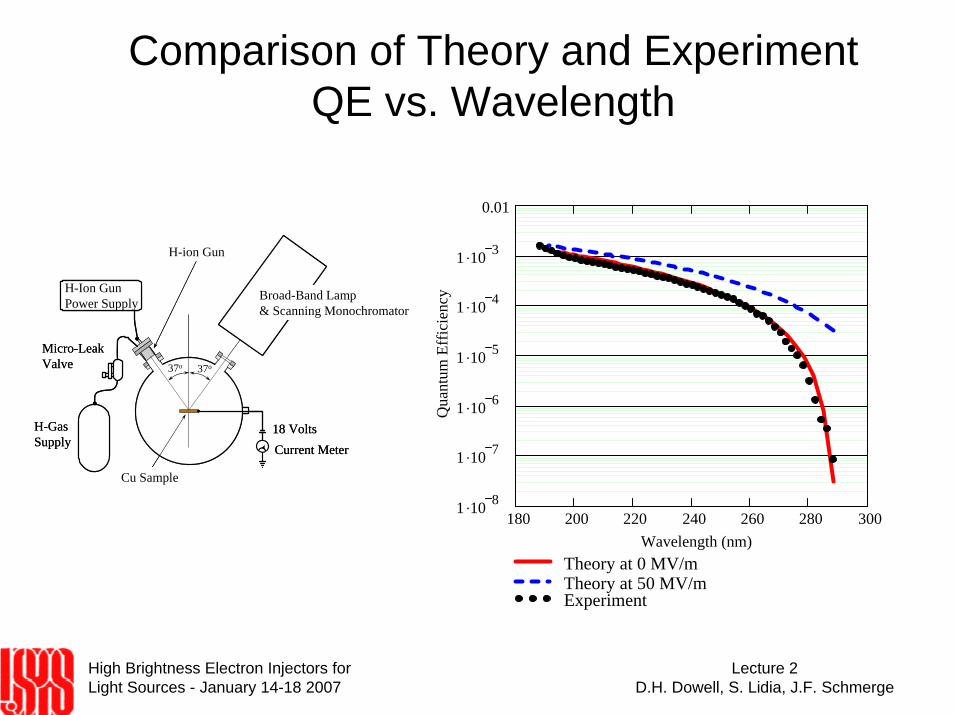
Comparison of Theory and Experiment QE vs. Wavelength
Broad-Band Lamp& Scanning Monochromator
H-GasSupply
Micro-LeakValve
18 VoltsCurrent Meter
Cu Sample
37o 37o
H-ion Gun
H-Ion Gun Power Supply Broad-Band Lamp
& Scanning Monochromator
H-GasSupply
Micro-LeakValve
18 VoltsCurrent Meter
Cu Sample
37o 37o
H-ion Gun
H-Ion Gun Power Supply
180 200 220 240 260 280 3001 .10 8
1 .10 7
1 .10 6
1 .10 5
1 .10 4
1 .10 3
0.01
Theory at 0 MV/mTheory at 50 MV/mExperiment
Wavelength (nm)
Qua
ntum
Eff
icie
ncy

High Brightness Electron Injectors for Light Sources - January 14-18 2007
Lecture 2D.H. Dowell, S. Lidia, J.F. Schmerge
Photo-Electric Emittance (1)• The mean square of the transverse momentum is related to the
electron distribution function, g(E,θ,φ), just inside the cathode surface,
• The g-function and the integration limits depend upon the emission processes. We assume for the three-step photo-emission model that g depends only on energy,
High Brightness Electron Injectors for Light Sources - January 14-18 2007
Lecture 2D.H. Dowell, S. Lidia, J.F. Schmerge
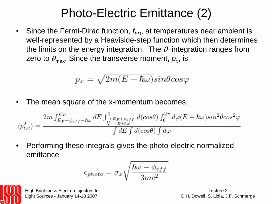
Photo-Electric Emittance (2)• Since the Fermi-Dirac function, fFD, at temperatures near ambient is
well-represented by a Heaviside-step function which then determines the limits on the energy integration. The θ−integration ranges from zero to θmax. Since the transverse moment, px, is
• The mean square of the x-momentum becomes,
• Performing these integrals gives the photo-electric normalized emittance

High Brightness Electron Injectors for Light Sources - January 14-18 2007
Lecture 2D.H. Dowell, S. Lidia, J.F. Schmerge
Photo-Electric Emittance (3)
• Normalized divergence vs. photon energy for various applied fields
4 4.5 5 5.5 60
0.2
0.4
0.6
0.8
1
1.2
0 MV/m50 MV/m100 MV/m
Photon Energy (eV)
Phot
oele
ctri
c N
orm
aliz
ed D
iver
genc
e (m
R)
4.866

High Brightness Electron Injectors for Light Sources - January 14-18 2007
Lecture 2D.H. Dowell, S. Lidia, J.F. Schmerge
Photo-Electric Emittance & QE
0.2
0.4
0.6
0.8
1
1.2
1.4
Phot
o-El
ectr
ic D
iver
genc
e (m
rad)
180 200 220 240 260 280 3001 .10 8
1 .10 7
1 .10 6
1 .10 5
1 .10 4
1 .10 3
0.01
Photon Wavelength (nm)
Qua
ntum
Eff
icie
ncy
The photo-electric normalized divergence (top, red) and the quantum efficiency (bottom, red) vs. photon wavelength for copper. The green ellipses show the range of QE and cathode emittance measured during commissioning of the LCLS injector.

High Brightness Electron Injectors for Light Sources - January 14-18 2007
Lecture 2D.H. Dowell, S. Lidia, J.F. Schmerge
Field Emission (1)• Field emission occurs when electrons tunnel through the barrier
potential under the influence of very high fields of 109 V/m or more. Since emission is by tunneling the effect is purely quantum mechanical and requires an extremely high electric field to lower the barrier enough for useful emission.
• where the supply function, n(Ex,T), is the flux of electrons incident upon the barrier with energies between Ex and Ex + dEx. The barrier is same as that shown earlier and is determined by the work function, the image charge and the applied electric field, E0. The transmission of electrons through this barrier is given by the transparency function, D(Ex,E0).

High Brightness Electron Injectors for Light Sources - January 14-18 2007
Lecture 2D.H. Dowell, S. Lidia, J.F. Schmerge
Field Emission (2)• The transparency function was solved by Nordheim for the barrier
produced by the image charge and the applied field (Schottkypotential),
• The result is
• θ(y) is the Nordheim function which to a good approximation is given by

High Brightness Electron Injectors for Light Sources - January 14-18 2007
Lecture 2D.H. Dowell, S. Lidia, J.F. Schmerge
Field Emission (3)• The supply function for a Fermi-Dirac electron gas was also derived
by Nordheim,
• Combining the supply and transparency functions gives the electron energy spectrum,
“Field Emission in Vacuum Microelectronics,” G. Fursey, Kluwer Academic/Plenum, 2005

High Brightness Electron Injectors for Light Sources - January 14-18 2007
Lecture 2D.H. Dowell, S. Lidia, J.F. Schmerge
Field Emission (4)• Electron spectra for field emission electrons for various applied fields.
Left: Electron emission spectra plotted with a linear vertical scale and with arbitrarily normalization to illustrate the spectral shapes. Right: The spectral yields plotted logarithmically to illustrate the strong dependence of yield and shape upon applied field.
6 8 10 12 140
1 .104
2 .104
3 .104
10^10 V/m5x10^9 V/m3x10^9 V/m
Energy (eV)
Elec
tron
Yie
ld (r
el)
6 8 10 12 141 .10 121 .10 111 .10 101 .10 91 .10 81 .10 71 .10 61 .10 51 .10 41 .10 30.01
0.11
10100
1 .1031 .1041 .105
10^10 V/m5x10^9 V/m3x10^9 V/m
Energy (eV)
Elec
tron
Spec
tra (r
el)
6 8 10 12 140
1 .104
2 .104
3 .104
10^10 V/m5x10^9 V/m3x10^9 V/m
Energy (eV)
Elec
tron
Yie
ld (r
el)
6 8 10 12 141 .10 121 .10 111 .10 101 .10 91 .10 81 .10 71 .10 61 .10 51 .10 41 .10 30.01
0.11
10100
1 .1031 .1041 .105
10^10 V/m5x10^9 V/m3x10^9 V/m
Energy (eV)
Elec
tron
Spec
tra (r
el)

High Brightness Electron Injectors for Light Sources - January 14-18 2007
Lecture 2D.H. Dowell, S. Lidia, J.F. Schmerge
Field Emission Emittance• Armed with the energy spectra the rms energy spread and the field
emission emittance are numerically computed for external fields between 109 and 1010 Volts/m. (Solved numerically.)
2 .109 4 .109 6 .109 8 .109 1 .10100
0.5
1
1.5
2
2.5
Field Emission Emittance (microns/mm)rms Energy Spread (eV)
External Field (V/m)

High Brightness Electron Injectors for Light Sources - January 14-18 2007
Lecture 2D.H. Dowell, S. Lidia, J.F. Schmerge
Field Enhancement Factor, β• In field emission the electron yield is exponentially sensitive to the
external field and any significant current requires fields in excess of 109 V/m. Such high fields are difficult to achieve but are possible using pulsed high voltages and/or field-enhancing, sharp emitters.
“High Voltage Vacuum Insulation, Basic Concepts and Technological Practice,”Ed. Rod Latham, Academic Press 1995
0EE β=

High Brightness Electron Injectors for Light Sources - January 14-18 2007
Lecture 2D.H. Dowell, S. Lidia, J.F. Schmerge
• The space charge limit and cathode emittance

High Brightness Electron Injectors for Light Sources - January 14-18 2007
Lecture 2D.H. Dowell, S. Lidia, J.F. Schmerge
What A Real Cathode Looks Like!
1.4 mm diameterIlluminated by drive laser
LCLS gun cathode after 5 months of operation
High Brightness Electron Injectors for Light Sources - January 14-18 2007
Lecture 2D.H. Dowell, S. Lidia, J.F. Schmerge
Lecture 2 Summary• This lecture derived the cathode emittances for the three emission
processes: thermionic, photo-electric and field emission. Rather than using the term, thermal emittance, we prefer to use the general term of cathode or intrinsic emittance for any emission process. And instead define the intrinsic emittance for each of the three emission processes. The intrinsic emittance for thermionic emission is approximately 0.3 microns/mm for a cathode temperature of 2500 degK. The photo-electric emittance for a copper cathode ranges between 0.5 to 1 micron/mm depending upon the photon wavelength, and the emittance was shown to be proportional to the quantum efficiency. The field-emission emittance is found to vary between 0.5 to 2 microns/mm for fields from 109 to 1010 V/m, and hence has larger emittance for the same source size than the other two processes.