Embed Size (px)
Citation preview

Pingki Datta, Lecturer, Department of Civil Engineering, KUET. 1
Lecture 04

Pingki Datta, Lecturer, Department of Civil Engineering, KUET.
2
Plumbing of Multistoried Building

Pingki Datta, Lecturer, Department of Civil Engineering, KUET. 3
References 1) World Health Organization (2015). Design of Plumbing Systems for
Multi-storey Buildings. Addressing Http://Www. Who. Int/Water_sanitation_health/Hygiene/Plumbing14. Pdf Accessed on Feb, 10.
2) Building Engineering and Systems Design. Springer Science & Business Media. Frederick S. Merritt. & James Ambrose (2012).
3) Building design and construction handbook (6th ed). New York: McGraw-Hill. Frederick S. Merritt. & Jonathan T. Ricketts (Eds.). (2001).
4) Building Systems for Interior Designers. John Wiley & Sons. Corky Binggeli, A.S.I.D. (2003).

Pingki Datta, Lecturer, Department of Civil Engineering, KUET. 4

Pingki Datta, Lecturer, Department of Civil Engineering, KUET. 5
Design of plumbing systems for multi-storey buildings
• For plumbing purposes, the term “multi-storey” is applied to
buildings that are too tall to be supplied throughout by the normal
pressure in the public water mains. These buildings have particular
needs in the design of their sanitary drainage and venting systems.
Water main supply pressures of 8–12 metres (25–40 feet) can
supply a typical two-storey building, but higher buildings may need
pressure booster systems. In hilly areas, the drinking-water supply
pressures will vary depending on the ground elevation.

Pingki Datta, Lecturer, Department of Civil Engineering, KUET.
6
Plumbing System in High Rise Building
• In these cases, the water authority may have to specify areas where
particular supply pressures can be relied upon for the design and
operation of buildings. Where a building of three or more storeys is
proposed a certificate should be obtained from the drinking-water
supply authority guaranteeing that the present and future public
drinking-water supply pressure will be adequate to serve the
building. If the public water pressure is inadequate, suitable means
shall be provided within the building to boost the water pressure.

7

Pingki Datta, Lecturer, Department of Civil Engineering, KUET. 8
Systems for boosting water pressure
Pressure-boosting systems can be of several different types: pumping from a ground level or basement gravity tank to a gravity
roof tank; pumping from a gravity storage tank or public water main into a
hydro pneumatic pressure tank that uses captive air pressure to provide adequate drinking-water supply pressure;
installation of booster pump sets consisting of multiple staged
pumps or variable speed pumps that draw water directly from a gravity storage tank or the public water main. Multistage booster pump sets typically include discharge pressure regulating valves to maintain a constant drinking-water supply pressure.

Pingki Datta, Lecturer, Department of Civil Engineering, KUET. 9
Systems for boosting water pressure
Written approval should be obtained from the appropriate authority
before any pump or booster is connected to the supply. Where booster
pump sets are permitted to draw directly from public water mains, the
public drinking-water supply must be adequate to meet the peak
demands of all buildings in the area. Otherwise, there is a high risk of
backflow and subsequent contamination of the mains from buildings
not equipped with a booster pump. Building booster pumps are not a
solution to the problem of inadequate drinking-water supply.

Pingki Datta, Lecturer, Department of Civil Engineering, KUET. 10
Systems for boosting water pressure
Where public drinking-water supply systems are overburdened and
cannot provide adequate pressure on a continuous basis, water must
be stored on site during periods when adequate pressure is available
to fill a gravity storage tank. The size of the storage tank will vary
according to the daily water demand of the building, and the
availability of adequate pressure available in the public water mains. It
should not be excessively oversized to avoid stagnation due to
inadequate turnover.

Pingki Datta, Lecturer, Department of Civil Engineering, KUET. 11
Systems for boosting water pressure
Multi-storey buildings can usually be divided into zones of water
pressure control. The lower two to three storeys can generally be
supplied directly from the pressure in the public water main. Upper
storeys, usually in groups of five to eight storeys, can be supplied from
pressure-boosted main risers through a pressure reduction valve for
each group.

Pingki Datta, Lecturer, Department of Civil Engineering, KUET. 12
Systems for boosting water pressure
Systems can be up-fed or down-fed. Up-fed systems usually originate
from a pressure booster pump set or hydro pneumatic tank in the
basement of the building. Down-fed systems usually originate from a
rooftop gravity tank. Where a building is divided into water pressure
zones, care must be taken not to cross-connect the piping between
two or more zones. This is a particular problem when domestic hot
water is recirculated from a central supply system.

Pingki Datta, Lecturer, Department of Civil Engineering, KUET. 13
Systems for boosting water pressure
Where hydropneumatic tanks are used for storage, the tank is filled
to one third to a half full by a float level device that controls the
drinking-water supply source (a well pump or pressure booster
pump). The pressure is maintained at the desired operating level by
an air compressor. As the building uses water from the tank, the
water level and air pressure drop. When the water level drops to
the “on” setting of the float level control, the well pump or booster
pump starts and raises the water level in the tank to the “off” level.
This restores the pressure in the tank.

Pingki Datta, Lecturer, Department of Civil Engineering, KUET. 14
Systems for boosting water pressure If some of the captive air above the water has been absorbed by the
water, the air compressor starts and restores the air charge, raising the
system pressure to the normal level. Hydropneumatic tanks are typically
made of steel or fibreglass and must be rated for the system operating
pressure. Steel tanks must have a protective coating of suitable
composition for drinking-water contact on the inside to protect the tank
from corrosion and avoid contaminating the water. They should be
checked on a regular basis to ensure that the protective coating is intact
and the water remains potable.

Pingki Datta, Lecturer, Department of Civil Engineering, KUET. 15
Systems for boosting water pressure
Smaller hydropneumatic tanks can also be used to help control pressure
booster pumps, allowing them to be cycled on and off by a pressure
switch. The captive air within the tank keeps the system pressurized
while the pump is off. When the water pressure drops to the “on”
pressure setting, the pump starts and raises the volume and pressure of
the water in the tank. No air compressor is needed where tanks have a
flexible diaphragm between the air and the water in the tank, charged
with air at initial start-up. The size of pressure tanks for booster pumps
must match the capacity of the pump and the peak system demand so
that the pump “off” cycle is longer than the “on” cycle and the pump
does not cycle too frequently.

Pingki Datta, Lecturer, Department of Civil Engineering, KUET. 16
Drainage systems- Drainage system considerations
In the drainage system for a multi-storey building, the drains from the plumbing fixtures are connected to vertical drain stacks that convey the waste and sewage to below the lowest floor of the building. The fixture drain traps must be vented to prevent their water trap seal from being siphoned by negative pressure or blown out by positive pressure in the drain piping. The fixture vent pipes must extend through the roof to outdoors. They can be run individually or be combined into one or more vents through the roof. Where buildings are over 10 storeys high, the drainage stacks require relief vent connections at specified intervals from the top, and connected to a vent stack that terminates above the roof. This relieves and equalizes the pressure in the drainage stack to maintain the water seal in traps serving plumbing fixtures.

Pingki Datta, Lecturer, Department of Civil Engineering, KUET. 17
Drainage systems- Drainage system considerations
Wherever possible, the sanitary drainage system from a building should discharge to the public sewer by gravity. All plumbing fixtures located below ground level should be pumped into the public sewer or the drainage system leading to the sewer. The pump line should be as short as possible and looped up to a point not less than 0.6 meters (24 inches) above ground level to prevent back siphonage of sewage. The pump discharge rate should be controlled so as not to cause scouring of the internal bore of the pump line or the drainage or sewer system into which it discharges. High-velocity discharge rates may also cause the flooding of adjoining plumbing fixtures or overloading of the sewer itself. The sump pits for sewage pumps must have sealed covers, be vented to outdoors and have automatic level controls and alarms. Sewage pumps in multiple dwellings and in multi-storey dwellings should be duplex, with each pump having 100% of the required pumping capacity for the building. Alternatively, an approved vacuum drainage system may be considered.

Pingki Datta, Lecturer, Department of Civil Engineering, KUET. 18
Drainage systems- Vacuum drainage systems
In a vacuum drainage system, the differential pressure between the
atmosphere and the vacuum becomes the driving force that propels the
wastewater towards the vacuum station. Table 1 provides a summary of
the advantages and disadvantages of vacuum drainage systems. Table 2
provides information on specific installation and operation
requirements. Vacuum drainage systems should be considered when
one or more of the following conditions exist:
• water shortage;
• limited sewerage capacity;
• where separation of black water and grey water is desired;
• where drainage by gravity becomes impractical;

Pingki Datta, Lecturer, Department of Civil Engineering, KUET. 19
Drainage systems- Vacuum drainage systems
• in penal installations where isolation and control of the appliances is
necessary to prevent concealment of weapons and drugs;
• unstable soil or flat terrain;
• where a high water table exists;
• in hospitals, hotels, office buildings or other areas where congested
usage
occurs, and flexibility in pipe routing is required to drain appliances;
• restricted construction conditions;
• building refurbishment.

Pingki Datta, Lecturer, Department of Civil Engineering, KUET. 20
Hot water and other dual supply systems
Dual drinking-water supply systems are those in which two different grades of water are available in separate piping systems. An example is the provision of a tap at a sink supplying water directly from the incoming water service while all other fixtures are fed from a storage tank. In developed countries, the most common is a secondary system of piping carrying hot water to sink, washbasin and bath. Occasionally a water softener is installed to treat part of a domestic system, but apart from these cases dual drinking-water supply systems are rarely found within single dwellings. An approach to water conservation being introduced in some communities is to recycle greywater to an outside tap for irrigation uses. A principal concern of all dual systems is the assurance that no cross-connections have occurred during installation or repair.

21
Drainage systems- Vacuum drainage systems
TABLE 1: ADVANTAGES AND DISADVANTAGES OF VACUUM SYSTEMS (VERSUS GRAVITY SYSTEMS)

22
Drainage systems- Vacuum drainage systems
TABLE 2: COMPARISON OF INSTALLATION AND OPERATION REQUIREMENTS OF DRAINAGE SYSTEMS

Pingki Datta, Lecturer, Department of Civil Engineering, KUET. 23

24
Water storage vessels
Separate water storage vessels are an integral part of many dual supply systems. This section deals with requirements for the storage of water supplied from the water main or other drinking-water sources. In the design of these systems, it is important to ensure that the required air gap is established between the drinking water supply inlet and the overflow spill level of the fixture. Water storage tanks are appropriate for use in the following circumstances:

Pingki Datta, Lecturer, Department of Civil Engineering, KUET.
25

26
Water storage vessels

27
Water storage vessels

28
Labeling and color coding of non-drinking-water supply systems

29
Labeling and color coding of non-drinking-water supply systems

30
Labeling and color coding of non-drinking-water supply systems

31

32
Situations where there is a risk of cross-connection

33
Agricultural and horticultural properties
Catering and allied trade installations

34
Domestic installations

35
Health and sanitary service installations

36
Industrial and commercial installations

37
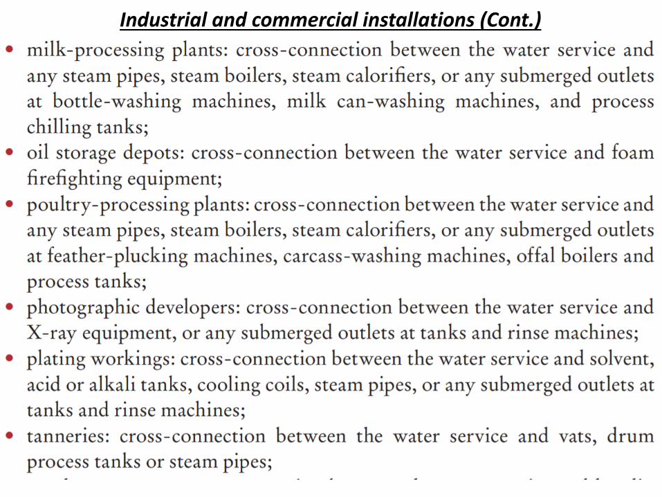
Industrial and commercial installations (Cont.)

38
Industrial and commercial installations (Cont.)
39
Industrial and commercial installations (Cont.)

40
Fixture unit calculations for multiple dwellings
A fixture unit (f/u) value is assigned to each type of fixture based on its rate of water consumption, on the length of time it is normally in use and on the average period between successive uses. Some examples of fixture unit values assigned to the most common fixtures are given in Table 3. When these are added their total gives a basis for determining the flow that may be expected in a water or drainage pipe to which two or more fixtures are connected. The total is then reduced by a factor, usually in the order of 0.6 to 0.7, but depending upon the margin of simultaneous use protection necessary under local conditions (Taylor & Wood 1982).

41
Fixture unit calculations for multiple dwellings
TABLE 3 FIXTURE UNIT VALUES FOR SOME COMMON PLUMBING FIXTURES

42
Fixture unit calculations for multiple dwellings
From Table 4 the size of the water pipes may be calculated using normal design principles (allowing for head loss, friction and other factors). Fixtures using both hot and cold water (such as in baths and sinks) should be assumed to take equal quantities of each for design purposes: a bath would be counted as one fixture unit on the cold water system, and one fixture unit on the hot water. Supply piping would be calculated accordingly, while the total figure of two fixture units would be used to design the drainage piping.
TABLE 4 PEAK WATER DEMAND OF PLUMBING FIXTURES

43
Fixture unit calculations for multiple dwellings From Table 5 the size of internal and external drains may be calculated according to the total number of fixtures discharging into each section, with the proviso that underground drains shall not be smaller than 100 millimeters (4 inches) diameter, and that no internal branch or drain of less than 80 millimeters (3 inches) diameter should carry the discharge of more than two water closets.
TABLE 5 MAXIMUM LOADS FOR HORIZONTAL FIXTURE BRANCHES AND BUILDING DRAINS OR SEWERS

44
Fixture unit calculations for multiple dwellings (Cont.)
An alternative to the fixture unit method for calculating flows is used in some
French-speaking countries. This method assigns individual flow values to each
fixture, multiplies the cumulative flow so obtained by a simultaneous use
factor obtained from a monogram and curve, and selects pipe sizes by
reference to precalculated tables.

Pingki Datta, Lecturer, Department of Civil Engineering, KUET.
45