Embed Size (px)
Citation preview
Department of Mechanical Engineering Khulna University of Engineering & Technology
Khulna-9203
Supervised ByMd. Rasedul IslamLecturerDepartment of Mechanical EngineeringKhulna University of Engineering & Technology (KUET)Khulna -9203, Bangladesh.
Submitted ByMOSTAQUEEM-INTESHAR (1205057)AMITAV ROY (1205058)K.M.MOHIUDDIN ABEER (1205060)
DESIGN AND CONSTRUCTION OF SPUR GEAR
OUTLINE 1.0 INTRODUCTION
2.0 OBJECTIVES
3.0 APPLICATION
4.0 SELECTION OF MATERIAL
5.0 PROBLEM
6.0 SOLUTION
7.0 CAD DESIGN
Department of Mechanical Engineering, KUET
1.0 INTRODUCTION
A gear is a wheel with teeth that mesh together with other gears. Gears change the speed, torque and direction of rotating axles.
A spur gear is a gear having straight teeth cut on the rim parallel to the axis of rotation.
Department of Mechanical Engineering, KUET
2.0 OBJECTIVES:
1. Design analytically a spur gear.
2. CAD design of the spur gear.
3. Construction of the spur gear.
Department of Mechanical Engineering, KUET
3.0 APPLICATION:
Spur gears can be used to increase or decrease the torque, or power, of a given object. Spur gears are used to this effect in washing machines, blenders, clothes dryers, construction equipment, fuel pumps and mills.
2. Spur Gears For Speed
Spur gears are also used to increase or decrease the speed of an object. For example, they are used in mechanical clocks to adjust the relative speeds of the second, minute and hour hands. In hand-held eggbeaters, spur gears are used to increase the speed of it
Department of Mechanical Engineering, KUET
1. Spur Gears For Power
3.0 APPLICATION (cont’d):
Department of Mechanical Engineering, KUET
3. Spur Gears and Cars : Spur gears are not used in cars because of the loud noise they produce at high speeds. The noise comes from the sound made when the teeth of the gears collide. Spur gears are, however, used in aircraft engines, where they are superior to helical gears, and where noise is not an issue.
The gear material should have the following properties:
High tensile strength to prevent failure against static loads
High endurance strength to withstand dynamic loads
Low coefficient of friction
Good manufacturability
Generally cast iron, steel, brass and bronze are preferred for manufacturing metallic gears with cut teeth. Where smooth action is not important, cast iron gears with cut teeth may be employed. Commercially cut gears have a pitch line velocity of about 5 metre/second. For velocities larger than this, gear sets with non-metallic pinions as one member are used to eliminate vibration and noise. Non-metallic materials are made of various materials such as treated cotton pressed and moulded at high-pressure, synthetic resins of the phenol type and rawhide.
4.0 Selection of Material:
5.0 Problem: A pair of gears with 20 degree full-depth teeth are to
transmit 10 hp at 1750 rpm of the 3-in. pinion; velocity ratio desired is about 3.8; intermittent service. Use a strength reduction factor of about 1.4, with the load at the tip and teeth commercially cut. Determine the pitch, face width, and tooth numbers if the material is cast iron, class 20.
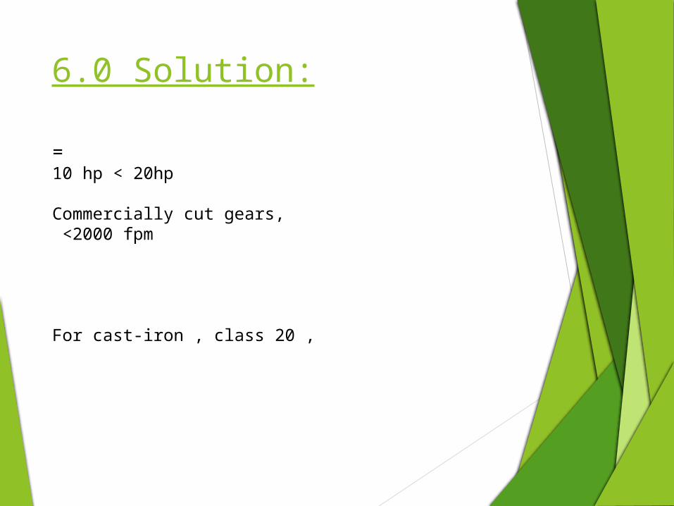
6.0 Solution:
= 10 hp < 20hp
Commercially cut gears, <2000 fpm
For cast-iron , class 20 ,

Solution (continued):Assume, Table AT 24 , Load at tip, Assume Y= 0.33
=
So, Use
Y = 0.289 =

b= 2
Summary of answers:
b= 2
Solution (continued):
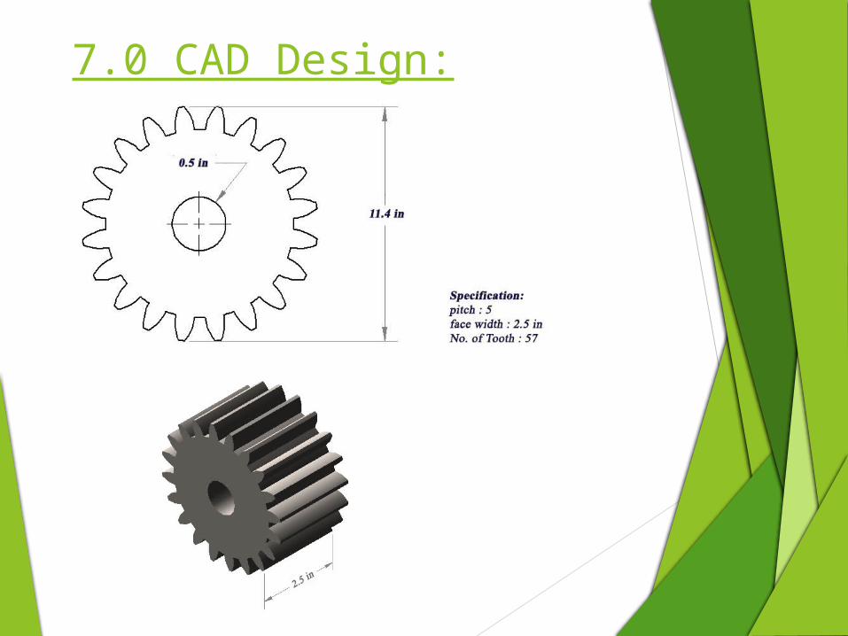
7.0 CAD Design:
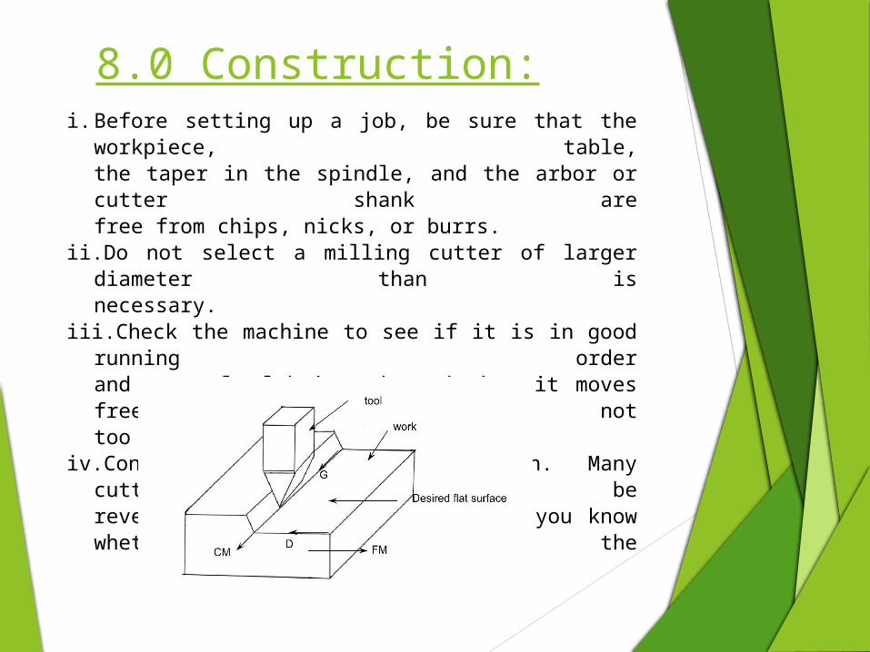
i. Before setting up a job, be sure that the workpiece, table,the taper in the spindle, and the arbor or cutter shank arefree from chips, nicks, or burrs.
ii. Do not select a milling cutter of larger diameter than isnecessary.
iii. Check the machine to see if it is in good running orderand properly lubricated, and that it moves freely, but nottoo freely in all directions.
iv. Consider direction of rotation. Many cutters can bereversed on the arbor, so be sure you know whether the
8.0 Construction:
v. Spindle is to rotate clockwise or counterclockwise.vi. Feed the workpiece in a direction opposite the
rotation ofthe milling cutter (conventional milling).
vii. Do not change feeds or speeds while the milling machineis in operation.
viii.When using clamps to secure a workpiece, be sure thatthey are tight and that the piece is held so it will notspring or vibrate under cut.
ix. Use a recommended cutting oil liberally.x. Use good judgment and common sense in planning
everyjob, and profit from previous mistakes.
xi. Set up every job as close to the milling machine spindleas circumstances will permit.
8.0 Construction (continued):

THANK YOU