Embed Size (px)
DESCRIPTION
Learn to Program for Windows in C
Citation preview

DO-15-001
MSDN Learn to Program for Windows in C++
N.T.TOAN

1
Table of Contents
Learn to Program for Windows in C++ ......................................................................... 3
Introduction to Windows Programming in C++ ............................................................................ 5
Prepare Your Development Environment ........................................................................................................................ 6
Windows Coding Conventions ............................................................................................................................................. 8
Working with Strings .............................................................................................................................................................. 11
What Is a Window? ................................................................................................................................................................. 14
WinMain: The Application Entry Point ............................................................................................................................ 18
Module 1. Your First Windows Program ........................................................................................ 21
Creating a Window ................................................................................................................................................................. 24
Window Messages .................................................................................................................................................................. 28
Writing the Window Procedure ......................................................................................................................................... 32
Painting the Window .............................................................................................................................................................. 35
Closing the Window ............................................................................................................................................................... 39
Managing Application State ................................................................................................................................................ 41
Module 2. Using COM in Your Windows Program .................................................................... 49
What Is a COM Interface? ..................................................................................................................................................... 50
Initializing the COM Library ................................................................................................................................................. 54
Error Codes in COM ................................................................................................................................................................ 56
Creating an Object in COM ................................................................................................................................................. 58
Example: The Open Dialog Box .......................................................................................................................................... 62
Managing the Lifetime of an Object ................................................................................................................................ 65
Asking an Object for an Interface ..................................................................................................................................... 70
Memory Allocation in COM ................................................................................................................................................. 72
COM Coding Practices ........................................................................................................................................................... 73
Error Handling in COM .......................................................................................................................................................... 79
Module 3. Windows Graphics ............................................................................................................ 87
Overview of the Windows Graphics Architecture ....................................................................................................... 88
The Desktop Window Manager ......................................................................................................................................... 91
Retained Mode Versus Immediate Mode ...................................................................................................................... 93
Your First Direct2D Program ............................................................................................................................................... 95
Render Targets, Devices, and Resources ..................................................................................................................... 100
Drawing with Direct2D ....................................................................................................................................................... 104

2
DPI and Device-Independent Pixels .............................................................................................................................. 108
Using Color in Direct2D ..................................................................................................................................................... 114
Applying Transforms in Direct2D ................................................................................................................................... 119
Appendix: Matrix Transforms ........................................................................................................................................... 125
Module 4. User Input .......................................................................................................................... 137
Mouse Input ............................................................................................................................................................................ 138
Responding to Mouse Clicks ............................................................................................................................................ 139
Mouse Movement ................................................................................................................................................................ 143
Miscellaneous Mouse Operations .................................................................................................................................. 149
Keyboard Input ...................................................................................................................................................................... 154
Accelerator Tables ................................................................................................................................................................ 160
Setting the Cursor Image................................................................................................................................................... 164
User Input: Extended Example ......................................................................................................................................... 166

3
Learn to Program for Windows in C++
Welcome to the series Learn to Program for Windows in C++. The aim of this series is to teach you how to
write a Windows program in C++.
In the first module, you'll learn step-by-step how to create and show a window. Later modules will
introduce the Component Object Model (COM), graphics and text, and user input.
For this series, it is assumed that you have a good working knowledge of C++ programming. No previous
experience with Windows programming is assumed. (If you are new to C++, you can find learning
material at the Visual C++ Developer Center.)
In This Section
Topic Description
Introduction to Windows
Programming in C++
This section describes some of the basic terminology and coding
conventions used in Windows programming.
Module 1. Your First Windows
Program
In this module, you will create a simple Windows program that shows
a blank window.
Module 2. Using COM in Your
Windows Program
This module introduces the Component Object Model (COM), which
underlies many of the modern Windows APIs.
Module 3. Windows Graphics This module introduces the Windows graphics architecture, with a
focus on Direct2D.
Module 4. User Input This module describes mouse and keyboard input.
Sample Code Contains links to download the sample code for this series.

4

5
Introduction to Windows Programming in C++
This section describes some of the basic terminology and coding conventions used in Windows
programming.
In This Section
Prepare Your Development Environment
Windows Coding Conventions
Working with Strings
What Is a Window?
WinMain: The Application Entry Point

6
Prepare Your Development Environment
Install the Windows SDK
To write a Windows program in C or C++, you must install the Microsoft Windows Software
Development Kit (SDK) or a development environment that includes the Windows SDK, such as Microsoft
Visual C++. The Windows SDK contains the headers and libraries necessary to compile and link your
application. The Windows SDK also contains command-line tools for building Windows applications,
including the Visual C++ compiler and linker. Although you can compile and build Windows programs
with the command-line tools, we recommend using a full-featured development environment such as
Microsoft Visual Studio. Visual C++ Express is a free downloadable edition of Visual C++ available at
http://go.microsoft.com/fwlink/?LinkId=181514.
Each release of the Windows SDK targets the latest version of Windows as well as several previous
versions. The release notes list the specific platforms that are supported, but unless you are maintaining
an application for a very old version of Windows, you should install the latest release of the Windows SDK.
You can download the latest Windows SDK from http://go.microsoft.com/fwlink/?LinkID=129787.
The Windows SDK supports development of both 32-bit and 64-bit applications. In fact, the Windows
APIs are designed so that the same code can compile for 32-bit or 64-bit without changes.
Note The Windows SDK does not support hardware driver development, and this series will not discuss
driver development. For information about writing a hardware driver, see Getting Started with Windows
Drivers.
Set Include and Library Paths
After you install the Windows SDK, make sure that your development environment points to the Include
and Lib folders, which contain the header and library files.
For Visual Studio, the Windows SDK includes a Visual Studio Configuration Tool. This tool updates Visual
Studio to use the Windows SDK header and library paths. For more information about this tool, see the
Windows SDK release notes (http://go.microsoft.com/fwlink/?LinkId=182068). Alternatively, you can add
the paths from Visual Studio. For more information, consult the Visual Studio help documentation.

7
A screen shot of the Visual Studio Configuration Tool
If you are interested in using Visual C++ 2010 Express, you can find more detailed setup instructions in
Chapter 2 of the "Hilo" project, Setting up the Hilo Development Environment.

8
Windows Coding Conventions
If you are new to Windows programming, it can be disconcerting when you first see a Windows program.
The code is filled with strange type definitions like DWORD_PTR and LPRECT, and variables have names
like hWnd and pwsz (called Hungarian notation). It's worth taking a moment to learn some of the
Windows coding conventions.
The vast majority of Windows APIs consist of either functions or Component Object Model (COM)
interfaces. Very few Windows APIs are provided as C++ classes. (A notable exception is GDI+, one of the
2-D graphics APIs.)
Typedefs
The Windows headers contain a lot of typedefs. Many of these are defined in the header file WinDef.h.
Here are some that you will encounter often.
Integer types
Data type Size Signed?
BYTE 8 bits Unsigned
DWORD 32 bits Unsigned
INT32 32 bits Signed
INT64 64 bits Signed
LONG 32 bits Signed
LONGLONG 64 bits Signed
UINT32 32 bits Unsigned
UINT64 64 bits Unsigned
ULONG 32 bits Unsigned
ULONGLONG 64 bits Unsigned
WORD 16 bits Unsigned

9
As you can see, there is a certain amount of redundancy in these typedefs. Some of this overlap is simply
due to the history of the Windows APIs. The types listed here have fixed size, and the sizes are the same in
both 32-bit and 64-applications. For example, the DWORD type is always 32 bits wide.
Boolean Type
BOOL is a typedef for an integer value that is used in a Boolean context. The header file WinDef.h also
defines two values for use with BOOL.
#define FALSE 0
#define TRUE 1
Despite this definition of TRUE, however, most functions that return a BOOL type can return any non-zero
value to indicate Boolean truth. Therefore, you should always write this:
// Right way.
BOOL result = SomeFunctionThatReturnsBoolean();
if (result)
{
...
}
and not this:
// Wrong!
if (result == TRUE)
{
...
}
Be aware that BOOL is an integer type and is not interchangeable with the C++ bool type.
Pointer Types
Windows defines many data types of the form pointer-to-X. These usually have the prefix P- or LP- in the
name. For example, LPRECT is a pointer to a RECT, where RECT is a structure that describes a rectangle.
The following variable declarations are equivalent.
RECT* rect; // Pointer to a RECT structure.
LPRECT rect; // The same
PRECT rect; // Also the same.

10
Historically, P stands for "pointer" and LP stands for "long pointer". Long pointers (also called far pointers)
are a holdover from 16-bit Windows, when they were needed to address memory ranges outside the
current segment. The LP prefix was preserved to make it easier to port 16-bit code to 32-bit Windows.
Today there is no distinction — a pointer is a pointer.
Pointer Precision Types
The following data types are always the size of a pointer — that is, 32 bits wide in 32-bit applications, and
64 bits wide in 64-bit applications. The size is determined at compile time. When a 32-bit application runs
on 64-bit Windows, these data types are still 4 bytes wide. (A 64-bit application cannot run on 32-bit
Windows, so the reverse situation does not occur.)
DWORD_PTR
INT_PTR
LONG_PTR
ULONG_PTR
UINT_PTR
These types are used in situations where an integer might be cast to a pointer. They are also used to
define variables for pointer arithmetic and to define loop counters that iterate over the full range of bytes
in memory buffers. More generally, they appear in places where an existing 32-bit value was expanded to
64 bits on 64-bit Windows.
Hungarian Notation
Hungarian notation is the practice of adding prefixes to the names of variables, to give additional
information about the variable. (The notation's inventor, Charles Simonyi, was Hungarian, hence its name).
In its original form, Hungarian notation gives semantic information about a variable, telling you the
intended use. For example, i means an index, cb means a size in bytes ("count of bytes"), and rw and col
mean row and column numbers. These prefixes are designed to avoid the accidental use of a variable in
the wrong context. For example, if you saw the expression rwPosition + cbTable, you would know that a
row number is being added to a size, which is almost certainly a bug in the code
A more common form of Hungarian notation uses prefixes to give type information — for example, dw for
DWORD and w for WORD.
If you search the Web for "Hungarian notation," you will find a lot of opinions about whether Hungarian
notation is good or bad. Some programmers have an intense dislike for Hungarian notation. Others find it
helpful. Regardless, many of the code examples on MSDN use Hungarian notation, but you don't need to
memorize the prefixes to understand the code.

11
Working with Strings
Windows natively supports Unicode strings for UI elements, file names, and so forth. Unicode is the
preferred character encoding, because it supports all character sets and languages. Windows represents
Unicode characters using UTF-16 encoding, in which each character is encoded as a 16-bit value. UTF-16
characters are called wide characters, to distinguish them from 8-bit ANSI characters. The Visual C++
compiler supports the built-in data type wchar_t for wide characters. The header file WinNT.h also defines
the following typedef.
typedef wchar_t WCHAR;
You will see both versions in MSDN example code. To declare a wide-character literal or a wide-character
string literal, put L before the literal.
wchar_t a = L'a';
wchar_t *str = L"hello";
Here are some other string-related typedefs that you will see:
Typedef Definition
CHAR char
PSTR or LPSTR char*
PCSTR or LPCSTR const char*
PWSTR or LPWSTR wchar_t*
PCWSTR or LPCWSTR const wchar_t*
Unicode and ANSI Functions
When Microsoft introduced Unicode support to Windows, it eased the transition by providing two parallel
sets of APIs, one for ANSI strings and the other for Unicode strings. For example, there are two functions
to set the text of a window's title bar:
SetWindowTextA takes an ANSI string.
SetWindowTextW takes a Unicode string.
Internally, the ANSI version translates the string to Unicode. The Windows headers also define a macro
that resolves to the Unicode version when the preprocessor symbol UNICODE is defined or the ANSI
version otherwise.

12
#ifdef UNICODE
#define SetWindowText SetWindowTextW
#else
#define SetWindowText SetWindowTextA
#endif
In MSDN, the function is documented under the name SetWindowText, even though that is really the
macro name, not the actual function name.
New applications should always call the Unicode versions. Many world languages require Unicode. If you
use ANSI strings, it will be impossible to localize your application. The ANSI versions are also less efficient,
because the operating system must convert the ANSI strings to Unicode at run time. Depending on your
preference, you can call the Unicode functions explicitly, such as SetWindowTextW, or use the macros.
The example code on MSDN typically calls the macros, but the two forms are exactly equivalent. Most
newer APIs in Windows have just a Unicode version, with no corresponding ANSI version.
TCHARs
Back when applications needed to support both Windows NT as well as Windows 95, Windows 98, and
Windows Me, it was useful to compile the same code for either ANSI or Unicode strings, depending on
the target platform. To this end, the Windows SDK provides macros that map strings to Unicode or ANSI,
depending on the platform.
Macro Unicode ANSI
TCHAR wchar_t char
TEXT("x") L"x" "x"
For example, the following code:
SetWindowText(TEXT("My Application"));
resolves to one of the following:
SetWindowTextW(L"My Application"); // Unicode function with wide-character
string.
SetWindowTextA("My Application"); // ANSI function.
13
The TEXT and TCHAR macros are less useful today, because all applications should use Unicode.
However, you might see them in older code and in some of the MSDN code examples.
The headers for the Microsoft C run-time libraries define a similar set of macros. For example, _tcslen
resolves to strlen if _UNICODE is undefined; otherwise it resolves to wcslen, which is the wide-character
version of strlen.
#ifdef _UNICODE
#define _tcslen wcslen
#else
#define _tcslen strlen
#endif
Be careful: Some headers use the preprocessor symbol UNICODE, others use _UNICODE with an
underscore prefix. Always define both symbols. Visual C++ sets them both by default when you create a
new project.

14
What Is a Window?
What Is a Window?
Obviously, windows are central to Windows. They are so important that they named the operating system
after them. But what is a window? When you think of a window, you probably think of something like this:
Screen shot of an application window
This type of window is called an application window or main window. It typically has a frame with a title
bar, Minimize and Maximize buttons, and other standard UI elements. The frame is called the non-client
area of the window, so called because the operating system manages that portion of the window. The
area within the frame is the client area. This is the part of the window that your program manages.
Here is another type of window:
Screen shot of a control window
If you are new to Windows programming, it may surprise you that UI controls, such as buttons and edit
boxes, are themselves windows. The major difference between a UI control and an application window is
that a control does not exist by itself. Instead, the control is positioned relative to the application window.
When you drag the application window, the control moves with it, as you would expect. Also, the control

15
and the application window can communicate with each other. (For example, the application window
receives click notifications from a button.)
Therefore, when you think window, do not simply think application window. Instead, think of a window as
a programming construct that:
Occupies a certain portion of the screen.
May or may not be visible at a given moment.
Knows how to draw itself.
Responds to events from the user or the operating system.
Parent Windows and Owner Windows
In the case of a UI control, the control window is said to be the child of the application window. The
application window is the parent of the control window. The parent window provides the coordinate
system used for positioning a child window. Having a parent window affects aspects of a window's
appearance; for example, a child window is clipped so that no part of the child window can appear
outside the borders of its parent window.
Another relationship is the relation between an application window and a modal dialog window. When an
application displays a modal dialog, the application window is the owner window, and the dialog is an
owned window. An owned window always appears in front of its owner window. It is hidden when the
owner is minimized, and is destroyed at the same time as the owner.
The following image shows an application that displays a dialog box with two buttons:
Screen shot of an application with a dialog box

16
The application window owns the dialog window, and the dialog window is the parent of both button
windows. The following diagram shows these relations:
Illustration showing parent/child and owner/owned relations
Window Handles
Windows are objects — they have both code and data — but they are not C++ classes. Instead, a
program references a window by using a value called a handle. A handle is an opaque type. Essentially, it
is just a number that the operating system uses to identify an object. You can picture Windows as having
a big table of all the windows that have been created. It uses this table to look up windows by their
handles. (Whether that's exactly how it works internally is not important.) The data type for window
handles is HWND, which is usually pronounced "aitch-wind." Window handles are returned by the
functions that create windows: CreateWindow and CreateWindowEx.
To perform an operation on a window, you will typically call some function that takes an HWND value as
a parameter. For example, to reposition a window on the screen, call the MoveWindow function:

17
BOOL MoveWindow(HWND hWnd, int X, int Y, int nWidth, int nHeight, BOOL
bRepaint);
The first parameter is the handle to the window that you want to move. The other parameters specify the
new location of the window and whether the window should be redrawn.
Keep in mind that handles are not pointers. If hwnd is a variable that contains a handle, attempting to
dereference the handle by writing *hwnd is an error.
Screen and Window Coordinates
Coordinates are measured in device-independent pixels. We'll have more to say about the device
independent part of device-independent pixels when we discuss graphics.
Depending on your task, you might measure coordinates relative to the screen, relative to a window
(including the frame), or relative to the client area of a window. For example, you would position a
window on the screen using screen coordinates, but you would draw inside a window using client
coordinates. In each case, the origin (0, 0) is always the top-left corner of the region.

18
Illustration showing screen, window, and client coordinates
WinMain: The Application Entry Point
Every Windows program includes an entry-point function that is named either WinMain or wWinMain.
Here is the signature for wWinMain.
int WINAPI wWinMain(HINSTANCE hInstance, HINSTANCE hPrevInstance, PWSTR
pCmdLine, int nCmdShow);
The four parameters are:
hInstance is something called a "handle to an instance" or "handle to a module." The operating
system uses this value to identify the executable (EXE) when it is loaded in memory. The instance
handle is needed for certain Windows functions — for example, to load icons or bitmaps.
hPrevInstance has no meaning. It was used in 16-bit Windows, but is now always zero.
pCmdLine contains the command-line arguments as a Unicode string.

19
nCmdShow is a flag that says whether the main application window will be minimized, maximized,
or shown normally.
The function returns an int value. The return value is not used by the operating system, but you can use
the return value to convey a status code to some other program that you write.
WINAPI is the calling convention. A calling convention defines how a function receives parameters from
the caller. For example, it defines the order that parameters appear on the stack. Just make sure to declare
your wWinMain function as shown.
The WinMain function is identical to wWinMain, except the command-line arguments are passed as an
ANSI string. The Unicode version is preferred. You can use the ANSI WinMain function even if you
compile your program as Unicode. To get a Unicode copy of the command-line arguments, call the
GetCommandLine function. This function returns all of the arguments in a single string. If you want the
arguments as an argv-style array, pass this string to CommandLineToArgvW.
How does the compiler know to invoke wWinMain instead of the standard main function? What actually
happens is that the Microsoft C runtime library (CRT) provides an implementation of main that calls either
WinMain or wWinMain.
Note The CRT does some additional work inside main. For example, any static initializers are called
before wWinMain. Although you can tell the linker to use a different entry-point function, use the default
if you link to the CRT. Otherwise, the CRT initialization code will be skipped, with unpredictable results.
(For example, global objects will not be initialized correctly.)
Here is an empty WinMain function.
INT WinMain(HINSTANCE hInstance, HINSTANCE hPrevInstance,
PSTR lpCmdLine, INT nCmdShow)
{
return 0;
}
Now that you have the entry point and understand some of the basic terminology and coding
conventions, you are ready to create a complete Window program.

20

21
Module 1. Your First Windows Program
In this module, we will write a minimal Windows program. All it does is create and show a blank window.
This first program contains about 50 lines of code, not counting blank lines and comments. It will be our
starting point; later we'll add graphics, text, user input, and other features.
Screen shot of the example program
Here is the complete code for the program:
#ifndef UNICODE
#define UNICODE
#endif
#include <windows.h>
LRESULT CALLBACK WindowProc(HWND hwnd, UINT uMsg, WPARAM wParam, LPARAM
lParam);
int WINAPI wWinMain(HINSTANCE hInstance, HINSTANCE, PWSTR pCmdLine, int
nCmdShow)
{
// Register the window class.
const wchar_t CLASS_NAME[] = L"Sample Window Class";
WNDCLASS wc = { };

22
wc.lpfnWndProc = WindowProc;
wc.hInstance = hInstance;
wc.lpszClassName = CLASS_NAME;
RegisterClass(&wc);
// Create the window.
HWND hwnd = CreateWindowEx(
0, // Optional window styles.
CLASS_NAME, // Window class
L"Learn to Program Windows", // Window text
WS_OVERLAPPEDWINDOW, // Window style
// Size and position
CW_USEDEFAULT, CW_USEDEFAULT, CW_USEDEFAULT, CW_USEDEFAULT,
NULL, // Parent window
NULL, // Menu
hInstance, // Instance handle
NULL // Additional application data
);
if (hwnd == NULL)
{
return 0;
}
ShowWindow(hwnd, nCmdShow);
// Run the message loop.
MSG msg = { };
while (GetMessage(&msg, NULL, 0, 0))
{
TranslateMessage(&msg);
DispatchMessage(&msg);
}
return 0;
}
LRESULT CALLBACK WindowProc(HWND hwnd, UINT uMsg, WPARAM wParam, LPARAM
lParam)
{
switch (uMsg)
{
case WM_DESTROY:
PostQuitMessage(0);
return 0;

23
case WM_PAINT:
{
PAINTSTRUCT ps;
HDC hdc = BeginPaint(hwnd, &ps);
FillRect(hdc, &ps.rcPaint, (HBRUSH) (COLOR_WINDOW+1));
EndPaint(hwnd, &ps);
}
return 0;
}
return DefWindowProc(hwnd, uMsg, wParam, lParam);
}
You can download the complete Visual Studio project from Windows Hello World Sample.
It may be useful to give a brief outline of what this code does. Later topics will examine the code in detail.
1. wWinMain is the program entry point. When the program starts, it registers some information
about the behavior of the application window. One of the most important items is the address of
a function, named WindowProc in this example. This function defines the behavior of the
window—its appearance, how it interacts with the user, and so forth.
2. Next, the program creates the window and receives a handle that uniquely identifies the window.
3. If the window is created successfully, the program enters a while loop. The program remains in
this loop until the user closes the window and exits the application.
Notice that the progam does not explicitly call the WindowProc function, even though we said this is
where most of the application logic is defined. Windows communicates with your program by passing it a
series of messages. The code inside the while loop drives this process. Each time the program calls the
DispatchMessage function, it indirectly causes Windows to invoke the WindowProc function, once for
each message.
In This Section
Creating a Window
Window Messages
Writing the Window Procedure
Painting the Window
Closing the Window
Managing Application State

24
Creating a Window
Window Classes
A window class defines a set of behaviors that several windows might have in common. For example, in a
group of buttons, each button has a similar behavior when the user clicks the button. Of course, buttons
are not completely identical; each button displays its own text string and has its own screen coordinates.
Data that is unique for each window is called instance data.
Every window must be associated with a window class, even if your program only ever creates one
instance of that class. It is important to understand that a window class is not a "class" in the C++ sense.
Rather, it is a data structure used internally by the operating system. Window classes are registered with
the system at run time. To register a new window class, start by filling in a WNDCLASS structure:
// Register the window class.
const wchar_t CLASS_NAME[] = L"Sample Window Class";
WNDCLASS wc = { };
wc.lpfnWndProc = WindowProc;
wc.hInstance = hInstance;
wc.lpszClassName = CLASS_NAME;
You must set the following structure members:
lpfnWndProc is a pointer to an application-defined function called the window procedure or
"window proc." The window procedure defines most of the behavior of the window. We'll examine
the window procedure in detail later. For now, just treat this as a forward reference.
hInstance is the handle to the application instance. Get this value from the hInstance parameter of
wWinMain.
lpszClassName is a string that identifies the window class.
Class names are local to the current process, so the name only needs to be unique within the process.
However, the standard Windows controls also have classes. If you use any of those controls, you must pick
class names that do not conflict with the control class names. For example, the window class for the
button control is named "Button".
The WNDCLASS structure has other members not shown here. You can set them to zero, as shown in this
example, or fill them in. The MSDN documentation describes the structure in detail.
Next, pass the address of the WNDCLASS structure to the RegisterClass function. This function registers
the window class with the operating system.

25
RegisterClass(&wc);
Creating the Window
To create a new instance of a window, call the CreateWindowEx function:
HWND hwnd = CreateWindowEx(
0, // Optional window styles.
CLASS_NAME, // Window class
L"Learn to Program Windows", // Window text
WS_OVERLAPPEDWINDOW, // Window style
// Size and position
CW_USEDEFAULT, CW_USEDEFAULT, CW_USEDEFAULT, CW_USEDEFAULT,
NULL, // Parent window
NULL, // Menu
hInstance, // Instance handle
NULL // Additional application data
);
if (hwnd == NULL)
{
return 0;
}
You can read detailed parameter descriptions on MSDN, but here is a quick summary:
The first parameter lets you specify some optional behaviors for the window (for example,
transparent windows). Set this parameter to zero for the default behaviors.
CLASS_NAME is the name of the window class. This defines the type of window you are creating.
The window text is used in different ways by different types of windows. If the window has a title
bar, the text is displayed in the title bar.
The window style is a set of flags that define some of the look and feel of a window. The constant
WS_OVERLAPPEDWINDOW is actually several flags combined with a bitwise OR. Together these
flags give the window a title bar, a border, a system menu, and Minimize and Maximize buttons.
This set of flags is the most common style for a top-level application window.
For position and size, the constant CW_USEDEFAULT means to use default values.
The next parameter sets a parent window or owner window for the new window. Set the parent if
you are creating a child window. For a top-level window, set this to NULL.

26
For an application window, the next parameter defines the menu for the window. This example
does not use a menu, so the value is NULL.
hInstance is the instance handle, described previously. (See WinMain: The Application Entry
Point.)
The last parameter is a pointer to arbitrary data of type void*. You can use this value to pass a
data structure to your window procedure. We'll show one possible way to use this parameter in
the section Managing Application State.
CreateWindowEx returns a handle to the new window, or zero if the function fails. To show the
window—that is, make the window visible —pass the window handle to the ShowWindow function:
ShowWindow(hwnd, nCmdShow);
The hwnd parameter is the window handle returned by CreateWindowEx. The nCmdShow parameter can
be used to minimize or maximize a window. The operating system passes this value to the program
through the wWinMain function.
Here is the complete code to create the window. Remember that WindowProc is still just a forward
declaration of a function.
// Register the window class.
const wchar_t CLASS_NAME[] = L"Sample Window Class";
WNDCLASS wc = { };
wc.lpfnWndProc = WindowProc;
wc.hInstance = hInstance;
wc.lpszClassName = CLASS_NAME;
RegisterClass(&wc);
// Create the window.
HWND hwnd = CreateWindowEx(
0, // Optional window styles.
CLASS_NAME, // Window class
L"Learn to Program Windows", // Window text
WS_OVERLAPPEDWINDOW, // Window style
// Size and position
CW_USEDEFAULT, CW_USEDEFAULT, CW_USEDEFAULT, CW_USEDEFAULT,
27
NULL, // Parent window
NULL, // Menu
hInstance, // Instance handle
NULL // Additional application data
);
if (hwnd == NULL)
{
return 0;
}
ShowWindow(hwnd, nCmdShow);
Congratulations, you've created a window! Right now, the window does not contain any content or
interact with the user. In a real GUI application, the window would respond to events from the user and
the operating system. The next section describes how window messages provide this sort of interactivity.

28
Window Messages
A GUI application must respond to events from the user and from the operating system.
Events from the user include all of the ways that someone can interact with your program:
mouse clicks, key strokes, touch-screen gestures, and so forth.
Events from the operating system include anything "outside" of the program that can affect
how the program behaves. For example, the user might plug in a new hardware device, or
Windows might enter a lower-power state (sleep or hibernate).
These events can occur at any time while the program is running, in almost any order. How do you
structure a program whose flow of execution cannot be predicted in advance?
To solve this problem, Windows uses a message-passing model. The operating system communicates
with your application window by passing messages to it. A message is simply a numeric code that
designates a particular event. For example, if the user presses the left mouse button, the window receives
a message with the following message code.
#define WM_LBUTTONDOWN 0x0201
Some messages have data associated with them. For example, the WM_LBUTTONDOWN message
includes the x-coordinate and y-coordinate of the mouse cursor.
To pass a message to a window, the operating system calls the window procedure registered for that
window. (And now you know what the window procedure is for.)
The Message Loop
An application will receive thousands of messages while it runs. (Consider that every keystroke and
mouse-button click generates a message.) Furthermore, an application can have several windows, each
with its own window procedure. How does the program receive all of these messages and deliver them to
the right window procedure? The application needs a loop to get the messages and distpatch them to the
correct windows.
For each thread that creates a window, the operating system creates a queue for window messages. This
queue holds messages for all of the windows that are created on that thread. The queue itself is hidden
from your progam. You can't manipulate the queue directly, but you can pull a message from the queue
by calling the GetMessage function.
MSG msg;
GetMessage(&msg, NULL, 0, 0);

29
This function removes the first message from the head of the queue. If the queue is empty, the function
blocks until another message is queued. The fact that GetMessage blocks will not make your program
unresponsive. If there are no messages, there is nothing for the program to do. If you need to perform
background processing, you can create additional threads that continue to run while GetMessage waits
for another message. (See Avoiding Bottlenecks in Your Window Procedure.)
The first parameter of GetMessage is the address of a MSG structure. If the function succeeds, it fills in
the MSG structure with information about the message, including the target window and the message
code. The other three parameters give you the ability to filter which messages you get from the queue. In
almost all cases, you will set these parameters to zero.
Although the MSG structure contains information about the message, you will almost never examine this
structure directly. Instead, you will pass it directly to two other functions.
TranslateMessage(&msg);
DispatchMessage(&msg);
The TranslateMessage function is related to keyboard input; it translates keystrokes (key down, key up)
into characters. You don't really need to know how this function works; just remember to call it right
before DispatchMessage. The link to the MSDN documentation will give you more information, if you're
curious.
The DispatchMessage function tells the operating system to call the window procedure of the window
that is the target of the message. In other words, the operating system looks up the window handle in its
table of windows, finds the function pointer associated with the window, and invokes the function.
For example, suppose the user presses the left mouse button. This causes a chain of events:
1. The operating system places a WM_LBUTTONDOWN message on the message queue.
2. Your program calls the GetMessage function.
3. GetMessage pulls the WM_LBUTTONDOWN message from the queue and fills in the MSG
structure.
4. Your program calls the TranslateMessage and DispatchMessage functions.
5. Inside DispatchMessage, the operating system calls your window procedure.
6. Your window procedure can either respond to the message or ignore it.
When the window procedure returns, it returns back to DispatchMessage, which returns to the message
loop for the next message. As long as your program is running, messages will continue to arrive on the
queue. Therefore, you need a loop that continually pulls messages from the queue and dispatches them.
You can think of the loop as doing the following:
// WARNING: Don't actually write your loop this way.

30
while (1)
{
GetMessage(&msg, NULL, 0, 0);
TranslateMessage(&msg);
DispatchMessage(&msg);
}
As written, of course, this loop would never end. That's where the return value for the GetMessage
function comes in. Normally, GetMessage returns a non-zero value. Whenever you want to quit the
application and break out of the message loop, simply call the PostQuitMessage function.
PostQuitMessage(0);
The PostQuitMessage function puts a WM_QUIT message on the message queue. WM_QUIT is a special
message: It causes GetMessage to return zero, signaling the end of the message loop. Here is the revised
message loop.
// Correct.
MSG msg = { };
while (GetMessage(&msg, NULL, 0, 0))
{
TranslateMessage(&msg);
DispatchMessage(&msg);
}
As long as GetMessage returns a non-zero value, the expression in the while loop evaluates to true. After
you call PostQuitMessage, the expression becomes false and the program breaks out of the loop. (One
interesting consequence of this behavior is that your window procedure never receives a WM_QUIT
message, so do not need a case statement for this message in your window procedure.)
The next obvious question is: When should you call PostQuitMessage? We'll return to this question in the
topic Closing the Window, but first we need to write our window procedure.
Posted Messages versus Sent Messages
The previous section talked about messages going onto a queue. In some situations, the operating
system will call a window procedure directly, bypassing the queue.

31
The terminology for this distinction can be confusing:
Posting a message means the message goes on the message queue, and is dispatched through
the message loop (GetMessage and DispatchMessage).
Sending a message means the message skips the queue, and the operating system calls the
window procedure directly.
For now, the distinction is not very important. The window procedure handles all messages, but some
messages bypass the queue and go directly to your window procedure. However, it can make a difference
if your application communicates between windows. You can find a more thorough discussion of this
issue in the topic About Messages and Message Queues.
32
Writing the Window Procedure
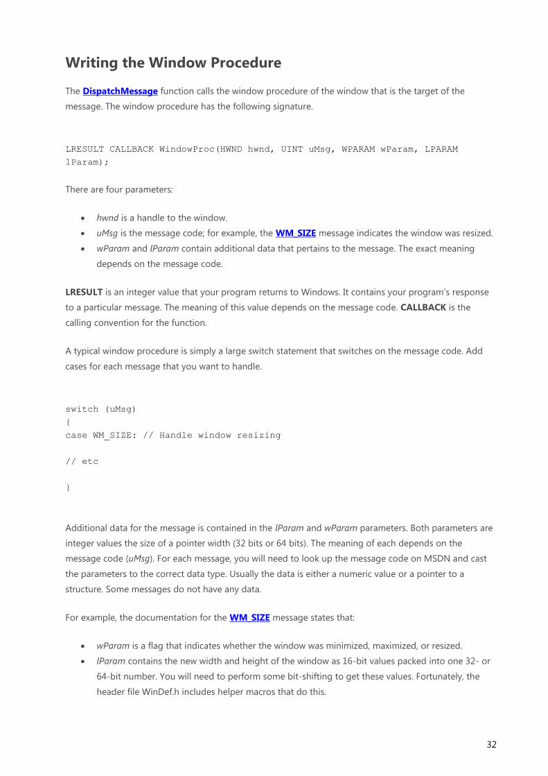
The DispatchMessage function calls the window procedure of the window that is the target of the
message. The window procedure has the following signature.
LRESULT CALLBACK WindowProc(HWND hwnd, UINT uMsg, WPARAM wParam, LPARAM
lParam);
There are four parameters:
hwnd is a handle to the window.
uMsg is the message code; for example, the WM_SIZE message indicates the window was resized.
wParam and lParam contain additional data that pertains to the message. The exact meaning
depends on the message code.
LRESULT is an integer value that your program returns to Windows. It contains your program's response
to a particular message. The meaning of this value depends on the message code. CALLBACK is the
calling convention for the function.
A typical window procedure is simply a large switch statement that switches on the message code. Add
cases for each message that you want to handle.
switch (uMsg)
{
case WM_SIZE: // Handle window resizing
// etc
}
Additional data for the message is contained in the lParam and wParam parameters. Both parameters are
integer values the size of a pointer width (32 bits or 64 bits). The meaning of each depends on the
message code (uMsg). For each message, you will need to look up the message code on MSDN and cast
the parameters to the correct data type. Usually the data is either a numeric value or a pointer to a
structure. Some messages do not have any data.
For example, the documentation for the WM_SIZE message states that:
wParam is a flag that indicates whether the window was minimized, maximized, or resized.
lParam contains the new width and height of the window as 16-bit values packed into one 32- or
64-bit number. You will need to perform some bit-shifting to get these values. Fortunately, the
header file WinDef.h includes helper macros that do this.

33
A typical window procedure handles dozens of messages, so it can grow quite long. One way to make
your code more modular is to put the logic for handling each message in a separate function. In the
window procedure, cast the wParam and lParam parameters to the correct data type, and pass those
values to the function. For example, to handle the WM_SIZE message, the window procedure would look
like this:
LRESULT CALLBACK WindowProc(HWND hwnd, UINT uMsg, WPARAM wParam, LPARAM
lParam)
{
switch (uMsg)
{
case WM_SIZE:
{
int width = LOWORD(lParam); // Macro to get the low-order word.
int height = HIWORD(lParam); // Macro to get the high-order word.
// Respond to the message:
OnSize(hwnd, (UINT)wParam, width, height);
}
break;
}
}
void OnSize(HWND hwnd, UINT flag, int width, int height);
{
// Handle resizing
}
The LOWORD and HIWORD macros get the 16-bit width and height values from lParam. (You can look
up these kinds of details in the MSDN documentation for each message code.) The window procedure
extracts the width and height, and then passes these values to the OnSize function.
Default Message Handling
If you don't handle a particular message in your window procedure, pass the message parameters directly
to the DefWindowProc function. This function performs the default action for the message, which varies
by message type.
return DefWindowProc(hwnd, uMsg, wParam, lParam);
34
Avoiding Bottlenecks in Your Window Procedure
While your window procedure executes, it blocks any other messages for windows created on the same
thread. Therefore, avoid lengthy processing inside your window procedure. For example, suppose your
program opens a TCP connection and waits indefinitely for the server to respond. If you do that inside the
window procedure, your UI will not respond until the request completes. During that time, the window
cannot process mouse or keyboard input, repaint itself, or even close.
Instead, you should move the work to another thread, using one of the multitasking facilities that are built
into Windows:
Create a new thread.
Use a thread pool.
Use asynchronous I/O calls.
Use asynchronous procedure calls.

35
Painting the Window
You've created your window. Now you want to show something inside it. In Windows terminology, this is
called painting the window. To mix metaphors, a window is a blank canvas, waiting for you to fill it.
Sometimes your program will initiate painting to update the appearance of the window. At other times,
the operating system will notify you that you must repaint a portion of the window. When this occurs, the
operating system sends the window a WM_PAINT message. The portion of the window that must be
painted is called the update region.
The first time a window is shown, the entire client area of the window must be painted. Therefore, you will
always receive at least one WM_PAINT message when you show a window.
Illustration showing the update region of a window
You are only responsible for painting the client area. The surrounding frame, including the title bar, is
automatically painted by the operating system. After you finish painting the client area, you clear the
update region, which tells the operating system that it does not need to send another WM_PAINT
message until something changes.
Now suppose the user moves another window so that it obscures a portion of your window. When the
obscured portion becomes visible again, that portion is added to the update region, and your window
receives another WM_PAINT message.
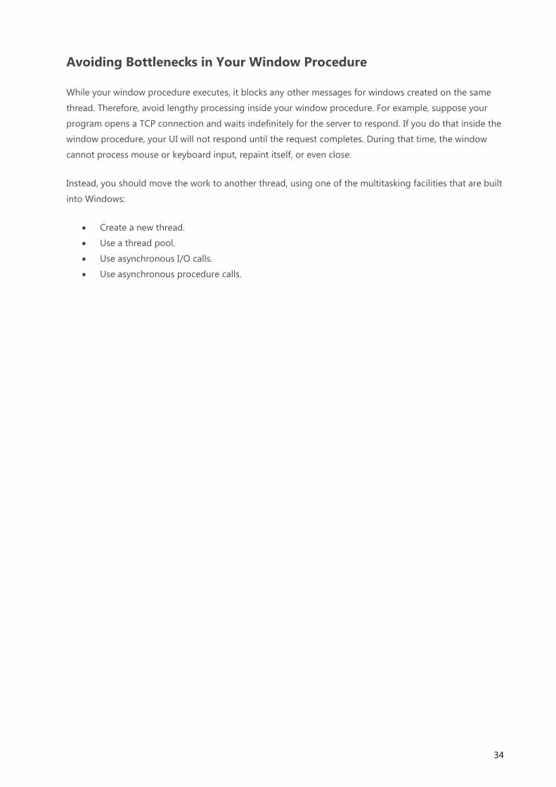
36
Illustration showing how the update region changes when two windows overlap
The update region also changes if the user stretches the window. In the following diagram, the user
stretches the window to the right. The newly exposed area on the right side of the window is added to the
update region:
Illustration showing how the update region changes when a window is resized
In our first example program, the painting routine is very simple. It just fills the entire client area with a
solid color. Still, this example is enough to demonstrate some of the important concepts.

37
switch (uMsg)
{
case WM_PAINT:
{
PAINTSTRUCT ps;
HDC hdc = BeginPaint(hwnd, &ps);
// All painting occurs here, between BeginPaint and EndPaint.
FillRect(hdc, &ps.rcPaint, (HBRUSH) (COLOR_WINDOW+1));
EndPaint(hwnd, &ps);
}
return 0;
}
Start the painting operation by calling the BeginPaint function. This function fills in the PAINTSTRUCT
structure with information on the repaint request. The current update region is given in the rcPaint
member of PAINTSTRUCT. This update region is defined relative to the client area:
Illustration showing the origin of the client area
In your painting code, you have two basic options:
Paint the entire client area, regardless of the size of the update region. Anything that falls outside
of the update region is clipped. That is, the operating system ignores it.
Optimize by painting just the portion of the window inside the update region.

38
If you always paint the entire client area, the code will be simpler. If you have complicated painting logic,
however, it can be more efficient to skip the areas outside of the update region.
The following line of code fills the update region with a single color, using the system-defined window
background color (COLOR_WINDOW). The actual color indicated by COLOR_WINDOW depends on the
user's current color scheme.
FillRect(hdc, &ps.rcPaint, (HBRUSH) (COLOR_WINDOW+1));
The details of FillRect are not important for this example, but the second parameter gives the coordinates
of the rectangle to fill. In this case, we pass in the entire update region (the rcPaint member of
PAINTSTRUCT). On the first WM_PAINT message, the entire client area needs to be painted, so rcPaint
will contain the entire client area. On subsequent WM_PAINT messages, rcPaint might contain a smaller
rectangle.
The FillRect function is part of the Graphics Device Interface (GDI), which has powered Windows graphics
for a very long time. In Windows 7, Microsoft introduced a new graphics engine, named Direct2D, which
supports high-performance graphics operations, such as hardware acceleration. Direct2D is also available
for Windows Vista through the Platform Update for Windows Vista and for Windows Server 2008
through the Platform Update for Windows Server 2008. (GDI is still fully supported.)
After you are done painting, call the EndPaint function. This function clears the update region, which
signals to Windows that the window has completed painting itself.

39
Closing the Window
When the user closes a window, that action triggers a sequence of window messages.
The user can close an application window by clicking the Close button, or by using a keyboard shortcut
such as ALT+F4. Any of these actions causes the window to receive a WM_CLOSE message. The
WM_CLOSE message gives you an opportunity to prompt the user before closing the window. If you
really do want to close the window, call the DestroyWindow function. Otherwise, simply return zero from
the WM_CLOSE message, and the operating system will ignore the message and not destroy the window.
Here is an example of how a program might handle WM_CLOSE.
case WM_CLOSE:
if (MessageBox(hwnd, L"Really quit?", L"My application", MB_OKCANCEL) ==
IDOK)
{
DestroyWindow(hwnd);
}
// Else: User canceled. Do nothing.
return 0;
In this example, the MessageBox function shows a modal dialog that contains OK and Cancel buttons. If
the user clicks OK, the program calls DestroyWindow. Otherwise, if the user clicks Cancel, the call to
DestroyWindow is skipped, and the window remains open. In either case, return zero to indicate that you
handled the message.
If you want to close the window without prompting the user, you could simply call DestroyWindow
without the call to MessageBox. However, there is a shortcut in this case. Recall that DefWindowProc
executes the default action for any window message. In the case of WM_CLOSE, DefWindowProc
automatically calls DestroyWindow. That means if you ignore the WM_CLOSE message in your switch
statement, the window is destroyed by default.
When a window is about to be destroyed, it receives a WM_DESTROY message. This message is sent after
the window is removed from the screen, but before the destruction occurs (in particular, before any child
windows are destroyed).
In your main application window, you will typically respond to WM_DESTROY by calling
PostQuitMessage.
case WM_DESTROY:
PostQuitMessage(0);
return 0;

40
We saw in the Window Messages section that PostQuitMessage puts a WM_QUIT message on the
message queue, causing the message loop to end.
Here is a flow chart showing the typical way to process WM_CLOSE and WM_DESTROY messages:
Flow chart showing how to handle WM_CLOSE and WM_DESTROY messages

41
Managing Application State
A window procedure is just a function that gets invoked for every message, so it is inherently stateless.
Therefore, you need a way to track the state of your application from one function call to the next.
The simplest approach is simply to put everything in global variables. This works well enough for small
programs, and many of the SDK samples use this approach. In a large program, however, it leads to a
proliferation of global variables. Also, you might have several windows, each with its own window
procedure. Keeping track of which window should access which variables becomes confusing and error-
prone.
The CreateWindowEx function provides a way to pass any data structure to a window. When this
function is called, it sends the following two messages to your window procedure:
WM_NCCREATE
WM_CREATE
These messages are sent in the order listed. (These are not the only two messages sent during
CreateWindowEx, but we can ignore the others for this discussion.)
The WM_NCCREATE and WM_CREATE message are sent before the window becomes visible. That makes
them a good place to initialize your UI—for example, to determine the initial layout of the window.
The last parameter of CreateWindowEx is a pointer of type void*. You can pass any pointer value that
you want in this parameter. When the window procedure handles the WM_NCCREATE or WM_CREATE
message, it can extract this value from the message data.
Let's see how you would use this parameter to pass application data to your window. First, define a class
or structure that holds state information.
// Define a structure to hold some state information.
struct StateInfo {
// ... (struct members not shown)
};
When you call CreateWindowEx, pass a pointer to this structure in the final void* parameter.
StateInfo *pState = new (std::nothrow) StateInfo;

42
if (pState == NULL)
{
return 0;
}
// Initialize the structure members (not shown).
HWND hwnd = CreateWindowEx(
0, // Optional window styles.
CLASS_NAME, // Window class
L"Learn to Program Windows", // Window text
WS_OVERLAPPEDWINDOW, // Window style
// Size and position
CW_USEDEFAULT, CW_USEDEFAULT, CW_USEDEFAULT, CW_USEDEFAULT,
NULL, // Parent window
NULL, // Menu
hInstance, // Instance handle
pState // Additional application data
);
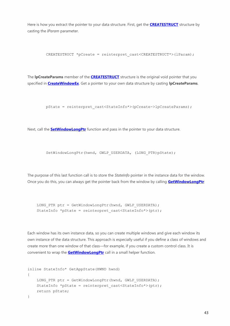
When you receive the WM_NCCREATE and WM_CREATE messages, the lParam parameter of each
message is a pointer to a CREATESTRUCT structure. The CREATESTRUCT structure, in turn, contains the
pointer that you passed into CreateWindowEx.
Diagram that shows the layout of the CREATESTRUCT structure
43
Here is how you extract the pointer to your data structure. First, get the CREATESTRUCT structure by
casting the lParam parameter.
CREATESTRUCT *pCreate = reinterpret_cast<CREATESTRUCT*>(lParam);
The lpCreateParams member of the CREATESTRUCT structure is the original void pointer that you
specified in CreateWindowEx. Get a pointer to your own data structure by casting lpCreateParams.
pState = reinterpret_cast<StateInfo*>(pCreate->lpCreateParams);
Next, call the SetWindowLongPtr function and pass in the pointer to your data structure.
SetWindowLongPtr(hwnd, GWLP_USERDATA, (LONG_PTR)pState);
The purpose of this last function call is to store the StateInfo pointer in the instance data for the window.
Once you do this, you can always get the pointer back from the window by calling GetWindowLongPtr:
LONG_PTR ptr = GetWindowLongPtr(hwnd, GWLP_USERDATA);
StateInfo *pState = reinterpret_cast<StateInfo*>(ptr);
Each window has its own instance data, so you can create multiple windows and give each window its
own instance of the data structure. This approach is especially useful if you define a class of windows and
create more than one window of that class—for example, if you create a custom control class. It is
convenient to wrap the GetWindowLongPtr call in a small helper function.
inline StateInfo* GetAppState(HWND hwnd)
{
LONG_PTR ptr = GetWindowLongPtr(hwnd, GWLP_USERDATA);
StateInfo *pState = reinterpret_cast<StateInfo*>(ptr);
return pState;
}

44
Now you can write your window procedure as follows.
LRESULT CALLBACK WindowProc(HWND hwnd, UINT uMsg, WPARAM wParam, LPARAM
lParam)
{
StateInfo *pState;
if (uMsg == WM_CREATE)
{
CREATESTRUCT *pCreate = reinterpret_cast<CREATESTRUCT*>(lParam);
pState = reinterpret_cast<StateInfo*>(pCreate->lpCreateParams);
SetWindowLongPtr(hwnd, GWLP_USERDATA, (LONG_PTR)pState);
}
else
{
pState = GetAppState(hwnd);
}
switch (uMsg)
{
// Remainder of the window procedure not shown ...
}
return TRUE;
}
An Object-Oriented Approach
We can extend this approach further. We have already defined a data structure to hold state information
about the window. It makes sense to provide this data structure with member functions (methods) that
operate on the data. This naturally leads to a design where the structure (or class) is responsible for all of
the operations on the window. The window procedure would then become part of the class.
In other words, we would like to go from this:
// pseudocode
LRESULT CALLBACK WindowProc(HWND hwnd, UINT uMsg, WPARAM wParam, LPARAM
lParam)
{
StateInfo *pState;

45
/* Get pState from the HWND. */
switch (uMsg)
{
case WM_SIZE:
HandleResize(pState, ...);
break;
case WM_PAINT:
HandlePaint(pState, ...);
break;
// And so forth.
}
}
To this:
// pseudocode
LRESULT MyWindow::WindowProc(UINT uMsg, WPARAM wParam, LPARAM lParam)
{
switch (uMsg)
{
case WM_SIZE:
this->HandleResize(...);
break;
case WM_PAINT:
this->HandlePaint(...);
break;
}
}
The only problem is how to hook up the MyWindow::WindowProc method. The RegisterClass function
expects the window procedure to be a function pointer. You can't pass a pointer to a (non-static) member
function in this context. However, you can pass a pointer to a static member function and then delegate
to the member function. Here is a class template that shows this approach:
template <class DERIVED_TYPE>
class BaseWindow
{
public:

46
static LRESULT CALLBACK WindowProc(HWND hwnd, UINT uMsg, WPARAM wParam,
LPARAM lParam)
{
DERIVED_TYPE *pThis = NULL;
if (uMsg == WM_NCCREATE)
{
CREATESTRUCT* pCreate = (CREATESTRUCT*)lParam;
pThis = (DERIVED_TYPE*)pCreate->lpCreateParams;
SetWindowLongPtr(hwnd, GWLP_USERDATA, (LONG_PTR)pThis);
pThis->m_hwnd = hwnd;
}
else
{
pThis = (DERIVED_TYPE*)GetWindowLongPtr(hwnd, GWLP_USERDATA);
}
if (pThis)
{
return pThis->HandleMessage(uMsg, wParam, lParam);
}
else
{
return DefWindowProc(hwnd, uMsg, wParam, lParam);
}
}
BaseWindow() : m_hwnd(NULL) { }
BOOL Create(
PCWSTR lpWindowName,
DWORD dwStyle,
DWORD dwExStyle = 0,
int x = CW_USEDEFAULT,
int y = CW_USEDEFAULT,
int nWidth = CW_USEDEFAULT,
int nHeight = CW_USEDEFAULT,
HWND hWndParent = 0,
HMENU hMenu = 0
)
{
WNDCLASS wc = {0};
wc.lpfnWndProc = DERIVED_TYPE::WindowProc;
wc.hInstance = GetModuleHandle(NULL);
wc.lpszClassName = ClassName();
RegisterClass(&wc);
m_hwnd = CreateWindowEx(
dwExStyle, ClassName(), lpWindowName, dwStyle, x, y,

47
nWidth, nHeight, hWndParent, hMenu, GetModuleHandle(NULL), this
);
return (m_hwnd ? TRUE : FALSE);
}
HWND Window() const { return m_hwnd; }
protected:
virtual PCWSTR ClassName() const = 0;
virtual LRESULT HandleMessage(UINT uMsg, WPARAM wParam, LPARAM lParam) =
0;
HWND m_hwnd;
};
The BaseWindow class is an abstract base class, from which specific window classes are derived. For
example, here is the declaration of a simple class derived from BaseWindow:
class MainWindow : public BaseWindow<MainWindow>
{
public:
PCWSTR ClassName() const { return L"Sample Window Class"; }
LRESULT HandleMessage(UINT uMsg, WPARAM wParam, LPARAM lParam);
};
To create the window, call BaseWindow::Create:
int WINAPI wWinMain(HINSTANCE hInstance, HINSTANCE, PWSTR pCmdLine, int
nCmdShow)
{
MainWindow win;
if (!win.Create(L"Learn to Program Windows", WS_OVERLAPPEDWINDOW))
{
return 0;
}
ShowWindow(win.Window(), nCmdShow);
// Run the message loop.

48
MSG msg = { };
while (GetMessage(&msg, NULL, 0, 0))
{
TranslateMessage(&msg);
DispatchMessage(&msg);
}
return 0;
}
The pure-virtual BaseWindow::HandleMessage method is used to implement the window procedure. For
example, the following implementation is equivalent to the window procedure shown at the start of
Module 1.
LRESULT MainWindow::HandleMessage(UINT uMsg, WPARAM wParam, LPARAM lParam)
{
switch (uMsg)
{
case WM_DESTROY:
PostQuitMessage(0);
return 0;
case WM_PAINT:
{
PAINTSTRUCT ps;
HDC hdc = BeginPaint(m_hwnd, &ps);
FillRect(hdc, &ps.rcPaint, (HBRUSH) (COLOR_WINDOW+1));
EndPaint(m_hwnd, &ps);
}
return 0;
default:
return DefWindowProc(m_hwnd, uMsg, wParam, lParam);
}
return TRUE;
}
Notice that the window handle is stored in a member variable (m_hwnd), so we do not need to pass it as a
parameter to HandleMessage.
Many of the existing Windows programming frameworks, such as Microsoft Foundation Classes (MFC)
and Active Template Library (ATL), use approaches that are basically similar to the one shown here. Of
course, a fully generalized framework such as MFC is more complex than this relatively simplistic example.

49
Module 2. Using COM in Your Windows Program
Module 1 of this series showed how to create a window and respond to window messages such as
WM_PAINT and WM_CLOSE. Module 2 introduces the Component Object Model (COM).
COM is a specification for creating reusable software components. Many of the features that you will use
in a modern Windows program rely on COM, such as:
Graphics (Direct2D)
Text (DirectWrite)
The Windows Shell
The Ribbon control
UI animation
(Some of the technologies on this list use a subset of COM and are therefore not "pure" COM.)
COM has a reputation for being difficult to learn. And it's true that writing a new software module to
support COM can be tricky. But if your program is strictly a consumer of COM, you may find that COM is
easier to understand than you expect.
This module shows how to call COM-based APIs in your program. It also describes some of the reasoning
behind the design of COM. If you understand why COM is designed as it is, you can program with it more
effectively. The second part of the module describes some recommended programming practices for
COM.
COM was introduced in 1993 to support Object Linking and Embedding (OLE) 2.0. People sometimes
think that COM and OLE are the same thing, which may be another reason for the perception that COM is
hard to learn. OLE 2.0 is built on top of COM, but you don't need to know OLE to understand COM.
COM is a binary standard, not a language standard: It defines the binary interface between an application
and a software component. As a binary standard, COM is language-neutral, although it maps naturally to
certain C++ constructs. This module will focus on three major goals of COM:
Separating an object's implementation from its interface.
Managing the lifetime of an object.
Discovering the capabilities of an object at run time.

50
What Is a COM Interface?
If you know C# or Java, interfaces should be a familiar concept. An interface defines a set of methods that
an object can support, without dictating anything about the implementation. The interface marks a clear
boundary between code that calls a method and the code that implements the method. In computer
science terms, the caller is decoupled from the implementation.
Illustration showing the interface boundary between an object and an application
In C++, the nearest equivalent to an interface is a pure virtual class—that is, a class that contains only
pure virtual methods and no other members. Here is a hypothetical example of an interface:
// The following is not actual COM.
// Pseudo-C++:
interface IDrawable
{
void Draw();
};
The idea of this example is that a set of objects in some graphics library are drawable. The IDrawable
interface defines the operations that any drawable object must support. (By convention, interface names
start with "I".) In this example, the IDrawable interface defines a single operation: Draw.
All interfaces are abstract, so a program could not create an instance of an IDrawable object as such. For
example, the following code would not compile.
IDrawable draw;
draw.Draw();

51
Instead, the graphics library provides objects that implement the IDrawable interface. For example, the
library might provide a shape object for drawing shapes and a bitmap object for drawing images. In C++,
this is done by inheriting from a common abstract base class:
class Shape : public IDrawable
{
public:
virtual void Draw(); // Override Draw and provide implementation.
};
class Bitmap : public IDrawable
{
public:
virtual void Draw(); // Override Draw and provide implementation.
};
The Shape and Bitmap classes define two distinct types of drawable object. Each class inherits from
IDrawable and provides its own implementation of the Draw method. Naturally, the two implementations
might differ considerably. For example, the Shape::Draw method might rasterize a set of lines, while
Bitmap::Draw would blit an array of pixels.
A program using this graphics library would manipulate Shape and Bitmap objects through IDrawable
pointers, rather than using Shape or Bitmap pointers directly.
IDrawable *pDrawable = CreateTriangleShape();
if (pDrawable)
{
pDrawable->Draw();
}
Here is an example that loops over an array of IDrawable pointers. The array might contain a
heterogeneous assortment of shapes, bitmaps, and other graphics objects, as long as each object in the
array inherits IDrawable.
void DrawSomeShapes(IDrawable **drawableArray, size_t count)
{
for (size_t i = 0; i < count; i++)
{
drawableArray[i]->Draw();
}
}

52
A key point about COM is that the calling code never sees the type of the derived class. In other words,
you would never declare a variable of type Shape or Bitmap in your code. All operations on shapes and
bitmaps are performed using IDrawable pointers. In this way, COM maintains a strict separation between
interface and implementation. The implementation details of the Shape and Bitmap classes can change—
for example, to fix bugs or add new capabilities—with no changes to the calling code.
In a C++ implementation, interfaces are declared using a class or structure.
Note The code examples in this topic are meant to convey general concepts, not real-world practice.
Defining new COM interfaces is beyond the scope of this series, but you would not define an interface
directly in a header file. Instead, a COM interface is defined using a language called Interface Definition
Language (IDL). The IDL file is processed by an IDL compiler, which generates a C++ header file.
class IDrawable
{
public:
virtual void Draw() = 0;
};
When you work with COM, it is important to remember that interfaces are not objects. They are
collections of methods that objects must implement. Several objects can implement the same interface, as
shown with the Shape and Bitmap examples. Moreover, one object can implement several interfaces. For
example, the graphics library might define an interface named ISerializable that supports saving and
loading graphics objects. Now consider the following class declarations:
// An interface for serialization.
class ISerializable
{
public:
virtual void Load(PCWSTR filename) = 0; // Load from file.
virtual void Save(PCWSTR filename) = 0; // Save to file.
};
// Declarations of drawable object types.
class Shape : public IDrawable
{
...
};
class Bitmap : public IDrawable, public ISerializable
{
...
};

53
In this example, the Bitmap class implements ISerializable. The program could use this method to save or
load the bitmap. However, the Shape class does not implement ISerializable, so it does not expose that
functionality. The following diagram shows the inheritance relations in this example.
Illustration showing interface inheritance, with the Shape and Bitmap classes pointing to
IDrawable, but only Bitmap pointing to ISerializable
This section has examined the conceptual basis of interfaces, but so far we have not seen actual COM
code. We'll start with the first thing that any COM application must do: Initialize the COM library.

54
Initializing the COM Library
Any Windows program that uses COM must initialize the COM library by calling the CoInitializeEx
function. Each thread that uses a COM interface must make a separate call to this function. CoInitializeEx
has the following signature:
HRESULT CoInitializeEx(LPVOID pvReserved, DWORD dwCoInit);
The first parameter is reserved and must be NULL. The second parameter specifies the threading model
that your program will use. COM supports two different threading models, apartment threaded and
multithreaded. If you specify apartment threading, you are making the following guarantees:
You will access each COM object from a single thread; you will not share COM interface pointers
between multiple threads.
The thread will have a message loop. (See Window Messages in Module 1.)
If either of these constraints is not true, use the multithreaded model. To specify the threading model, set
one of the following flags in the dwCoInit parameter.
Flag Description
COINIT_APARTMENTTHREADED Apartment threaded.
COINIT_MULTITHREADED Multithreaded.
You must set exactly one of these flags. Generally, a thread that creates a window should use the
COINIT_APARTMENTTHREADED flag, and other threads should use COINIT_MULTITHREADED. However,
some COM components require a particular threading model. The MSDN documentation should tell you
when that is the case.
Note Actually, even if you specify apartment threading, it is still possible to share interfaces between
threads, by using a technique called marshaling. Marshaling is beyond the scope of this module. The
important point is that with apartment threading, you must never simply copy an interface pointer to
another thread. For more information about the COM threading models, see Processes, Threads, and
Apartments and Understanding and Using COM Threading Models.
In addition to the flags already mentioned, it is a good idea to set the COINIT_DISABLE_OLE1DDE flag in
the dwCoInit parameter. Setting this flag avoids some overhead associated with Object Linking and
Embedding (OLE) 1.0, an obsolete technology.
Here is how you would initialize COM for apartment threading:

55
HRESULT hr = CoInitializeEx(NULL, COINIT_APARTMENTTHREADED |
COINIT_DISABLE_OLE1DDE);
The HRESULT return type contains an error or success code. We'll look at COM error handling in the next
section.
Uninitializing the COM Library
For every successful call to CoInitializeEx, you must call CoUninitialize before the thread exits. This
function takes no parameters and has no return value.
CoUninitialize();

56
Error Codes in COM
To indicate success or failure, COM methods and functions return a value of type HRESULT. An HRESULT
is a 32-bit integer. The high-order bit of the HRESULT signals success or failure. Zero (0) indicates success
and 1 indicates failure.
This produces the following numeric ranges:
Success codes: 0x0–0x7FFFFFFF.
Error codes: 0x80000000–0xFFFFFFFF.
A small number of COM methods do not return an HRESULT value. For example, the AddRef and
Release methods return unsigned long values. But every COM method that returns an error code does so
by returning an HRESULT value.
To check whether a COM method succeeds, examine the high-order bit of the returned HRESULT. The
Windows SDK headers provide two macros that make this easier: the SUCCEEDED macro and the FAILED
macro. The SUCCEEDED macro returns TRUE if an HRESULT is a success code and FALSE if it is an error
code. The following example checks whether CoInitializeEx succeeds.
HRESULT hr = CoInitializeEx(NULL, COINIT_APARTMENTTHREADED |
COINIT_DISABLE_OLE1DDE);
if (SUCCEEDED(hr))
{
// The function succeeded.
}
else
{
// Handle the error.
}
Sometimes it is more convenient to test the inverse condition. The FAILED macro does the opposite of
SUCCEEDED. It returns TRUE for an error code and FALSE for a success code.
HRESULT hr = CoInitializeEx(NULL, COINIT_APARTMENTTHREADED |
COINIT_DISABLE_OLE1DDE);
if (FAILED(hr))
{
// Handle the error.
}
else
{
// The function succeeded.
57
}
Later in this module, we will look at some practical advice for how to structure your code to handle COM
errors. (See Error Handling in COM.)

58
Creating an Object in COM
After a thread has initialized the COM library, it is safe for the thread to use COM interfaces. To use a
COM interface, your program first creates an instance of an object that implements that interface.
In general, there are two ways to create a COM object:
The module that implements the object might provide a function specifically designed to create
instances of that object.
Alternatively, COM provides a generic creation function named CoCreateInstance.
For example, take the hypothetical Shape object from the topic What Is a COM Interface?. In that
example, the Shape object implements an interface named IDrawable. The graphics library that
implements the Shape object might export a function with the following signature.
// Not an actual Windows function.
HRESULT CreateShape(IDrawable** ppShape);
Given this function, you could create a new Shape object as follows.
IDrawable *pShape;
HRESULT hr = CreateShape(&pShape);
if (SUCCEEDED(hr))
{
// Use the Shape object.
}
else
{
// An error occurred.
}
The ppShape parameter is of type pointer-to-pointer-to-IDrawable. If you have not seen this pattern
before, the double indirection might be puzzling.
Consider the requirements of the CreateShape function. The function must give an IDrawable pointer
back to the caller. But the function's return value is already used for the error/success code. Therefore, the
pointer must be returned through an argument to the function. The caller will pass a variable of type
IDrawable* to the function, and the function will overwrite this variable with a new IDrawable pointer. In
C++, there are only two ways for a function to overwrite a parameter value: pass by reference, or pass by
address. COM uses the latter, pass-by-address. And the address of a pointer is a pointer-to-a-pointer, so
the parameter type must be IDrawable**.

59
Here is a diagram to help visualize what's going on.
Diagram that shows double pointer indirection
The CreateShape function uses the address of pShape (&pShape) to write a new pointer value to pShape.
CoCreateInstance: A Generic Way to Create Objects
The CoCreateInstance function provides a generic mechanism for creating objects. To understand
CoCreateInstance, keep in mind that two COM objects can implement the same interface, and one object
can implement two or more interfaces. Thus, a generic function that creates objects needs two pieces of
information.
Which object to create.
Which interface to get from the object.
But how do we indicate this information when we call the function? In COM, an object or an interface is
identified by assigning it a 128-bit number, called a globally unique identifier (GUID). GUIDs are generated
in a way that makes them effectively unique. GUIDs are a solution to the problem of how to create unique
identifiers without a central registration authority. GUIDs are sometimes called universally unique
identifiers (UUIDs). Prior to COM, they were used in DCE/RPC (Distributed Computing
Environment/Remote Procedure Call). Several algorithms exist for creating new GUIDs. Not all of these
algorithms strictly guarantee uniqueness, but the probability of accidentally creating the same GUID value
twice is extremely small—effectively zero. GUIDs can be used to identify any sort of entity, not just objects
and interfaces. However, that is the only use that concerns us in this module.
For example, the Shapes library might declare two GUID constants:
extern const GUID CLSID_Shape;
extern const GUID IID_IDrawable;

60
(You can assume that the actual 128-bit numeric values for these constants are defined elsewhere.) The
constant CLSID_Shape identifies the Shape object, while the constant IID_IDrawable identifies the
IDrawable interface. The prefix "CLSID" stands for class identifier, and the prefix IID stands for interface
identifier. These are standard naming conventions in COM.
Given these values, you would create a new Shape instance as follows:
IDrawable *pShape;
hr = CoCreateInstance(CLSID_Shape, NULL, CLSCTX_INPROC_SERVER, IID_Drawable,
reinterpret_cast<void**>(&pShape));
if (SUCCEEDED(hr))
{
// Use the Shape object.
}
else
{
// An error occurred.
}
The CoCreateInstance function has five parameters. The first and fourth parameters are the class
identifier and interface identifier. In effect, these parameters tell the function, "Create the Shape object,
and give me a pointer to the IDrawable interface."
Set the second parameter to NULL. (For more information about the meaning of this parameter, see the
topic Aggregation in the COM documentation.) The third parameter takes a set of flags whose main
purpose is to specify the execution context for the object. The execution context specifies whether the
object runs in the same process as the application; in a different process on the same computer; or on a
remote computer. The following table shows the most common values for this parameter.
Flag Description
CLSCTX_INPROC_SERVER Same process.
CLSCTX_LOCAL_SERVER Different process, same computer.
CLSCTX_REMOTE_SERVER Different computer.
CLSCTX_ALL Use the most efficient option that the object supports. (The ranking, from most
efficient to least efficient, is: in-process, out-of-process, and cross-computer.)
The documentation for a particular component might tell you which execution context the object
supports. If not, use CLSCTX_ALL. If you request an execution context that the object does not support,

61
the CoCreateInstance function returns the error code REGDB_E_CLASSNOTREG. This error code can also
indicate that the CLSID does not correspond to any component registered on the user's computer.
The fifth parameter to CoCreateInstance receives a pointer to the interface. Because CoCreateInstance is
a generic mechanism, this parameter cannot be strongly typed. Instead, the data type is void**, and the
caller must coerce the address of the pointer to a void** type. That is the purpose of the reinterpret_cast
in the previous example.
It is crucial to check the return value of CoCreateInstance. If the function returns an error code, the COM
interface pointer is invalid, and attempting to dereference it can cause your program to crash.
Internally, the CoCreateInstance function uses various techniques to create an object. In the simplest
case, it looks up the class identifier in the registry. The registry entry points to a DLL or EXE that
implements the object. CoCreateInstance can also use information from a COM+ catalog or a side-by-
side (SxS) manifest. Regardless, the details are transparent to the caller. For more information about the
internal details of CoCreateInstance, see COM Clients and Servers.
The Shapes example that we have been using is somewhat contrived, so now let's turn to a real-world
example of COM in action: displaying the Open dialog box for the user to select a file.

62
Example: The Open Dialog Box
The Shapes example that we have been using is somewhat contrived. Let's turn to a COM object that you
might use in a real Windows program: the Open dialog box.
Screen shot showing the Open dialog box
To show the Open dialog box, a program can use a COM object called the Common Item Dialog object.
The Common Item Dialog implements an interface named IFileOpenDialog, which is declared in the
header file Shobjidl.h.
Here is a program that displays the Open dialog box to the user. If the user selects a file, the program
shows a dialog box that contains the file name.
#include <windows.h>
#include <shobjidl.h>
int WINAPI wWinMain(HINSTANCE hInstance, HINSTANCE, PWSTR pCmdLine, int
nCmdShow)
{

63
HRESULT hr = CoInitializeEx(NULL, COINIT_APARTMENTTHREADED |
COINIT_DISABLE_OLE1DDE);
if (SUCCEEDED(hr))
{
IFileOpenDialog *pFileOpen;
// Create the FileOpenDialog object.
hr = CoCreateInstance(CLSID_FileOpenDialog, NULL, CLSCTX_ALL,
IID_IFileOpenDialog, reinterpret_cast<void**>(&pFileOpen));
if (SUCCEEDED(hr))
{
// Show the Open dialog box.
hr = pFileOpen->Show(NULL);
// Get the file name from the dialog box.
if (SUCCEEDED(hr))
{
IShellItem *pItem;
hr = pFileOpen->GetResult(&pItem);
if (SUCCEEDED(hr))
{
PWSTR pszFilePath;
hr = pItem->GetDisplayName(SIGDN_FILESYSPATH,
&pszFilePath);
// Display the file name to the user.
if (SUCCEEDED(hr))
{
MessageBox(NULL, pszFilePath, L"File Path", MB_OK);
CoTaskMemFree(pszFilePath);
}
pItem->Release();
}
}
pFileOpen->Release();
}
CoUninitialize();
}
return 0;
}
This code uses come concepts that will be described later in the module, so don't worry if you do not
understand everything here. Here is a basic outline of the code:
1. Call CoInitializeEx to initialize the COM library.
2. Call CoCreateInstance to create the Common Item Dialog object and get a pointer to the object's
IFileOpenDialog interface.

64
3. Call the object's Show method, which shows the dialog box to the user. This method blocks until
the user dismisses the dialog box.
4. Call the object's GetResult method. This method returns a pointer to a second COM object, called
a Shell item object. The Shell item, which implements the IShellItem interface, represents the file
that the user selected.
5. Call the Shell item's GetDisplayName method. This method gets the file path, in the form of a
string.
6. Show a message box that displays the file path.
7. Call CoUninitialize to uninitialize the COM library.
Steps 1, 2, and 7 call functions that are defined by the COM library. These are generic COM functions.
Steps 3–5 call methods that are defined by the Common Item Dialog object.
This example shows both varieties of object creation: The generic CoCreateInstance function, and a
method (GetResult) that is specific to the Common Item Dialog object.

65
Managing the Lifetime of an Object
There is a rule for COM interfaces that we have not yet mentioned. Every COM interface must inherit,
directly or indirectly, from an interface named IUnknown. This interface provides some baseline
capabilities that all COM objects must support.
The IUnknown interface defines three methods:
QueryInterface
AddRef
Release
The QueryInterface method enables a program to query the object's capabilities at run time. We'll say
more about that in the next topic, Asking an Object for an Interface. The AddRef and Release methods
are used to control the lifetime of an object, which is the subject of this topic.
Reference Counting
Whatever else a program might do, at some point it will allocate and free resources. Allocating a resource
is easy. Knowing when to free the resource is hard, especially if the lifetime of the resource extends
beyond the current scope. This problem is not unique to COM. Any program that allocates heap memory
must solve the same problem. Various solutions have been devised, including automatic destructors
(C++) and garbage collection (C#, Java, Lisp). COM uses an approach called reference counting.
Every COM object maintains an internal count, called the reference count. The reference count tracks how
many references to the object are currently active. When the number of references drops to zero, the
object deletes itself. The last part is worth repeating: The object deletes itself; the program never explicitly
deletes the object.
Here are the rules for reference counting:
When the object is first created, its reference count is 1. At this point, the program has a single
pointer to the object.
The program can create a new reference by duplicating (copying) the pointer. Whenever you copy
the pointer, you must call the object's AddRef method. This method increments the reference
count by one.
When you are done using a pointer to the object, you must call Release. The Release method
decrements the reference count by one. It also invalidates the pointer. Do not use the pointer
again after you call Release. (If you have other pointers to the same object, you can continue to
use those pointers.)
When you have called Release with every pointer, the object's reference count reaches zero, and
the object deletes itself.
The following diagram shows a simple but typical case.

66
Illustration that shows reference counting
The program creates an object and stores a pointer (p) to the object. At this point, the reference count is
1. When the program is done using the pointer, it calls Release. The reference count is decremented to
zero, and the object deletes itself. Now p is invalid; it is an error to use p for any further method calls.
The next diagram shows a more complicated example.

67
Illustration that shows reference counting
Here, the program creates an object and stores the pointer p, as before. Next, the program copies p to a
new variable, q. At this point, the program must call AddRef to increment the reference count. The
reference count is now 2, and there are two valid pointers to the object. Now suppose the program is
done using p. The program calls Release, the reference count goes to 1, and p is no longer valid.
However, q is still valid. Later, the program finishes using q, so it calls Release again. The reference count
goes to zero, and the object deletes itself.
You might wonder why the program would copy p in the first place. There are two main reasons: First, you
might want to store the pointer in a data structure, such as a list. Second, you might want to keep the
pointer beyond the current scope of the original variable, so you would copy it to a new variable with
wider scope.
One advantage of reference counting is that you can share pointers across different sections of code,
without the various code paths coordinating to delete the object. Instead, each code path simply calls
Release when that code path is done using the object. The object takes care of deleting itself at the right
time.

68
Example
Here is the code from the Open dialog box example again.
HRESULT hr = CoInitializeEx(NULL, COINIT_APARTMENTTHREADED |
COINIT_DISABLE_OLE1DDE);
if (SUCCEEDED(hr))
{
IFileOpenDialog *pFileOpen;
hr = CoCreateInstance(CLSID_FileOpenDialog, NULL, CLSCTX_ALL,
IID_IFileOpenDialog, reinterpret_cast<void**>(&pFileOpen));
if (SUCCEEDED(hr))
{
hr = pFileOpen->Show(NULL);
if (SUCCEEDED(hr))
{
IShellItem *pItem;
hr = pFileOpen->GetResult(&pItem);
if (SUCCEEDED(hr))
{
PWSTR pszFilePath;
hr = pItem->GetDisplayName(SIGDN_FILESYSPATH,
&pszFilePath);
if (SUCCEEDED(hr))
{
MessageBox(NULL, pszFilePath, L"File Path", MB_OK);
CoTaskMemFree(pszFilePath);
}
pItem->Release();
}
}
pFileOpen->Release();
}
CoUninitialize();
}
Reference counting occurs in two places. First, if program successfully creates the Common Item Dialog
object, it must call Release on the pFileOpen pointer.
hr = CoCreateInstance(CLSID_FileOpenDialog, NULL, CLSCTX_ALL,
IID_IFileOpenDialog, reinterpret_cast<void**>(&pFileOpen));

69
if (SUCCEEDED(hr))
{
// ...
pFileOpen->Release();
}
Second, when the GetResult method returns a pointer to the IShellItem interface, the program must call
Release on the pItem pointer.
hr = pFileOpen->GetResult(&pItem);
if (SUCCEEDED(hr))
{
// ...
pItem->Release();
}
Notice that in both cases, the Release call is the last thing that happens before the pointer goes out of
scope. Also notice that Release is called only after testing the HRESULT for success. For example, if the
call to CoCreateInstance fails, the pFileOpen pointer is not valid, so it would be an error to call Release
on the pointer.

70
Asking an Object for an Interface
We saw earlier that an object can implement more than one interface. The Common Item Dialog object is
a real-world example of this. To support the most typical uses, the object implements the
IFileOpenDialog interface. This interface defines basic methods for displaying the dialog box and getting
information about the selected file. For more advanced use, however, the object also implements an
interface named IFileDialogCustomize. A program can use this interface to customize the appearance
and behavior of the dialog box, by adding new UI controls.
Recall that every COM interface must inherit, directly or indirectly, from the IUnknown interface. The
following diagram shows the inheritance of the Common Item Dialog object.
Diagram that shows interfaces exposed by the Common Item Dialog object
As you can see from the diagram, the direct ancestor of IFileOpenDialog is the IFileDialog interface,
which in turn inherits IModalWindow. As you go up the inheritance chain from IFileOpenDialog to
IModalWindow, the interfaces define increasingly generalized window functionality. Finally, the
IModalWindow interface inherits IUnknown. The Common Item Dialog object also implements
IFileDialogCustomize, which exists in a separate inheritance chain.
Now suppose that you have a pointer to the IFileOpenDialog interface. How would you get a pointer to
the IFileDialogCustomize interface?
Diagram that shows two interface pointers to interfaces on the same object

71
Simply casting the IFileOpenDialog pointer to an IFileDialogCustomize pointer will not work. There is
no reliable way to "cross cast" across an inheritance hierarchy, without some form of run-time type
information (RTTI), which is a highly language-dependent feature.
The COM approach is to ask the object to give you an IFileDialogCustomize pointer, using the first
interface as a conduit into the object. This is done by calling the IUnknown::QueryInterface method
from the first interface pointer. You can think of QueryInterface as a language-independent version of
the dynamic_cast keyword in C++.
The QueryInterface method has the following signature:
HRESULT QueryInterface(REFIID riid, void **ppvObject);
Based on what you already know about CoCreateInstance, you might be able to guess how
QueryInterface works.
The riid parameter is the GUID that identifies the interface you are asking for. The data type
REFIID is a typedef for const GUID&. Notice that the class identifier (CLSID) is not required,
because the object has already been created. Only the interface identifier is necessary.
The ppvObject parameter receives a pointer to the interface. The data type of this parameter is
void**, for the same reason that CoCreateInstance uses this data type: QueryInterface can be
used to query for any COM interface, so the parameter cannot be strongly typed.
Here is how you would call QueryInterface to get an IFileDialogCustomize pointer:
hr = pFileOpen->QueryInterface(IID_IFileDialogCustomize,
reinterpret_cast<void**>(&pCustom));
if (SUCCEEDED(hr))
{
// Use the interface. (Not shown.)
// ...
pCustom->Release();
}
else
{
// Handle the error.
}
As always, check the HRESULT return value, in case the method fails. If the method succeeds, you must
call Release when you are done using the pointer, as described in Managing the Lifetime of an Object.

72
Memory Allocation in COM
Sometimes a method allocates a memory buffer on the heap and returns the address of the buffer to the
caller. COM defines a pair of functions for allocating and freeing memory on the heap.
The CoTaskMemAlloc function allocates a block of memory.
The CoTaskMemFree function frees a block of memory that was allocated with
CoTaskMemAlloc.
We saw an example of this pattern in the Open dialog box example:
PWSTR pszFilePath;
hr = pItem->GetDisplayName(SIGDN_FILESYSPATH, &pszFilePath);
if (SUCCEEDED(hr))
{
// ...
CoTaskMemFree(pszFilePath);
}
The GetDisplayName method allocates memory for a string. Internally, the method calls
CoTaskMemAlloc to allocate the string. When the method returns, pszFilePath points to the memory
location of the new buffer. The caller is responsible for calling CoTaskMemFree to free the memory.
Why does COM define its own memory allocation functions? One reason is to provide an abstraction layer
over the heap allocator. Otherwise, some methods might call malloc while others called new. Then your
program would need to call free in some cases and delete in others, and keeping track of it all would
quickly become impossible. The COM allocation functions create a uniform approach.
Another consideration is the fact that COM is a binary standard, so it is not tied to a particular
programming language. Therefore, COM cannot rely on any language-specific form of memory allocation.
73
COM Coding Practices
This topic describes ways to make your COM code more effective and robust.
The __uuidof Operator
The IID_PPV_ARGS Macro
The SafeRelease Pattern
COM Smart Pointers
The __uuidof Operator
When you build your program, you might get linker errors similar to the following:
unresolved external symbol "struct _GUID const IID_IDrawable"
This error means that a GUID constant was declared with external linkage (extern), and the linker could
not find the definition of the constant. The value of a GUID constant is usually exported from a static
library file. If you are using Microsoft Visual C++, you can avoid the need to link a static library by using
the __uuidof operator. This operator is a Microsoft language extension. It returns a GUID value from an
expression. The expression can be an interface type name, a class name, or an interface pointer. Using
__uuidof, you can create the Common Item Dialog object as follows:
IFileOpenDialog *pFileOpen;
hr = CoCreateInstance(__uuidof(FileOpenDialog), NULL, CLSCTX_ALL,
__uuidof(pFileOpen), reinterpret_cast<void**>(&pFileOpen));
The compiler extracts the GUID value from the header, so no library export is necessary.
Note The GUID value is associated with the type name by declaring __declspec(uuid( ... )) in the header.
For more information, see the documentation for __declspec in the Visual C++ documentation.
The IID_PPV_ARGS Macro
We saw that both CoCreateInstance and QueryInterface require coercing the final parameter to a
void** type. This creates the potential for a type mismatch. Consider the following code fragment:
// Wrong!
IFileOpenDialog *pFileOpen;
hr = CoCreateInstance(
__uuidof(FileOpenDialog),

74
NULL,
CLSCTX_ALL,
__uuidof(IFileDialogCustomize), // The IID does not match the
pointer type!
reinterpret_cast<void**>(&pFileOpen) // Coerce to void**.
);
This code asks for the IFileDialogCustomize interface, but passes in an IFileOpenDialog pointer. The
reinterpret_cast expression circumvents the C++ type system, so the compiler will not catch this error. In
the best case, if the object does not implement the requested interface, the call simply fails. In the worst
case, the function succeeds and you have a mismatched pointer. In other words, the pointer type does not
match the actual vtable in memory. As you can imagine, nothing good can happen at that point.
Note A vtable (virtual method table) is a table of function pointers. The vtable is how COM binds a
method call to its implementation at run time. Not coincidentally, vtables are how most C++ compilers
implement virtual methods.
The IID_PPV_ARGS macro helps to avoid this class of error. To use this macro, replace the following code:
__uuidof(IFileDialogCustomize), reinterpret_cast<void**>(&pFileOpen)
with this:
IID_PPV_ARGS(&pFileOpen)
The macro automatically inserts __uuidof(IFileOpenDialog) for the interface identifier, so it is guaranteed
to match the pointer type. Here is the modified (and correct) code:
// Right.
IFileOpenDialog *pFileOpen;
hr = CoCreateInstance(__uuidof(FileOpenDialog), NULL, CLSCTX_ALL,
IID_PPV_ARGS(&pFileOpen));
You can use the same macro with QueryInterface:
IFileDialogCustomize *pCustom;
hr = pFileOpen->QueryInterface(IID_PPV_ARGS(&pCustom));
The SafeRelease Pattern
Reference counting is one of those things in programming that is basically easy, but is also tedious, which
makes it easy to get wrong. Typical errors include:

75
Failing to release an interface pointer when you are done using it. This class of bug will cause your
program to leak memory and other resources, because objects are not destroyed.
Calling Release with an invalid pointer. For example, this error can happen if the object was never
created. This category of bug will probably cause your program to crash.
Dereferencing an interface pointer after Release is called. This bug may cause your program to
crash. Worse, it may cause your program to crash at a random later time, making it hard to track
down the original error.
One way to avoid these bugs is to call Release through a function that safely releases the pointer. The
following code shows a function that does this:
template <class T> void SafeRelease(T **ppT)
{
if (*ppT)
{
(*ppT)->Release();
*ppT = NULL;
}
}
This function takes a COM interface pointer as a parameter and does the following:
1. Checks whether the pointer is NULL.
2. Calls Release if the pointer is not NULL.
3. Sets the pointer to NULL.
Here is an example of how to use SafeRelease:
void UseSafeRelease()
{
IFileOpenDialog *pFileOpen = NULL;
HRESULT hr = CoCreateInstance(__uuidof(FileOpenDialog), NULL,
CLSCTX_INPROC_SERVER, IID_PPV_ARGS(&pFileOpen));
if (SUCCEEDED(hr))
{
// Use the object.
}
SafeRelease(&pFileOpen);
}
76
If CoCreateInstance succeeds, the call to SafeRelease releases the pointer. If CoCreateInstance fails,
pFileOpen remains NULL. The SafeRelease function checks for this and skips the call to Release.
It is also safe to call SafeRelease more than once on the same pointer, as shown here:
// Redundant, but OK.
SafeRelease(&pFileOpen);
SafeRelease(&pFileOpen);
COM Smart Pointers
The SafeRelease function is useful, but it requires you to remember two things:
Initialize every interface pointer to NULL.
Call SafeRelease before each pointer goes out of scope.
As a C++ programmer, you are probably thinking that you shouldn't have to remember either of these
things. After all, that's why C++ has constructors and destructors. It would be nice to have a class that
wraps the underlying interface pointer and automatically initializes and releases the pointer. In other
words, we want something like this:
// Warning: This example is not complete.
template <class T>
class SmartPointer
{
T* ptr;
public:
SmartPointer(T *p) : ptr(p) { }
~SmartPointer()
{
if (ptr) { ptr->Release(); }
}
};
The class definition shown here is incomplete, and is not usable as shown. At a minimum, you would need
to define a copy constructor, an assignment operator, and a way to access the underlying COM pointer.
Fortunately, you don't need to do any of this work, because Microsoft Visual Studio already provides a
smart pointer class as part of the Active Template Library (ATL).

77
The ATL smart pointer class is named CComPtr. (There is also a CComQIPtr class, which is not discussed
here.) Here is the Open Dialog Box example rewritten to use CComPtr.
#include <windows.h>
#include <shobjidl.h>
#include <atlbase.h> // Contains the declaration of CComPtr.
int WINAPI wWinMain(HINSTANCE hInstance, HINSTANCE, PWSTR pCmdLine, int
nCmdShow)
{
HRESULT hr = CoInitializeEx(NULL, COINIT_APARTMENTTHREADED |
COINIT_DISABLE_OLE1DDE);
if (SUCCEEDED(hr))
{
CComPtr<IFileOpenDialog> pFileOpen;
// Create the FileOpenDialog object.
hr = pFileOpen.CoCreateInstance(__uuidof(FileOpenDialog));
if (SUCCEEDED(hr))
{
// Show the Open dialog box.
hr = pFileOpen->Show(NULL);
// Get the file name from the dialog box.
if (SUCCEEDED(hr))
{
CComPtr<IShellItem> pItem;
hr = pFileOpen->GetResult(&pItem);
if (SUCCEEDED(hr))
{
PWSTR pszFilePath;
hr = pItem->GetDisplayName(SIGDN_FILESYSPATH,
&pszFilePath);
// Display the file name to the user.
if (SUCCEEDED(hr))
{
MessageBox(NULL, pszFilePath, L"File Path", MB_OK);
CoTaskMemFree(pszFilePath);
}
}
// pItem goes out of scope.
}
// pFileOpen goes out of scope.
}
CoUninitialize();
}

78
return 0;
}
The main difference between this code and the original example is that this version does not explicitly call
Release. When the CComPtr instance goes out of scope, the destructor calls Release on the underlying
pointer.
CComPtr is a class template. The template argument is the COM interface type. Internally, CComPtr holds
a pointer of that type. CComPtr overrides operator->() and operator&() so that the class acts like the
underlying pointer. For example, the following code is equivalent to calling the IFileOpenDialog::Show
method directly:
hr = pFileOpen->Show(NULL);
CComPtr also defines a CComPtr::CoCreateInstance method, which calls the COM CoCreateInstance
function with some default parameter values. The only required parameter is the class identifier, as the
next example shows:
hr = pFileOpen.CoCreateInstance(__uuidof(FileOpenDialog));
The CComPtr::CoCreateInstance method is provided purely as a convenience; you can still call the COM
CoCreateInstance function, if you prefer.

79
Error Handling in COM
COM uses HRESULT values to indicate the success or failure of a method or function call. Various SDK
headers define various HRESULT constants. A common set of system-wide codes is defined in WinError.h.
The following table shows some of those system-wide return codes.
Constant Numeric value Description
E_ACCESSDENIED 0x80070005 Access denied.
E_FAIL 0x80004005 Unspecified error.
E_INVALIDARG 0x80070057 Invalid parameter value.
E_OUTOFMEMORY 0x8007000E Out of memory.
E_POINTER 0x80004003 NULL was passed incorrectly for a pointer value.
E_UNEXPECTED 0x8000FFFF Unexpected condition.
S_OK 0x0 Success.
S_FALSE 0x1 Success.
All of the constants with the prefix "E_" are error codes. The constants S_OK and S_FALSE are both success
codes. Probably 99% of COM methods return S_OK when they succeed; but do not let this fact mislead
you. A method might return other success codes, so always test for errors by using the SUCCEEDED or
FAILED macro. The following example code shows the wrong way and the right way to test for the
success of a function call.
// Wrong.
HRESULT hr = SomeFunction();
if (hr != S_OK)
{
printf("Error!\n"); // Bad. hr might be another success code.
}
// Right.
HRESULT hr = SomeFunction();
if (FAILED(hr))
{

80
printf("Error!\n");
}
The success code S_FALSE deserves mention. Some methods use S_FALSE to mean, roughly, a negative
condition that is not a failure. It can also indicate a "no-op"—the method succeeded, but had no effect.
For example, the CoInitializeEx function returns S_FALSE if you call it a second time from the same
thread. If you need to differentiate between S_OK and S_FALSE in your code, you should test the value
directly, but still use FAILED or SUCCEEDED to handle the remaining cases, as shown in the following
example code.
if (hr == S_FALSE)
{
// Handle special case.
}
else if (SUCCEEDED(hr))
{
// Handle general success case.
}
else
{
// Handle errors.
printf("Error!\n");
}
Some HRESULT values are specific to a particular feature or subsystem of Windows. For example, the
Direct2D graphics API defines the error code D2DERR_UNSUPPORTED_PIXEL_FORMAT, which means that
the program used an unsupported pixel format. MSDN documentation often gives a list of specific error
codes that a method might return. However, you should not consider these lists to be definitive. A
method can always return an HRESULT value that is not listed in the documentation. Again, use the
SUCCEEDED and FAILED macros. If you test for a specific error code, include a default case as well.
if (hr == D2DERR_UNSUPPORTED_PIXEL_FORMAT)
{
// Handle the specific case of an unsupported pixel format.
}
else if (FAILED(hr))
{
// Handle other errors.
}

81
Patterns for Error Handling
This section looks at some patterns for handling COM errors in a structured way. Each pattern has
advantages and disadvantages. To some extent, the choice is a matter of taste. If you work on an existing
project, it might already have coding guidelines that proscribe a particular style. Regardless of which
pattern you adopt, robust code will obey the following rules.
For every method or function that returns an HRESULT, check the return value before proceeding.
Release resources after they are used.
Do not attempt to access invalid or uninitialized resources, such as NULL pointers.
Do not try to use a resource after you release it.
With these rules in mind, here are four patterns for handling errors.
Nested ifs
Cascading ifs
Jump on Fail
Throw on Fail
Nested ifs
After every call that returns an HRESULT, use an if statement to test for success. Then, put the next
method call within the scope of the if statement. More if statements can be nested as deeply as needed.
The previous code examples in this module have all used this pattern, but here it is again:
HRESULT ShowDialog()
{
IFileOpenDialog *pFileOpen;
HRESULT hr = CoCreateInstance(__uuidof(FileOpenDialog), NULL,
CLSCTX_INPROC_SERVER, IID_PPV_ARGS(&pFileOpen));
if (SUCCEEDED(hr))
{
hr = pFileOpen->Show(NULL);
if (SUCCEEDED(hr))
{
IShellItem *pItem;
hr = pFileOpen->GetResult(&pItem);
if (SUCCEEDED(hr))
{
// Use pItem (not shown).
pItem->Release();
}
}
pFileOpen->Release();
}
return hr;

82
}
Advantages
Variables can be declared with minimal scope. For example, pItem is not declared until it is used.
Within each if statement, certain invariants are true: All previous calls have succeeded, and all
acquired resources are still valid. In the previous example, when the program reaches the innermost
if statement, both pItem and pFileOpen are known to be valid.
It is clear when to release interface pointers and other resources. You release a resource at the end
of the if statement that immediately follows the call that acquired the resource.
Disadvantages
Some people find deep nesting hard to read.
Error handling is mixed in with other branching and looping statements. This can make the overall
program logic harder to follow.
Cascading ifs
After each method call, use an if statement to test for success. If the method succeeds, place the next
method call inside the if block. But instead of nesting further if statements, place each subsequent
SUCCEEDED test after the previous if block. If any method fails, all the remaining SUCCEEDED tests
simply fail until the bottom of the function is reached.
HRESULT ShowDialog()
{
IFileOpenDialog *pFileOpen = NULL;
IShellItem *pItem = NULL;
HRESULT hr = CoCreateInstance(__uuidof(FileOpenDialog), NULL,
CLSCTX_INPROC_SERVER, IID_PPV_ARGS(&pFileOpen));
if (SUCCEEDED(hr))
{
hr = pFileOpen->Show(NULL);
}
if (SUCCEEDED(hr))
{
hr = pFileOpen->GetResult(&pItem);
}
if (SUCCEEDED(hr))
{
// Use pItem (not shown).

83
}
// Clean up.
SafeRelease(&pItem);
SafeRelease(&pFileOpen);
return hr;
}
In this pattern, you release resources at the very end of the function. If an error occurs, some pointers
might be invalid when the function exits. Calling Release on an invalid pointer will crash the program (or
worse), so you must initialize all pointers to NULL and check whether they are NULL before releasing
them. This example uses the SafeRelease function; smart pointers are also a good choice.
If you use this pattern, you must be careful with loop constructs. Inside a loop, break from the loop if any
call fails.
Advantages
This pattern creates less nesting than the "nested ifs" pattern.
Overall control flow is easier to see.
Resources are released at one point in the code.
Disadvantages
All variables must be declared and initialized at the top of the function.
If a call fails, the function makes multiple unneeded error checks, instead of exiting the function
immediately.
Because the flow of control continues through the function after a failure, you must be careful
throughout the body of the function not to access invalid resources.
Errors inside a loop require a special case.
Jump on Fail
After each method call, test for failure (not success). On failure, jump to a label near the bottom of the
function. After the label, but before exiting the function, release resources.
HRESULT ShowDialog()
{
IFileOpenDialog *pFileOpen = NULL;
IShellItem *pItem = NULL;
HRESULT hr = CoCreateInstance(__uuidof(FileOpenDialog), NULL,
CLSCTX_INPROC_SERVER, IID_PPV_ARGS(&pFileOpen));

84
if (FAILED(hr))
{
goto done;
}
hr = pFileOpen->Show(NULL);
if (FAILED(hr))
{
goto done;
}
hr = pFileOpen->GetResult(&pItem);
if (FAILED(hr))
{
goto done;
}
// Use pItem (not shown).
done:
// Clean up.
SafeRelease(&pItem);
SafeRelease(&pFileOpen);
return hr;
}
Advantages
The overall control flow is easy to see.
At every point in the code after a FAILED check, if you have not jumped to the label, it is
guaranteed that all the previous calls have succeeded.
Resources are released at one place in the code.
Disadvantages
All variables must be declared and initialized at the top of the function.
Some programmers do not like to use goto in their code. (However, it should be noted that this
use of goto is highly structured; the code never jumps outside the current function call.)
goto statements skip initializers.
Throw on Fail
Rather than jump to a label, you can throw an exception when a method fails. This can produce a more
idiomatic style of C++ if you are used to writing exception-safe code.

85
#include <comdef.h> // Declares _com_error
inline void throw_if_fail(HRESULT hr)
{
if (FAILED(hr))
{
throw _com_error(hr);
}
}
void ShowDialog()
{
try
{
CComPtr<IFileOpenDialog> pFileOpen;
throw_if_fail(CoCreateInstance(__uuidof(FileOpenDialog), NULL,
CLSCTX_INPROC_SERVER, IID_PPV_ARGS(&pFileOpen)));
throw_if_fail(pFileOpen->Show(NULL));
CComPtr<IShellItem> pItem;
throw_if_fail(pFileOpen->GetResult(&pItem));
// Use pItem (not shown).
}
catch (_com_error err)
{
// Handle error.
}
}
Notice that this example uses the CComPtr class to manage interface pointers. Generally, if your code
throws exceptions, you should follow the RAII (Resource Acquisition is Initialization) pattern. That is, every
resource should be managed by an object whose destructor guarantees that the resource is correctly
released. If an exception is thrown, the destructor is guaranteed to be invoked. Otherwise, your program
might leak resources.
Advantages
Compatible with existing code that uses exception handling.
Compatible with C++ libraries that throw exceptions, such as the Standard Template Library (STL).
Disadvantages
Requires C++ objects to manage resources such as memory or file handles.
Requires a good understanding of how to write exception-safe code.

86

87
Module 3. Windows Graphics
Module 1 of this series showed how to create a blank window. Module 2 took a slight detour through the
Component Object Model (COM), which is the foundation for many of the modern Windows APIs. Now it
is time to add graphics to the blank window that we created in Module 1.
This module starts with a high-level overview of the Windows graphics architecture. We then look at
Direct2D, a powerful graphics API that was introduced in Windows 7.
In This Section
Overview of the Windows Graphics Architecture
The Desktop Window Manager
Retained Mode Versus Immediate Mode
Your First Direct2D Program
Render Targets, Devices, and Resources
Drawing with Direct2D
DPI and Device-Independent Pixels
Using Color in Direct2D
Applying Transforms in Direct2D
Appendix: Matrix Transforms

88
Overview of the Windows Graphics Architecture
Windows provides several C++/COM APIs for graphics. These APIs are shown in the following diagram.
A diagram that shows the Windows graphics APIs.
Graphics Device Interface (GDI) is the original graphics interface for Windows. GDI was first written
for 16-bit Windows and then updated for 32-bit and 64-bit Windows.
GDI+ was introduced in Windows XP as a successor to GDI. The GDI+ library is accessed through a
set of C++ classes that wrap flat C functions. The .NET Framework also provides a managed
version of GDI+ in the System.Drawing namespace.
Direct3D supports 3-D graphics.
Direct2D is a modern API for 2-D graphics, the successor to both GDI and GDI+.
DirectWrite is a text layout and rasterization engine. You can use either GDI or Direct2D to draw
the rasterized text.
DirectX Graphics Infrastructure (DXGI) performs low-level tasks, such as presenting frames for
output. Most applications do not use DXGI directly. Rather, it serves as an intermediate layer
between the graphics driver and Direct3D.
Direct2D and DirectWrite were introduced in Windows 7. They are also available for Windows Vista and
Windows Server 2008 through a Platform Update. For more information, see Platform Update for
Windows Vista.
Direct2D is the focus of this module. While both GDI and GDI+ continue to be supported in Windows,
Direct2D and DirectWrite are recommended for new programs. In some cases, a mix of technologies
might be more practical. For these situations, Direct2D and DirectWrite are designed to interoperate with
GDI.
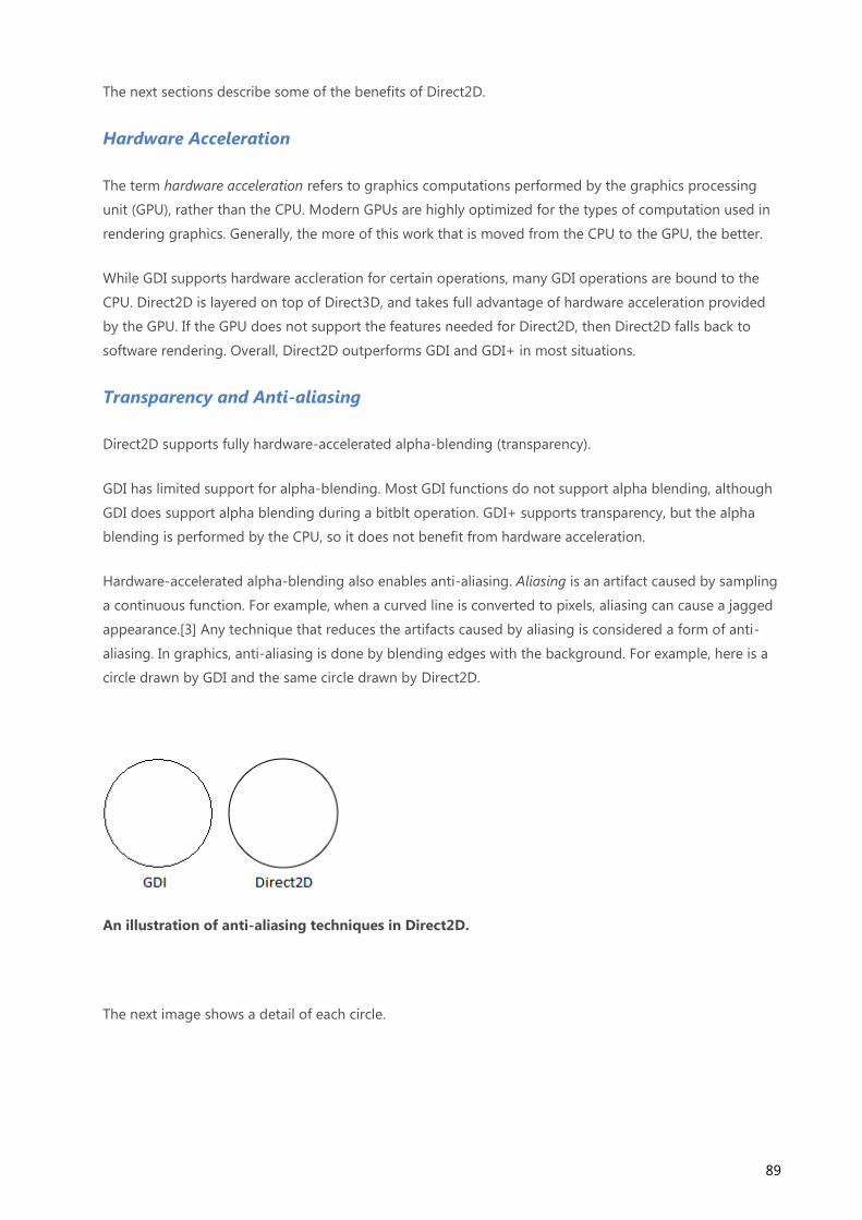
89
The next sections describe some of the benefits of Direct2D.
Hardware Acceleration
The term hardware acceleration refers to graphics computations performed by the graphics processing
unit (GPU), rather than the CPU. Modern GPUs are highly optimized for the types of computation used in
rendering graphics. Generally, the more of this work that is moved from the CPU to the GPU, the better.
While GDI supports hardware accleration for certain operations, many GDI operations are bound to the
CPU. Direct2D is layered on top of Direct3D, and takes full advantage of hardware acceleration provided
by the GPU. If the GPU does not support the features needed for Direct2D, then Direct2D falls back to
software rendering. Overall, Direct2D outperforms GDI and GDI+ in most situations.
Transparency and Anti-aliasing
Direct2D supports fully hardware-accelerated alpha-blending (transparency).
GDI has limited support for alpha-blending. Most GDI functions do not support alpha blending, although
GDI does support alpha blending during a bitblt operation. GDI+ supports transparency, but the alpha
blending is performed by the CPU, so it does not benefit from hardware acceleration.
Hardware-accelerated alpha-blending also enables anti-aliasing. Aliasing is an artifact caused by sampling
a continuous function. For example, when a curved line is converted to pixels, aliasing can cause a jagged
appearance.[3] Any technique that reduces the artifacts caused by aliasing is considered a form of anti-
aliasing. In graphics, anti-aliasing is done by blending edges with the background. For example, here is a
circle drawn by GDI and the same circle drawn by Direct2D.
An illustration of anti-aliasing techniques in Direct2D.
The next image shows a detail of each circle.

90
A detail of the previous image.
The circle drawn by GDI (left) consists of black pixels that approximate a curve. The circle drawn by
Direct2D (right) uses blending to create a smoother curve.
GDI does not support anti-aliasing when it draws geometry (lines and curves). GDI can draw anti-aliased
text using ClearType; but otherwise, GDI text is aliased as well. Aliasing is particularly noticeable for text,
because the jagged lines disrupt the font design, making the text less readable. Although GDI+ supports
anti-aliasing, it is applied by the CPU, so the performance is not as good as Direct2D.
Vector Graphics
Direct2D supports vector graphics. In vector graphics, mathematical formulas are used to represent lines
and curves. These formulas are not dependent on screen resolution, so they can be scaled to arbitrary
dimensions. Vector graphics are particularly useful when an image must be scaled to support different
monitor sizes or screen resolutions.

91
The Desktop Window Manager
Before Windows Vista, a Windows program would draw directly to the screen. In other words, the
program would write directly to the memory buffer shown by the video card. This approach can cause
visual artifacts if a window does not repaint itself correctly. For example, if the user drags one window
over another window, and the window underneath does not repaint itself quickly enough, the top-most
window can leave a trail:
A screenshot that shows repaint artifacts.
The trail is caused because both windows paint to the same area of memory. As the top-most window is
dragged, the window below it must be repainted. If the repainting is too slow, it causes the artifacts
shown in the previous image.
Windows Vista fundamentally changed how windows are drawn, by introducing the Desktop Window
Manager (DWM). When the DWM is enabled, a window no longer draws directly to the display buffer.
Instead, each window draws to an offscreen memory buffer, also called an offscreen surface. The DWM
then composites these surfaces to the screen.

92
A diagram that shows how the DWM composites the desktop.
The DWM provides several advantages over the old graphics architecture.
Fewer repaint messages. When a window is obstructed by another window, the obstructed
window does not need to repaint itself.
Reduced artifacts. Previously, dragging a window could create visual artifacts, as described.
Visual effects. Because the DWM is in charge of compositing the screen, it can render translucent
and blurred areas of the window.
Automatic scaling for high DPI. Although scaling is not the ideal way to handle high DPI, it is a
viable fallback for older applications that were not designed for high DPI settings. (We will return
to this topic later, in the section DPI and Device-Independent Pixels.)
Alternative views. The DWM can use the offscreen surfaces in various interesting ways. For
example, the DWM is the technology behind Windows Flip 3D, thumbnails, and animated
transitions.
Note, however, that the DWM is not guaranteed to be enabled. The graphics card might not support the
DWM system requirements, and users can disable the DWM through the System Properties control
panel. That means your program should not rely on the repainting behavior of the DWM. Test your
program with DWM disabled to make sure that it repaints correctly.

93
Retained Mode Versus Immediate Mode
Graphics APIs can be divided into retained-mode APIs and immediate-mode APIs. Direct2D is an
immediate-mode API. Windows Presentation Foundation (WPF) is an example of a retained-mode API.
A retained-mode API is declarative. The application constructs a scene from graphics primitives, such as
shapes and lines. The graphics library stores a model of the scene in memory. To draw a frame, the
graphics library transforms the scene into a set of drawing commands. Between frames, the graphics
library keeps the scene in memory. To change what is rendered, the application issues a command to
update the scene — for example, to add or remove a shape. The library is then responsible for redrawing
the scene.
A diagram that shows retained-mode graphics.
An immediate-mode API is procedural. Each time a new frame is drawn, the application directly issues the
drawing commands. The graphics library does not store a scene model between frames. Instead, the
application keeps track of the scene.
A diagram that shows immediate-mode graphics.

94
Retained-mode APIs can be simpler to use, because the API does more of the work for you, such as
initialization, state maintenance, and cleanup. On the other hand, they are often less flexible, because the
API imposes its own scene model. Also, a retained-mode API can have higher memory requirements,
because it needs to provide a general-purpose scene model. With an immediate-mode API, you can
implement targeted optimizations.
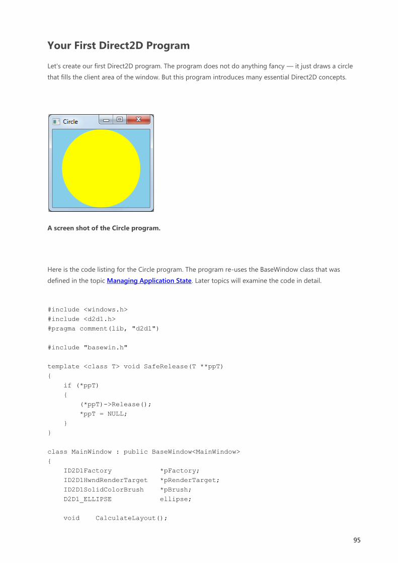
95
Your First Direct2D Program
Let's create our first Direct2D program. The program does not do anything fancy — it just draws a circle
that fills the client area of the window. But this program introduces many essential Direct2D concepts.
A screen shot of the Circle program.
Here is the code listing for the Circle program. The program re-uses the BaseWindow class that was
defined in the topic Managing Application State. Later topics will examine the code in detail.
#include <windows.h>
#include <d2d1.h>
#pragma comment(lib, "d2d1")
#include "basewin.h"
template <class T> void SafeRelease(T **ppT)
{
if (*ppT)
{
(*ppT)->Release();
*ppT = NULL;
}
}
class MainWindow : public BaseWindow<MainWindow>
{
ID2D1Factory *pFactory;
ID2D1HwndRenderTarget *pRenderTarget;
ID2D1SolidColorBrush *pBrush;
D2D1_ELLIPSE ellipse;
void CalculateLayout();

96
HRESULT CreateGraphicsResources();
void DiscardGraphicsResources();
void OnPaint();
void Resize();
public:
MainWindow() : pFactory(NULL), pRenderTarget(NULL), pBrush(NULL)
{
}
PCWSTR ClassName() const { return L"Circle Window Class"; }
LRESULT HandleMessage(UINT uMsg, WPARAM wParam, LPARAM lParam);
};
// Recalculate drawing layout when the size of the window changes.
void MainWindow::CalculateLayout()
{
if (pRenderTarget != NULL)
{
D2D1_SIZE_F size = pRenderTarget->GetSize();
const float x = size.width / 2;
const float y = size.height / 2;
const float radius = min(x, y);
ellipse = D2D1::Ellipse(D2D1::Point2F(x, y), radius, radius);
}
}
HRESULT MainWindow::CreateGraphicsResources()
{
HRESULT hr = S_OK;
if (pRenderTarget == NULL)
{
RECT rc;
GetClientRect(m_hwnd, &rc);
D2D1_SIZE_U size = D2D1::SizeU(rc.right, rc.bottom);
hr = pFactory->CreateHwndRenderTarget(
D2D1::RenderTargetProperties(),
D2D1::HwndRenderTargetProperties(m_hwnd, size),
&pRenderTarget);
if (SUCCEEDED(hr))
{
const D2D1_COLOR_F color = D2D1::ColorF(1.0f, 1.0f, 0);
hr = pRenderTarget->CreateSolidColorBrush(color, &pBrush);
if (SUCCEEDED(hr))
{

97
CalculateLayout();
}
}
}
return hr;
}
void MainWindow::DiscardGraphicsResources()
{
SafeRelease(&pRenderTarget);
SafeRelease(&pBrush);
}
void MainWindow::OnPaint()
{
HRESULT hr = CreateGraphicsResources();
if (SUCCEEDED(hr))
{
PAINTSTRUCT ps;
BeginPaint(m_hwnd, &ps);
pRenderTarget->BeginDraw();
pRenderTarget->Clear( D2D1::ColorF(D2D1::ColorF::SkyBlue) );
pRenderTarget->FillEllipse(ellipse, pBrush);
hr = pRenderTarget->EndDraw();
if (FAILED(hr) || hr == D2DERR_RECREATE_TARGET)
{
DiscardGraphicsResources();
}
EndPaint(m_hwnd, &ps);
}
}
void MainWindow::Resize()
{
if (pRenderTarget != NULL)
{
RECT rc;
GetClientRect(m_hwnd, &rc);
D2D1_SIZE_U size = D2D1::SizeU(rc.right, rc.bottom);
pRenderTarget->Resize(size);
CalculateLayout();
InvalidateRect(m_hwnd, NULL, FALSE);
}
}
int WINAPI wWinMain(HINSTANCE hInstance, HINSTANCE, PWSTR, int nCmdShow)

98
{
MainWindow win;
if (!win.Create(L"Circle", WS_OVERLAPPEDWINDOW))
{
return 0;
}
ShowWindow(win.Window(), nCmdShow);
// Run the message loop.
MSG msg = { };
while (GetMessage(&msg, NULL, 0, 0))
{
TranslateMessage(&msg);
DispatchMessage(&msg);
}
return 0;
}
LRESULT MainWindow::HandleMessage(UINT uMsg, WPARAM wParam, LPARAM lParam)
{
switch (uMsg)
{
case WM_CREATE:
if (FAILED(D2D1CreateFactory(
D2D1_FACTORY_TYPE_SINGLE_THREADED, &pFactory)))
{
return -1; // Fail CreateWindowEx.
}
return 0;
case WM_DESTROY:
DiscardGraphicsResources();
SafeRelease(&pFactory);
PostQuitMessage(0);
return 0;
case WM_PAINT:
OnPaint();
return 0;
case WM_SIZE:
Resize();
return 0;
}
return DefWindowProc(m_hwnd, uMsg, wParam, lParam);
}

99
You can download the complete Visual Studio project from Direct2D Circle Sample.
The D2D1 Namespace
The D2D1 namespace contains helper functions and classes. These are not strictly part of the Direct2D API
— you can program Direct2D without using them — but they help simplify your code. The D2D1
namespace contains:
A ColorF class for constructing color values.
A Matrix3x2F for constructing transformation matrices.
A set of functions to initialize Direct2D structures.
You will see examples of the D2D1 namespace throughout this module.

100
Render Targets, Devices, and Resources
A render target is simply the location where your program will draw. Typically, the render target is a
window (specifically, the client area of the window). It could also be a bitmap in memory that is not
displayed. A render target is represented by the ID2D1RenderTarget interface.
A device is an abstraction that represents whatever actually draws the pixels. A hardware device uses the
GPU for faster performance, whereas a software device uses the CPU. The application does not create the
device. Instead, the device is created implicitly when the application creates the render target. Each render
target is associated with a particular device, either hardware or software.
A diagram that shows the relation between a render target and a device.
A resource is an object that the program uses for drawing. Here are some examples of resources that are
defined in Direct2D:
Brush. Controls how lines and regions are painted. Brush types include solid-color brushes and
gradiant brushes.
Stroke style. Controls the appearance of a line—for example, dashed or solid.
Geometry. Represents a collection of lines and curves.
Mesh. A shape formed out of triangles. Mesh data can be consumed directly by the GPU, unlike
geometry data, which must be converted before rendering.
Render targets are also considered a type of resource.
Some resources benefit from hardware acceleration. A resource of this type is always associated with a
particular device, either hardware (GPU) or software (CPU). This type of resource is called device-
dependent. Brushes and meshes are examples of device-dependent resources. If the device becomes
unavailable, the resource must be re-created for a new device.

101
Other resources are kept in CPU memory, regardless of what device is used. These resources are device-
independent, because they are not associated with a particular device. It is not necessary to re-create
device-independent resources when the device changes. Stroke styles and geometries are device-
independent resources.
The MSDN documentation for each resource states whether the resource is device-dependent or device-
independent. Every resource type is represented by an interface that derives from ID2D1Resource. For
example, brushes are represented by the ID2D1Brush interface.
The Direct2D Factory Object
The first step when using Direct2D is to create an instance of the Direct2D factory object. In computer
programming, a factory is an object that creates other objects. The Direct2D factory creates the following
types of objects:
Render targets.
Device-independent resources, such as stroke styles and geometries.
Device-dependent resources, such as brushes and bitmaps, are created by the render target object.
A diagram that shows the Direct2D factory.
To create the Direct2D factory object, call the D2D1CreateFactory function.
ID2D1Factory *pFactory = NULL;
HRESULT hr = D2D1CreateFactory(D2D1_FACTORY_TYPE_SINGLE_THREADED, &pFactory);

102
The first parameter is a flag that specifies creation options. The D2D1_FACTORY_TYPE_SINGLE_THREADED
flag means that you will not call Direct2D from multiple threads. To support calls from multiple threads,
specify D2D1_FACTORY_TYPE_MULTI_THREADED. If your program uses a single thread to call into
Direct2D, the single-threaded option is more efficient.
The second parameter to the D2D1CreateFactory function receives a pointer to the ID2D1Factory
interface.
You should create the Direct2D factory object before the first WM_PAINT message. The WM_CREATE
message handler is a good place to create the factory:
case WM_CREATE:
if (FAILED(D2D1CreateFactory(
D2D1_FACTORY_TYPE_SINGLE_THREADED, &pFactory)))
{
return -1; // Fail CreateWindowEx.
}
return 0;
Creating Direct2D Resources
The Circle program uses the following device-dependent resources:
A render target that is associated with the application window.
A solid-color brush to paint the circle.
Each of these resources is represented by a COM interface:
The ID2D1HwndRenderTarget interface represents the render target.
The ID2D1SolidColorBrush interface represents the brush.
The Circle program stores pointers to these interfaces as member variables of the MainWindow class:
ID2D1HwndRenderTarget *pRenderTarget;
ID2D1SolidColorBrush *pBrush;
The following code creates these two resources.

103
HRESULT MainWindow::CreateGraphicsResources()
{
HRESULT hr = S_OK;
if (pRenderTarget == NULL)
{
RECT rc;
GetClientRect(m_hwnd, &rc);
D2D1_SIZE_U size = D2D1::SizeU(rc.right, rc.bottom);
hr = pFactory->CreateHwndRenderTarget(
D2D1::RenderTargetProperties(),
D2D1::HwndRenderTargetProperties(m_hwnd, size),
&pRenderTarget);
if (SUCCEEDED(hr))
{
const D2D1_COLOR_F color = D2D1::ColorF(1.0f, 1.0f, 0);
hr = pRenderTarget->CreateSolidColorBrush(color, &pBrush);
if (SUCCEEDED(hr))
{
CalculateLayout();
}
}
}
return hr;
}
To create a render target for a window, call the ID2D1Factory::CreateHwndRenderTarget method on
the Direct2D factory.
The first parameter specifies options that are common to any type of render target. Here, we pass
in default options by calling the helper function D2D1::RenderTargetProperties.
The second parameter specifies the handle to the window plus the size of the render target, in
pixels.
The third parameter receives an ID2D1HwndRenderTarget pointer.
To create the solid-color brush, call the ID2D1RenderTarget::CreateSolidColorBrush method on the
render target. The color is given as a D2D1_COLOR_F value. For more information about colors in
Direct2D, see Using Color in Direct2D.
Also, notice that if the render target already exists, the CreateGraphicsResources method returns S_OK
without doing anything. The reason for this design will become clear in the next topic.

104
Drawing with Direct2D
After you create your graphics resources, you are ready to draw.
Drawing an Ellipse
The Circle program performs very simple drawing logic:
1. Fill the background with a solid color.
2. Draw a filled circle.
A screen shot of the Circle program.
Because the render target is a window (as opposed to a bitmap or other offscreen surface), drawing is
done in response to WM_PAINT messages. The following code shows the window procedure for the
Circle program.
LRESULT MainWindow::HandleMessage(UINT uMsg, WPARAM wParam, LPARAM lParam)
{
switch (uMsg)
{
case WM_PAINT:
OnPaint();
return 0;
// Other messages not shown...
return DefWindowProc(m_hwnd, uMsg, wParam, lParam);
}

105
Here is the code that draws the circle.
void MainWindow::OnPaint()
{
HRESULT hr = CreateGraphicsResources();
if (SUCCEEDED(hr))
{
PAINTSTRUCT ps;
BeginPaint(m_hwnd, &ps);
pRenderTarget->BeginDraw();
pRenderTarget->Clear( D2D1::ColorF(D2D1::ColorF::SkyBlue) );
pRenderTarget->FillEllipse(ellipse, pBrush);
hr = pRenderTarget->EndDraw();
if (FAILED(hr) || hr == D2DERR_RECREATE_TARGET)
{
DiscardGraphicsResources();
}
EndPaint(m_hwnd, &ps);
}
}
The ID2D1RenderTarget interface is used for all drawing operations. The program's OnPaint method
does the following:
1. The ID2D1RenderTarget::BeginDraw method signals the start of drawing.
2. The ID2D1RenderTarget::Clear method fills the entire render target with a solid color. The color
is given as a D2D1_COLOR_F structure. You can use the D2D1::ColorF class to initialize the
structure. For more information, see Using Color in Direct2D.
3. The ID2D1RenderTarget::FillEllipse method draws a filled ellipse, using the specified brush for
the fill. An ellipse is specified by a center point and the x- and y-radii. If the x- and y-radii are the
same, the result is a circle.
4. The ID2D1RenderTarget::EndDraw method signals the completion of drawing for this frame. All
drawing operations must be placed between calls to BeginDraw and EndDraw.
The BeginDraw, Clear, and FillEllipse methods all have a void return type. If an error occurs during the
execution of any of these methods, the error is signaled through the return value of the EndDraw
method. The CreateGraphicsResources method is shown in the topic Creating Direct2D Resources. This
method creates the render target and the solid-color brush.

106
The device might buffer the drawing commands and defer executing them until EndDraw is called. You
can force the device to execute any pending drawing commands by calling ID2D1RenderTarget::Flush.
Flushing can reduce performance, however.
Handling Device Loss
While your program is running, the graphics device that you are using might become unavailable. For
example, the device can be lost if the display resolution changes, or if the user removes the display
adapter. If the device is lost, the render target also becomes invalid, along with any device-dependent
resources that were associated with the device. Direct2D signals a lost device by returning the error code
D2DERR_RECREATE_TARGET from the EndDraw method. If you receive this error code, you must re-create
the render target and all device-dependent resources.
To discard a resource, simply release the interface for that resource.
void MainWindow::DiscardGraphicsResources()
{
SafeRelease(&pRenderTarget);
SafeRelease(&pBrush);
}
Creating a resource can be an expensive operation, so do not recreate your resources for every
WM_PAINT message. Create a resource once, and cache the resource pointer until the resource becomes
invalid due to device loss, or until you no longer need that resource.
The Direct2D Render Loop
Regardless of what you draw, your program should perform a loop similar to following.
1. Create device-independent resources.
2. Render the scene.
Check if a valid render target exists. If not, create the render target and the device-
dependent resources.
Call ID2D1RenderTarget::BeginDraw.
Issue drawing commands.
Call ID2D1RenderTarget::EndDraw.
If EndDraw returns D2DERR_RECREATE_TARGET, discard the render target and device-
dependent resources.
3. Repeat step 2 whenever you need to update or redraw the scene.
If the render target is a window, step 2 occurs whenever the window receives a WM_PAINT message.

107
The loop shown here handles device loss by discarding the device-dependent resources and re-creating
them at the start of the next loop (step 2a).

108
DPI and Device-Independent Pixels
To program effectively with Windows graphics, you must understand two related concepts:
Dots per inch (DPI)
Device-independent pixel (DIPs).
Let's start with DPI. This will require a short detour into typography. In typography, the size of type is
measured in units called points. One point equals 1/72 of an inch.
1 pt = 1/72 inch
Note This is the desktop publishing definition of point. Historically, the exact measure of a point has
varied.
For example, a 12-point font is designed to fit within a 1/6" (12/72) line of text. Obviously, this does not
mean that every character in the font is exactly 1/6" tall. In fact, some characters might be taller than 1/6".
For example, in many fonts the character Å is taller than the nominal height of the font. To display
correctly, the font needs some additional space between the text. This space is called the leading.
The following illustration shows a 72-point font. The solid lines show a 1" tall bounding box around the
text. The dashed line is called the baseline. Most of the characters in a font rest on the baseline. The
height of the font includes the portion above the baseline (the ascent) and the portion below the baseline
(the descent). In the font shown here, the ascent is 56 points and the descent is 16 points.
An illustration that shows a 72-point font.
When it comes to a computer display, however, measuring text size is problematic, because pixels are not
all the same size. The size of a pixel depends on two factors: the display resolution, and the physical size
of the monitor. Therefore, physical inches are not a useful measure, because there is no fixed relation
between physical inches and pixels. Instead, fonts are measured in logical units. A 72-point font is defined
to be one logical inch tall. Logical inches are then converted to pixels. For many years, Windows used the
following conversion: One logical inch equals 96 pixels. Using this scaling factor, a 72-point font is
rendered as 96 pixels tall. A 12-point font is 16 pixels tall.

109
12 points = 12/72 logical inch = 1/6 logical inch = 96/6 pixels = 16 pixels
This scaling factor is described as 96 dots per inch (DPI). The term dots derives from printing, where
physical dots of ink are put onto paper. For computer displays, it would be more accurate to say 96 pixels
per logical inch, but the term DPI has stuck.
Because actual pixel sizes vary, text that is readable on one monitor might be too small on another
monitor. Also, people have different preferences—some people prefer larger text. For this reason,
Windows enables the user to change the DPI setting. For example, if the user sets the display to 144 DPI, a
72-point font is 144 pixels tall. The standard DPI settings are 100% (96 DPI), 125% (120 DPI), and 150%
(144 DPI). The user can also apply a custom setting. Starting in Windows 7, DPI is a per-user setting.
DWM Scaling
If a program does not account for DPI, the following defects might be apparent at high-DPI settings:
Clipped UI elements.
Incorrect layout.
Pixilated bitmaps and icons.
Incorrect mouse coordinates, which can affect hit testing, drag and drop, and so forth.
To ensure that older programs work at high-DPI settings, the DWM implements a useful fallback. If a
program is not marked as being DPI aware, the DWM will scale the entire UI to match the DPI setting. For
example, at 144 DPI, the UI is scaled by 150%, including text, graphics, controls, and window sizes. If the
program creates a 500 × 500 window, the window actually appears as 750 × 750 pixels, and the contents
of the window are scaled accordingly.
This behavior means that older programs "just work" at high-DPI settings. However, scaling also results in
a somewhat blurry appearance, because the scaling is applied after the window is drawn.
DPI-Aware Applications
To avoid DWM scaling, a program can mark itself as DPI-aware. This tells the DWM not to perform any
automatic DPI scaling. All new applications should be designed to be DPI-aware, because DPI awareness
improves the appearance of the UI at higher DPI settings.
A program declares itself DPI-aware through its application manifest. A manifest is a simply an XML file
that describes a DLL or application. The manifest is typically embedded in the executable file, although it
can be provided as a separate file. A manifest contains information such as DLL dependencies, the
requested privilege level, and what version of Windows the program was designed for.
To declare that your program is DPI-aware, include the following information in the manifest.

110
<assembly xmlns="urn:schemas-microsoft-com:asm.v1" manifestVersion="1.0"
xmlns:asmv3="urn:schemas-microsoft-com:asm.v3" >
<asmv3:application>
<asmv3:windowsSettings
xmlns="http://schemas.microsoft.com/SMI/2005/WindowsSettings">
<dpiAware>true</dpiAware>
</asmv3:windowsSettings>
</asmv3:application>
</assembly>
The listing shown here is only a partial manifest, but the Visual Studio linker generates the rest of the
manifest for you automatically. To include a partial manifest in your project, perform the following steps
in Visual Studio.
1. On the Project menu, click Property.
2. In the left pane, expand Configuration Properties, expand Manifest Tool, and then click Input
and Output.
3. In the Additional Manifest Files text box, type the name of the manifest file, and then click OK.
By marking your program as DPI-aware, you are telling the DWM not to scale your application window.
Now if you create a 500 × 500 window, the window will occupy 500 × 500 pixels, regardless of the user's
DPI setting.
GDI and DPI
GDI drawing is measured in pixels. That means if your program is marked as DPI-aware, and you ask GDI
to draw a 200 × 100 rectangle, the resulting rectangle will be 200 pixels wide and 100 pixels tall on the
screen. However, GDI font sizes are scaled to the current DPI setting. In other words, if you create a 72-
point font, the size of the font will be 96 pixels at 96 DPI, but 144 pixels at 144 DPI. Here is a 72 point font
rendered at 144 DPI using GDI.
A diagram that shows DPI font scaling in GDI.

111
If your application is DPI-aware and you use GDI for drawing, scale all of your drawing coordinates to
match the DPI.
Direct2D and DPI
Direct2D automatically performs scaling to match the DPI setting. In Direct2D, coordinates are measured
in units called device-independent pixels (DIPs). A DIP is defined as 1/96th of a logical inch. In Direct2D, all
drawing operations are specified in DIPs and then scaled to the current DPI setting.
DPI setting DIP size
96 1 pixel
120 1.25 pixels
144 1.5 pixels
For example, if the user's DPI setting is 144 DPI, and you ask Direct2D to draw a 200 × 100 rectangle, the
rectangle will be 300 × 150 physical pixels. In addition, DirectWrite measures font sizes in DIPs, rather
than points. To create a 12-point font, specify 16 DIPs (12 points = 1/6 logical inch = 96/6 DIPs). When
the text is drawn on the screen, Direct2D converts the DIPs to physical pixels. The benefit of this system is
that the units of measurement are consistent for both text and drawing, regardless of the current DPI
setting.
A word of caution: Mouse and window coordinates are still given in physical pixels, not DIPs. For example,
if you process the WM_LBUTTONDOWN message, the mouse-down position is given in physical pixels.
To draw a point at that position, you must convert the pixel coordinates to DIPs.
Converting Physical Pixels to DIPs
The conversion from physical pixels to DIPs uses the following formula.
DIPs = pixels / (DPI/96.0)
To get the DPI setting, call the ID2D1Factory::GetDesktopDpi method. The DPI is returned as two
floating-point values, one for the x-axis and one for the y-axis. In theory, these values can differ. Calculate
a separate scaling factor for each axis.
float g_DPIScaleX = 1.0f;
float g_DPIScaleY = 1.0f;
void InitializeDPIScale(ID2D1Factory *pFactory)
{

112
FLOAT dpiX, dpiY;
pFactory->GetDesktopDpi(&dpiX, &dpiY);
g_DPIScaleX = dpiX/96.0f;
g_DPIScaleY = dpiY/96.0f;
}
template <typename T>
float PixelsToDipsX(T x)
{
return static_cast<float>(x) / g_DPIScaleX;
}
template <typename T>
float PixelsToDipsY(T y)
{
return static_cast<float>(y) / g_DPIScaleY;
}
Here is an alternate way to get the DPI setting if you are not using Direct2D:
void InitializeDPIScale(HWND hwnd)
{
HDC hdc = GetDC(hwnd);
g_DPIScaleX = GetDeviceCaps(hdc, LOGPIXELSX) / 96.0f;
g_DPIScaleY = GetDeviceCaps(hdc, LOGPIXELSY) / 96.0f;
ReleaseDC(hwnd, hdc);
}
Resizing the Render Target
If the size of the window changes, you must resize the render target to match. In most cases, you will also
need to update the layout and repaint the window. The following code shows these steps.
void MainWindow::Resize()
{
if (pRenderTarget != NULL)
{
RECT rc;
GetClientRect(m_hwnd, &rc);
D2D1_SIZE_U size = D2D1::SizeU(rc.right, rc.bottom);

113
pRenderTarget->Resize(size);
CalculateLayout();
InvalidateRect(m_hwnd, NULL, FALSE);
}
}
The GetClientRect function gets the new size of the client area, in physical pixels (not DIPs). The
ID2D1HwndRenderTarget::Resize method updates the size of the render target, also specified in pixels.
The InvalidateRect function forces a repaint by adding the entire client area to the window's update
region. (See Painting the Window, in Module 1.)
As the window grows or shrinks, you will typically need to recalculate the position of the objects that you
draw. For example, in the circle program, the radius and center point must be updated:
void MainWindow::CalculateLayout()
{
if (pRenderTarget != NULL)
{
D2D1_SIZE_F size = pRenderTarget->GetSize();
const float x = size.width / 2;
const float y = size.height / 2;
const float radius = min(x, y);
ellipse = D2D1::Ellipse(D2D1::Point2F(x, y), radius, radius);
}
}
The ID2D1RenderTarget::GetSize method returns the size of the render target in DIPs (not pixels), which
is the appropriate unit for calculating layout. There is a closely related method,
ID2D1RenderTarget::GetPixelSize, that returns the size in physical pixels. For an HWND render target,
this value matches the size returned by GetClientRect. But remember that drawing is performed in DIPs,
not pixels.

114
Using Color in Direct2D
Direct2D uses the RGB color model, in which colors are formed by combining different values of red,
green, and blue. A fourth component, alpha, measures the transparency of a pixel. In Direct2D, each of
these components is a floating-point value with a range of [0.0–1.0]. For the three color components, the
value measures the intensity of the color. For the alpha component, 0.0 means completely transparent,
and 1.0 means completely opaque. The following table shows the colors that result from various
combinations of 100% intensity.
Red Green Blue Color
0 0 0 Black
1 0 0 Red
0 1 0 Green
0 0 1 Blue
0 1 1 Cyan
1 0 1 Magenta
1 1 0 Yellow
1 1 1 White
An image that shows RGB colors.
Color values between 0 and 1 result in different shades of these pure colors. Direct2D uses the
D2D1_COLOR_F structure to represent colors. For example, the following code specifies magenta.

115
// Initialize a magenta color.
D2D1_COLOR_F clr;
clr.r = 1;
clr.g = 0;
clr.b = 1;
clr.a = 1; // Opaque.
You can also specify a color using the D2D1::ColorF class, which derives from the D2D1_COLOR_F
structure.
// Equivalent to the previous example.
D2D1::ColorF clr(1, 0, 1, 1);
Alpha Blending
Alpha blending creates translucent areas by blending the foreground color with the background color,
using the following formula.
color = αf Cf + (1–αf) Cb
where Cb is the background color, Cf is the foreground color, and αf is the alpha value of the foreground
color. This formula is applied pairwise to each color component. For example, suppose the foreground
color is (R = 1.0, G= 0.4, B = 0.0), with alpha = 0.6, and the background color is (R = 0.0, G = 0.5, B = 1.0).
The resulting alpha-blended color is:
R = (1.0 × 0.6 + 0 × 0.4) = .6
G = (0.4 × 0.6 + 0.5 × 0.4) = .44
B = (0 × 0.6 + 1.0 × 0.4) = .40
The following image shows the result of this blending operation.

116
An image that shows alpha blending.
Pixel Formats
The D2D1_COLOR_F structure does not describe how a pixel is represented in memory. In most cases,
that doesn't matter. Direct2D handles all of the internal details of translating color information into pixels.
But you might need to know the pixel format if you are working directly with a bitmap in memory, or if
you combine Direct2D with Direct3D or GDI.
The DXGI_FORMAT enumeration defines a list of pixel formats. The list is fairly long, but only a few of
them are relevant to Direct2D. (The others are used by Direct3D).
Pixel format Description
DXGI_FORMAT_B8G8R8A8_UNORM
This is the most common pixel format. All pixel components (red,
green, blue, and alpha) are 8-bit unsigned integers. The components
are arranged in BGRA order in memory. (See illustration that follows.)
DXGI_FORMAT_R8G8B8A8_UNORM
Pixel components are 8-bit unsigned integers, in RGBA order. In
other words, the red and blue components are swapped, relative to
DXGI_FORMAT_B8G8R8A8_UNORM. This format is supported only
for hardware devices.
DXGI_FORMAT_A8_UNORM
This format contains an 8-bit alpha component, with no RGB
components. It is useful for creating opacity masks. To read more
about using opacity masks in Direct2D, see Compatible A8 Render
Targets Overview.
The following illustration shows BGRA pixel layout.

117
A diagram that shows BGRA pixel layout.
To get the pixel format of a render target, call ID2D1RenderTarget::GetPixelFormat. The pixel format
might not match the display resolution. For example, the display might be set to 16-bit color, even
though the render target uses 32-bit color.
Alpha Mode
A render target also has an alpha mode, which defines how the alpha values are treated.
Alpha mode Desciption
D2D1_ALPHA_MODE_IGNORE No alpha blending is performed. Alpha values are ignored.
D2D1_ALPHA_MODE_STRAIGHT Straight alpha. The color components of the pixel represent the
color intensity prior to alpha blending.
D2D1_ALPHA_MODE_PREMULTIPLIED
Premultiplied alpha. The color components of the pixel represent
the color intensity multiplied by the alpha value. This format is
more efficient to render than straight alpha, because the term (αf
× Cf) from the alpha-blending formula is pre-computed. However,
this format is not appropriate for storing in an image file.
Here is an example of the difference between straight alpha and premultiplied alpha. Suppose the desired
color is pure red (100% intensity) with 50% alpha. As a Direct2D type, this color would be represented as
(1, 0, 0, 0.5). Using straight alpha, and assuming 8-bit color components, the red component of the pixel is
0xFF. Using premultiplied alpha, the red component is scaled by 50% to equal 0x80.
The D2D1_COLOR_F data type always represents colors using straight alpha. Direct2D converts pixels to
premultiplied alpha format if needed.
If you know that your program will not perform any alpha blending, create the render target with the
D2D1_ALPHA_MODE_IGNORE alpha mode. This mode can improve performance, because Direct2D can

118
skip the alpha calculations. For more information, see Improving the Performance of Direct2D
Applications.

119
Applying Transforms in Direct2D
In Drawing with Direct2D, we saw that the ID2D1RenderTarget::FillEllipse method draws an ellipse that
is aligned to the x- and y-axes. But suppose you want to draw an ellipse tilted at an angle?
An image that shows a tilted ellipse.
By using transforms, you can alter a shape in the following ways.
Rotation around a point.
Scaling.
Translation (displacement in the X or Y direction).
Skew (also called shear).
A transform is a mathematical operation that maps a set of points to a new set of points. For example, the
following diagram shows a triangle rotated around the point P3. After the rotation is applied, the point P1
is mapped to P1', the point P2 is mapped to P2', and the point P3 maps to itself.
A diagram that shows rotation around a point.

120
Transforms are implemented using matrices. However, you don't need to understand the mathematics of
matrices in order to use them. If you want to learn more about the math, see Appendix: Matrix
Transforms.
To apply a transform in Direct2D, call the ID2D1RenderTarget::SetTransform method. This method
takes a D2D1_MATRIX_3X2_F structure that defines the transformation. You can initialize this structure
by calling methods on the D2D1::Matrix3x2F class. This class contains static methods that return a matrix
for each type of transform:
Matrix3x2F::Rotation
Matrix3x2F::Scale
Matrix3x2F::Translation
Matrix3x2F::Skew
For example, the following code applies a 20-degree rotation around the point (100, 100).
pRenderTarget->SetTransform(
D2D1::Matrix3x2F::Rotation(20, D2D1::Point2F(100,100)));
The transform is applied to all subsequent drawing operations until you call SetTransform again. To
remove the current transform, call SetTransform with the identity matrix, which is returned by the
Matrix3x2F::Identity function.
pRenderTarget->SetTransform(D2D1::Matrix3x2F::Identity());
Drawing Clock Hands
Let's put transforms to use by converting our Circle program into an analog clock. We can do this by
adding lines for the hands.
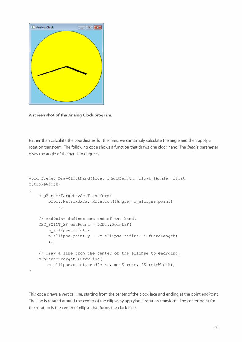
121
A screen shot of the Analog Clock program.
Rather than calculate the coordinates for the lines, we can simply calculate the angle and then apply a
rotation transform. The following code shows a function that draws one clock hand. The fAngle parameter
gives the angle of the hand, in degrees.
void Scene::DrawClockHand(float fHandLength, float fAngle, float
fStrokeWidth)
{
m_pRenderTarget->SetTransform(
D2D1::Matrix3x2F::Rotation(fAngle, m_ellipse.point)
);
// endPoint defines one end of the hand.
D2D_POINT_2F endPoint = D2D1::Point2F(
m_ellipse.point.x,
m_ellipse.point.y - (m_ellipse.radiusY * fHandLength)
);
// Draw a line from the center of the ellipse to endPoint.
m_pRenderTarget->DrawLine(
m_ellipse.point, endPoint, m_pStroke, fStrokeWidth);
}
This code draws a vertical line, starting from the center of the clock face and ending at the point endPoint.
The line is rotated around the center of the ellipse by applying a rotation transform. The center point for
the rotation is the center of ellipse that forms the clock face.

122
A diagram that shows the rotation of the clock hand.
The following code shows how then entire clock face is drawn.
void Scene::RenderScene()
{
m_pRenderTarget->Clear(D2D1::ColorF(D2D1::ColorF::SkyBlue));
m_pRenderTarget->FillEllipse(m_ellipse, m_pFill);
m_pRenderTarget->DrawEllipse(m_ellipse, m_pStroke);
// Draw hands
SYSTEMTIME time;
GetLocalTime(&time);
// 60 minutes = 30 degrees, 1 minute = 0.5 degree
const float fHourAngle = (360.0f / 12) * (time.wHour) + (time.wMinute *
0.5f);
const float fMinuteAngle =(360.0f / 60) * (time.wMinute);
DrawClockHand(0.6f, fHourAngle, 6);
DrawClockHand(0.85f, fMinuteAngle, 4);
// Restore the identity transformation.
m_pRenderTarget->SetTransform( D2D1::Matrix3x2F::Identity() );
}
You can download the complete Visual Studio project from Direct2D Clock Sample. (Just for fun, the
download version adds a radial gradiant to the clock face.)

123
Combining Transforms
The four basic transforms can be combined by multiplying two or more matrices. For example, the
following code combines a rotation with a translation.
const D2D1::Matrix3x2F rot = D2D1::Matrix3x2F::Rotation(20);
const D2D1::Matrix3x2F trans = D2D1::Matrix3x2F::Translation(40, 10);
pRenderTarget->SetTransform(rot * trans);
The Matrix3x2F class provides operator*() for matrix multiplication. The order in which you multiply the
matrices is important. Setting a transform (M × N) means "Apply M first, followed by N." For example,
here is rotation followed by translation:
A diagram that shows rotation followed by translation.
Here is the code for this transform:
const D2D1::Matrix3x2F rot = D2D1::Matrix3x2F::Rotation(45, center);
const D2D1::Matrix3x2F trans = D2D1::Matrix3x2F::Translation(x, 0);
pRenderTarget->SetTransform(rot * trans);
Now compare that transform with a transform in the reverse order, translation followed by rotation.

124
A diagram that shows translation followed by rotation.
The rotation is performed around the center of the original rectangle. Here is the code for this transform.
D2D1::Matrix3x2F rot = D2D1::Matrix3x2F::Rotation(45, center);
D2D1::Matrix3x2F trans = D2D1::Matrix3x2F::Translation(x, 0);
pRenderTarget->SetTransform(trans * rot);
As you can see, the matrices are the same, but the order of operations has changed. This happens
because matrix multiplication is not commutative: M × N ≠ N × M.

125
Appendix: Matrix Transforms
This topic provides a mathematical overview of matrix transforms for 2-D graphics. However, you don't
need to know matrix math in order to use transforms in Direct2D. Read this topic if you are interested in
the math; otherwise, feel free to skip this topic.
1. Introduction to Matrices
Matrix Operations
2. Affine Transforms
Translation Transform
Scaling Transform
Rotation Around the Origin
Rotation Around an Arbitrary Point
Skew Transform
3. Representing Transforms in Direct2D
4. Next
Introduction to Matrices
A matrix is a rectangular array of real numbers. The order of the matrix is the number of rows and
columns. For example, if the matrix has 3 rows and 2 columns, the order is 3 × 2. Matrices are usually
shown with the matrix elements enclosed in square brackets:
3 x 2 matrix.
Notation: A matrix is designated by a capital letter. Elements are designated by lowercase letters.
Subscripts indicate the row and column number of an element. For example, aij is the element at the i'th
row and j'th column of the matrix A.
The following diagram shows an i × j matrix, with the individual elements in each cell of the matrix.

126
A matrix with i rows and j columns.
Matrix Operations
This section describes the basic operations defined on matrices.
Addition. The sum A + B of two matrices is obtained by adding the corresponding elements of A and B:
A + B = [ aij ] + [ bij ] = [ aij + bij ]
Scalar multiplication, This operation multiplies a matrix by a real number. Given a real number k, the scalar
product kA is obtained by multiplying every element of A by k.
kA = k[ aij ] = [ k × aij ]
Matrix multiplication. Given two matrices A and B with order (m × n) and (n × p), the product C = A × B is
a matrix with order (m × p), defined as follows:
Matrix multiplication.
or, equivalently:
cij = ai1 x b1j + ai2 x b2j + ... + ain + bnj
That is, to compute each element cij, do the following:

127
1. Take the i'th row of A and the j'th column of B.
2. Multiply each pair of elements in the row and column: the first row entry by the first column entry,
the second row entry by the second column entry, and so forth.
3. Sum the result.
Here is an example of multiplying a (2 × 2) matrix by a (2 × 3) matrix.
Matrix multiplication.
Matrix multiplication is not commutative. That is, A × B ≠ B × A. Also, from the definition it follows that
not every pair of matrices can be multiplied. The number of columns in the left-hand matrix must equal
the number of rows in the right-hand matrix. Otherwise, the × operator is not defined.
Identify matrix. An identity matrix, designated I, is a square matrix defined as follows:
Iij = 1 if i = j, or 0 otherwise.
In other words, an identity matrix contains 1 for each element where the row number equals the column
number, and zero for all other elements. For example, here is the 3 × 3 identity matrix.
Identity matrix.
The following equalities hold for any matrix M.
M x I = M
I x M = M
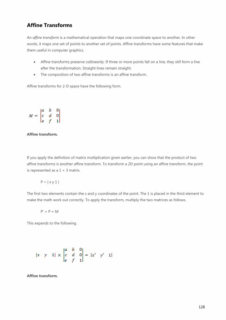
128
Affine Transforms
An affine transform is a mathematical operation that maps one coordinate space to another. In other
words, it maps one set of points to another set of points. Affine transforms have some features that make
them useful in computer graphics.
Affine transforms preserve collinearity. If three or more points fall on a line, they still form a line
after the transformation. Straight lines remain straight.
The composition of two affine transforms is an affine transform.
Affine transforms for 2-D space have the following form.
Affine transform.
If you apply the definition of matrix multiplication given earlier, you can show that the product of two
affine transforms is another affine transform. To transform a 2D point using an affine transform, the point
is represented as a 1 × 3 matrix.
P = | x y 1 |
The first two elements contain the x and y coordinates of the point. The 1 is placed in the third element to
make the math work out correctly. To apply the transform, multiply the two matrices as follows.
P' = P × M
This expands to the following.
Affine transform.

129
where
x' = ax + cy + e
y' = bx + dy + f
To get the transformed point, take the first two elements of matrix P'.
p = (x', y') = (ax + cy + e, bx + dy + f)
Note A 1 × n matrix is called a row vector. Direct2D and Direct3D both use row vectors to represent
points in 2D or 3D space. You can get an equivalent result by using a column vector (n × 1) and
transposing the transform matrix. Most graphics texts use the column vector form. This topic presents the
row vector form for consistency with Direct2D and Direct3D.
The next several sections derive the basic transforms.
Translation Transform
The translation transform matrix has the following form.
Translation transform.
Plugging a point P into this equation yields:
P' = (x + dx, y + dy)
which corresponds to the point (x, y) translated by dx in the X-axis and dy in the Y-axis.
A diagram that shows translation of two points.

130
Scaling Transform
The scaling transform matrix has the following form.
Scaling transform.
Plugging a point P into this equation yields:
P' = (x ∙ dx, y ∙ dy)
which corresponds to the point (x,y) scaled by dx and dy.
A diagram that shows scaling of two points.
Rotation Around the Origin
The matrix to rotate a point around the origin has the following form.
Rotation transform.

131
The transformed point is:
P' = (xcosΘ – ysinΘ, xsinΘ + ycosΘ)
Proof. To show that P' represents a rotation, consider the following diagram.
A diagram that shows rotation around the origin.
Given:
P = (x,y)
The original point to transform.
Φ
The angle formed by the line (0,0) to P.
Θ
The angle by which to rotate (x,y) about the origin.
P' = (x',y')
The transformed point.
R

132
The length of the line (0,0) to P. Also the radius of the circle of rotation.
Note This diagram uses the standard coordinate system used in geometry, where the positive y-axis
points up. Direct2D uses the Windows coordinate system, where the positive y-axis points down.
The angle between the x-axis and the line (0,0) to P' is Φ + Θ. The following identities hold:
x = R cosΦ
y = R sinΦ
x' = R cos(Φ + Θ)
y' = R sin(Φ+ Θ)
Now solve for x' and y' in terms of Θ. By the trigonometric addition formulas:
x' = R(cosΦcosΘ – sinΦsinΘ) = RcosΦcosΘ – RsinΦsinΘ
y' = R(sinΦcosΘ + cosΦsinΘ) = RsinΦcosΘ + RcosΦsinΘ
Substituting, we get:
x' = xcosΘ – ysinΘ
y' = xsinΘ + ycosΘ
which corresponds to the transformed point P' shown earlier.
Rotation Around an Arbitrary Point
To rotate around a point (x,y) other than the origin, the following matrix is used.
Rotation transform.
You can derive this matrix by taking the point (x,y) to be the origin.
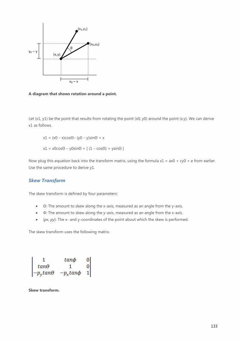
133
A diagram that shows rotation around a point.
Let (x1, y1) be the point that results from rotating the point (x0, y0) around the point (x,y). We can derive
x1 as follows.
x1 = (x0 – x)cosΘ– (y0 – y)sinΘ + x
x1 = x0cosΘ – y0sinΘ + [ (1 – cosΘ) + ysinΘ ]
Now plug this equation back into the transform matrix, using the formula x1 = ax0 + cy0 + e from earlier.
Use the same procedure to derive y1.
Skew Transform
The skew transform is defined by four parameters:
Θ: The amount to skew along the x-axis, measured as an angle from the y-axis.
Φ: The amount to skew along the y-axis, measured as an angle from the x-axis.
(px, py): The x- and y-coordinates of the point about which the skew is performed.
The skew transform uses the following matrix.
Skew transform.

134
The transformed point is:
P' = (x + ytanΘ – pytanΘ, y + xtanΦ) – pytanΦ
or equivalently:
P' = (x + (y – py)tanΘ, y + (x – px)tanΦ)
To see how this transform works, consider each component individually. The Θ parameter moves every
point in the x direction by an amount equal to tanΘ. The following diagram shows the relation between Θ
and the x-axis skew.
A diagram that shows skew along the x-axis.
Here is the same skew applied to a rectangle:
A diagram that shows skew along the x-axis.
The Φ parameter has the same effect, but along the y-axis:

135
A diagram that shows skew along the y-axis.
The next diagram shows y-axis skew applied to a rectangle.
A diagram that shows skew along the y-axis.
Finally, the parameters px and py shift the center point for the skew along the x- and y-axes.
Representing Transforms in Direct2D
All Direct2D transforms are affine transforms. Direct2D does not support non-affine transforms.
Transforms are represented by the D2D1_MATRIX_3X2_F structure. This structure defines a 3 × 2 matrix.
Because the third column of an affine transform is always the same ([0, 0, 1]), and because Direct2D does
not support non-affine transforms, there is no need to specify the entire 3 × 3 matrix. Internally, Direct2D
uses 3 × 3 matrices to compute the transforms.
The members of the D2D1_MATRIX_3X2_F are named according to their index position: the _11 member
is element (1,1), the _12 member is element (1,2), and so forth. Although you can initialize the structure
members directly, it is recommended to use the D2D1::Matrix3x2F class. This class inherits
D2D1_MATRIX_3X2_F and provides helper methods for creating any of the basic affine transforms. The
class also defines operator*() for composing two or more transforms, as described in Applying
Transforms in Direct2D.

136

137
Module 4. User Input
Previous modules have explored creating a window, handling window messages, and basic drawing with
2D graphics. In this module, we look at mouse and keyboard input. By the end of this module, you will be
able to write a simple drawing program that uses the mouse and keyboard.
In This Section
Mouse Input
Responding to Mouse Clicks
Mouse Movement
Miscellaneous Mouse Operations
Keyboard Input
Accelerator Tables
Setting the Cursor Image
User Input: Extended Example

138
Mouse Input
Windows supports mice with up to five buttons: left, middle, and right, plus two additional buttons called
XBUTTON1 and XBUTTON2.
An illustration that shows the left (1), right (2), middle (3), and XBUTTON1 (4) buttons.
Most mice for Windows have at least the left and right buttons. The left mouse button is used for
pointing, selecting, dragging, and so forth. The right mouse button typically displays a context menu.
Some mice have a scroll wheel located between the left and right buttons. Depending on the mouse, the
scroll wheel might also be clickable, making it the middle button.
The XBUTTON1 and XBUTTON2 buttons are often located on the sides of the mouse, near the base. These
extra buttons are not present on all mice. If present, the XBUTTON1 and XBUTTON2 buttons are often
mapped to an application function, such as forward and backward navigation in a Web browser.
Left-handed users often find it more comfortable to swap the functions of the left and right buttons—
using the right button as the pointer, and the left button to show the context menu. For this reason, the
Windows help documentation uses the terms primary button and secondary button, which refer to logical
function rather than physical placement. In the default (right-handed) setting, the left button is the
primary button and the right is the secondary button. However, the terms right click and left click refer to
logical actions. Right clicking means clicking the primary button, whether that button is physically on the
right or left side of the mouse.
Regardless of how the user configures the mouse, Windows automatically translates mouse messages so
they are consistent. The user can swap the primary and secondary buttons in the middle of using your
program, and it will not affect how your program behaves.
MSDN documentation uses the terms right button and left button to mean primary and secondary button.
This terminology is consistent with the names of the window messages for mouse input. Just remember
that the physical left and right buttons might be swapped.

139
Responding to Mouse Clicks
If the user clicks a mouse button while the cursor is over the client area of a window, the window receives
one of the following messages.
Message Meaning
WM_LBUTTONDOWN Left button down
WM_LBUTTONUP Left button up
WM_MBUTTONDOWN Middle button down
WM_MBUTTONUP Middle button up
WM_RBUTTONDOWN Right button down
WM_RBUTTONUP Right button up
WM_XBUTTONDOWN XBUTTON1 or XBUTTON2 down
WM_XBUTTONUP XBUTTON1 or XBUTTON2 up
Recall that the client area is the portion of the window that excludes the frame. For more information
about client areas, see What Is a Window?
Mouse Coordinates
In all of these messages, the lParam parameter contains the x- and y-coordinates of the mouse pointer.
The lowest 16 bits of lParam contain the x-coordinate, and the next 16 bits contain the y-coordinate. Use
the GET_X_LPARAM and GET_Y_LPARAM macros to unpack the coordinates from lParam.
int xPos = GET_X_LPARAM(lParam);
int yPos = GET_Y_LPARAM(lParam);
These macros are defined in the header file WindowsX.h.

140
On 64-bit Windows, lParam is 64-bit value. The upper 32 bits of lParam are not used. The MSDN
documentation mentions the "low-order word" and "high-order word" of lParam. In the 64-bit case, this
means the low- and high-order words of the lower 32 bits. The macros extract the right values, so if you
use them, you will be safe.
Mouse coordinates are given in pixels, not device-independent pixels (DIPs), and are measured relative to
the client area of the window. Coordinates are signed values. Positions above and to the left of the client
area have negative coordinates, which is important if you track the mouse position outside the window.
We will see how to do that in a later topic, Capturing Mouse Movement Outside the Window.
Additional Flags
The wParam parameter contains a bitwise OR of flags, indicating the state of the other mouse buttons
plus the SHIFT and CTRL keys.
Flag Meaning
MK_CONTROL The CTRL key is down.
MK_LBUTTON The left mouse button is down.
MK_MBUTTON The middle mouse button is down.
MK_RBUTTON The right mouse button is down.
MK_SHIFT The SHIFT key is down.
MK_XBUTTON1 The XBUTTON1 button is down.
MK_XBUTTON2 The XBUTTON2 button is down.
The absence of a flag means the corresponding button or key was not pressed. For example, to test
whether the CTRL key is down:
if (wParam & MK_CONTROL) { ...
If you need to find the state of other keys besides CTRL and SHIFT, use the GetKeyState function, which is
described in Keyboard Input.

141
The WM_XBUTTONDOWN and WM_XBUTTONUP window messages apply to both XBUTTON1 and
XBUTTON2. The wParam parameter indicates which button was clicked.
UINT button = GET_XBUTTON_WPARAM(wParam);
if (button == XBUTTON1)
{
// XBUTTON1 was clicked.
}
else if (button == XBUTTON2)
{
// XBUTTON2 was clicked.
}
Double Clicks
A window does not receive double-click notifications by default. To receive double clicks, set the
CS_DBLCLKS flag in the WNDCLASS structure when you register the window class.
WNDCLASS wc = { };
wc.style = CS_DBLCLKS;
/* Set other structure members. */
RegisterClass(&wc);
If you set the CS_DBLCLKS flag as shown, the window will receive double-click notifications. A double click
is indicated by a window message with "DBLCLK" in the name. For example, a double click on the left
mouse button produces the following sequence of messages:
WM_LBUTTONDOWN
WM_LBUTTONUP
WM_LBUTTONDBLCLK
WM_LBUTTONUP

142
In effect, the second WM_LBUTTONDOWN message that would normally be generated becomes a
WM_LBUTTONDBLCLK message. Equivalent messages are defined for right, middle, and XBUTTON
buttons.
Until you get the double-click message, there is no way to tell that the first mouse click is the start of a
double click. Therefore, a double-click action should continue an action that begins with the first mouse
click. For example, in the Windows Shell, a single click selects a folder, while a double click opens the
folder.
Non-client Mouse Messages
A separate set of messages are defined for mouse events that occur within the non-client area of the
window. These messages have the letters "NC" in the name. For example, WM_NCLBUTTONDOWN is the
non-client equivalent of WM_LBUTTONDOWN. A typical application will not intercept these messages,
because the DefWindowProc function handles these messages correctly. However, they can be useful for
certain advanced functions. For example, you could use these messages to implement custom behavior in
the title bar. If you do handle these messages, you should generally pass them to DefWindowProc
afterward. Otherwise, your application will break standard functionality such as dragging or minimizing
the window.

143
Mouse Movement
When the mouse moves, Windows posts a WM_MOUSEMOVE message. By default, WM_MOUSEMOVE
goes to the window that contains the cursor. You can override this behavior by capturing the mouse,
which is described in the next section.
The WM_MOUSEMOVE message contains the same parameters as the messages for mouse clicks. The
lowest 16 bits of lParam contain the x-coordinate, and the next 16 bits contain the y-coordinate. Use the
GET_X_LPARAM and GET_Y_LPARAM macros to unpack the coordinates from lParam. The wParam
parameter contains a bitwise OR of flags, indicating the state of the other mouse buttons plus the SHIFT
and CTRL keys. The following code gets the mouse coordinates from lParam.
int xPos = GET_X_LPARAM(lParam);
int yPos = GET_Y_LPARAM(lParam);
Remember that these coordinates are in pixels, not device-independent pixels (DIPs). Later in this topic,
we will look at code that converts between the two units.
A window can also receive a WM_MOUSEMOVE message if the position of the cursor changes relative to
the window. For example, if the cursor is positioned over a window, and the user hides the window, the
window receives WM_MOUSEMOVE messages even if the mouse did not move. One consequence of this
behavior is that the mouse coordinates might not change between WM_MOUSEMOVE messages.
Capturing Mouse Movement Outside the Window
By default, a window stops receiving WM_MOUSEMOVE messages if the mouse moves past the edge of
the client area. But for some operations, you might need to track the mouse position beyond this point.
For example, a drawing program might enable the user to drag the selection rectangle beyond the edge
of the window, as shown in the following diagram.

144
An illustration of mouse capture.
To receive mouse-move messages past the edge of the window, call the SetCapture function. After this
function is called, the window will continue to receive WM_MOUSEMOVE messages for as long as the
user holds at least one mouse button down, even if the mouse moves outside the window. The capture
window must be the foreground window, and only one window can be the capture window at a time. To
release mouse capture, call the ReleaseCapture function.
You would typically use SetCapture and ReleaseCapture in the following way.
1. When the user presses the left mouse button, call SetCapture to start capturing the mouse.
2. Respond to mouse-move messages.
3. When the user releases the left mouse button, call ReleaseCapture.
Example: Drawing Circles
Let's extend the Circle program from Module 3 by enabling the user to draw a circle with the mouse. Start
with the Direct2D Circle Sample program. We will modify the code in this sample to add simple drawing.
First, add a new member variable to the MainWindow class.
D2D1_POINT_2F ptMouse;
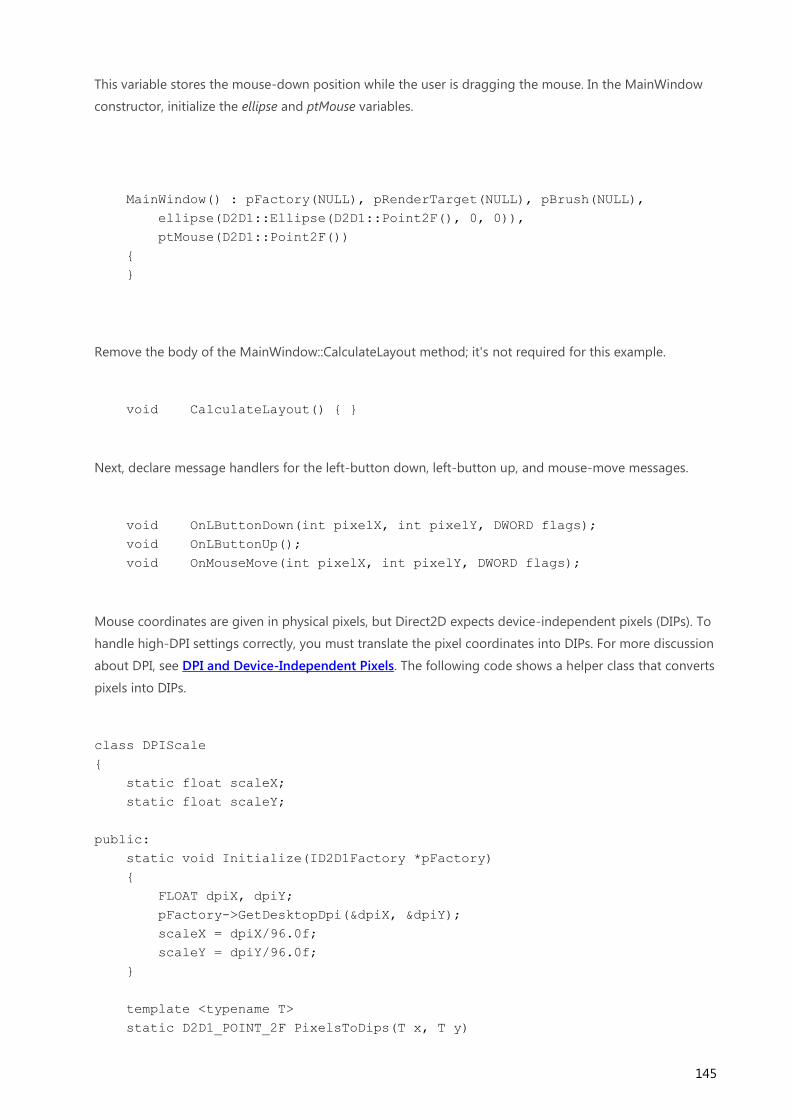
145
This variable stores the mouse-down position while the user is dragging the mouse. In the MainWindow
constructor, initialize the ellipse and ptMouse variables.
MainWindow() : pFactory(NULL), pRenderTarget(NULL), pBrush(NULL),
ellipse(D2D1::Ellipse(D2D1::Point2F(), 0, 0)),
ptMouse(D2D1::Point2F())
{
}
Remove the body of the MainWindow::CalculateLayout method; it's not required for this example.
void CalculateLayout() { }
Next, declare message handlers for the left-button down, left-button up, and mouse-move messages.
void OnLButtonDown(int pixelX, int pixelY, DWORD flags);
void OnLButtonUp();
void OnMouseMove(int pixelX, int pixelY, DWORD flags);
Mouse coordinates are given in physical pixels, but Direct2D expects device-independent pixels (DIPs). To
handle high-DPI settings correctly, you must translate the pixel coordinates into DIPs. For more discussion
about DPI, see DPI and Device-Independent Pixels. The following code shows a helper class that converts
pixels into DIPs.
class DPIScale
{
static float scaleX;
static float scaleY;
public:
static void Initialize(ID2D1Factory *pFactory)
{
FLOAT dpiX, dpiY;
pFactory->GetDesktopDpi(&dpiX, &dpiY);
scaleX = dpiX/96.0f;
scaleY = dpiY/96.0f;
}
template <typename T>
static D2D1_POINT_2F PixelsToDips(T x, T y)
146
{
return D2D1::Point2F(static_cast<float>(x) / scaleX,
static_cast<float>(y) / scaleY);
}
};
float DPIScale::scaleX = 1.0f;
float DPIScale::scaleY = 1.0f;
Call DPIScale::Initialize in your WM_CREATE handler, after you create the Direct2D factory object.
case WM_CREATE:
if (FAILED(D2D1CreateFactory(
D2D1_FACTORY_TYPE_SINGLE_THREADED, &pFactory)))
{
return -1; // Fail CreateWindowEx.
}
DPIScale::Initialize(pFactory);
return 0;
To get the mouse coordinates in DIPs from the mouse messages, do the following:
1. Use the GET_X_LPARAM and GET_Y_LPARAM macros to get the pixel coordinates. These macros
are defined in WindowsX.h, so remember to include that header in your project.
2. Call DPIScale::PixelsToDipsX and DPIScale::PixelsToDipsY to convert pixels to DIPs.
Now add the message handlers to your window procedure.
case WM_LBUTTONDOWN:
OnLButtonDown(GET_X_LPARAM(lParam), GET_Y_LPARAM(lParam),
(DWORD)wParam);
return 0;
case WM_LBUTTONUP:
OnLButtonUp();
return 0;
case WM_MOUSEMOVE:
OnMouseMove(GET_X_LPARAM(lParam), GET_Y_LPARAM(lParam),
(DWORD)wParam);
return 0;
Finally, implement the message handlers themselves.

147
Left Button Down
For the left-button down message, do the following:
1. Call SetCapture to begin capturing the mouse.
2. Store the position of the mouse click in the ptMouse variable. This position defines the upper left
corner of the bounding box for the ellipse.
3. Reset the ellipse structure.
4. Call InvalidateRect. This function forces the window to be repainted.
void MainWindow::OnLButtonDown(int pixelX, int pixelY, DWORD flags)
{
SetCapture(m_hwnd);
ellipse.point = ptMouse = DPIScale::PixelsToDips(pixelX, pixelY);
ellipse.radiusX = ellipse.radiusY = 1.0f;
InvalidateRect(m_hwnd, NULL, FALSE);
}
Mouse Move
For the mouse-move message, check whether the left mouse button is down. If it is, recalculate the ellipse
and repaint the window. In Direct2D, an ellipse is defined by the center point and x- and y-radii. We want
to draw an ellipse that fits the bounding box defined by the mouse-down point (ptMouse) and the current
cursor position (x, y), so a bit of arithmetic is needed to find the width, height, and position of the ellipse.
The following code recalculates the ellipse and then calls InvalidateRect to repaint the window.
void MainWindow::OnMouseMove(int pixelX, int pixelY, DWORD flags)
{
if (flags & MK_LBUTTON)
{

148
const D2D1_POINT_2F dips = DPIScale::PixelsToDips(pixelX, pixelY);
const float width = (dips.x - ptMouse.x) / 2;
const float height = (dips.y - ptMouse.y) / 2;
const float x1 = ptMouse.x + width;
const float y1 = ptMouse.y + height;
ellipse = D2D1::Ellipse(D2D1::Point2F(x1, y1), width, height);
InvalidateRect(m_hwnd, NULL, FALSE);
}
}
Left Button Up
For the left-button-up message, simply call ReleaseCapture to release the mouse capture.
void MainWindow::OnLButtonUp()
{
ReleaseCapture();
}

149
Miscellaneous Mouse Operations
The previous sections have discussed mouse clicks and mouse movement. Here are some other
operations that can be performed with the mouse.
Dragging UI Elements
If your UI supports dragging of UI elements, there is one other function that you should call in your
mouse-down message handler: DragDetect. The DragDetect function returns TRUE if the user initiates a
mouse gesture that should be interpreted as dragging. The following code shows how to use this
function.
case WM_LBUTTONDOWN:
{
POINT pt = { GET_X_LPARAM(lParam), GET_Y_LPARAM(lParam) };
if (DragDetect(m_hwnd, pt))
{
// Start dragging.
}
}
return 0;
Here's the idea: When a program supports drag and drop, you don't want every mouse click to be
interpreted as a drag. Otherwise, the user might accidentally drag something when he or she simply
meant to click on it (for example, to select it). But if a mouse is particularly sensitive, it can be hard to keep
the mouse perfectly still while clicking. Therefore, Windows defines a drag threshold of a few pixels. When
the user presses the mouse button, it is not considered a drag unless the mouse crosses this threshold.
The DragDetect function tests whether this threshold is reached. If the function returns TRUE, you can
interpret the mouse click as a drag. Otherwise, do not.
Note If DragDetect returns FALSE, Windows suppresses the WM_LBUTTONUP message when the user
releases the mouse button. Therefore, do not call DragDetect unless your program is currently in a mode
that supports dragging. (For example, if a draggable UI element is already selected.) At the end of this
module, we will see a longer code example that uses the DragDetect function.
Confining the Cursor
Sometimes you might want to restrict the cursor to the client area or a portion of the client area. The
ClipCursor function restricts the movement of the cursor to a specified rectangle. This rectangle is given
in screen coordinates, rather than client coordinates, so the point (0, 0) means the upper left corner of the
screen. To translate client coordinates into screen coordinates, call the function ClientToScreen.

150
The following code confines the cursor to the client area of the window.
// Get the window client area.
RECT rc;
GetClientRect(m_hwnd, &rc);
// Convert the client area to screen coordinates.
POINT pt = { rc.left, rc.top };
POINT pt2 = { rc.right, rc.bottom };
ClientToScreen(m_hwnd, &pt);
ClientToScreen(m_hwnd, &pt2);
SetRect(&rc, pt.x, pt.y, pt2.x, pt2.y);
// Confine the cursor.
ClipCursor(&rc);
ClipCursor takes a RECT structure, but ClientToScreen takes a POINT structure. A rectangle is defined by
its top-left and bottom-right points. You can confine the cursor to any rectangular area, including areas
outside the window, but confining the cursor to the client area is a typical way to use the function.
Confining the cursor to a region entirely outside your window would be unusual, and users would
probably perceive it as a bug.
To remove the restriction, call ClipCursor with the value NULL.
ClipCursor(NULL);
Mouse Tracking Events: Hover and Leave
Two other mouse messages are disabled by default, but may be useful for some applications:
WM_MOUSEHOVER: The cursor has hovered over the client area for a fixed period of time.
WM_MOUSELEAVE: The cursor has left the client area.
To enable these messages, call the TrackMouseEvent function.
TRACKMOUSEEVENT tme;
tme.cbSize = sizeof(tme);
tme.hwndTrack = hwnd;
tme.dwFlags = TME_HOVER | TME_LEAVE;
tme.dwHoverTime = HOVER_DEFAULT;
TrackMouseEvent(&tme);

151
The TRACKMOUSEEVENT structure contains the parameters for the function. The dwFlags member of
the structure contains bit flags that specify which tracking messages you are interested in. You can choose
to get both WM_MOUSEHOVER and WM_MOUSELEAVE, as shown here, or just one of the two. The
dwHoverTime member specifies how long the mouse needs to hover before the system generates a
hover message. This value is given in milliseconds. The constant HOVER_DEFAULT means to use the
system default.
After you get one of the messages that you requested, the TrackMouseEvent function resets. You must
call it again to get another tracking message. However, you should wait until the next mouse-move
message before calling TrackMouseEvent again. Otherwise, your window might be flooded with tracking
messages. For example, if the mouse is hovering, the system would continue to generate a stream of
WM_MOUSEHOVER messages while the mouse is stationary. You don't actually want another
WM_MOUSEHOVER message until the mouse moves to another spot and hovers again.
Here is a small helper class that you can use to manage mouse-tracking events.
class MouseTrackEvents
{
bool m_bMouseTracking;
public:
MouseTrackEvents() : m_bMouseTracking(false)
{
}
void OnMouseMove(HWND hwnd)
{
if (!m_bMouseTracking)
{
// Enable mouse tracking.
TRACKMOUSEEVENT tme;
tme.cbSize = sizeof(tme);
tme.hwndTrack = hwnd;
tme.dwFlags = TME_HOVER | TME_LEAVE;
tme.dwHoverTime = HOVER_DEFAULT;
TrackMouseEvent(&tme);
m_bMouseTracking = true;
}
}
void Reset(HWND hwnd)
{
m_bMouseTracking = false;
}
};

152
The next example shows how to use this class in your window procedure.
LRESULT MainWindow::HandleMessage(UINT uMsg, WPARAM wParam, LPARAM lParam)
{
switch (uMsg)
{
case WM_MOUSEMOVE:
mouseTrack.OnMouseMove(m_hwnd); // Start tracking.
// TODO: Handle the mouse-move message.
return 0;
case WM_MOUSELEAVE:
// TODO: Handle the mouse-leave message.
mouseTrack.Reset(m_hwnd);
return 0;
case WM_MOUSEHOVER:
// TODO: Handle the mouse-hover message.
mouseTrack.Reset(m_hwnd);
return 0;
}
return DefWindowProc(m_hwnd, uMsg, wParam, lParam);
}
Mouse tracking events require additional processing by the system, so leave them disabled if you do not
need them.
For completeness, here is a function that queries the system for the default hover timeout.
UINT GetMouseHoverTime()
{
UINT msec;
if (SystemParametersInfo(SPI_GETMOUSEHOVERTIME, 0, &msec, 0))
{
return msec;
}
else
{
return 0;
}
}

153
Mouse Wheel
The following function checks if a mouse wheel is present.
BOOL IsMouseWheelPresent()
{
return (GetSystemMetrics(SM_MOUSEWHEELPRESENT) != 0);
}
If the user rotates the mouse wheel, the window with focus receives a WM_MOUSEWHEEL message. The
lParam parameter of this message contains an integer value called the delta that measures how far the
wheel was rotated. The delta uses arbitrary units, where 120 units is defined as the rotation needed to
perform one "action." Of course, the definition of an action depends on your program. For example, if the
mouse wheel is used to scroll text, each 120 units of rotation would scroll one line of text.
The sign of the delta indicates the direction of rotation:
Positive: Rotate forward, away from the user.
Negative: Rotate backward, toward the user.
The value of the delta is placed in lParam along with some additional flags. Use the
GET_WHEEL_DELTA_WPARAM macro to get the value of the delta.
int delta = GET_WHEEL_DELTA_WPARAM(wParam);
If the mouse wheel has a high resolution, the absolute value of the delta might be less than 120. In that
case, if it makes sense for the action to occur in smaller increments, you can do so. For example, text
could scroll by increments of less than one line. Otherwise, accumulate the total delta until the wheel
rotates enough to perform the action. Store the unused delta in a variable, and when 120 units
accumulate (either positive or negative), perform the action.

154
Keyboard Input
The keyboard is used for several distinct types of input, including:
Character input. Text that the user types into a document or edit box.
Keyboard shortcuts. Key strokes that invoke application functions; for example, CTRL + O to open
a file.
System commands. Key strokes that invoke system functions; for example, ALT + TAB to switch
windows.
When thinking about keyboard input, it is important to remember that a key stroke is not the same as a
character. For example, pressing the A key could result in any of the following characters.
a
A
á (if the keyboard supports combining diacritics)
Further, if the ALT key is held down, pressing the A key produces ALT+A, which the system does not treat
as a character at all, but rather as a system command.
Key Codes
When you press a key, the hardware generates a scan code. Scan codes vary from one keyboard to the
next, and there are separate scan codes for key-up and key-down events. You will almost never care
about scan codes. The keyboard driver translates scan codes into virtual-key codes. Virtual-key codes are
device-independent. Pressing the A key on any keyboard generates the same virtual-key code.
In general, virtual-key codes do not correspond to ASCII codes or any other character-encoding standard.
This is obvious if you think about it, because the same key can generate different characters (a, A, á), and
some keys, such as function keys, do not correspond to any character.
That said, the following virtual-key codes do map to ASCII equivalents:
0 through 9 keys = ASCII '0' – '9' (0x30 – 0x39)
A through Z keys = ASCII 'A' – 'Z' (0x41 – 0x5A)
In some respects this mapping is unfortunate, because you should never think of virtual-key codes as
characters, for the reasons discussed.
The header file WinUser.h defines constants for most of the virtual-key codes. For example, the virtual-key
code for the LEFT ARROW key is VK_LEFT (0x25). For the complete list of virtual-key codes, see Virtual-Key
Codes. No constants are defined for the virtual-key codes that match ASCII values. For example, the
virtual-key code for the A key is 0x41, but there is no constant named VK_A. Instead, just use the numeric
value.

155
Key-Down and Key-Up Messages
When you press a key, the window that has keyboard focus receives one of the following messages.
WM_SYSKEYDOWN
WM_KEYDOWN
The WM_SYSKEYDOWN message indicates a system key, which is a key stroke that invokes a system
command. There are two types of system key:
ALT + any key
F10
The F10 key activates the menu bar of a window. Various ALT-key combinations invoke system
commands. For example, ALT + TAB switches to a new window. In addition, if a window has a menu, the
ALT key can be used to activate menu items. Some ALT key combinations do not do anything.
All other key strokes are considered nonsystem keys and produce the WM_KEYDOWN message. This
includes the function keys other than F10.
When you release a key, the system sends a corresponding key-up message:
WM_KEYUP
WM_SYSKEYUP
If you hold down a key long enough to start the keyboard's repeat feature, the system sends multiple key-
down messages, followed by a single key-up message.
In all four of the keyboard messages discussed so far, the wParam parameter contains the virtual-key
code of the key. The lParam parameter contains some miscellaneous information packed into 32 bits. You
typically do not need the information in lParam. One flag that might be useful is bit 30, the "previous key
state" flag, which is set to 1 for repeated key-down messages.
As the name implies, system key strokes are primarily intended for use by the operating system. If you
intercept the WM_SYSKEYDOWN message, call DefWindowProc afterward. Otherwise, you will block the
operating system from handling the command.
Character Messages
Key strokes are converted into characters by the TranslateMessage function, which we first saw in
Module 1. This function examines key-down messages and translates them into characters. For each
character that is produced, the TranslateMessage function puts a WM_CHAR or WM_SYSCHAR
message on the message queue of the window. The wParam parameter of the message contains the UTF-
16 character.

156
As you might guess, WM_CHAR messages are generated from WM_KEYDOWN messages, while
WM_SYSCHAR messages are generated from WM_SYSKEYDOWN messages. For example, suppose the
user presses the SHIFT key followed by the A key. Assuming a standard keyboard layout, you would get
the following sequence of messages:
WM_KEYDOWN: SHIFT
WM_KEYDOWN: A
WM_CHAR: 'A'
On the other hand, the combination ALT + P would generate:
WM_SYSKEYDOWN: VK_MENU
WM_SYSKEYDOWN: 0x50
WM_SYSCHAR: 'p'
WM_SYSKEYUP: 0x50
WM_KEYUP: VK_MENU
(The virtual-key code for the ALT key is named VK_MENU for historical reasons.)
The WM_SYSCHAR message indicates a system character. As with WM_SYSKEYDOWN, you should
generally pass this message directly to DefWindowProc. Otherwise, you may interfere with standard
system commands. In particular, do not treat WM_SYSCHAR as text that the user has typed.
The WM_CHAR message is what you normally think of as character input. The data type for the character
is wchar_t, representing a UTF-16 Unicode character. Character input can include characters outside the
ASCII range, especially with keyboard layouts that are commonly used outside of the United States. You
can try different keyboard layouts by installing a regional keyboard and then using the On-Screen
Keyboard feature.
Users can also install an Input Method Editor (IME) to enter complex scripts, such as Japanese characters,
with a standard keyboard. For example, using a Japanese IME to enter the katakana character カ (ka), you
might get the following messages:
WM_KEYDOWN: VK_PROCESSKEY (the IME PROCESS key)
WM_KEYUP: 0x4B
WM_KEYDOWN: VK_PROCESSKEY
WM_KEYUP: 0x41
WM_KEYDOWN: VK_PROCESSKEY
WM_CHAR: カ
WM_KEYUP: VK_RETURN
Some CTRL key combinations are translated into ASCII control characters. For example, CTRL+A is
translated to the ASCII ctrl-A (SOH) character (ASCII value 0x01). For text input, you should generally filter
out the control characters. Also, avoid using WM_CHAR to implement keyboard shortcuts. Instead, use

157
WM_KEYDOWN messages; or even better, use an accelerator table. Accelerator tables are described in
the next topic, Accelerator Tables.
The following code displays the main keyboard messages in the debugger. Try playing with different
keystroke combinations and see what messages are generated.
LRESULT CALLBACK WindowProc(HWND hwnd, UINT uMsg, WPARAM wParam, LPARAM
lParam)
{
wchar_t msg[32];
switch (uMsg)
{
case WM_SYSKEYDOWN:
swprintf_s(msg, L"WM_SYSKEYDOWN: 0x%x\n", wParam);
OutputDebugString(msg);
break;
case WM_SYSCHAR:
swprintf_s(msg, L"WM_SYSCHAR: %c\n", (wchar_t)wParam);
OutputDebugString(msg);
break;
case WM_SYSKEYUP:
swprintf_s(msg, L"WM_SYSKEYUP: 0x%x\n", wParam);
OutputDebugString(msg);
break;
case WM_KEYDOWN:
swprintf_s(msg, L"WM_KEYDOWN: 0x%x\n", wParam);
OutputDebugString(msg);
break;
case WM_KEYUP:
swprintf_s(msg, L"WM_KEYUP: 0x%x\n", wParam);
OutputDebugString(msg);
break;
case WM_CHAR:
swprintf_s(msg, L"WM_CHAR: %c\n", (wchar_t)wParam);
OutputDebugString(msg);
break;
/* Handle other messages (not shown) */
}
return DefWindowProc(m_hwnd, uMsg, wParam, lParam);
}

158
Miscellaneous Keyboard Messages
Some other keyboard messages can safely be ignored by most applications.
The WM_DEADCHAR message is sent for a combining key, such as a diacritic. For example, on a
Spanish language keyboard, typing accent (') followed by E produces the character é. The
WM_DEADCHAR is sent for the accent character.
The WM_UNICHAR message is obsolete. It enables ANSI programs to receive Unicode character
input.
The WM_IME_CHAR character is sent when an IME translates a keystroke sequence into
characters. It is sent in addition to the usual WM_CHAR message.
Keyboard State
The keyboard messages are event-driven. That is, you get a message when something interesting
happens, such as a key press, and the message tells you what just happened. But you can also test the
state of a key at any time, by calling the GetKeyState function.
For example, consider how would you detect the combination of left mouse click + ALT key. You could
track the state of the ALT key by listening for key-stroke messages and storing a flag, but GetKeyState
saves you the trouble. When you receive the WM_LBUTTONDOWN message, just call GetKeyState as
follows:
if (GetKeyState(VK_MENU) & 0x8000))
{
// ALT key is down.
}
The GetKeyState message takes a virtual-key code as input and returns a set of bit flags (actually just two
flags). The value 0x8000 contains the bit flag that tests whether the key is currently pressed.
Most keyboards have two ALT keys, left and right. The previous example tests whether either of them of
pressed. You can also use GetKeyState to distinguish between the left and right instances of the ALT,
SHIFT, or CTRL keys. For example, the following code tests if the right ALT key is pressed.
if (GetKeyState(VK_RMENU) & 0x8000))
{
// Right ALT key is down.
}
159
The GetKeyState function is interesting because it reports a virtual keyboard state. This virtual state is
based on the contents of your message queue, and gets updated as you remove messages from the
queue. As your program processes window messages, GetKeyState gives you a snapshot of the keyboard
at the time that each message was queued. For example, if the last message on the queue was
WM_LBUTTONDOWN, GetKeyState reports the keyboard state at the moment when the user clicked
the mouse button.
Because GetKeyState is based on your message queue, it also ignores keyboard input that was sent to
another program. If the user switches to another program, any key presses that are sent to that program
are ignored by GetKeyState. If you really want to know the immediate physical state of the keyboard,
there is a function for that: GetAsyncKeyState. For most UI code, however, the correct function is
GetKeyState.

160
Accelerator Tables
Applications often define keyboard shortcuts, such as CTRL+O for the File Open command. You could
implement keyboard shortcuts by handling individual WM_KEYDOWN messages, but accelerator tables
provide a better solution that:
Requires less coding.
Consolidates all of your shortcuts into one data file.
Supports localization into other languages.
Enables shortcuts and menu commands to use the same application logic.
An accelerator table is a data resource that maps keyboard combinations, such as CTRL+O, to application
commands. Before we see how to use an accelerator table, we'll need a quick introduction to resources. A
resource is a data blob that is built into an application binary (EXE or DLL). Resources store data that are
needed by the application, such as menus, cursors, icons, images, text strings, or any custom application
data. The application loads the resource data from the binary at run time. To include resources in a binary,
do the following:
1. Create a resource definition (.rc) file. This file defines the types of resources and their identifiers.
The resource definition file may include references to other files. For example, an icon resource is
declared in the .rc file, but the icon image is stored in a separate file.
2. Use the Microsoft Windows Resource Compiler (RC) to compile the resource definition file into a
compiled resource (.res) file. The RC compiler is provided with Visual Studio and also the Windows
SDK.
3. Link the compiled resource file to the binary file.
These steps are roughly equivalent to the compile/link process for code files. Visual Studio provides a set
of resource editors that make it easy to create and modify resources. (These tools are not available in the
Express editions of Visual Studio.) But an .rc file is simply a text file, and the syntax is documented on
MSDN, so it is possible to create an .rc file using any text editor. For more information, see About
Resource Files.
Defining an Accelerator Table
An accelerator table is a table of keyboard shortcuts. Each shortcut is defined by:
A numeric identifier. This number identifies the application command that will be invoked by the
shortcut.
The ASCII character or virtual-key code of the shortcut.
Optional modifier keys: ALT, SHIFT, or CTRL.
The accelerator table itself has a numeric identifier, which identifies the table in the list of application
resources. Let's create an accelerator table for a simple drawing program. This program will have two

161
modes, draw mode and selection mode. In draw mode, the user can draw shapes. In selection mode, the
user can select shapes. For this program, we would like to define the following keyboard shortcuts.
Shortcut Command
CTRL+M Toggle between modes.
F1 Switch to draw mode.
F2 Switch to selection mode.
First, define numeric identifiers for the table and for the application commands. These values are arbitrary.
You can assign symbolic constants for the identifiers by defining them in a header file. For example:
#define IDR_ACCEL1 101
#define ID_TOGGLE_MODE 40002
#define ID_DRAW_MODE 40003
#define ID_SELECT_MODE 40004
In this example, the value IDR_ACCEL1 identifies the accelerator table, and the next three constants define
the application commands. By convention, a header file that defines resource constants is often named
resource.h. The next listing shows the resource definition file.
#include "resource.h"
IDR_ACCEL1 ACCELERATORS
{
0x4D, ID_TOGGLE_MODE, VIRTKEY, CONTROL // ctrl-M
0x70, ID_DRAW_MODE, VIRTKEY // F1
0x71, ID_SELECT_MODE, VIRTKEY // F2
}
The accelerator shortcuts are defined within the curly braces. Each shortcut contains the following entries.
The virtual-key code or ASCII character that invokes the shortcut.
The application command. Notice that symbolic constants are used in the example. The resource
definition file includes resource.h, where these constants are defined.
The keyword VIRTKEY means the first entry is a virtual-key code. The other option is to use ASCII
characters.
162
Optional modifiers: ALT, CONTROL, or SHIFT.
If you use ASCII characters for shortcuts, then a lowercase character will be a different shortcut than an
uppercase character. (For example, typing 'a' might invoke a different command than typing 'A'.) That
might confuse users, so it is generally better to use virtual-key codes, rather than ASCII characters, for
shortcuts.
Loading the Accelerator Table
The resource for the accelerator table must be loaded before the program can use it. To load an
accelerator table, call the LoadAccelerators function.
HACCEL hAccel = LoadAccelerators(hInstance, MAKEINTRESOURCE(IDR_ACCEL1));
Call this function before you enter the message loop. The first parameter is the handle to the module.
(This parameter is passed to your WinMain function. For details, see WinMain: The Application Entry
Point.) The second parameter is the resource identifier. The function returns a handle to the resource.
Recall that a handle is an opaque type that refers to an object managed by the system. If the function
fails, it returns NULL.
You can release an accelerator table by calling DestroyAcceleratorTable. However, the system
automatically releases the table when the program exits, so you only need to call this function if you are
replacing one table with another. There is an interesting example of this in the topic Creating User
Editable Accelerators.
Translating Key Strokes into Commands
An accelerator table works by translating key strokes into WM_COMMAND messages. The wParam
parameter of WM_COMMAND contains the numeric identifier of the command. For example, using the
table shown previously, the key stroke CTRL+M is translated into a WM_COMMAND message with the
value ID_TOGGLE_MODE. To make this happen, change your message loop to the following:
MSG msg;
while (GetMessage(&msg, NULL, 0, 0))
{
if (!TranslateAccelerator(win.Window(), hAccel, &msg))
{
TranslateMessage(&msg);
DispatchMessage(&msg);
}
}

163
This code adds a call to the TranslateAccelerator function inside the message loop. The
TranslateAccelerator function examines each window message, looking for key-down messages. If the
user presses one of the key combinations listed in the accelerator table, TranslateAccelerator sends a
WM_COMMAND message to the window. The function sends WM_COMMAND by directly invoking the
window procedure. When TranslateAccelerator successfully translates a key stroke, the function returns a
non-zero value, which means you should skip the normal processing for the message. Otherwise,
TranslateAccelerator returns zero. In that case, pass the window message to TranslateMessage and
DispatchMessage, as normal.
Here is how the drawing program might handle the WM_COMMAND message:
case WM_COMMAND:
switch (LOWORD(wParam))
{
case ID_DRAW_MODE:
SetMode(DrawMode);
break;
case ID_SELECT_MODE:
SetMode(SelectMode);
break;
case ID_TOGGLE_MODE:
if (mode == DrawMode)
{
SetMode(SelectMode);
}
else
{
SetMode(DrawMode);
}
break;
}
return 0;
This code assumes that SetMode is a function defined by the application to switch between the two
modes. The details of how you would handle each command obviously depend on your program.

164
Setting the Cursor Image
The cursor is the small image that shows the location of the mouse or other pointing device. Many
applications change the cursor image to give feedback to the user. Although it is not required, it adds a
nice bit of polish to your application.
Windows provides a set of standard cursor images, called system cursors. These include the arrow, the
hand, the I-beam, the hourglass (which is now a spinning circle), and others. This section describes how to
use the system cursors. For more advanced tasks, such as creating custom cursors, see Cursors.
You can associate a cursor with a window class by setting the hCursor member of the WNDCLASS or
WNDCLASSEX structure. Otherwise, the default cursor is the arrow. When the mouse moves over a
window, the window receives a WM_SETCURSOR message (unless another window has captured the
mouse). At this point, one of the following events occurs:
The application sets the cursor and the window procedure returns TRUE.
The application does nothing and passes WM_SETCURSOR to DefWindowProc.
To set the cursor, a program does the following:
1. Calls LoadCursor to load the cursor into memory. This function returns a handle to the cursor.
2. Calls SetCursor and passes in the cursor handle.
Otherwise, if the application passes WM_SETCURSOR to DefWindowProc, the DefWindowProc function
uses the following algorithm to set the cursor image:
1. If the window has a parent, forward the WM_SETCURSOR message to the parent to handle.
2. Otherwise, if the window has a class cursor, set the cursor to the class cursor.
3. If there is no class cursor, set the cursor to the arrow cursor.
The LoadCursor function can load either a custom cursor from a resource, or one of the system cursors.
The following example shows how to set the cursor to the system hand cursor.
hCursor = LoadCursor(NULL, cursor);
SetCursor(hCursor);
If you change the cursor, the cursor image resets on the next mouse move, unless you intercept the
WM_SETCURSOR message and set the cursor again. The following code shows how to handle
WM_SETCURSOR.
165
case WM_SETCURSOR:
if (LOWORD(lParam) == HTCLIENT)
{
SetCursor(hCursor);
return TRUE;
}
break;
This code first checks the lower 16 bits of lParam. If LOWORD(lParam) equals HTCLIENT, it means the
cursor is over the client area of the window. Otherwise, the cursor is over the nonclient area. Typically, you
should only set the cursor for the client area, and let Windows set the cursor for the nonclient area.

166
User Input: Extended Example
Let's put together everything that we have learned about user input to create a simple drawing program.
Here is a screen shot of the program:
Screen shot of the Drawing program
The user can draw ellipses in several different colors, and select, move, or delete ellipses. To keep the UI
simple, the program does not allow the user to select the ellipse colors. Instead, the program
automatically cycles through a predefined list of colors. The program does not support any other shapes
besides ellipses. Obviously, this program will not win any awards for graphics software, but it is still a
useful example to learn from. You can download the complete source code from Simple Drawing Sample.
This section will just cover some of the highlights.
Ellipses are represented in the program by a structure that contains the ellipse data (D2D1_ELLIPSE) and
the color (D2D1_COLOR_F). The structure also defines two methods: a method to draw the ellipse, and a
method to perform hit testing.
struct MyEllipse
{
D2D1_ELLIPSE ellipse;
D2D1_COLOR_F color;
void Draw(ID2D1RenderTarget *pRT, ID2D1SolidColorBrush *pBrush)
{
pBrush->SetColor(color);

167
pRT->FillEllipse(ellipse, pBrush);
pBrush->SetColor(D2D1::ColorF(D2D1::ColorF::Black));
pRT->DrawEllipse(ellipse, pBrush, 1.0f);
}
BOOL HitTest(float x, float y)
{
const float a = ellipse.radiusX;
const float b = ellipse.radiusY;
const float x1 = x - ellipse.point.x;
const float y1 = y - ellipse.point.y;
const float d = ((x1 * x1) / (a * a)) + ((y1 * y1) / (b * b));
return d <= 1.0f;
}
};
The program uses the same solid-color brush to draw the fill and outline for every ellipse, changing the
color as needed. In Direct2D, changing the color of a solid-color brush is an efficient operation, so the
solid-color brush object supports a SetColor method.
The ellipses are stored in an STL list container:
list<shared_ptr<MyEllipse>> ellipses;
Note shared_ptr is a smart-pointer class that was added to C++ in TR1 and formalized in C++0x. Visual
Studio 2010 adds support for shared_ptr and other C++0x features. For more information, see Exploring
New C++ and MFC Features in Visual Studio 2010 in MSDN Magazine.
The program has three modes:
Draw mode. The user can draw new ellipses.
Selection mode. The user can select an ellipse.
Drag mode. The user can drag a selected ellipse.
The user can switch between draw mode and selection mode, by using the same keyboard shortcuts
described in Accelerator Tables. From selection mode, the program switches to draw mode if the user
clicks on an ellipse. It switches back to selection mode when the user releases the mouse button. The
current selection is stored as an iterator into the list of ellipses. The helper method
MainWindow::Selection returns a pointer to the selected ellipse, or the value nullptr if there is no
selection.

168
list<shared_ptr<MyEllipse>>::iterator selection;
shared_ptr<MyEllipse> Selection()
{
if (selection == ellipses.end())
{
return nullptr;
}
else
{
return (*selection);
}
}
void ClearSelection() { selection = ellipses.end(); }
The following table summarizes the effects of mouse input in each of the three modes.
Mouse Input Draw Mode Selection Mode Drag Mode
Left button
down
Set mouse capture and
start drawing a new
ellipse.
Release the current selection and perform a
hit test. If an ellipse is hit, capture the cursor,
select the ellipse, and switch to drag mode.
No action.
Mouse move If the left button is
down, resize the ellipse. No action.
Move the
selected ellipse.
Left button up Stop drawing the
ellipse. No action.
Switch to
selection mode.
The following method in the MainWindow class handles WM_LBUTTONDOWN messages.
void MainWindow::OnLButtonDown(int pixelX, int pixelY, DWORD flags)
{
const float dipX = DPIScale::PixelsToDipsX(pixelX);
const float dipY = DPIScale::PixelsToDipsY(pixelY);
if (mode == DrawMode)
{
POINT pt = { pixelX, pixelY };
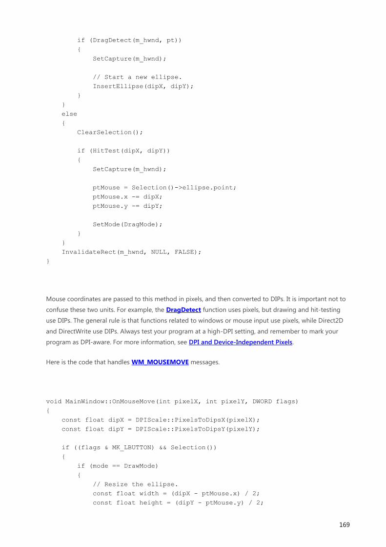
169
if (DragDetect(m_hwnd, pt))
{
SetCapture(m_hwnd);
// Start a new ellipse.
InsertEllipse(dipX, dipY);
}
}
else
{
ClearSelection();
if (HitTest(dipX, dipY))
{
SetCapture(m_hwnd);
ptMouse = Selection()->ellipse.point;
ptMouse.x -= dipX;
ptMouse.y -= dipY;
SetMode(DragMode);
}
}
InvalidateRect(m_hwnd, NULL, FALSE);
}
Mouse coordinates are passed to this method in pixels, and then converted to DIPs. It is important not to
confuse these two units. For example, the DragDetect function uses pixels, but drawing and hit-testing
use DIPs. The general rule is that functions related to windows or mouse input use pixels, while Direct2D
and DirectWrite use DIPs. Always test your program at a high-DPI setting, and remember to mark your
program as DPI-aware. For more information, see DPI and Device-Independent Pixels.
Here is the code that handles WM_MOUSEMOVE messages.
void MainWindow::OnMouseMove(int pixelX, int pixelY, DWORD flags)
{
const float dipX = DPIScale::PixelsToDipsX(pixelX);
const float dipY = DPIScale::PixelsToDipsY(pixelY);
if ((flags & MK_LBUTTON) && Selection())
{
if (mode == DrawMode)
{
// Resize the ellipse.
const float width = (dipX - ptMouse.x) / 2;
const float height = (dipY - ptMouse.y) / 2;

170
const float x1 = ptMouse.x + width;
const float y1 = ptMouse.y + height;
Selection()->ellipse = D2D1::Ellipse(D2D1::Point2F(x1, y1),
width, height);
}
else if (mode == DragMode)
{
// Move the ellipse.
Selection()->ellipse.point.x = dipX + ptMouse.x;
Selection()->ellipse.point.y = dipY + ptMouse.y;
}
InvalidateRect(m_hwnd, NULL, FALSE);
}
}
The logic to resize an ellipse was described previously, in the section Example: Drawing Circles. Also note
the call to InvalidateRect, which ensures that the window is repainted. The following code handles
WM_LBUTTONUP messages.
void MainWindow::OnLButtonUp()
{
if ((mode == DrawMode) && Selection())
{
ClearSelection();
InvalidateRect(m_hwnd, NULL, FALSE);
}
else if (mode == DragMode)
{
SetMode(SelectMode);
}
ReleaseCapture();
}
As you can see, the message handlers for mouse input all have branching code, depending on the current
mode. That is an acceptable design for this relatively simple program, but it could quickly become too
complicated if new modes are added. For a larger program, a model-view-controller (MVC) architecture
might be a better design. In this type of architecture, the controller, which handles user input, is separated
from the model, which manages application data.
When the program switches modes, the cursor changes to give feedback to the user.

171
void MainWindow::SetMode(Mode m)
{
mode = m;
// Update the cursor
LPWSTR cursor;
switch (mode)
{
case DrawMode:
cursor = IDC_CROSS;
break;
case SelectMode:
cursor = IDC_HAND;
break;
case DragMode:
cursor = IDC_SIZEALL;
break;
}
hCursor = LoadCursor(NULL, cursor);
SetCursor(hCursor);
}
And finally, remember to set the cursor when the window receives a WM_SETCURSOR message:
case WM_SETCURSOR:
if (LOWORD(lParam) == HTCLIENT)
{
SetCursor(hCursor);
return TRUE;
}
break;
Summary
In this module, you learned how to handle mouse and keyboard input; how to define keyboard short cuts;
and how to update the cursor image to reflect the current state of the program.