Embed Size (px)
Citation preview

LC motors
Installation and commissioning
Part number: 5380 en - 2017.06 / b
Liquid-cooled 3-phase induction motorsIE3 Premium efficiency

2 LC motors installation and commissioning5380 en - 2017.06 / b
GENERAL WARNING
These symbols appear in this document whenever it is important to take special precautions during installation, operation, maintenance or servicing of the motors.
It is essential that electric motors are installed by experienced, qualified and authorised personnel.
In accordance with the main requirements of EU Directives, the safety of people, animals and property should be ensured when fitting the motors into machines.
Particular attention must be given to equipotential ground or earthing connections.
The noise level of the machines, measured under standard conditions, conforms to the requirements of the standard.
The following preliminary precautions must be taken before working on any stationary device:• Mains voltage disconnected and no residual voltage present• Careful examination of the causes of the stoppage (jammed transmission - loss of phase - cut - out
due to thermal protection - lack of lubrication, etc.)

3LC motors installation and commissioning5380 en - 2017.06 / b
Dear Customer,
You have just acquired a LEROY-SOMER motor.
This motor benefits from the experience of one of the largest manufacturers in the world, using state-of-the-art technology in automation, specially selected materials and rigorous quality control. As a result, the regulatory authorities awarded our motor factories ISO 9001 - Edition 2008 international certification from the DNV. Similarly, our environmental approach enabled us to achieve ISO 14001:2004 certification.
We thank you for making this choice, and would ask you to read the contents of this manual.
By observing a few essential rules, you will ensure problem-free operation for many years.
LEROY-SOMER MOTORSCE conformityOur motors conform to standard EN 60034 (IEC 34), and to the 2006/95/EC Low Voltage Directive modified by the 2006/42/EC Machine Directive, which is demonstrated by their marking with the symbol
NOTE:LEROY-SOMER reserves the right to modify the characteristics of its products at any time in order to incorporate the latest technological developments. The information contained in this document is therefore liable to be changed without notice.Copyright 2016: MOTEURS LEROY-SOMERThis document is the property of LEROY-SOMER.It may not be reproduced in any form without prior authorisation.All brands and models have been registered and patents applied for.
Constructions Électriques de Beaucourt (CEB) Rue de Dampierre 90500 BEAUCOURT
T +33 (0)3 84 36 40 40 F +33 (0)3 84 36 40 44
N/Ref: Q0l T 400 rev B
Beaucourt, November 19th, 2015
DECLARATION CE OF CONFORMITY AND INCORPORATION
Motor types FLS, PLS, FLSES, PLSES, SLSHR, LC,
FLSHR, FLSAR, FLSHT, FLSB Frame size 280 à 560mm
We, Constructions Electriques de Beaucourt {CEB), a company of Emerson/ Leroy-Somer group, declare, under our
sole responsability, that the following products :
Asynchronous motors FLS, PLS, FLSES, PLSES, SLSHR, LC, FLSHR, FLSAR, FLSHT, FLSB series Frame size 280 to 560 mm
Comply with :
• European and international standards : • The Low Voltage Directive : • The ErP Directive :
IEC-EN 60034 / IEC-EN 60072 / IEC-EN 60529 2006/95/CE 2009/125/CE and its application rules {CE) 640/2009 for the concerned motors
This conformity permits the use of these ranges of products in machines subject to the application of the Machinery Directive 2006/42/CE, provided that they are integrated or incorporated and/or assembled in accordance with, amongst others, the regulations of standard EN 60204 "Electrical Equipment for Machinery" and the Electromagnetic Compatibility Directive 2004/108/CE.
The above defined products shall not be put into service until the machines in which they are incorporated have been declared compliant with related applicable directives.
The equlpment Installation shall comply with ail regulations, decrees, ordinances, directives, application notes, standards, state of the art practices as well as any other document relative to their installation. CONSTRUCTIONS ELECTRIQUES DE BEAUCOURT {CEB) shall not be held responsible for failure to comply with these ru les.
The motors supplied through adapted electronic converters and/or command or monitoring electronic devices, shall be installed by a qualified professional responslble of compliance to all installation rules. This installer shall also be responsible for the conformity with the local EMC rules in force in the considered country where the product is being installed, as well as for the respect of values stamped on motor rating plate(s); the Instruction manual, the installation Instructions, the maintenance manuals and/or any other document supplied by the manufacturer.
Year of CE marking : 2011
\ J Technical management: /) T. PERA 1
�� Constructions Electriques de Beaucourt (CEB) - Siège social : Rue de Dampierre - 90500 BEAUCOURT
Société par Actions Simplifiées au capital de 8 004 000 € - RCS Belfort 321 253 916
Page 1 sur 1
4
CONTENTS
LC motors installation and commissioning5380 en - 2017.06 / b
CONTENTS
1 - RECEIPT .............................................................. 51.1 - Identification ........................................................... 51.2 - Storage ...................................................................6
2 - INSTALLATION RECOMMENDATIONS .............. 62.1 - Checking the insulation ...........................................62.2 - Checking the motor terminal box ............................72.3 - Mounting the motor .................................................72.4 - Cooling circuit .........................................................72.5 - Coupling .................................................................82.6 - Motor control and protection .................................102.7 - Electrical connections ........................................... 142.8 - Connecting the cooling system ............................212.9 - Filling ....................................................................22
3 - START-UP .......................................................... 223.1 - Initial start-up ........................................................223.2 - Operation ..............................................................22
4 - CHECKS AFTER START-UP .............................. 234.1 - Checking the cooling system .................................234.2 - Mechanical checks ...............................................234.3 - Cleaning ................................................................234.4 - Draining condensation ..........................................234.5 - Greasing ...............................................................234.6 - Checking the end shields ......................................24
5 – PREVENTIVE MAINTENANCE ......................... 25
6 - TROUBLESHOOTING GUIDE ............................ 26
7 - POSITION OF LIFTING RINGS .......................... 27
8 - SPARE PARTS.................................................... 28
9 - RECYCLING ........................................................ 28
10 - CROSS-SECTIONAL VIEWS ........................... 29
INDEX
Adjustment ...........................................................................9Alarms - early warning ........................................................ 12
Balancing .............................................................................8Belts ...................................................................................10Built-in thermal protection .................................................. 11
Cable glands ................................................................ 14 - 15Cables: cross-section .................................................. 16 - 18Capacitors .......................................................................... 11Connection diagrams .........................................................19Connection .........................................................................20Cooling circuit .......................................................................7Coupling sleeve ....................................................................9Coupling ...............................................................................8
Digistart .............................................................................. 11 Direction of rotation ............................................................20Draining condensation .......................................................23
Earth terminal .....................................................................20Earth ................................................................................... 11Electrical connections ........................................................14End shields .................................................................. 21 - 24European directives ..............................................................5
Frequency inverter.......................................... 11 - 13 - 17 - 18
Greasing - Grease nipples ............................................. 6 - 24
Identification ........................................................................5Inertia flywheel .....................................................................9Insulation ..............................................................................6
Lifting ring .......................................................................... 27Logos ....................................................................................5Lubrication ..........................................................................23
Mounting the motor ...............................................................7
Nameplate ............................................................................5
Power supply ......................................................................16Protection devices .............................................................. 11Pulleys ................................................................................10
Space heaters .................................................................... 12Spare parts .........................................................................28Start-up ..............................................................................10Storage .................................................................................6
Terminal block tightening torques .......................................20Terminal box .......................................................................14Tolerances ............................................................................9Troubleshooting .................................................................24
Water leakage detector ...................................................... 13

5LC motors installation and commissioning5380 en - 2017.06 / b
RECEIPT
1 - RECEIPTOn receipt of your motor, check that it has not suffered any damage in transit. If there are obvious signs of knocks, contact the carrier (you may able to claim on their insurance) and after a visual check, turn the motor by hand to detect any malfunction.
1.1 - IdentificationAs soon as you receive the motor, check that the nameplate on the machine conforms to your order.
Definition of symbols used on nameplates:
Legal mark of conformity to the requirements of European Directives
If the motor is fitted with winding sensors:• TP111B (1 set of sensors)• TP121B (2 sets of sensors)
IEC
600
34-1
- M
AD
E IN
FR
AN
CE
MOT. N° kg
V Hz kW cos ϕAmin-1S d/h SFIns cl. °C %
DENDE
IPIK
hh
gg
m
%%
IE
IEC
600
34-1
- M
AD
E IN
FR
AN
CE
MOT. N° kg
V
T/Tn%Hz
Hz kW cos ϕAminInverter settings
-1
min-1
S d/h SFIns cl. °C %
DENDE
IPIK
hh
gg
m
Motor performance
min. Fsw (kHz) :Nmax ( ) :
3
1 6100 1.0F40
LC 450 LA 4
A
H
2016 41006326 C3 80 3000 55 1000
IM 1001
IM 1001
6324 C3
Polyrex EM 103Min water �ow = 70 l/minMax water temp = 38°C Max pressure = 5 bars
Min water �ow = 70 l/minMax water temp = 38°C Max pressure = 5 bars
400690380415460
5050505060
14911491149014921788
10001000100010001000
1665 961173916231448
0.890.890.900.880.89
97.4
97.4
97.472 3700 08
74893200XM01
3
6326 C3 806324 C3 72 3700
3000
F40 9
0.89
LC 450 LA 43
32610
2016 410055 1000
Polyrex EM 103
400
10010
10017
10025
100 8350 60
5787
50 1491 1000 1800
08
74893200XM01
Modèle de marquage moteurs LCLogo EMERSON / LSEtabli par F. Boisaubert
Le 19/11/2015
Mot
eurs
Ler
oy-S
omer
Bd
Mar
celli
n Le
roy
CS1
0015
1691
5 A
ngou
lêm
e C
edex
9 -
Fran
ce
Mot
eurs
Ler
oy-S
omer
Bd
Mar
celli
n Le
roy
CS1
0015
1691
5 A
ngou
lêm
e C
edex
9 -
Fran
ce
MOT 3 ~ : 3-phase A.C. motor LC : Series 450 : Frame size LA : Housing symbol 4 : Number of poles
Motor no.
74893200 : Motor batch number X : Year of production M : Month of production 01 : Batch number IE3 :Efficiencyclass 97.4% :Efficiencyat4/4load
IP55 IK08 : Degree of protectionIns cl. F : Insulation class F40°C : Ambient operating
temperatureS1 : Duty - Operating factorkg : WeightV : Supply voltageHz : Supply frequencymin-1 : Revolutions per minute (rpm)kW : Rated output powercos ϕ : Power factorA : Rated currentΔ : Delta connectionY : Star connection
Min Water Flow (l/mn) Max Water Temp (°C) Max pressure (bars)
BearingsDE : Drive endNDE g : Amount of grease at each
regreasing (in g)h : Regreasing interval (in hours)POLYREX EM103 : Type of grease
A : Vibration level
H : Balancing mode
Please quote when ordering spare parts
Drive power supply plate:Inverter settings : Values required for setting the frequency inverterMotor performance : Torque available at the motor shaft expressed as a % of the rated torque at the frequencies indicated on the plateMin. Fsw (kHz) : Minimum acceptable switching frequency for the motorNmax (min-1) : Maximum acceptable mechanical speed for the motor
IEC
600
34-1
- M
AD
E IN
FR
AN
CE
MOT. N° kg
V Hz kW cos ϕAmin-1S d/h SFIns cl. °C %
DENDE
IPIK
hh
gg
m
%%
IE
IEC
600
34-1
- M
AD
E IN
FR
AN
CE
MOT. N° kg
V
T/Tn%Hz
Hz kW cos ϕAminInverter settings
-1
min-1
S d/h SFIns cl. °C %
DENDE
IPIK
hh
gg
m
Motor performance
min. Fsw (kHz) :Nmax ( ) :
3
1 6100 1.0F40
LC 450 LA 4
A
H
2016 41006326 C3 80 3000 55 1000
IM 1001
IM 1001
6324 C3
Polyrex EM 103Min water �ow = 70 l/minMax water temp = 38°C Max pressure = 5 bars
Min water �ow = 70 l/minMax water temp = 38°C Max pressure = 5 bars
400690380415460
5050505060
14911491149014921788
10001000100010001000
1665 961173916231448
0.890.890.900.880.89
97.4
97.4
97.472 3700 08
74893200XM01
3
6326 C3 806324 C3 72 3700
3000
F40 9
0.89
LC 450 LA 43
32610
2016 410055 1000
Polyrex EM 103
400
10010
10017
10025
100 8350 60
5787
50 1491 1000 1800
08
74893200XM01
Modèle de marquage moteurs LCLogo EMERSON / LSEtabli par F. Boisaubert
Le 19/11/2015
Mot
eurs
Ler
oy-S
omer
Bd
Mar
celli
n Le
roy
CS1
0015
1691
5 A
ngou
lêm
e C
edex
9 -
Fran
ce
Mot
eurs
Ler
oy-S
omer
Bd
Mar
celli
n Le
roy
CS1
0015
1691
5 A
ngou
lêm
e C
edex
9 -
Fran
ce
Motor performance when powered by a driveMotor performance when powered by the mains supply

6 LC motors installation and commissioning5380 en - 2017.06 / b
INSTALLATION RECOMMENDATIONS
1.2 - StoragePrior to commissioning, motors must be stored in a horizontal position: - Away from humidity (relative humidity < 50%): at higher relative humidity levels the machine insulation can drop very quickly and become virtually non-existent at around 100%. The state of the anti-rust protection on unpainted parts should be monitored.For very long storage periods the motor can be placed in a sealed covering (heat-shrunk plastic, for example) containing sachets of desiccant corresponding to the volume and degree of humidity in the storage location:- Away from frequent significant variations in temperature to avoid the risk of condensation. During storage the drain plugs must be removed to allow condensation to escape (located at the lowest point depending on the operation position).The storage location must be dry and protected from harsh weather conditions and the cold (temperature range should remain between +15°C and +60°C), and be free from vibration, dust and corrosive gases.- If the area is subject to vibration, try to reduce the effect of this vibration by placing the motor on a damping support (rubber plate or similar) and turn the rotor a fraction of a turn every 2 months to prevent the bearing rings from becoming marked.- If there are no vibrations, turn the rotor a fraction of a turn every 3 to 4 months.- Do not remove the rotor locking device (if there are roller bearings).Even if the motor has been stored in the correct conditions, certain checks must be carried out before it is started up:
GreasingGade 2grease
Gade 3grease
Sto
rage
per
iod
Less than 6 months
Less than 1 year
The motor can be commissioned without regreasing
Between 6 monthsand 1 year
Between 1and 2 years
Regrease before commissioning, as described in section 4.5.2
Between 1and 5 years
Between 2and 5 years
Dismantle the bearing- Clean it- Replace the grease completely
More than 5 years
More than 5 years
Change the bearing- Regrease it completely
Refer to the nameplate for the grease used by LEROY-SOMER.
2 - INSTALLATION RECOMMENDATIONS In all cases, compatibility of the motor and its environment must be guaranteed before installation and throughout its service life.
Electric motors are industrial products. They must therefore be installed by
qualified, experienced and authorised personnel. The safety of people, animals and property must be ensured when fitting the motors into machines (please refer to current applicable standards).
2.1 - Checking the insulation
Before starting the motor, it is advisable to check the insulation between phases, and between the phases and earth.
This check is essential if the motor has been stored for longer than 6 months or if it has been kept in a humid atmosphere.This measurement must be carried out using a megohmmeter at 500 volts D.C. (do not use a magnetoelectric system).It is better to carry out an initial test at 30 or 50 volts and, if the insulation is greater than 1 megohm, carry out a second test at 500 volts for 60 seconds between the winding and the earth (at any of the motor terminals). The insulation value must be at least 10 megohms in cold state.If this value cannot be achieved, or if the motor may have been splashed with water or salt spray, or kept for a long period in a very humid place or if it is covered in condensation, it is advisable to dry the motor using the optional space heaters, if fitted (see section 2.6.7.3), or to dry the stator for 24 hours in a drying oven at a temperature of between 110°C and 120°C.If it is not possible to place the motor in a drying oven:- Switch on the motor, with the rotor locked, at 3-phase A.C. voltage reduced to approximately 10% of the rated voltage, for 12 hours (use an induction regulator or a reduction transformer with adjustable outlets).- Or supply the 3 phases in series with a D.C. current, with the voltage at 1 to 2% of the rated voltage. NB: The A.C. current must be monitored using a clamp ammeter, and the D.C. current using a shunt ammeter. This current must not exceed 60% of the rated current.It is advisable to place a thermometer on the motor housing: if the temperature exceeds 70°C, reduce the indicated voltage or current by 5% of the original value for every 10°C difference.While it is drying, all the motor orifices must be open (main terminal box cover, auxiliary terminal box covers, drain holes).
M
Caution: If the high voltage test, carried out at the factory before despatch, needs to be
repeated, it should be performed at half the standard voltage, i.e. 1/2 (2 U+1000 V). Check that the capacitive effect resulting from the high voltage test is eliminated before connecting the terminals to earth.
For any insulation or high voltage test, it is advisable to connect the thermal sensors and/or accessories to earth.

7LC motors installation and commissioning5380 en - 2017.06 / b
INSTALLATION RECOMMENDATIONS
2.2 - Checking the motor terminal boxAfter an extended storage period and after having checked the motor insulation (see section 2.1), the condition of the inside of the main terminal box and the auxiliary terminal boxes should also be checked:- They must be clean, dry and free from dust.- There should be no corrosion on the connection elements.- The seals must be in the correct position.
Otherwise, it will be necessary to recheck the motor's conformance, and some components may even need to be replaced.
2.3 - Mounting the motorThe motor must be mounted in the position specified on the order, on a base which is rigid enough to prevent distortion and vibration.Where the motor feet have six fixing holes, it is preferable to use those which correspond to the standard dimensions for the motor power rating (refer to the LC motors technical catalogue) or, should this not be the case, to those shown at B2 in the diagram below.
Provide easy access to the terminal box, condensation drain plugs, air vents and grease nipples.Use lifting equipment which is compatible with the weight of the motor (indicated on the nameplate).
The lifting rings are designed to lift the motor only and must not be used to lift the whole machine
after the motor has been fitted to it.Note 1: When installing a suspended motor, it is essential to provide protection in case the fixing breaks.Note 2: Never stand on the motor.
2.4 - Cooling circuitLC motors are designed for the following operating conditions:- Ambient temperature: -16°C to +40°C- Altitude: 1000 m maximum
The heat inside the LC motor is dissipated by water circulating in the housing. The water supply system must be installed by the user in accordance with the characteristics indicated on the motor nameplate.
For use at an ambient temperature below +5°C, a glycol-based antifreeze must be added to the
cooling water with an antifreeze to water mix ratio of 40/60.For standard versions, the water inlet temperature is:• 32°C for LC 315 to LC 355 L motors. For temperatures between 32°C and 38°C, depending on the number of poles and the power rating, the motor design can be adapted.• 38°C for LC 355 LK to LC 500 motors.For temperatures above 38°C, please consult Leroy-Somer.The water inlet pressure must not exceed 5 bar.
The water inlet and outlets must not be obstructed as this could cause the motor to overheat.The volume of cooling water and the pressure must comply with the values given in the table below:
Frame size
Min. flow rate
(litre/min)
Max. pressure drop (bar)
Max. pressure
(bar)
Max. water temperature
rise (°C)
315 30 1 5 5
315 LK/355 30 1 5 6
355 LK2-pole 50 1 5 6
355 LK4-6-pole 40 1 5 6
400 45 1 5 6
400 LK/450 70 1 5 6
500 L4-pole 100 1 5 6
500 M6-pole 80 1 5 6
2.4.1 - Cooling water propertiesLC motor housings have a double steel wall in which the cooling water circulates. Good practice must be applied in terms of industrial cooling water, in particular to prevent scaling, corrosion and the build-up of organic matter. The following typical values are given as a guide only:- pH of 7.5 to 8.5- CaCO3 alkalinity: 100 to 400 mg/l- Chloride Cl-: <200 mg/l- Conductivity: 1000 to 1500 µS/cm
The lower the temperature of the water intake, the better the motor cooling.
B2B1

8 LC motors installation and commissioning5380 en - 2017.06 / b
INSTALLATION RECOMMENDATIONS
2.4.2 - Checks before commissioningIf the motor has been out of service for an extended period, check that water can flow freely in the motor cooling system. Remove any potential blockages caused by rust by dissolving it using oxalic acid for example.- Empty the water from the cooling circuit.- Fill the cooling circuit with a mix of water and oxalic acid (100g/litre).
- Leave it for 15 minutes.- Empty the cooling circuit and rinse it out with pressurised water.
- Repeat the process if necessary.
2.4.3 - Emptying the housing- Switch off the motor.- Shut off the cooling water intake.- Open the air vents and the water drain holes.- Let the water drain out.After approximately 10 minutes, replace the drain plugs and fit new seals.
2.5 - CouplingPreparationTurn the motor by hand before coupling to detect any possible fault due to handling.Remove any protection from the shaft extension.
Rotor locking device For made-to-order motors with roller bearings, remove the rotor locking device.In exceptional circumstances when the motor has to be moved after the coupling device has been fitted, the rotor must be immobilised again.
BalancingRotating machines are balanced in accordance with standard ISO 8821:- Half-key when the shaft extension is marked H- No key when the shaft extension is marked N- Full key when the shaft extension is marked FAny coupling element (pulley, coupling sleeve, slip-ring, etc.) must therefore be balanced accordingly.
To determine the motor balancing mode, check the nameplate.The motors are balanced with a half-key as standard unless otherwise indicated. The coupling balancing will therefore need to be adapted to the motor balancing, and the coupling will need to be adapted to the length of the shaft key; alternatively any visible parts protruding from the key can be machined off. It is possible to use an adapted shaft key.
Failure to follow these recommendations could lead to premature wear of the bearings and may invalidate the warranty.
Coupling adapted to the length of the
shaft key
Machining of the visible protruding section of the
shaft key
COMPLIANT MOUNTINGS
NON-COMPLIANT MOUNTINGUnmachined open keyway.
Coupling not adapted to the length of the shaft key
Section to be machined
Motor with 2 shaft extensions
If the second shaft extension is not used, in order to comply with the balancing class, the key or half-
key must be fixed firmly in the keyway so that it is not thrown out during rotation and must be protected against direct contact.
PrecautionsAll measures must be taken to ensure protection against the risks which arise when there are rotating parts (coupling sleeve, pulley, belt, etc.).
If a motor is started up without a coupling device having been fitted, carefully immobilise the shaft
key in its housing.
Beware of backdriving when the motor is switched off. Appropriate precautions must be taken:- For pumps, install a non-return valve.- For mechanical devices, install a backstop or a holding brake.
- etc.Tolerances and adjustmentsThe standard tolerances are applicable to the mechanical characteristics given in our catalogues. They comply fully with the requirements of IEC standard 72-1.- Users must adhere strictly to the instructions provided by the transmission device supplier.

9LC motors installation and commissioning5380 en - 2017.06 / b
INSTALLATION RECOMMENDATIONS
- Avoid impacts which could damage the bearings.Use a spanner and grease the tapped hole of the shaft extension with a special lubricant (e.g. molykote grease) to make it easier to fit the coupling.
The hub of the transmission device must be:- Fully in contact with the shoulder of the shaft or, if this is missing, hard up against the metal stop ring to form a labyrinth seal and thus lock the bearing in place (do not crush the seal).
- Longer than the shaft extension (2 to 3mm) so that it can be tightened using a screw and washer. If it is not, a spacer ring must be inserted without cutting the key (if this ring is large, it must be balanced).
Applied to shoulder of shaft Applied to stop ring
If there is a second shaft extension, it must only be used for direct coupling and the same recommendations must be followed.
The 2nd shaft extension may also be smaller than the main shaft extension, and under no
circumstances can it deliver torques greater than half the rated torque.
Inertia flywheels must not be mounted directly onto the shaft extension, but installed between end shields and connected by a coupling device.
Direct connection onto the machineWhen the rotating device (pump or fan turbine) is mounted directly on the motor shaft end, check that this device is perfectly balanced and that the radial force and the axial thrust are within the limits indicated in the catalogue for the bearing withstand.
Direct connection using a coupling sleeveSelection of the coupling sleeve should take account of the rated torque to be transmitted and the safety factor dependent on the starting conditions for the electric motor.The machines must be carefully aligned, so that any lack of concentricity and parallelism in the two coupling halves is compatible with the recommendations of the coupling sleeve manufacturer.The two parts of the coupling sleeve should be provisionally assembled to make it easier to alter their relative position.Adjust the parallel plane of both shafts using a gauge. Measure the distance between the two coupling surfaces at one point on the circumference. Rotate them 90°, 180° and 270° in relation to this initial position, and measure each time. The difference between the two extreme values of dimension "x" must not exceed 0.05mm for standard couplings.
x
To perfect this adjustment and at the same time check the concentricity of the two shafts, fit 2 gauges as shown in the diagram and slowly turn both shafts.The deviations registered by either shaft will indicate the need for an axial or radial adjustment if the deviation exceeds 0.05mm.Direct connection using a rigid coupling sleeveThe two shafts must be aligned so as to adhere to the tolerances of the coupling sleeve manufacturer.Maintain the minimum distance between the shaft extensions to allow for expansion of the motor shaft and the load shaft.
A
Ø
Ø (mm) A (mm)min.
70 1.575 280 290 2100 2110 2120 2140 2
Transmission via belt pulleysThe user chooses the diameter of the pulleys.Cast iron pulleys with a diameter greater than 315 are not recommended for rotation speeds of 3000 min-1.Flat belts cannot be used for rotation speeds of 3000 min-1 or more.
Positioning the beltsSo that the belts can be correctly positioned, allow for possible adjustment of approximately 3% with respect to the calculated distance E.Force must never be used when fitting the belts.

10 LC motors installation and commissioning5380 en - 2017.06 / b
INSTALLATION RECOMMENDATIONS
For notched belts, position the notches in the pulley grooves.E
Aligning the pulleysCheck that the motor shaft is completely parallel with that of the receiving pulley.
Protect all rotating devices before switching the power on.
Adjusting the belt tensionThe tension of the belts must be adjusted very carefully in accordance with the recommendations of the belt supplier and the calculations made when the product was specified.Reminder:- Tension too great = unnecessary force on the end shields which could lead to premature wear of the bearing unit (end shield-bearings) and eventually break the shaft.- Tension too low = vibration (wearing of the bearing unit).Fixed distance between centres: Place a belt tensioning pulley on the slack side of the belts:- Smooth pulley on the outside of the belt- Grooved pulley on the inside of the belts when using V-belts.
2.6 - Motor control and protection2.6.1 - Minimising problems caused by motor startingOperating problems in other equipment connected to the same supply are due to the voltage drop caused by the current demand on starting, which is many times greater than the current absorbed by the motor at full load (approximately 7). See the LC motors technical catalogue.Even though mains supplies increasingly allow D.O.L. starting, the current inrush must be reduced for certain installations.Jolt-free operation and soft starting ensure greater ease of use and an increased lifespan for the machines being driven.
The two essential parameters for starting cage induction motors are:- Starting torque- Starting currentThe starting torque and the resistive torque determine the starting time.Depending on the load being driven, it may be necessary to adapt the torque and the current to the machine starting time and to the possibilities of the mains power supply.
The five essential modes are:- D.O.L. starting- Star/delta starting- Soft starting with autotransformer- Soft starting with resistors- Electronic startingThe "electronic" starting modes control the voltage at the motor terminals during the entire starting phase and enable very soft, jolt-free starting.
2.6.2 - LEROY-SOMER Digistart electronic starterThis is a multi-function electronic system with a microcontroller, which is used with all 3-phase cage induction motors.It provides soft starting of the motor with:- Reduction of the starting current- Gradual, jolt-free acceleration, achieved by controlling the current absorbed by the motor.After starting, the DIGISTART performs additional motor control functions in its other operating phases: steady state and deceleration. - 18 to 1600 A models - Power supply: 220 to 700 V - 50/60 HzDIGISTART is economical to install, as a fused switch is the only additional device needed.
2.6.3 - Other control systemsFrequency inverters, flux vector control, etc. Special precautions need to be taken when standard induction motors are being used for variable speed control, powered by a frequency inverter or voltage controller:
The reference voltage (drive output or motor input) is 400 V at 50 Hz. The drive must deliver a
constant voltage/frequency signal to the motor in the operating range up to 50 Hz.
Water cooling is a highly effective method of transferring heat away from the motor. Cooling efficiency is maintained even at low speeds, which is ideal for constant torque applications of frequency inverters.If the frequency exceeds 50 Hz:a - Carefully check that all the components on a particular transmission are properly aligned.b - The voltage remains constant above 50 Hz.c - The power supplied by the motor up to 60 Hz remains constant (make sure that the power absorbed by the load does not vary differently in this frequency range).

11LC motors installation and commissioning5380 en - 2017.06 / b
INSTALLATION RECOMMENDATIONS
d - Check that the application speed does not exceed the following synchronous speed values:- 2P motor --> 3600 min-1
- 4P motor --> 1800 min-1
- 6P motor --> 1200 min-1
e - For all other frequency and/or voltage limits, additional precautions must be taken for derating, bearings, ventilation, noise, etc. Please consult Leroy-Somer.Check that the vibration level of the complete machine complies with the ISO 10816-3 standard.
The user is responsible for protecting the motor and drive equipment from hazardous currents in the bearings and voltage peaks in the winding. These instructions cannot guarantee efficiency in all use cases.
2.6.4 - Permissible starting and locked rotor timesThe calculated starting times must remain within the limits of the graph below, which defines maximum starting times in relation to the starting current.Two consecutive cold starts and one warm start are allowed (after thermal stabilisation at the rated power).At least 15 minutes must elapse between each consecutive start.
Permissible motor starting time as a function of the ratio IS / IN.
2.6.5 - Earthing (see section 2.7.7)
2.6.6 - Power factor compensation capacitors
Before any work is carried out on the motor or in the cabinet, check that the capacitors are isolated
and/or discharged (read the voltage at the terminals).
2.6.7 - Motor protection devices2.6.7.1 - Line protectionAdjusting the thermal protectionThis must be set to the value of the current shown on the motor nameplate for the connected mains voltage and frequency.Thermal magnetic protectionThe motors must be protected by a thermal magnetic device located between the isolating switch and the motor. These protection devices provide total protection of the motor against non-transient overloads. This device can be accompanied by fused circuit-breakers. Built-in direct thermal protectionBimetallic strip-type protection may be used whereby the line current passes through the strip, which shuts down or restores the power supply circuit as necessary. The design of this type of protection allows for manual or automatic reset. 2.6.7.2 - Built-in indirect thermal protectionThe motors can be equipped with optional heat sensors. These sensors can be used to monitor temperature changes at "hot spots":- Overload detection- Cooling check- Monitoring strategic points for maintenance of the installation
It must be emphasized that under no circumstances can these sensors be used to carry out direct regulation of the motor operating cycles.
25
20
15
Tim
e (s
)
10
55 6 7 Is/In 8 9 10
Warm startCold start

12 LC motors installation and commissioning5380 en - 2017.06 / b
INSTALLATION RECOMMENDATIONS
Type Operating principle Operating curve Breaking capacity (A) Protection provided Mounting
Number of devices*
Normally closed thermal protection
PTO
Bimetallic strip, indirectly heated, with normally closed (NC)
contact
I
O TNFT
I
F TNFT
R
TNFT
V
T
R
T
1.6 at 250 Vwith cos ϕ 0.6
General monitoringfor non-transient
overloads
Mounted in control circuit
2 or 3 in series
Normally open thermal protection
PTF
Bimetallic strip, indirectly heated, with normally open (NO)
contact1.6 at 250 V
with cos ϕ 0.6
General monitoringfor non-transient
overloads
Mounted in control circuit
2 or 3 in parallel
Positive temperature coefficient thermistor
PTC
Variable non-linear resistor with indirect
heating0 General monitoring
for transient overloads
Mounted with associated relay in control
circuit
3 in series
Thermocouples T (T<150°C)
Copper ConstantanK (T<1000°C)
Copper cupro-nickel
Peltier effect 0
Continuous monitoring of hot spots at regular
intervals
Mounted on control panels with associated reading
device(or recording device)
1 per hot spot
Platinum resistance thermometer
PT 100
Linear variable resistor, indirectly
heated0
High accuracy continuous monitoring
of key hot spots
Mounted on control panels with associated reading
device(or recording device)
1 per hot spot
- NRT: nominal running temperature.- The NRTs are chosen according to the position of the sensor in the motor and the temperature rise class.* The number of devices relates to the winding protection.
Alarm and early warningAll protective equipment can be backed up by another type of protection (with different NRTs). The first device will then act as an early warning (light or sound signals given without shutting down the power circuits), and the second device will be the alarm (shutting down the power circuits).
Caution: The motor may remain powered-up, depending on the type of protection. Ensure that
the mains supply is disconnected before any work is carried out in the terminal box or in the cabinet.
2.6.7.3 - Protection against condensation: optional space heatersMarking: 1 red labelA glass fibre flexible resistor is fixed on 1 or 2 coil end turns. This resistor heats the machines when stopped and thus prevents condensation inside the machines. Power supply: 200/240 V single-phase 50/60 Hz, unless oth-erwise specified by the customer.
Motor type Power (W)LC 315 LA/LB 150LC 315 LKA/LKB/LKC
200LC 355 LA/LB/LCLC 355 LKA/LKB/LKC
300LC 400 LALC 400 LKALC 450 LA/LBLC 500 M/L 400
If the drain plugs at the bottom of the motor were not removed at the time of installation, they must be opened approximately every 6 months.
Caution: Check that the space heaters are powered down before any work is carried out in
the terminal box or in the cabinet.
2.6.7.4 - Enhanced protectionStandard motors are compatible with power supplies with the following characteristics:• U rms = 400 V max.• Value of voltage peaks generated at the terminals: 1500 V max.However, they may be supplied with power in harsher conditions if additional protection is provided.
13LC motors installation and commissioning5380 en - 2017.06 / b
INSTALLATION RECOMMENDATIONS
Reinforced winding insulationThe main effect connected with supplying power via an electronic drive is overheating of the motor due to the non-sinusoidal shape of the signal. In addition, this can result in accelerated ageing of the winding through the voltage peaks generated at each pulse in the power supply signal. For peak values greater than 1500 V, a super-insulation option for the winding is available across the entire range.
Reinforced insulation of the mechanical partsSupplying power via a drive may affect the mechanical parts and can lead to premature wear of the bearings. This is because, in any motor, a shaft voltage exists with respect to earth. This voltage, due to electro-mechanical dissymmetries, creates a potential difference between the rotor and the stator.This effect may generate electrical discharges between balls and rings and lead to a reduction in bearing life.If power is supplied by a PWM drive, a second phenomenon may occur in the form of high frequency currents generated by the IGBT output bridges of the drives. These currents "attempt" to spread towards the drive and therefore flow through the stator and via earth where the link between casing, machine chassis and earth is correctly made.If the earth connection is not secure, an insulated bearing option is offered across the range for frame sizes above 315.
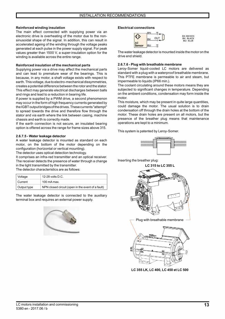
2.6.7.5 - Water leakage detectorA water leakage detector is mounted as standard on each motor, on the bottom of the motor depending on the configuration (horizontal or vertical mounting). The detector uses optical detection technology.It comprises an infra-red transmitter and an optical receiver. The receiver detects the presence of water through a change in the light transmitted by the transmitter.The detector characteristics are as follows:
Voltage 12-28 volts D.C.
Current 100 mA max.
Output type NPN closed circuit (open in the event of a fault)
The water leakage detector is connected to the auxiliary terminal box and requires an external power supply.
Electrical connections
The water leakage detector is mounted inside the motor on the drive end shield.
2.6.7.6 - Plug with breathable membraneLeroy-Somer liquid-cooled LC motors are delivered as standard with a plug with a waterproof breathable membrane. This PTFE membrane is permeable to air and steam, but impermeable to liquids (IP66 min.).The coolant circulating around these motors means they are subjected to significant changes in temperature. Depending on the ambient conditions, condensation may form inside the motor. This moisture, which may be present in quite large quantities, could damage the motor. The usual solution is to drain condensation off through the drain holes at the bottom of the motor. These drain holes are present on all motors, but the presence of the breather plug means that maintenance operations are kept to a minimum.
This system is patented by Leroy-Somer.
Inserting the breather plug:LC 315 to LC 355 L
LC 355 LK, LC 400, LC 450 et LC 500
Plug with breathable membrane

14 LC motors installation and commissioning5380 en - 2017.06 / b
INSTALLATION RECOMMENDATIONS
L
H
L
H
L
H
2.7 - Electrical connections2.7.1 - Motor terminal boxes2.7.1.1 - Main terminal boxTerminal boxes for LC 315, LC 315 LK and LC 355 (excluding LK versions) motors in a B3 housing are mounted on top of the motor. The standard position of the cable outputs is on the right as seen from the drive end, although they can be positioned on the left or the front as an option.
A: Standard position
BD
Terminal boxes for LC 355 LK to LC 500 motors are mounted at a 45° angle on the right as seen from the drive end. The cable outputs can be via the bottom as standard or via the top as an option. The terminal box positioned at a 45° angle on the left is also available as an option
Dimensions of cable gland mounting plates
Useful drilling area for cable gland mounting plates
(dimensions in mm)
Motor type DiagramWithout terminal
box spacer (standard)
With terminal box spacer
(optional*)
LC 315 LA/LB
1 H = 115W = 125
H = 135W = 280
LC 315 LKA/LKB/LKCLC 355 LA/LB/LCLC 355 LKA/LKB/LKC
2 H = 170W = 460
H = 170W = 460
LC 400 LA/LB
LC 400 LKA
LC 450 LA/LB
LC 500 M/L 3 - H = 290W = 774
* Standard for LC 500 motor
Diagram 1
Diagram 2
Diagram 3
MotorsLC 315 to LC 355
(excluding LC 355 LK)
MotorsLC 355 LK to LC 500
SIZE AND DIMENSIONS OF THE MAIN TERMINAL BOXES
LC 315 L - 315 LK - 355 L
Dimensions in millimetres
B: Standard positionD

15LC motors installation and commissioning5380 en - 2017.06 / b
INSTALLATION RECOMMENDATIONS
LC 355 LK - 400 L - 400 LK - 450 L Dimensions in millimetres
LC 500
This configuration allows up to 12 conductors to be connected per phase
2.7.1.2 - Auxiliary terminal boxesAn auxiliary terminal box for additional equipment (water leakage detector for example) is available as standard on these motors. It has 2 plugged drill holes (ISO 16).A second auxiliary terminal box with 2 plugged drill holes (ISO 20) can be mounted on request (for connecting thermal protection devices for example).

16 LC motors installation and commissioning5380 en - 2017.06 / b
INSTALLATION RECOMMENDATIONS
2.7.3 - Power supply cable cross-sections The higher the current, the greater the voltage drop in the cables (standard NFC 15.100 or end user's national standard). The voltage drop should therefore be calculated for the starting current to see if this is suitable for the application.
If the most important criterion is the starting torque (or starting time), the voltage drop should be limited to 3% maximum (the equivalent of a loss of torque of around 6 to 8%).The chart below can be used to select the conductors according to the length of the supply cables and the starting current, in order to limit the voltage drop to 3% maximum.
1 2 3 4 5 6 7 8 9 10 2 3 4 5 6 7 8 9 100 2 3 4 5 2 3 4 56 7 8 9 100010
20
30
40
5060708090
100
200
300
400
500600700800900
1000Length in m Maximum voltage drop 3% (three-phase circuits - copper cable)
Current in AStarting current
1 1.5 2.5 4 6 10 16 35 50 75 9025 Conductor cross-section
This table does not allow the installer to dispense with checking the protective systems.
For motors with flying leads, the power supply cable must not be used for handling.
2.7.2 - Tightening capacity of cable glands (optional)
Adapt the cable gland andits reducer, if present, to
the diameter of the cable being used. In order to maintain the motor's original IP55 protection, it is essential to tighten the cable gland seal correctly (so that it cannot be unscrewed by hand).When there are several cable glands and some are not being used, ensure that they are always covered and tighten them so that they also cannot be unscrewed by hand.
Cable gland typeMin. cable Ø - Max. cable Ø (mm)
Polyamide cable gland
Brass cable gland
ISO M16 5 - 10 5.5 - 9.5ISO M20 9.5 - 15 8.5 - 13ISO M25 13 - 19 12 - 17ISO M32 15 - 25 15 - 22ISO M40 21 - 32 19.5 - 28ISO M50 26 - 38 25.5 - 36ISO M63 31 - 34 33 - 46ISO M75 - 37 - 53ISO M90 - 40 - 62ISO M110 - 60 - 82
Ø m
in.
Ø m
ax.

17LC motors installation and commissioning5380 en - 2017.06 / b
INSTALLATION RECOMMENDATIONS
2.7.4 - Motor-drive connection2.7.4.1 - EnvironmentInfluence of the mains supplyEach industrial power supply has its own intrinsic characteristics (short-circuit capability, voltage value and fluctuation, phase imbalance, etc.) and supplies equipment some of which can distort its voltage either permanently or temporarily (notches, voltage dips, overvoltage, etc.). The quality of the mains supply has an impact on the performance and reliability of electronic equipment, especially variable speed drives. Nidec drives are designed to operate with the mains supplies typically found on industrial sites throughout the world. However, for each installation, it is important to know the characteristics of the mains supply so that you can take corrective steps in the event of abnormal conditions.
Transient overvoltagesThere are numerous sources of overvoltages on an electrical installation:• Connection/disconnection of banks of power factor correction capacitors• High-power thyristor-controlled equipment (oven, DC drive, etc.)• Overhead power supply
Connection/disconnection of a bank of power factor correction capacitorsConnecting power factor correction capacitors in parallel on the drive power supply line when the drive is running can generate transient overvoltages that are likely to trip the drive safety devices, or even damage it in extreme cases. If banks of power factor correction capacitors are used on the power supply line, make sure that:• The threshold between steps is low enough to avoid causing overvoltage on the line• The capacitors are not permanently connected
Presence of commutation notches on the lineWhen high-power thyristor-controlled equipment is connected on the same line as the drive, it is essential to ensure that the harmonics generated by the commutation notches do not excessively distort the mains voltage and do not create voltage peaks with amplitude higher than 1.6 x mains Vrms. If this is the case, it is essential to take corrective measures to guarantee the mains quality.
Unbalanced power supplyIn the same way as can be seen on an electric motor, the line phase voltage imbalance of a drive may have consequences on its operation. Please refer to the drive installation manual.
Equipotential bondingThe equipotential earth bonding of some industrial sites is not always observed. This lack of equipotentiality leads to leakage currents which flow via the earth cables (green/yellow), the machine chassis, the pipework, etc. and also via the electrical equipment. In some extreme cases, these currents can trip the drive. It is essential that the earth network is designed and implemented by the installation supervisor so that its impedance is as low as possible, so as to distribute the fault currents and high-frequency currents without them passing through electrical equipment. Metal grounds must be mechanically connected to each other with the largest possible
electrical contact area. Under no circumstances can earth connections designed to protect people, by linking metal grounds to earth via a cable, serve as a substitute for ground connections (see IEC 61000-5-2).The immunity and radio-frequency emission level are directly linked to the quality of the ground connections.
2.7.4.2 - Good wiring practiceIt is the responsibility of the user and/or the installer to connect the variable speed drive system in accordance with the current legislation and regulations in the country of use. This is particularly important as concerns cable size and connection of earths and grounds.
2.7.4.3 - Connecting the power cable shieldingTo ensure the safety of personnel, the size of the earthing cables should be determined individually in accordance with local regulations.For compliance with standard EN 61800-3, the power conductors between drive and motor must be shielded. Use a special variable speed cable: shielded with low stray capacity and with 3 PE conductors 120° apart (see diagram below). There is no need to shield the drive power supply cables.
U
V
Shielding
PEPE
PE
W
CAUTION: The configuration below is only acceptable if the motor cables incorporate phase conductors with a cross-section of less than 10 mm2 (motors < 30 kW/40 HP).
Shielding
The use of shielded single core cables is prohibited.
18 LC motors installation and commissioning5380 en - 2017.06 / b
INSTALLATION RECOMMENDATIONS
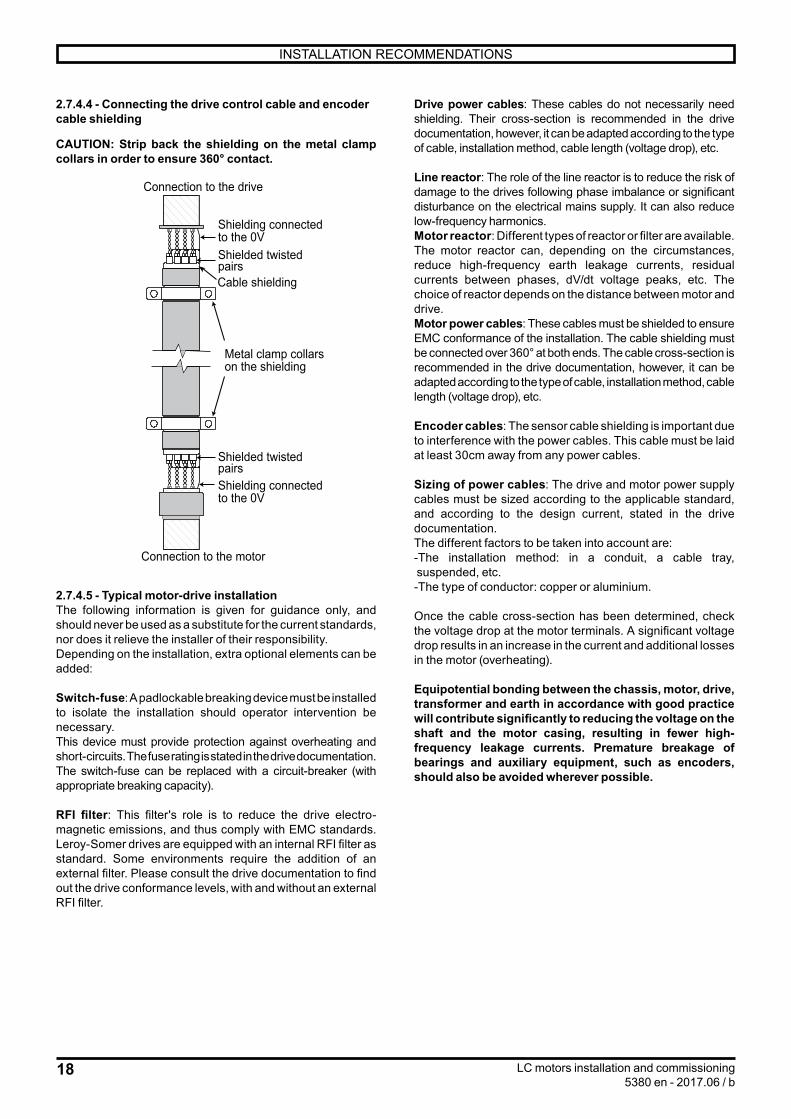
2.7.4.4 - Connecting the drive control cable and encoder cable shielding
CAUTION: Strip back the shielding on the metal clamp collars in order to ensure 360° contact.
Metal clamp collars on the shielding
Shielding connected to the 0V
Shielding connected to the 0V
Shielded twisted pairs
Shielded twisted pairs
Cable shielding
Connection to the drive
Connection to the motor
2.7.4.5 - Typical motor-drive installationThe following information is given for guidance only, and should never be used as a substitute for the current standards, nor does it relieve the installer of their responsibility.Depending on the installation, extra optional elements can be added:
Switch-fuse: A padlockable breaking device must be installed to isolate the installation should operator intervention be necessary.This device must provide protection against overheating and short-circuits. The fuse rating is stated in the drive documentation. The switch-fuse can be replaced with a circuit-breaker (with appropriate breaking capacity).
RFI filter: This filter's role is to reduce the drive electro-magnetic emissions, and thus comply with EMC standards. Leroy-Somer drives are equipped with an internal RFI filter as standard. Some environments require the addition of an external filter. Please consult the drive documentation to find out the drive conformance levels, with and without an external RFI filter.
Drive power cables: These cables do not necessarily need shielding. Their cross-section is recommended in the drive documentation, however, it can be adapted according to the type of cable, installation method, cable length (voltage drop), etc.
Line reactor: The role of the line reactor is to reduce the risk of damage to the drives following phase imbalance or significant disturbance on the electrical mains supply. It can also reduce low-frequency harmonics.Motor reactor: Different types of reactor or filter are available. The motor reactor can, depending on the circumstances, reduce high-frequency earth leakage currents, residual currents between phases, dV/dt voltage peaks, etc. The choice of reactor depends on the distance between motor and drive.Motor power cables: These cables must be shielded to ensure EMC conformance of the installation. The cable shielding must be connected over 360° at both ends. The cable cross-section is recommended in the drive documentation, however, it can be adapted according to the type of cable, installation method, cable length (voltage drop), etc.
Encoder cables: The sensor cable shielding is important due to interference with the power cables. This cable must be laid at least 30cm away from any power cables.
Sizing of power cables: The drive and motor power supply cables must be sized according to the applicable standard, and according to the design current, stated in the drive documentation.The different factors to be taken into account are:- The installation method: in a conduit, a cable tray, suspended, etc.- The type of conductor: copper or aluminium.
Once the cable cross-section has been determined, check the voltage drop at the motor terminals. A significant voltage drop results in an increase in the current and additional losses in the motor (overheating).
Equipotential bonding between the chassis, motor, drive, transformer and earth in accordance with good practice will contribute significantly to reducing the voltage on the shaft and the motor casing, resulting in fewer high-frequency leakage currents. Premature breakage of bearings and auxiliary equipment, such as encoders, should also be avoided wherever possible.

19LC motors installation and commissioning5380 en - 2017.06 / b
INSTALLATION RECOMMENDATIONS
L1 L2 L3 PE
U V W PE
PE
PE
DRIVE
Optional RFI filter
Mains supply
Switch-fuse
Optional line reactor
Optional encoder
Encoder cable
HF flat braid(see section 2.7.7)
Optional motor
reactor
2.7.5 - Terminal block wiring diagram
Particular attention must be paid to the information on the nameplate in order to choose
the correct type of connection for the supply voltage.
All motors are supplied with a wiring diagram in the terminal box (if required, ask the supplier for this diagram, specifying the motor type and number shown on the motor nameplate). The connector links required for coupling can be found inside the terminal box.The standard wiring diagrams are as follows:
For LC 315 L, 315 LK and 355 L motors, connection is on 6 terminals:
W2 U2 V2
L1 L2 L3
U1 V1 W1
Lowest voltage
W2 U2 V2
L1 L2 L3
U1 V1 W1
Highest voltage
For LC 355 LK, 400 L, 400 LK, 450 and 500 motors, connection is on 12 terminals:
W2 W2
U1
L1 L2 L3
U1
U2 U2
V1 V1
V2 V2
W1 W1
Lowest voltage
W2 W2
U1
L1 L2 L3
U1
U2 U2
V1 V1
V2 V2
W1 W1
Highest voltage
When the motor is powered by a drive, L1, L2 and L3 are replaced by the U, V and W connections on the drive.
20 LC motors installation and commissioning5380 en - 2017.06 / b
INSTALLATION RECOMMENDATIONS
2.7.6 - Direction of rotationIn all cases, the direction of rotation from the shaft end is given by:
L1L2L3
U1V1W1
If 2 phases of the power supply are changed over, the motor will run in an anti-clockwise direction (check first that the motor has been designed to run in both directions of rotation).
2.7.7 - Earth terminalThe earth terminal is located inside the terminal box. Consisting of a threaded stud with a hexagonal nut, it is used to connect cables with cross-sections at least as large as the cross-section of the phase conductors.It is identified by the symbol in the terminal box moulding.There is also an earth terminal on one of the feet of the housing; another terminal can be requested as an option.For Drive application, a grounding bar is systematically fitted inside the terminal box, with earths straps and terminal box spacer, as provided by the option described on page 57 § ''Motor Protection" of technical catalog n° 5370en.
It is compulsory to earth the motor. Earthing must be performed in accordance with current
regulations (regarding protection of workers).
When the motor is controlled by a drive, refer to section 2.7.4 for the earth connections.
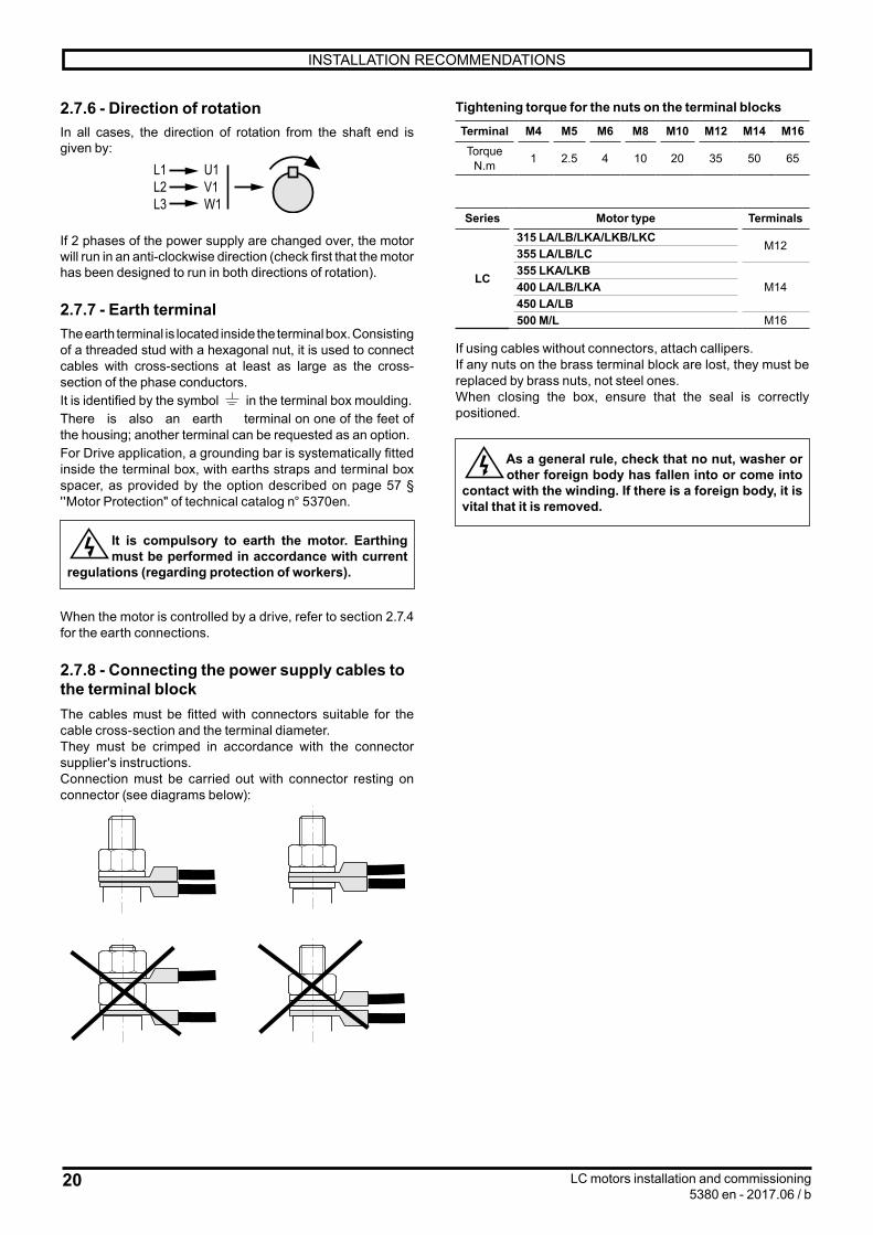
2.7.8 - Connecting the power supply cables to the terminal blockThe cables must be fitted with connectors suitable for the cable cross-section and the terminal diameter.They must be crimped in accordance with the connector supplier's instructions.Connection must be carried out with connector resting on connector (see diagrams below):
Tightening torque for the nuts on the terminal blocks
Terminal M4 M5 M6 M8 M10 M12 M14 M16Torque
N.m 1 2.5 4 10 20 35 50 65
Series Motor type Terminals
LC
315 LA/LB/LKA/LKB/LKCM12
355 LA/LB/LC355 LKA/LKB
M14400 LA/LB/LKA450 LA/LB500 M/L M16
If using cables without connectors, attach callipers.If any nuts on the brass terminal block are lost, they must be replaced by brass nuts, not steel ones.When closing the box, ensure that the seal is correctly positioned.
As a general rule, check that no nut, washer or other foreign body has fallen into or come into
contact with the winding. If there is a foreign body, it is vital that it is removed.

21LC motors installation and commissioning5380 en - 2017.06 / b
INSTALLATION RECOMMENDATIONS
Dimensions in millimetres2.8 - Connecting the cooling system
Hb
Lh
LfLf/2
TypeDimensions of the water connection flanges
Size Lf Lh HbLC 315 LA DN25-PN16 EN1092-1 140 0 340
LC 315 LB DN25-PN16 EN1092-1 140 0 340
LC 315 LKA DN32-PN16 EN1092-1 160 0 380
LC 315 LB DN32-PN16 EN1092-1 160 0 380
LC 315 LKC (2 & 4-pole) DN32-PN16 EN1092-1 160 0 380
LC 355 LA DN32-PN16 EN1092-1 160 0 380
LC 355 LB DN32-PN16 EN1092-1 160 0 380
LC 355 LC (4-pole) DN32-PN16 EN1092-1 160 0 380
LC 355 LKA DN50-PN16 EN1092-1 180 150 385
LC 355 LKB DN50-PN16 EN1092-1 180 150 385
LC 355 LKC (6-pole) DN50-PN16 EN1092-1 180 150 385
LC 400 LA DN50-PN16 EN1092-1 180 150 385
LC 400 LB (6-pole) DN50-PN16 EN1092-1 180 150 385
LC 400 LKA DN50-PN16 EN1092-1 180 150 435
LC 450 LA DN50-PN16 EN1092-1 180 150 435
LC 450 LB DN50-PN16 EN1092-1 180 150 435
LC 500 M/L DN50-PN16 EN1092-1 180 150 500
Water circuit capacity of LC motors by frame size:
TypeQty
(in litres)
LC 315 12.5
LC 315 LK / LC 355 L 16
LC 355 LK / LC 400 L 21
LC 400 LK / LC 450 27
LC 500 M 43
LC 500 L 51

22 LC motors installation and commissioning5380 en - 2017.06 / b
START-UP
2.9 - FillingPrecautions to be taken during filling:- Check that the plugs are securely in the drain holes.- Open the motor's air vents.- Make sure that the water inlet and outlet valves are clean.- Attach the cooling water circuit pipes to the motor's inlet and outlet valves.- Turn the water supply on.- Fill the motor.- When the water level reaches the air vent, turn the water off.- Close the motor's air vents.- Pressurise the circuit until it reaches the working pressure.Note: The water circuit inlet and outlet are marked on the motor.
Water circuit bleed valve and degassing valves:LC motors are fitted as standard with water circuit bleed valves and degassing valves.
LC 315 L to LC 355 L
Degassing3/8ʺ
LC 355 LK to LC 500
3 - START-UP3.1 - Initial start-upActivate the water cooling system, making sure you check the flow rate, pressure and temperature of the water.Before commissioning the motor, rotate it at no load (no mechanical load) for 2 to 5 minutes, to ensure there is no abnormal noise. If there is an abnormal noise, see section 6.
3.2 - Operation
The motor must never operate without water in the cooling system.
Check the water flow rate and pressure according to the characteristics indicated on the motor nameplate.
Draining 3/8"
DegassingLC 355 LK to LC 450 = 3/8ʺLC 500 = 1/2ʺ
Degassing1/2ʺ
DrainingLC 355 LK to LC 450 = 3/8ʺLC 500 = 1/2ʺ
Draining1/2ʺ
23LC motors installation and commissioning5380 en - 2017.06 / b
CHECKS AFTER START-UP
4 - CHECKS AFTER START-UP4.1 - Checking the cooling systemFor checking and operational purposes, it is recommended that the water temperature and the differential pressure are checked regularly and recorded at the water inlet and outlet. These measurements should be consistently compared to the initial values: the differential pressure and water temperature indicate the potential need to clean the water circuit.
4.2 - Mechanical checkAfter approximately 50 hours’ operation, check that the screws fixing the motor and the coupling device are still tight; check the tightness of any cable glands and the fixing screws on the terminal box. In the case of chain or belt transmission, check that the tension is correctly adjusted.
4.3 - CleaningTo ensure the motor operates correctly, remove any dust or foreign bodies.Necessary precaution: Check that the motor is totally sealed (terminal box, drain holes, etc.) before carrying out any cleaning operation.Dry cleaning (vacuuming or compressed air) is always preferable to wet cleaning.
Always clean at reduced pressure from the centre of the motor outwards to avoid introducing dust
and particles under the seals.
4.4 - Draining condensationTemperature variations cause condensation to form inside the motor, which must be removed before it adversely affects motor operation.
Condensation drain holes, located at the bottom of the motors (taking account of their operating position) are sealed with plugs which must be removed and then replaced every six months (if they were not replaced, the motor degree of protection would no longer be maintained). Clean the holes and plugs before reassembly.
Plug with breathable membraneMake sure that this device is not damaged or blocked.
Note: In conditions of high humidity and significant temperature variations, a shorter period is recommended.As long as it poses no risk to the motor protection, the condensation drain plugs can be removed.
4.5 - Greasing4.5.1 - Type of greaseThe type of grease is shown on the motor nameplate.Polyrex EM103 grease is used as standard and we recommend that this is used for subsequent lubrication. Avoid mixing greases (even if the base soaps are the same).
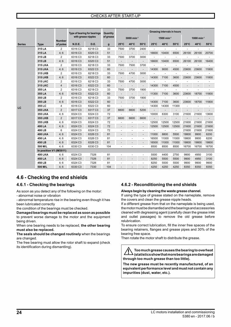
4.5.2 - Bearings with grease nipplesThe bearings are lubricated in the factory.The end shields are fitted with bearings lubricated by Técalémit Hydraulic M8 x 125 grease nipples.
The frequency of lubrication and quantity and quality of grease are indicated on the nameplates.
Refer to these to ensure correct lubrication of the bearings.
Even in the event of prolonged storage or downtime, the interval between 2 greasing
operations should never exceed 2 years.
For vertical shaft machines, the greasing intervals will be approximately 50% of the values stated in
the table overleaf.
24 LC motors installation and commissioning5380 en - 2017.06 / b
CHECKS AFTER START-UP
Series TypeNumber of poles
Type of bearing for bearings with grease nipples
Quantity of grease
Greasing intervals in hours
3000 min-1 1500 min-1 1000 min-1
N.D.E. D.E. g 25°C 40°C 55°C 25°C 40°C 55°C 25°C 40°C 55°C
LC
315 LA 2 6316 C3 6218 C3 33 7500 3700 2400 - - - - - -315 LA 4; 6 6316 C3 6320 C3 51 - - - 16600 10400 6500 26100 26100 20700315 LB 2 6316 C3 6218 C3 33 7500 3700 3000 - - - - - -315 LB 4; 6 6316 C3 6320 C3 51 - - - 16600 10400 6500 26100 26100 16400315 LKA 2 6316 C3 6218 C3 33 7500 7500 3700 - - - - - -315 LKA 4; 6 6316 C3 6322 C3 60 - - - 14300 9000 4500 23600 23600 11800315 LKB 2 6316 C3 6218 C3 33 7500 4700 3000 - - - - - -315 LKB 4; 6 6316 C3 6322 C3 60 - - - 14300 7100 3600 23600 23600 11800315 LKC 2 6316 C3 6218 C3 33 7500 4700 3000 - - - - - -315 LKC 4 6316 C3 6322 C3 60 - - - 14300 7100 4500 - - -355 LA 2 6316 C3 6218 C3 33 7500 3700 1900 - - - - - -355 LA 4; 6 6316 C3 6322 C3 60 - - - 11300 7100 3600 23600 18700 11800355 LB 2 6316 C3 6218 C3 33 7500 3700 1900 - - - - - -355 LB 4; 6 6316 C3 6322 C3 60 - - - 14300 7100 3600 23600 18700 11800355 LC 4 6316 C3 6322 C3 60 - - - 14300 14300 11300 - - -355 LKA 2 6317 C3 6317 C3 37 6600 6600 5200 - - - - - -355 LKA 4; 6 6324 C3 6324 C3 72 - - - 10000 6300 3100 21600 21600 13600355 LKB 2 6317 C3 6317 C3 37 6600 6600 6600 - - - - - -355 LKB 4; 6 6324 C3 6324 C3 72 - - - 12500 12500 12500 21600 21600 21600400 LA 4; 6 6324 C3 6324 C3 72 - - - 12500 12500 12500 21600 21600 21600400 LB 6 6324 C3 6324 C3 72 - - - - - - 21600 21600 21600400 LKA 4; 6 6324 C3 6326 C3 81 - - - 11000 8800 5500 19800 9900 6200450 LA 4; 6 6324 C3 6326 C3 81 - - - 16500 11000 11000 19800 9900 6200450 LB 4; 6 6324 C3 6326 C3 81 - - - 16500 11000 11000 19800 19800 19800500 M/L 4; 6 6330 C3 6330 C3 104 - - - 8500 8500 8500 16700 16700 16700In position V1 (IM3011)400 LKA 4; 6 6324 C3 7326 81 - - - 5500 4400 2750 9900 4950 3100450 LA 4; 6 6324 C3 7326 81 - - - 8250 5500 5500 9900 4950 3100450 LB 4; 6 6324 C3 7326 81 - - - 8250 5500 5500 9900 9900 9900500 M/L 4; 6 6330 C3 7330 104 - - - 4250 4250 4250 8350 8350 8350
4.6 - Checking the end shields4.6.1 - Checking the bearingsAs soon as you detect any of the following on the motor:- abnormal noise or vibration- abnormal temperature rise in the bearing even though it has been lubricated correctlythe condition of the bearings must be checked.Damaged bearings must be replaced as soon as possible to prevent worse damage to the motor and the equipment being driven.When one bearing needs to be replaced, the other bearing must also be replaced.The seals should be changed routinely when the bearings are changed.The free bearing must allow the rotor shaft to expand (check its identification during dismantling).
4.6.2 - Reconditioning the end shieldsAlways begin by cleaning the waste grease channel.If using the type of grease stated on the nameplate, remove the covers and clean the grease nipple heads.If a different grease from that on the nameplate is being used, the motor must be dismantled and the bearings and accessories cleaned with degreasing agent (carefully clean the grease inlet and outlet passages) to remove the old grease before relubrication.To ensure correct lubrication, fill the inner free spaces of the bearing retainers, flanges and grease pipes and 30% of the bearing free space.Then rotate the motor shaft to distribute the grease.
Too much grease causes the bearing to overheat (statistics show that more bearings are damaged
through too much grease than too little).The new grease must be recently manufactured, of an equivalent performance level and must not contain any impurities (dust, water, etc.).

25LC motors installation and commissioning5380 en - 2017.06 / b
PREVENTIVE MAINTENANCE
5 - PREVENTIVE MAINTENANCEPlease consult LEROY-SOMER who, in its continuous search for ways to help customers, has evaluated numerous methods of preventive maintenance.The diagram and the table below give the recommended equipment to use and the ideal positions to take measurements of all parameters which can affect the operation of the machine, such as eccentricity, vibration, state of the bearings, structural problems, electrical problems, etc.
Detector MeasurementMeasurement points
M 01V M 01H M 02V M 02H M 02A Shaft E01 E02 E03
� Accelerometer For measuring vibrations • • • • •� Photo-electric cell
For measuring speed and phase (balancing) •
� Clamp ammeterFor measuring current (D.C. and 3-phase A.C.) • • •
� Voltage probe For measuring voltage • • •� Infra-red probe For measuring temperature • •
The following actions are necessary for LC motors:
- Clean and check the cooling circuit regularly according to the instructions in this manual.
- The coating on the housing and the inlet and outlet valves must always be kept in good condition.
- If there is a risk of freezing, anti-freeze must be added to the cooling water.
- Always check that the correct proportions of additives are added to the water to protect the machine from corrosion and algae. The type and quantity of additive to use should be indicated by the additive manufacturer according to the machine installation conditions.
M 01V M 02V
M 02A
M 02HM 01H
1
3
42
5

26 LC motors installation and commissioning5380 en - 2017.06 / b
TROUBLESHOOTING GUIDE
6 - TROUBLESHOOTING GUIDE
Incident Possible cause Remedy
Abnormal noise Originating in motor or machine being driven? Uncouple the motor from the equipment being driven and test the motor on its own
Noisy motor Mechanical cause if the noise persists after switching off the power supply (if the motor is operating with a drive, set the drive to "freewheel" mode)
- Vibration - Check that the key conforms to the type of balancing (see section 2.5)
- Damaged bearings - Change the bearings
- Mechanical friction: coupling - Check and replace the faulty part
Electrical cause if the noise stops after switching off the power supply
- Check the power supply at the motor terminals- Check the drive settings (if used)
- Normal voltage and 3 phases balanced - Check the connection of the terminal block and the tightening of the connectors
- Abnormal voltage - Check the power supply line
- Phase imbalance - Check the winding resistance
Other possible causes:- Incorrect drive parameter settings- Drive malfunction
- Refer to the drive manual
Motor heats abnormally
- Faulty supply voltage - Check
- Terminal connection fault - Check
- Overload - Check the current consumption in relation to that indicated on the motor nameplate
- Partial short-circuit - Check the electrical continuity of the windings and/or the installation
- Phase imbalance - Check the winding resistance
- Water leak - Check the condition of the water inlet and outlet valves- Check the pipe connections- Check the water pressure level
Other possible causes:- Incorrect drive parameter settings- Drive malfunction
- Refer to the drive manual
Motor does not start No load- Mechanical obstruction
When switched off:- Check by hand that the shaft rotates freely
- Broken power supply line - Check the fuses, electrical protection, starting device
- Position feedback (drive message) - Check the wiring, drive settings and operation of the position sensor
- Thermal protection - Check
On load- Phase imbalance
When switched off:- Check the direction of rotation (phase order)- Check the resistance and continuity of the windings- Check the electrical protection
- Drive - Check the parameter settings and sizing (max. current that can be delivered by the drive)
- Position feedback (drive message) - Check the wiring, drive settings and operation of the position sensor
- Thermal protection - Check

27LC motors installation and commissioning5380 en - 2017.06 / b
POSITION OF LIFTING RINGS
7 - POSITION OF LIFTING RINGS
Position of lifting rings for lifting the motor only (not connected to the machine)
The regulations stipulate that over 25kg, suitable handling equipment must be used.All our motors are fitted with grab handles, making them easier to handle without risk.A diagram of the sling hoisting method appears below with the required dimensions.To prevent any damage to the motor during handling (for example, when changing the motor from a horizontal to a vertical position), it is vital to follow these instructions.
Motors intended for use in the vertical position may be delivered in the horizontal position on a
pallet. When the motor is pivoted, the shaft must under no circumstances be allowed to touch the ground, as the bearings may be irreparably damaged. Moreover, additional special precautions must be taken, as the integral motor lifting rings are not designed for pivoting the motor.
• Horizontal position
LC 315 and LC 355
LC 355 LK to LC 500
TypeDimensions in mm
La Lb Lc Ld
LC 315 950 490 475 670LC 355 1050 560 540 760LC 355 LK / LC 400 1220 - - 630LC 400 LK / LC 450 1410 - - 730LC 500 M 1720 - - 840LC 500 L 2020 - - 840
• Vertical position
La
La La
La
Ø 50 Ø 50
Lb
Ld (x3)
Lc
Ld
Ø 50 Ø 50
28 LC motors installation and commissioning5380 en - 2017.06 / b
SPARE PARTS
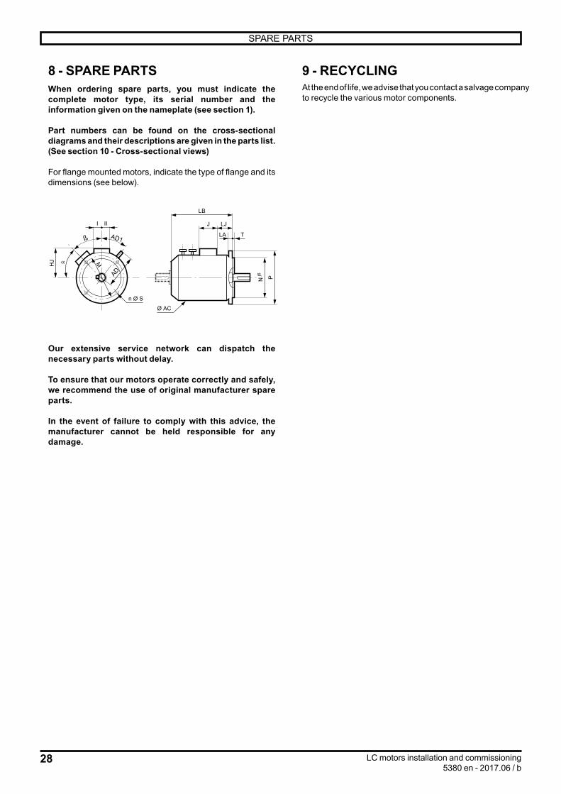
8 - SPARE PARTSWhen ordering spare parts, you must indicate the complete motor type, its serial number and the information given on the nameplate (see section 1).
Part numbers can be found on the cross-sectional diagrams and their descriptions are given in the parts list.(See section 10 - Cross-sectional views)
For flange mounted motors, indicate the type of flange and its dimensions (see below).
HJ
I II
n Ø S
LA
J LJ
LB
T
N Pj6
Ø AC
α M
AD
AD1ß
Our extensive service network can dispatch the necessary parts without delay.
To ensure that our motors operate correctly and safely, we recommend the use of original manufacturer spare parts.
In the event of failure to comply with this advice, the manufacturer cannot be held responsible for any damage.
9 - RECYCLINGAt the end of life, we advise that you contact a salvage company to recycle the various motor components.

29LC motors installation and commissioning5380 en - 2017.06 / b
CROSS-SECTIONAL VIEWS
10 - CROSS-SECTIONAL VIEWS
LC 315 - 355 L
25
13 17 12 11 20 15 13
6
21
22
19
8
18
164 314 18 24 10 5
14
23
7
2
91
Ref. Description Qty Ref. Description Qty1 Plug with breathable membrane 1 14 Plate seal 22 Shaft 1 15 Closure plate seal 13 Plug 3 16 NDE shield 14 Foot mounted housing 1 17 DE shield 15 Bearing retainer 1 18 Closure plate 26 Bearing retainer 1 19 Closure plate 17 Circlip 1 20 Closure plate 18 Circlip 1 21 Spring 69 Key 1 22 Bearing 1
10 Level controller 1 23 Bearing 111 Auxiliary terminal box assembly 1 24 Water leakage detector mount 112 Terminal box assembly 1 25 Breather mount 113 Grease nipple 2
LC 355 LK - 400 - 450 - 500
546203 28 121815
26
27
10
14
17 13 21
316
7
9
18
19
14
25
15
29
24
23
1
4
22
11
2
8
Ref. Description Qty Ref. Description Qty1 Plug with breathable membrane 1 16 NDE shield 12 Shaft 1 17 DE shield 13 Plug 4 18 Closure plate 24 Plug 5 19 Closure plate 15 Internal stirrer 1 20 Earth terminal 16 Foot mounted housing 1 21 Clamping plate 27 Bearing retainer 1 22 Link bridge 28 Bearing retainer 1 23 Swivel male connector 89 Circlip 1 24 Spring 8
10 Circlip 1 25 Bearing 111 Key 1 26 Bearing 112 Level controller 1 27 AEGIS 130 ring support 113 Balancing disc 1 28 Detector mount 114 Grease nipple 2 29 Tube 415 Plate seal 2


Moteurs Leroy-Somer SASSiège social : Boulevard Marcellin Leroy - CS 10015
16915 ANGOULÊME Cedex 9Société par Actions Simplifiées au capital de 65 800 512 $
RCS Angoulême 338 567 258www.leroy-somer.com