Embed Size (px)
Citation preview
3-phase induction motorsIE3 Premium efficiency
Variable and fixed speedFrame size 315 to 500
150 to 1500 kW
IMfinity®
Liquid cooled motors - LC series
The LC induction motors in this catalog are designed to achieve very high efficiency levels and operate at variable speed.
This catalog contains technical information about motors in the IE3 efficiency class (Premium efficiency) which can be used on an A.C. supply and also on a drive.
On request, Leroy-Somer is able to offer IE4 motor solutions.
All the motors in this catalog can be used at variable speed depending on the specified conditions.
All 2, 4 and 6-pole motors, rated 0.75 to 375 kW, offered for sale on the European Union market must be efficiency class IE3 or IE2 and used with a variable speed drive:- from 01/01/2015 for 7.5 to 375 kW ratings- from 01/01/2017 for 0.75 to 375 kW ratings
In addition, to be eligible for efficiency class IE3, the water inlet temperature for water-cooled motors must be between 0°C and 32°C.
3Leroy-Somer - Liquid-Cooled Motors - LC Series - 5370 en - 2017.05 / b
IMfinity® - LC Liquid-Cooled 3-Phase Induction Motors
Contents
GENERALIntroduction ...........................................................................4
Quality Commitment .............................................................5
Directive and Standards Relating to Motor Efficiency............6
Standards and Approvals ......................................................7
Regulations in the Main Countries ......................................10
ENVIRONMENTDefinition of “Index of Protection” ........................................11
Environmental Limitations...................................................12
Impregnation and Enhanced Protection ..............................13
Heating ...............................................................................14
External Finish ....................................................................15
Interference Suppression and Protection of People ............16
CONSTRUCTIONBearings and Bearing Life ...................................................17
Lubrication and Maintenance of Bearings ...........................18
OPERATIONDuty Cycle - Definitions .......................................................19
Supply Voltage ....................................................................22
Insulation Class - Temperature Rise and
Thermal Reserve ................................................................24
Starting Times and Starting Current ....................................25
Power - Torque - Efficiency - Power Factor (Cos ɸ) .............26
Noise Level .........................................................................29
Weighted Sound Level [dB(A) .............................................30
Vibrations ............................................................................31
Performance .......................................................................33
Starting Methods for Induction Motors ................................34
Braking ...............................................................................38
Use with a Variable Speed Drive .........................................40
Operation as an Asynchronous Generator ..........................47
Special Environments .........................................................49
TECHNICAL CHARACTERISTICS
Designation.........................................................................50
Identification .......................................................................51
Description of an LC Motor basic conception ......................53
Cooling ...............................................................................54
Standard Equipment ...........................................................56
Optional Features ...............................................................57
Handling .............................................................................58
ELECTRICAL CHARACTERISTICS
IE3 Mains Supply ................................................................59
IE3 Variable Speed Drive Supply ........................................61
Terminal Block Connection .................................................63
MECHANICAL CHARACTERISTICS
Mounting Arrangements......................................................64
Terminal Box Connection ....................................................65
Dimensions of Shaft Extensions .........................................69
Dimensions of Foot Mounted IM 1001 (IM B3) ....................70
Dimensions of Foot and Flange Mounted IM 2001
(IM B35) ............................................................................. 71
Dimensions of Flange Mounted IM 3001 (IM B5)
IM 3011 (IMV1) ...................................................................72
Dimensions - Water Connecting Flange ..............................73
Bearings and Lubrication ....................................................74
Axial Loads .........................................................................75
Radial Loads .......................................................................77
APPENDIX .........................................................................83
Configurator ........................................................................91
4 Leroy-Somer - Liquid-Cooled Motors - LC Series - 5370 en - 2017.05 / b
IMfinity® - LC Liquid-Cooled 3-Phase Induction Motors
GeneralIntroduction
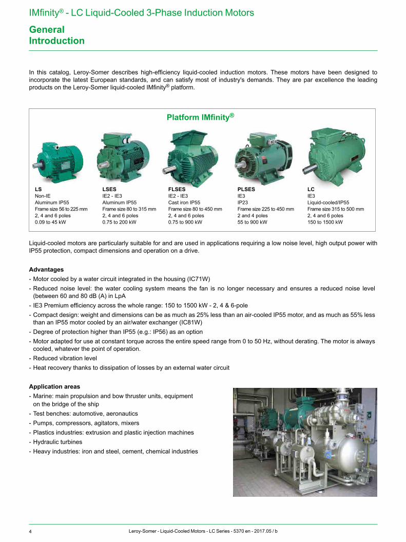
In this catalog, Leroy-Somer describes high-efficiency liquid-cooled induction motors. These motors have been designed to incorporate the latest European standards, and can satisfy most of industry's demands. They are par excellence the leading products on the Leroy-Somer liquid-cooled IMfinity® platform.
Platform IMfinity®
LSESIE2 - IE3Aluminum IP55Frame size 80 to 315 mm2, 4 and 6 poles0.75 to 200 kW
LSNon-IEAluminum IP55Frame size 56 to 225 mm2, 4 and 6 poles0.09 to 45 kW
FLSESIE2 - IE3Cast iron IP55Frame size 80 to 450 mm2, 4 and 6 poles0.75 to 900 kW
PLSESIE3IP23Frame size 225 to 450 mm2 and 4 poles55 to 900 kW
LCIE3Liquid-cooled/IP55Frame size 315 to 500 mm2, 4 and 6 poles150 to 1500 kW
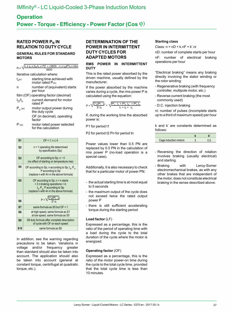
Liquid-cooled motors are particularly suitable for and are used in applications requiring a low noise level, high output power with IP55 protection, compact dimensions and operation on a drive.
Advantages- Motor cooled by a water circuit integrated in the housing (IC71W)- Reduced noise level: the water cooling system means the fan is no longer necessary and ensures a reduced noise level
(between 60 and 80 dB (A) in LpA- IE3 Premium efficiency across the whole range: 150 to 1500 kW - 2, 4 & 6-pole- Compact design: weight and dimensions can be as much as 25% less than an air-cooled IP55 motor, and as much as 55% less
than an IP55 motor cooled by an air/water exchanger (IC81W)- Degree of protection higher than IP55 (e.g.: IP56) as an option- Motor adapted for use at constant torque across the entire speed range from 0 to 50 Hz, without derating. The motor is always
cooled, whatever the point of operation.- Reduced vibration level- Heat recovery thanks to dissipation of losses by an external water circuit
Application areas- Marine: main propulsion and bow thruster units, equipment on the bridge of the ship- Test benches: automotive, aeronautics- Pumps, compressors, agitators, mixers- Plastics industries: extrusion and plastic injection machines- Hydraulic turbines- Heavy industries: iron and steel, cement, chemical industries
5Leroy-Somer - Liquid-Cooled Motors - LC Series - 5370 en - 2017.05 / b
IMfinity® - LC Liquid-Cooled 3-Phase Induction Motors
GeneralQuality Assurance
Leroy-Somer's quality management system is based on:- Tight control of procedures right from
the initial sales offering through to delivery to the customer, including the design process, manufacturing start-up and production.
- A total quality policy based on making continuous progress in improving operational procedures, involving all departments in the company in order to give customer satisfaction as regards delivery times, conformity and cost.
- Indicators used to monitor process performance.
- Corrective actions and advancements with tools such as FMECA, QFD, MAVP, MSP/MSQ and Hoshin type improvement workshops on flows, process re-engineering, plus Lean Manufacturing and Lean Office.
- Annual surveys, opinion polls and regular visits to customers in order to ascertain and detect their expectations.
Personnel are trained and take part in the analyses and the actions for continuously improving the procedures.
A special study of the motors in this catalog has been conducted to measure the impact of their life cycle on the environment. This eco-design process has resulted in the creation of a “Product Environmental Profile” (references 4592/4950/4951). Leroy-Somer has entrusted the certification of its expertise to various international organizations.Certification is granted by independent professional auditors, and recognizes the high standards of the company's quality assurance procedures. All activities resulting in the final version of the machine have therefore received official ISO 9001:2008 certification from the DNV.Similarly, our environmental approach has enabled us to obtain ISO 14001: 2004 certification.
Products for particular applications or those designed to operate in specific environments are also approved or certified by the following organizations: LCIE, DNV, INERIS, EFECTIS, UL, BSRIA, TUV, GOST, which check their technical performance against the various standards or recommendations.
ISO 9001 : 2008
6 Leroy-Somer - Liquid-Cooled Motors - LC Series - 5370 en - 2017.05 / b
IMfinity® - LC Liquid-Cooled 3-Phase Induction Motors
General
There have been a number of changes to the standards and new standards created in recent years. They mainly concern motor efficiency and their scope includes measurement methods and motor classification.Regulations are gradually being implemented, both nationally and internationally, in many countries in order to promote the use of high-efficiency motors (Europe, USA, Canada, Brazil, Australia, New Zealand, Korea, China, Israel, etc.).The new generation of Premium efficiency three-phase induction motors responds to changes in the standards as well as the latest demands of system integrators and users.
STANDARD IEC 60034-30-1(January 2014) defines the principle to be adopted and brings global harmonization to energy efficiency classes for electric motors throughout the world.
Motors concernedInduction or permanent magnet, single-phase and three-phase single-speed cage motors, on a sinusoidal A.C. supply.Scope:- Un from 50 to 1000 V- Pn from 0.12 to 1000 kW- 4, 6 and 8 poles- Continuous duty at rated power
without exceeding the specified insulation class. Generally known as S1 duty.
- 50 and 60 Hz frequency- On the A.C. supply- Rated for an ambient temperature
between -20°C and +60°C- Rated for altitude up to 4000 m- Water inlet temperature from 0°C to
+32°C
Motors not concerned- Motors with frequency inverter when
the motor cannot be tested without it.- Brake motors when they form an
integral part of the motor construction and can neither be removed nor supplied separately in order to be tested.
- Motors which are fully integrated in a machine and cannot be tested separately (such as rotor/stator).
STANDARD FOR MEASURING THE EFFICIENCY OF ELECTRIC MOTORS: IEC 60034-2-1 (September 2007)Standard IEC 60034-2-1 concerns asynchronous induction motors:- Single-phase and three-phase with
power ratings of 1 kW or less. The preferred method is the D.O.L. method
- Three-phase motors with power ratings above 1 kW. The preferred method is the summation of losses method with the total of additional losses measured.
Comments:- The standard for efficiency
measurement is very similar to the IEEE 112-B method used in North America.
- Since the measurement method is different, this means that for the same motor, the rated value will be different (usually lower) with IEC 60034-2-1 than with IEC 60034-2.
DIRECTIVE 2009/125/EC (21 October 2009) from the European Parliament established a framework for setting the eco-design requirements to be applied to “energy-using products”. These products are grouped in lots. Motors come under lot 11 of the eco-design program, as do pumps, fans and circulating pumps.
DECREE IMPLEMENTING EUROPEAN DIRECTIVE ErP (Energy Related Product) EC/640/2009 - LOT 11 (July 2009) + EU/4/2014 (January 2014)This is based on standard IEC 60034-30-1 and will define the efficiency classes whose use will be mandatory in the future. It specifies the efficiency levels to be attained for machines sold in the European market and outlines the timetable for their implementation.
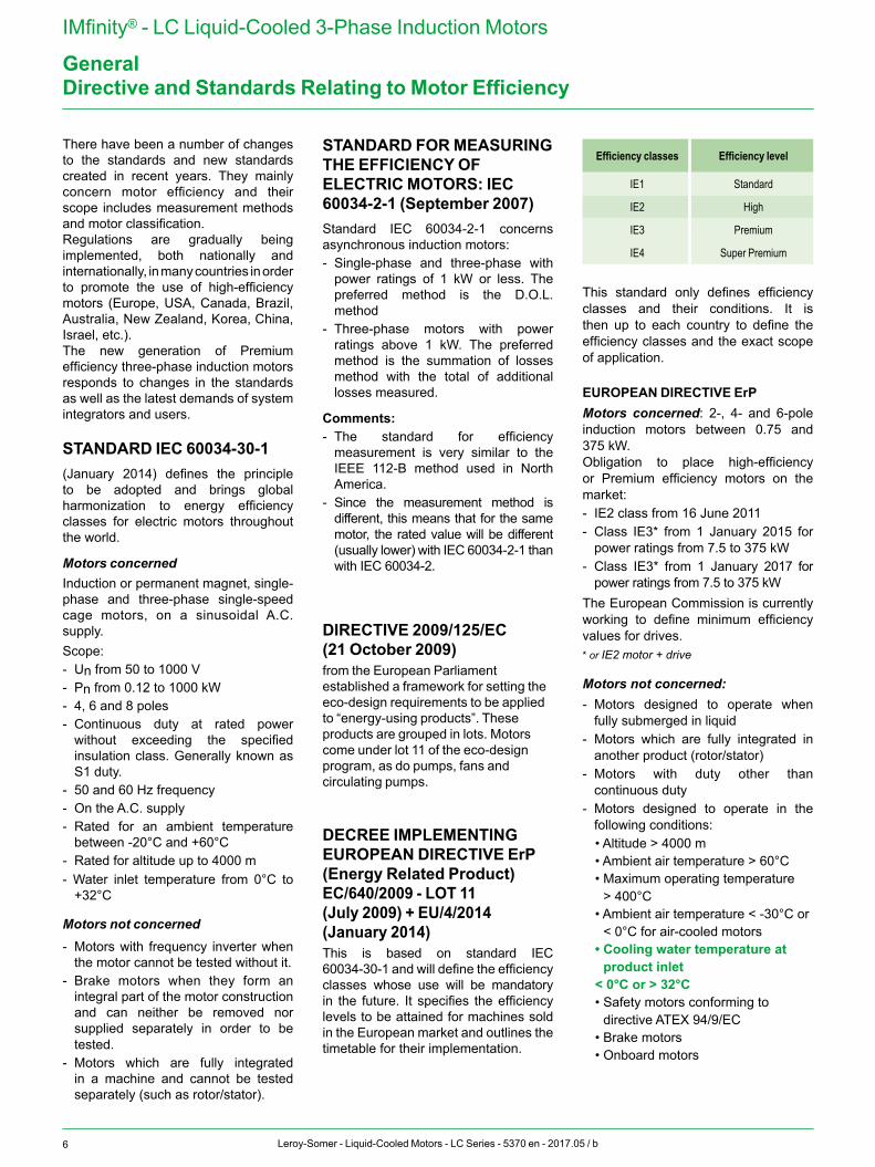
Efficiency classes Efficiency level
IE1 Standard
IE2 High
IE3 Premium
IE4 Super Premium
This standard only defines efficiency classes and their conditions. It is then up to each country to define the efficiency classes and the exact scope of application.
EUROPEAN DIRECTIVE ErPMotors concerned: 2-, 4- and 6-pole induction motors between 0.75 and 375 kW.Obligation to place high-efficiency or Premium efficiency motors on the market:- IE2 class from 16 June 2011- Class IE3* from 1 January 2015 for
power ratings from 7.5 to 375 kW- Class IE3* from 1 January 2017 for
power ratings from 7.5 to 375 kW The European Commission is currently working to define minimum efficiency values for drives.* or IE2 motor + drive
Motors not concerned:- Motors designed to operate when
fully submerged in liquid- Motors which are fully integrated in
another product (rotor/stator)- Motors with duty other than
continuous duty- Motors designed to operate in the
following conditions:• Altitude > 4000 m• Ambient air temperature > 60°C• Maximum operating temperature
> 400°C• Ambient air temperature < -30°C or
< 0°C for air-cooled motors• Cooling water temperature at
product inlet < 0°C or > 32°C• Safety motors conforming to
directive ATEX 94/9/EC• Brake motors• Onboard motors
Directive and Standards Relating to Motor Efficiency
7Leroy-Somer - Liquid-Cooled Motors - LC Series - 5370 en - 2017.05 / b
IMfinity® - LC Liquid-Cooled 3-Phase Induction Motors
GeneralStandards and Approvals
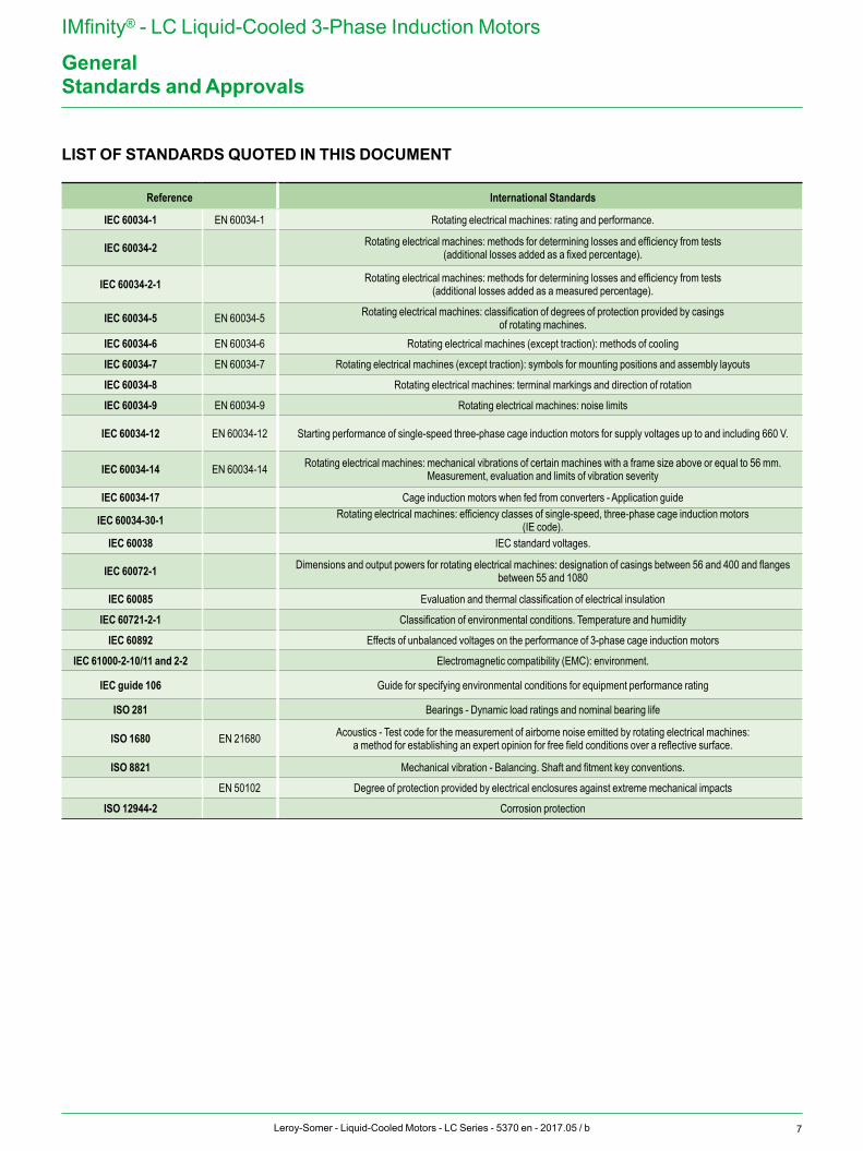
LIST OF STANDARDS QUOTED IN THIS DOCUMENT
Reference International Standards
IEC 60034-1 EN 60034-1 Rotating electrical machines: rating and performance.
IEC 60034-2 Rotating electrical machines: methods for determining losses and efficiency from tests (additional losses added as a fixed percentage).
IEC 60034-2-1 Rotating electrical machines: methods for determining losses and efficiency from tests (additional losses added as a measured percentage).
IEC 60034-5 EN 60034-5 Rotating electrical machines: classification of degrees of protection provided by casingsof rotating machines.
IEC 60034-6 EN 60034-6 Rotating electrical machines (except traction): methods of cooling
IEC 60034-7 EN 60034-7 Rotating electrical machines (except traction): symbols for mounting positions and assembly layouts
IEC 60034-8 Rotating electrical machines: terminal markings and direction of rotation
IEC 60034-9 EN 60034-9 Rotating electrical machines: noise limits
IEC 60034-12 EN 60034-12 Starting performance of single-speed three-phase cage induction motors for supply voltages up to and including 660 V.
IEC 60034-14 EN 60034-14 Rotating electrical machines: mechanical vibrations of certain machines with a frame size above or equal to 56 mm. Measurement, evaluation and limits of vibration severity
IEC 60034-17 Cage induction motors when fed from converters - Application guide
IEC 60034-30-1 Rotating electrical machines: efficiency classes of single-speed, three-phase cage induction motors(IE code).
IEC 60038 IEC standard voltages.
IEC 60072-1 Dimensions and output powers for rotating electrical machines: designation of casings between 56 and 400 and flanges between 55 and 1080
IEC 60085 Evaluation and thermal classification of electrical insulation
IEC 60721-2-1 Classification of environmental conditions. Temperature and humidity
IEC 60892 Effects of unbalanced voltages on the performance of 3-phase cage induction motors
IEC 61000-2-10/11 and 2-2 Electromagnetic compatibility (EMC): environment.
IEC guide 106 Guide for specifying environmental conditions for equipment performance rating
ISO 281 Bearings - Dynamic load ratings and nominal bearing life
ISO 1680 EN 21680 Acoustics - Test code for the measurement of airborne noise emitted by rotating electrical machines:a method for establishing an expert opinion for free field conditions over a reflective surface.
ISO 8821 Mechanical vibration - Balancing. Shaft and fitment key conventions.
EN 50102 Degree of protection provided by electrical enclosures against extreme mechanical impacts
ISO 12944-2 Corrosion protection
8 Leroy-Somer - Liquid-Cooled Motors - LC Series - 5370 en - 2017.05 / b
IMfinity® - LC Liquid-Cooled 3-Phase Induction Motors
GeneralStandards and Approvals
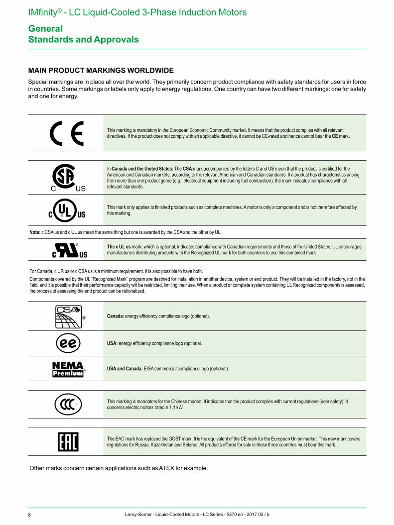
MAIN PRODUCT MARKINGS WORLDWIDE Special markings are in place all over the world. They primarily concern product compliance with safety standards for users in force in countries. Some markings or labels only apply to energy regulations. One country can have two different markings: one for safety and one for energy.
C US
C US
C US
ee
This marking is mandatory in the European Economic Community market. It means that the product complies with all relevant directives. If the product does not comply with an applicable directive, it cannot be CE-rated and hence cannot bear the CE mark.
C US
C US
C US
ee
In Canada and the United States: The CSA mark accompanied by the letters C and US mean that the product is certified for the American and Canadian markets, according to the relevant American and Canadian standards. If a product has characteristics arising from more than one product genre (e.g.: electrical equipment including fuel combustion), the mark indicates compliance with all relevant standards.
C US
C US
C US
ee
This mark only applies to finished products such as complete machines. A motor is only a component and is not therefore affected by this marking.
Note: c CSA us and c UL us mean the same thing but one is awarded by the CSA and the other by UL.
C US
C US
C US
ee
The c UL us mark, which is optional, indicates compliance with Canadian requirements and those of the United States. UL encourages manufacturers distributing products with the Recognized UL mark for both countries to use this combined mark.
For Canada, c UR us or c CSA us is a minimum requirement. It is also possible to have both.Components covered by the UL “Recognized Mark” program are destined for installation in another device, system or end product. They will be installed in the factory, not in the field, and it is possible that their performance capacity will be restricted, limiting their use. When a product or complete system containing UL Recognized components is assessed, the process of assessing the end product can be rationalized.
Canada: energy efficiency compliance logo (optional).C US
C US
C US
ee USA: energy efficiency compliance logo (optional.
USA and Canada: EISA commercial compliance logo (optional).
C US
C US
C US
ee
This marking is mandatory for the Chinese market. It indicates that the product complies with current regulations (user safety). It concerns electric motors rated ≤ 1.1 kW.
The EAC mark has replaced the GOST mark. It is the equivalent of the CE mark for the European Union market. This new mark covers regulations for Russia, Kazakhstan and Belarus. All products offered for sale in these three countries must bear this mark.
Other marks concern certain applications such as ATEX for example.
9Leroy-Somer - Liquid-Cooled Motors - LC Series - 5370 en - 2017.05 / b
IMfinity® - LC Liquid-Cooled 3-Phase Induction Motors
General
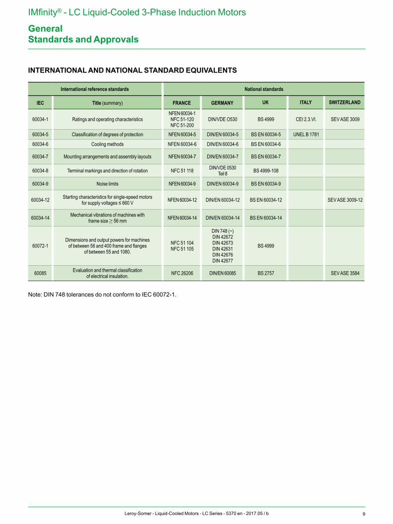
INTERNATIONAL AND NATIONAL STANDARD EQUIVALENTS
International reference standards National standards
IEC Title (summary) FRANCE GERMANY UK ITALY SWITZERLAND
60034-1 Ratings and operating characteristics NFEN 60034-1NFC 51-120NFC 51-200
DIN/VDE O530 BS 4999 CEI 2.3.VI. SEV ASE 3009
60034-5 Classification of degrees of protection NFEN 60034-5 DIN/EN 60034-5 BS EN 60034-5 UNEL B 1781
60034-6 Cooling methods NFEN 60034-6 DIN/EN 60034-6 BS EN 60034-6
60034-7 Mounting arrangements and assembly layouts NFEN 60034-7 DIN/EN 60034-7 BS EN 60034-7
60034-8 Terminal markings and direction of rotation NFC 51 118 DIN/VDE 0530Teil 8 BS 4999-108
60034-9 Noise limits NFEN 60034-9 DIN/EN 60034-9 BS EN 60034-9
60034-12 Starting characteristics for single-speed motors for supply voltages ≤ 660 V NFEN 60034-12 DIN/EN 60034-12 BS EN 60034-12 SEV ASE 3009-12
60034-14 Mechanical vibrations of machines with frame size ≥ 56 mm NFEN 60034-14 DIN/EN 60034-14 BS EN 60034-14
60072-1Dimensions and output powers for machines
of between 56 and 400 frame and flanges of between 55 and 1080.
NFC 51 104NFC 51 105
DIN 748 (~)DIN 42672DIN 42673DIN 42631DIN 42676DIN 42677
BS 4999
60085 Evaluation and thermal classification of electrical insulation. NFC 26206 DIN/EN 60085 BS 2757 SEV ASE 3584
Note: DIN 748 tolerances do not conform to IEC 60072-1.
Standards and Approvals
10 Leroy-Somer - Liquid-Cooled Motors - LC Series - 5370 en - 2017.05 / b
IMfinity® - LC Liquid-Cooled 3-Phase Induction Motors
GeneralRegulations in the Main Countries
Many countries have already implemented energy regulations concerning electric motors. Others are in the process of preparing them.
Some regulations require that before they can be offered for sale, products must be registered with the local authorities. In these cases, market surveillance is undertaken before the products are put into use, unlike the EU where the member states are responsible for organizing surveillance on their own territory.
The majority of countries requiring registration before products are offered for sale also usually require special product labeling.
For Europe, there is no special label. Only CE marking indicates that the product complies with all the relevant directives.
As regulations are constantly changing and vary from country to country, it is advisable to check for updates on a regular basis.
For more details of the efficiency classes applicable for each power rating and number of motor poles according to the timetable, please contact your local Leroy-Somer sales office.
11Leroy-Somer - Liquid-Cooled Motors - LC Series - 5370 en - 2017.05 / b
IMfinity® - LC Liquid-Cooled 3-Phase Induction Motors
Environment
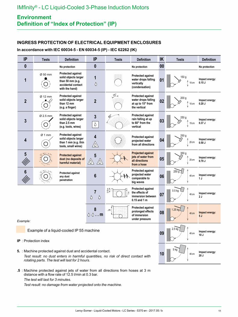
INGRESS PROTECTION OF ELECTRICAL EQUIPMENT ENCLOSURESIn accordance with IEC 60034-5 - EN 60034-5 (IP) - IEC 62262 (IK)
IP0
1
2
3
4
5
Tests Definition IP Tests Definition IK Tests Definition
1st number:Protection against solid objects
3rd number:Mechanical protection
Ø 50 mm
Ø 12 mm
No protection
Ø 2.5 mm
Ø 1 mm
2nd number:Protection against liquids
0 No protection 00 No protection
1
15°
2
3
4
60°
5
6
7
8 ..m
0.15 m
1 m
01 Impact energy:0.15 J
02 Impact energy:0.20 J
03 Impact energy:0.37 J
05 Impact energy:0.70 J
07 Impact energy:2 J
09 Impact energy:10 J
150 g
10 cm
250 g
15 cm
250 g
20 cm
250 g40 cm
0.5 kg40 cm
2.5 kg40 cm
. . m
6
200 g
10 cm
350 g
20 cm
04
06
081.25 kg
40 cm
10 Impact energy:20 J
5 kg40 cm
Impact energy:5 J
Impact energy:1 J
Impact energy:0.50 J
Protected against solid objects larger than 50 mm (e.g. accidental contact with the hand)
Protected against solid objects larger than 12 mm(e.g. a finger)
Protected against solid objects larger than 2.5 mm(e.g. tools, wires)
Protected against solid objects larger than 1 mm (e.g. thin tools, small wires)
Protected against dust (no deposits of harmful material)
Protected against any dust penetration
Protected against water drops falling vertically(condensation)
Protected against water drops falling at up to 15° from the vertical
Protected against rain falling at up to 60° from the vertical
Protected against projected water from all directions
Projected against jets of water from all directions from a hose
Protected against projected water comparable to big waves
Protected against the effects of immersion between 0.15 and 1 m
Protected against prolonged effects of immersion under pressureExample:
Example of a liquid-cooled IP 55 machine
IP : Protection index
5. : Machine protected against dust and accidental contact. Test result: no dust enters in harmful quantities, no risk of direct contact with
rotating parts. The test will last for 2 hours. .5 : Machine protected against jets of water from all directions from hoses at 3 m
distance with a flow rate of 12.5 l/min at 0.3 bar. The test will last for 3 minutes. Test result: no damage from water projected onto the machine.
Definition of “Index of Protection” (IP)
12 Leroy-Somer - Liquid-Cooled Motors - LC Series - 5370 en - 2017.05 / b
IMfinity® - LC Liquid-Cooled 3-Phase Induction Motors
Environment
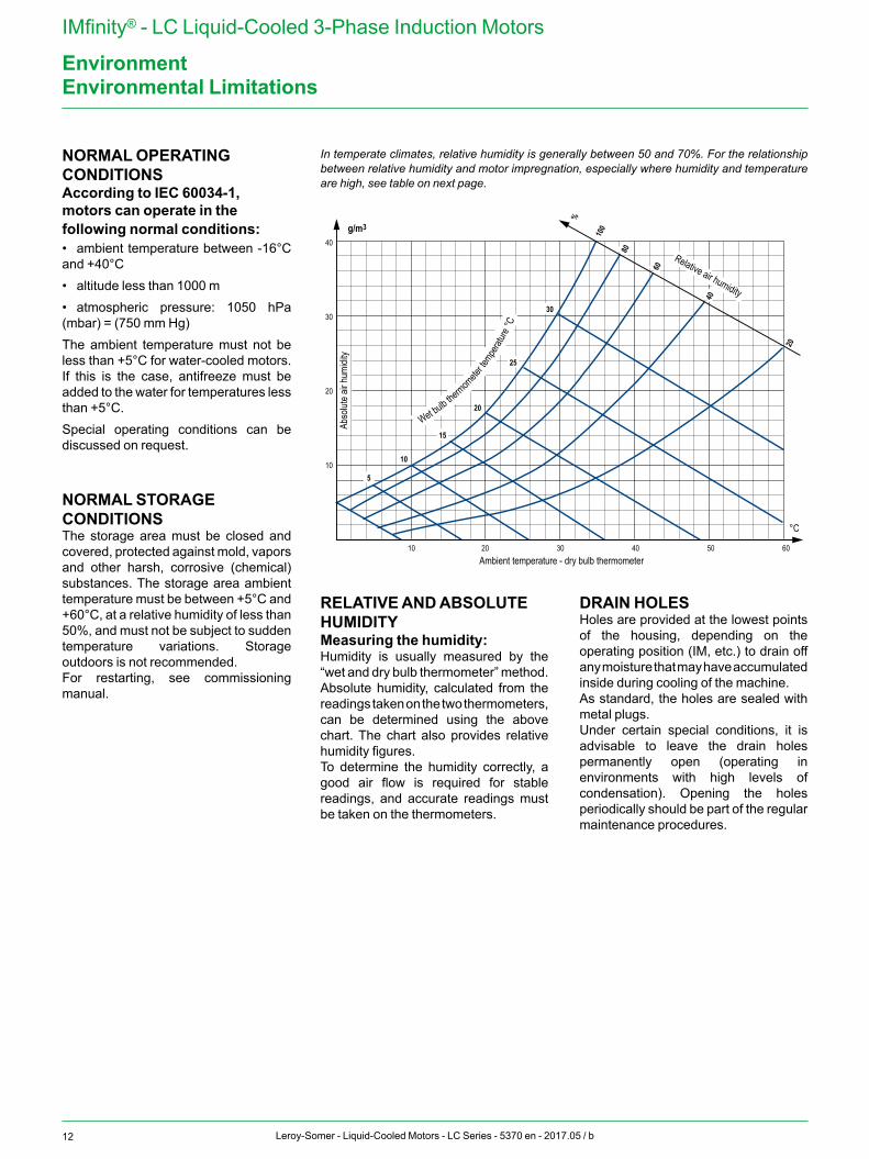
NORMAL OPERATING CONDITIONSAccording to IEC 60034-1, motors can operate in the following normal conditions:• ambient temperature between -16°C and +40°C• altitude less than 1000 m• atmospheric pressure: 1050 hPa (mbar) = (750 mm Hg)The ambient temperature must not be less than +5°C for water-cooled motors. If this is the case, antifreeze must be added to the water for temperatures less than +5°C.Special operating conditions can be discussed on request.
NORMAL STORAGE CONDITIONSThe storage area must be closed and covered, protected against mold, vapors and other harsh, corrosive (chemical) substances. The storage area ambient temperature must be between +5°C and +60°C, at a relative humidity of less than 50%, and must not be subject to sudden temperature variations. Storage outdoors is not recommended.For restarting, see commissioning manual.
RELATIVE AND ABSOLUTE HUMIDITYMeasuring the humidity:Humidity is usually measured by the “wet and dry bulb thermometer” method.Absolute humidity, calculated from the readings taken on the two thermometers, can be determined using the above chart. The chart also provides relative humidity figures.To determine the humidity correctly, a good air flow is required for stable readings, and accurate readings must be taken on the thermometers.
DRAIN HOLESHoles are provided at the lowest points of the housing, depending on the operating position (IM, etc.) to drain off any moisture that may have accumulated inside during cooling of the machine.As standard, the holes are sealed with metal plugs.Under certain special conditions, it is advisable to leave the drain holes permanently open (operating in environments with high levels of condensation). Opening the holes periodically should be part of the regular maintenance procedures.
Environmental Limitations
In temperate climates, relative humidity is generally between 50 and 70%. For the relationship between relative humidity and motor impregnation, especially where humidity and temperature are high, see table on next page.
10Ambient temperature - dry bulb thermometer
Abso
lute a
ir hum
idity
20 30 40 50 60
10
20
30
40
5
10
15
20
25
30
Wet bulb thermom
eter te
mperat
ure °C
°C
g/m3
20
40
60
80
100
%
Relative air humidity
13Leroy-Somer - Liquid-Cooled Motors - LC Series - 5370 en - 2017.05 / b
IMfinity® - LC Liquid-Cooled 3-Phase Induction Motors
Environment
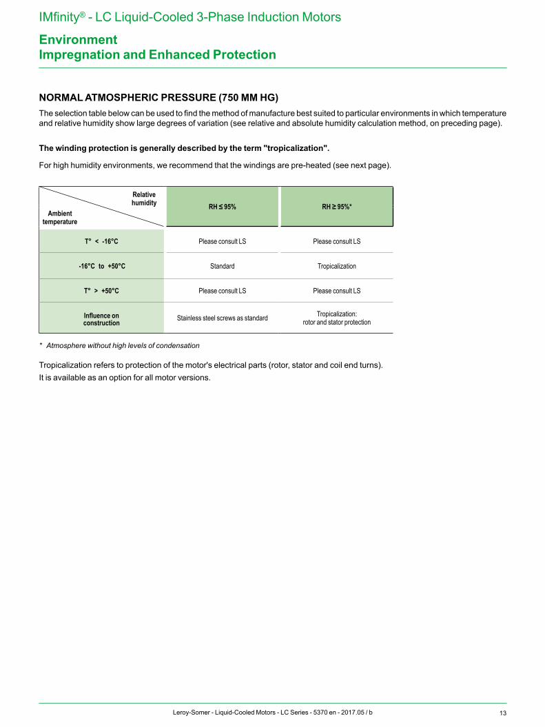
NORMAL ATMOSPHERIC PRESSURE (750 MM HG)The selection table below can be used to find the method of manufacture best suited to particular environments in which temperature and relative humidity show large degrees of variation (see relative and absolute humidity calculation method, on preceding page).
The winding protection is generally described by the term "tropicalization".
For high humidity environments, we recommend that the windings are pre-heated (see next page).
Relative humidity RH ≤ 95% RH ≥ 95%*
Ambient temperature
T° < -16°C Please consult LS Please consult LS
-16°C to +50°C Standard Tropicalization
T° > +50°C Please consult LS Please consult LS
Influence onconstruction Stainless steel screws as standard Tropicalization:
rotor and stator protection
* Atmosphere without high levels of condensation
Tropicalization refers to protection of the motor's electrical parts (rotor, stator and coil end turns).It is available as an option for all motor versions.
Impregnation and Enhanced Protection
14 Leroy-Somer - Liquid-Cooled Motors - LC Series - 5370 en - 2017.05 / b
IMfinity® - LC Liquid-Cooled 3-Phase Induction Motors
EnvironmentHeating
SPACE HEATERSSevere climatic conditions may require the use of space heaters (fitted to the motor windings) which serve to maintain the average temperature of the motor, provide trouble-free starting, and eliminate problems caused by condensation (loss of insulation).
The heater supply wires are brought out to a terminal block in the motor's auxiliary terminal box.
The heaters must be switched off while the motor is running.
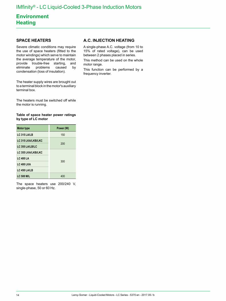
Table of space heater power ratings by type of LC motor
Motor type Power (W)
LC 315 LA/LB 150
LC 315 LKA/LKB/LKC200
LC 355 LA/LB/LC
LC 355 LKA/LKB/LKC
300LC 400 LA
LC 400 LKA
LC 450 LA/LB
LC 500 M/L 400
The space heaters use 200/240 V, single-phase, 50 or 60 Hz.
A.C. INJECTION HEATINGA single-phase A.C. voltage (from 10 to 15% of rated voltage), can be used between 2 phases placed in series.This method can be used on the whole motor range.This function can be performed by a frequency inverter.
15Leroy-Somer - Liquid-Cooled Motors - LC Series - 5370 en - 2017.05 / b
IMfinity® - LC Liquid-Cooled 3-Phase Induction Motors
EnvironmentExternal Finish
Surface protection is defined in standard ISO 12944. This standard defines the expected life of a paint system until the first major application of maintenance paint. Durability is not guaranteed.Standard EN ISO 12944 is divided into 8 parts. Part 2 discusses the classification of environments.Leroy-Somer motors are protected with a range of surface finishes.Surfaces receive appropriate special treatments, as shown below.
Leroy-Somer standard paint color reference:
PREPARATION OF SURFACESSurface Parts Surface treatment
Cast iron End shields Shot blasting + Primer
SteelAccessories Phosphate treatment + Primer
Terminal boxes - Fan covers - End shields Electrostatic painting or Epoxy powder
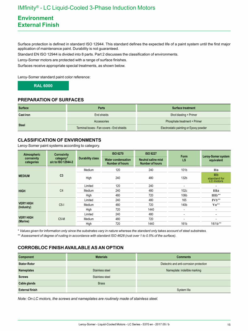
CLASSIFICATION OF ENVIRONMENTSLeroy-Somer paint systems according to category.
Atmospheric corrosivity categories
Corrosivity category*
a/c to ISO 12944-2Durability class
ISO 6270 ISO 9227Form
LSLeroy-Somer system
equivalentWater condensationNumber of hours
Neutral saline mistNumber of hours
MEDIUM C3Medium 120 240 101b IIa
High 240 480 132bIIb
standard for LC motors
HIGH C4Limited 120 240 - -Medium 240 480 102c IIIa
High 480 720 106b IIIb**
VERY HIGH(Industry) C5-I
Limited 240 480 165 IVb**Medium 480 720 140b Ve**
High 720 1440 - -
VERY HIGH(Marine) C5-M
Limited 240 480 - -Medium 480 720 - -
High 720 1440 161b 161b**
* Values given for information only since the substrates vary in nature whereas the standard only takes account of steel substrates.** Assessment of degree of rusting in accordance with standard ISO 4628 (rust over 1 to 0.5% of the surface).
CORROBLOC FINISH AVAILABLE AS AN OPTION
Component Materials Comments
Stator-Rotor Dielectric and anti-corrosion protection
Nameplates Stainless steel Nameplate: indelible marking
Screws Stainless steel
Cable glands Brass
External finish System IIIa
Note: On LC motors, the screws and nameplates are routinely made of stainless steel.
RAL 6000
16 Leroy-Somer - Liquid-Cooled Motors - LC Series - 5370 en - 2017.05 / b
IMfinity® - LC Liquid-Cooled 3-Phase Induction Motors
EnvironmentInterference Suppression and Protection of People
AIRBORNE INTERFERENCEEMISSIONFor standard motors, the housing acts as an electromagnetic screen, reducing electromagnetic emissions measured at 0.25 meters from the motor to approximately 5 gauss (5 x 10⁻⁴ T).However, electromagnetic emissions can be noticeably reduced by a specially-constructed stainless steel shaft.
IMMUNITYThe construction of the motor housings isolates external electromagnetic sources to the extent that any field penetrating the casing and magnetic circuit will be too weak to interfere with the operation of the motor.
POWER SUPPLY INTERFERENCEThe use of electronic systems for starting, variable speed control or power supply can create harmonics on the supply lines that may interfere with operation of the machines. These phenomena are taken into account in determining the machine dimensions, which act as quenching chokes in this respect.
The IEC 61000 standard, currently in preparation, will define permissible rejection and immunity rates: only then will machines for general distribution (especially single-phase motors and commutator motors) have to be fitted with suppression systems.Three-phase squirrel cage machines do not in themselves produce interference of this type. A.C. supply connection equipment (contactors) may, however, need interference protection.
APPLICATION OF DIRECTIVE 2004/108/EC CONCERNING ELECTROMAGNETIC COMPATIBILITY (EMC) a - for motors onlyAccording to amendment 1 of IEC 60034-1, induction motors are not transmitters and do not produce interference (via carried or airborne signals) and therefore conform inherently to the essential requirements of the EMC directives.
b - for motors supplied by inverters (at fixed or variable frequency)In this case, the motor is only a sub-assembly of a device which the system builder must ensure conforms to the essential requirements of the EMC directives.
APPLICATION OF LOW VOLTAGE DIRECTIVE 2006/95/ECAll motors are subject to this directive. The main requirements concern the protection of people, animals and property against risks caused by operation of the motors (see the commissioning and maintenance manual for precautions to be taken).
APPLICATION OF MACHINERY DIRECTIVE 2006/42/ECAll motors are designed to be integrated in a device subject to the machinery directive.
MARKING OF PRODUCTSThe fact that motors comply with the essential requirements of the Directives is shown by the CE mark on their nameplates and/or packaging and documentation.
17Leroy-Somer - Liquid-Cooled Motors - LC Series - 5370 en - 2017.05 / b
IMfinity® - LC Liquid-Cooled 3-Phase Induction Motors
ConstructionBearings and Bearing Life
DEFINITIONSLOAD RATINGSStatic load rating Co:This is the load for which permanent deformation at point of contact between a bearing race and the ball (or roller) with the heaviest load reaches 0.01% of the diameter of the ball (or roller).Dynamic load rating C:This is the load (constant in intensity and direction) for which the nominal lifetime of the bearing will reach 1 million revolutions.The static load rating Co and dynamic load rating C are obtained for each bearing by following the method in ISO 281.
LIFETIMEThe lifetime of a bearing is the number of revolutions (or number of operating hours at a constant speed) that the bearing can accomplish before the first signs of fatigue (spalling) begin to appear on a ring, ball or roller.Nominal lifetime L10hAccording to the ISO recommendations, the nominal lifetime is the length of time completed or exceeded by 90% of apparently identical bearings operating under the conditions specified by the manufacturer.
Note: The majority of bearings last much longer than the nominal lifetime; the average lifetime achieved or exceeded by 50% of bearings is around 5 times longer than the nominal lifetime.
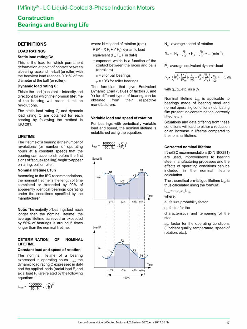
DETERMINATION OF NOMINAL LIFETIMEConstant load and speed of rotationThe nominal lifetime of a bearing expressed in operating hours L10h, the dynamic load rating C expressed in daN and the applied loads (radial load Fr and axial load Fa) are related by the following equation:
L10h =
Nm =
Pm= 1000000
60 Nm.----------------------- C
Pm----( )p.
L10h = 1000000
60 N.----------------------- C
P----( )p. N1
q1100---------- N2
q2100---------- … min 1–( )+.+.
P1P N1
Nm------
q1100----- P2
P N2Nm------ q 2
100----- …++P daN( ). . . .( ) ( )
where N = speed of rotation (rpm)P (P = X Fr + Y Fa): dynamic loadequivalent (Fr, Fa, P in daN)p: exponent which is a function of the
contact between the races and balls (or rollers) p = 3 for ball bearingsp = 10/3 for roller bearings
The formulae that give Equivalent Dynamic Load (values of factors X and Y) for different types of bearing can be obtained from their respective manufacturers.
Variable load and speed of rotationFor bearings with periodically variable load and speed, the nominal lifetime is established using the equation:
L10h =
Nm =
Pm= 1000000
60 Nm.----------------------- C
Pm----( )p.
L10h = 1000000
60 N.----------------------- C
P----( )p. N1
q1100---------- N2
q2100---------- … min 1–( )+.+.
P1P N1
Nm------
q1100----- P2
P N2Nm------ q 2
100----- …++P daN( ). . . .( ) ( )
Nm: average speed of rotation
L10h =
Nm =
Pm= 1000000
60 Nm.----------------------- C
Pm----( )p.
L10h = 1000000
60 N.----------------------- C
P----( )p. N1
q1100---------- N2
q2100---------- … min 1–( )+.+.
P1P N1
Nm------
q1100----- P2
P N2Nm------ q 2
100----- …++P daN( ). . . .( ) ( )
Pm: average equivalent dynamic load
L10h =
Nm =
Pm= 1000000
60 Nm.----------------------- C
Pm----( )p.
L10h = 1000000
60 N.----------------------- C
P----( )p. N1
q1100---------- N2
q2100---------- … min 1–( )+.+.
P1P N1
Nm------
q1100----- P2
P N2Nm------ q 2
100----- …++P daN( ). . . .( ) ( )with q1, q2, etc. as a %
Nominal lifetime L10h is applicable to bearings made of bearing steel and normal operating conditions (lubricating film present, no contamination, correctly fitted, etc.).Situations and data differing from these conditions will lead to either a reduction or an increase in lifetime compared to the nominal lifetime.
Corrected nominal lifetimeIf the ISO recommendations (DIN ISO 281) are used, improvements to bearing steel, manufacturing processes and the effects of operating conditions can be included in the nominal lifetime calculation.The theoretical pre-fatigue lifetime Lnah is thus calculated using the formula:Lnah = a1 a2 a3 L10h
where:a1: failure probability factora2: factor for thecharacteristics and tempering of the steela3: factor for the operating conditions (lubricant quality, temperature, speed of rotation, etc.).
Speed N
NmN1 N4
N2
N3
Load P
PmP1
P4
P2
P3
100%
q1% q2% q3% q4%
q1% q2% q3% q4%
Time
Time
18 Leroy-Somer - Liquid-Cooled Motors - LC Series - 5370 en - 2017.05 / b
IMfinity® - LC Liquid-Cooled 3-Phase Induction Motors
ConstructionLubrication and Maintenance of Bearings
ROLE OF THE LUBRICANTThe principal role of the lubricant is to avoid direct contact between the metal parts in motion: balls or rollers, slip-rings, cages, etc. It also protects the bearing against wear and corrosion.
The quantity of lubricant needed by a bearing is normally quite small. There should be enough to provide good lubrication without undesirable overheating. As well as lubrication itself and the operating temperature, the amount of lubricant should be judged by considerations such as sealing and heat dissipation.
The lubricating power of a grease or an oil lessens with time owing to mechanical constraints and straightforward aging. Used or contaminated lubricants should therefore be replaced or topped up with new lubricant at regular intervals.
Bearings can be lubricated with grease, oil or, in certain cases, with a solid lubricant.
GREASINGA lubricating grease can be defined as a product of semi-fluid consistency obtained by the dispersion of a thickening agent in a lubricating fluid and that may contain several additives to give it particular properties.
Composition of a greaseBase oil: 85 to 97%Thickener: 3 to 15%Additives: 0 to 12%
THE BASE OIL LUBRICATESThe oil making up the grease is of prime importance. It is the oil that lubricates the moving parts by coating them with a protective film which prevents direct contact. The thickness of the lubricating film is directly linked to the viscosity of the oil, and the viscosity itself depends on temperature. The two main types used to make grease are mineral oils and synthetic oils. Mineral oils are suitable for normal applications in a range of temperatures from -30°C to +150°C.Synthetic oils have the advantage of being effective in severe conditions (extreme variations of temperature, harsh chemical environments, etc.).
THE THICKENER GIVES THE GREASE CONSISTENCYThe more thickener a grease contains, the “harder” it will be. Grease consistency varies with the temperature. In falling temperatures, the grease hardens progressively, and the opposite happens when temperatures rise.
The consistency of a grease can be quantified using the NLGI (National Lubricating Grease Institute) classification. There are 9 NLGI grades, from 000 for the softest greases up to 6 for the hardest. Consistency is expressed by the depth to which a cone can be driven into a grease maintained at 25°C.If we only consider the chemical nature of the thickener, lubricating greases fall into three major categories:
• Conventional greases with a metallic soap base (calcium, sodium, aluminum, lithium). Lithium soaps have several advantages over other metallic soaps: a high melting point (180° to 200°), good mechanical stability and good water-resistant properties.
• Greases with a complex soap base. The main advantage of this type of soap is a very high melting point (over 250°C).
• Soapless greases. The thickener is an inorganic compound, such as clay. Their main property is the absence of a melting point, which makes them practically non-liquefying.
ADDITIVES IMPROVE SOME PROPERTIES OF GREASESAdditives fall into two types, depending on whether or not they are soluble in the base oil.
The most common insoluble additives - graphite, molybdenum disulphide, talc, mica, etc., improve the friction characteristics between metal surfaces. They are therefore used in applications where heavy pressure is required.
The soluble additives are the same as those used in lubricating oils: antioxidants, anti-rust agents, etc.
LUBRICATION TYPEThe bearings are lubricated with a polyurea soap-based grease.
19Leroy-Somer - Liquid-Cooled Motors - LC Series - 5370 en - 2017.05 / b
IMfinity® - LC Liquid-Cooled 3-Phase Induction Motors
OperationDuty Cycle - Definitions
DUTY CYCLES(IEC 60034-1)
The typical duty cycles are described below:
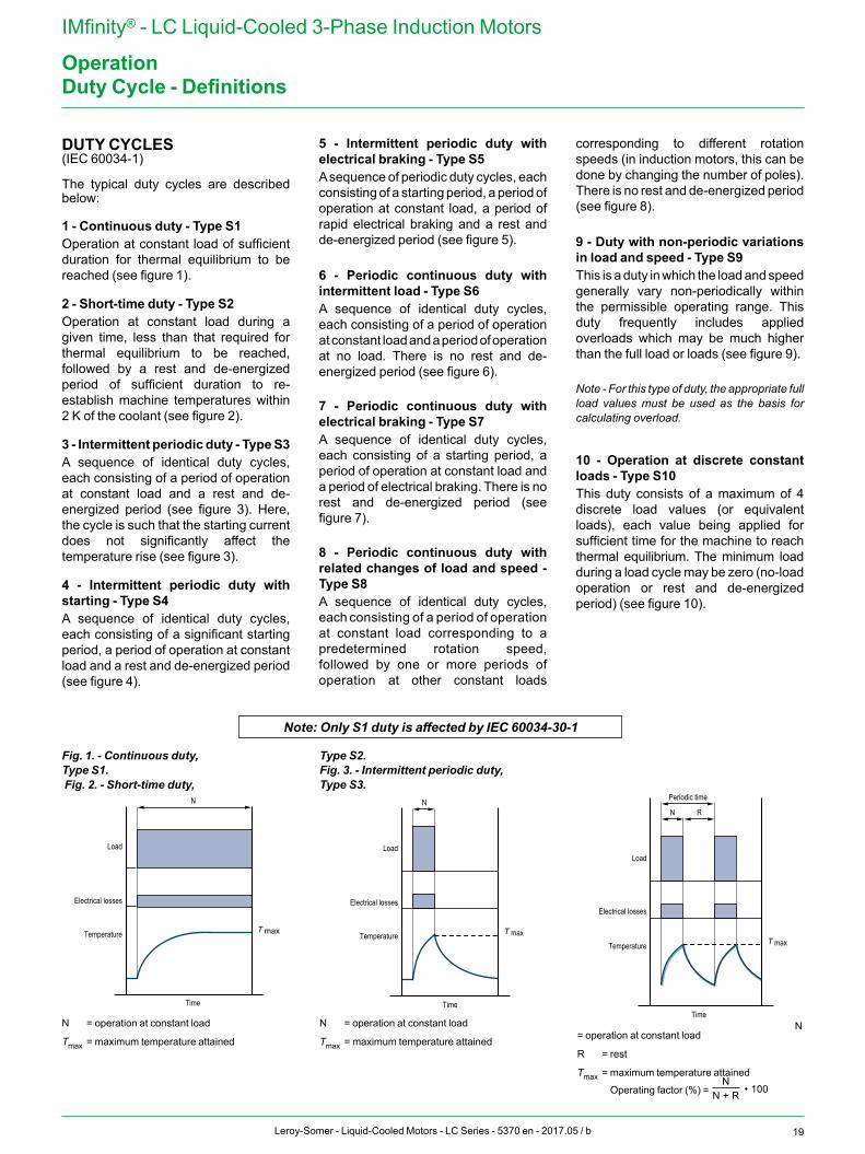
1 - Continuous duty - Type S1Operation at constant load of sufficient duration for thermal equilibrium to be reached (see figure 1).
2 - Short-time duty - Type S2Operation at constant load during a given time, less than that required for thermal equilibrium to be reached, followed by a rest and de-energized period of sufficient duration to re-establish machine temperatures within 2 K of the coolant (see figure 2).
3 - Intermittent periodic duty - Type S3A sequence of identical duty cycles, each consisting of a period of operation at constant load and a rest and de-energized period (see figure 3). Here, the cycle is such that the starting current does not significantly affect the temperature rise (see figure 3).
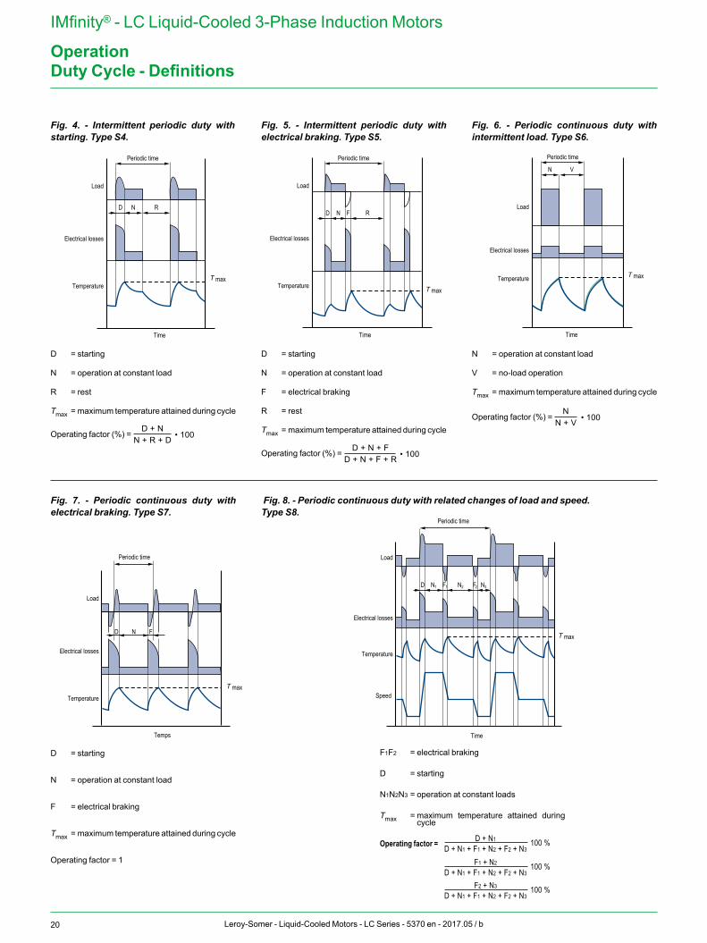
4 - Intermittent periodic duty with starting - Type S4A sequence of identical duty cycles, each consisting of a significant starting period, a period of operation at constant load and a rest and de-energized period (see figure 4).
5 - Intermittent periodic duty with electrical braking - Type S5 A sequence of periodic duty cycles, each consisting of a starting period, a period of operation at constant load, a period of rapid electrical braking and a rest and de-energized period (see figure 5).
6 - Periodic continuous duty with intermittent load - Type S6A sequence of identical duty cycles, each consisting of a period of operation at constant load and a period of operation at no load. There is no rest and de-energized period (see figure 6).
7 - Periodic continuous duty with electrical braking - Type S7A sequence of identical duty cycles, each consisting of a starting period, a period of operation at constant load and a period of electrical braking. There is no rest and de-energized period (see figure 7).
8 - Periodic continuous duty with related changes of load and speed - Type S8A sequence of identical duty cycles, each consisting of a period of operation at constant load corresponding to a predetermined rotation speed, followed by one or more periods of operation at other constant loads
corresponding to different rotation speeds (in induction motors, this can be done by changing the number of poles). There is no rest and de-energized period (see figure 8).
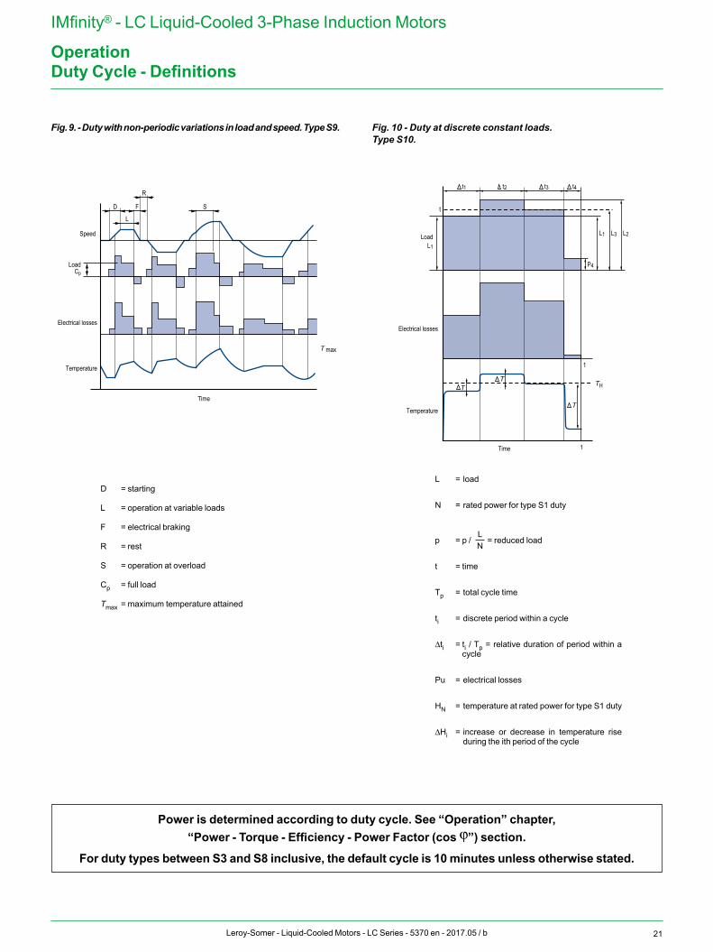
9 - Duty with non-periodic variations in load and speed - Type S9This is a duty in which the load and speed generally vary non-periodically within the permissible operating range. This duty frequently includes applied overloads which may be much higher than the full load or loads (see figure 9).
Note - For this type of duty, the appro priate full load values must be used as the basis for calculating overload.
10 - Operation at discrete constant loads - Type S10This duty consists of a maximum of 4 discrete load values (or equivalent loads), each value being applied for sufficient time for the machine to reach thermal equilibrium. The minimum load during a load cycle may be zero (no-load operation or rest and de-energized period) (see figure 10).
Load
Electrical losses
Temperature
Time
N
T max
Load
Electrical losses
Temperature
Time
N
T max
Load
Electrical losses
Temperature
Time
N
T max
R
Periodic time
Note: Only S1 duty is affected by IEC 60034-30-1
N = operation at constant load
Tmax = maximum temperature attained
N = operation at constant load
Tmax = maximum temperature attainedN
= operation at constant load
R = rest
Tmax = maximum temperature attained
Operating factor (%) = N
• 100N + R
N• 100N + V
D + N1 100 %D + N1 + F1 + N2 + F2 + N3
F1 + N2 100 %D + N1 + F1 + N2 + F2 + N3
F2 + N3 100 %D + N1 + F1 + N2 + F2 + N3
LN
D + N• 100N + R + D
D + N + F• 100D + N + F + R
Fig. 1. - Continuous duty,Type S1. Fig. 2. - Short-time duty,
Type S2.Fig. 3. - Intermittent periodic duty,Type S3.
20 Leroy-Somer - Liquid-Cooled Motors - LC Series - 5370 en - 2017.05 / b
IMfinity® - LC Liquid-Cooled 3-Phase Induction Motors
Operation
F1F2 = electrical braking
D = starting
N1N2N3 = operation at constant loads
Tmax = maximum temperature attained during cycle
Operating factor =
N• 100N + R
N• 100N + V
D + N1 100 %D + N1 + F1 + N2 + F2 + N3
F1 + N2 100 %D + N1 + F1 + N2 + F2 + N3
F2 + N3 100 %D + N1 + F1 + N2 + F2 + N3
LN
D + N• 100N + R + D
D + N + F• 100D + N + F + R
D = starting
N = operation at constant load
F = electrical braking
Tmax = maximum temperature attained during cycle
Operating factor = 1
Load
Electrical losses
Temperature
Temps
N F
Periodic time
D
Load
Electrical losses
Temperature
Time
Periodic time
D
Speed T max
N1
T max
N2F1 F2 N3
Duty Cycle - Definitions
Fig. 4. - Intermittent periodic duty with starting. Type S4.
Fig. 5. - Intermittent periodic duty with electrical braking. Type S5.
Fig. 6. - Periodic continuous duty with intermittent load. Type S6.
D = starting
N = operation at constant load
R = rest
Tmax = maximum temperature attained during cycle
Operating factor (%) = N
• 100N + R
N• 100N + V
D + N1 100 %D + N1 + F1 + N2 + F2 + N3
F1 + N2 100 %D + N1 + F1 + N2 + F2 + N3
F2 + N3 100 %D + N1 + F1 + N2 + F2 + N3
LN
D + N• 100N + R + D
D + N + F• 100D + N + F + R
D = starting
N = operation at constant load
F = electrical braking
R = rest
Tmax = maximum temperature attained during cycle
Operating factor (%) = N
• 100N + R
N• 100N + V
D + N1 100 %D + N1 + F1 + N2 + F2 + N3
F1 + N2 100 %D + N1 + F1 + N2 + F2 + N3
F2 + N3 100 %D + N1 + F1 + N2 + F2 + N3
LN
D + N• 100N + R + D
D + N + F• 100D + N + F + R
N = operation at constant load
V = no-load operation
Tmax = maximum temperature attained during cycle
Operating factor (%) =
N• 100N + R
N• 100N + V
D + N1 100 %D + N1 + F1 + N2 + F2 + N3
F1 + N2 100 %D + N1 + F1 + N2 + F2 + N3
F2 + N3 100 %D + N1 + F1 + N2 + F2 + N3
LN
D + N• 100N + R + D
D + N + F• 100D + N + F + R
Fig. 7. - Periodic continuous duty with electrical braking. Type S7.
Fig. 8. - Periodic continuous duty with related changes of load and speed.Type S8.
Load
Electrical losses
Temperature
Time
N R
Periodic time
D
T max
Load
Electrical losses
Temperature
Time
N R
Periodic time
D F
T max
Load
Electrical losses
Temperature
Time
N V
Periodic time
T max
21Leroy-Somer - Liquid-Cooled Motors - LC Series - 5370 en - 2017.05 / b
IMfinity® - LC Liquid-Cooled 3-Phase Induction Motors
OperationDuty Cycle - Definitions
Fig. 9. - Duty with non-periodic variations in load and speed. Type S9. Fig. 10 - Duty at discrete constant loads.Type S10.
D = starting
L = operation at variable loads
F = electrical braking
R = rest
S = operation at overload
Cp = full load
Tmax = maximum temperature attained
L = load
N = rated power for type S1 duty
p = p /
N• 100N + R
N• 100N + V
D + N1 100 %D + N1 + F1 + N2 + F2 + N3
F1 + N2 100 %D + N1 + F1 + N2 + F2 + N3
F2 + N3 100 %D + N1 + F1 + N2 + F2 + N3
LN
D + N• 100N + R + D
D + N + F• 100D + N + F + R
= reduced load
t = time
Tp = total cycle time
ti = discrete period within a cycle
Δti = ti / Tp = relative duration of period within a cycle
Pu = electrical losses
HN = temperature at rated power for type S1 duty
ΔHi = increase or decrease in temperature rise during the ith period of the cycle
Speed
Electrical losses
Temperature
Time
L
Load
FD
R
S
1
TT
TTemperature
1
Electrical losses
t
Load
Time
Cp
T max
TH
t1
L1
L2L3
t2 t3 t4
P4
L1
Power is determined according to duty cycle. See “Operation” chapter,“Power - Torque - Efficiency - Power Factor (cos j”) section.
For duty types between S3 and S8 inclusive, the default cycle is 10 minutes unless otherwise stated.
22 Leroy-Somer - Liquid-Cooled Motors - LC Series - 5370 en - 2017.05 / b
IMfinity® - LC Liquid-Cooled 3-Phase Induction Motors
OperationSupply Voltage
REGULATIONS AND STANDARDSThe IEC 60038 standard gives the European reference voltage as 230/400 V three-phase and 230 V single-phase, with a tolerance of ±10%.The tolerances usually permitted for power supply sources are indicated below:
• Maximum voltage drop between customer delivery point and customer usage point: 4%.
• Variation in frequency around the rated frequency:- continuous operation: ±1%- transient state: ±2%
• Three-phase Mains supply phase voltage imbalance:- zero-sequence component and/or negative phase sequence component compared to positive phase sequence component: < 2%
The motors in this catalog are designed for use on the European power supply of 400 V ±10% - 50 Hz.All other voltages and frequencies are available on request.
EFFECTS ON MOTOR PERFORMANCEVOLTAGE RANGEThe characteristics of motors will of course vary with a corresponding variation in voltage of ±10% around the rated value.
An approximation of these variations is given in the table below.
Voltage variation as a %UN-10% UN-5% UN UN+5% UN+10%
Torque curve 0.81 0.90 1 1.10 1.21Slip 1.23 1.11 1 0.91 0.83Rated current 1.10 1.05 1 0.98 0.98Rated efficiency 0.97 0.98 1 1.00 0.98Rated power factor (cos j) 1.03 1.02 1 0.97 0.94Starting current 0.90 0.95 1 1.05 1.10Nominal temperature rise 1.18 1.05* 1 1* 1.10P (Watt) no-load 0.85 0.92 1 1.12 1.25Q (reactive V A) no-load 0.81 0.9 1 1.1 1.21
* According to standard IEC 60034-1, the additional temperature rise must not exceed 10 K within ±5% of UN.
23Leroy-Somer - Liquid-Cooled Motors - LC Series - 5370 en - 2017.05 / b
IMfinity® - LC Liquid-Cooled 3-Phase Induction Motors
OperationSupply Voltage
SIMULTANEOUS VARIATION OF VOLTAGE AND FREQUENCYWithin the tolerances defined in IEC guide 106, machine input and performance are unaffected if the variations are of the same polarity and the voltage/frequency ratio U/f remains constant.If this is not the case, variations in performance are significant and require the machine specification to be changed.
Variation in main motor parameters (approx.) within the limits defined in IEC Guide 106.
U/f Pu M N Cos j Efficiency
Constant f’Puf
400U’
u’ / uPu( )2
f / f’u’ / uM( )2
f / f’f’Nf
M f’Puf
400U’
u’ / uPu( )2
f / f’u’ / uM( )2
f / f’f’Nf
cos j unchanged
Efficiency unchanged
Variablef’Puf
400U’
u’ / uPu( )2
f / f’u’ / uM( )2
f / f’f’Nf
f’Puf
400U’
u’ / uPu( )2
f / f’u’ / uM( )2
f / f’f’Nf
f’Puf
400U’
u’ / uPu( )2
f / f’u’ / uM( )2
f / f’f’Nf
Dependent on the machine saturation state
M = minimum and maximum values of starting torque.
USE OF 400 V - 50 HZ MOTORS ON 460 V - 60 HZ SUPPLIESFor output power at 60 Hz equal to output power at 50 Hz, the main characteristics are modified according to the following variations:- Efficiency increases by 0.5 - 1.5%- Power factor decreases by 0.5 to 1.5%
- Rated current decreases by 0 to 5%- IS/IN increases by around 10%- Slip and rated torque MN, MD/MN, M/MN remain more or less constant.
Comment:For the North American markets, a different type of construction is needed to comply with the regulatory requirements.
USE ON SUPPLIES WITH U’ VOLTAGES different from the voltages in the characteristics tables
In this case, the machine windings should be adapted.As a result, only the current values will be changed and become:
I’ = I400 V x f’Puf
400U’
u’ / uPu( )2
f / f’u’ / uM( )2
f / f’f’Nf
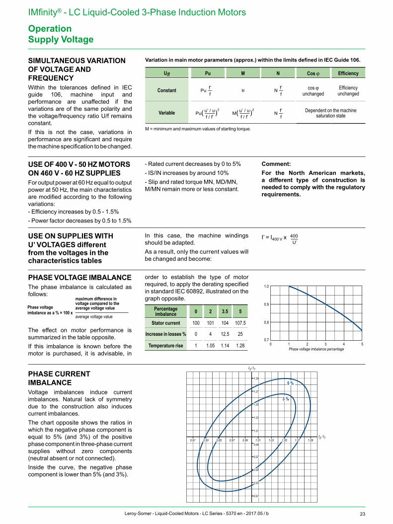
PHASE VOLTAGE IMBALANCEThe phase imbalance is calculated as follows:
The effect on motor performance is summarized in the table opposite.If this imbalance is known before the motor is purchased, it is advisable, in
order to establish the type of motor required, to apply the derating specified in standard IEC 60892, illustrated on the graph opposite.
Percentage imbalance 0 2 3.5 5
Stator current 100 101 104 107.5
Increase in losses % 0 4 12.5 25
Temperature rise 1 1.05 1.14 1.28 0 1 2 3 4 5
0.8
0.9
1.0
0.7
Phase voltage imbalance percentage
Dera
ting
facto
r
PHASE CURRENT IMBALANCEVoltage imbalances induce current imbalances. Natural lack of symmetry due to the construction also induces current imbalances.The chart opposite shows the ratios in which the negative phase component is equal to 5% (and 3%) of the positive phase component in three-phase current supplies without zero components (neutral absent or not connected).Inside the curve, the negative phase component is lower than 5% (and 3%).
0.91
0.97
0.99
1.01
1.03
1.07
1.09
0.990.970.91 1.091.031.01I2 / I1
I3 / I1
5 %
3 %
0.93
0.95
1.071.050.950.93
1.05
Phase voltage imbalance as a % = 100 x
maximum difference in voltage compared to the average voltage value
average voltage value
24 Leroy-Somer - Liquid-Cooled Motors - LC Series - 5370 en - 2017.05 / b
IMfinity® - LC Liquid-Cooled 3-Phase Induction Motors
OperationInsulation Class - Temperature Rise and Thermal Reserve
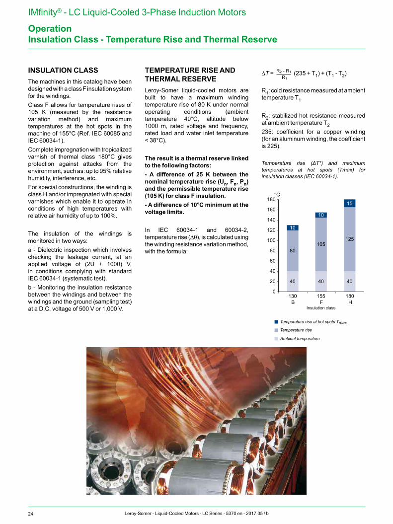
INSULATION CLASSThe machines in this catalog have been designed with a class F insulation system for the windings.Class F allows for temperature rises of 105 K (measured by the resistance variation method) and maximum temperatures at the hot spots in the machine of 155°C (Ref. IEC 60085 and IEC 60034-1).Complete impregnation with tropicalized varnish of thermal class 180°C gives protection against attacks from the environment, such as: up to 95% relative humidity, interference, etc.For special constructions, the winding is class H and/or impregnated with special varnishes which enable it to operate in conditions of high temperatures with relative air humidity of up to 100%.
The insulation of the windings is monitored in two ways:a - Dielectric inspection which involves checking the leakage current, at an applied voltage of (2U + 1000) V, in conditions complying with standard IEC 60034-1 (systematic test).b - Monitoring the insulation resistance between the windings and between the windings and the ground (sampling test) at a D.C. voltage of 500 V or 1,000 V.
TEMPERATURE RISE AND THERMAL RESERVELeroy-Somer liquid-cooled motors are built to have a maximum winding temperature rise of 80 K under normal operating conditions (ambient temperature 40°C, altitude below 1000 m, rated voltage and frequency, rated load and water inlet temperature < 38°C).
The result is a thermal reserve linked to the following factors: - A difference of 25 K between the nominal temperature rise (Un, Fn, Pn) and the permissible temperature rise (105 K) for class F insulation.- A difference of 10°C minimum at the voltage limits.
In IEC 60034-1 and 60034-2, temperature rise (Δθ), is calculated using the winding resistance variation method, with the formula:
ΔT = R2 - R1
R1 (235 + T1) + (T1 - T2)
R1: cold resistance measured at ambient temperature T1
R2: stabilized hot resistance measured at ambient temperature T2235: coefficient for a copper winding (for an aluminum winding, the coefficient is 225).
Temperature rise (ΔT*) and maximum temperatures at hot spots (Tmax) for insulation classes (IEC 60034-1).
80
10
105
10
125
15
0130
B
°C
40
155F
180
Insulation class
Temperature rise at hot spots Tmax
H
40 4020
40
60
80
100
120
140
160
180
Temperature rise
Ambient temperature
25Leroy-Somer - Liquid-Cooled Motors - LC Series - 5370 en - 2017.05 / b
IMfinity® - LC Liquid-Cooled 3-Phase Induction Motors
OperationStarting Times and Starting Current
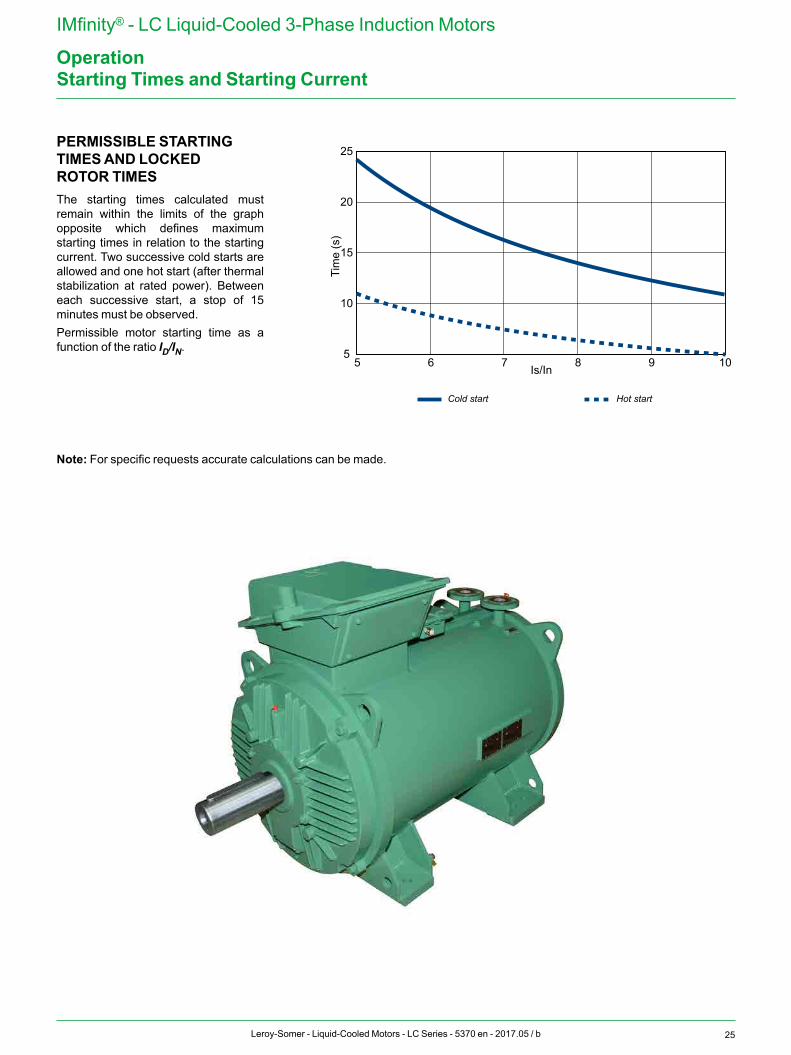
PERMISSIBLE STARTING TIMES AND LOCKED ROTOR TIMESThe starting times calculated must remain within the limits of the graph opposite which defines maximum starting times in relation to the starting current. Two successive cold starts are allowed and one hot start (after thermal stabilization at rated power). Between each successive start, a stop of 15 minutes must be observed.Permissible motor starting time as a function of the ratio ID/IN.
25
20
15
Tim
e (s
)
10
55 6 7 Is/In 8 9 10
Hot startCold start
Note: For specific requests accurate calculations can be made.
26 Leroy-Somer - Liquid-Cooled Motors - LC Series - 5370 en - 2017.05 / b
IMfinity® - LC Liquid-Cooled 3-Phase Induction Motors
OperationPower - Torque - Efficiency - Power Factor (Cos j)
DEFINITIONSThe output power (Pu) at the motor shaft is linked to the torque (M) by the equation:
Pu = M.ωwhere Pu is in W, M is in N.m, ω is in rad/s and where ω is expressed as a function of the speed of rotation in rpm by the equation:
ω = 2π.N/60The active power (P) drawn from the
A.C. supply is expressed as a function of the apparent power (S) and the reactive power (Q) by the equation:
PuP =η
Pcosφ =S
S = √P2 + Q2 √3
(S in VA, P in W and Q in VAR)
The power P is linked to the output power Pu by the equation:
PuP =η
Pcosφ =S
S = √P2 + Q2 √3
where η is the efficiency of the machine.
The output power Pu at the motor shaft is expressed as a function of the phase-to-phase A.C. supply voltage (U in Volts), of the line current absorbed (I in Amps) by the equation:
Pu = U.I. PuP =η
Pcosφ =S
S = √P2 + Q2 √3 . cosj . η
where cos j is the power factor found from the ratio:
PuP =η
Pcosφ =S
S = √P2 + Q2 √3
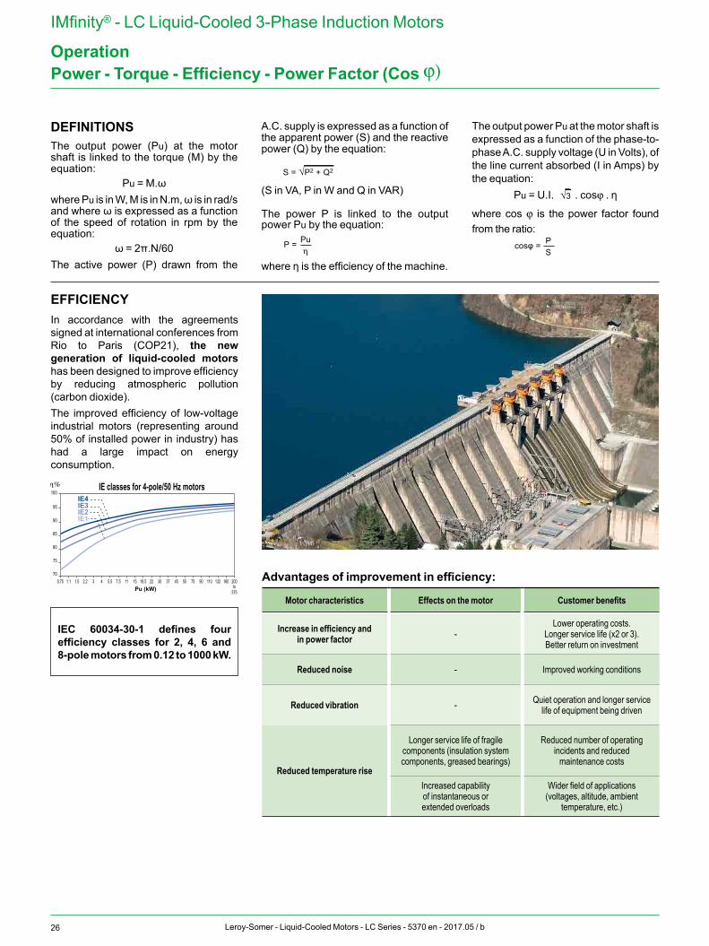
EFFICIENCYIn accordance with the agreements signed at international conferences from Rio to Paris (COP21), the new generation of liquid-cooled motors has been designed to improve efficiency by reducing atmospheric pollution (carbon dioxide).The improved efficiency of low-voltage industrial motors (representing around 50% of installed power in industry) has had a large impact on energy consumption.
100
95
90
85
80
75
700.75
η%
Pu (kW)1.1 1.5 2.2 3 4 5.5 7.5 11 15 18.5 22 30 37 45 55 75 90 110 132 160 200
375
IE3
IE classes for 4-pole/50 Hz motors
to
IE4
IE2IE1
Advantages of improvement in efficiency:
Motor characteristics Effects on the motor Customer benefits
Increase in efficiency and in power factor -
Lower operating costs.Longer service life (x2 or 3).Better return on investment
Reduced noise - Improved working conditions
Reduced vibration - Quiet operation and longer service life of equipment being driven
Reduced temperature rise
Longer service life of fragile components (insulation system components, greased bearings)
Reduced number of operating incidents and reduced
maintenance costs
Increased capability of instantaneous or extended overloads
Wider field of applications (voltages, altitude, ambient
temperature, etc.)
IEC 60034-30-1 defines four efficiency classes for 2, 4, 6 and 8-pole motors from 0.12 to 1000 kW.
27Leroy-Somer - Liquid-Cooled Motors - LC Series - 5370 en - 2017.05 / b
IMfinity® - LC Liquid-Cooled 3-Phase Induction Motors
OperationPower - Torque - Efficiency - Power Factor (Cos j)
RATED POWER PN IN RELATION TO DUTY CYCLEGENERAL RULES FOR STANDARD MOTORS
Pn=√n x td x [ID/In x P]2 + (3600 - n x td)P2u x fdm 3600
P =√Σ(P2i . ti) Σti
td = π . N . (Je + Jr)
30 Mmot - Mr
Em ≥ Ed + Ef
Ed = 1
(Je + Jr)(π . N)2x n + n x td√3UIdcosϕd 2 30
P =√Σn1(P2i . ti) = √P21 . t1 + P22 . t2... + P2n. tn Σn1ti t1 + t2 + ...tn
TIn2
Iterative calculation where:td(s) starting time achieved with
motor rated P(w)
n number of (equivalent) starts per hour
fdm (OF) operating factor (decimal)ID/In current demand for motor
rated PPu (w) motor output power during
the duty cycle OF (in decimal), operating
factorP (w) motor rated power selected
for the calculation
S1 OF = 1; n ≤ 4
S2 n = 1 operating life determined by specification (Sp)
S3 OF according to Sp; n ~ 0(no effect of starting on temperature rise)
S4 OF according to Sp; n according to Sp; td, Pu,P according to Sp
(replace n with 4n in the above formula)
S5 OF according to Sp; n = n starts+ 3 n braking operations = 4;
td, Pu, P according to Sp(replace n with 4n in the above formula)
S6
Pn=√n x td x [ID/In x P]2 + (3600 - n x td)P2u x fdm 3600
P =√Σ(P2i . ti) Σti
td = π . N . (Je + Jr)
30 Mmot - Mr
Em ≥ Ed + Ef
Ed = 1
(Je + Jr)(π . N)2x n + n x td√3UIdcosϕd 2 30
P =√Σn1(P2i . ti) = √P21 . t1 + P22 . t2... + P2n. tn Σn1ti t1 + t2 + ...tn
TIn2
S7 same formula as S5 but OF = 1S8 at high speed, same formula as S1
at low speed, same formula as S5S9 S8 duty formula after complete description
of cycle with OF on each speedS10 same formula as S6
In addition, see the warning regarding precautions to be taken. Variations in voltage and/or frequency greater than standard should also be taken into account. The application should also be taken into account (general at constant torque, centrifugal at quadratic torque, etc.).
DETERMINATION OF THE POWER IN INTERMITTENT DUTY CYCLES FOR ADAPTED MOTORSRMS POWER IN INTERMITTENT DUTYThis is the rated power absorbed by the driven machine, usually defined by the manufacturer.If the power absorbed by the machine varies during a cycle, the rms power P is calculated using the equation:
Pn=√n x td x [ID/In x P]2 + (3600 - n x td)P2u x fdm 3600
P =√Σ(P2i . ti) Σti
td = π . N . (Je + Jr)
30 Mmot - Mr
Em ≥ Ed + Ef
Ed = 1
(Je + Jr)(π . N)2x n + n x td√3UIdcosϕd 2 30
P =√Σn1(P2i . ti) = √P21 . t1 + P22 . t2... + P2n. tn Σn1ti t1 + t2 + ...tn
TIn2
if, during the working time the absorbed power is:
P1 for period t1
P2 for period t2 Pn for period tn
Power values lower than 0.5 PN are replaced by 0.5 PN in the calculation of rms power P (no-load operation is a special case).
Additionally, it is also necessary to check that for a particular motor of power PN:
- the actual starting time is at most equal to 5 seconds
- the maximum output of the cycle does not exceed twice the rated output power P
- there is still sufficient accelerating torque during the starting period
Load factor (LF)Expressed as a percentage, this is the ratio of the period of operating time with a load during the cycle to the total duration of the cycle where the motor is energized.
Operating factor (OF)Expressed as a percentage, this is the ratio of the motor power-on time during the cycle to the total cycle time, provided that the total cycle time is less than 10 minutes.
Starting classClass: n = nD + k.nF + k’.ninD: number of complete starts per hournF: number of electrical braking operations per hour
“Electrical braking” means any braking directly involving the stator winding or the rotor winding:- Regenerative braking (with frequency controller, multipole motor, etc.)
- Reverse-current braking (the most commonly used)
- D.C. injection brakingni: number of pulses (incomplete starts up to a third of maximum speed) per hour
k and k’ are constants determined as follows:
k k’Cage induction motors 3 0.5
- Reversing the direction of rotation involves braking (usually electrical) and starting.
- Braking with Leroy-Somer electromechanical brakes, as with any other brakes that are independent of the motor, does not constitute electrical braking in the sense described above.
28 Leroy-Somer - Liquid-Cooled Motors - LC Series - 5370 en - 2017.05 / b
IMfinity® - LC Liquid-Cooled 3-Phase Induction Motors
OperationPower - Torque - Efficiency - Power Factor (Cos j)
CALCULATING DERATINGInput criteria (load)- rms power during the cycle = P- Moment of inertia related to the speed of the motor: Je
- Operating factor = OF- Class of starts per hour = n- Resistive torque during starting = Mr
Selection in catalog- Motor rated power = PN- Starting current Id, cosjD- Moment of inertia of rotor Jr- Average starting torque Mmot- Efficiency at PN(ηPN) and at P(ηP)
Calculations- Starting time:
Pn=√n x td x [ID/In x P]2 + (3600 - n x td)P2u x fdm 3600
P =√Σ(P2i . ti) Σti
td = π . N . (Je + Jr)
30 Mmot - Mr
Em ≥ Ed + Ef
Ed = 1
(Je + Jr)(π . N)2x n + n x td√3UIdcosϕd 2 30
P =√Σn1(P2i . ti) = √P21 . t1 + P22 . t2... + P2n. tn Σn1ti t1 + t2 + ...tn
TIn2
- Cumulative starting time per hour:n x td
- Energy to be dissipated per hour during starts = sum of the energy dissipated in the rotor (= inertia acceleration energy) and the energy dissipated in the stator during the cumulative starting time per hour:
Pn=√n x td x [ID/In x P]2 + (3600 - n x td)P2u x fdm 3600
P =√Σ(P2i . ti) Σti
td = π . N . (Je + Jr)
30 Mmot - Mr
Em ≥ Ed + Ef
Ed = 1
(Je + Jr)(π . N)2x n + n x td√3UIdcosϕd 2 30
P =√Σn1(P2i . ti) = √P21 . t1 + P22 . t2... + P2n. tn Σn1ti t1 + t2 + ...tn
TIn2
- Energy to be dissipated during operation Eƒ = P. (1 - ηP) . [(OF) x 3600 - n x td]
- Energy that the motor can dissipate at rated power with the Operating Factor for Intermittent Duty. Em = (OF) 3600 . PN.(1 - ηPN)(The heat dissipated when the motor is at rest can be ignored).
Dimensioning is correct if the following relationship is verified =
Pn=√n x td x [ID/In x P]2 + (3600 - n x td)P2u x fdm 3600
P =√Σ(P2i . ti) Σti
td = π . N . (Je + Jr)
30 Mmot - Mr
Em ≥ Ed + Ef
Ed = 1
(Je + Jr)(π . N)2x n + n x td√3UIdcosϕd 2 30
P =√Σn1(P2i . ti) = √P21 . t1 + P22 . t2... + P2n. tn Σn1ti t1 + t2 + ...tn
TIn2
If the sum of Ed + Eƒ is lower than 0.75 Em, check whether a motor with the next lowest power would be more suitable.
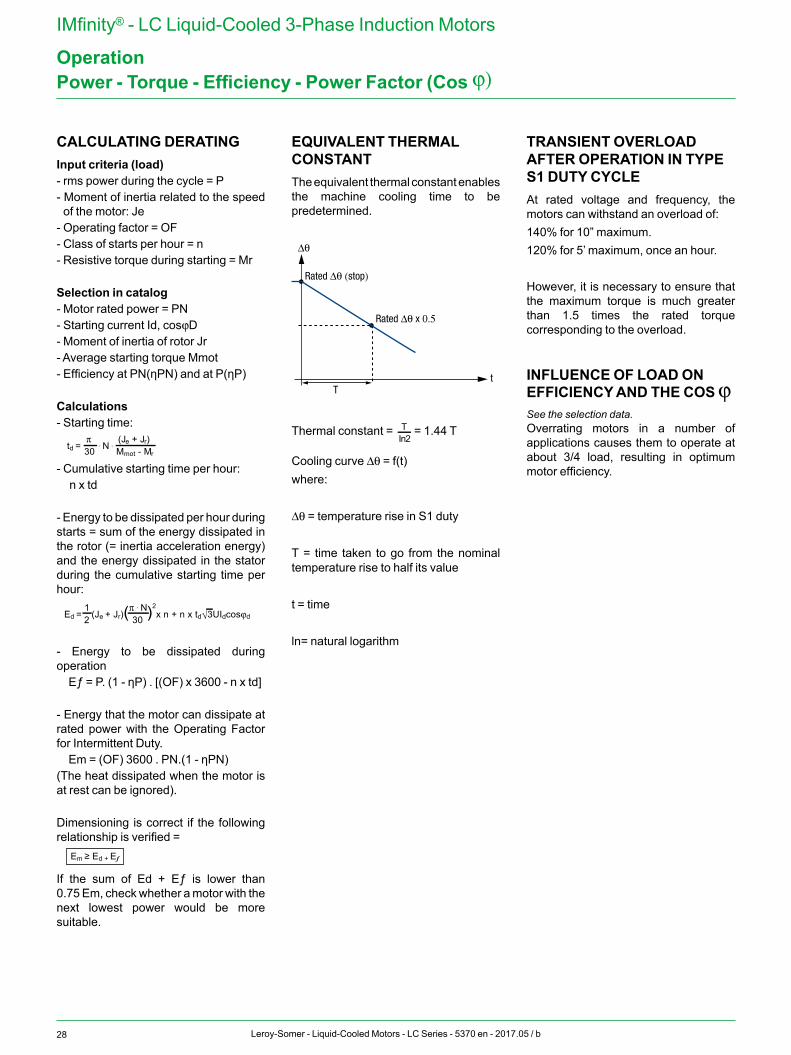
EQUIVALENT THERMAL CONSTANTThe equivalent thermal constant enables the machine cooling time to be predetermined.
∆θ
Rated ∆θ (stop)
Rated ∆θ x 0.5
Tt
Thermal constant =
Pn=√n x td x [ID/In x P]2 + (3600 - n x td)P2u x fdm 3600
P =√Σ(P2i . ti) Σti
td = π . N . (Je + Jr)
30 Mmot - Mr
Em ≥ Ed + Ef
Ed = 1
(Je + Jr)(π . N)2x n + n x td√3UIdcosϕd 2 30
P =√Σn1(P2i . ti) = √P21 . t1 + P22 . t2... + P2n. tn Σn1ti t1 + t2 + ...tn
TIn2
= 1.44 T
Cooling curve Δθ = f(t)where:
Δθ = temperature rise in S1 duty
T = time taken to go from the nominal temperature rise to half its value
t = time
ln= natural logarithm
TRANSIENT OVERLOAD AFTER OPERATION IN TYPE S1 DUTY CYCLEAt rated voltage and frequency, the motors can withstand an overload of:140% for 10” maximum.120% for 5’ maximum, once an hour.
However, it is necessary to ensure that the maximum torque is much greater than 1.5 times the rated torque corresponding to the overload.
INFLUENCE OF LOAD ON EFFICIENCY AND THE COS jSee the selection data.Overrating motors in a number of applications causes them to operate at about 3/4 load, resulting in optimum motor efficiency.
29Leroy-Somer - Liquid-Cooled Motors - LC Series - 5370 en - 2017.05 / b
IMfinity® - LC Liquid-Cooled 3-Phase Induction Motors
OperationNoise Level
NOISE EMITTED BY ROTATING MACHINESIn a compressible medium, the mechanical vibrations of an elastic body create pressure waves which are characterized by their amplitude and frequency. The pressure waves constitute an audible noise if they have a frequency of between 16 Hz and 16,000 Hz.
Noise is measured by a microphone linked to a frequency analyzer. Measurements are taken in an anechoic chamber on machines at no-load, and a sound pressure level Lp or a sound power level Lw can then be established. Measurement can also be carried out in situ on machines which may be on-load, using an acoustic intensity meter which can differentiate between sound sources and identify the sound emissions from the machine.
The concept of noise is linked to hearing. The auditory sensation is determined by integrating weighted frequency components with isosonic curves (giving a sensation of constant sound level) according to their intensity.
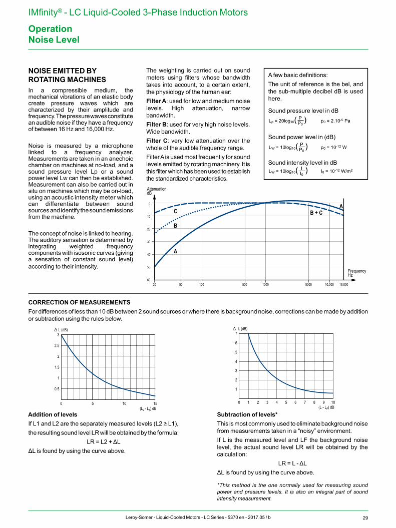
The weighting is carried out on sound meters using filters whose bandwidth takes into account, to a certain extent, the physiology of the human ear:Filter A: used for low and medium noise levels. High attenuation, narrow bandwidth.Filter B: used for very high noise levels. Wide bandwidth.Filter C: very low attenuation over the whole of the audible frequency range.Filter A is used most frequently for sound levels emitted by rotating machinery. It is this filter which has been used to establish the standardized characteristics.
CORRECTION OF MEASUREMENTSFor differences of less than 10 dB between 2 sound sources or where there is background noise, corrections can be made by addition or subtraction using the rules below.
Addition of levelsIf L1 and L2 are the separately measured levels (L2 ≥ L1),the resulting sound level LR will be obtained by the formula:
LR = L2 + ΔLΔL is found by using the curve above.
Subtraction of levels*This is most commonly used to eliminate background noise from measurements taken in a “noisy” environment.If L is the measured level and LF the background noise level, the actual sound level LR will be obtained by the calculation:
LR = L - ΔLΔL is found by using the curve above.
*This method is the one normally used for measuring sound power and pressure levels. It is also an integral part of sound intensity measurement.
0.5
0
1
1.5
2
2.5
3 L (dB)
(L2 - L1) dB155 10 0
7 L (dB)
(L - LF) dB1 2 3 4 5 6 7 8 9 10
1
2
3
4
5
6
FrequencyHz
0
50
C
20
10
20
30
40
50
60100 500 1000 5000 10,000 16,000
B
A
B + CA
AttenuationdB
A few basic definitions:The unit of reference is the bel, and the sub-multiple decibel dB is used here.
Sound pressure level in dB
Sound power level in (dB)
Sound intensity level in dB
PLp = 20log10( ) p0 = 2.10-5 PaP0
PLW = 10log10( ) p0 = 10-12 WP0
LW = 10log10( ) I0 = 10-12 W/m2II0
PLp = 20log10( ) p0 = 2.10-5 PaP0
PLW = 10log10( ) p0 = 10-12 WP0
LW = 10log10( ) I0 = 10-12 W/m2II0
PLp = 20log10( ) p0 = 2.10-5 PaP0
PLW = 10log10( ) p0 = 10-12 WP0
LW = 10log10( ) I0 = 10-12 W/m2II0
30 Leroy-Somer - Liquid-Cooled Motors - LC Series - 5370 en - 2017.05 / b
IMfinity® - LC Liquid-Cooled 3-Phase Induction Motors
OperationWeighted Sound Level [dB(A)]
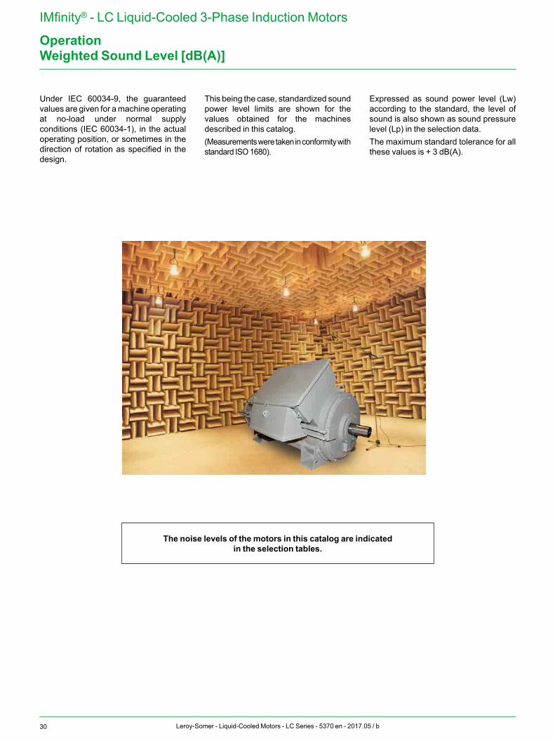
Under IEC 60034-9, the guaranteed values are given for a machine operating at no-load under normal supply conditions (IEC 60034-1), in the actual operating position, or sometimes in the direction of rotation as specified in the design.
This being the case, standardized sound power level limits are shown for the values obtained for the machines described in this catalog.(Measurements were taken in conformity with standard ISO 1680).
Expressed as sound power level (Lw) according to the standard, the level of sound is also shown as sound pressure level (Lp) in the selection data.The maximum standard tolerance for all these values is + 3 dB(A).
The noise levels of the motors in this catalog are indicated in the selection tables.
31Leroy-Somer - Liquid-Cooled Motors - LC Series - 5370 en - 2017.05 / b
IMfinity® - LC Liquid-Cooled 3-Phase Induction Motors
Operation
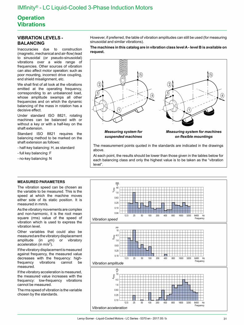
VIBRATION LEVELS - BALANCINGInaccuracies due to construction (magnetic, mechanical and air-flow) lead to sinusoidal (or pseudo-sinusoidal) vibrations over a wide range of frequencies. Other sources of vibration can also affect motor operation: such as poor mounting, incorrect drive coupling, end shield misalignment, etc.We shall first of all look at the vibrations emitted at the operating frequency, corresponding to an unbalanced load, whose amplitude swamps all other frequencies and on which the dynamic balancing of the mass in rotation has a decisive effect.Under standard ISO 8821, rotating machines can be balanced with or without a key or with a half-key on the shaft extension.Standard ISO 8821 requires the balancing method to be marked on the shaft extension as follows:- half-key balancing: H, as standard- full key balancing: F- no-key balancing: N
MEASURED PARAMETERSThe vibration speed can be chosen as the variable to be measured. This is the speed at which the machine moves either side of its static position. It is measured in mm/s.As the vibratory movements are complex and non-harmonic, it is the root mean square (rms) value of the speed of vibration which is used to express the vibration level.Other variables that could also be measured are the vibratory displacement amplitude (in µm) or vibratory acceleration (in m/s2).If the vibratory displacement is measured against frequency, the measured value decreases with the frequency: high-frequency vibrations cannot be measured.If the vibratory acceleration is measured, the measured value increases with the frequency: low-frequency vibrations cannot be measured. The rms speed of vibration is the variable chosen by the standards.
However, if preferred, the table of vibration amplitudes can still be used (for measuring sinusoidal and similar vibrations).The machines in this catalog are in vibration class level A - level B is available on request.
1
4
5
2
3
1
4
5
2
3
Measuring system for suspended machines
Measuring system for machines on flexible mountings
The measurement points quoted in the standards are indicated in the drawings above.At each point, the results should be lower than those given in the tables below for each balancing class and only the highest value is to be taken as the “vibration level”.
0.04
0.10
0.25
0.63
1.6
40
12.5 25 50 100 200 400 800 1600 3200 6400 HzFrequency
V rm
s
mms
Vibration speed
0.10
0.25
0.63
1.6
4.0
10µµ
12.5 25 50 100 200 400 800 1600 3200 6400 HzFrequency
S rm
s
Vibration amplitude
0.10
0.25
0.63
1.6
4.0
10
12.5 25 50 100 200 400 800 1600 3200 6400 HzFrequency
A rm
s
ms2
Vibration acceleration
Vibrations

32 Leroy-Somer - Liquid-Cooled Motors - LC Series - 5370 en - 2017.05 / b
IMfinity® - LC Liquid-Cooled 3-Phase Induction Motors
OperationVibrations
BALANCING THE COUPLINGTo find out the motor balancing type, look at its nameplate.The motors are 1/2 key balancing as standard, unless otherwise indicated. The coupling balancing must be adapted to the motor balancing and the coupling adapted to the key length or any visible parts overhanging the key must be machined.An adapted key can be used.
Important: Failure to comply with these recommendations can lead to premature wear of the bearings and can invalidate the manufacturer warranty.
MAXIMUM VIBRATION MAGNITUDE LIMITS (RMS VALUES) IN TERMS OF DISPLACEMENT, SPEED AND ACCELERATION FOR A FRAME SIZE H (IEC 60034-14)
Level ofvibration
H > 280
Displacementµm
Speedmm/s
Accelerationm/s2
A 45 2.8 4.4
B 29 1.8 2.8
For large machines and special requirements with regard to vibration, balancing can be carried out in situ (finished assembly).Prior consultation is essential, as the machine dimensions may be modified by the necessary addition of balancing disks mounted on the shaft extensions.
Coupling adapted to the key length
Machining of visible parts overhanging the key
COMPLIANT MOUNTINGS
NON-COMPLIANT MOUNTING
Non-machined overhanging key
Coupling not adapted to the key length
Part to be machined
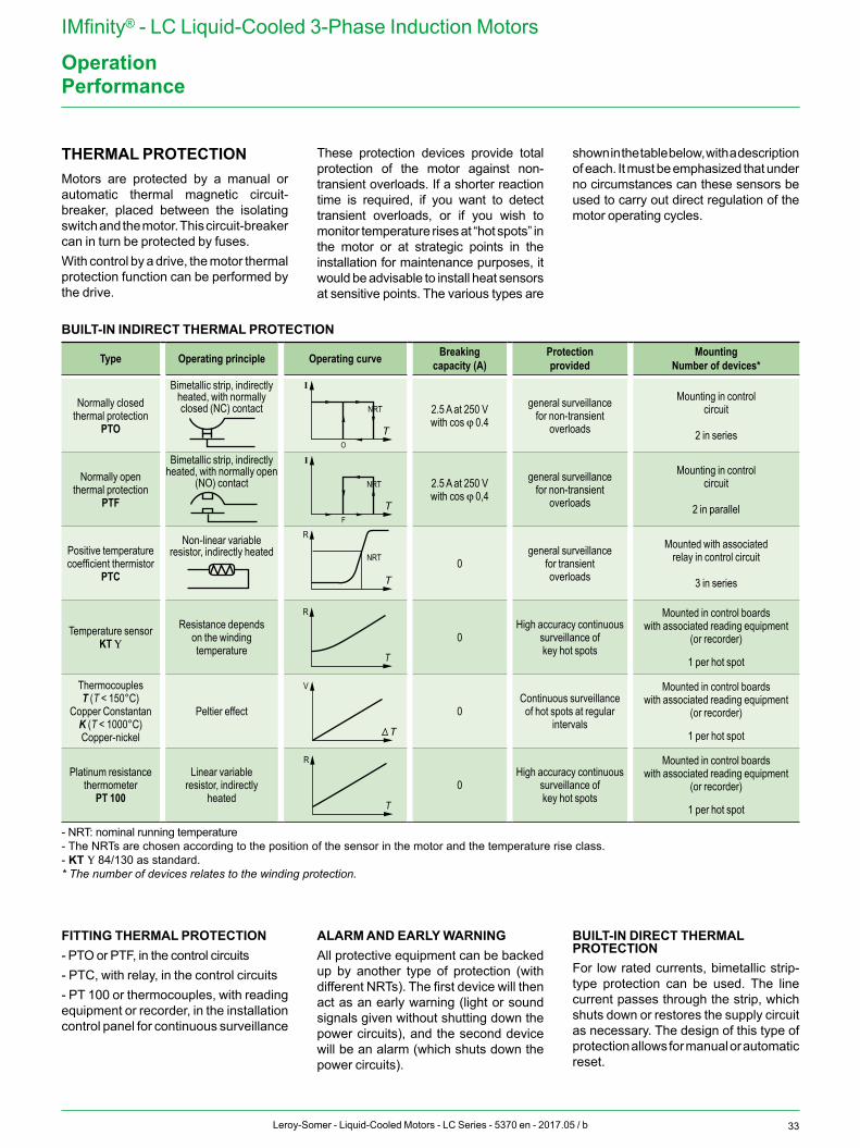
33Leroy-Somer - Liquid-Cooled Motors - LC Series - 5370 en - 2017.05 / b
IMfinity® - LC Liquid-Cooled 3-Phase Induction Motors
Operation
BUILT-IN INDIRECT THERMAL PROTECTION
Type Operating principle Operating curve Breaking capacity (A)
Protection provided
MountingNumber of devices*
Normally closed thermal protection
PTO
Bimetallic strip, indirectly heated, with normally closed (NC) contact
I
OT
2.5 A at 250 Vwith cos j 0.4
general surveillancefor non-transient
overloads
Mounting in control circuit
2 in series
Normally open thermal protection
PTF
Bimetallic strip, indirectly heated, with normally open
(NO) contact
I
FT
2.5 A at 250 Vwith cos j 0,4
general surveillancefor non-transient
overloads
Mounting in control circuit
2 in parallel
Positive temperature coefficient thermistor
PTC
Non-linear variable resistor, indirectly heated
R
T0
general surveillancefor transient overloads
Mounted with associated relay in control circuit
3 in series
Temperature sensorKT U
Resistance depends on the winding temperature
R
T
0High accuracy continuous
surveillance of key hot spots
Mounted in control boards with associated reading equipment
(or recorder)
1 per hot spot
ThermocouplesT (T < 150°C)
Copper ConstantanK (T < 1000°C)Copper-nickel
Peltier effect
V
T
0Continuous surveillance of hot spots at regular
intervals
Mounted in control boards with associated reading equipment
(or recorder)
1 per hot spot
Platinum resistance thermometer
PT 100
Linear variable resistor, indirectly
heated
R
T
0High accuracy continuous
surveillance of key hot spots
Mounted in control boards with associated reading equipment
(or recorder)
1 per hot spot
- NRT: nominal running temperature- The NRTs are chosen according to the position of the sensor in the motor and the temperature rise class.- KT U 84/130 as standard.* The number of devices relates to the winding protection.
THERMAL PROTECTIONMotors are protected by a manual or automatic thermal magnetic circuit-breaker, placed between the isolating switch and the motor. This circuit-breaker can in turn be protected by fuses.With control by a drive, the motor thermal protection function can be performed by the drive.
These protection devices provide total protection of the motor against non-transient overloads. If a shorter reaction time is required, if you want to detect transient overloads, or if you wish to monitor temperature rises at “hot spots” in the motor or at strategic points in the installation for maintenance purposes, it would be advisable to install heat sensors at sensitive points. The various types are
shown in the table below, with a description of each. It must be emphasized that under no circumstances can these sensors be used to carry out direct regulation of the motor operating cycles.
FITTING THERMAL PROTECTION- PTO or PTF, in the control circuits- PTC, with relay, in the control circuits- PT 100 or thermocouples, with reading equipment or recorder, in the installation control panel for continuous surveillance
ALARM AND EARLY WARNINGAll protective equipment can be backed up by another type of protection (with different NRTs). The first device will then act as an early warning (light or sound signals given without shutting down the power circuits), and the second device will be an alarm (which shuts down the power circuits).
BUILT-IN DIRECT THERMAL PROTECTIONFor low rated currents, bimetallic strip-type protection can be used. The line current passes through the strip, which shuts down or restores the supply circuit as necessary. The design of this type of protection allows for manual or automatic reset.
Performance
NRT
NRT
NRT
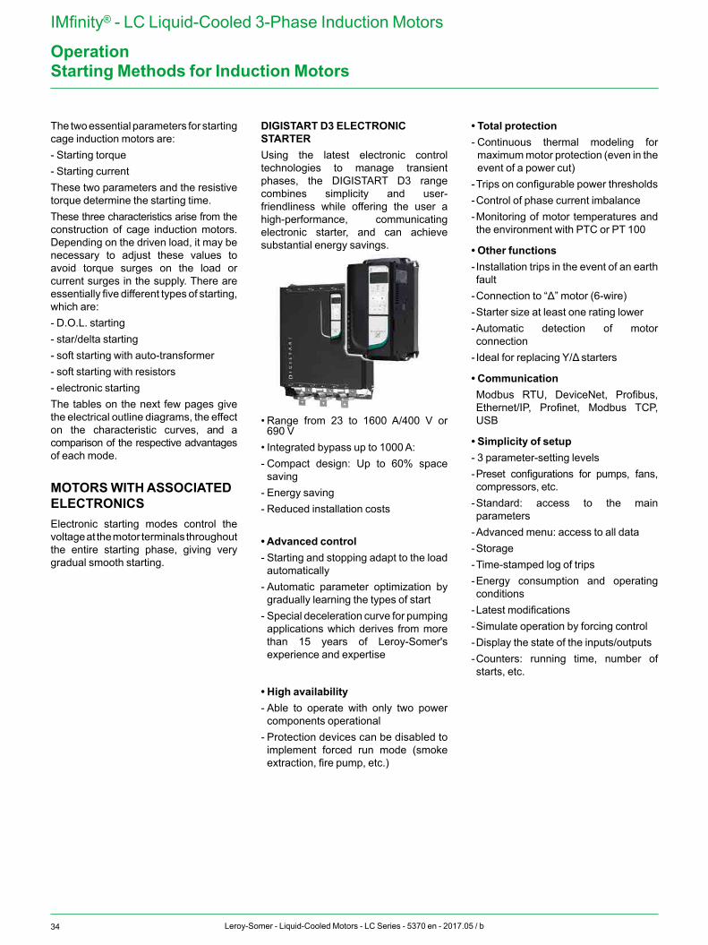
34 Leroy-Somer - Liquid-Cooled Motors - LC Series - 5370 en - 2017.05 / b
IMfinity® - LC Liquid-Cooled 3-Phase Induction Motors
OperationStarting Methods for Induction Motors
The two essential parameters for starting cage induction motors are:- Starting torque- Starting currentThese two parameters and the resistive torque determine the starting time.These three characteristics arise from the construction of cage induction motors. Depending on the driven load, it may be necessary to adjust these values to avoid torque surges on the load or current surges in the supply. There are essentially five different types of starting, which are:- D.O.L. starting- star/delta starting- soft starting with auto-transformer- soft starting with resistors- electronic startingThe tables on the next few pages give the electrical outline diagrams, the effect on the characteristic curves, and a comparison of the respective advantages of each mode.
MOTORS WITH ASSOCIATED ELECTRONICSElectronic starting modes control the voltage at the motor terminals throughout the entire starting phase, giving very gradual smooth starting.
DIGISTART D3 ELECTRONIC STARTERUsing the latest electronic control technologies to manage transient phases, the DIGISTART D3 range combines simplicity and user-friendliness while offering the user a high-performance, communicating electronic starter, and can achieve substantial energy savings.
• Range from 23 to 1600 A/400 V or 690 V
• Integrated bypass up to 1000 A:- Compact design: Up to 60% space saving
- Energy saving- Reduced installation costs
• Advanced control- Starting and stopping adapt to the load automatically
- Automatic parameter optimization by gradually learning the types of start
- Special deceleration curve for pumping applications which derives from more than 15 years of Leroy-Somer's experience and expertise
• High availability- Able to operate with only two power components operational
- Protection devices can be disabled to implement forced run mode (smoke extraction, fire pump, etc.)
• Total protection- Continuous thermal modeling for maximum motor protection (even in the event of a power cut)
- Trips on configurable power thresholds- Control of phase current imbalance- Monitoring of motor temperatures and the environment with PTC or PT 100
• Other functions- Installation trips in the event of an earth fault
- Connection to “Δ” motor (6-wire)- Starter size at least one rating lower- Automatic detection of motor connection
- Ideal for replacing Y/Δ starters
• Communication Modbus RTU, DeviceNet, Profibus, Ethernet/IP, Profinet, Modbus TCP, USB
• Simplicity of setup- 3 parameter-setting levels- Preset configurations for pumps, fans, compressors, etc.
- Standard: access to the main parameters
- Advanced menu: access to all data- Storage- Time-stamped log of trips- Energy consumption and operating conditions
- Latest modifications- Simulate operation by forcing control- Display the state of the inputs/outputs- Counters: running time, number of starts, etc.
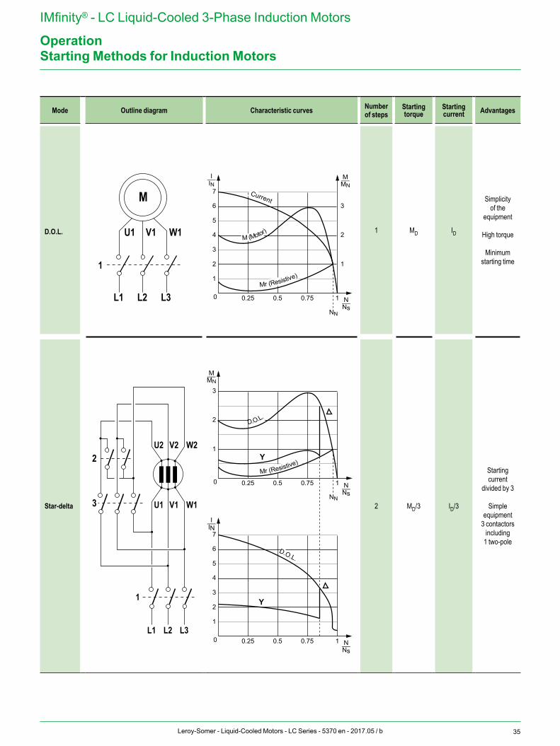
35Leroy-Somer - Liquid-Cooled Motors - LC Series - 5370 en - 2017.05 / b
IMfinity® - LC Liquid-Cooled 3-Phase Induction Motors
OperationStarting Methods for Induction Motors
Mode Outline diagram Characteristic curves Number of steps
Starting torque
Starting current Advantages
D.O.L. 1 MD ID
Simplicity of the
equipment
High torque
Minimum starting time
Star-delta 2 MD/3 ID/3
Starting current
divided by 3
Simple equipment
3 contactors including
1 two-pole
L3L2L1
W1V1U1
M
1
L3L2L1
W1V1U1
1
3
W2V2U2
0.25 0.5 0.75 1
1
2
3
2
4
6
1
3
5
7
0
M (Motor)
Current
Mr (Resistive)
0.25 0.5 0.75 1
1
2
3
0
D.O.L.
Mr (Resistive) Y
0.25 0.5 0.75 1
2
4
6
1
3
5
7
0
Y
D.O.L.
2
M_MN
N_Ns
I_IN
M_MN
N_Ns
N_Ns
I_IN
NN
NN
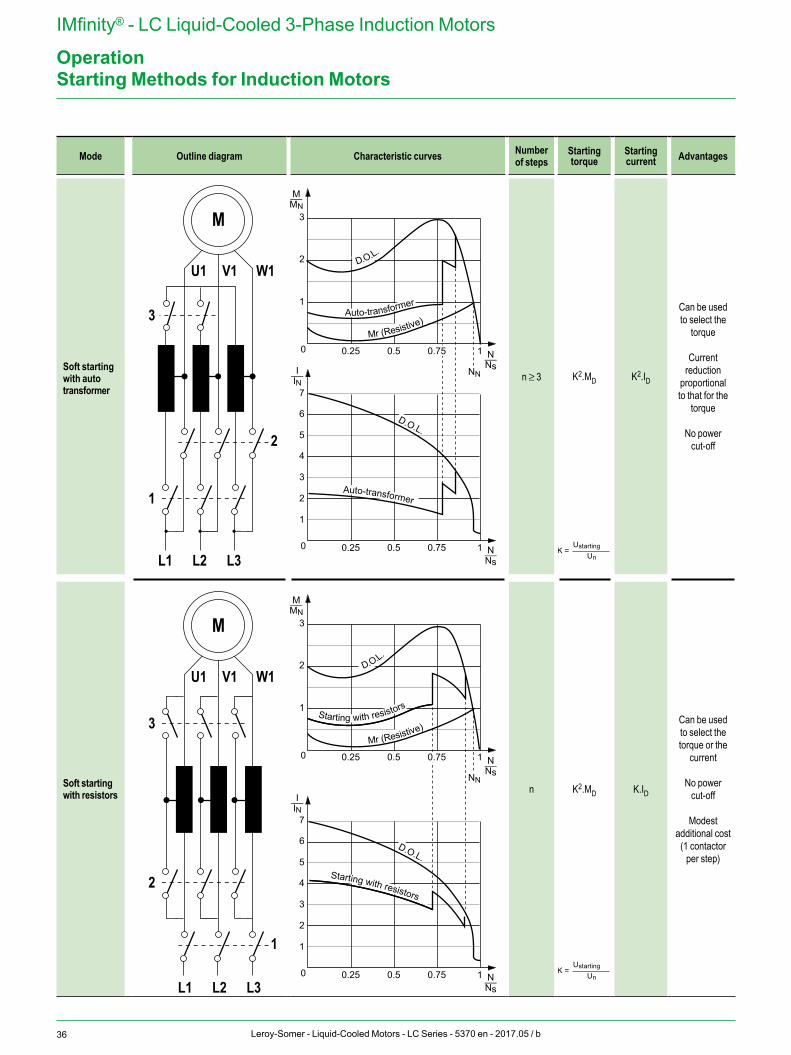
36 Leroy-Somer - Liquid-Cooled Motors - LC Series - 5370 en - 2017.05 / b
IMfinity® - LC Liquid-Cooled 3-Phase Induction Motors
OperationStarting Methods for Induction Motors
Mode Outline diagram Characteristic curves Number of steps
Starting torque
Starting current Advantages
Soft starting with auto transformer
n ≥ 3 K2.MD K2.ID
Can be used to select the
torque
Current reduction
proportional to that for the
torque
No power cut-off
Soft starting with resistors n K2.MD K.ID
Can be used to select the torque or the
current
No power cut-off
Modest additional cost
(1 contactor per step)
K =Ustarting
Un
K =Ustarting
Un
W1V1U1
M
2
L3L2L1
1
3
W1V1U1
1
L3L2L1
2
3
M
0.25 0.5 1
1
2
3
0
D.O.L.
Mr (Resistive)
0.25 0.5 0.75 1
2
4
6
1
3
5
7
0
Auto-transformer
Auto-transformer
D.O.L.
0.25 0.5 1
1
2
3
0Mr (Resistive)
0.25 0.5 0.75 1
2
4
6
1
3
5
7
0
D.O.L.
Starting with resistors
D.O.L.
Starting with resistors
0.75
0.75
M_MN
N_Ns
N_Ns
I_IN
M_MN
N_Ns
N_Ns
I_IN
NN
NN
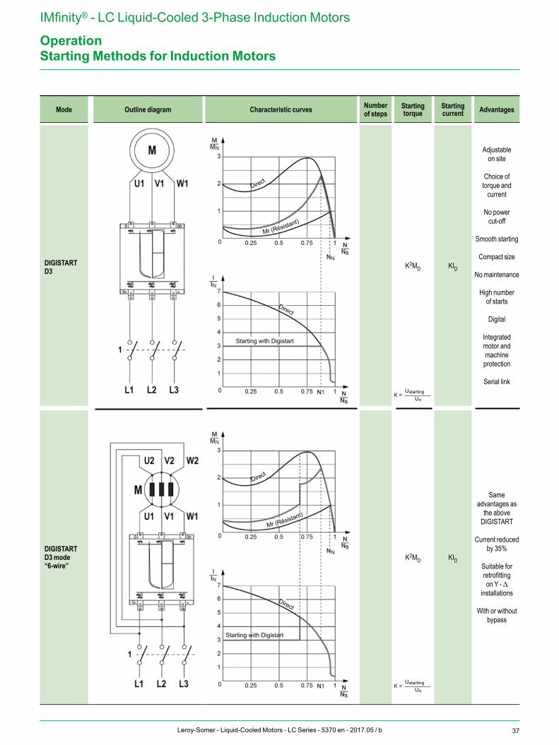
37Leroy-Somer - Liquid-Cooled Motors - LC Series - 5370 en - 2017.05 / b
IMfinity® - LC Liquid-Cooled 3-Phase Induction Motors
Operation
Mode Outline diagram Characteristic curves Number of steps
Starting torque
Starting current Advantages
DIGISTARTD3
K2MD KID
Adjustable on site
Choice of torque and
current
No power cut-off
Smooth starting
Compact size
No maintenance
High number of starts
Digital
Integrated motor and machine
protection
Serial link
DIGISTARTD3 mode“6-wire”
K2MD KID
Same advantages as
the above DIGISTART
Current reduced by 35%
Suitable for retrofitting on Y - Δ
installations
With or without bypass
Starting Methods for Induction Motors
K =Ustarting
Un
K =Ustarting
Un
Direct
Direct
Mr (Résistant)
Mr (Résistant)
Direct
Direct
Starting with Digistart
Starting with Digistart
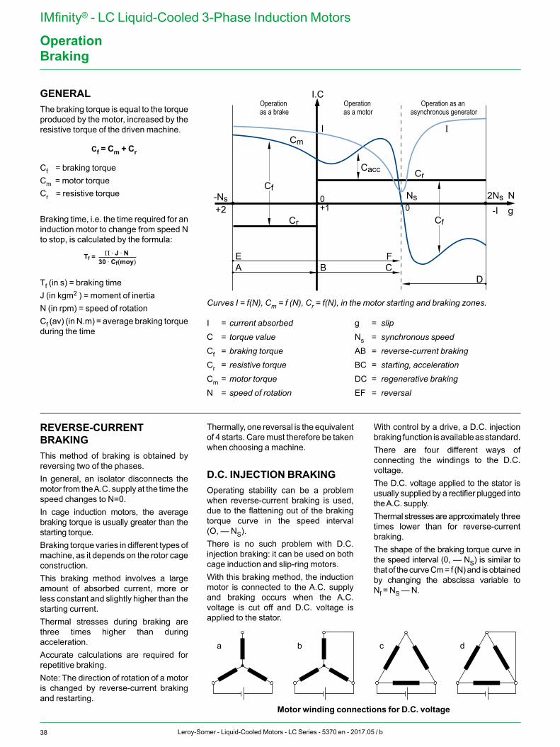
38 Leroy-Somer - Liquid-Cooled Motors - LC Series - 5370 en - 2017.05 / b
IMfinity® - LC Liquid-Cooled 3-Phase Induction Motors
OperationBraking
Curves I = f(N), Cm = f (N), Cr = f(N), in the motor starting and braking zones.
I = current absorbed g = slipC = torque value Ns = synchronous speedCf = braking torque AB = reverse-current brakingCr = resistive torque BC = starting, accelerationCm = motor torque DC = regenerative brakingN = speed of rotation EF = reversal
GENERALThe braking torque is equal to the torque produced by the motor, increased by the resistive torque of the driven machine.
Cf = Cm + Cr
Cf = braking torqueCm = motor torqueCr = resistive torque
Braking time, i.e. the time required for an induction motor to change from speed N to stop, is calculated by the formula:
Π . J . NTf =
If = k1i x Id√
30 . Cf(moy)
Π . J . NCf = 30 . Tf
1
Cf - Cfek2 - Cd
√3
Tf (in s) = braking timeJ (in kgm2 ) = moment of inertiaN (in rpm) = speed of rotationCf (av) (in N.m) = average braking torque during the time
REVERSE-CURRENT BRAKINGThis method of braking is obtained by rever sing two of the phases.In general, an isolator disconnects the motor from the A.C. supply at the time the speed changes to N=0.In cage induction motors, the average braking torque is usually greater than the starting torque.Braking torque varies in different types of machine, as it depends on the rotor cage construction.This braking method involves a large amount of absorbed current, more or less constant and slightly higher than the starting current.Thermal stresses during braking are three times higher than during acceleration.Accurate calculations are required for repetitive braking.Note: The direction of rotation of a motor is changed by reverse-current braking and restarting.
Thermally, one reversal is the equivalent of 4 starts. Care must therefore be taken when choosing a machine.
D.C. INJECTION BRAKINGOperating stability can be a problem when reverse-current braking is used, due to the flattening out of the braking torque curve in the speed interval (O, — NS).There is no such problem with D.C. injection braking: it can be used on both cage induction and slip-ring motors.With this braking method, the induction motor is connected to the A.C. supply and braking occurs when the A.C. voltage is cut off and D.C. voltage is applied to the stator.
With control by a drive, a D.C. injection braking function is available as standard.There are four different ways of connecting the windings to the D.C. voltage.The D.C. voltage applied to the stator is usually supplied by a rectifier plugged into the A.C. supply.Thermal stresses are approximately three times lower than for reverse-current braking.The shape of the braking torque curve in the speed interval (0, — NS) is similar to that of the curve Cm = f (N) and is obtained by changing the abscissa variable to Nf = NS — N.
a b c d
Motor winding connections for D.C. voltage
-Ns+2
2NsNs
-IN g
I.C
Cm
Cr
Cf
EA B C
F
D
Cr
0+1 0
Cf
I
Operation as a brake
Operation as a motor
Operation as an asynchronous generator
Cacc
I
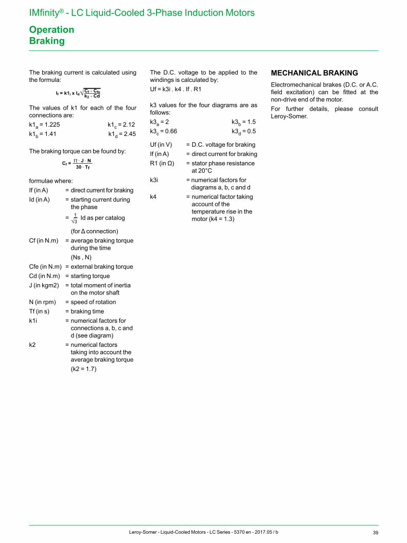
39Leroy-Somer - Liquid-Cooled Motors - LC Series - 5370 en - 2017.05 / b
IMfinity® - LC Liquid-Cooled 3-Phase Induction Motors
OperationBraking
The braking current is calculated using the for mula:
Π . J . NTf =
If = k1i x Id√
30 . Cf(moy)
Π . J . NCf = 30 . Tf
1
Cf - Cfek2 - Cd
√3
The values of k1 for each of the four connections are:k1a = 1.225 k1c = 2.12k1b = 1.41 k1d = 2.45
The braking torque can be found by:
Π . J . NTf =
If = k1i x Id√
30 . Cf(moy)
Π . J . NCf = 30 . Tf
1
Cf - Cfek2 - Cd
√3
formulae where:If (in A) = direct current for brakingId (in A) = starting current during
the phase
=
Π . J . NTf =
If = k1i x Id√
30 . Cf(moy)
Π . J . NCf = 30 . Tf
1
Cf - Cfek2 - Cd
√3 Id as per catalog
(for Δ connection)Cf (in N.m) = average braking torque
during the time (Ns , N)Cfe (in N.m) = external braking torqueCd (in N.m) = starting torqueJ (in kgm2) = total moment of inertia
on the motor shaftN (in rpm) = speed of rotationTf (in s) = braking timek1i = numerical factors for
connections a, b, c and d (see diagram)
k2 = numerical factors taking into account the average braking torque
(k2 = 1.7)
The D.C. voltage to be applied to the windings is calculated by:Uf = k3i . k4 . If . R1
k3 values for the four diagrams are as follows:k3a = 2 k3b = 1.5k3c = 0.66 k3d = 0.5
Uf (in V) = D.C. voltage for brakingIf (in A) = direct current for brakingR1 (in Ω) = stator phase resistance
at 20°Ck3i = numerical factors for
diagrams a, b, c and dk4 = numerical factor taking
account of the temperature rise in the motor (k4 = 1.3)
MECHANICAL BRAKINGElectromechanical brakes (D.C. or A.C. field excitation) can be fitted at the non-drive end of the motor.For further details, please consult Leroy-Somer.
40 Leroy-Somer - Liquid-Cooled Motors - LC Series - 5370 en - 2017.05 / b
IMfinity® - LC Liquid-Cooled 3-Phase Induction Motors
OperationUse with Variable Speed Drive
MOTORS USED WITH VARIABLE SPEED DRIVE
GENERALDrive control by a frequency inverter can in fact result in an increase in the machine temperature rise, due to a significantly lower supply voltage than on the A.C. supply, additional losses related to the wave form produced by the drive (PWM).Standard IEC 60034-17 describes numerous good practices for all types of electric motor, however since this is Leroy-Somer's area of specialist expertise, we describe the best ways to deal with variable speed in the section below.LC motors are particularly suitable for use at constant torque across the entire speed range from 0 to 50 Hz, without derating. The motor cooling capacity remains constant whatever the point of operation.These motors are quieter when operating at overspeed (above the motor rated speed).
DERATING THE POWER WHEN THE LC RANGE IS USED AT VARIABLE SPEEDThe thermal reserve, a Leroy-Somer special feature, should be used to keep the motor in its temperature class. However in certain cases, the temperature class will change from B to F, i.e. between 80 k and 105 k.
ADAPTATION OF MOTORSA motor is always characterized by the following parameters, which depend on the design:- temperature class- voltage range- frequency range- thermal reserve
CHANGES IN MOTOR PERFORMANCEWhen power is supplied by a drive, changes are observed in the above parameters due to certain phenomena:- voltage drops in the drive components- current increase in proportion with the decrease in voltage - difference in motor power supply according to the type of control (flux vector or U/F) The main consequence is an increase in the motor current resulting in increased copper losses and therefore a higher temperature rise in the winding (even at 50 Hz).Above the synchronous speed, the iron losses increase and hence cause further temperature rise in the motor.The type of control mode influences temperature rise in the motor:- A U/F ratio gives the fundamental voltage maximum at 50 Hz but requires more current at low speed to obtain a high starting torque and therefore generates a temperature rise at low speed when the motor is poorly ventilated.- Flux vector control requires less current at low speed while providing significant torque but regulates the voltage at 50 Hz and causes a voltage drop at the motor terminals, therefore requiring more current at the same power.
Consequences on the motorReminder: Leroy-Somer recommends the connection of PTC sensors, monitored by the drive, to protect the motor as much as possible.
CONSEQUENCES OF POWER SUPPLIED BY DRIVESWhen power is supplied to the motor by a variable speed drive with diode rectifier, this causes a voltage drop (~5%).Some PWM techniques can be used to limit this voltage drop (~2%), to the detriment of the machine temperature rise (injection of harmonics of orders 5 and 7).The non-sinusoidal signal (PWM) provided by the drive generates voltage peaks at the winding terminals due to the significant voltage variations related to switching of the IGBTs (also called dV/dt). Repeated overvoltages can eventually damage the windings depending on their value and/or the motor design.
The value of the voltage peaks is proportional to the supply voltage. This value can exceed the minimum voltage for the windings which is related to the wire grade, the impregnation type and the insulation that may or may not be present in the slot bottoms or between phases.Another option for attaining high voltage values is when regeneration phenomena occur in the case of a driving load, hence the need to prioritize freewheel stops or following the longest permissible ramp.
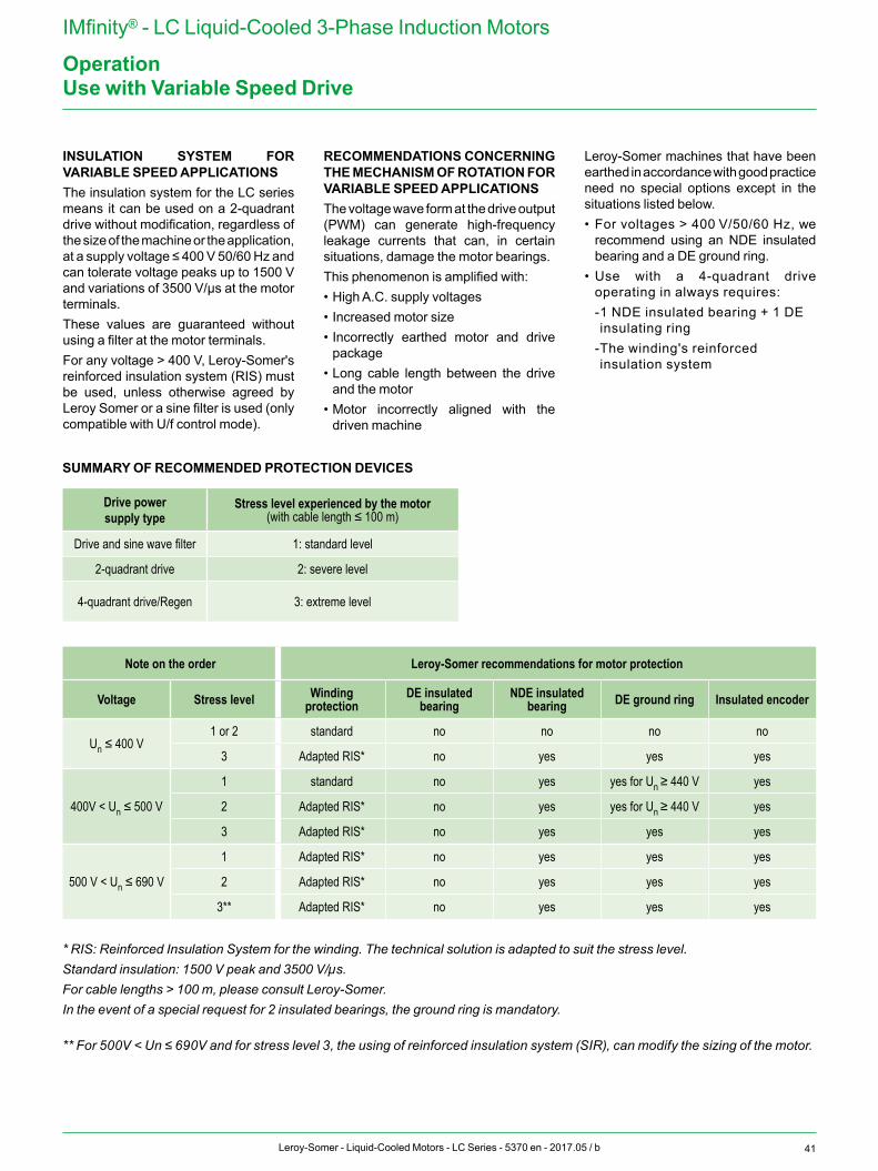
41Leroy-Somer - Liquid-Cooled Motors - LC Series - 5370 en - 2017.05 / b
IMfinity® - LC Liquid-Cooled 3-Phase Induction Motors
OperationUse with Variable Speed Drive
* RIS: Reinforced Insulation System for the winding. The technical solution is adapted to suit the stress level.Standard insulation: 1500 V peak and 3500 V/µs.For cable lengths > 100 m, please consult Leroy-Somer.In the event of a special request for 2 insulated bearings, the ground ring is mandatory.
** For 500V < Un ≤ 690V and for stress level 3, the using of reinforced insulation system (SIR), can modify the sizing of the motor.
SUMMARY OF RECOMMENDED PROTECTION DEVICES
INSULATION SYSTEM FOR VARIABLE SPEED APPLICATIONSThe insulation system for the LC series means it can be used on a 2-quadrant drive without modification, regardless of the size of the machine or the application, at a supply voltage ≤ 400 V 50/60 Hz and can tolerate voltage peaks up to 1500 V and variations of 3500 V/µs at the motor terminals.These values are guaranteed without using a filter at the motor terminals.For any voltage > 400 V, Leroy-Somer's reinforced insulation system (RIS) must be used, unless otherwise agreed by Leroy Somer or a sine filter is used (only compatible with U/f control mode).
RECOMMENDATIONS CONCERNING THE MECHANISM OF ROTATION FOR VARIABLE SPEED APPLICATIONSThe voltage wave form at the drive output (PWM) can generate high-frequency leakage currents that can, in certain situations, damage the motor bearings.This phenomenon is amplified with:• High A.C. supply voltages• Increased motor size• Incorrectly earthed motor and drive
package• Long cable length between the drive
and the motor• Motor incorrectly aligned with the
driven machine
Leroy-Somer machines that have been earthed in accordance with good practice need no special options except in the situations listed below.• For voltages > 400 V/50/60 Hz, we
recommend using an NDE insulated bearing and a DE ground ring.
• Use with a 4-quadrant drive operating in always requires:
- 1 NDE insulated bearing + 1 DE insulating ring
- The winding's reinforced insulation system
Drive power supply type
Stress level experienced by the motor(with cable length ≤ 100 m)
Drive and sine wave filter 1: standard level
2-quadrant drive 2: severe level
4-quadrant drive/Regen 3: extreme level
Note on the order Leroy-Somer recommendations for motor protection
Voltage Stress level Winding protection
DE insulated bearing
NDE insulated bearing DE ground ring Insulated encoder
Un ≤ 400 V1 or 2 standard no no no no
3 Adapted RIS* no yes yes yes
400V < Un ≤ 500 V
1 standard no yes yes for Un ≥ 440 V yes
2 Adapted RIS* no yes yes for Un ≥ 440 V yes
3 Adapted RIS* no yes yes yes
500 V < Un ≤ 690 V
1 Adapted RIS* no yes yes yes
2 Adapted RIS* no yes yes yes
3** Adapted RIS* no yes yes yes
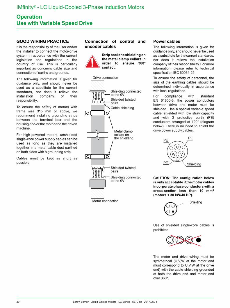
42 Leroy-Somer - Liquid-Cooled Motors - LC Series - 5370 en - 2017.05 / b
IMfinity® - LC Liquid-Cooled 3-Phase Induction Motors
OperationUse with Variable Speed Drive
GOOD WIRING PRACTICEIt is the responsibility of the user and/or the installer to connect the motor-drive system in accordance with the current legislation and regulations in the country of use. This is particularly important as concerns cable size and connection of earths and grounds.
The following information is given for guidance only, and should never be used as a substitute for the current standards, nor does it relieve the installation company of their responsibility.
To ensure the safety of motors with frame size 315 mm or above, we recommend installing grounding strips between the terminal box and the housing and/or the motor and the driven machine.
For high-powered motors, unshielded single-core power supply cables can be used as long as they are installed together in a metal cable duct earthed on both sides with a grounding strip.
Cables must be kept as short as possible.
Connection of control and encoder cables
Strip back the shielding on the metal clamp collars in order to ensure 360° contact.
Metal clamp collars on the shielding
Shielding connected to the 0V
Shielding connected to the 0V
Shielded twisted pairs
Shielded twisted pairs
Cable shielding
Drive connection
Motor connection
Power cablesThe following information is given for guidance only, and should never be used as a substitute for the current standards, nor does it relieve the installation company of their responsibility. For more information, please refer to technical specification IEC 60034-25. To ensure the safety of personnel, the size of the earthing cables should be determined individually in accordance with local regulations.For compliance with standard EN 61800-3, the power conductors between drive and motor must be shielded. Use a special variable speed cable: shielded with low stray capacity and with 3 protective earth (PE) conductors arranged at 120° (diagram below). There is no need to shield the drive power supply cables.
U
V
Shielding
PEPE
PE
W
CAUTION: The configuration below is only acceptable if the motor cables incorporate phase conductors with a cross-section less than 10 mm2 (motors < 30 kW/40 HP).
Shielding
Use of shielded single-core cables is prohibited.
The motor and drive wiring must be symmetrical (U,V,W at the motor end must correspond to U,V,W at the drive end) with the cable shielding grounded at both the drive end and motor end over 360°.
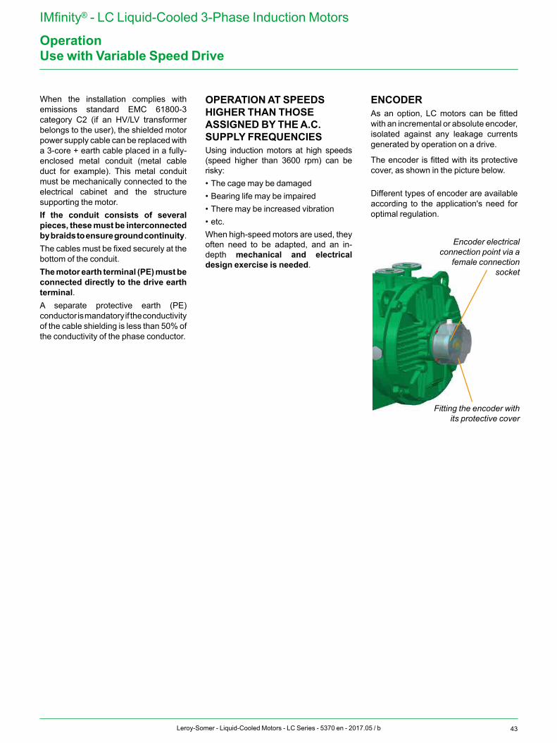
43Leroy-Somer - Liquid-Cooled Motors - LC Series - 5370 en - 2017.05 / b
IMfinity® - LC Liquid-Cooled 3-Phase Induction Motors
Operation
When the installation complies with emissions standard EMC 61800-3 category C2 (if an HV/LV transformer belongs to the user), the shielded motor power supply cable can be replaced with a 3-core + earth cable placed in a fully-enclosed metal conduit (metal cable duct for example). This metal conduit must be mechanically connected to the electrical cabinet and the structure supporting the motor.If the conduit consists of several pieces, these must be interconnected by braids to ensure ground continuity. The cables must be fixed securely at the bottom of the conduit.The motor earth terminal (PE) must be connected directly to the drive earth terminal.A separate protective earth (PE) conductor is mandatory if the conductivity of the cable shielding is less than 50% of the conductivity of the phase conductor.
OPERATION AT SPEEDS HIGHER THAN THOSE ASSIGNED BY THE A.C. SUPPLY FREQUENCIESUsing induction motors at high speeds (speed higher than 3600 rpm) can be risky:• The cage may be damaged • Bearing life may be impaired • There may be increased vibration • etc.When high-speed motors are used, they often need to be adapted, and an in-depth mechanical and electrical design exercise is needed.
ENCODER As an option, LC motors can be fitted with an incremental or absolute encoder, isolated against any leakage currents generated by operation on a drive.
The encoder is fitted with its protective cover, as shown in the picture below.
Different types of encoder are available according to the application's need for optimal regulation.
Use with Variable Speed Drive
Encoder electrical connection point via a
female connection socket
Fitting the encoder with its protective cover
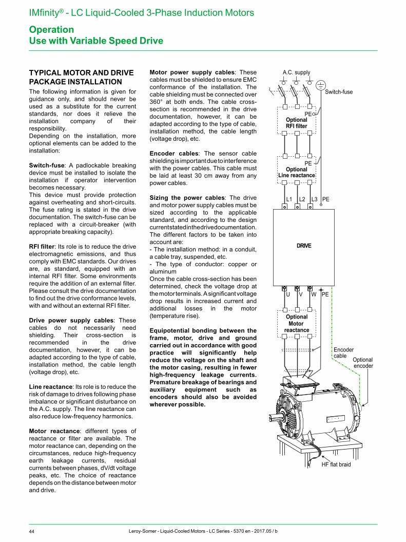
44 Leroy-Somer - Liquid-Cooled Motors - LC Series - 5370 en - 2017.05 / b
IMfinity® - LC Liquid-Cooled 3-Phase Induction Motors
OperationUse with Variable Speed Drive
TYPICAL MOTOR AND DRIVE PACKAGE INSTALLATIONThe following information is given for guidance only, and should never be used as a substitute for the current standards, nor does it relieve the installation company of their responsibility.Depending on the installation, more optional elements can be added to the installation:
Switch-fuse: A padlockable breaking device must be installed to isolate the installation if operator intervention becomes necessary.This device must provide protection against overheating and short-circuits. The fuse rating is stated in the drive documentation. The switch-fuse can be replaced with a circuit-breaker (with appropriate breaking capacity).
RFI filter: Its role is to reduce the drive electromagnetic emissions, and thus comply with EMC standards. Our drives are, as standard, equipped with an internal RFI filter. Some environments require the addition of an external filter. Please consult the drive documentation to find out the drive conformance levels, with and without an external RFI filter.
Drive power supply cables: These cables do not necessarily need shielding. Their cross-section is recommended in the drive documentation, however, it can be adapted according to the type of cable, installation method, the cable length (voltage drop), etc.
Line reactance: Its role is to reduce the risk of damage to drives following phase imbalance or significant disturbance on the A.C. supply. The line reactance can also reduce low-frequency harmonics.
Motor reactance: different types of reactance or filter are available. The motor reactance can, depending on the circumstances, reduce high-frequency earth leakage currents, residual currents between phases, dV/dt voltage peaks, etc. The choice of reactance depends on the distance between motor and drive.
Motor power supply cables: These cables must be shielded to ensure EMC conformance of the installation. The cable shielding must be connected over 360° at both ends. The cable cross-section is recommended in the drive documentation, however, it can be adapted according to the type of cable, installation method, the cable length (voltage drop), etc.
Encoder cables: The sensor cable shielding is important due to interference with the power cables. This cable must be laid at least 30 cm away from any power cables.
Sizing the power cables: The drive and motor power supply cables must be sized according to the applicable standard, and according to the design current stated in the drive documentation.The different factors to be taken into account are:- The installation method: in a conduit, a cable tray, suspended, etc.- The type of conductor: copper or aluminumOnce the cable cross-section has been determined, check the voltage drop at the motor terminals. A significant voltage drop results in increased current and additional losses in the motor (temperature rise).
Equipotential bonding between the frame, motor, drive and ground carried out in accordance with good practice will significantly help reduce the voltage on the shaft and the motor casing, resulting in fewer high-frequency leakage currents. Premature breakage of bearings and auxiliary equipment such as encoders should also be avoided wherever possible.
L1 L2 L3 PE
U V W PE
PE
PE
DRIVE
OptionalRFI filter
A.C. supply
Switch-fuse
OptionalLine reactance
Optional encoder
Encoder cable
HF flat braid
OptionalMotor
reactance
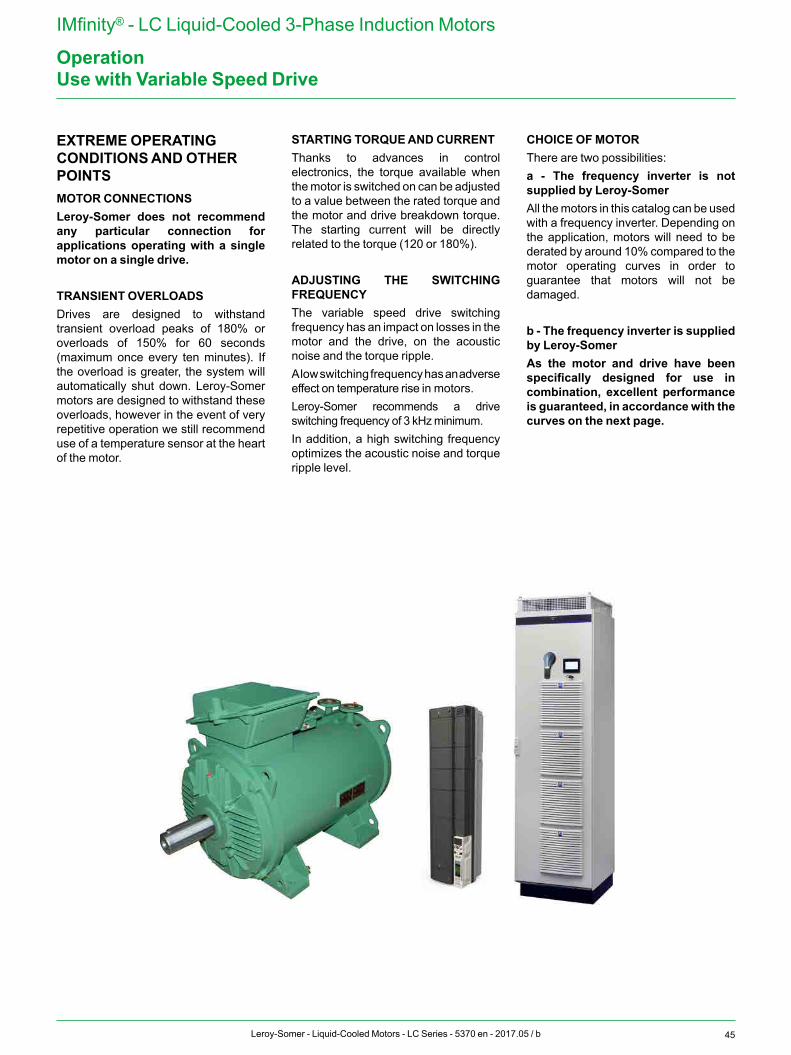
45Leroy-Somer - Liquid-Cooled Motors - LC Series - 5370 en - 2017.05 / b
IMfinity® - LC Liquid-Cooled 3-Phase Induction Motors
Operation
EXTREME OPERATING CONDITIONS AND OTHER POINTSMOTOR CONNECTIONSLeroy-Somer does not recommend any particular connection for applications operating with a single motor on a single drive.
TRANSIENT OVERLOADSDrives are designed to withstand transient overload peaks of 180% or overloads of 150% for 60 seconds (maximum once every ten minutes). If the overload is greater, the system will automatically shut down. Leroy-Somer motors are designed to withstand these overloads, however in the event of very repetitive operation we still recommend use of a temperature sensor at the heart of the motor.
STARTING TORQUE AND CURRENTThanks to advances in control electronics, the torque available when the motor is switched on can be adjusted to a value between the rated torque and the motor and drive breakdown torque. The starting current will be directly related to the torque (120 or 180%).
ADJUSTING THE SWITCHING FREQUENCYThe variable speed drive switching frequency has an impact on losses in the motor and the drive, on the acoustic noise and the torque ripple.A low switching frequency has an adverse effect on temperature rise in motors.Leroy-Somer recommends a drive switching frequency of 3 kHz minimum. In addition, a high switching frequency optimizes the acoustic noise and torque ripple level.
CHOICE OF MOTORThere are two possibilities:a - The frequency inverter is not supplied by Leroy-SomerAll the motors in this catalog can be used with a frequency inverter. Depending on the application, motors will need to be derated by around 10% compared to the motor operating curves in order to guarantee that motors will not be damaged.
b - The frequency inverter is supplied by Leroy-SomerAs the motor and drive have been specifically designed for use in combination, excellent performance is guaranteed, in accordance with the curves on the next page.
Use with Variable Speed Drive
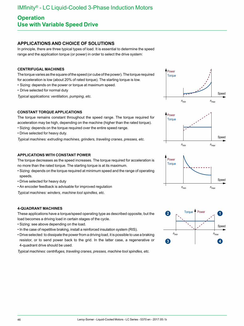
46 Leroy-Somer - Liquid-Cooled Motors - LC Series - 5370 en - 2017.05 / b
IMfinity® - LC Liquid-Cooled 3-Phase Induction Motors
Operation
APPLICATIONS AND CHOICE OF SOLUTIONSIn principle, there are three typical types of load. It is essential to determine the speed range and the application torque (or power) in order to select the drive system:
CENTRIFUGAL MACHINESThe torque varies as the square of the speed (or cube of the power). The torque required for acceleration is low (about 20% of rated torque). The starting torque is low.• Sizing: depends on the power or torque at maximum speed.• Drive selected for normal dutyTypical applications: ventilation, pumping, etc.
CONSTANT TORQUE APPLICATIONSThe torque remains constant throughout the speed range. The torque required for acceleration may be high, depending on the machine (higher than the rated torque).• Sizing: depends on the torque required over the entire speed range.• Drive selected for heavy duty.Typical machines: extruding machines, grinders, traveling cranes, presses, etc.
APPLICATIONS WITH CONSTANT POWERThe torque decreases as the speed increases. The torque required for acceleration is no more than the rated torque. The starting torque is at its maximum.• Sizing: depends on the torque required at minimum speed and the range of operating speeds.
• Drive selected for heavy duty• An encoder feedback is advisable for improved regulationTypical machines: winders, machine tool spindles, etc.
4-QUADRANT MACHINESThese applications have a torque/speed operating type as described opposite, but the load becomes a driving load in certain stages of the cycle. • Sizing: see above depending on the load.• In the case of repetitive braking, install a reinforced insulation system (RIS).• Drive selected: to dissipate the power from a driving load, it is possible to use a braking resistor, or to send power back to the grid. In the latter case, a regenerative or 4-quadrant drive should be used.
Typical machines: centrifuges, traveling cranes, presses, machine tool spindles, etc.
Torque
Speed
nmin nmax
Power
Torque
Speed
nmin nmax
Power
Torque
Speed
nmin nmax
Power
Torque
Speed
nmin nmax
Power 12
43
Torque
Speed
nmin nmax
Power
Torque
Speed
nmin nmax
Power
Torque
Speed
nmin nmax
Power
Torque
Speed
nmin nmax
Power 12
43
Torque
Speed
nmin nmax
Power
Torque
Speed
nmin nmax
Power
Torque
Speed
nmin nmax
Power
Torque
Speed
nmin nmax
Power 12
43
Torque
Speed
nmin nmax
Power
Torque
Speed
nmin nmax
Power
Torque
Speed
nmin nmax
Power
Torque
Speed
nmin nmax
Power 12
43
Use with Variable Speed Drive
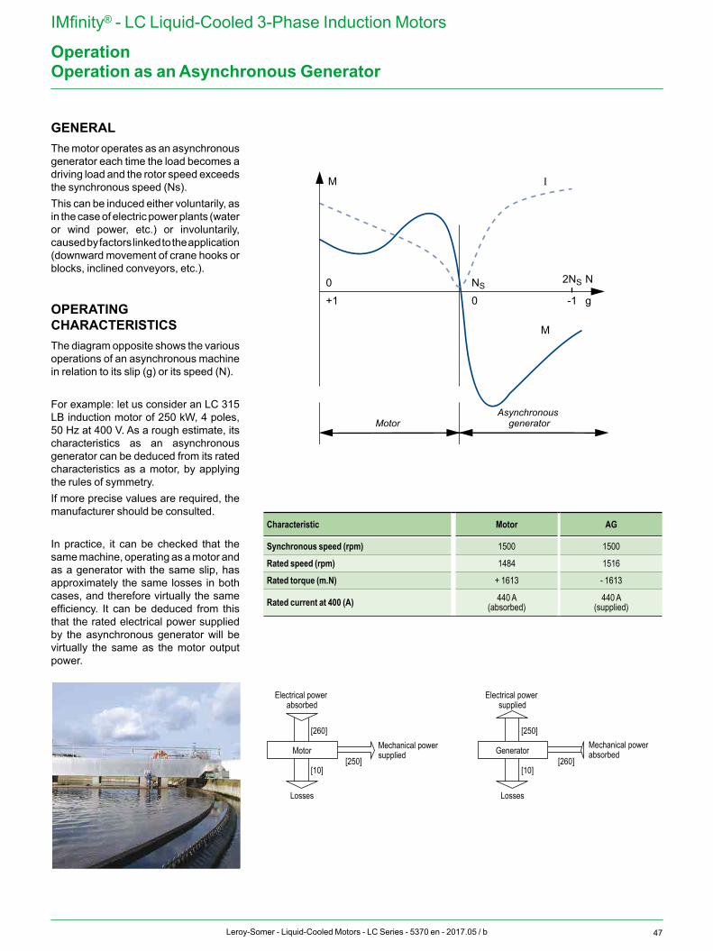
47Leroy-Somer - Liquid-Cooled Motors - LC Series - 5370 en - 2017.05 / b
IMfinity® - LC Liquid-Cooled 3-Phase Induction Motors
OperationOperation as an Asynchronous Generator
GENERALThe motor operates as an asynchronous generator each time the load becomes a driving load and the rotor speed exceeds the synchronous speed (Ns).This can be induced either voluntarily, as in the case of electric power plants (water or wind power, etc.) or involuntarily, caused by factors linked to the application (downward movement of crane hooks or blocks, inclined conveyors, etc.).
OPERATING CHARACTERISTICSThe diagram opposite shows the various operations of an asynchronous machine in relation to its slip (g) or its speed (N).
For example: let us consider an LC 315 LB induction motor of 250 kW, 4 poles, 50 Hz at 400 V. As a rough estimate, its characteristics as an asynchronous generator can be deduced from its rated characteristics as a motor, by applying the rules of symmetry.If more precise values are required, the manufacturer should be consulted.
In practice, it can be checked that the same machine, operating as a motor and as a generator with the same slip, has approximately the same losses in both cases, and therefore virtually the same efficiency. It can be deduced from this that the rated electrical power supplied by the asynchronous generator will be virtually the same as the motor output power.
Characteristic Motor AG
Synchronous speed (rpm) 1500 1500
Rated speed (rpm) 1484 1516
Rated torque (m.N) + 1613 - 1613
Rated current at 400 (A) 440 A(absorbed)
440 A(supplied)
M
0
+1
NS
0
2NS
-1
N
g
MotorAsynchronous
generator
I I
M
Mechanical power supplied
Electrical power absorbed
Losses
Motor[250]
[260]
[10]
Mechanical power absorbed
Electrical power supplied
Losses
Generator[260]
[250]
[10]
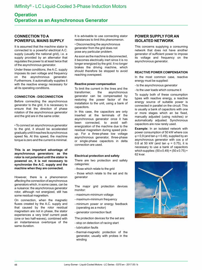
48 Leroy-Somer - Liquid-Cooled Motors - LC Series - 5370 en - 2017.05 / b
IMfinity® - LC Liquid-Cooled 3-Phase Induction Motors
OperationOperation as an Asynchronous Generator
CONNECTION TO A POWERFUL MAINS SUPPLYIt is assumed that the machine stator is connected to a powerful electrical A.C. supply (usually the national grid), i.e. a supply provided by an alternator that regulates the power to at least twice that of the asynchronous generator.Under these conditions, the A.C. supply imposes its own voltage and frequency on the asynchronous generator. Furthermore, it automatically supplies it with the reactive energy necessary for all its operating conditions.
CONNECTION - DISCONNECTIONBefore connecting the asynchronous generator to the grid, it is necessary to ensure that the direction of phase rotation of the asynchronous generator and the grid are in the same order.
• To connect an asynchronous generator to the grid, it should be accelerated gradually until it reaches its synchronous speed Ns. At this speed, the machine torque is zero and the current is minimal.
This is an important advantage of asynchronous generators: as the rotor is not polarized until the stator is powered on, it is not necessary to synchronize the A.C. supply and the machine when they are connected.
However, there is a phenomenon affecting the connection of asynchronous generators which, in some cases, can be a nuisance: the asynchronous generator rotor, although not energized, still has some residual magnetism. On connection, when the magnetic fluxes created by the A.C. supply and that caused by the rotor residual magnetism are not in phase, the stator experiences a very brief current peak (one or two half-waves), combined with an instantaneous overtorque of the same duration.
It is advisable to use connecting stator resistances to limit this phenomenon.• Disconnecting the asynchronous generator from the grid does not pose any particular problem.As soon as the machine is disconnected, it becomes electrically inert since it is no longer energized by the grid. It no longer brakes the driving machine, which should therefore be stopped to avoid reaching overspeed.
Reactive power compensationTo limit the current in the lines and the transformer, the asynchronous generator can be compensated by restoring the power factor of the installation to the unit, using a bank of capacitors.In this case, the capacitors are only inserted at the terminals of the asynchronous generator once it has been connected, to avoid self-energization of the machine due to the residual magnetism during speed pick-up. For a three-phase low voltage asynchronous generator, three-phase or single-phase capacitors in delta connection are used.
Electrical protection and safetyThere are two protection and safety categories:- those which relate to the grid- those which relate to the set and its generator
The major grid protection devices monitor:- maximum-minimum voltage- maximum-minimum frequency- minimum power or energy feedback (operating as a motor)
- generator connection fault
The protection devices for the set are: - stop on detection of racing start- lubrication faults- thermal-magnetic protection of the generator, usually with probes in the winding
POWER SUPPLY FOR AN ISOLATED NETWORKThis concerns supplying a consuming network that does not have another generator of sufficient power to impose its voltage and frequency on the asynchronous generator.
REACTIVE POWER COMPENSATIONIn the most common case, reactive energy must be supplied:- to the asynchronous generator- to the user loads which consume itTo supply both of these consumption types with reactive energy, a reactive energy source of suitable power is connected in parallel on the circuit. This is usually a bank of capacitors with one or more stages which an be fixed, manually adjusted (using notches) or automatically adjusted. Synchronous capacitors are now rarely used.Example: In an isolated network with power consumption of 50 kW where cos j = 0,9 (and tan j = 0.49), supplied by an asynchronous generator with cos j of 0.8 at 50 kW (and tan j = 0.75), it is necessary to use a bank of capacitors which supplies: (50 x 0.49) + (50 x 0.75) = 62 kvar.
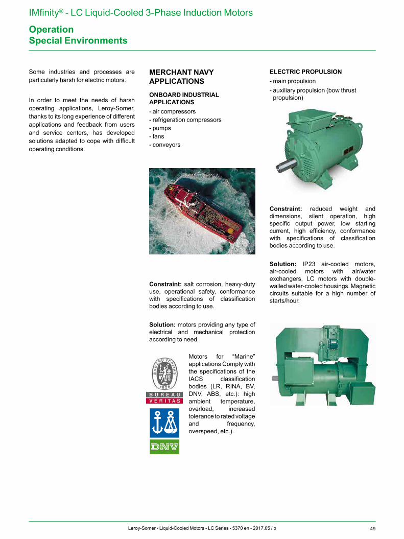
49Leroy-Somer - Liquid-Cooled Motors - LC Series - 5370 en - 2017.05 / b
IMfinity® - LC Liquid-Cooled 3-Phase Induction Motors
OperationSpecial Environments
Some industries and processes are particularly harsh for electric motors.
In order to meet the needs of harsh operating applications, Leroy-Somer, thanks to its long experience of different applications and feedback from users and service centers, has developed solutions adapted to cope with difficult operating conditions.
MERCHANT NAVY APPLICATIONS
ONBOARD INDUSTRIAL APPLICATIONS- air compressors - refrigeration compressors- pumps- fans- conveyors
Constraint: salt corrosion, heavy-duty use, operational safety, conformance with specifications of classification bodies according to use.
Solution: motors providing any type of electrical and mechanical protection according to need.
Motors for “Marine” applications Comply with the specifications of the IACS classification bodies (LR, RINA, BV, DNV, ABS, etc.): high ambient temperature, overload, increased tolerance to rated voltage and frequency, overspeed, etc.).
ELECTRIC PROPULSION- main propulsion- auxiliary propulsion (bow thrust propulsion)
Constraint: reduced weight and dimensions, silent operation, high specific output power, low starting current, high efficiency, conformance with specifications of classification bodies according to use.
Solution: IP23 air-cooled motors, air-cooled motors with air/water exchangers, LC motors with double-walled water-cooled housings. Magnetic circuits suitable for a high number of starts/hour.
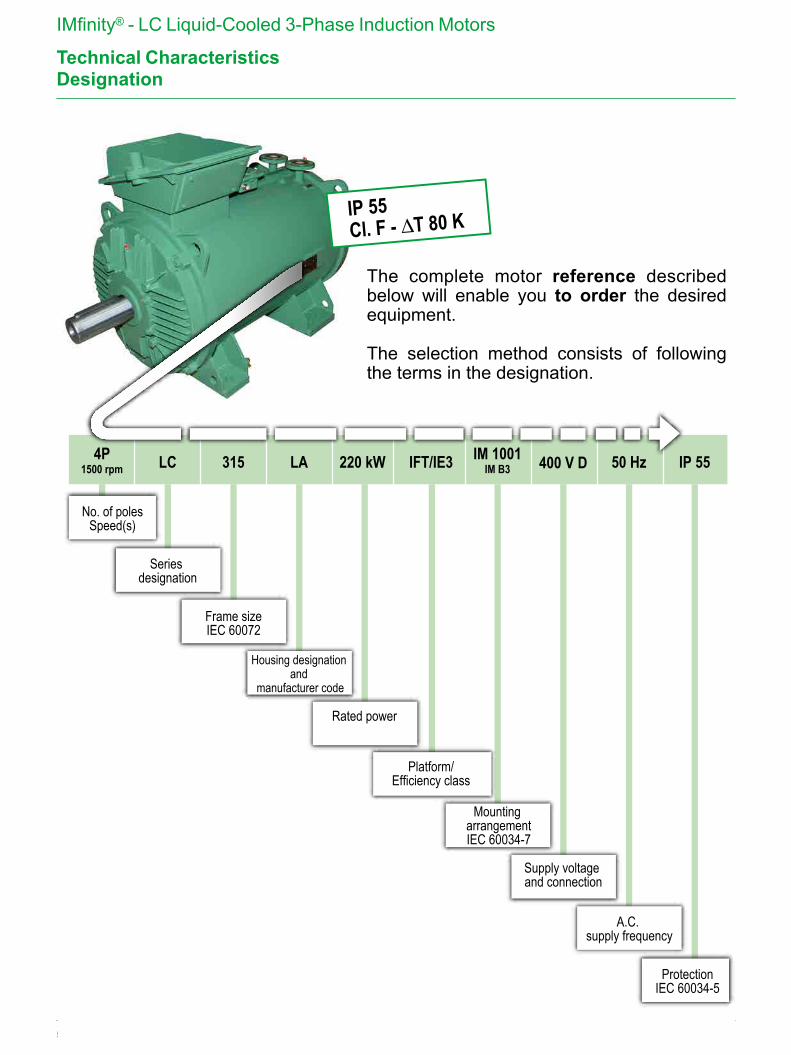
50 Leroy-Somer - Liquid-Cooled Motors - LC Series - 5370 en - 2017.05 / b
IMfinity® - LC Liquid-Cooled 3-Phase Induction Motors
Technical Characteristics
4P1500 rpm LC 315 LA IFT/IE3220 kW IM 1001
IM B3 400 V D 50 Hz IP 55
No. of polesSpeed(s)
Frame sizeIEC 60072
Platform/Efficiency class
Supply voltage and connection
ProtectionIEC 60034-5
Series designation
Housing designation and
manufacturer code
Mounting arrangementIEC 60034-7
A.C. supply frequency
IP 55Cl. F - ∆T 80 K
The complete motor reference described below will enable you to order the desired equipment.
The selection method consists of following the terms in the designation.
Rated power
Designation
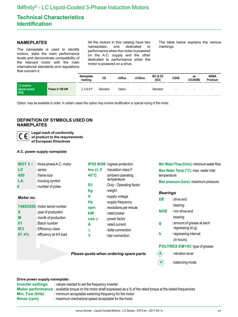
51Leroy-Somer - Liquid-Cooled Motors - LC Series - 5370 en - 2017.05 / b
IMfinity® - LC Liquid-Cooled 3-Phase Induction Motors
Technical CharacteristicsIdentification
NAMEPLATESThe nameplate is used to identify motors, state the main performance levels and demonstrate compatibility of the relevant motor with the main international standards and regulations that concern it.
All the motors in this catalog have two nameplates: one dedicated to performance when the motor is powered on the A.C. supply and the other dedicated to performance when the motor is powered on a drive.
The table below explains the various markings.
Nameplate marking CE cURus cCSAus IEC & CE
(IE3) CSAE ee(CC055B)
NEMAPremium
LC motorsliquid-cooledIP55
Power ≥ 150 kW 2, 4 & 6 P Standard Option - Standard - - -
Option: may be available to order. In certain cases this option may involve modification or special sizing of the motor.
Please quote when ordering spare parts
DEFINITION OF SYMBOLS USED ONNAMEPLATES
Legal mark of conformity of product to the requirements of European Directives
A.C. power supply nameplate
MOT 3 ~ : three-phase A.C. motor LC : series 450 : frame size LA : housing symbol4 : number of poles
Motor no.
74893200 : motor serial number X : year of production M : month of production 01 : Batch number IE3 : Efficiency class 97.4% : efficiency at 4/4 load
IP55 IK08 : ingress protectionIns cl. F : Insulation class F40°C : ambient operating
temperatureS1 : Duty - Operating factorkg : weightV : supply voltageHz : supply frequencyrpm : revolutions per minutekW : rated powercos j : power factorA : rated currentΔ : delta connectionY : star connection
Min Water Flow (l/min): minimum water flowMax Water Temp (°C): max. water inlet temperature Max pressure (bars): maximum pressure
BearingsDE : drive end bearingNDE : non drive end bearingg : amount of grease at each
regreasing (in g)h : regreasing interval (in hours)POLYREX EM103: type of grease
A : vibration level
H : balancing mode
Drive power supply nameplate:Inverter settings : values needed to set the frequency inverterMotor performance : available torque on the motor shaft expressed as a % of the rated torque at the stated frequenciesMin. Fsw (kHz) : minimum acceptable switching frequency for the motorNmax (rpm) : maximum mechanical speed acceptable for the motor
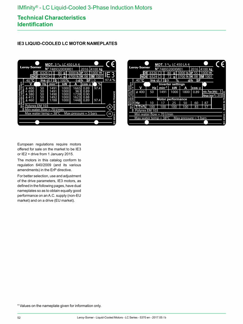
52 Leroy-Somer - Liquid-Cooled Motors - LC Series - 5370 en - 2017.05 / b
IMfinity® - LC Liquid-Cooled 3-Phase Induction Motors
Technical Characteristics
IE3 LIQUID-COOLED LC MOTOR NAMEPLATES
Identification
* Values on the nameplate given for information only.
IEC
600
34-1
- M
AD
E IN
FR
AN
CE
MOT. N° kg
V Hz kW cos ϕAmin-1S d/h SFIns cl. °C %
DENDE
IPIK
hh
gg
m
%%
IE
IEC
600
34-1
- M
AD
E IN
FR
AN
CE
MOT. N° kg
V
T/Tn%Hz
Hz kW cos ϕAminInverter settings
-1
min-1
S d/h SFIns cl. °C %
DENDE
IPIK
hh
gg
m
Motor performance
min. Fsw (kHz) :Nmax ( ) :
3
1 6100 1.0F40
LC 450 LA 4
A
H
2016 41006326 C3 80 3000 55 1000
IM 1001
IM 1001
6324 C3
Polyrex EM 103Min water �ow = 70 l/minMax water temp = 38°C Max pressure = 5 bars
Min water �ow = 70 l/minMax water temp = 38°C Max pressure = 5 bars
400690380415460
5050505060
14911491149014921788
10001000100010001000
1665 961173916231448
0.890.890.900.880.89
97.4
97.4
97.472 3700 08
74893200XM01
3
6326 C3 806324 C3 72 3700
3000
F40 9
0.89
LC 450 LA 43
32610
2016 410055 1000
Polyrex EM 103
400
10010
10017
10025
100 8350 60
5787
50 1491 1000 1800
08
74893200XM01
Modèle de marquage moteurs LCLogo EMERSON / LSEtabli par F. Boisaubert
Le 19/11/2015
Mot
eurs
Ler
oy-S
omer
Bd
Mar
celli
n Le
roy
CS1
0015
1691
5 A
ngou
lêm
e C
edex
9 -
Fran
ce
Mot
eurs
Ler
oy-S
omer
Bd
Mar
celli
n Le
roy
CS1
0015
1691
5 A
ngou
lêm
e C
edex
9 -
Fran
ce
IEC
600
34-1
- M
AD
E IN
FR
AN
CE
MOT. N° kg
V Hz kW cos ϕAmin-1S d/h SFIns cl. °C %
DENDE
IPIK
hh
gg
m
%%
IE
IEC
600
34-1
- M
AD
E IN
FR
AN
CE
MOT. N° kg
V
T/Tn%Hz
Hz kW cos ϕAminInverter settings
-1
min-1
S d/h SFIns cl. °C %
DENDE
IPIK
hh
gg
m
Motor performance
min. Fsw (kHz) :Nmax ( ) :
3
1 6100 1.0F40
LC 450 LA 4
A
H
2016 41006326 C3 80 3000 55 1000
IM 1001
IM 1001
6324 C3
Polyrex EM 103Min water �ow = 70 l/minMax water temp = 38°C Max pressure = 5 bars
Min water �ow = 70 l/minMax water temp = 38°C Max pressure = 5 bars
400690380415460
5050505060
14911491149014921788
10001000100010001000
1665 961173916231448
0.890.890.900.880.89
97.4
97.4
97.472 3700 08
74893200XM01
3
6326 C3 806324 C3 72 3700
3000
F40 9
0.89
LC 450 LA 43
32610
2016 410055 1000
Polyrex EM 103
400
10010
10017
10025
100 8350 60
5787
50 1491 1000 1800
08
74893200XM01
Modèle de marquage moteurs LCLogo EMERSON / LSEtabli par F. Boisaubert
Le 19/11/2015
Mot
eurs
Ler
oy-S
omer
Bd
Mar
celli
n Le
roy
CS1
0015
1691
5 A
ngou
lêm
e C
edex
9 -
Fran
ce
Mot
eurs
Ler
oy-S
omer
Bd
Mar
celli
n Le
roy
CS1
0015
1691
5 A
ngou
lêm
e C
edex
9 -
Fran
ce
European regulations require motors offered for sale on the market to be IE3 or IE2 + drive from 1 January 2015.The motors in this catalog conform to regulation 640/2009 (and its various amendments) in the ErP directive.For better selection, use and adjustment of the drive parameters, IE3 motors, as defined in the following pages, have dual nameplates so as to obtain equally good performance on an A.C. supply (non-EU market) and on a drive (EU market).
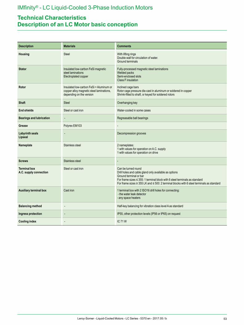
53Leroy-Somer - Liquid-Cooled Motors - LC Series - 5370 en - 2017.05 / b
IMfinity® - LC Liquid-Cooled 3-Phase Induction Motors
Technical CharacteristicsDescription of an LC Motor basic conception
Description Materials Comments
Housing Steel With lifting ringsDouble wall for circulation of water. Ground terminals
Stator Insulated low-carbon FeSi magnetic steel laminationsElectroplated copper
Fully-processed magnetic steel laminationsWelded packsSemi-enclosed slotsClass F insulation
Rotor Insulated low-carbon FeSi + Aluminum or copper alloy magnetic steel laminations, depending on the version
Inclined cage barsRotor cage pressure die-cast in aluminum or soldered in copperShrink-fitted to shaft, or keyed for soldered rotors
Shaft Steel Overhanging key
End shields Steel or cast iron Water-cooled in some cases
Bearings and lubrication - Regreasable ball bearings
Grease Polyrex EM103 -
Labyrinth sealsLipseal
- Decompression grooves
Nameplate Stainless steel 2 nameplates: 1 with values for operation on A.C. supply1 with values for operation on drive
Screws Stainless steel -
Terminal boxA.C. supply connection
Steel or cast iron Can be turned roundDrill holes and cable gland only available as optionsGround terminal or barFor frame sizes ≤ 355: 1 terminal block with 6 steel terminals as standardFor frame sizes ≥ 355 LK and ≤ 500: 2 terminal blocks with 6 steel terminals as standard
Auxiliary terminal box Cast iron 1 terminal box with 2 ISO16 drill holes for connecting: - the water leak detector- any space heaters
Balancing method - Half-key balancing for vibration class level A as standard
Ingress protection - IP55, other protection levels (IP56 or IP65) on request
Cooling index - IC 71 W
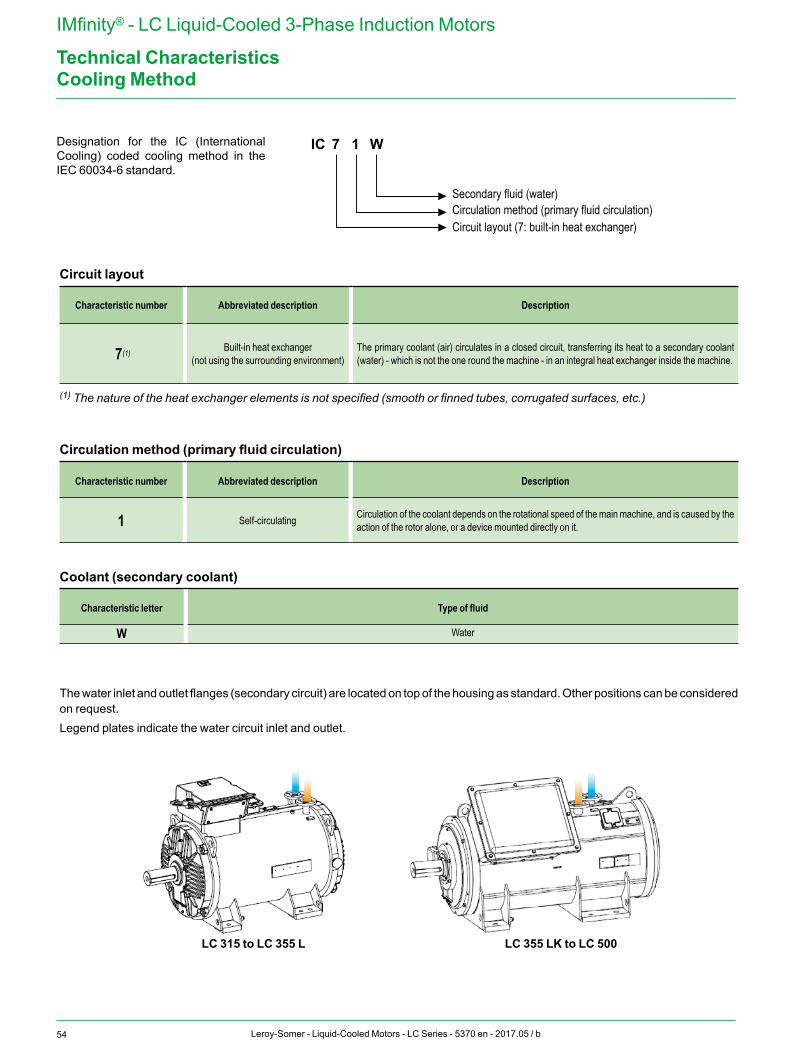
54 Leroy-Somer - Liquid-Cooled Motors - LC Series - 5370 en - 2017.05 / b
IMfinity® - LC Liquid-Cooled 3-Phase Induction Motors
Technical Characteristics
Designation for the IC (International Cooling) coded cooling method in the IEC 60034-6 standard.
Cooling Method
IC 7 1 W
Secondary fluid (water)Circulation method (primary fluid circulation)Circuit layout (7: built-in heat exchanger)
LC 315 to LC 355 L LC 355 LK to LC 500
Circuit layout
Characteristic number Abbreviated description Description
7(1) Built-in heat exchanger (not using the surrounding environment)
The primary coolant (air) circulates in a closed circuit, transferring its heat to a secondary coolant (water) - which is not the one round the machine - in an integral heat exchanger inside the machine.
(1) The nature of the heat exchanger elements is not specified (smooth or finned tubes, corrugated surfaces, etc.)
Circulation method (primary fluid circulation)
Characteristic number Abbreviated description Description
1 Self-circulating Circulation of the coolant depends on the rotational speed of the main machine, and is caused by the action of the rotor alone, or a device mounted directly on it.
Coolant (secondary coolant)
Characteristic letter Type of fluid
W Water
The water inlet and outlet flanges (secondary circuit) are located on top of the housing as standard. Other positions can be considered on request.Legend plates indicate the water circuit inlet and outlet.
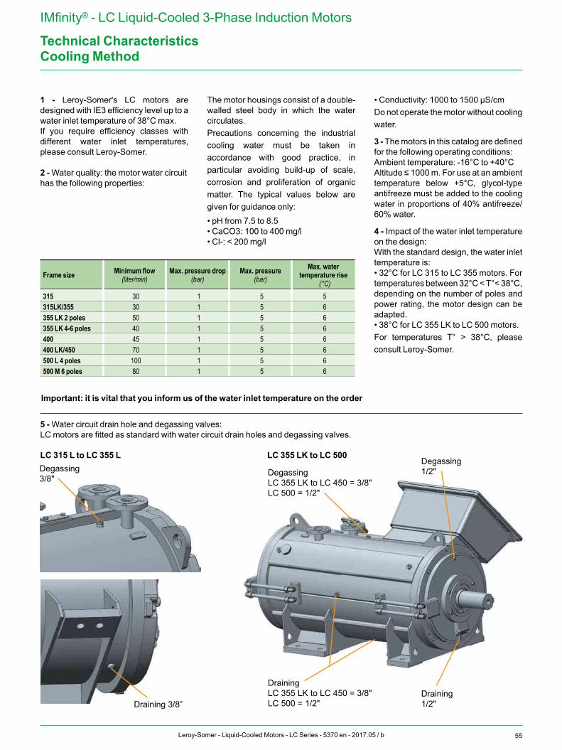
55Leroy-Somer - Liquid-Cooled Motors - LC Series - 5370 en - 2017.05 / b
IMfinity® - LC Liquid-Cooled 3-Phase Induction Motors
Technical Characteristics
1 - Leroy-Somer's LC motors are designed with IE3 efficiency level up to a water inlet temperature of 38°C max.If you require efficiency classes with different water inlet temperatures, please consult Leroy-Somer.
2 - Water quality: the motor water circuit has the following properties:
Frame size Minimum flow (liter/min)
Max. pressure drop(bar)
Max. pressure(bar)
Max. water temperature rise
(°C)315 30 1 5 5315LK/355 30 1 5 6355 LK 2 poles 50 1 5 6355 LK 4-6 poles 40 1 5 6400 45 1 5 6400 LK/450 70 1 5 6500 L 4 poles 100 1 5 6500 M 6 poles 80 1 5 6
The motor housings consist of a double-walled steel body in which the water circulates.Precautions concerning the industrial cooling water must be taken in accordance with good practice, in particular avoiding build-up of scale, corrosion and proliferation of organic matter. The typical values below are given for guidance only:
• pH from 7.5 to 8.5• CaCO3: 100 to 400 mg/l• Cl-: < 200 mg/l
• Conductivity: 1000 to 1500 µS/cmDo not operate the motor without cooling water.
3 - The motors in this catalog are defined for the following operating conditions:Ambient temperature: -16°C to +40°CAltitude ≤ 1000 m. For use at an ambient temperature below +5°C, glycol-type antifreeze must be added to the cooling water in proportions of 40% antifreeze/ 60% water.
4 - Impact of the water inlet temperature on the design:With the standard design, the water inlet temperature is:• 32°C for LC 315 to LC 355 motors. For temperatures between 32°C < T°< 38°C, depending on the number of poles and power rating, the motor design can be adapted.• 38°C for LC 355 LK to LC 500 motors.For temperatures T° > 38°C, please consult Leroy-Somer.
Cooling Method
5 - Water circuit drain hole and degassing valves:LC motors are fitted as standard with water circuit drain holes and degassing valves.
LC 315 L to LC 355 L LC 355 LK to LC 500
DegassingLC 355 LK to LC 450 = 3/8ʺLC 500 = 1/2ʺ
DrainingLC 355 LK to LC 450 = 3/8ʺLC 500 = 1/2ʺ
Degassing1/2ʺDegassing
3/8ʺ
Draining1/2ʺDraining 3/8”
Important: it is vital that you inform us of the water inlet temperature on the order
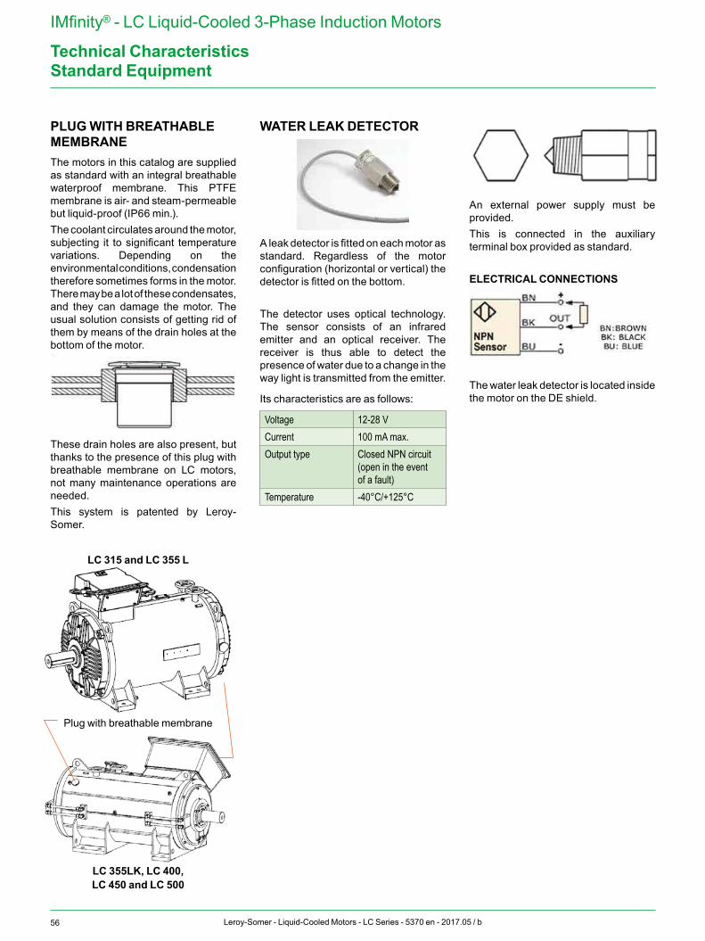
56 Leroy-Somer - Liquid-Cooled Motors - LC Series - 5370 en - 2017.05 / b
IMfinity® - LC Liquid-Cooled 3-Phase Induction Motors
Technical CharacteristicsStandard Equipment
PLUG WITH BREATHABLE MEMBRANEThe motors in this catalog are supplied as standard with an integral breathable waterproof membrane. This PTFE membrane is air- and steam-permeable but liquid-proof (IP66 min.).The coolant circulates around the motor, subjecting it to significant temperature variations. Depending on the environmental conditions, condensation therefore sometimes forms in the motor. There may be a lot of these condensates, and they can damage the motor. The usual solution consists of getting rid of them by means of the drain holes at the bottom of the motor.
These drain holes are also present, but thanks to the presence of this plug with breathable membrane on LC motors, not many maintenance operations are needed. This system is patented by Leroy-Somer.
WATER LEAK DETECTOR
A leak detector is fitted on each motor as standard. Regardless of the motor configuration (horizontal or vertical) the detector is fitted on the bottom.
The detector uses optical technology. The sensor consists of an infrared emitter and an optical receiver. The receiver is thus able to detect the presence of water due to a change in the way light is transmitted from the emitter.
Its characteristics are as follows:
Voltage 12-28 VCurrent 100 mA max.Output type Closed NPN circuit
(open in the event of a fault)
Temperature -40°C/+125°C
An external power supply must be provided.This is connected in the auxiliary terminal box provided as standard.
ELECTRICAL CONNECTIONS
The water leak detector is located inside the motor on the DE shield.
LC 315 and LC 355 L
Plug with breathable membrane
LC 355LK, LC 400, LC 450 and LC 500
57Leroy-Somer - Liquid-Cooled Motors - LC Series - 5370 en - 2017.05 / b
IMfinity® - LC Liquid-Cooled 3-Phase Induction Motors
Technical Characteristics
OPERATION ON A DRIVE• Reinforced winding insulation (Leroy-
Somer's RIS system)• Insulated ball bearing, DE and/or NDE• DE ground ring• Insulated encoder with its protective
cover
MECHANICAL ADAPTATION• Terminal box on the left or right as seen
from the drive end• Roller bearings• 2nd shaft extension• DE shaft: - differs from the catalog - tapered (10% amount of taper) - smooth without key - special key• Enlarged main terminal box for LC 315,
LC 315 LK & LC 355 L that can accommodate 2 terminal blocks.IMPORTANT: In this case only 1 auxiliary terminal box is possible, and orientation of the cable entries will be limited to left and right (180°).
• Balancing: - class B - F (full key) or N (no key)• Preparation for SPM probes: - DE and NDE: 12 hrs - 12 hrs - DE: 3 hrs – 9 hrs – 12 hrs and NDE: 3 hrs – 9 hrs – 12 hrs – axial
MOTOR PROTECTION• IP56 or IP65 protection• Thermal sensors in the windings and
endshields (PT100, PTC, KTY, PTO or PTF, thermocouples, etc.)
• Space heaters• Class H winding insulation• 2nd auxiliary terminal box (without
encoder), with 2 ISO 20 drill holes for connecting the thermal protection
• Terminal box equipment for Drive application.
Set including : - earth straps (frame housing/ terminal
body, terminal body/terminal cover, terminal cover/terminal box spacer).
- one earth bar inside terminal box. - and one terminal box spacer. This set is standard for LC 500 motors.
• Corrobloc finition (External finish syst IIIa, brass cable gland)
• brass cable gland• Full tropicalization• Non-magnetic cable gland support
plate
MISCELLANEOUS• Conformance with cURus (for the
winding insulation system)• Other paint shades
We are also able to offer on request other features such as:• Power ratings/frame sizes: < LC 315 > LC 500• Special fittings for the water inlet and
outlet• Brake
Optional Features
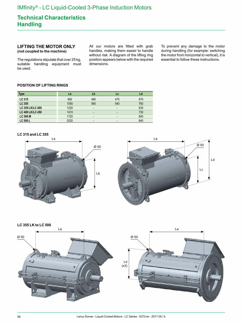
58 Leroy-Somer - Liquid-Cooled Motors - LC Series - 5370 en - 2017.05 / b
IMfinity® - LC Liquid-Cooled 3-Phase Induction Motors
Technical Characteristics
POSITION OF LIFTING RINGS
Type La Lb Lc LdLC 315 950 490 475 670LC 355 1050 560 540 760LC 355 LK/LC 400 1220 - - 630LC 400 LK/LC 450 1410 - - 730LC 500 M 1720 - - 840LC 500 L 2020 - - 840
LC 315 and LC 355
LC 355 LK to LC 500
Handling
LIFTING THE MOTOR ONLY(not coupled to the machine)
The regulations stipulate that over 25 kg, suitable handling equipment must be used.
All our motors are fitted with grab handles, making them easier to handle without risk. A diagram of the lifting ring position appears below with the required dimensions.
To prevent any damage to the motor during handling (for example: switching the motor from horizontal to vertical), it is essential to follow these instructions.
La
La La
La
Ø 50 Ø 50
Lb
Ld (x3)
Lc
Ld
Ø 50 Ø 50
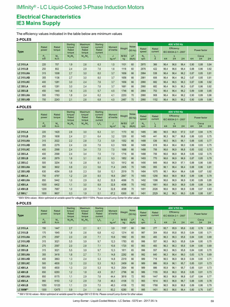
59Leroy-Somer - Liquid-Cooled Motors - LC Series - 5370 en - 2017.05 / b
IMfinity® - LC Liquid-Cooled 3-Phase Induction Motors
Electrical Characteristics
The efficiency values indicated in the table below are minimum values
4-POLES
TypeRated power
Rated torque
Starting torque/ Rated torque
Maximum torque/ Rated torque
Starting current/ Rated current
Moment of inertia Weight
Noise(50 Hz)
400 V/50 HzRated speed
Rated current
EfficiencyIEC 60034-2-1 - 2007
Power factor
Pn Mn Md/Mn Mm/Mn Id/In J IM B3 LP Nn In η Cos φkW N.m kg.m2 kg db(A) rpm A 4/4 3/4 2/4 4/4 3/4 2/4
LC 315 LA 220 1420 2,6 3,0 6,3 3,1 1170 60 1485 380 96,5 96,9 97,0 0,87 0,84 0,75LC 315 LB 250 1608 2,4 2,1 6,4 3,2 1200 60 1485 441 96,3 96,7 96,8 0,86 0,83 0,75LC 315 LKA 315 2022 2,2 2,8 7,3 5,9 1552 66 1488 536 96,5 96,5 96,1 0,88 0,85 0,77LC 315 LKB 355 2279 2,4 2,6 7,6 6,3 1606 66 1488 618 96,4 96,4 96,0 0,86 0,83 0,75LC 315 LKC 400 2568 2,4 3,4 7,5 7,0 1688 66 1488 706 96,6 96,9 96,8 0,85 0,82 0,75LC 355 LA 400 2568 2,4 3,4 7,5 7,0 1716 66 1488 706 96,6 96,9 96,8 0,85 0,82 0,75LC 355 LB 450 2879 1,6 3,1 8,0 9,3 1852 66 1493 770 96,6 96,9 96,9 0,87 0,85 0,79LC 355 LC 500 3204 1,6 2,8 8,1 9,3 1912 66 1490 849 96,6 96,9 97,1 0,88 0,86 0,80LC 355 LKA 560 3602 0,8 2,3 5,6 11,4 2405 70 1485 955 96,1 96,4 96,4 0,88 0,86 0,81LC 355 LKB 630 4054 0,8 2,3 5,6 12,1 2519 70 1484 1075 96,1 96,4 96,4 0,88 0,87 0,82LC 400 LA 750 4797 1,2 2,9 8,5 16,6 2847 70 1493 1256 96,6 96,9 96,9 0,89 0,86 0,79LC 400 LKA 850 5442 1,0 2,9 8,2 32,8 4066 70 1492 1398 96,6 96,9 96,9 0,90 0,89 0,85LC 450 LA 1000 6402 1,1 3,0 8,9 32,8 4098 70 1492 1661 96,6 96,9 96,9 0,89 0,88 0,84LC 450 LB 1200 7687 1,0 2,8 7,4 32,8 4098 70 1491 2026 96,6 96,9 96,9 0,88 0,87 0,83LC 500 L* 1500 9607 0,3 1,9 5,1 67,2 6300 80 1491 2529 96,2 96,3 96,0 0,89 0,88 0,87* 690V 50Hz values - Motor optimized at variable speed for voltage 690V Y 50Hz. Please consult Leroy-Somer for other values
6-POLES
TypeRated power
Rated torque
Starting torque/ Rated torque
Maximum torque/ Rated torque
Starting current/ Rated current
Moment of inertia Weight
Noise(50 Hz)
400 V/50 HzRated speed
Rated current
EfficiencyIEC 60034-2-1 - 2007
Power factor
Pn Mn Md/Mn Mm/Mn Id/In J IM B3 LP Nn In η Cos φkW N.m kg.m2 kg db(A) rpm A 4/4 3/4 2/4 4/4 3/4 2/4
LC 315 LA 150 1447 2,7 2,1 6,1 3,9 1157 60 990 277 95,7 95,9 95,6 0,82 0,78 0,69LC 315 LB 170 1645 1,8 2,6 6,8 4,2 1214 60 987 304 95,6 95,8 95,5 0,84 0,80 0,71LC 315 LKA 270 2597 2,0 2,8 7,1 10,6 1692 65 993 483 96,3 96,3 95,6 0,84 0,80 0,69LC 315 LKB 315 3021 5,5 3,9 9,7 12,3 1783 65 996 557 96,5 96,5 95,8 0,84 0,80 0,70LC 355 LA 270 2597 2,0 2,8 7,1 10,6 1720 65 993 483 96,3 96,3 95,6 0,84 0,80 0,69LC 355 LB 315 3021 5,5 3,9 9,7 12,3 1811 65 996 557 96,5 96,5 95,8 0,84 0,80 0,70LC 355 LKA 355 3418 1,8 2,7 7,1 14,8 2292 66 992 640 96,3 96,4 96,0 0,83 0,79 0,69LC 355 LKB 400 3863 1,3 2,4 5,3 14,8 2319 66 989 718 96,5 96,9 96,9 0,84 0,80 0,71LC 355 LKC 500 4830 1,3 2,0 5,3 16,3 2459 66 989 886 95,9 96,1 95,7 0,85 0,81 0,73LC 400 LA 500 4830 1,3 2,0 5,3 16,3 2504 66 989 886 95,9 96,1 95,7 0,85 0,81 0,73LC 400 LB 650 6293 1,2 1,8 4,9 20,7 2796 66 986 1155 95,8 96,0 95,6 0,85 0,81 0,73LC 400 LKA 850 8175 1,1 2,9 7,6 44,4 3818 72 993 1447 96,5 96,8 96,8 0,87 0,84 0,77LC 450 LA 950 9153 1,2 2,9 7,8 48,3 4106 72 993 1614 96,5 96,8 96,7 0,88 0,85 0,78LC 450 LB 1050 10120 1,1 2,9 7,0 48,3 4106 72 992 1768 96,5 96,8 96,8 0,89 0,86 0,79LC 500M** 1300 12475 0,9 2,4 6,4 83,2 6280 80 995 1401 96,5 96,6 96,4 0,80 0,76 0,67** 690 V 50 Hz values - Motor optimized at variable speed for voltage 690 V D 50 Hz. Please consult Leroy-Somer for other values
IE3 Mains Supply
2-POLES
TypeRated power
Rated torque
Starting torque/ Rated torque
Maximum torque/ Rated torque
Starting current/ Rated current
Moment of inertia Weight
Noise(50 Hz)
400 V/50 HzRated speed
Rated current
EfficiencyIEC 60034-2-1 - 2007
Power factor
Pn Mn Md/Mn Mm/Mn Id/In J IM B3 LP Nn In η Cos φkW N.m kg.m2 kg db(A) rpm A 4/4 3/4 2/4 4/4 3/4 2/4
LC 315 LA 220 707 1,9 2,6 6,3 1,5 1101 60 2970 366 96,4 96,6 96,4 0,90 0,88 0,84LC 315 LB 250 802 2,4 2,9 7,6 1,6 1118 60 2976 422 96,4 96,6 96,4 0,88 0,86 0,82LC 315 LKA 315 1008 2,7 3,0 8,0 3,7 1656 66 2984 538 96,4 96,4 96,2 0,87 0,85 0,81LC 315 LKB 355 1136 2,7 3,0 8,0 3,7 1656 66 2981 606 96,4 96,4 96,2 0,87 0,85 0,81LC 315 LKC 400 1281 3,0 2,4 7,6 3,7 1656 66 2980 682 96,4 96,5 96,3 0,87 0,86 0,82LC 355 LA 400 1281 3,0 2,4 7,6 3,7 1681 66 2980 682 96,4 96,5 96,3 0,87 0,86 0,82LC 355 LB 450 1440 1,6 2,5 5,7 4,5 1746 66 2984 753 96,4 96,4 96,2 0,89 0,88 0,85LC 355 LKA 550 1763 1,8 2,4 6,2 4,1 2253 70 2980 908 96,4 96,4 96,2 0,90 0,89 0,86LC 355 LKB 700 2243 2,1 2,6 6,8 4,5 2487 70 2980 1152 96,4 96,5 96,2 0,90 0,89 0,86
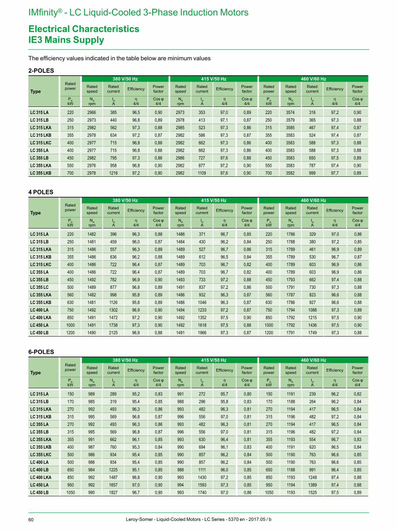
60 Leroy-Somer - Liquid-Cooled Motors - LC Series - 5370 en - 2017.05 / b
IMfinity® - LC Liquid-Cooled 3-Phase Induction Motors
Electrical Characteristics
LC 315 LA 220 2966 385 96,5 0,90 2973 353 97,0 0,89 220 3574 316 97,2 0,90LC 315 LB 250 2973 440 96,8 0,89 2978 413 97,1 0,87 250 3579 365 97,3 0,88LC 315 LKA 315 2982 562 97,3 0,88 2985 523 97,3 0,86 315 3585 467 97,4 0,87LC 315 LKB 355 2978 634 97,2 0,87 2982 586 97,3 0,87 355 3583 524 97,4 0,87LC 315 LKC 400 2977 715 96,8 0,88 2982 662 97,3 0,86 400 3583 588 97,3 0,88LC 355 LA 400 2977 715 96,8 0,88 2982 662 97,3 0,86 400 3583 588 97,3 0,88LC 355 LB 450 2982 795 97,3 0,88 2986 727 97,6 0,88 450 3583 650 97,5 0,89LC 355 LKA 550 2976 958 96,8 0,90 2982 877 97,2 0,90 550 3583 787 97,4 0,90LC 355 LKB 700 2978 1216 97,2 0,90 2982 1109 97,6 0,90 700 3582 999 97,7 0,89
4 POLES
TypeRated power
380 V/50 Hz 415 V/50 Hz 460 V/60 HzRated speed
Rated current Efficiency Power
factorRated speed
Rated current Efficiency Power
factorRated power
Rated speed
Rated current Efficiency Power
factor
Pn Nn In η Cos φ Nn In η Cos φ Pn Nn In η Cos φkW rpm A 4/4 4/4 rpm A 4/4 4/4 kW rpm A 4/4 4/4
LC 315 LA 220 1482 396 96,3 0,88 1486 371 96,7 0,85 220 1786 329 97,0 0,86LC 315 LB 250 1481 459 96,0 0,87 1484 430 96,2 0,84 250 1788 380 97,2 0,85LC 315 LKA 315 1486 557 96,3 0,89 1489 527 96,7 0,86 315 1789 461 96,9 0,89LC 315 LKB 355 1486 636 96,2 0,88 1489 612 96,5 0,84 355 1789 530 96,7 0,87LC 315 LKC 400 1486 722 96,4 0,87 1489 703 96,7 0,82 400 1789 603 96,9 0,86LC 355 LA 400 1486 722 96,4 0,87 1489 703 96,7 0,82 400 1789 603 96,9 0,86LC 355 LB 450 1492 782 96,9 0,90 1493 733 97,2 0,88 450 1793 662 97,4 0,88LC 355 LC 500 1489 877 96,8 0,89 1491 837 97,2 0,86 500 1791 730 97,3 0,88LC 355 LKA 560 1482 998 95,8 0,89 1486 932 96,3 0,87 560 1787 823 96,6 0,88LC 355 LKB 630 1481 1126 95,8 0,89 1486 1046 96,3 0,87 630 1786 927 96,6 0,88LC 400 LA 750 1492 1302 96,9 0,90 1494 1233 97,2 0,87 750 1794 1088 97,3 0,89LC 400 LKA 850 1491 1472 97,2 0,90 1492 1352 97,5 0,90 850 1792 1215 97,5 0,90LC 450 LA 1000 1491 1738 97,3 0,90 1492 1618 97,5 0,88 1000 1792 1436 97,5 0,90LC 450 LB 1200 1490 2125 96,9 0,88 1491 1966 97,3 0,87 1200 1791 1749 97,3 0,88
6-POLES
TypeRated power
380 V/50 Hz 415 V/50 Hz 460 V/60 HzRated speed
Rated current Efficiency Power
factorRated speed
Rated current Efficiency Power
factorRated power
Rated speed
Rated current Efficiency Power
factor
Pn Nn In η Cos φ Nn In η Cos φ Pn Nn In η Cos φkW rpm A 4/4 4/4 rpm A 4/4 4/4 kW rpm A 4/4 4/4
LC 315 LA 150 989 289 95,2 0,83 991 272 95,7 0,80 150 1191 239 96,2 0,82LC 315 LB 170 985 319 95,4 0,85 988 296 95,8 0,83 170 1188 264 96,2 0,84LC 315 LKA 270 992 493 96,3 0,86 993 482 96,3 0,81 270 1194 417 96,5 0,84LC 315 LKB 315 995 569 96,8 0,87 996 556 97,0 0,81 315 1196 482 97,2 0,84LC 355 LA 270 992 493 96,3 0,86 993 482 96,3 0,81 270 1194 417 96,5 0,84LC 355 LB 315 995 569 96,8 0,87 996 556 97,0 0,81 315 1196 482 97,2 0,84LC 355 LKA 355 991 662 96,1 0,85 993 630 96,4 0,81 355 1193 554 96,7 0,83LC 355 LKB 400 987 760 95,3 0,84 990 694 96,1 0,83 400 1191 620 96,5 0,84LC 355 LKC 500 986 934 95,4 0,85 990 857 96,2 0,84 500 1190 763 96,6 0,85LC 400 LA 500 986 934 95,4 0,85 990 857 96,2 0,84 500 1190 763 96,6 0,85LC 400 LB 650 984 1225 95,1 0,85 988 1111 96,0 0,85 650 1188 991 96,4 0,85LC 400 LKA 850 992 1487 96,8 0,90 993 1430 97,2 0,85 850 1193 1248 97,4 0,88LC 450 LA 950 992 1657 97,0 0,90 994 1593 97,3 0,85 950 1194 1389 97,4 0,88LC 450 LB 1050 990 1827 96,7 0,90 993 1740 97,0 0,86 1050 1193 1525 97,5 0,89
IE3 Mains Supply
2-POLES
TypeRated power
380 V/50 Hz 415 V/50 Hz 460 V/60 HzRated speed
Rated current Efficiency Power
factorRated speed
Rated current Efficiency Power
factorRated power
Rated speed
Rated current Efficiency Power
factor
Pn Nn In η Cos φ Nn In η Cos φ Pn Nn In η Cos φkW rpm A 4/4 4/4 rpm A 4/4 4/4 kW rpm A 4/4 4/4
The efficiency values indicated in the table below are minimum values
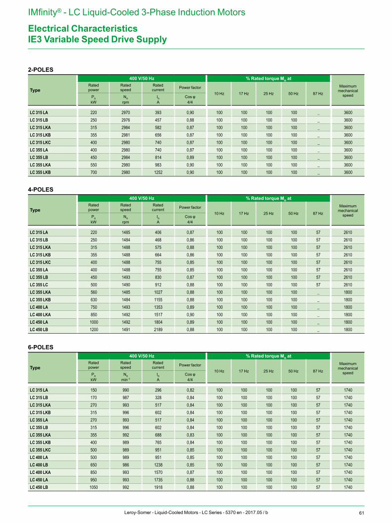
61Leroy-Somer - Liquid-Cooled Motors - LC Series - 5370 en - 2017.05 / b
IMfinity® - LC Liquid-Cooled 3-Phase Induction Motors
Electrical CharacteristicsIE3 Variable Speed Drive Supply
2-POLES
Type
400 V/50 Hz % Rated torque Mn atMaximum
mechanical speed
Rated power
Rated speed
Rated current Power factor
10 Hz 17 Hz 25 Hz 50 Hz 87 HzPn Nn In Cos φkW rpm A 4/4
LC 315 LA 220 2970 393 0,90 100 100 100 100 _ 3600LC 315 LB 250 2976 457 0,88 100 100 100 100 _ 3600LC 315 LKA 315 2984 582 0,87 100 100 100 100 _ 3600LC 315 LKB 355 2981 656 0,87 100 100 100 100 _ 3600LC 315 LKC 400 2980 740 0,87 100 100 100 100 _ 3600LC 355 LA 400 2980 740 0,87 100 100 100 100 _ 3600LC 355 LB 450 2984 814 0,89 100 100 100 100 _ 3600LC 355 LKA 550 2980 983 0,90 100 100 100 100 _ 3600LC 355 LKB 700 2980 1252 0,90 100 100 100 100 _ 3600
4-POLES
Type
400 V/50 Hz % Rated torque Mn atMaximum
mechanical speed
Rated power
Rated speed
Rated current Power factor
10 Hz 17 Hz 25 Hz 50 Hz 87 HzPn Nn In Cos φkW rpm A 4/4
LC 315 LA 220 1485 406 0,87 100 100 100 100 57 2610LC 315 LB 250 1484 468 0,86 100 100 100 100 57 2610LC 315 LKA 315 1488 575 0,88 100 100 100 100 57 2610LC 315 LKB 355 1488 664 0,86 100 100 100 100 57 2610LC 315 LKC 400 1488 755 0,85 100 100 100 100 57 2610LC 355 LA 400 1488 755 0,85 100 100 100 100 57 2610LC 355 LB 450 1493 830 0,87 100 100 100 100 57 2610LC 355 LC 500 1490 912 0,88 100 100 100 100 57 2610LC 355 LKA 560 1485 1027 0,88 100 100 100 100 _ 1800LC 355 LKB 630 1484 1155 0,88 100 100 100 100 _ 1800LC 400 LA 750 1493 1353 0,89 100 100 100 100 _ 1800LC 400 LKA 850 1492 1517 0,90 100 100 100 100 _ 1800LC 450 LA 1000 1492 1804 0,89 100 100 100 100 _ 1800LC 450 LB 1200 1491 2189 0,88 100 100 100 100 _ 1800
6-POLES
Type
400 V/50 Hz % Rated torque Mn atMaximum
mechanical speed
Rated power
Rated speed
Rated current Power factor
10 Hz 17 Hz 25 Hz 50 Hz 87 HzPn Nn In Cos φkW min-1 A 4/4
LC 315 LA 150 990 296 0,82 100 100 100 100 57 1740LC 315 LB 170 987 328 0,84 100 100 100 100 57 1740LC 315 LKA 270 993 517 0,84 100 100 100 100 57 1740LC 315 LKB 315 996 602 0,84 100 100 100 100 57 1740LC 355 LA 270 993 517 0,84 100 100 100 100 57 1740LC 355 LB 315 996 602 0,84 100 100 100 100 57 1740LC 355 LKA 355 992 688 0,83 100 100 100 100 57 1740LC 355 LKB 400 989 765 0,84 100 100 100 100 57 1740LC 355 LKC 500 989 951 0,85 100 100 100 100 57 1740LC 400 LA 500 989 951 0,85 100 100 100 100 57 1740LC 400 LB 650 986 1238 0,85 100 100 100 100 57 1740LC 400 LKA 850 993 1570 0,87 100 100 100 100 57 1740LC 450 LA 950 993 1735 0,88 100 100 100 100 57 1740LC 450 LB 1050 992 1918 0,88 100 100 100 100 57 1740
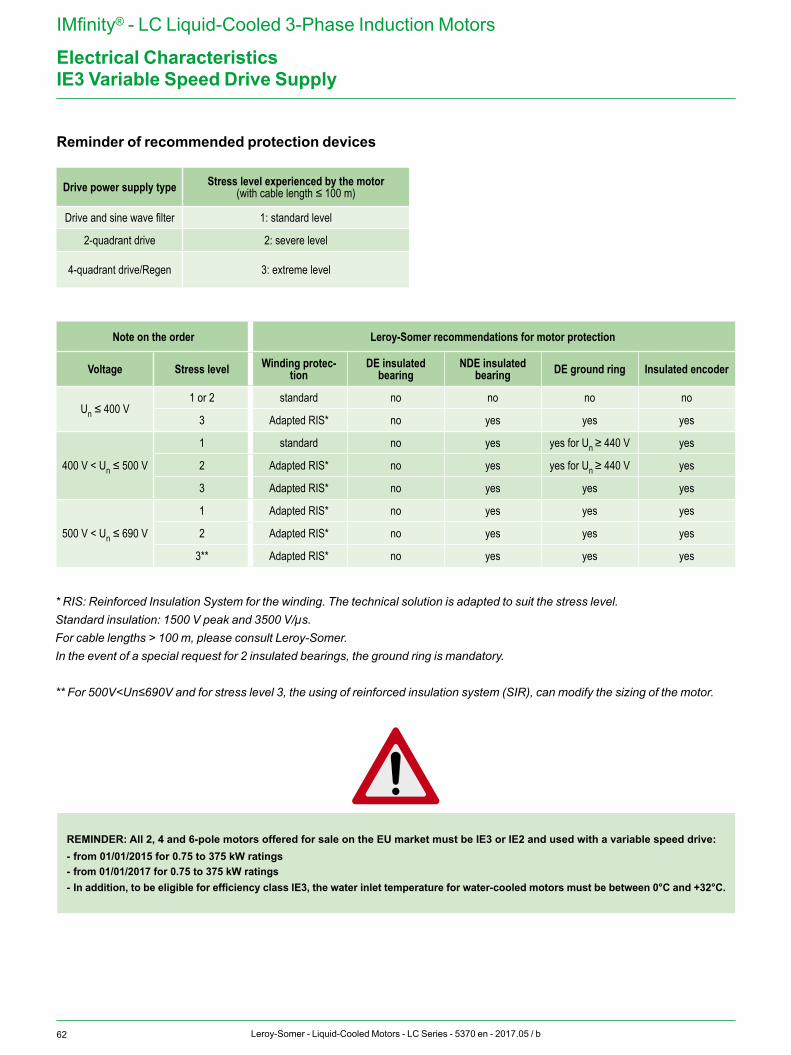
62 Leroy-Somer - Liquid-Cooled Motors - LC Series - 5370 en - 2017.05 / b
IMfinity® - LC Liquid-Cooled 3-Phase Induction Motors
Electrical CharacteristicsIE3 Variable Speed Drive Supply
Reminder of recommended protection devices
REMINDER: All 2, 4 and 6-pole motors offered for sale on the EU market must be IE3 or IE2 and used with a variable speed drive:- from 01/01/2015 for 0.75 to 375 kW ratings- from 01/01/2017 for 0.75 to 375 kW ratings- In addition, to be eligible for efficiency class IE3, the water inlet temperature for water-cooled motors must be between 0°C and +32°C.
Drive power supply type Stress level experienced by the motor(with cable length ≤ 100 m)
Drive and sine wave filter 1: standard level
2-quadrant drive 2: severe level
4-quadrant drive/Regen 3: extreme level
Note on the order Leroy-Somer recommendations for motor protection
Voltage Stress level Winding protec-tion
DE insulated bearing
NDE insulated bearing DE ground ring Insulated encoder
Un ≤ 400 V1 or 2 standard no no no no
3 Adapted RIS* no yes yes yes
400 V < Un ≤ 500 V
1 standard no yes yes for Un ≥ 440 V yes
2 Adapted RIS* no yes yes for Un ≥ 440 V yes
3 Adapted RIS* no yes yes yes
500 V < Un ≤ 690 V
1 Adapted RIS* no yes yes yes
2 Adapted RIS* no yes yes yes
3** Adapted RIS* no yes yes yes
* RIS: Reinforced Insulation System for the winding. The technical solution is adapted to suit the stress level.Standard insulation: 1500 V peak and 3500 V/µs.For cable lengths > 100 m, please consult Leroy-Somer.In the event of a special request for 2 insulated bearings, the ground ring is mandatory.
** For 500V<Un≤690V and for stress level 3, the using of reinforced insulation system (SIR), can modify the sizing of the motor.

63Leroy-Somer - Liquid-Cooled Motors - LC Series - 5370 en - 2017.05 / b
IMfinity® - LC Liquid-Cooled 3-Phase Induction Motors
Electrical CharacteristicsTerminal Block Connection
TERMINAL BLOCKSAll standard motors are supplied with a wiring diagram in the terminal box. The connector links required for coupling can be found inside the terminal box.
Tightening torque for the nuts on the terminal blocks
Terminal M4 M5 M6 M8 M10 M12 M14 M16Torque
N.m 1 2.5 4 10 20 35 50 65
Series Motor type Terminals
LC
315 LA/LB/LKA/LKB/LKCM12
355 LA/LB/LC
355 LKA/LKB
M14400 LA/LB/LKA
450 LA/LB
500 M/L M16
The usual wiring diagrams are as follows:
LC 315 L, 315 LK and 355 L motors: connection is on 6 terminals.
W2 U2 V2
L1 L2 L3
U1 V1 W1
Lowest voltage
W2 U2 V2
L1 L2 L3
U1 V1 W1
Highest voltage
LC 355 LK, 400 L, 400 LK, 450 and 500 motors: connection is on 12 terminals.
W2 W2
U1
L1 L2 L3
U1
U2 U2
V1 V1
V2 V2
W1 W1
Lowest voltage
W2 W2
U1
L1 L2 L3
U1
U2 U2
V1 V1
V2 V2
W1 W1
Highest voltage
When the motor is supplied with power by a drive, L1, L2 and L3 are replaced by the U, V and W drive connections.
DIRECTION OF ROTATIONThe direction of rotation seen from the shaft end is always found by:
L1L2L3
U1V1W1
If 2 phases of the power supply are changed over, the motor will rotate anti-clockwise (the motor should be checked first to ensure that it has been designed for both directions of rotation).
If the motor is controlled by a Powerdrive MD2, a function that can be used to reverse the direction of rotation via a parameter is available as standard, thus avoiding the need to modify the wiring.
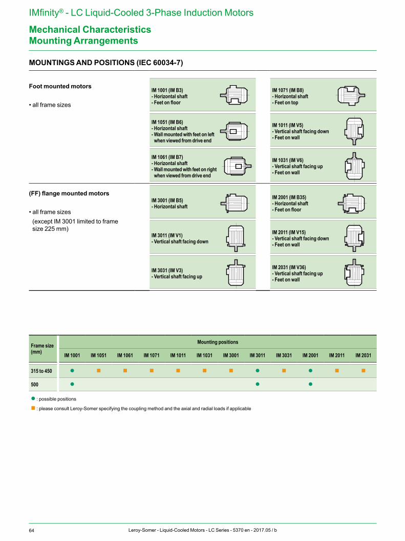
64 Leroy-Somer - Liquid-Cooled Motors - LC Series - 5370 en - 2017.05 / b
IMfinity® - LC Liquid-Cooled 3-Phase Induction Motors
Mechanical Characteristics
MOUNTINGS AND POSITIONS (IEC 60034-7)
Foot mounted motors
• all frame sizes
IM 1001 (IM B3)- Horizontal shaft- Feet on floor
IM 1071 (IM B8)- Horizontal shaft- Feet on top
IM 1051 (IM B6)- Horizontal shaft- Wall mounted with feet on left when viewed from drive end
IM 1011 (IM V5)- Vertical shaft facing down- Feet on wall
IM 1061 (IM B7)- Horizontal shaft- Wall mounted with feet on right when viewed from drive end
IM 1031 (IM V6)- Vertical shaft facing up- Feet on wall
(FF) flange mounted motors
• all frame sizes (except IM 3001 limited to frame size 225 mm)
IM 3001 (IM B5)- Horizontal shaft
IM 2001 (IM B35)- Horizontal shaft- Feet on floor
IM 3011 (IM V1)- Vertical shaft facing down
IM 2011 (IM V15)- Vertical shaft facing down- Feet on wall
IM 3031 (IM V3)- Vertical shaft facing up
IM 2031 (IM V36)- Vertical shaft facing up- Feet on wall
Frame size (mm)
Mounting positions
IM 1001 IM 1051 IM 1061 IM 1071 IM 1011 IM 1031 IM 3001 IM 3011 IM 3031 IM 2001 IM 2011 IM 2031
315 to 450 l n n n n n n l n l n n
500 l l l
l : possible positions
n : please consult Leroy-Somer specifying the coupling method and the axial and radial loads if applicable
Mounting Arrangements
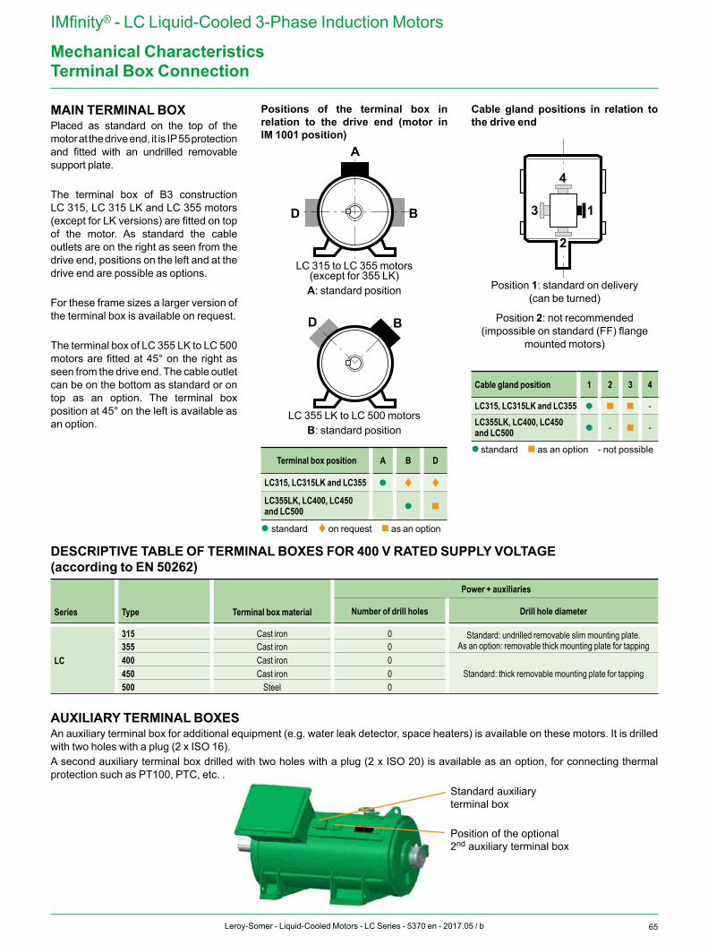
65Leroy-Somer - Liquid-Cooled Motors - LC Series - 5370 en - 2017.05 / b
IMfinity® - LC Liquid-Cooled 3-Phase Induction Motors
Mechanical Characteristics
MAIN TERMINAL BOXPlaced as standard on the top of the motor at the drive end, it is IP 55 protection and fitted with an undrilled removable support plate.
The terminal box of B3 construction LC 315, LC 315 LK and LC 355 motors (except for LK versions) are fitted on top of the motor. As standard the cable outlets are on the right as seen from the drive end, positions on the left and at the drive end are possible as options.
For these frame sizes a larger version of the terminal box is available on request.
The terminal box of LC 355 LK to LC 500 motors are fitted at 45° on the right as seen from the drive end. The cable outlet can be on the bottom as standard or on top as an option. The terminal box position at 45° on the left is available as an option.
Positions of the terminal box in relation to the drive end (motor in IM 1001 position)
2
4
13
BD
A
BD
LC 315 to LC 355 motors(except for 355 LK)A: standard position
2
4
13
BD
A
BD
LC 355 LK to LC 500 motorsB: standard position
Terminal box position A B D
LC315, LC315LK and LC355 l t t
LC355LK, LC400, LC450 and LC500 l n
l standard t on request n as an option
Cable gland positions in relation to the drive end
2
4
13
BD
A
BD
Position 1: standard on delivery (can be turned)
Position 2: not recommended (impossible on standard (FF) flange
mounted motors)
Cable gland position 1 2 3 4
LC315, LC315LK and LC355 l n n -LC355LK, LC400, LC450 and LC500 l - n -
l standard n as an option - not possible
AUXILIARY TERMINAL BOXESAn auxiliary terminal box for additional equipment (e.g. water leak detector, space heaters) is available on these motors. It is drilled with two holes with a plug (2 x ISO 16).A second auxiliary terminal box drilled with two holes with a plug (2 x ISO 20) is available as an option, for connecting thermal protection such as PT100, PTC, etc. .
Terminal Box Connection
DESCRIPTIVE TABLE OF TERMINAL BOXES FOR 400 V RATED SUPPLY VOLTAGE(according to EN 50262)
Series Type Terminal box material
Power + auxiliaries
Number of drill holes Drill hole diameter
LC
315 Cast iron 0 Standard: undrilled removable slim mounting plate.As an option: removable thick mounting plate for tapping355 Cast iron 0
400 Cast iron 0Standard: thick removable mounting plate for tapping450 Cast iron 0
500 Steel 0
Standard auxiliary terminal box
Position of the optional 2nd auxiliary terminal box
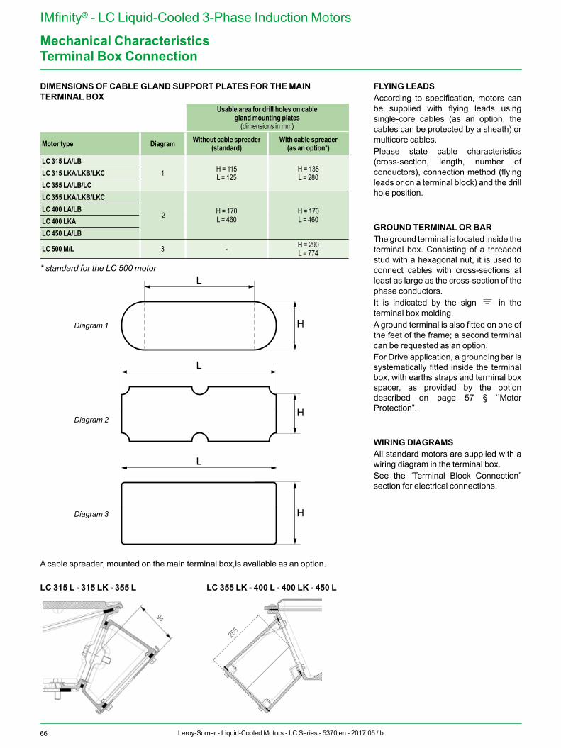
66 Leroy-Somer - Liquid-Cooled Motors - LC Series - 5370 en - 2017.05 / b
IMfinity® - LC Liquid-Cooled 3-Phase Induction Motors
Mechanical CharacteristicsTerminal Box Connection
L
H
L
H
L
H
DIMENSIONS OF CABLE GLAND SUPPORT PLATES FOR THE MAIN TERMINAL BOX
Usable area for drill holes on cable gland mounting plates
(dimensions in mm)
Motor type Diagram Without cable spreader (standard)
With cable spreader(as an option*)
LC 315 LA/LB1 H = 115
L = 125H = 135L = 280LC 315 LKA/LKB/LKC
LC 355 LA/LB/LCLC 355 LKA/LKB/LKC
2 H = 170L = 460
H = 170L = 460
LC 400 LA/LBLC 400 LKALC 450 LA/LB
LC 500 M/L 3 - H = 290L = 774
* standard for the LC 500 motor
Diagram 1
Diagram 2
Diagram 3
A cable spreader, mounted on the main terminal box,is available as an option.
FLYING LEADSAccording to specification, motors can be supplied with flying leads using single-core cables (as an option, the cables can be protected by a sheath) or multicore cables.Please state cable characteristics (cross-section, length, number of conductors), connection method (flying leads or on a terminal block) and the drill hole position.
GROUND TERMINAL OR BARThe ground terminal is located inside the terminal box. Consisting of a threaded stud with a hexagonal nut, it is used to connect cables with cross-sections at least as large as the cross-section of the phase conductors.It is indicated by the sign in the terminal box molding.A ground terminal is also fitted on one of the feet of the frame; a second terminal can be requested as an option.For Drive application, a grounding bar is systematically fitted inside the terminal box, with earths straps and terminal box spacer, as provided by the option described on page 57 § ‘’Motor Protection”.
WIRING DIAGRAMSAll standard motors are supplied with a wiring diagram in the terminal box.See the “Terminal Block Connection” section for electrical connections.
LC 355 LK - 400 L - 400 LK - 450 LLC 315 L - 315 LK - 355 L
255
94
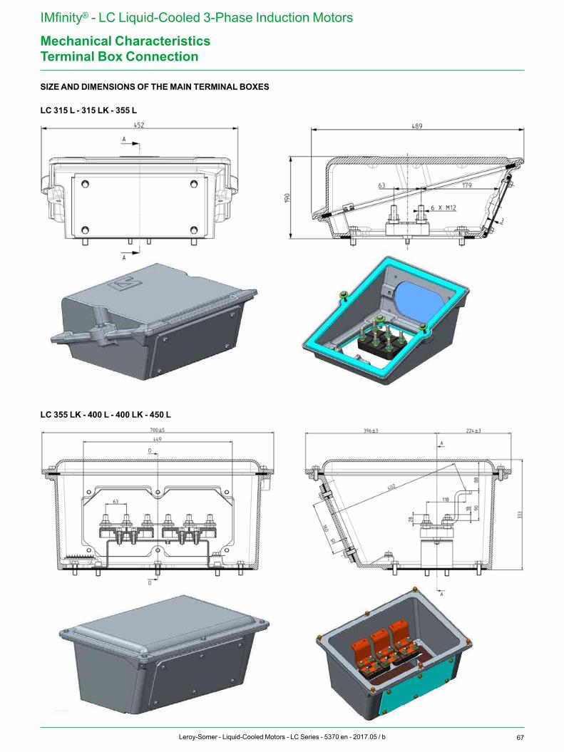
67Leroy-Somer - Liquid-Cooled Motors - LC Series - 5370 en - 2017.05 / b
IMfinity® - LC Liquid-Cooled 3-Phase Induction Motors
Mechanical CharacteristicsTerminal Box Connection
SIZE AND DIMENSIONS OF THE MAIN TERMINAL BOXES
LC 355 LK - 400 L - 400 LK - 450 L
LC 315 L - 315 LK - 355 L
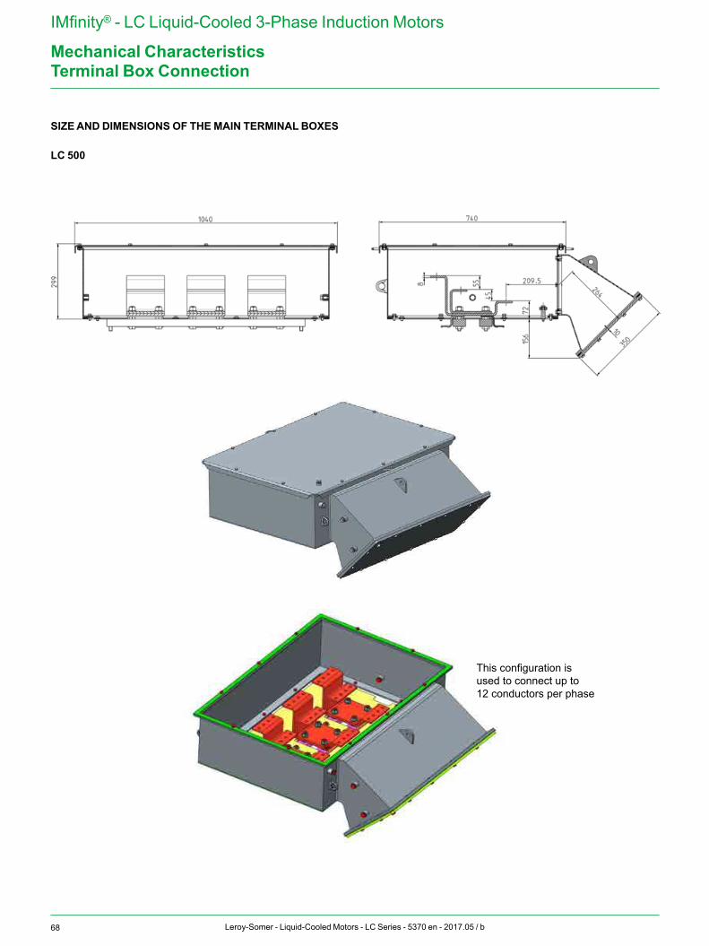
68 Leroy-Somer - Liquid-Cooled Motors - LC Series - 5370 en - 2017.05 / b
IMfinity® - LC Liquid-Cooled 3-Phase Induction Motors
Mechanical CharacteristicsTerminal Box Connection
SIZE AND DIMENSIONS OF THE MAIN TERMINAL BOXES
LC 500
This configuration is used to connect up to 12 conductors per phase
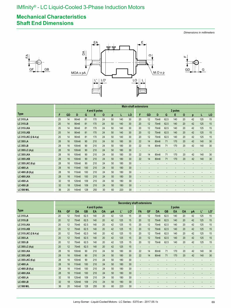
69Leroy-Somer - Liquid-Cooled Motors - LC Series - 5370 en - 2017.05 / b
IMfinity® - LC Liquid-Cooled 3-Phase Induction Motors
Mechanical CharacteristicsShaft End Dimensions
E
D
M.O x p
EA
DA
L' LO'
MOA x pA
F
GD G
FA
GF GB
LLO
Dimensions in millimeters
Type
Main shaft extensions4 and 6 poles 2 poles
F GD D G E O p L LO F GD D G E O p L LOLC 315 LA 25 14 90m6 81 170 24 50 140 30 20 12 70m6 62.5 140 20 42 125 15LC 315 LB 25 14 90m6 81 170 24 50 140 30 20 12 70m6 62.5 140 20 42 125 15LC 315 LKA 25 14 90m6 81 170 24 50 140 30 20 12 70m6 62.5 140 20 42 125 15LC 315 LKB 25 14 90m6 81 170 24 50 140 30 20 12 70m6 62.5 140 20 42 125 15LC 315 LKC (2 & 4 p) 25 14 90m6 81 170 24 50 140 30 20 12 70m6 62.5 140 20 42 125 15LC 355 LA 28 16 100m6 90 210 24 50 180 30 22 14 80m6 71 170 20 42 140 30LC 355 LB 28 16 100m6 90 210 24 50 180 30 22 14 80m6 71 170 20 42 140 30LC 355 LC (4 p) 28 16 100m6 90 210 24 50 180 30 - - - - - - - - -LC 355 LKA 28 16 100m6 90 210 24 50 180 30 22 14 80m6 71 170 20 42 140 30LC 355 LKB 28 16 100m6 90 210 24 50 180 30 22 14 80m6 71 170 20 42 140 30LC 355 LKC (6 p) 28 16 100m6 90 210 24 50 180 30 - - - - - - - - -LC 400 LA 28 16 110m6 100 210 24 50 180 30 - - - - - - - - -LC 400 LB (6 p) 28 16 110m6 100 210 24 50 180 30 - - - - - - - - -LC 400 LKA 28 16 110m6 100 210 24 50 180 30 - - - - - - - - -LC 450 LA 32 18 120m6 109 210 24 50 180 30 - - - - - - - - -LC 450 LB 32 18 120m6 109 210 24 50 180 30 - - - - - - - - -LC 500 M/L 36 20 140m6 128 250 30 60 220 30 - - - - - - - - -
Type
Secondary shaft extensions4 and 6 poles 2 poles
FA GF DA GB EA OA pA L' LO' FA GF DA GB EA OA pA L' LO'LC 315 LA 20 12 70m6 62.5 140 20 42 125 15 20 12 70m6 62.5 140 20 42 125 15LC 315 LB 20 12 70m6 62.5 140 20 42 125 15 20 12 70m6 62.5 140 20 42 125 15LC 315 LKA 20 12 70m6 62.5 140 20 42 125 15 20 12 70m6 62.5 140 20 42 125 15LC 315 LKB 20 12 70m6 62.5 140 20 42 125 15 20 12 70m6 62.5 140 20 42 125 15LC 315 LKC (2 & 4 p) 20 12 70m6 62.5 140 20 42 125 15 20 12 70m6 62.5 140 20 42 125 15LC 355 LA 20 12 70m6 62.5 140 20 42 125 15 20 12 70m6 62.5 140 20 42 125 15LC 355 LB 20 12 70m6 62.5 140 20 42 125 15 20 12 70m6 62.5 140 20 42 125 15LC 355 LC (4 p) 20 12 70m6 62.5 140 20 42 125 15 - - - - - - - - -LC 355 LKA 28 16 100m6 90 210 24 50 180 30 22 14 80m6 71 170 20 42 140 30LC 355 LKB 28 16 100m6 90 210 24 50 180 30 22 14 80m6 71 170 20 42 140 30LC 355 LKC (6 p) 28 16 100m6 90 210 24 50 180 30 - - - - - - - - -LC 400 LA 28 16 110m6 100 210 24 50 180 30 - - - - - - - - -LC 400 LB (6 p) 28 16 110m6 100 210 24 50 180 30 - - - - - - - - -LC 400 LKA 28 16 110m6 100 210 24 50 180 30 - - - - - - - - -LC 450 LA 32 18 120m6 109 210 24 50 180 30 - - - - - - - - -LC 450 LB 32 18 120m6 109 210 24 50 180 30 - - - - - - - - -LC 500 M/L 36 20 140m6 128 250 30 60 220 30 - - - - - - - - -
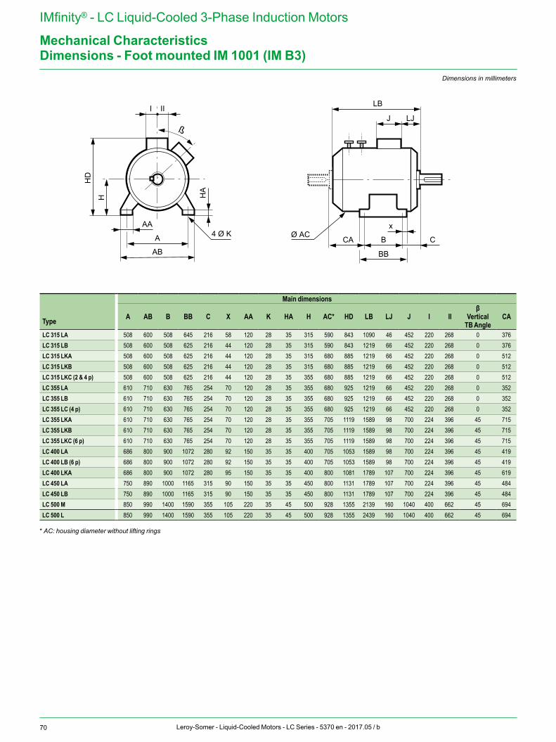
70 Leroy-Somer - Liquid-Cooled Motors - LC Series - 5370 en - 2017.05 / b
IMfinity® - LC Liquid-Cooled 3-Phase Induction Motors
Mechanical Characteristics
J LJ
LB
Ø ACx
B C
BB
CAA
HD
H HA
AB
AA4 Ø K
I II
ß
Dimensions - Foot mounted IM 1001 (IM B3)Dimensions in millimeters
Type
Main dimensions
A AB B BB C X AA K HA H AC* HD LB LJ J I IIβ
Vertical TB Angle
CA
LC 315 LA 508 600 508 645 216 58 120 28 35 315 590 843 1090 46 452 220 268 0 376LC 315 LB 508 600 508 625 216 44 120 28 35 315 590 843 1219 66 452 220 268 0 376LC 315 LKA 508 600 508 625 216 44 120 28 35 315 680 885 1219 66 452 220 268 0 512LC 315 LKB 508 600 508 625 216 44 120 28 35 315 680 885 1219 66 452 220 268 0 512LC 315 LKC (2 & 4 p) 508 600 508 625 216 44 120 28 35 355 680 885 1219 66 452 220 268 0 512LC 355 LA 610 710 630 765 254 70 120 28 35 355 680 925 1219 66 452 220 268 0 352LC 355 LB 610 710 630 765 254 70 120 28 35 355 680 925 1219 66 452 220 268 0 352LC 355 LC (4 p) 610 710 630 765 254 70 120 28 35 355 680 925 1219 66 452 220 268 0 352LC 355 LKA 610 710 630 765 254 70 120 28 35 355 705 1119 1589 98 700 224 396 45 715LC 355 LKB 610 710 630 765 254 70 120 28 35 355 705 1119 1589 98 700 224 396 45 715LC 355 LKC (6 p) 610 710 630 765 254 70 120 28 35 355 705 1119 1589 98 700 224 396 45 715LC 400 LA 686 800 900 1072 280 92 150 35 35 400 705 1053 1589 98 700 224 396 45 419LC 400 LB (6 p) 686 800 900 1072 280 92 150 35 35 400 705 1053 1589 98 700 224 396 45 419LC 400 LKA 686 800 900 1072 280 95 150 35 35 400 800 1081 1789 107 700 224 396 45 619LC 450 LA 750 890 1000 1165 315 90 150 35 35 450 800 1131 1789 107 700 224 396 45 484LC 450 LB 750 890 1000 1165 315 90 150 35 35 450 800 1131 1789 107 700 224 396 45 484LC 500 M 850 990 1400 1590 355 105 220 35 45 500 928 1355 2139 160 1040 400 662 45 694LC 500 L 850 990 1400 1590 355 105 220 35 45 500 928 1355 2439 160 1040 400 662 45 694
* AC: housing diameter without lifting rings
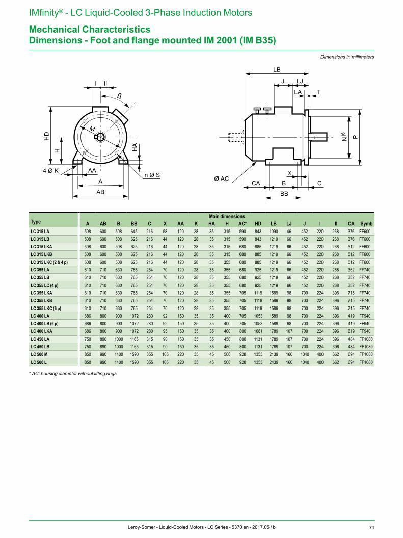
71Leroy-Somer - Liquid-Cooled Motors - LC Series - 5370 en - 2017.05 / b
IMfinity® - LC Liquid-Cooled 3-Phase Induction Motors
Mechanical Characteristics
A
HD
H
I II
HA
AB
AA
M
n Ø S4 Ø K
LA
J LJ
LB
T
x
CA B C
N Pj6
BB
ß
Ø AC
Dimensions - Foot and flange mounted IM 2001 (IM B35)Dimensions in millimeters
TypeMain dimensions
A AB B BB C X AA K HA H AC* HD LB LJ J I II CA SymbLC 315 LA 508 600 508 645 216 58 120 28 35 315 590 843 1090 46 452 220 268 376 FF600LC 315 LB 508 600 508 625 216 44 120 28 35 315 590 843 1219 66 452 220 268 376 FF600LC 315 LKA 508 600 508 625 216 44 120 28 35 315 680 885 1219 66 452 220 268 512 FF600LC 315 LKB 508 600 508 625 216 44 120 28 35 315 680 885 1219 66 452 220 268 512 FF600LC 315 LKC (2 & 4 p) 508 600 508 625 216 44 120 28 35 355 680 885 1219 66 452 220 268 512 FF600LC 355 LA 610 710 630 765 254 70 120 28 35 355 680 925 1219 66 452 220 268 352 FF740LC 355 LB 610 710 630 765 254 70 120 28 35 355 680 925 1219 66 452 220 268 352 FF740LC 355 LC (4 p) 610 710 630 765 254 70 120 28 35 355 680 925 1219 66 452 220 268 352 FF740LC 355 LKA 610 710 630 765 254 70 120 28 35 355 705 1119 1589 98 700 224 396 715 FF740LC 355 LKB 610 710 630 765 254 70 120 28 35 355 705 1119 1589 98 700 224 396 715 FF740LC 355 LKC (6 p) 610 710 630 765 254 70 120 28 35 355 705 1119 1589 98 700 224 396 715 FF740LC 400 LA 686 800 900 1072 280 92 150 35 35 400 705 1053 1589 98 700 224 396 419 FF940LC 400 LB (6 p) 686 800 900 1072 280 92 150 35 35 400 705 1053 1589 98 700 224 396 419 FF940LC 400 LKA 686 800 900 1072 280 95 150 35 35 400 800 1081 1789 107 700 224 396 619 FF940LC 450 LA 750 890 1000 1165 315 90 150 35 35 450 800 1131 1789 107 700 224 396 484 FF1080LC 450 LB 750 890 1000 1165 315 90 150 35 35 450 800 1131 1789 107 700 224 396 484 FF1080LC 500 M 850 990 1400 1590 355 105 220 35 45 500 928 1355 2139 160 1040 400 662 694 FF1080LC 500 L 850 990 1400 1590 355 105 220 35 45 500 928 1355 2439 160 1040 400 662 694 FF1080
* AC: housing diameter without lifting rings
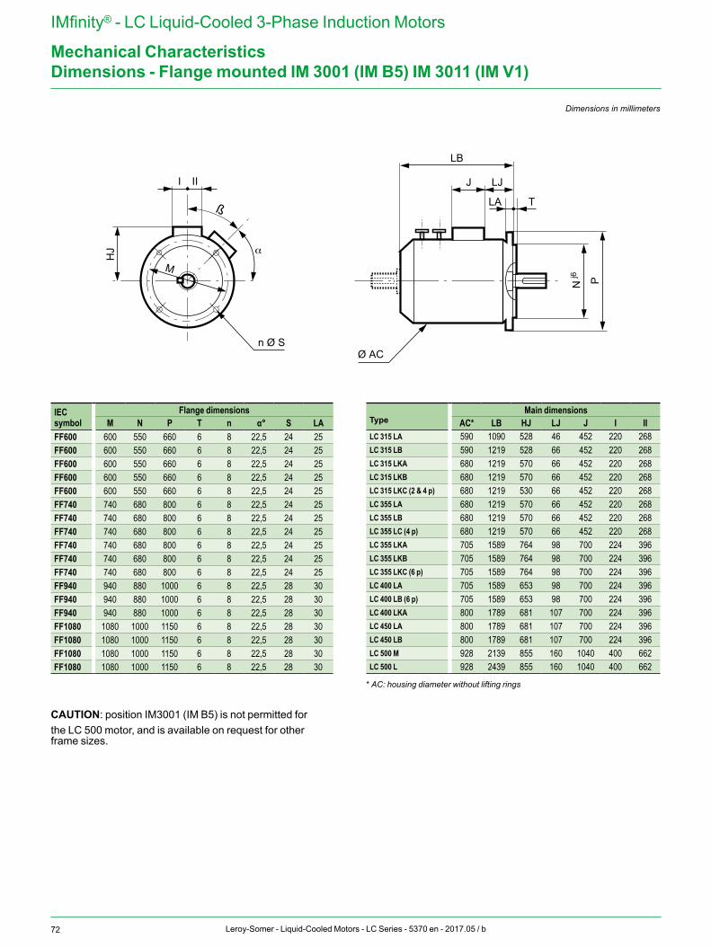
72 Leroy-Somer - Liquid-Cooled Motors - LC Series - 5370 en - 2017.05 / b
IMfinity® - LC Liquid-Cooled 3-Phase Induction Motors
Mechanical Characteristics
HJ
I II
n Ø S
LA
J LJ
LB
T
N Pj6
Ø AC
α
M
ß
Dimensions - Flange mounted IM 3001 (IM B5) IM 3011 (IM V1)
Dimensions in millimeters
IEC symbol
Flange dimensionsM N P T n α° S LA
FF600 600 550 660 6 8 22,5 24 25FF600 600 550 660 6 8 22,5 24 25FF600 600 550 660 6 8 22,5 24 25FF600 600 550 660 6 8 22,5 24 25FF600 600 550 660 6 8 22,5 24 25FF740 740 680 800 6 8 22,5 24 25FF740 740 680 800 6 8 22,5 24 25FF740 740 680 800 6 8 22,5 24 25FF740 740 680 800 6 8 22,5 24 25FF740 740 680 800 6 8 22,5 24 25FF740 740 680 800 6 8 22,5 24 25FF940 940 880 1000 6 8 22,5 28 30FF940 940 880 1000 6 8 22,5 28 30FF940 940 880 1000 6 8 22,5 28 30FF1080 1080 1000 1150 6 8 22,5 28 30FF1080 1080 1000 1150 6 8 22,5 28 30FF1080 1080 1000 1150 6 8 22,5 28 30FF1080 1080 1000 1150 6 8 22,5 28 30
CAUTION: position IM3001 (IM B5) is not permitted for the LC 500 motor, and is available on request for other frame sizes.
Main dimensionsType AC* LB HJ LJ J I IILC 315 LA 590 1090 528 46 452 220 268LC 315 LB 590 1219 528 66 452 220 268LC 315 LKA 680 1219 570 66 452 220 268LC 315 LKB 680 1219 570 66 452 220 268LC 315 LKC (2 & 4 p) 680 1219 530 66 452 220 268LC 355 LA 680 1219 570 66 452 220 268LC 355 LB 680 1219 570 66 452 220 268LC 355 LC (4 p) 680 1219 570 66 452 220 268LC 355 LKA 705 1589 764 98 700 224 396LC 355 LKB 705 1589 764 98 700 224 396LC 355 LKC (6 p) 705 1589 764 98 700 224 396LC 400 LA 705 1589 653 98 700 224 396LC 400 LB (6 p) 705 1589 653 98 700 224 396LC 400 LKA 800 1789 681 107 700 224 396LC 450 LA 800 1789 681 107 700 224 396LC 450 LB 800 1789 681 107 700 224 396LC 500 M 928 2139 855 160 1040 400 662LC 500 L 928 2439 855 160 1040 400 662
* AC: housing diameter without lifting rings
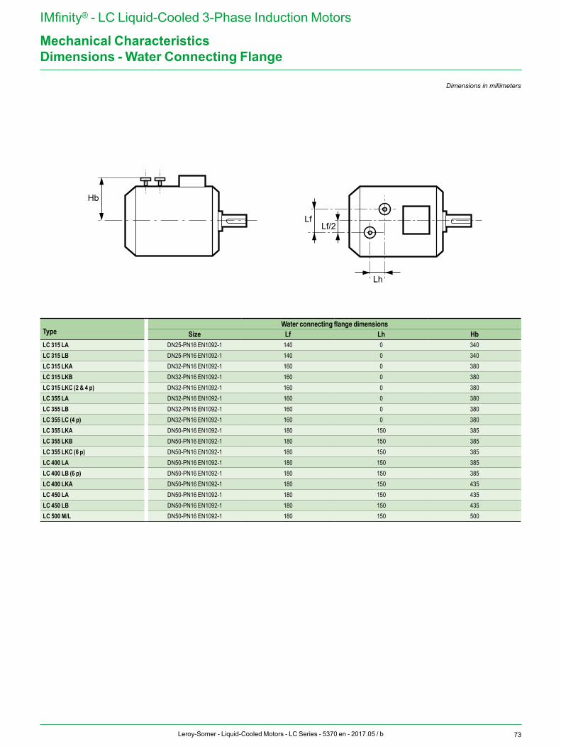
73Leroy-Somer - Liquid-Cooled Motors - LC Series - 5370 en - 2017.05 / b
IMfinity® - LC Liquid-Cooled 3-Phase Induction Motors
Mechanical Characteristics
Hb
Lh
LfLf/2
Dimensions - Water Connecting Flange
Dimensions in millimeters
TypeWater connecting flange dimensions
Size Lf Lh HbLC 315 LA DN25-PN16 EN1092-1 140 0 340LC 315 LB DN25-PN16 EN1092-1 140 0 340LC 315 LKA DN32-PN16 EN1092-1 160 0 380LC 315 LKB DN32-PN16 EN1092-1 160 0 380LC 315 LKC (2 & 4 p) DN32-PN16 EN1092-1 160 0 380LC 355 LA DN32-PN16 EN1092-1 160 0 380LC 355 LB DN32-PN16 EN1092-1 160 0 380LC 355 LC (4 p) DN32-PN16 EN1092-1 160 0 380LC 355 LKA DN50-PN16 EN1092-1 180 150 385LC 355 LKB DN50-PN16 EN1092-1 180 150 385LC 355 LKC (6 p) DN50-PN16 EN1092-1 180 150 385LC 400 LA DN50-PN16 EN1092-1 180 150 385LC 400 LB (6 p) DN50-PN16 EN1092-1 180 150 385LC 400 LKA DN50-PN16 EN1092-1 180 150 435LC 450 LA DN50-PN16 EN1092-1 180 150 435LC 450 LB DN50-PN16 EN1092-1 180 150 435LC 500 M/L DN50-PN16 EN1092-1 180 150 500
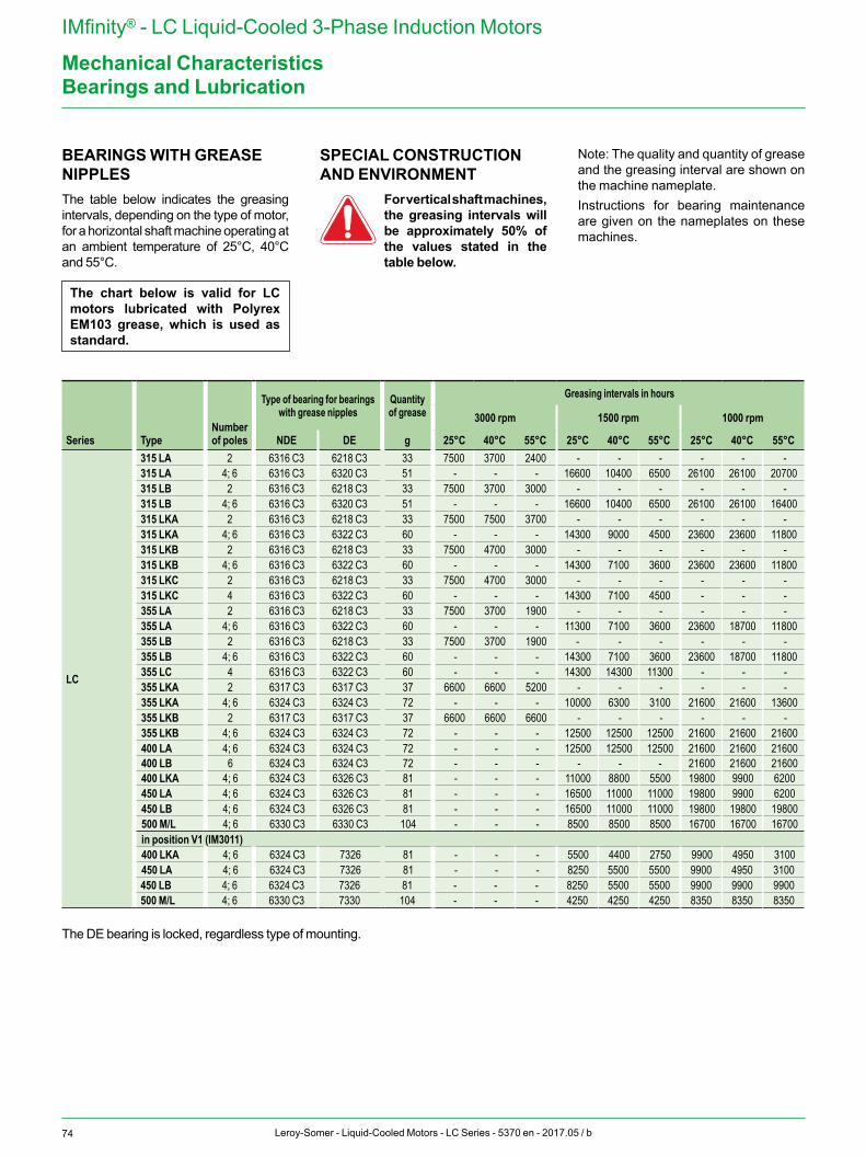
74 Leroy-Somer - Liquid-Cooled Motors - LC Series - 5370 en - 2017.05 / b
IMfinity® - LC Liquid-Cooled 3-Phase Induction Motors
Mechanical CharacteristicsBearings and Lubrication
Series TypeNumber of poles
Type of bearing for bearings with grease nipples
Quantity of grease
Greasing intervals in hours
3000 rpm 1500 rpm 1000 rpm
NDE DE g 25°C 40°C 55°C 25°C 40°C 55°C 25°C 40°C 55°C
LC
315 LA 2 6316 C3 6218 C3 33 7500 3700 2400 - - - - - -315 LA 4; 6 6316 C3 6320 C3 51 - - - 16600 10400 6500 26100 26100 20700315 LB 2 6316 C3 6218 C3 33 7500 3700 3000 - - - - - -315 LB 4; 6 6316 C3 6320 C3 51 - - - 16600 10400 6500 26100 26100 16400315 LKA 2 6316 C3 6218 C3 33 7500 7500 3700 - - - - - -315 LKA 4; 6 6316 C3 6322 C3 60 - - - 14300 9000 4500 23600 23600 11800315 LKB 2 6316 C3 6218 C3 33 7500 4700 3000 - - - - - -315 LKB 4; 6 6316 C3 6322 C3 60 - - - 14300 7100 3600 23600 23600 11800315 LKC 2 6316 C3 6218 C3 33 7500 4700 3000 - - - - - -315 LKC 4 6316 C3 6322 C3 60 - - - 14300 7100 4500 - - -355 LA 2 6316 C3 6218 C3 33 7500 3700 1900 - - - - - -355 LA 4; 6 6316 C3 6322 C3 60 - - - 11300 7100 3600 23600 18700 11800355 LB 2 6316 C3 6218 C3 33 7500 3700 1900 - - - - - -355 LB 4; 6 6316 C3 6322 C3 60 - - - 14300 7100 3600 23600 18700 11800355 LC 4 6316 C3 6322 C3 60 - - - 14300 14300 11300 - - -355 LKA 2 6317 C3 6317 C3 37 6600 6600 5200 - - - - - -355 LKA 4; 6 6324 C3 6324 C3 72 - - - 10000 6300 3100 21600 21600 13600355 LKB 2 6317 C3 6317 C3 37 6600 6600 6600 - - - - - -355 LKB 4; 6 6324 C3 6324 C3 72 - - - 12500 12500 12500 21600 21600 21600400 LA 4; 6 6324 C3 6324 C3 72 - - - 12500 12500 12500 21600 21600 21600400 LB 6 6324 C3 6324 C3 72 - - - - - - 21600 21600 21600400 LKA 4; 6 6324 C3 6326 C3 81 - - - 11000 8800 5500 19800 9900 6200450 LA 4; 6 6324 C3 6326 C3 81 - - - 16500 11000 11000 19800 9900 6200450 LB 4; 6 6324 C3 6326 C3 81 - - - 16500 11000 11000 19800 19800 19800500 M/L 4; 6 6330 C3 6330 C3 104 - - - 8500 8500 8500 16700 16700 16700in position V1 (IM3011)400 LKA 4; 6 6324 C3 7326 81 - - - 5500 4400 2750 9900 4950 3100450 LA 4; 6 6324 C3 7326 81 - - - 8250 5500 5500 9900 4950 3100450 LB 4; 6 6324 C3 7326 81 - - - 8250 5500 5500 9900 9900 9900500 M/L 4; 6 6330 C3 7330 104 - - - 4250 4250 4250 8350 8350 8350
BEARINGS WITH GREASE NIPPLESThe table below indicates the greasing intervals, depending on the type of motor, for a horizontal shaft machine operating at an ambient temperature of 25°C, 40°C and 55°C.
SPECIAL CONSTRUCTION AND ENVIRONMENT
For vertical shaft machines, the greasing intervals will be approximately 50% of the values stated in the table below.
Note: The quality and quantity of grease and the greasing interval are shown on the machine nameplate.Instructions for bearing maintenance are given on the nameplates on these machines.
The chart below is valid for LC motors lubricated with Polyrex EM103 grease, which is used as standard.
The DE bearing is locked, regardless type of mounting.
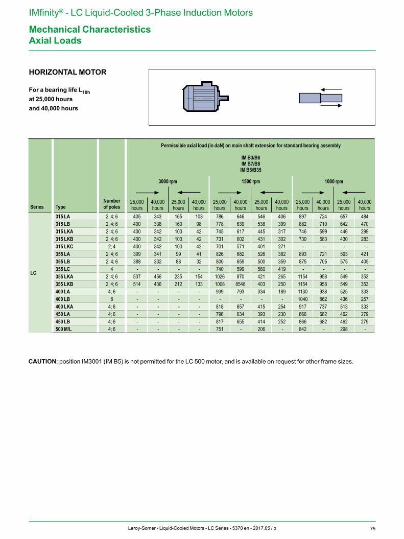
75Leroy-Somer - Liquid-Cooled Motors - LC Series - 5370 en - 2017.05 / b
IMfinity® - LC Liquid-Cooled 3-Phase Induction Motors
Mechanical CharacteristicsAxial Loads
HORIZONTAL MOTOR
For a bearing life L10hat 25,000 hoursand 40,000 hours
Series TypeNumber of poles
Permissible axial load (in daN) on main shaft extension for standard bearing assembly
IM B3/B6 IM B7/B8
IM B5/B35
3000 rpm 1500 rpm 1000 rpm
25,000 hours
40,000 hours
25,000 hours
40,000 hours
25,000 hours
40,000 hours
25,000 hours
40,000 hours
25,000 hours
40,000 hours
25,000 hours
40,000 hours
LC
315 LA 2; 4; 6 405 343 165 103 786 646 546 406 897 724 657 484315 LB 2; 4; 6 400 338 160 98 778 639 538 399 882 710 642 470315 LKA 2; 4; 6 400 342 100 42 745 617 445 317 746 599 446 299315 LKB 2; 4; 6 400 342 100 42 731 602 431 302 730 583 430 283315 LKC 2; 4 400 342 100 42 701 571 401 271 - - - -355 LA 2; 4; 6 399 341 99 41 826 682 526 382 893 721 593 421355 LB 2; 4; 6 388 332 88 32 800 659 500 359 875 705 575 405355 LC 4 - - - - 740 599 560 419 - - - -355 LKA 2; 4; 6 537 456 235 154 1026 870 421 265 1154 958 549 353355 LKB 2; 4; 6 514 436 212 133 1008 8548 403 250 1154 958 549 353400 LA 4; 6 - - - - 939 793 334 189 1130 938 525 333400 LB 6 - - - - - - - - 1040 862 436 257400 LKA 4; 6 - - - - 818 657 415 254 917 737 513 333450 LA 4; 6 - - - - 796 634 393 230 866 682 462 279450 LB 4; 6 - - - - 817 655 414 252 866 682 462 279500 M/L 4; 6 - - - - 751 - 206 - 842 - 298 -
CAUTION: position IM3001 (IM B5) is not permitted for the LC 500 motor, and is available on request for other frame sizes.
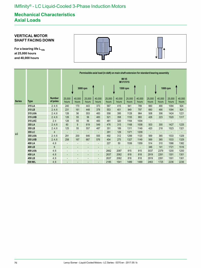
76 Leroy-Somer - Liquid-Cooled Motors - LC Series - 5370 en - 2017.05 / b
IMfinity® - LC Liquid-Cooled 3-Phase Induction Motors
Mechanical CharacteristicsAxial Loads
VERTICAL MOTOR SHAFT FACING DOWN
For a bearing life L10hat 25,000 hoursand 40,000 hours
Series TypeNumber of poles
Permissible axial load (in daN) on main shaft extension for standard bearing assembly
IM V5 IM V1/V15
3000 rpm 1500 rpm 1000 rpm
25,000 hours
40,000 hours
25,000 hours
40,000 hours
25,000 hours
40,000 hours
25,000 hours
40,000 hours
25,000 hours
40,000 hours
25,000 hours
40,000 hours
LC
315 LA 2; 4; 6 240 170 443 373 567 415 941 789 660 490 1094 924315 LB 2; 4; 6 231 161 448 378 553 401 949 797 660 490 1094 924315 LKA 2; 4; 6 126 56 553 483 558 395 1128 964 508 306 1424 1221315 LKB 2; 4; 6 126 55 56 483 521 358 1155 993 426 223 1520 1317315 LKC 2; 4 126 55 56 483 481 320 1164 1004 - - - -355 LA 2; 4; 6 60 9 619 549 476 315 1168 1008 503 300 1427 1225355 LB 2; 4; 6 125 55 557 487 351 189 1311 1149 420 218 1523 1321355 LC 4 - - - - 291 129 1371 1209 - - - -355 LKA 2; 4; 6 291 200 646 555 492 312 1299 1120 569 365 1533 1329355 LKB 2; 4; 6 258 167 667 576 454 275 1327 1149 569 365 1533 1329400 LA 4; 6 - - - - 227 50 1536 1359 514 310 1586 1382400 LB 6 - - - - - - - - 346 141 1721 1516400 LKA 4; 6 - - - - 2662 2087 815 815 3037 2379 1200 1200450 LA 4; 6 - - - - 2637 2062 818 818 2919 2261 1301 1301450 LB 4; 6 - - - - 2637 2062 818 818 2919 2261 1301 1301500 M/L 4; 6 - - - - 2185 1541 1489 1489 2463 1725 2236 2236
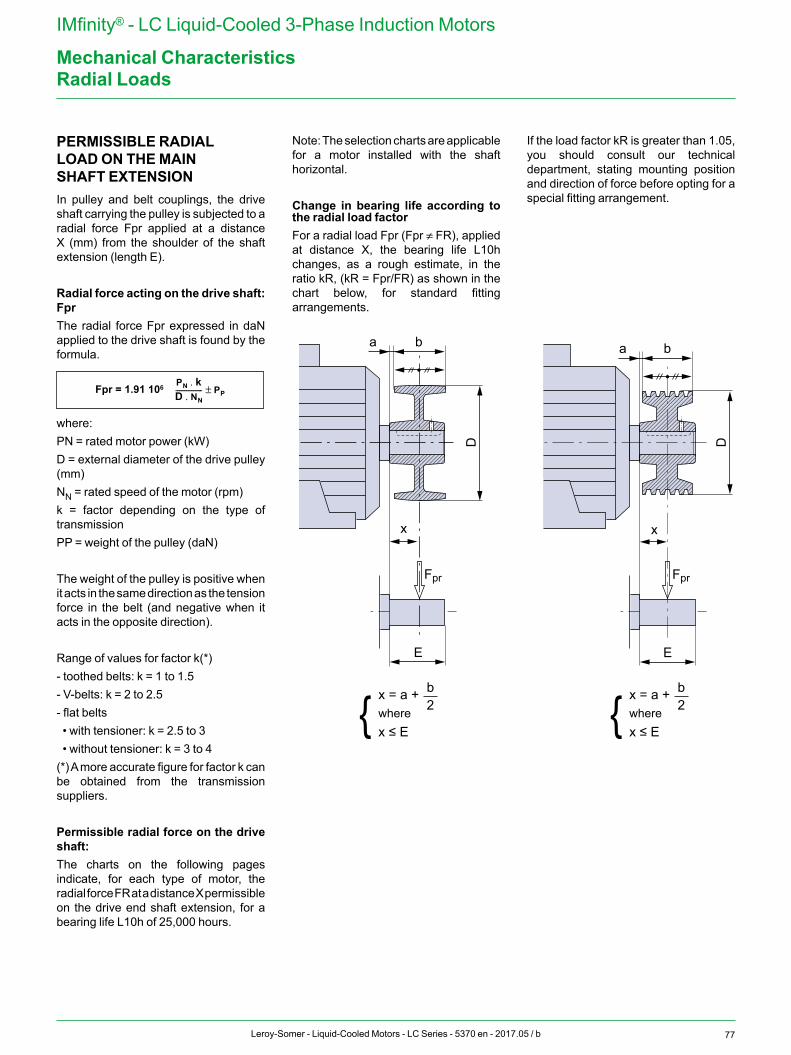
77Leroy-Somer - Liquid-Cooled Motors - LC Series - 5370 en - 2017.05 / b
IMfinity® - LC Liquid-Cooled 3-Phase Induction Motors
Mechanical CharacteristicsRadial Loads
PERMISSIBLE RADIAL LOAD ON THE MAIN SHAFT EXTENSIONIn pulley and belt couplings, the drive shaft carrying the pulley is subjected to a radial force Fpr applied at a distance X (mm) from the shoulder of the shaft extension (length E).
Radial force acting on the drive shaft: FprThe radial force Fpr expressed in daN applied to the drive shaft is found by the formula.
where:PN = rated motor power (kW)D = external diameter of the drive pulley (mm)NN = rated speed of the motor (rpm)k = factor depending on the type of transmissionPP = weight of the pulley (daN)
The weight of the pulley is positive when it acts in the same direction as the tension force in the belt (and negative when it acts in the opposite direction).
Range of values for factor k(*)- toothed belts: k = 1 to 1.5- V-belts: k = 2 to 2.5- flat belts • with tensioner: k = 2.5 to 3 • without tensioner: k = 3 to 4(*) A more accurate figure for factor k can be obtained from the transmission suppliers.
Permissible radial force on the drive shaft:The charts on the following pages indicate, for each type of motor, the radial force FR at a distance X permissible on the drive end shaft extension, for a bearing life L10h of 25,000 hours.
Fpr = 1.91 106 PN k.D NN.--------------- PP±
Note: The selection charts are applicable for a motor installed with the shaft horizontal.
Change in bearing life according to the radial load factor For a radial load Fpr (Fpr ≠ FR), applied at distance X, the bearing life L10h changes, as a rough estimate, in the ratio kR, (kR = Fpr/FR) as shown in the chart below, for standard fitting arrangements.
If the load factor kR is greater than 1.05, you should consult our technical department, stating mounting position and direction of force before opting for a special fitting arrangement.
E
Fpr
D
x
a b
E
Fpr
a b
D
x
x = a +
x ≤ Ewhere
b2{ x = a +
x ≤ Ewhere
b2{
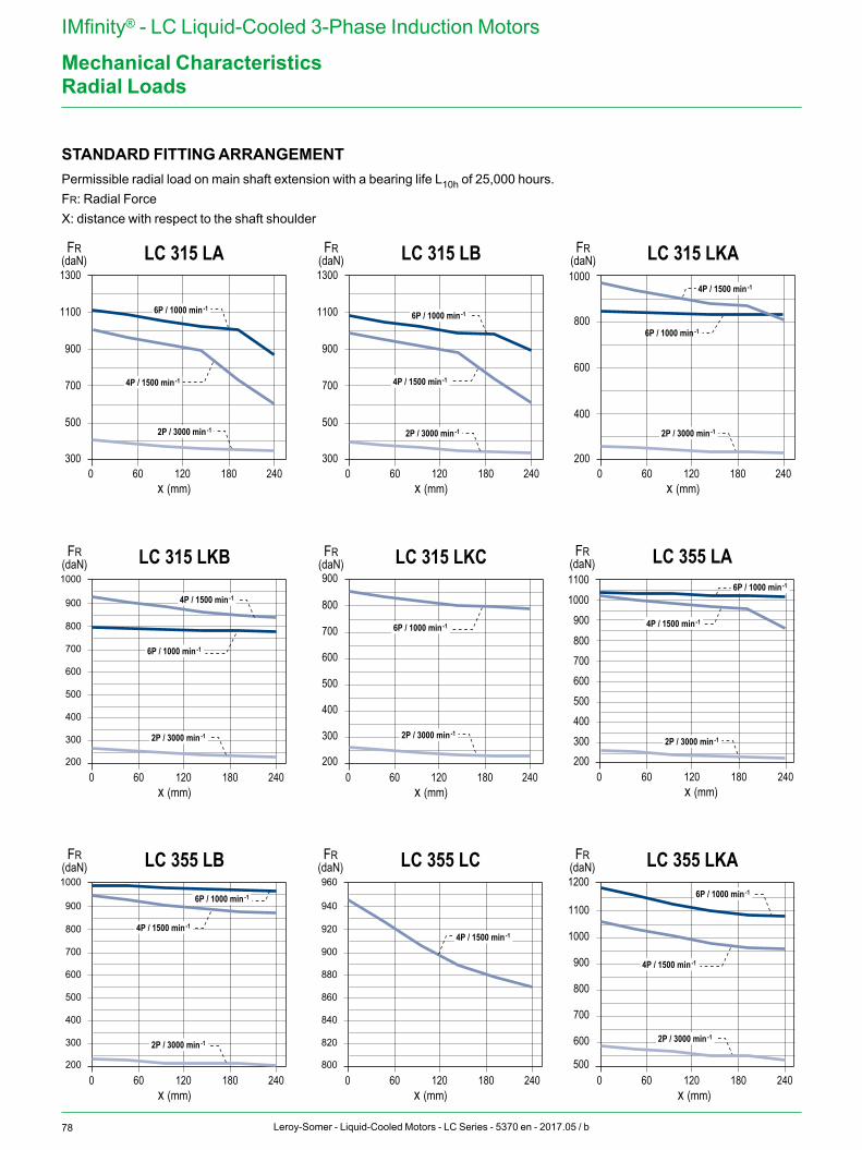
78 Leroy-Somer - Liquid-Cooled Motors - LC Series - 5370 en - 2017.05 / b
IMfinity® - LC Liquid-Cooled 3-Phase Induction Motors
Mechanical Characteristics
1300
1100
900
700
500
300600 120 180 240
x (mm)
LC 315 LAFR(daN)
2P / 3000 min -1
6P / 1000 min -1
800
900
700600500400300200
1300
1100
900
700
500
300600 120 180 240
x (mm)
LC 315 LBFR(daN)
4P / 1500 min -1 4P / 1500 min -1
800
900
700
600
500
400
300
1100
1000
900
800
700
600
200600 120 180 240
x (mm)
LC 315 LKCFR(daN)
800
900
1000
700
600
500
400
300
200600 120 180 240
x (mm)
LC 315 LKBFR(daN)
1000
1100
600 120 180 240x (mm)
LC 355 LAFR(daN)
1200
500600 120 180 240
x (mm)
LC 355 LKAFR(daN)
6P / 1000 min -1
6P / 1000 min -1
1000
800
600
400
200600 120 180 240
x (mm)
LC 315 LKAFR(daN)
2P / 3000 min -1 2P / 3000 min -1
4P / 1500 min -1
2P / 3000 min -1 2P / 3000 min -1 2P / 3000 min -1
6P / 1000 min -1
6P / 1000 min -1
6P / 1000 min -1
4P / 1500 min -1
800
900
1000
700
600
500
400
300
200600 120 180 240
x (mm)
LC 355 LBFR(daN)
2P / 3000 min -12P / 3000 min -1
6P / 1000 min -1
4P / 1500 min -1
4P / 1500 min -1
6P / 1000 min -1
920
940
960
900
880
860
840
820
800600 120 180 240
x (mm)
LC 355 LCFR(daN)
4P / 1500 min -1
4P / 1500 min -1
Radial Loads
STANDARD FITTING ARRANGEMENTPermissible radial load on main shaft extension with a bearing life L10h of 25,000 hours.FR: Radial ForceX: distance with respect to the shaft shoulder
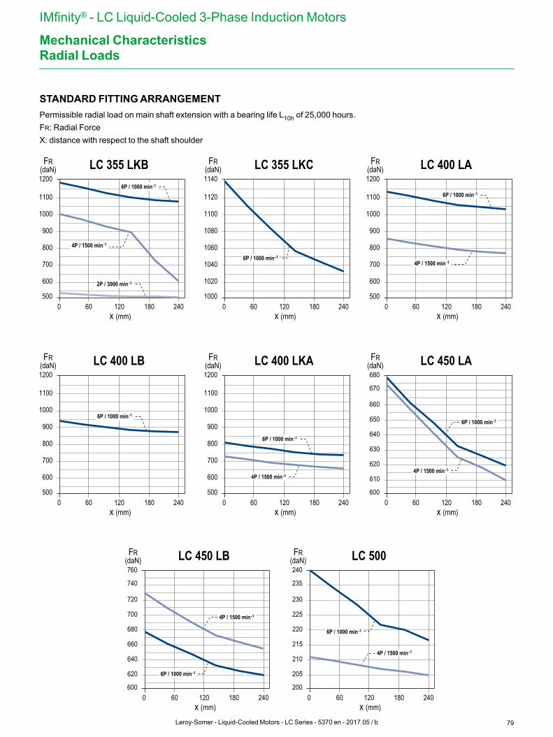
79Leroy-Somer - Liquid-Cooled Motors - LC Series - 5370 en - 2017.05 / b
IMfinity® - LC Liquid-Cooled 3-Phase Induction Motors
Mechanical Characteristics
1100
1000
900
800
700
600
1200
500600 120 180 240
x (mm)
LC 355 LKBFR(daN)
2P / 3000 min -1
4P / 1500 min -1
6P / 1000 min -1
1100
1000
900
800
700
600
1200
500600 120 180 240
x (mm)
LC 400 LBFR(daN)
6P / 1000 min -1
1100
1000
900
800
700
600
1200
500600 120 180 240
x (mm)
LC 400 LKAFR(daN)
6P / 1000 min -1
1100
1000
900
800
700
600
1200
500600 120 180 240
x (mm)
LC 400 LAFR(daN)
4P / 1500 min -1
6P / 1000 min -11120
1100
1080
1060
1040
1020
1140
1000600 120 180 240
x (mm)
LC 355 LKCFR(daN)
6P / 1000 min -1
4P / 1500 min -1
660
650
640
630
620
610
670
680
600600 120 180 240
x (mm)
LC 450 LAFR(daN)
6P / 1000 min -1
4P / 1500 min -1
720
700
680
660
640
620
740
760
600600 120 180 240
x (mm)
LC 450 LBFR(daN)
4P / 1500 min -1
6P / 1000 min -1
230
225
220
215
210
205
235
240
200600 120 180 240
x (mm)
LC 500FR(daN)
4P / 1500 min -1
6P / 1000 min -1
Radial Loads
STANDARD FITTING ARRANGEMENTPermissible radial load on main shaft extension with a bearing life L10h of 25,000 hours.FR: Radial ForceX: distance with respect to the shaft shoulder
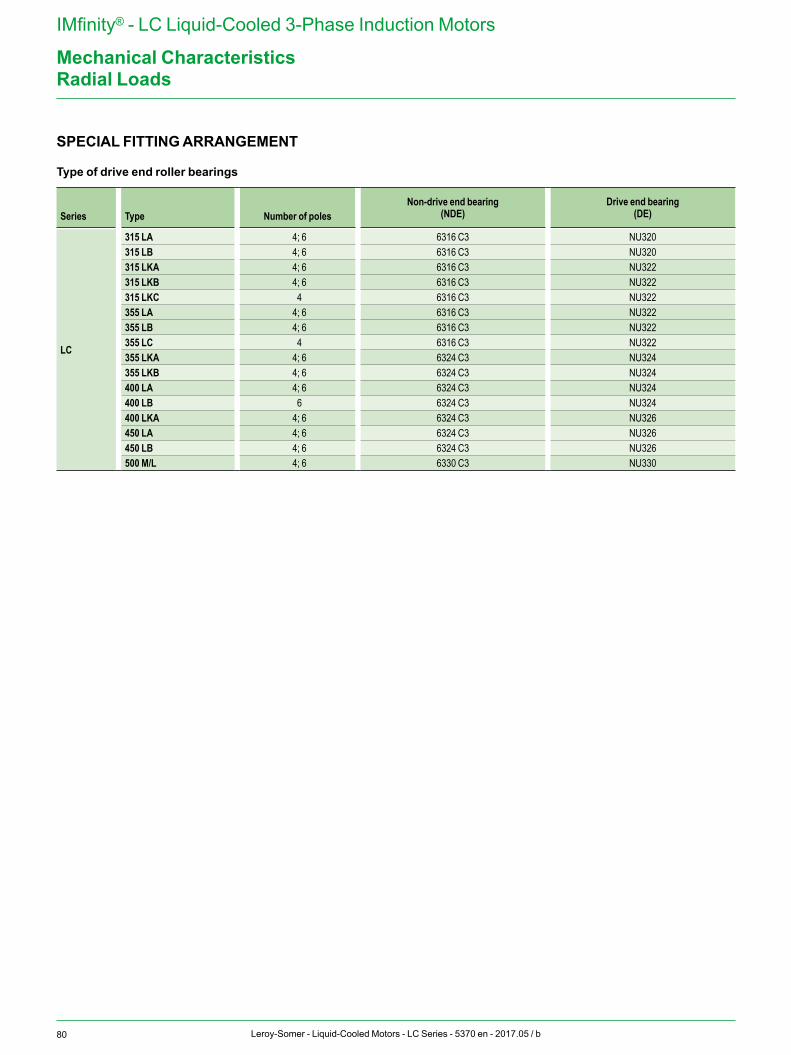
80 Leroy-Somer - Liquid-Cooled Motors - LC Series - 5370 en - 2017.05 / b
IMfinity® - LC Liquid-Cooled 3-Phase Induction Motors
Mechanical CharacteristicsRadial Loads
SPECIAL FITTING ARRANGEMENT
Type of drive end roller bearings
Series Type Number of polesNon-drive end bearing
(NDE)Drive end bearing
(DE)
LC
315 LA 4; 6 6316 C3 NU320315 LB 4; 6 6316 C3 NU320315 LKA 4; 6 6316 C3 NU322315 LKB 4; 6 6316 C3 NU322315 LKC 4 6316 C3 NU322355 LA 4; 6 6316 C3 NU322355 LB 4; 6 6316 C3 NU322355 LC 4 6316 C3 NU322355 LKA 4; 6 6324 C3 NU324355 LKB 4; 6 6324 C3 NU324400 LA 4; 6 6324 C3 NU324400 LB 6 6324 C3 NU324400 LKA 4; 6 6324 C3 NU326450 LA 4; 6 6324 C3 NU326450 LB 4; 6 6324 C3 NU326500 M/L 4; 6 6330 C3 NU330
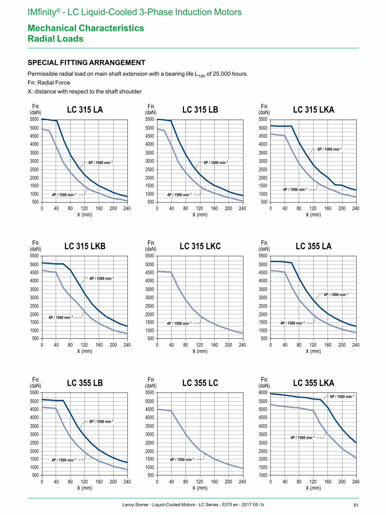
81Leroy-Somer - Liquid-Cooled Motors - LC Series - 5370 en - 2017.05 / b
IMfinity® - LC Liquid-Cooled 3-Phase Induction Motors
Mechanical Characteristics
x (mm)
LC 315 LAFR(daN)
5001000150020002500300035004000450050005500
0 40 80 120 160 200 240
4P / 1500 min -1
6P / 1000 min -1
x (mm)
LC 315 LBFR(daN)
5001000150020002500300035004000450050005500
0 40 80 120 160 200 240
4P / 1500 min -1
6P / 1000 min -1
x (mm)
LC 315 LKAFR(daN)
5001000150020002500300035004000450050005500
0 40 80 120 160 200 240
4P / 1500 min -1
6P / 1000 min -1
x (mm)
LC 315 LKBFR(daN)
5001000150020002500300035004000450050005500
0 40 80 120 160 200 240
4P / 1500 min -1
6P / 1000 min -1
x (mm)
LC 315 LKCFR(daN)
5001000150020002500300035004000450050005500
0 40 80 120 160 200 240x (mm)
LC 355 LAFR(daN)
5001000150020002500300035004000450050005500
0 40 80 120 160 200 240
4P / 1500 min -1
6P / 1000 min -1
4P / 1500 min -1
x (mm)
LC 355 LBFR(daN)
5001000150020002500300035004000450050005500
0 40 80 120 160 200 240
4P / 1500 min -1
6P / 1000 min -1
x (mm)
LC 355 LCFR(daN)
5001000150020002500300035004000450050005500
0 40 80 120 160 200 240x (mm)
LC 355 LKAFR(daN)
10001500200025003000350040004500500055006000
0 40 80 120 160 200 240
4P / 1500 min -1
6P / 1000 min -1
4P / 1500 min -1
Radial Loads
SPECIAL FITTING ARRANGEMENTPermissible radial load on main shaft extension with a bearing life L10h of 25,000 hours.FR: Radial ForceX: distance with respect to the shaft shoulder
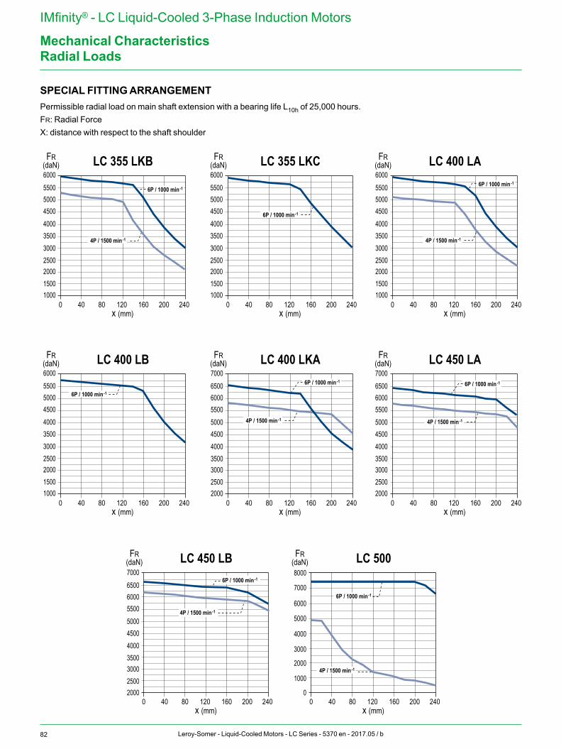
82 Leroy-Somer - Liquid-Cooled Motors - LC Series - 5370 en - 2017.05 / b
IMfinity® - LC Liquid-Cooled 3-Phase Induction Motors
Mechanical Characteristics
x (mm)
LC 355 LKBFR(daN)
10001500200025003000350040004500500055006000
10001500200025003000350040004500500055006000
10001500200025003000350040004500500055006000
10001500200025003000350040004500500055006000
0 40 80 120 160 200 240
4P / 1500 min -1
6P / 1000 min -1
x (mm)
LC 355 LKCFR(daN)
0 40 80 120 160 200 240
6P / 1000 min -1
x (mm)
LC 400 LAFR(daN)
0 40 80 120 160 200 240
x (mm)
LC 400 LBFR(daN)
0 40 80 120 160 200 240
6P / 1000 min -1
x (mm)
LC 400 LKAFR(daN)
20002500300035004000450050005500600065007000
20002500300035004000450050005500600065007000
20002500300035004000450050005500600065007000
0 40 80 120 160 200 240x (mm)
LC 450 LAFR(daN)
0 40 80 120 160 200 240
x (mm)
LC 450 LBFR(daN)
0 40 80 120 160 200 240
6P / 1000 min -1
x (mm)
LC 500FR(daN)
0
1000
2000
3000
4000
5000
6000
7000
8000
0 40 80 120 160 200 240
4P / 1500 min -1
6P / 1000 min -1
6P / 1000 min -1
6P / 1000 min -1
4P / 1500 min -1
4P / 1500 min -1
4P / 1500 min -1
6P / 1000 min -1
4P / 1500 min -1
Radial Loads
SPECIAL FITTING ARRANGEMENTPermissible radial load on main shaft extension with a bearing life L10h of 25,000 hours.FR: Radial ForceX: distance with respect to the shaft shoulder
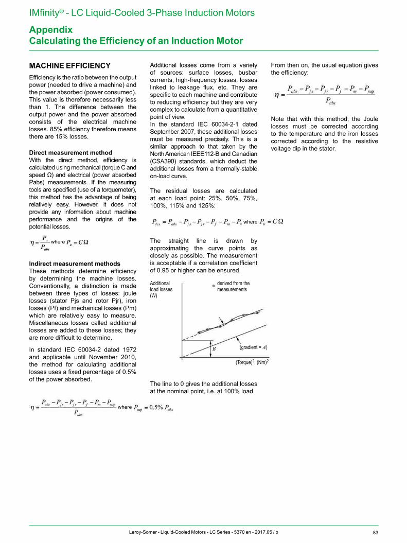
83Leroy-Somer - Liquid-Cooled Motors - LC Series - 5370 en - 2017.05 / b
IMfinity® - LC Liquid-Cooled 3-Phase Induction Motors
AppendixCalculating the Efficiency of an Induction Motor
MACHINE EFFICIENCYEfficiency is the ratio between the output power (needed to drive a machine) and the power absorbed (power consumed). This value is therefore necessarily less than 1. The difference between the output power and the power absorbed consists of the electrical machine losses. 85% efficiency therefore means there are 15% losses.
Direct measurement methodWith the direct method, efficiency is calculated using mechanical (torque C and speed Ω) and electrical (power absorbed Pabs) measurements. If the measuring tools are specified (use of a torquemeter), this method has the advantage of being relatively easy. However, it does not provide any information about machine performance and the origins of the potential losses.
Indirect measurement methods These methods determine efficiency by determining the machine losses. Conventionally, a distinction is made between three types of losses: joule losses (stator Pjs and rotor Pjr), iron losses (Pf) and mechanical losses (Pm) which are relatively easy to measure. Miscellaneous losses called additional losses are added to these losses; they are more difficult to determine.
In standard IEC 60034-2 dated 1972 and applicable until November 2010, the method for calculating additional losses uses a fixed percentage of 0.5% of the power absorbed.
Additional losses come from a variety of sources: surface losses, busbar currents, high-frequency losses, losses linked to leakage flux, etc. They are specific to each machine and contribute to reducing efficiency but they are very complex to calculate from a quantitative point of view. In the standard IEC 60034-2-1 dated September 2007, these additional losses must be measured precisely. This is a similar approach to that taken by the North American IEEE112-B and Canadian (CSA390) standards, which deduct the additional losses from a thermally-stable on-load curve.
The residual losses are calculated at each load point: 25%, 50%, 75%, 100%, 115% and 125%:
The straight line is drawn by approximating the curve points as closely as possible. The measurement is acceptable if a correlation coefficient of 0.95 or higher can be ensured.
The line to 0 gives the additional losses at the nominal point, i.e. at 100% load.
From then on, the usual equation gives the efficiency:
Note that with this method, the Joule losses must be corrected according to the temperature and the iron losses corrected according to the resistive voltage dip in the stator.
where
where
where
B
Additional load losses(W)
derived from the measurements
(gradient = A)
(Torque)2, (Nm)2
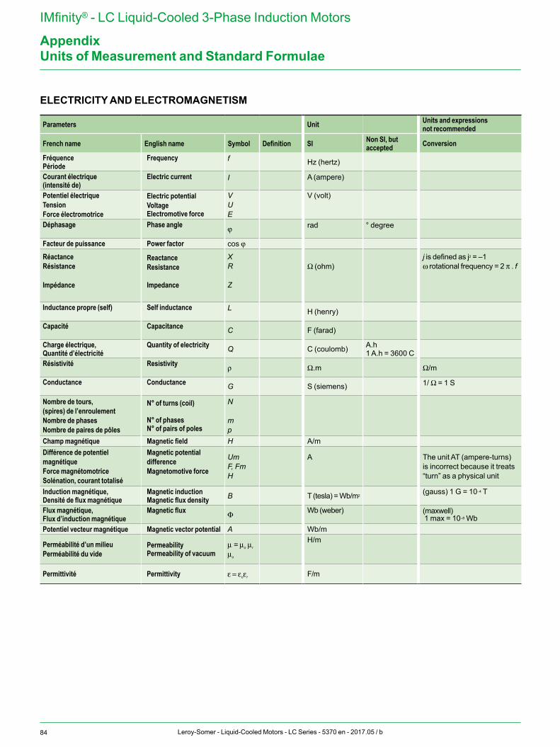
84 Leroy-Somer - Liquid-Cooled Motors - LC Series - 5370 en - 2017.05 / b
IMfinity® - LC Liquid-Cooled 3-Phase Induction Motors
Appendix
ELECTRICITY AND ELECTROMAGNETISM
Parameters Unit Units and expressionsnot recommended
French name English name Symbol Definition SI Non SI, but accepted Conversion
FréquencePériode
Frequency
f Hz (hertz)
Courant électrique(intensité de)
Electric current
I
A (ampere)
Potentiel électriqueTensionForce électromotrice
Electric potentialVoltageElectromotive force
VUE
V (volt)
Déphasage
Phase angle j rad
° degree
Facteur de puissance Power factor cos j
RéactanceRésistance
Impédance
ReactanceResistance
Impedance
XR
Z
Ω (ohm)j is defined as j2 = –1ω rotational frequency = 2 π . f
Inductance propre (self)
Self inductance
L H (henry)
Capacité
Capacitance C F (farad)
Charge électrique,Quantité d’électricité
Quantity of electricity Q C (coulomb) A.h
1 A.h = 3600 CRésistivité
Resistivity ρ Ω.m Ω/m
Conductance
Conductance G S (siemens) 1/ Ω = 1 S
Nombre de tours,(spires) de l’enroulementNombre de phasesNombre de paires de pôles
N° of turns (coil)
N° of phasesN° of pairs of poles
N
mp
Champ magnétique Magnetic field H A/mDifférence de potentiel magnétiqueForce magnétomotriceSolénation, courant totalisé
Magnetic potential differenceMagnetomotive force
UmF, FmH
A The unit AT (ampere-turns) is incorrect because it treats “turn” as a physical unit
Induction magnétique,Densité de flux magnétique
Magnetic inductionMagnetic flux density B T (tesla) = Wb/m2
(gauss) 1 G = 10–4 T
Flux magnétique,Flux d’induction magnétique
Magnetic flux Φ Wb (weber)
(maxwell) 1 max = 10–8 Wb
Potentiel vecteur magnétique Magnetic vector potential A Wb/m
Perméabilité d’un milieuPerméabilité du vide
PermeabilityPermeability of vacuum
μ = μo μr
μo
H/m
Permittivité Permittivity ε = εoεr F/m
Units of Measurement and Standard Formulae
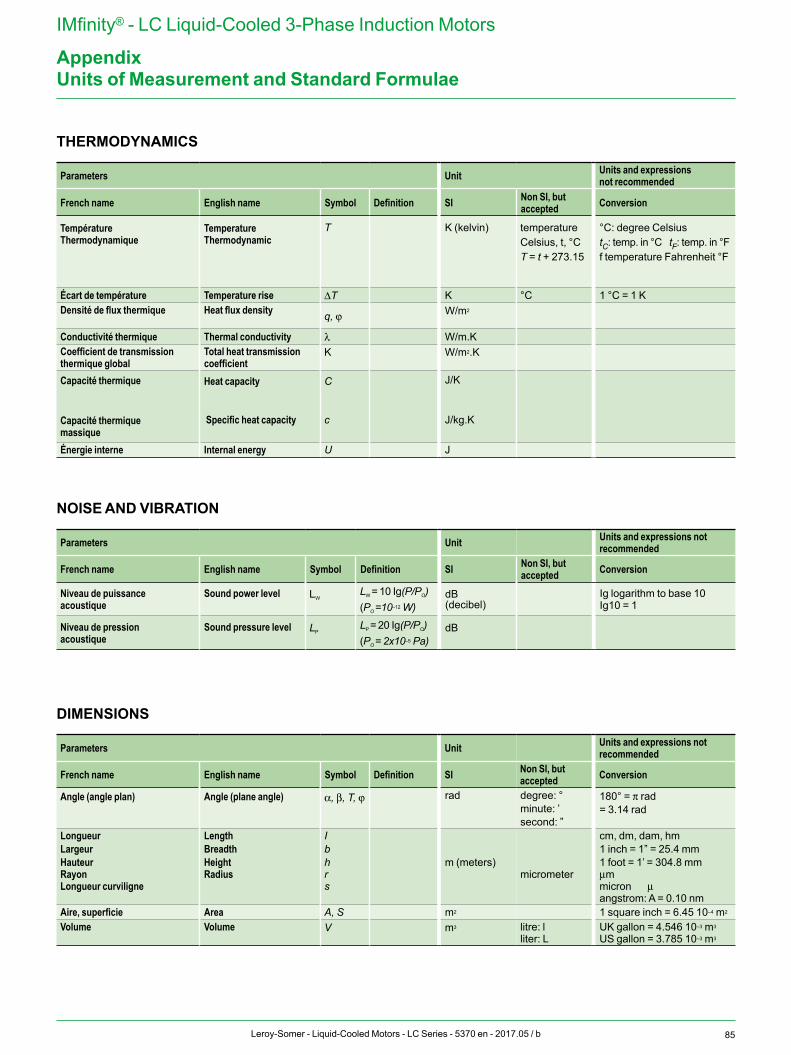
85Leroy-Somer - Liquid-Cooled Motors - LC Series - 5370 en - 2017.05 / b
IMfinity® - LC Liquid-Cooled 3-Phase Induction Motors
AppendixUnits of Measurement and Standard Formulae
THERMODYNAMICS
Parameters Unit Units and expressions not recommended
French name English name Symbol Definition SI Non SI, but accepted Conversion
TempératureThermodynamique
TemperatureThermodynamic
T K (kelvin) temperatureCelsius, t, °CT = t + 273.15
°C: degree CelsiustC: temp. in °C tF: temp. in °Ff temperature Fahrenheit °F
Écart de température Temperature rise ΔT K °C 1 °C = 1 KDensité de flux thermique
Heat flux density q, j
W/m2
Conductivité thermique Thermal conductivity λ W/m.KCoefficient de transmissionthermique global
Total heat transmissioncoefficient
K
W/m2.K
Capacité thermique
Capacité thermiquemassique
Heat capacity
Specific heat capacity
C
c
J/K
J/kg.K
Énergie interne Internal energy U J
NOISE AND VIBRATION
Parameters Unit Units and expressions not recommended
French name English name Symbol Definition SI Non SI, but accepted Conversion
Niveau de puissanceacoustique
Sound power level
LW
LW = 10 Ig(P/PO)(PO =10–12 W)
dB(decibel)
Ig logarithm to base 10Ig10 = 1
Niveau de pressionacoustique
Sound pressure level
LP
LP = 20 Ig(P/PO)(PO = 2x10⁻⁵ Pa)
dB
DIMENSIONS
Parameters Unit Units and expressions not recommended
French name English name Symbol Definition SI Non SI, but accepted Conversion
Angle (angle plan)
Angle (plane angle)
α, β, T, j
rad degree: °minute: ’second: ”
180° = π rad= 3.14 rad
LongueurLargeurHauteurRayonLongueur curviligne
LengthBreadthHeightRadius
Ibhrs
m (meters)
micrometer
cm, dm, dam, hm 1 inch = 1” = 25.4 mm1 foot = 1’ = 304.8 mmμmmicron μangstrom: A = 0.10 nm
Aire, superficie Area A, S m2 1 square inch = 6.45 10–4 m2
Volume
Volume
V
m3
litre: lliter: L
UK gallon = 4.546 10–3 m3
US gallon = 3.785 10–3 m3
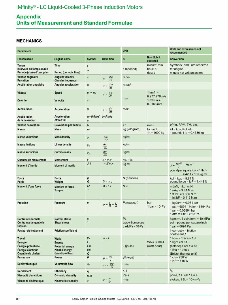
86 Leroy-Somer - Liquid-Cooled Motors - LC Series - 5370 en - 2017.05 / b
IMfinity® - LC Liquid-Cooled 3-Phase Induction Motors
Appendix
MECHANICS
Parameters Unit Units and expressions not recommended
French name English name Symbol Definition SI Non SI, but accepted Conversion
TempsIntervalle de temps, duréePériode (durée d’un cycle)
Time Period (periodic time)
t
T
s (second)
minute: minhour: hday: d
Symbols ’ and ” are reserved for anglesminute not written as mn
Vitesse angulairePulsation
Angular velocityCircular frequency
ω
rad/s
Accélération angulaire Angular acceleration
α
rad/s2
Vitesse Célérité
Speed Velocity
u, v, w,
c m/s
1 km/h =0.277,778 m/s1 m/min =0.0166 m/s
Accélération Accélérationde la pesanteur
Acceleration Accelerationof free fall
a
g = 9.81m/s2
in Paris
m/s2
Vitesse de rotation Revolution per minute N s–1 min–1 tr/mn, RPM, TM, etc.Masse Mass
m
kg (kilogram) tonne: t1 t = 1000 kg
kilo, kgs, KG, etc.1 pound: 1 Ib = 0.4536 kg
Masse volumique Mass density
ρ
kg/m3
Masse linéique Linear density
ρe
kg/m
Masse surfacique Surface mass
ρA
kg/m2
Quantité de mouvement Momentum P kg. m/s
Moment d’inertie Moment of inertia J, l kg.m2
pound per square foot = 1 lb.ft2
= 42.1 x 10⁻³ kg.m2
ForcePoids
ForceWeight
FG
N (newton) kgf = kgp = 9.81 Npound force = lbF = 4.448 N
Moment d’une force
Moment of force,Torque
MT
N.m mdaN, mkg, m.N1 mkg = 9.81 N.m1 ft.lbF = 1.356 N.m1 in.lbF = 0.113 N.m
Pression
Pressure
p Pa (pascal) bar1 bar = 105 Pa
1 kgf/cm2 = 0.981 bar1 psi = 6894 N/m2 = 6894 Pa1 psi = 0.06894 bar1 atm = 1.013 x 10⁵ Pa
Contrainte normaleContrainte tangentielle,Cission
Normal stressShear stress
στ
PaLeroy-Somer usethe MPa = 106 Pa
kg/mm2, 1 daN/mm2 = 10 MPapsi = pound per square inch1 psi = 6894 Pa
Facteur de frottement Friction coefficient
μ
incorrectly = friction coefficient ƒ
TravailÉnergieÉnergie potentielleÉnergie cinétique Quantité de chaleur
WorkEnergyPotential energyKinetic energyQuantity of heat
WEEpEk Q
J (joule)Wh = 3600 J(watt-hour)
1 N.m = 1 W.s = 1 J1 kgm = 9.81 J(calorie) 1 cal = 4.18 J1 Btu = 1055 J (British thermal unit)
Puissance Power
P
W (watt) 1 ch = 736 W1 HP = 746 W
Débit volumique Volumetric flow
qv
m3/s
Rendement Efficiency η < 1 %Viscosité dynamique Dynamic viscosity η, μ Pa.s poise, 1 P = 0.1 Pa.s
Viscosité cinématique Kinematic viscosity ν m2/s stokes, 1 St = 10–4 m2/s
Units of Measurement and Standard Formulae
p = m.vI = ∑ m.r 2
G = m.g
M = F.r
W = F.l
ω dϕdt-------=
α dωdt-------=
v dsdt------=
a dvdt------=
dmdV--------
dmdL--------
dmdS--------
p FS---- F
A----= =
P Wt
-----=
qvdVdt-------=
ν ηρ---=
2kg.mJ MD2
4------------=
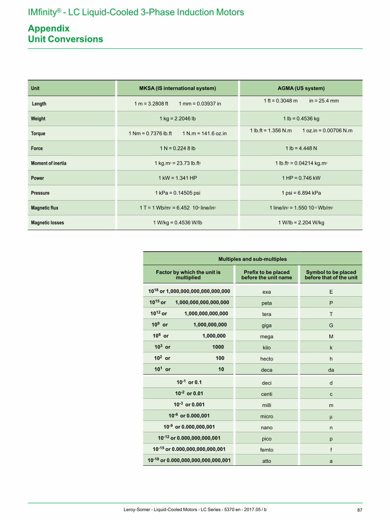
87Leroy-Somer - Liquid-Cooled Motors - LC Series - 5370 en - 2017.05 / b
IMfinity® - LC Liquid-Cooled 3-Phase Induction Motors
AppendixUnit Conversions
Unit MKSA (IS international system) AGMA (US system)
Length 1 m = 3.2808 ft 1 mm = 0.03937 in 1 ft = 0.3048 m in = 25.4 mm
Weight 1 kg = 2.2046 lb 1 lb = 0.4536 kg
Torque 1 Nm = 0.7376 lb.ft 1 N.m = 141.6 oz.in 1 lb.ft = 1.356 N.m 1 oz.in = 0.00706 N.m
Force 1 N = 0.224 8 lb 1 lb = 4.448 N
Moment of inertia 1 kg.m2 = 23.73 lb.ft2 1 lb.ft2 = 0.04214 kg.m2
Power 1 kW = 1.341 HP 1 HP = 0.746 kW
Pressure 1 kPa = 0.14505 psi 1 psi = 6.894 kPa
Magnetic flux 1 T = 1 Wb/m2 = 6.452 104 line/in2 1 line/in2 = 1.550 10–5 Wb/m2
Magnetic losses 1 W/kg = 0.4536 W/lb 1 W/lb = 2.204 W/kg
Multiples and sub-multiples
Factor by which the unit is multiplied
Prefix to be placed before the unit name
Symbol to be placed before that of the unit
1018 or 1,000,000,000,000,000,000 exa E
1015 or 1,000,000,000,000,000 peta P
1012 or 1,000,000,000,000 tera T
109 or 1,000,000,000 giga G
106 or 1,000,000 mega M
103 or 1000 kilo k
102 or 100 hecto h
101 or 10 deca da
10-1 or 0.1 deci d
10-2 or 0.01 centi c
10-3 or 0.001 milli m
10-6 or 0.000,001 micro μ
10-9 or 0.000,000,001 nano n
10-12 or 0.000,000,000,001 pico p
10-15 or 0.000,000,000,000,001 femto f
10-18 or 0.000,000,000,000,000,001 atto a
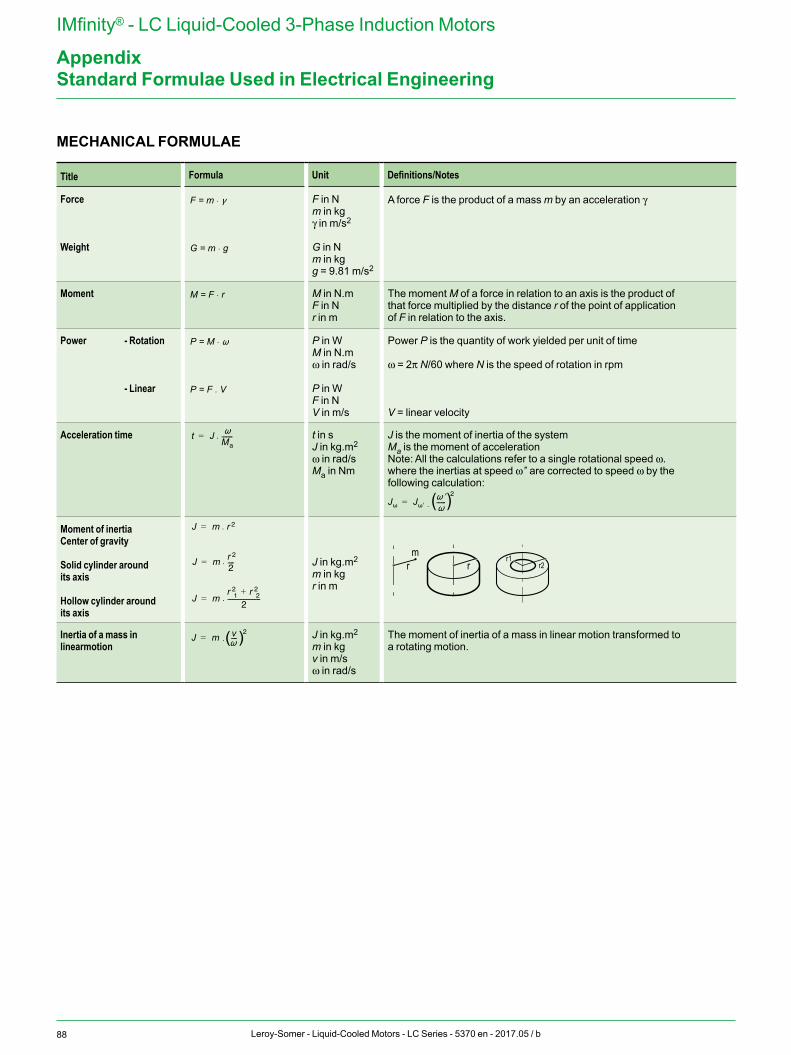
88 Leroy-Somer - Liquid-Cooled Motors - LC Series - 5370 en - 2017.05 / b
IMfinity® - LC Liquid-Cooled 3-Phase Induction Motors
AppendixStandard Formulae Used in Electrical Engineering
MECHANICAL FORMULAE
Title Formula Unit Definitions/Notes
Force
Weight
F in Nm in kgγ in m/s2
G in Nm in kgg = 9.81 m/s2
A force F is the product of a mass m by an acceleration γ
Moment M in N.mF in Nr in m
The moment M of a force in relation to an axis is the product of that force multiplied by the distance r of the point of application of F in relation to the axis.
Power - Rotation
- Linear
P in WM in N.mω in rad/s
P in WF in NV in m/s
Power P is the quantity of work yielded per unit of time
ω = 2π N/60 where N is the speed of rotation in rpm
V = linear velocity
Acceleration time t in sJ in kg.m2
ω in rad/sMa in Nm
J is the moment of inertia of the systemMa is the moment of accelerationNote: All the calculations refer to a single rotational speed ω.where the inertias at speed ω’’ are corrected to speed ω by the following calculation:
Moment of inertiaCenter of gravity
Solid cylinder around its axis
Hollow cylinder around its axis
J in kg.m2
m in kgr in m
r1r2rr
m
r1r2rr
m
Inertia of a mass in linearmotion
J in kg.m2
m in kgv in m/sω in rad/s
The moment of inertia of a mass in linear motion transformed to a rotating motion.
F = m .
G = m . g
M = F . r
P = M .
P = F .
.
.
V
t JMa-------=
J m r 2=
J m r 2
2----=
J mr 2
1 r 22+
2---------------------=
J m v----2
=
.
.
.
J J ------2
= . ( )
( )
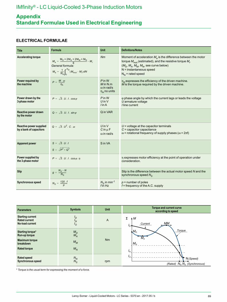
89Leroy-Somer - Liquid-Cooled Motors - LC Series - 5370 en - 2017.05 / b
IMfinity® - LC Liquid-Cooled 3-Phase Induction Motors
AppendixStandard Formulae Used in Electrical Engineering
ELECTRICAL FORMULAE
Title Formula Unit Definitions/Notes
Accelerating torque
General formula:
Nm Moment of acceleration Ma is the difference between the motor torque Mmot (estimated), and the resistive torque Mr.(MD, MA, MM, MN, see curve below)N = instantaneous speedNN = rated speed
Power required by the machine
P in WM in N.mω in rad/sηA no units
ηA expresses the efficiency of the driven machine.M is the torque required by the driven machine.
Power drawn by the 3-phase motor
P in WU in VI in A
j phase angle by which the current lags or leads the voltageU armature voltageI line current
Reactive power drawn by the motor
Q in VAR
Reactive power supplied by a bank of capacitors
U in VC in μ Fω in rad/s
U = voltage at the capacitor terminalsC = capacitor capacitanceω = rotational frequency of supply phases (ω = 2πf)
Apparent power S in VA
Power supplied by the 3-phase motor
η expresses motor efficiency at the point of operation under consideration.
Slip Slip is the difference between the actual motor speed N and the synchronous speed NS
Synchronous speed NS in min-1
f in Hzp = number of polesf = frequency of the A.C. supply
Parameters Symbols Unit Torque and current curveaccording to speed
Starting currentRated currentNo-load current
IDINIO
A I M
ID
MD
MN
IN
IO
MA
MM
NN NS
N
Current
(Rated)
Torque
(Speed)
(Synchronous)
Starting torque*Run-up torqueMaximum torquebreakdownRated torque
MDMA
MM
MN
Nm
Rated speedSynchronous speed
NNNS rpm
* Torque is the usual term for expressing the moment of a force.
MaMD 2MA 2MM MN+ + +
6------------------------------------------------------------ Mr–=
Ma1
NN------- Mmot Mr–( ) Nd
0
NN=
P M ω.ηA
-------------=
P 3 U I ϕcos
ϕcos
= . . .
. . .
. . .
. .
. . . .
Q 3 U I ϕsin=
Q 3 U2 C ω=
S 3 U I=
S P2 Q2+=
P 3 U I=
gNS N–
NS-----------------=
NS120 f.
p----------------=
η
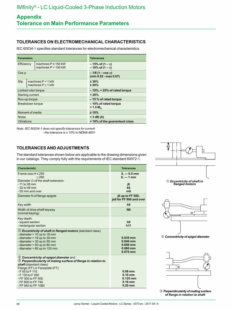
90 Leroy-Somer - Liquid-Cooled Motors - LC Series - 5370 en - 2017.05 / b
IMfinity® - LC Liquid-Cooled 3-Phase Induction Motors
Appendix
TOLERANCES ON ELECTROMECHANICAL CHARACTERISTICS IEC 60034-1 specifies standard tolerances for electromechanical characteristics.
Parameters Tolerances
Efficiency { machines P ≤ 150 kW machines P > 150 kW
– 15% of (1 – η)– 10% of (1 – η)
Cos j – 1/6 (1 – cos j)(min 0.02 - max 0.07)
Slip { machines P < 1 kW machines P ≥ 1 kW
± 30%± 20%
Locked rotor torque – 15%, + 25% of rated torqueStarting current + 20%Run-up torque – 15 % of rated torqueBreakdown torque – 10% of rated torque
> 1.5 MN
Moment of inertia ± 10%Noise + 3 dB (A)Vibrations + 10% of the guaranteed class
Note: IEC 60034-1 does not specify tolerances for current- the tolerance is ± 10% in NEMA-MG1
TOLERANCES AND ADJUSTMENTSThe standard tolerances shown below are applicable to the drawing dimensions given in our catalogs. They comply fully with the requirements of IEC standard 60072-1.
Characteristic Tolerances
Frame size H ≤ 250≥ 280
Diameter ∅ of the shaft extension:- 11 to 28 mm- 32 to 48 mm- 55 mm and over
0, — 0.5 mm0, — 1 mm
j6k6m6
Diameter N of flange spigots j6 up to FF 500,js6 for FF 600 and over
Key width h9Width of drive shaft keyway (normal keying)
N9
Key depth:- square section- rectangular section
h9h11
� Eccentricity of shaft in flanged motors (standard class)- diameter > 10 up to 18 mm- diameter > 18 up to 30 mm- diameter > 30 up to 50 mm- diameter > 50 up to 80 mm- diameter > 80 up to 120 mm
0.035 mm0.040 mm0.050 mm0.060 mm0.070 mm
� Concentricity of spigot diameter and� Perpendicularity of mating surface of flange in relation to shaft (standard class)Flange (FF) or Faceplate (FT):- F 55 to F 115- F 130 to F 265- FF 300 to FF 500- FF 600 to FF 740- FF 940 to FF 1080
0.08 mm0.10 mm
0.125 mm0.16 mm0.20 mm
E/2
10
10
E/2
10
10
� Eccentricity of shaft in flanged motors
� Concentricity of spigot diameter
� Perpendicularity of mating surface of flange in relation to shaft
Tolerance on Main Performance Parameters
91Leroy-Somer - Liquid-Cooled Motors - LC Series - 5370 en - 2017.05 / b
IMfinity® - LC Liquid-Cooled 3-Phase Induction Motors
Appendix
The Leroy-Somer configurator can be used to choose the most suitable motor and provides the technical specifications and corresponding drawings.
To register online:http://www.emersonindustrial.com/fr-FR/leroy-somer-motors-dr ives/Products/Configurator/
• Help with product selection• Print-outs of technical specifications• Print-outs of 2D and 3D CAD files• The equivalent of 400 catalogs in
16 languages
Configurator
5370 en - 2017.05 / b
www.nidecautomation.com
Connect with us at:
twitter.com/Leroy_Somerfacebook.com/leroysomer.nidecyoutube.com/user/LeroySomerOfficieltheautomationengineer.com (blog)
Moteurs Leroy-Somer SAS. Headquarters: Bd Marcellin Leroy, CS 10015, 16915 Angoulême Cedex 9, France. Share Capital: 65 800 512 €, RCS Angoulême 338 567 258.