Embed Size (px)
Citation preview

LATCHUP IN CMOS TECHNOLOGY

THE KLUWER INTERNATIONAL SERIES IN ENGINEERING AND COMPUTER SCIENCE
VLSI, COMPUTER ARCHITECTURE AND DIGITAL SIGNAL PROCESSING
Consulting Editor
Jonathan Allen
Other books in the series:
Logic Minimization Algorithms jor VLSI Synthesis. R.K. Brayton, G.O. Hachtel, C.T. McMullen, and A.L. Sangiovanni-Vincentelli. ISBN 0-89838-164-9.
Computer-Aided Design and VLSI Device Development. K.M. Cham, S.-Y. Oh, o. Chin, and J.L. Moll. ISBN 0-89838-204-1.
Adaptive Filters: Structures, Algorithms, and Applications. M.L. Honig and O.G. Messerschmitt. ISBN 0-89838-163-0.
Introduction to VLSI Silicon Devices: Physics, Technology and Characterization. B. EI-Kareh and R.J. Bombard. ISBN 0-89838-210-6.

LATCHUPIN CMOS TECHNOLOGY
The Problem and Its Cure
by
Ronald R. Troutman IBM Corporation
SPRINGER SCIENCE+BUSINESS MEDIA, LLC

Libnry of Congress Cataloging-in-Publication Data
Troutman, Ronald R. Latchup in CMOS technology.
(The Kluwer international series in engineering and computer science. VLSI, computer architecture, and digital signal processing)
Bibliography: p. Includes index. 1. Metal oxide semiconductors, Complementary
Defects. 2. Metal oxide semiconductors, ComplementaryReliability. I. Title. II. Series. TK7871.99.M44T76 1986 621.3815'2 86-2925 ISBN 978-1-4419-5199-1 ISBN 978-1-4757-1887-4 (eBook) DOI 10.1007/978-1-4757-1887-4
Copyright © 1986 by Springer Science+Business Media New York Originally published by Kluwer Academic Publishers in 1986 Softcover reprint ofthe hardcover Ist edition 1986
AII rights reserved. No part of this publication may be reproduced, stored in a retrieval system, or transmitted in any form or by any means, mechanical, photocopying, recording, or otherwise, without written permission of the publisher, Springer Science+Business Media, LLC,

Dedication
To Gail, who picked up the slack in so many areas and provided substantial encouragement for, and able assistance in, writing and editing this book.
CONTENTS
List of Figures xi
Preface: Why a Book on Latchup? xv
Acknowledgements xix
Chapter 1. INTRODUCTION 1 1.1 CMOS: The Emerging VLSI Technology 1 1.2 Latchup Prevention: A Historical Perspective 3 1.3 Latchup in VLSI CMOS: A Continuing Concern 5
Chapter 2. LATCHUP OVERVIEW 7 2.1 Structural Origins and a Lumped Element Model 7 2.2 An Example: Latchup in a Floating N-well Structure 15
Chapter 3. PROBLEM DESCRIPTION 23 3.1 Blocking and Latched States 23 3.2 Conditions Necessary for Latchup 24 3.3 Triggering Modes 24
3.3.1 Output Node Overshoot/Undershoot 25 3.3.2 Input Node Overshoot/Undershoot 26 3.3.3 Avalanching N-well Junction 26 3.3.4 Punchthrough from N-well to External N-Type Diffusion 28 3.3.5 Punchthrough from Substrate to Internal P-Type
Diffusion 29 3.3.6 Parasitic Field Devices 30 3.3.7 Photocurrent 32 3.3.8 Avalanching Source/Drain Junctions 33 3.3.9 Displacement Current 33
3.4 Triggering Taxonomy 34 3.4.1 Type 1: External Initiation of First Bipolar 34 3.4.2 Type 2: Normal Bypass Current Initiation of Both Bipolars 34 3.4.3 Type 3: Degraded Bypass Current Initiation of
Both Bipolars 35 3.4.4 Latchup Sequence and Classification Summary 35
Chapter 4. LATCHUP MODELS AND ANALYSES 37 4.1 Antecedents of Latchup Models 38
4.1.1 Hook Collector Transistor 38 4.1.2 Semiconductor Controlled Rectifier (SCR) 40
4.2 Evolution of the PNPN Lumped Element Model 47 4.2.1 Resistive Elements 48 4.2.2 Parasitic Bipolar Behavior 49 4.2.3 Previous Latchup Criteria 51
4.3 Physical Analysis of Latchup: A New Direction 54 4.3.1 Semiconductor Current Relationships 55 4.3.2 Static Latchup Criterion: An Incorrect Choice 58

viii
4.3.3 Differential Latchup Criterion: A Matter of Stability 4.3.4 High Level Injection Effects
4.4 SAFE Space: A Rigorous Definition ofthe Blocking State 4.4.1 Symmetric PNPN Structure 4.4.2 Floating N-well Triode 4.4.3 Floating Substrate Triode 4.4 ... General Tetrode
4.5 Saturation Region Modeling: A New View 4.5.1 Current Equations 4.5.2 Differential Resistance 4.5.3 Holding Current 4.5.4 Holding Voltage
4.6 Illustration of Latchup: Type 2 Triggering 4.6.1 A Sample Analysis 4.6.2 A SAFE Space Map and Switching Current
4.7 Modifications to Lumped Element Model: A Useful Perspective 4.7.1 Transmission Line Model of Latchup 4.7.2 Transfer Resistance
4.8 Dynamic Latchup Effects 4.8.1 Sources of Time Dependence
4.9 Modeling and Analysis Review
Chapter 5. LATCHUP CHARACTERIZATION 5.1 Measuring Instruments
5.1.1 Curve Tracer 5.1.2 Parameter Analyzer
5.2 Two Terminal Characterization 5.2.1 Supply Overvoltage Stress 5.2.2 Supply Overcurrent Stress
5.3 Three and Four Terminal Characterization 5:3.1 Voltage Excitation at External Emitter or Base Terminal 5.3.2 Current Source Excitation on Bypass Resistor Terminal 5.3.3 Current Source Excitation on External Emitter Terminal
5.4 Switching Point Characterization 5.5 Holding Point Characterization 5.6 DynamicTriggering 5.7 Temperature Dependence 5.8 Non-Electrical Probing 5.9 Characterization Review
Chapter 6. AVOIDING LATCHUP 6.1 Layout Guidelines
6.1.1 Guard Structures 6.1.2 Multiple Well Contacts 6.1.3 Substrate Contact Ring 6.1.4 Butted Source Contacts
6.2 Process Techniques for Bipolar Spoiling 6.2.1 Lifetime Reduction 6.2.2 Retarding Base Field 6.2.3 Schottky Barrier Source/Drain
6.3 Process Techniques for Bipolar Decoupling 6.3.1 Epi-CMOS 6.3.2 Retrograde Well for Lower Sheet Resistance
Contents
59 63 66 67 69 71 72 76 77 80 81 83 84 84 90 93 94 99
104 105 115
117 118 118 124 126 126 129 130 131 133 135 138 149 155 160 161 163
165 165 165 172 172 173 174 174 175 178 181 181 184

Contents
6.3.3 Substrate and Well Bias 6.3.4 Trench Isolation
6.4 CMOS Design Considerations 6.5 Latchup-free Design
6.5.1 Decouple Vertical Parasitic (DVP) 6.5.2 Decouple Lateral Parasitic (DLP)
Chapter 7. SUMMARY 7.1 Problem Description 7.2 Modeling and Analysis 7.3 Characterization 7.4 Avoiding Latchup
Appendices A. Stability Considerations for PNPN Current-Voltage
Measurements B. Possible Latchup Characterization Problems
References
Glossary: Symbol Definitions
Index
About the Author
ix
185 188 190 192 193 196
197 197 198 201 204
209 213
217
227
239
243

Figures
Chapter 2. LATCHUP OVERVIEW 2-1. Cross section of inverter circuit in N-well CMOS 8 2-2. Parasitic bipolar portion of N-well CMOS inverter 9 2-3. Complete circuit schematic for N-well CMOS inverter 11 2-4. illustrative PNPN current/voltage characteristics 12 2-5. Emitter/base bypass resistances for N-well CMOS inverter 13 2-6. Parasitic bipolar portion of 4-terminal PNPN structure 14 2-7. Lumped element model for distributed N-well collection 15 2-8. Lumped element model for PNPN structure with a floating
N-well 16 2-9. Latchup criterion for PNPN structure with floating N-well 18 2-10. Transistor parameters for simulations of Figs. 2-11 and 2-12 19 2-11. Characteristics of floating well in latched state 20 2-12. PN junction biases in latched state 21
Chapter 3. PROBLEM DESCRIPTION 3-1. Current path across collector/base junction 21 3-2. N-well avalanche triggering of latchup 21 3-3. Current path from collector to emitter 28 3-4. Punchthrough triggering of latchup 29 3-5. Field PET triggering of latchup 31 3-6. Triggering taxonomy and latchup sequence 36
Chapter 4. LATCHUP MODELS AND ANALYSES 4-1. Point-contact transistor 39 4-2. Experimental V /1 characteristics for SCR triode 43 4-3. Lumped element model for 4-terminal PNPN structure 47 4-4. External connections for 4-terminal PNPN device 55 4-5. SAFE space representation of the blocking state 66 4-6. illustration of general tetrode latchup condition 73 4-7. Parameter values for lumped element model 85 4-8. PNPN turn-on characteristics in the blocking state 86 4-9. Comparison of static and differentiallatchup criteria 87 4-10. Saturation I!V characteristics for a PNPN structure 88 4-11. PNPN saturation bypass and emitter currents vs. terminal
current 89 4-12. PNPN differential resistance vs. terminal current 90

xii Latchup in CMOS
4-13. A representative map of SAFE space 91 4-14. A comparison of triode and tetrode switching currents 92 4-15. Cross section of parasitic PNPN structure 95 4-16. Transmission line model for parasitic PNPN structure 96 4-17. Transfer resistance definitions 97 4-18. Dependent voltage source model of latchup 98 4-19. Output-excited transfer resistance for high output
resistance 99 4-20. Output-excited transfer resistance for low output
resistance 101 4-21. Input-excited transfer resistance vs. section lengths 102 4-22. Substrate majority carrier guard structure 103 4-23. Comparison of turn-on time for high and low level
injection 106 4-24. Simulated PNPN response to ramped power supply 108 4-25. Blocking state potential distribution 109 4-26. Transient potential distribution 110 4-27. Latched state potential distribution 111 4-28. Electron and hole currents vs. time in nS 112 4-29. Instantaneous behavior 2.9 nS after pulsing LPNP base 113 4-30. Instantaneous behavior 3.4 nS after pulsing LPNP base 114
Chapter 5. LATCHUP CHARACTERIZATION 5-1. Curve tracer characterization of latchup 119 5-2. Supply overvoltage triggered characteristics 121 5-3. Curve tracer latchup characteristics 122 5-4. Blocking state characterization 125 5-5. Supply overvoltage stress condition 127 5-6. Supply overvoltage latchup characteristics 129 5-7. P-well current triggering 134 5-8. Switching from the blocking state 136 5-9. Points of zero differential resistance 137 5-10. illustration of 1 mV measurement resolution 139 5-11. Small-signal alpha and beta 141 5-12. Determination of internal substrate resistance 142 5-13. Switching current for PNP-driven triode configuration 143 5-14. Second transistor emitter current at switching point 144 5-15. Determination of internal N-well resistance 145 5-16. Switching current for NPN-driven triode configuration 146 5-17. Second transistor emitter current at the switching point 147 5-18. Comparison of lateral, small-signal betas 148 5-19. Latched state I!V characteristics 150 5-20. Holding point measurement using voltage source 152 5-21. Low impedance state currents 154 5-22. Transient excitation using power supply ramp 155

Figures
5-23. Critical power supply risetime 5-24. Transient excitation by base injection 5-25. P-well pulse excitation 5-26. Emitter/base pulse excitation
Chapter 6. A VOIDING LATCHUP 6-1. Minority carrier guard in substrate 6-2. P-well PNPN structure 6-3. Majority carrier guard in well 6-4. Majority carrier guard in substrate 6-5. Schottky barrier source/drain fabrication 6-6. Substrate generator with 2-stage charge pump 6-7. Charge pump waveforms 6-8. Various lateral isolation technologies 6-9. Worst case latchup consequences
APPENDICES
xiii
156 157 158 159
168 169 170 171 178 186 187 189 196
A-I. Circuit schematic for current excitation of PNPN device 210 A-2. Dlustration of negative differential resistance measurements 211 B-1. Substrate potential at the switching point 214

Preface
Why a book on Iatchup?
Latchup has been, and continues to be, a potentially serious CMOS reliability concern. This concern is becoming more widespread with the ascendency of CMOS as the dominant VLSI technology, particularly as parasitic bipolar characteristics continue to improve at ever smaller dimensions on silicon wafers with ever lower defect densities. Although many successful parts have been marketed, latchup solutions have often been ad hoc. Although latchup avoidance techniques have been previously itemized, there has been little quantitative evaluation of prior latchup fixes. What is needed is a more general, more systematic treatment of the latchup problem. Because of the wide variety of CMOS technologies and the long term interest in latchup, some overall guiding principles are needed.
Appreciating the variety of possible triggering mechanisms is key to a real understanding of latchup. This work reviews the origin of each and its effect on the parasitic structure. Each triggering mechanism is classified according to a new taxonomy. In Type 1 triggering one of the parasitic bipolars has been turned on by an external source, and if its collector current is large enough, it turns on the second. In Type 2 triggering the external source causes current to flow through both bypass resistors. If large enough, the bypass current turns on the first transistor, whose collector current then supplements the bypass current in turning on the second. In Type 3 triggering the external source has degraded the blocking state by creating a low impedance path even before the parasitic bipolars are turned on. This taxonomy helps systematize latchup modeling and characterization.
Latchup models in the technical literature are not well developed, and there is little agreement on a specific, yet widely
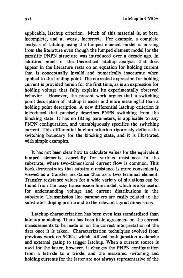
xvi Latchup in CMOS
applicable, latchup criterion. Much of this material is, at best, incomplete, and at worst, incorrect. For example, a complete analysis of latchup using the lumped element model is missing from the literature even though the lumped element model for the parasitic PNPN structure was introduced over a decade ago. In addition, much of the theoretical latchup analysis that does appear in the literature rests on an equation for holding current that is conceptually invalid and numerically inaccurate when applied to the holding point. The corrected expression for holding current is provided herein for the first time, as is an expression for holding voltage that fully explains its experimentally observed behavior. However, the present work argues that a switching point description of latchup is easier and more meaningful than a holding point description. A new differential latchup criterion is introduced that precisely describes PNPN switching from the blocking state. It has no fitting parameters, is applicable to any PNPN configuration, and unambiguously specifies the switching current. This differential latchup criterion rigorously defines the switching boundary for the blocking state, and it is illustrated with simple examples.
It has not been clear how to calculate values for the equivalent lumped elements, especially for various resistances in the substrate, where two-dimensional current flow is common. This book demonstrates that substrate resistance is more conveniently viewed as a transfer resistance. than as a two terminal element. Transfer resistance values for a wide variety of situations can be found from the lossy transmission line model, which is also useful for understanding voltage and current distributions in the substrate. Transmission line parameters are easily related to the substrate's doping profile and to the relevant layout dimensions.
Latchup characterization has been even less standardized than latchup modeling. There has been little agreement on the correct measurements to be made or on the correct interpretation of the data once it is taken. Characterization techniques evolved from previous work on SCR's, which utilized both junction avalanche and external gating to trigger latchup. When a current source is used for the latter, however, it changes the PNPN configuration from a tetrode to a triode, and the measured switching and holding currents for the latter are not always representative of the

Why a book on latchup? xvii
former. The switching current can be measured unambiguously for the tetrode using a parameter analyzer with a current source on one of the emitters. Measurements made this way agree very closely with the new differentiallatchup criterion.
Because the parasitic bipolars in the PNPN structure each have a finite response time, switching from the blocking state requires a stronger excitation when that excitation is applied for only a short duration. Understanding this behavior is important for quantitatively describing triggering conditions encountered during actual operation. The key is knowing whether the transient excitation can shift the dynamic operating point to the switching border of SAFE space.
Latchup is avoided by operating CMOS circuits solely in SAFE space. This strategy can be implemented using layout guidelines, processing techniques, or some combination of both. Previous implementations are critiqued from a fresh perspective that enables the designer to judge their applicability. Guard structures are explained, and their various forms are compared.
Processing techniques prevent latchup by either spoiling the parasitic bipolar characteristics or decoupling the parasitic NPN and PNP from one another. Although both have met with some success, the latter is more compatible with today's CMOS technologies and has been more widely implemented. Specific decoupling recommendations are made and discussed relative to general CMOS design considerations.
If proper attention is given to these process and layout guidelines, CMOS will be free of latchup, even for micron and sub-micron lithography. This book discusses how these guidelines can be used to restrict all parasitic PNPN devices to SAFE space.

Acknowledgements
Many people have contributed to the writing of this book through their papers and presentations on latchup. I have carefully referenced specific contributions from the technical literature throughout the pages, but the bibliography is not intended to be totally exhaustive (and hopefully not totally exhausting). I have enjoyed many valuable and stimulating discussions with colleagues working to eliminate the latchup problem, and their generosity in providing information has improved the quality of this work. Of the many I would like to specifically cite H. Zappe and I. Leventhal, whose theses have enhanced the latchup literature, as well as W. Craig, M. Hargrove, G. Hu, W. Lynch, D. Nelsen, A. Ochoa, R. Rung, and C. Sodini.
Thanks also goes to P. Chatterjee for an invitation to review recent latchup developments at the 1983 Device Research Conference. Preparing this talk planted the seed for the present monograph. Its growth was nourished by material originally prepared for several latchup seminars given in 1984 and, at the invitation of Prof. Viswanathan and J. Chen, for a UCLA short course given in June of that year and again in Jan. 1985. An encapsulated review of this material was presented at the 1984 IEDM, thanks to R. Davies' invitation.
I am also very grateful to the mM Corporation in general, and to W. T. Siegle and my manager J. Hiltebeitel in particular, for making possible a year's sabbatical at MIT during which the major portion of this monograph came to fruition. A special note of thanks is due C. Tillman and R. Reynolds of the mM Cambridge Scientific Center for their patient and able assistance in using QPRINT and transferring data files. Thanks also go to B. EI-Kareh and R. Bombard for timely advice and assistance in the final preparation of this book.

LATCHUP IN CMOS TECHNOLOGY