Embed Size (px)
Citation preview
Class D16/1a Engineering
and design overview

Red Diamond Diesel Construction - D16/1a engineering and design overview Page 3 of 16
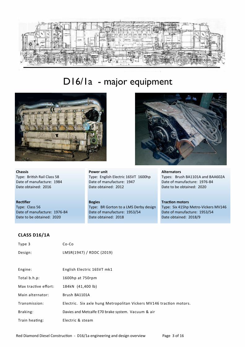
D16/1a - major equipment…
Chassis Type: British Rail Class 58 Date of manufacture: 1984 Date obtained: 2016 Rectifier Type: Class 56 Date of manufacture: 1976-84 Date to be obtained: 2020
Power unit Type: English Electric 16SVT 1600hp Date of manufacture: 1947 Date obtained: 2012 Bogies Type: BR Gorton to a LMS Derby design Date of manufacture: 1953/54 Date obtained: 2018
Alternators Types: Brush BA1101A and BAA602A Date of manufacture: 1976-84 Date to be obtained: 2020 Traction motors Type: Six 415hp Metro-Vickers MV146 Date of manufacture: 1953/54 Date obtained: 2018/9
CLASS D16/1A
Type 3 Co-Co
Design: LMSR(1947) / RDDC (2019)
Engine: English Electric 16SVT mk1
Total b.h.p: 1600hp at 750rpm
Max tractive effort: 184kN (41,400 lb)
Main alternator: Brush BA1101A
Transmission: Electric. Six axle hung Metropolitan Vickers MV146 traction motors.
Braking: Davies and Metcalfe E70 brake system. Vacuum & air
Train heating: Electric & steam
INTRODUCTION
This document is intended to give an overview of the
planned design of our loco, the third Class 16/1 loco,
which will be known as LMS 10000.
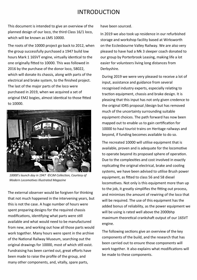
The roots of the 10000 project go back to 2012, when
the group successfully purchased a 1947 build low
hours Mark 1 16SVT engine, virtually identical to the
one originally fitted to 10000. This was followed in
2016 by the purchase of the donor loco, 58022,
which will donate its chassis, along with parts of the
electrical and brake system, to the finished project.
The last of the major parts of the loco were
purchased in 2019, when we acquired a set of
original EM2 bogies, almost identical to those fitted
to 10000.
The external observer would be forgiven for thinking
that not much happened in the intervening years, but
this is not the case. A huge number of hours were
spent preparing designs for the required chassis
modifications, identifying what parts were still
available and what would need to be manufactured
from new, and working out how all those parts would
work together. Many hours were spent in the archive
of the National Railway Museum, searching out the
original drawings for 10000, most of which still exist.
Fundraising has been carried out, great efforts have
been made to raise the profile of the group, and
many other components, and, vitally, spare parts,
have been sourced.
In 2019 we also took up residence in our refurbished
storage and workshop facility based at Wirksworth
on the Ecclesbourne Valley Railway. We are also very
pleased to have had a Mk 3 sleeper coach donated to
our group by Porterbrook Leasing, making life a lot
easier for volunteers living long distances from
Derbyshire.
During 2019 we were very pleased to receive a lot of
input, assistance and guidance from several
recognised industry experts, especially relating to
traction equipment, chassis and brake design. It is
pleasing that this input has not only given credence to
the original IDRS proposal /design but has removed
much of the uncertainty surrounding suitable
equipment choices. The path forward has now been
mapped out to enable us to gain certification for
10000 to haul tourist trains on Heritage railways and
beyond, if funding becomes available to do so.
The recreated 10000 will utilise equipment that is
available, proven and is adequate for the locomotive
to operate beyond its proposed sphere of operation.
Due to the complexities and cost involved in exactly
replicating the original electrical, brake and cooling
systems, we have been advised to utilise Brush power
equipment, as fitted to class 56 and 58 diesel
locomotives. Not only is this equipment more than up
to the job, it greatly simplifies the fitting out process,
and minimises the amount of rewiring of the loco that
will be required. The use of this equipment has the
added bonus of reliability, as the power equipment we
will be using is rated well above the 2000bhp
maximum theoretical crankshaft output of our 16SVT
engine.
The following sections give an overview of the key
components of the build, and the research that has
been carried out to ensure those components will
work together. It also explains what modifications will
be made to these components.
10000’s launch day in 1947 ©CJM Collection, Courtesy of
Modern Locomotives Illustrated Magazine
Red Diamond Diesel Construction - D16/1a engineering and design overview Page 5 of 16
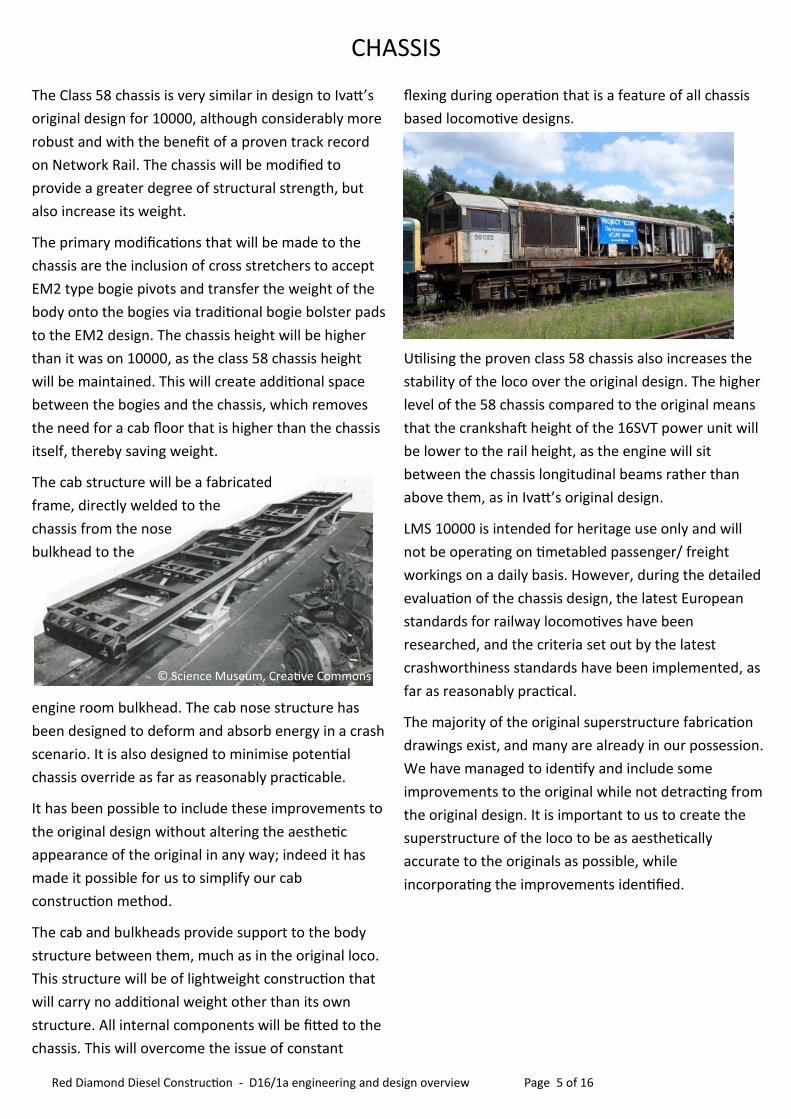
The Class 58 chassis is very similar in design to Ivatt’s
original design for 10000, although considerably more
robust and with the benefit of a proven track record
on Network Rail. The chassis will be modified to
provide a greater degree of structural strength, but
also increase its weight.
The primary modifications that will be made to the
chassis are the inclusion of cross stretchers to accept
EM2 type bogie pivots and transfer the weight of the
body onto the bogies via traditional bogie bolster pads
to the EM2 design. The chassis height will be higher
than it was on 10000, as the class 58 chassis height
will be maintained. This will create additional space
between the bogies and the chassis, which removes
the need for a cab floor that is higher than the chassis
itself, thereby saving weight.
The cab structure will be a fabricated
frame, directly welded to the
chassis from the nose
bulkhead to the
engine room bulkhead. The cab nose structure has
been designed to deform and absorb energy in a crash
scenario. It is also designed to minimise potential
chassis override as far as reasonably practicable.
It has been possible to include these improvements to
the original design without altering the aesthetic
appearance of the original in any way; indeed it has
made it possible for us to simplify our cab
construction method.
The cab and bulkheads provide support to the body
structure between them, much as in the original loco.
This structure will be of lightweight construction that
will carry no additional weight other than its own
structure. All internal components will be fitted to the
chassis. This will overcome the issue of constant
flexing during operation that is a feature of all chassis
based locomotive designs.
Utilising the proven class 58 chassis also increases the
stability of the loco over the original design. The higher
level of the 58 chassis compared to the original means
that the crankshaft height of the 16SVT power unit will
be lower to the rail height, as the engine will sit
between the chassis longitudinal beams rather than
above them, as in Ivatt’s original design.
LMS 10000 is intended for heritage use only and will
not be operating on timetabled passenger/ freight
workings on a daily basis. However, during the detailed
evaluation of the chassis design, the latest European
standards for railway locomotives have been
researched, and the criteria set out by the latest
crashworthiness standards have been implemented, as
far as reasonably practical.
The majority of the original superstructure fabrication
drawings exist, and many are already in our possession.
We have managed to identify and include some
improvements to the original while not detracting from
the original design. It is important to us to create the
superstructure of the loco to be as aesthetically
accurate to the originals as possible, while
incorporating the improvements identified.
CHASSIS
© Science Museum, Creative Commons

A set of original EM2 bogies, built in 1951, have been
purchased for use on 10000, as they are virtually
identical to the original D16/1 bogies. The bogies
have been stored outdoors for a number of years and
will require a complete overhaul. The bogies and
traction motors will be completely stripped and
assessed before being shot blasted and painted.
Although no fractures have been found or are
expected, both bogies will also undergo crack
detection during the cleaning and painting process.
Appropriate cosmetic alterations will be made to
ensure the bogies are a close visual match to the
originals.
The refurbishment of the bogies and the decision as
to which motors and wheelsets should be used has
been the subject of much discussion. After
consultation with various industry experts, the most
appropriate solution has now been identified.
Our original proposal was to re-engineer the bogies
with traction motors of English Electric lineage; the
EE538 as used in Class 37. However to fit these
motors to the EM2 wheelsets would require them to
be fully stripped and re-machined. This carried the
risk of rendering one or more axles as scrap if a
wheelpan “picked up” upon removal - an entirely
possible scenario with interference fits as tight as 7
thousands of an inch. This proposal would also have
been extremely costly to carry out. What it would
also do is change the proven EM2 bogie design, which
would bring an additional set of problems.
The EM2 bogies purchased are fitted with
Metropolitan Vickers MV146 motors, which are similar
in design to the EE 519/1B traction motors originally
fitted to 10000 but more powerful. It was found that
these motors would be suitable and would be able to
be connected to the Brush electrical package without
difficulty. With this course of action now decided, we
have secured budget estimates for the assessment and
repair of the Metropolitan Vickers motors. The use of
these motors will allow us to utilise all the existing
associated parts and removes the need to re-engineer
and modify a design that is already proven to work well
and is and is fit for future use.
One of our main concerns when deciding which type of
motor to use was the difficulty in obtaining additional
spare / replacement MV146 motors should one of
those in the EM2 bogies suffer a catastrophic failure.
We have been very fortunate in locating some spare
MV146 motors in Holland, owned by Werkgroep 1501,
who have an EM2 loco in their care. We are very
grateful to the group for allowing us to purchase these
motors, which have been dry stored, and will need
minimal refurbishment before they can be fitted to
one of our refurbished bogies. Werkgroep 1501 have
also agreed to supply us with several pallets of EM2
bogie and brake spares, which will considerably speed
up the bogie refurbishment process.
The bogies will be overhauled and rebuilt to the
relevant British Rail Workshop Overhaul Specification
Standard that will enable us to achieve mainline
registration. This will allow 10000 to access the
network dead in tow to enable it to visit locations far
and wide.
BOGIES AND TRACTION MOTORS
© Science Museum, Creative Commons

Red Diamond Diesel Construction - D16/1a engineering and design overview Page 7 of 16
BRAKING SYSTEM
As part of our evaluation of potential options for
wheelsets, motors, bearings and gears, we also looked
at how we would stop the loco efficiently. The original
locos provided vacuum braking to both the locomotive
and train. To replicate the brakes as original would be
an expensive and challenging task. It also would render
the loco unable to haul air braked stock. We have
considered many options, including fitting the class 58
direct acting brake pistons that would minimise the
amount of brake rigging that would be required.
However, this option brings with it other difficulties,
and we have been advised to utilise an already proven
method of braking these bogies; the standard EM2 air
braking system and its very clever mechanical acting
handbrake mechanism.
The use of the EE 16SVT engine will require the removal
of the flawed class 58 brake compressors and
associated equipment. The removal of this belt driven
system takes a lot of unnecessary weight and bulk from
the chassis. In its place will be a standard BR Davies and
Metcalfe brake compressor as used on classes 43 and
56, and equipment contained within the brake cubicle.
The train vacuum braking system will be Westinghouse
equipment, as fitted to class 37, similar to the
equipment fitted to the original locomotives. This will
be controlled from the Davies and Metcalfe electrical
controls.
Experience has taught us that the Davies and Metcalfe
E70 brake system as fitted in various guises to class 43,
56, 89, 90 and 91 has stood the test of time, being a
very reliable and widely accepted system. The decision
to use the E70 system on 10000 has been made based
on this known reliability, and the currently plentiful
supply of spares.
The removal of the original air compressor and
associated equipment creates a change to the original
class 58 layout. With 10000 being a full width
locomotive, we have been able to create additional
space to enable us to have full 360 degree access to the
brake cubicle. The two main air receivers within the
loco will be relocated to the nose ends, freeing up space
for the standard air compressors within the brake
cubicle, which will allow good access for maintenance.
The Westinghouse vacuum exhausters will be located
between the cooler group and the cab, in the area
made vacant by the reduction in size of the class 58
cooler group. This area is where the fuel tank was
located in the original loco. Space has been deliberately
left in this area, which gives us flexibility and
adaptability during the build process. It would be
possible in the future, for example, to utilise this space
for additional fuel capacity should the need ever arise.

We have been very lucky in acquiring an original 1947
Mk1 16SVT English Electric engine with very low
hours. This engine, vital to the project, is currently in
secure storage, protected from the weather.
We are also in contact with the MOD regarding an
identical engine which was previously used as a
standby power generator. This engine also has very
low hours of use. The possession of a spare engine
will give us great resilience against any future engine
issues that may be encountered.
During inspections of our class 58 loco, it became
apparent that the air compressor previously
mentioned sits on a heavy frame at the back of the
12 cylinder engine, effectively occupying the place
where the rear two pistons of the 16SVT will be.
The engine will be mounted in the location where the
alternator currently resides. The free end of the
engine will have to be mounted on the frame further
back, which will necessitate the relocating of the
current engine bearer stretcher to align with the rear
engine mountings on the 16SVT. It is convenient for
our design process that our 16 cylinder non charge
cooled engine is actually a similar weight to the 12
cylinder Ruston utilised within the 58, due its large
turbocharger, intercoolers, heat exchangers and a
very large exhaust silencer.
For our 16SVTs to operate with the Brush electrical
equipment our engines will require modified class 56
governors that will be bespoke to our project.
A supplier able to provide this service has been
identified and discussions are underway regarding
the design.
Some minor adaptations for rail use will be required.
The current air start system will be removed, and the
injectors will be exchanged for class 20 parts. The fuel
pumps may also be required to be exchanged for
class 20 items, but this has not yet been confirmed.
We will require derogation for our 16SVT power
plant. The 16SVT has proven itself to be a very clean
engine when up to operating temperature and set up
correctly, but it has never been Euro 3A compliant
and without a great deal of modification it can be
reasonably assumed that it never will be. The
argument could be made that the 16SVT is more
environmentally sound than the equivalent Paxman
16 and 12 cylinder engines used in the class 56 or the
58 and will also use much less fuel.
ENGINE

Red Diamond Diesel Construction - D16/1a engineering and design overview Page 9 of 16
Traction Motor blowers and ducting
The traction motor blowers on 10000 and 10001, and
several other designs up to the early 1960’s, were
located in the nose ends, and directed air through a
lightweight ducting to each motor position.
The motors were then connected to the duct with a
flexible bellow.
The class 58 does not have the benefit of nose ends
to house the blowers, and instead both sit close to
the engine room; one in the cooler group and one in
the auxiliaries compartment. This presents a
challenge in that we need to maintain a corridor
access through the loco without obstruction, which is
not necessary on the class 58 loco. To add to this
issue, the traction motors in the EM2 bogies are of a
different orientation, meaning that the class 58
ducting ports are in the wrong places for our bogies.
Two solutions have been employed to overcome
these problems. The blower within the auxiliaries
compartment will be rotated by 90 degrees.
The blower in the cooler group remain in its existing
location. On examining the existing traction motor
ducting outputs, it can be clearly seen that it is
possible to remove them and move them to the ideal
locations, plating over the holes where they were
originally located.
ELECTRICAL EQUIPMENT
The Brush BA1101 alternator utilised on the class
56/58 is of similar dimensions of the EE823A as used
in the original. As the original 16SVT and the Paxman
fitted to the 56 are basically the same engine, albeit
with considerable development and improvement,
the fitment of the alternator to the engine will be
straight forward.
For convenience, the electrical equipment cubicle will
remain in its existing location, although it will contain
mainly class 56 equipment, that has minor
differences but much better spares availability than
the class 58 equipment. Some alterations will be
necessary, especially to the various control modules,
to give 10000 the maximum potential capability from
its much lower maximum engine output. A specialist
contractor has been identified who is able to carry
out this work. The benefit of 10000 being a full width
loco compared to the 58 means that there will be
plenty of space around the cubicle, which will give
adequate access for development of systems and
maintenance.
We are in discussions to obtain a number of ex class
56 items, including two complete electrical cubicles,
cooler groups and power units including alternators.
This will be a great boost to the project, due to the
similarities of the 56 electrical and cooling
components to the class 58 we currently own. It will
also provide us with a significant source of spare parts, increasing our resilience to any future equipment
failures.

As mentioned above, due to our maximum attainable
horse power being significantly lower than the class 58
loco, we will not require its full cooling capacity, and
consequently the cooler group will be reduced in size
to both reduce weight and replicate more closely the
aesthetic appearance of the original Serck radiators
fitted to 10000. An issue that affected the original
locos throughout their life is that their cooling system
was only just up to the job, with the D16/1
locomotives regularly running hot in service. Although
it will be reduced in size, the increased capacity of the
class 58 cooling system allows us the opportunity to
finally resolve this issue.
COOLING
CAB DESIGN AND EQUIPMENT
We aim to replicate the original cab interior as far as
is possible. The design of the cab structure has been
completed, and CAD drawings completed of all
components. The practicality of the construction has
been discussed with steel fabrication contractors, and
the construction of the cabs has been fully costed.
The cab will have a steel structure which has been
designed in a similar way to the original, but with
added structural integrity for protection of the
occupants should the worst happen. In addition, all
windows will conform to current industry standards.
The controls will be tried, tested and certified and
calibrated class 56 equipment, disguised to maintain
the appearance of the original. The driver’s desk and
controls will be designed to be easier to remove for
maintenance purposes. The cab will function in much
the same way as it did in 1947, with access to the
nose end doors, air operated wipers, period levers
and switches retaining the 1947 image and feel.
Inside the nose end, unlike the original, the loco will
not have traction motor blowers, as these are located
elsewhere in the class 58, and there is no significant
benefit in relocating them. This important and useful
area will instead be used for air receivers, the
handbrake mechanism and access to the cab control
equipment. The nose areas will also contain equipment
storage areas with a locker included in each nose.
If mainline running were to become a reality these
areas would be the ideal location for the required loco
safety systems, and with this in mind the nose ends will
be wired to make this possible.
Red Diamond Diesel Construction - D16/1a engineering and design overview Page 11 of 16
TRAIN HEATING
One of the few significant failings of the D16/1 locos
was the train heating system. As built, they were fitted
with a Clarkson boiler that was found to be unreliable
in service. Our President Stan Fletcher, who was one of
the commissioning engineers in 1947 reports that the
Clarkson boiler would often shut down during a
journey, necessitating repetitive re-lighting with mixed
success. The problems were never resolved, and the
boiler was replaced with a Spanner Mk1. This increased
the locos weight by three imperial tons, and although it
was an improvement, the boiler still proved to be
problematic and unreliable.
It is our aim to fit 10000 with steam heating; however
this is not without its issues. As with steam heating
systems of the time, a modern equivalent will weigh
several tonnes in fully working order and take up a lot
of room within the loco. To fit steam heat may require
the relocation of the brake cubical and the electric
cubical which will be a complex and expensive task to
complete.
It is also planned to fit 10000 with electric train heating,
to increase the flexibility of the loco and allow it to
operate with more types of stock. The auxiliary
alternator that we will be using is capable of far more
than the efficient operation of the loco systems, indeed
they have been proven to supply an ETH index of 100
on the class 57/3. This equates to around 700hp power
consumption which would supply a long air conditioned
train. With this type of capacity we do have the ability
to fit a system that can heat any heritage railway train,
either pulling a rake of mk1 coaching stock or heating a
longer rake of mk3 coaching stock with an additional
loco for extra traction. As the original loco was not
fitter with ETH, the cable will be hidden behind the
nose end doors, to maintain the authentic 1947 nose
end profile.
It is our aim to make the loco as flexible and useable as
possible, to increase the potential for its use, especially
throughout the winter season. However, there are
some complex issues to overcome, and this is an area
that is still under development and review.
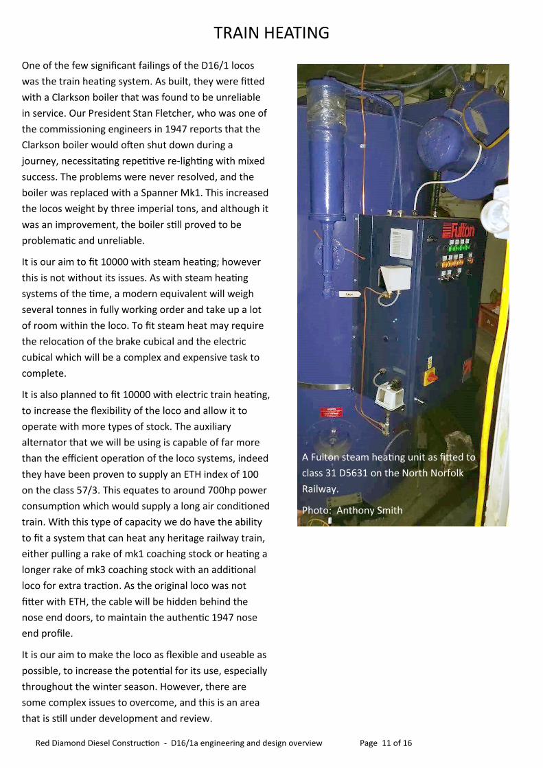
A Fulton steam heating unit as fitted to
class 31 D5631 on the North Norfolk
Railway.
Photo: Anthony Smith

FUEL AND UNDERSLUNG EQUIPMENT
Underneath a class 58 there is a lot of weight
suspended between the bogies. All this equipment,
including the fuel tank, will be removed.
The air receivers will be relocated to the nose end
compartments. The battery boxes will be modified to
the dimensions and appearance of the originals. As
mentioned earlier, the expected use of the loco will
be in a heritage railway setting, and as such the
current large fuel capacity will not be a requirement.
A new, significantly smaller fuel tank will be
fabricated, that will sit between the battery boxes
lowering down towards the centre of the locomotive.
This will give 10000 sufficient range and will ensure
that we can maintain a clean fuel system by not
having too large a fuel system. The tank will be of a
robust construction, and manufactured to modern
safety standards.
BUILD PROCESS
Utilising the class 58 loco for the chassis of 10000
keeps the loco very close to the basic design of the
class 58, which has been used all over Europe and is
a fully proven design. However, there will be some
modifications required to turn back the clock over
70 years, which will require a “derogation process”
to be adopted and examined by Competent
Selected Persons.
Now that our design process for the use of the
bogies has been completed, we have effectively
created a new locomotive design based on three
previous proven designs - Class 58, class 77 (EM2)
and 16/1, the original 10000 and 10001. So, we have
achieved derogation to an extent already, with the
chassis re- design of the bogie pivot method and
weight transfer of the loco body onto the bogies.
These modifications will be designed and analysed
by Selected Persons to be suitable and sufficient
over three criteria; longitudinally, laterally and
vertically. Their modification and fitment will be
done to an agreed and exacting procedures and
standards that are fully documented. All welding will
be done by certified and competent persons, and
also fully documented to the required quality
assurance standards.
Our intention to build and maintain the loco to a
high level and to a well-documented standard will
ensure that the finished loco is fully fit for purpose
and is as safe to operate on a rail system both light
rail and mainline as any other rail vehicle.
Photos: ©CJM Collection, Courtesy of
Modern Locomotives Illustrated Magazine
Red Diamond Diesel Construction - D16/1a engineering and design overview Page 13 of 16
LMS 10000 has been designed to be a very capable
machine. It utilises traction equipment that is
capable of much more power than we can feed it
with, and retains the reliability of the very lightly
stressed engine which was designed to generate
1600hp continually for many hours.
Due to the robust nature of the power equipment it
will be possible to make use of the full power of the
loco at a low track speed. When put together with
the traditional EM2 bogies, the loco will be capable
of lifting very heavy trains on steeply graded track
without overheating its electrical equipment. The
loco will have a theoretical top attainable speed with
a 300 tonne train of 80mph with one stage of field
weakening taking place at around 45mph. The
engine is capable of generating around 1800hp at
750rpm with careful tuning and development. It is
however possible to run the power unit safely at
850rpm, which would increase its output to just
below type 4 power classification.
In real terms this type of rating with this equipment
used will create a diesel electric locomotive very
similar in performance and characteristics as a class
57/0 diesel electric. Locomotive tractive effort is
expected to be dramatically increased over the
original D16/1 design, as is its overall suitability and
reliability as a railway vehicle in its own right.
However the important factor is, it will operate, look
and sound just like it did in 1947.
With railway industry help it has been confirmed that
building our locomotive to this design and utilizing the
correct method of design and approval is the most
fundamentally sound way of recreating 10000. The
design decisions that we have made will ensure
operational compatibility and spares availability for
many years to come. We will have created the ideal
locomotive for heritage line use that can be enjoyed
by all, while also telling the story of diesel locomotive
evolution within the UK.
PROJECTED LOCOMOTIVE PERFORMANCE
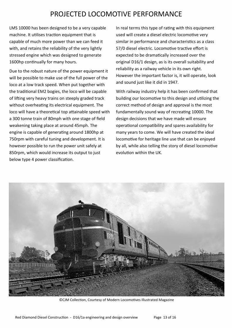
©CJM Collection, Courtesy of Modern Locomotives Illustrated Magazine
To recreate any pre-existing railway vehicle is an
expensive and very time consuming undertaking.
Due to the historical importance of 10000 and 10001
which undoubtedly set the benchmark in all its
design and equipment features to every diesel
electric locomotive built since in the UK, the design
detailed within this document is the most, accurate,
cost effective way to achieve our goal. We have been
able to utilise what was learnt over thirty years of
loco design it and eradicate most of the
shortcomings of the design itself.
As a prototype, the locos were not without their
issues and faults. However although they were the
first of their kind in the UK, they were very
successful, and much was learned over the hundreds
of thousands of miles they both operated. We have
also managed to eradicate the main shortcomings of
the class 58 design. The very problematic air brake
compressors will be removed, as will the Ruston
engine that BR at one point considered exchanging
for a Sulzer 12AS due to the Ruston’s poor cold
starting, and the habit of pistons and blocks to crack
at its original power rating of 3300hp. The bogies
that would have been better suited to medium/high
speed use instead of slow speed use on poorly laid
trackwork that was slippery at the best of times have
also gone, exchanged for proven bogies, built to a
more traditional design that will be more suitable
and sufficient for heritage train use.
In addition to these points, we have saved ourselves a
lot of time, effort, money and materials by re-using pre
designed and proven brake pipe designs, miles of
electrical cables, yards of electrical conduit, approved
fire protection systems, and fully proven traction
systems.
How ironic it is that the first built British Railways
diesel electric locomotive 10001, was to be so similar
in design and layout to the last diesel electric
locomotive built by British Rail Engineering Limited -
58050. It has been a fascinating process to bring
together proven aspects of three locomotives into one
design, powered by a very capable and reliable engine.
Now that the design decisions have been made comes
the most challenging part of the process; turning our
design into reality, recreating the legend that was, and
will be, LMS 10000.
SUMMARY
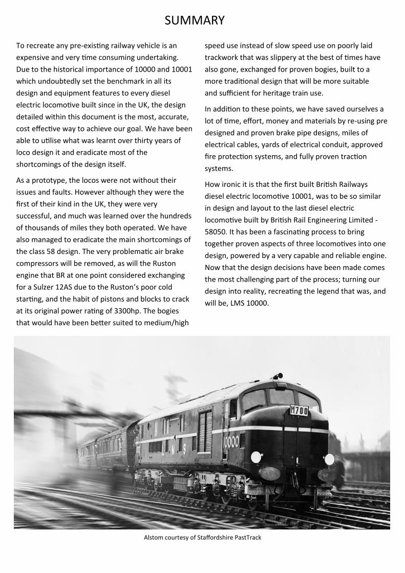
Alstom courtesy of Staffordshire PastTrack
Red Diamond Diesel Construction - D16/1a engineering and design overview Page 15 of 16
Red Diamond Diesel Construction Limited
89 Granville Street, Woodville, DE11 7JH
Website: www.red-diamond-diesel.co.uk
LMS10000
46 Biddick Village Centre, Washington, NE38 7NP
[email protected] 0755 162 1685
Website: www.lms10000.co.uk
Centenary Works
Station Road, Coldwell Street, Wirksworth, DE4 4FB
CONTACT
All photographs courtesy of the Ivatt Diesel re-creation Society or photographer unknown, unless stated.

www.red-diamond-diesel.co.uk


![7748655w[1] Installation D5~D16](https://img.pdfslide.us/doc/110x75/577ccd1c1a28ab9e788b85d7/7748655w1-installation-d5d16.jpg)