Embed Size (px)
Citation preview
Laser LA-4POperating instructionsGB
A2
4
7
6
12
11
1
8
10
14b
9
3a
3a
3c3b
5
14a
14c
11
F
CB
ED
GØ 50mm - 115 mm
1.
2.
Ø 2” - 4,5”
I K
L M
s> 6m
N Q
O
P1
P2
> 20ft
13
10
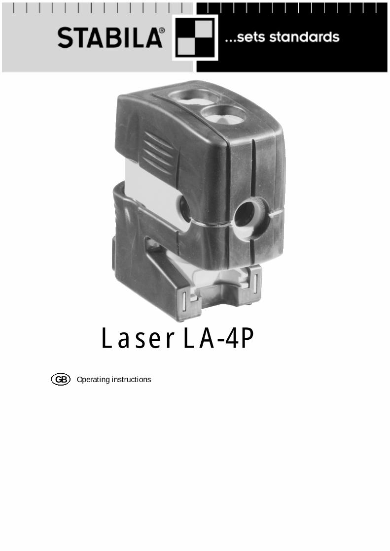
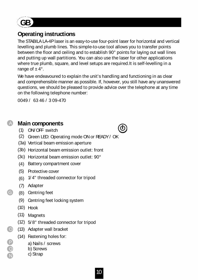
Protective cover
Centring feet
0049 / 63 46 / 3 09-470
G
Hook
Magnets
(1)
(3a)
(2)
(4)
(5)
(6)
(7)
(8)
(9)
(10)
(11)
(12)
(13)
(14)
A
Adapter
Adapter wall bracket
(3b) Horizontal beam emission outlet: front
(3c) Horizontal beam emission outlet: 90°
Fastening holes for:
a) Nails / screwsb) Screwsc) Strap
Centring feet locking system
O
Q
P
N
Vertical beam emission aperture
ON/OFF switch
5/8" threaded connector for tripod
Battery compartment cover
GB
Main components
The STABILA LA-4P laser is an easy-to-use four-point laser for horizontal and verticallevelling and plumb lines. This simple-to-use tool allows you to transfer pointsbetween the floor and ceiling and to establish 90° points for laying out wall linesand putting up wall partitions. You can also use the laser for other applicationswhere true plumb, square, and level setups are required.It is self-levelling in a range of ± 4°.
We have endeavoured to explain the unit's handling and functioning in as clearand comprehensible manner as possible. If, however, you still have any unansweredquestions, we should be pleased to provide advice over the telephone at any timeon the following telephone number:
Operating instructions
Green LED: Operating mode ON or READY / OK
1/4" threaded connector for tripod
11
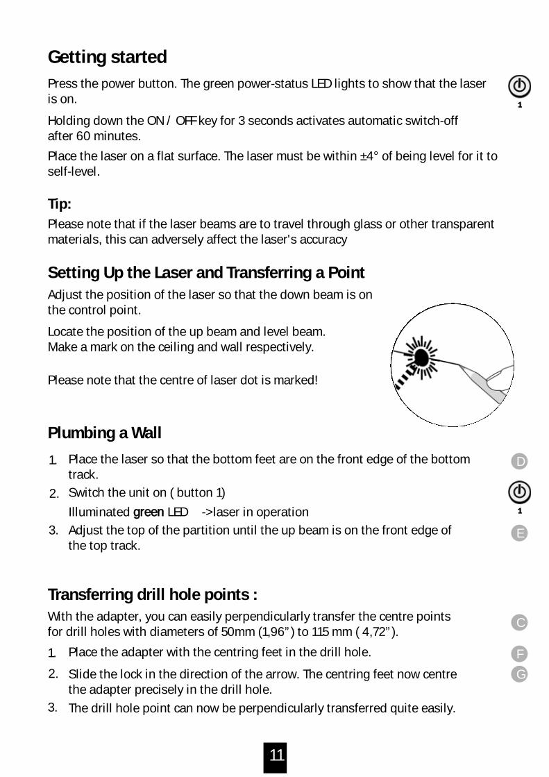
Getting started
Please note that if the laser beams are to travel through glass or other transparentmaterials, this can adversely affect the laser's accuracy
Press the power button. The green power-status LED lights to show that the laseris on.
Setting Up the Laser and Transferring a Point
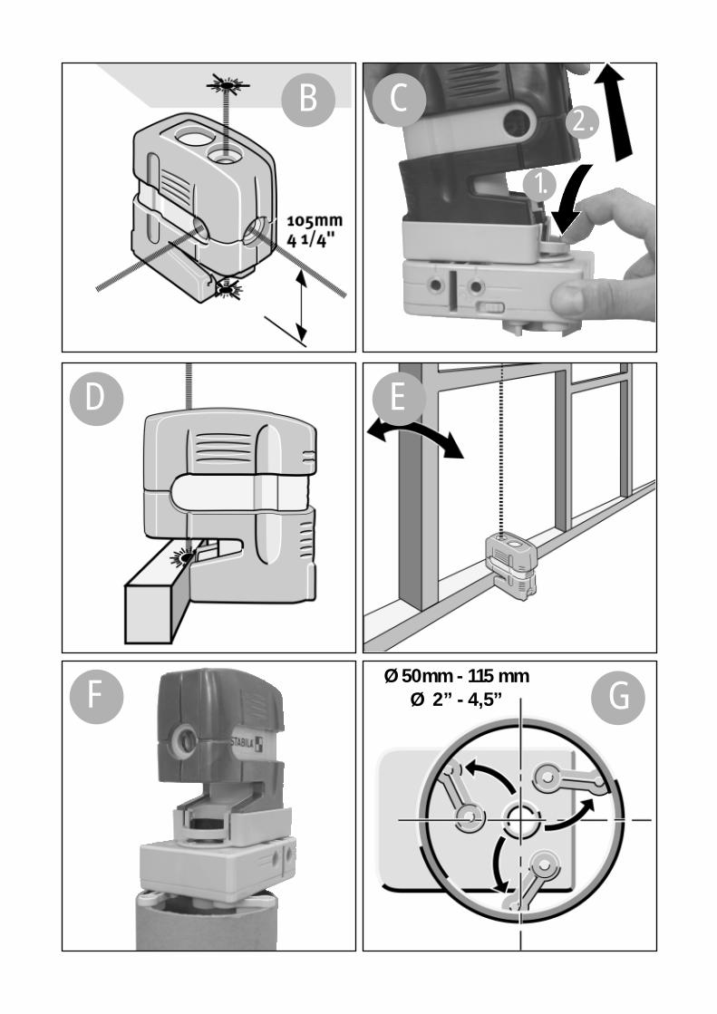
Locate the position of the up beam and level beam.Make a mark on the ceiling and wall respectively.
Adjust the position of the laser so that the down beam is onthe control point.
Place the laser so that the bottom feet are on the front edge of the bottomtrack.
Plumbing a Wall
Please note that the centre of laser dot is marked!
Place the laser on a flat surface. The laser must be within ±4° of being level for it toself-level.
Holding down the ON / OFF key for 3 seconds activates automatic switch-offafter 60 minutes.
1.
3.
2.
Tip:
Place the adapter with the centring feet in the drill hole.
The drill hole point can now be perpendicularly transferred quite easily.
Slide the lock in the direction of the arrow. The centring feet now centrethe adapter precisely in the drill hole.
1.
3.
2.
With the adapter, you can easily perpendicularly transfer the centre pointsfor drill holes with diameters of 50mm (1,96”) to 115 mm ( 4,72”).
Transferring drill hole points :
E
D
F
G
1
1
Adjust the top of the partition until the up beam is on the front edge ofthe top track.
Switch the unit on ( button 1)
Illuminated ggrreeeenn LED -> laser in operation
C
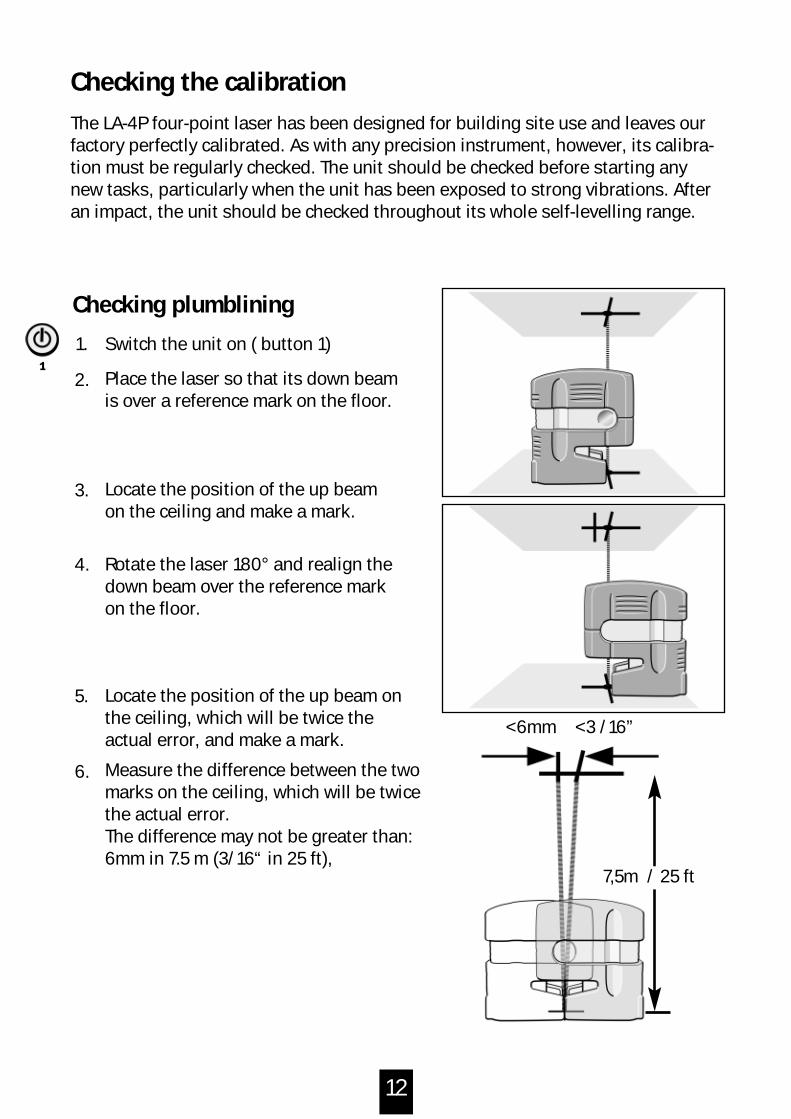
< 3 /16”
7,5m / 25 ft
< 6mm
1.
Checking plumblining
2.
3.
6.
Locate the position of the up beamon the ceiling and make a mark.
Locate the position of the up beam onthe ceiling, which will be twice theactual error, and make a mark.
Measure the difference between the twomarks on the ceiling, which will be twicethe actual error. The difference may not be greater than:6mm in 7.5 m (3/16“ in 25 ft),
5.
Rotate the laser 180° and realign thedown beam over the reference markon the floor.
4.
Place the laser so that its down beamis over a reference mark on the floor.
Switch the unit on ( button 1)1
The LA-4P four-point laser has been designed for building site use and leaves ourfactory perfectly calibrated. As with any precision instrument, however, its calibra-tion must be regularly checked. The unit should be checked before starting anynew tasks, particularly when the unit has been exposed to strong vibrations. Afteran impact, the unit should be checked throughout its whole self-levelling range.
Checking the calibration
12
13
I
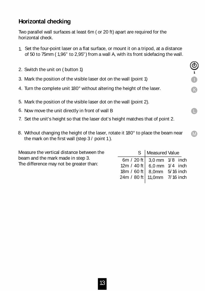
Horizontal checking
1.
2.
3.
7.
4.
5.
6.
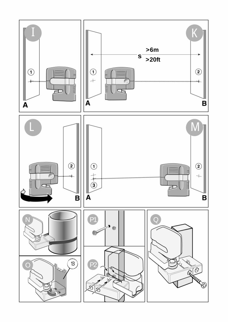
Mark the position of the visible laser dot on the wall (point 2).
Mark the position of the visible laser dot on the wall (point 1)
Switch the unit on ( button 1)
Set the four-point laser on a flat surface, or mount it on a tripod, at a distanceof 50 to 75mm ( 1,96” to 2,95”) from a wall A, with its front sidefacing the wall.
Turn the complete unit 180° without altering the height of the laser.
Two parallel wall surfaces at least 6m ( or 20 ft) apart are required for the horizontal check.
1
Without changing the height of the laser, rotate it 180° to place the beam nearthe mark on the first wall (step 3 / point 1 ).
Measure the vertical distance between thebeam and the mark made in step 3. The difference may not be greater than:
Measured ValueS
Now move the unit directly in front of wall B
Set the unit's height so that the laser dot's height matches that of point 2.
K
L
8. M
3,0 mm6,0 mm8,0mm
11,0mm
/ 20 ft/ 40 ft/ 60 ft/ 80 ft
6m12m18m24m
1/8 inch1/4 inch5/16 inch7/16 inch
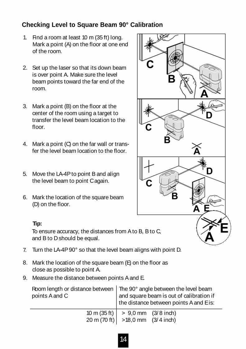
> 9,0 mm (3/8 inch)> 18,0 mm (3/4 inch)
14
1. Find a room at least 10 m (35 ft) long.Mark a point (A) on the floor at one endof the room.
2. Set up the laser so that its down beamis over point A. Make sure the levelbeam points toward the far end of theroom.
3. Mark a point (B) on the floor at the center of the room using a target totransfer the level beam location to thefloor.
6. Mark the location of the square beam(D) on the floor.
Turn the LA-4P 90° so that the level beam aligns with point D.7.
Mark the location of the square beam (E) on the floor asclose as possible to point A.
8.
Measure the distance between points A and E.9.
5. Move the LA-4P to point B and align the level beam to point C again.
4. Mark a point (C) on the far wall or trans-fer the level beam location to the floor.
To ensure accuracy, the distances from A to B, B to C,and B to D should be equal.
Tip:
Room length or distance betweenpoints A and C
The 90° angle between the level beamand square beam is out of calibration ifthe distance between points A and E is:
10 m (35 ft)20 m (70 ft)
Checking Level to Square Beam 90° Calibration
15
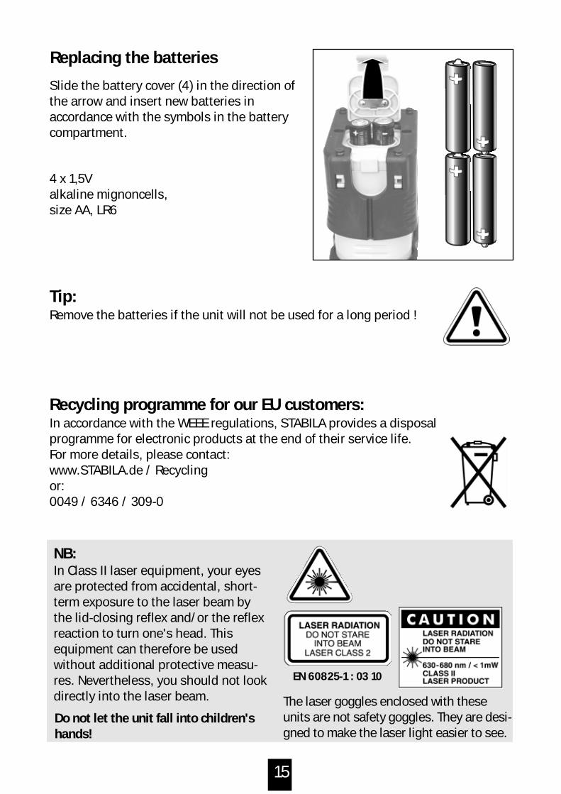
Replacing the batteries
Slide the battery cover (4) in the direction ofthe arrow and insert new batteries in accordance with the symbols in the batterycompartment.
4 x 1,5Valkaline mignoncells, size AA, LR6
Tip:Remove the batteries if the unit will not be used for a long period !
Recycling programme for our EU customers:In accordance with the WEEE regulations, STABILA provides a disposalprogramme for electronic products at the end of their service life.For more details, please contact: www.STABILA.de / Recycling or: 0049 / 6346 / 309-0
NB:In Class II laser equipment, your eyesare protected from accidental, short-term exposure to the laser beam bythe lid-closing reflex and/or the reflexreaction to turn one's head. Thisequipment can therefore be usedwithout additional protective measu-res. Nevertheless, you should not lookdirectly into the laser beam. The laser goggles enclosed with these
units are not safety goggles. They are desi-gned to make the laser light easier to see.
Do not let the unit fall into children'shands!
EN 60825-1 : 03 10
16
• Dirty lens glass on the beam emitter detracts from the quality of the beam. It should be cleaned with a soft cloth.
• Clean the laser unit with a damp cloth. Do not spray or immerse the unit! Do not use solvents or thinners!
Care and maintenance
The LA-4P four-point laser must be handled carefully, in the same way as anyprecision optical instrument.
Operating status display and error messages via the LEDs
Illuminated ggrreeeenn LED -> laser in operation
-> laser in operation-> battery voltage very low-> battery replacement required imminently
Laser beam ffllaasshhiinngg -> The unit is inclined too much + is outside the self-levelling range + the laser cannot level itself automatically
FFllaasshhiinngg ggrreeeenn LED
Tip:The laser unit should be allowed sufficient time to adjust to the ambienttemperature before you start it up. For example, when the laser is brought from an extremely hot / cold vehicleonto the building site.
When you’re not using the laser, store it in its pouch/carrying case.
Do not store the laser in a wet pouch/carrying case. If the pouch/carrying case gets wet, let it dry before storing the laser in it.
Do not submerge the laser.
17
Stabila provides a guarantee against deficiencies and faults in the assured characte-ristics because of material or manufacturing faults for a period of 24 months fromdate of purchase. Any faults will be eliminated at Stabila's own discretion either byrepairing or replacing the unit. Stabila accepts no wider claims. No liability is accepted for any faults due to inappropriate treatment (e.g. damagecaused by the unit falling, operation with the wrong voltage or type of current, use ofunsuitable current supply sources) or for any autonomous changes made to the unitby the purchaser or a third party. Also no claims under guarantee are accepted for natural wear and tear or any smallfaults that do not significantly affect the unit's operation.Any guarantee claims must be made via the dealer on the duly completed guaranteeform (see last page) to be returned with the unit.
Guarantee terms and conditions
Subject to technical modifications.
Laser type:
Technical data
Self-levelling range: *:(horizontal)
Output:
Levelling accuracy:
Batteries:
Operating life:
Operating temperature range:
Red diode laser, wavelength 635 nm
< 1 mW, Laser Class 2 to EN 60825-1:03-10
ca. ± 4°
± 1 mm / 0,5m
4 x 1,5 V Mignon cells Alkaline, Size AA, LR6
Approx. 40 hours
-10 °C to +45 °C (14 °F to 113 °F)
Up Beam Accuracy*:
Down Beam Accuracy
Level Beam Accuracy*:
Square Beam Accuracy*:
± 6 mm / 21m
± 6 mm / 30m
± 6 mm / 30m
* At 20°C ( 50°F )
Working Range*: 20-30m (65–100 ft)
( +/– 1/4 in. @ 70 ft )
( +/– 1/16 in. @ 2.5 ft )
( +/– 1/4 in. @ 100 ft )
( +/– 1/4 in. @ 100 ft )