Embed Size (px)
Citation preview
NDTCE’09, Non-Destructive Testing in Civil EngineeringNantes, France, June 30th – July 3rd, 2009
Laser interferometer robot for the detection of voids in tendon ducts with the impact echo method
Odile ABRAHAM1, Louis-Marie COTTINEAU1, Michel VALADE2, Safia BEDAOUI3, Pierre ARGOUL3
1 LCPC, Bouguenais, France, [email protected] LRPC, Lyon, France 3 Université Paris-Est, UR Navier, ENPC, Marne la Vallée, France
AbstractThe detection of voids in tendon ducts with the impact echo method is a real challenge as it
could result in the diminution of gammagraphy need. Two major phenomena are indicative of the presence of a void in the impact echo method: a decrease of the thickness resonance frequency f e and the apparition of a higher frequency in the literature named f void . The first observable alone might be in a number of case misleading as a frequency shift has been sometime observed above tendon that are diagnosed as fully filled by gammagraphy. The addition of another observable ( f void ) that confirms the existence of a void is thus welcome for it will ascertain the diagnosis. Unfortunately the high frequency content of the impact echo signal is difficult to record, first because sending energy in this frequency range is difficult with a small steel ball, second because scattering and damping exist and third because traditional contact transducer are not optimal in this frequency range. In this paper, we show that the use of a laser interferometer which has a large bandwidth offers the possibility to record simultaneously both observables.
RésuméLa détection de vides dans les gaines de précontrainte avec la méthode impact echo est un
réel challenge car elle pourrait diminuer l'utilisation de la gammagraphie. Deux phénomènes principaux sont observés en cas de vide : une diminution de la fréquence caractéristique de l'épaisseur f e et l'apparition d'un nouveau pic haute fréquence dénommé f void dans la littérature. La première observable peut conduire à des erreurs de diagnostic car un décalage est parfois observé lorsque la gammagraphie indique que la gaine est totalement pleine. L'ajout d'une autre observable ( f void ) qui confirme l'existence d'un vide est donc bienvenue pour la pertinence du diagnostic. Malheureusement l'enregistrement du contenu haute fréquence est difficile, premièrement parce que la génération du signal dans cette gamme de fréquence est difficile (avec de petite bille de métal), deuxièmement parce que la diffraction et l'atténuation existent et troisièmement parce que les capteurs traditionnels qui requièrent un contact ne sont pas optimaux. Dans cet article, nous montrons que l'utilisation d'un interféromètre laser, avec une large bande passante, offre la possibilité d'enregistrer ces deux observables en même temps.
KeywordsConcrete, Zero Group Velocity, Lamb, B-SCAN, C-SCAN
1 Introduction
The auscultation of tendon duct is a major issue in France and a dedicated research project named ACTENA, directed by the Laboratoire Central des Ponts et Chaussées and Electricité De France has been running on this topic from 2005 to 2008. In this project, the impact echo method was considered as a potential method that could localize possible faulty zone (air in tendon duct), like gammagraphy, but with a non ionizing non destructive method. As stated
NDTCE’09, Non-Destructive Testing in Civil EngineeringNantes, France, June 30th – July 3rd, 2009
previously [1,2] in order to carry out reproducible and reliable impact echo diagnosis imagery, using B-SCAN or C-SCAN, is recommended. This is why a robot was designed to cover metric scale surfaces impact echo measurements. This kind of robot is not a new idea as, for instance, BAM has been performing such measurements with robot since the beginning of 2000 years [3]. The originality of LCPC robot is to use a non contact device, a laser interferometer, as a receiver. Our aim is to promote non contact NDT measurements, one of which could use laser interferometry, for civil engineering needs (wide coverage for bridges, long linear measurement for roads). One advantage of a laser interferometer is its large frequency range covering easily all impact echo frequency spectrum (here from 1 kHz up to 50 kHz).
The objective of this paper is to describe this device and to show our first results with regards to void detection in tendon ducts. We show that the laser interferometer makes it possible to follow simultaneously the thickness frequency shift above a void together with the modification of the spectrum in the high frequency domain near the commonly called f void frequency. This last objective (high frequency study) is rendered difficult because the generation of the signal has to be energetic enough to get a good signal to noise ratio with the laser interferometer.
2 Basic principle
Before the paper of Gibson & Popovics (2005) [4], the impact echo method principle was currently explained by multiple reflexion of P-wave generated by an impact on top of a slab [2]. In the frequency domain, this periodic phenomenon was leading to a resonance frequency f e almost a function of solely the thickness e and the P-wave velocity V P . The almost is
related to the existence of a shape factor β observed both experimentally and numerically (finite element computation), nearly equal to one, in the “impact echo” equation :
f e =βV P
2 e (1)
This principle has recently been revised [1] to give a complete explanation of the observe resonance frequency equation f e . The phenomenon relies on Lamb wave first symmetric mode S1 that, for values of the Poisson coefficient between 0 and 0.45 has a frequency at which the phase velocity is finite while the group velocity is zero. This frequency, also called the ZGV (Zero Group Velocity) frequency of the first symmetric Lamb mode S1 is the impact echo thickness frequency [6].
In the presence of a void, the frequency f e is reduced. In the past, an explanation was that the travel of the P-wave was increased due to the void. This geometric explanation was invalidated by numerical computation in [1]. With regard to Lamb wave stationary phenomenon, this decrease may be due to a diminution of the slab local stiffness.
Moreover, it was also supposed that a new frequency should appear near a frequency called f void where in equation (1) the thickness e is replaced by the distance between the top of
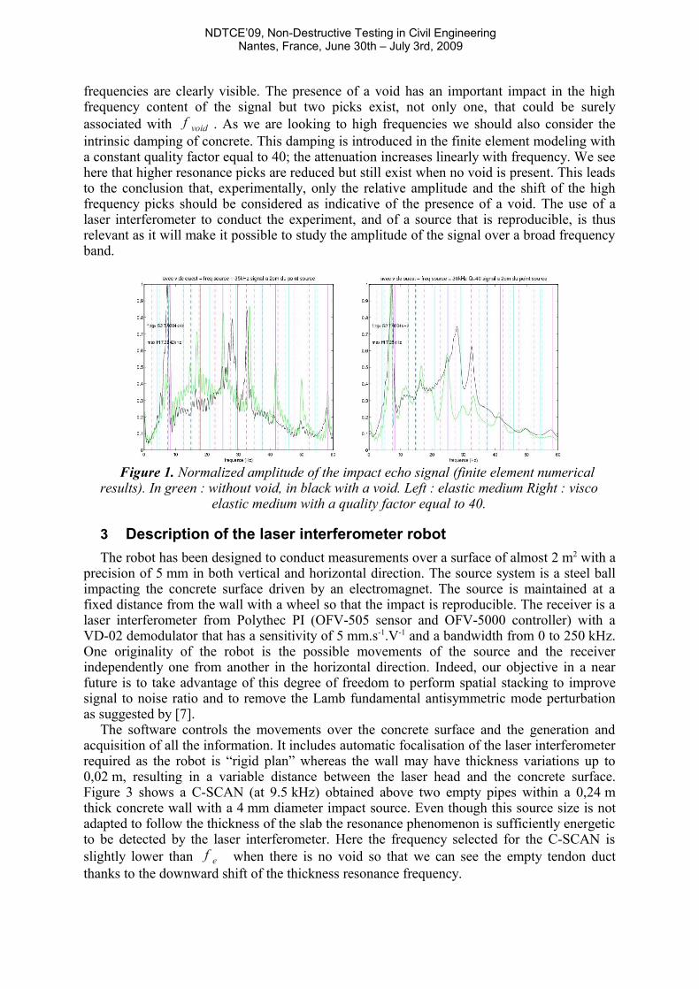
the slab to the top of the void. Numerical computations show that this phenomenon, in addition to being difficult to measure in the field as often mentioned in the literature, should be difficult to interpret as the Lamb wave propagation also induces higher resonance frequencies when no void exists: typically, one should observe the second anti symmetric ZGV frequency (A2 mode) and the critical frequencies of higher order Lamb modes. This is illustrated in Figure1 with numerical impact echo signal obtained with finite element computations with (black curves) and without (green curves) void and with and without intrinsic attenuation. The slab thickness is 0,24 m and the void, when present, is 0,045 m in diameter. The source is centered at 35 kHz to excite higher frequencies. The amplitude are normalized to one; in all cases the maximum is obtained at the thickness resonance frequency (ZGV frequency of Lamb mode S1). When there is no attenuation higher resonance
NDTCE’09, Non-Destructive Testing in Civil EngineeringNantes, France, June 30th – July 3rd, 2009
frequencies are clearly visible. The presence of a void has an important impact in the high frequency content of the signal but two picks exist, not only one, that could be surely associated with f void . As we are looking to high frequencies we should also consider the intrinsic damping of concrete. This damping is introduced in the finite element modeling with a constant quality factor equal to 40; the attenuation increases linearly with frequency. We see here that higher resonance picks are reduced but still exist when no void is present. This leads to the conclusion that, experimentally, only the relative amplitude and the shift of the high frequency picks should be considered as indicative of the presence of a void. The use of a laser interferometer to conduct the experiment, and of a source that is reproducible, is thus relevant as it will make it possible to study the amplitude of the signal over a broad frequency band.
Figure 1. Normalized amplitude of the impact echo signal (finite element numerical
results). In green : without void, in black with a void. Left : elastic medium Right : visco elastic medium with a quality factor equal to 40.
3 Description of the laser interferometer robot
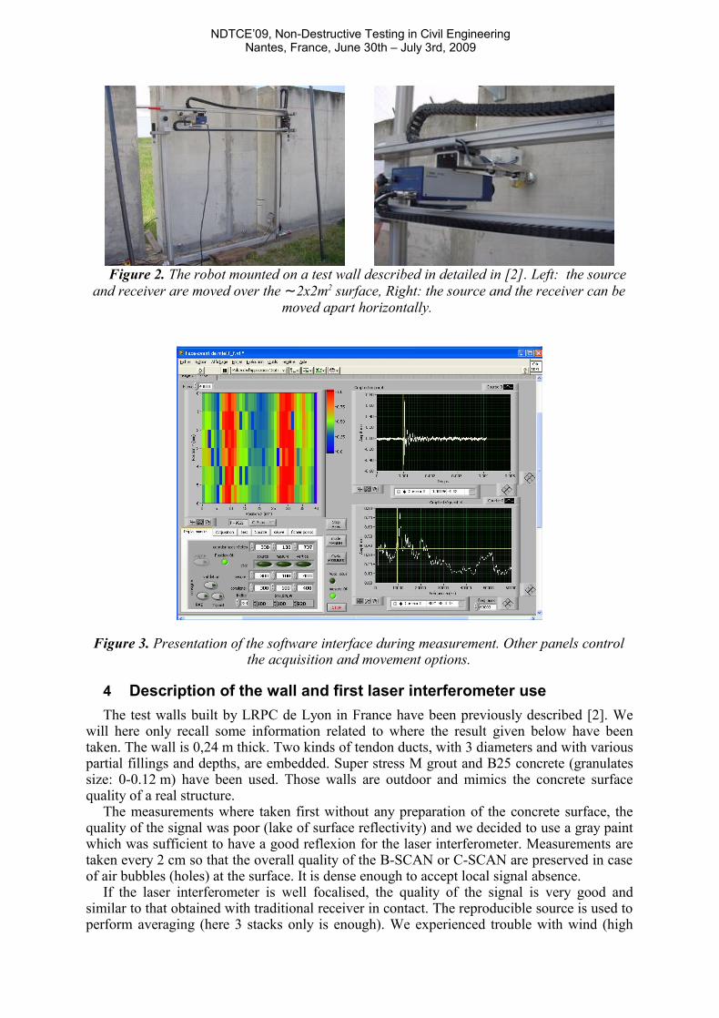
The robot has been designed to conduct measurements over a surface of almost 2 m2 with a precision of 5 mm in both vertical and horizontal direction. The source system is a steel ball impacting the concrete surface driven by an electromagnet. The source is maintained at a fixed distance from the wall with a wheel so that the impact is reproducible. The receiver is a laser interferometer from Polythec PI (OFV-505 sensor and OFV-5000 controller) with a VD-02 demodulator that has a sensitivity of 5 mm.s-1.V-1 and a bandwidth from 0 to 250 kHz. One originality of the robot is the possible movements of the source and the receiver independently one from another in the horizontal direction. Indeed, our objective in a near future is to take advantage of this degree of freedom to perform spatial stacking to improve signal to noise ratio and to remove the Lamb fundamental antisymmetric mode perturbation as suggested by [7].
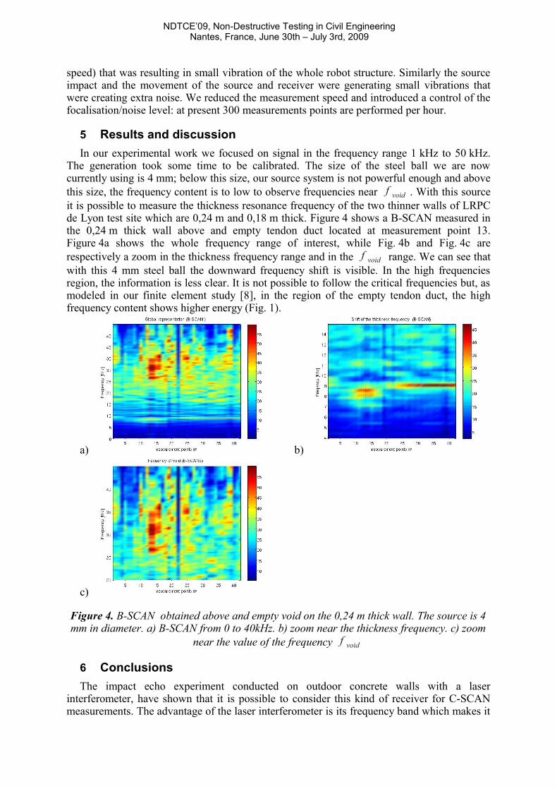
The software controls the movements over the concrete surface and the generation and acquisition of all the information. It includes automatic focalisation of the laser interferometer required as the robot is “rigid plan” whereas the wall may have thickness variations up to 0,02 m, resulting in a variable distance between the laser head and the concrete surface. Figure 3 shows a C-SCAN (at 9.5 kHz) obtained above two empty pipes within a 0,24 m thick concrete wall with a 4 mm diameter impact source. Even though this source size is not adapted to follow the thickness of the slab the resonance phenomenon is sufficiently energetic to be detected by the laser interferometer. Here the frequency selected for the C-SCAN is slightly lower than f e when there is no void so that we can see the empty tendon duct thanks to the downward shift of the thickness resonance frequency.
NDTCE’09, Non-Destructive Testing in Civil EngineeringNantes, France, June 30th – July 3rd, 2009
Figure 2. The robot mounted on a test wall described in detailed in [2]. Left: the source
and receiver are moved over the ~2x2m2 surface, Right: the source and the receiver can be moved apart horizontally.
Figure 3. Presentation of the software interface during measurement. Other panels control the acquisition and movement options.
4 Description of the wall and first laser interferometer use
The test walls built by LRPC de Lyon in France have been previously described [2]. We will here only recall some information related to where the result given below have been taken. The wall is 0,24 m thick. Two kinds of tendon ducts, with 3 diameters and with various partial fillings and depths, are embedded. Super stress M grout and B25 concrete (granulates size: 0-0.12 m) have been used. Those walls are outdoor and mimics the concrete surface quality of a real structure.
The measurements where taken first without any preparation of the concrete surface, the quality of the signal was poor (lake of surface reflectivity) and we decided to use a gray paint which was sufficient to have a good reflexion for the laser interferometer. Measurements are taken every 2 cm so that the overall quality of the B-SCAN or C-SCAN are preserved in case of air bubbles (holes) at the surface. It is dense enough to accept local signal absence.
If the laser interferometer is well focalised, the quality of the signal is very good and similar to that obtained with traditional receiver in contact. The reproducible source is used to perform averaging (here 3 stacks only is enough). We experienced trouble with wind (high
NDTCE’09, Non-Destructive Testing in Civil EngineeringNantes, France, June 30th – July 3rd, 2009
speed) that was resulting in small vibration of the whole robot structure. Similarly the source impact and the movement of the source and receiver were generating small vibrations that were creating extra noise. We reduced the measurement speed and introduced a control of the focalisation/noise level: at present 300 measurements points are performed per hour.
5 Results and discussion
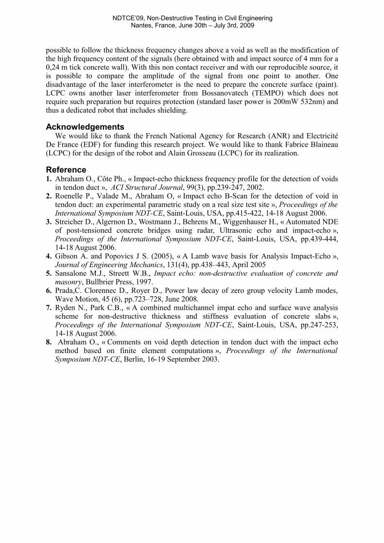
In our experimental work we focused on signal in the frequency range 1 kHz to 50 kHz. The generation took some time to be calibrated. The size of the steel ball we are now currently using is 4 mm; below this size, our source system is not powerful enough and above this size, the frequency content is to low to observe frequencies near f void . With this source it is possible to measure the thickness resonance frequency of the two thinner walls of LRPC de Lyon test site which are 0,24 m and 0,18 m thick. Figure 4 shows a B-SCAN measured in the 0,24 m thick wall above and empty tendon duct located at measurement point 13. Figure 4a shows the whole frequency range of interest, while Fig. 4b and Fig. 4c are respectively a zoom in the thickness frequency range and in the f void range. We can see that with this 4 mm steel ball the downward frequency shift is visible. In the high frequencies region, the information is less clear. It is not possible to follow the critical frequencies but, as modeled in our finite element study [8], in the region of the empty tendon duct, the high frequency content shows higher energy (Fig. 1).
a) b)
c)
Figure 4. B-SCAN obtained above and empty void on the 0,24 m thick wall. The source is 4 mm in diameter. a) B-SCAN from 0 to 40kHz. b) zoom near the thickness frequency. c) zoom
near the value of the frequency f void
6 Conclusions
The impact echo experiment conducted on outdoor concrete walls with a laser interferometer, have shown that it is possible to consider this kind of receiver for C-SCAN measurements. The advantage of the laser interferometer is its frequency band which makes it
NDTCE’09, Non-Destructive Testing in Civil EngineeringNantes, France, June 30th – July 3rd, 2009
possible to follow the thickness frequency changes above a void as well as the modification of the high frequency content of the signals (here obtained with and impact source of 4 mm for a 0,24 m tick concrete wall). With this non contact receiver and with our reproducible source, it is possible to compare the amplitude of the signal from one point to another. One disadvantage of the laser interferometer is the need to prepare the concrete surface (paint). LCPC owns another laser interferometer from Bossanovatech (TEMPO) which does not require such preparation but requires protection (standard laser power is 200mW 532nm) and thus a dedicated robot that includes shielding.
AcknowledgementsWe would like to thank the French National Agency for Research (ANR) and Electricité
De France (EDF) for funding this research project. We would like to thank Fabrice Blaineau (LCPC) for the design of the robot and Alain Grosseau (LCPC) for its realization.
Reference 1. Abraham O., Côte Ph., « Impact-echo thickness frequency profile for the detection of voids
in tendon duct », ACI Structural Journal, 99(3), pp.239-247, 2002.2. Roenelle P., Valade M., Abraham O, « Impact echo B-Scan for the detection of void in
tendon duct: an experimental parametric study on a real size test site », Proceedings of the International Symposium NDT-CE, Saint-Louis, USA, pp.415-422, 14-18 August 2006.
3. Streicher D., Algernon D., Wostmann J., Behrens M., Wiggenhauser H., « Automated NDE of post-tensioned concrete bridges using radar, Ultrasonic echo and impact-echo », Proceedings of the International Symposium NDT-CE, Saint-Louis, USA, pp.439-444, 14-18 August 2006.
4. Gibson A. and Popovics J S. (2005), « A Lamb wave basis for Analysis Impact-Echo », Journal of Engineering Mechanics, 131(4), pp.438–443, April 2005
5. Sansalone M.J., Streett W.B., Impact echo: non-destructive evaluation of concrete and masonry, Bullbrier Press, 1997.
6. Prada,C. Clorennec D., Royer D., Power law decay of zero group velocity Lamb modes, Wave Motion, 45 (6), pp.723–728, June 2008.
7. Ryden N., Park C.B., « A combined multichannel impat echo and surface wave analysis scheme for non-destructive thickness and stiffness evaluation of concrete slabs », Proceedings of the International Symposium NDT-CE, Saint-Louis, USA, pp.247-253, 14-18 August 2006.
8. Abraham O., « Comments on void depth detection in tendon duct with the impact echo method based on finite element computations », Proceedings of the International Symposium NDT-CE, Berlin, 16-19 September 2003.