Embed Size (px)
Citation preview
1 | P a g e
Laser Engraved Filled Images and Letters by: Ed Powell
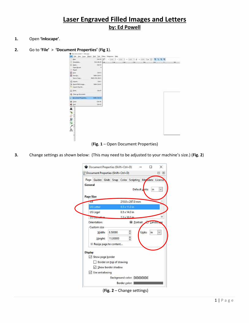
1. Open ‘Inkscape’. 2. Go to ‘File’ > ‘Document Properties’ (Fig 1).
(Fig. 1 – Open Document Properties)
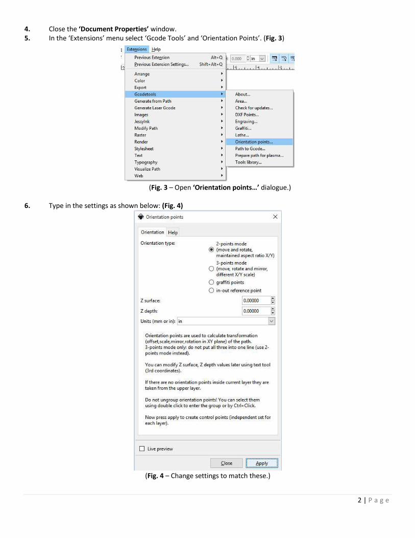
3. Change settings as shown below: (This may need to be adjusted to your machine’s size.) (Fig. 2)
(Fig. 2 – Change settings)
2 | P a g e
4. Close the ‘Document Properties’ window. 5. In the ‘Extensions’ menu select ‘Gcode Tools’ and ‘Orientation Points’. (Fig. 3)
(Fig. 3 – Open ‘Orientation points…’ dialogue.)
6. Type in the settings as shown below: (Fig. 4)
(Fig. 4 – Change settings to match these.)
3 | P a g e
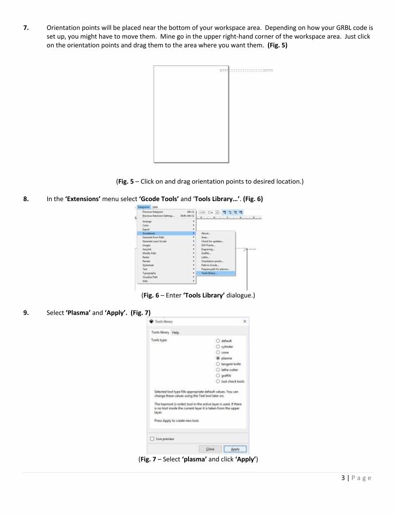
7. Orientation points will be placed near the bottom of your workspace area. Depending on how your GRBL code is set up, you might have to move them. Mine go in the upper right-hand corner of the workspace area. Just click on the orientation points and drag them to the area where you want them. (Fig. 5)
(Fig. 5 – Click on and drag orientation points to desired location.)
8. In the ‘Extensions’ menu select ‘Gcode Tools’ and ‘Tools Library…’. (Fig. 6)
(Fig. 6 – Enter ‘Tools Library’ dialogue.)
9. Select ‘Plasma’ and ‘Apply’. (Fig. 7)
(Fig. 7 – Select ‘plasma’ and click ‘Apply’)
4 | P a g e
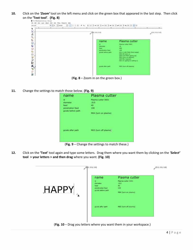
10. Click on the ‘Zoom’ tool on the left menu and click on the green box that appeared in the last step. Then click on the ‘Text tool’. (Fig. 8)
(Fig. 8 – Zoom in on the green box.)
11. Change the settings to match those below. (Fig. 9)
(Fig. 9 – Change the settings to match these.)
12. Click on the ‘Text’ tool again and type some letters. Drag them where you want them by clicking on the ‘Select’
tool > your letters > and then drag where you want. (Fig. 10)
(Fig. 10 – Drag you letters where you want them in your workspace.)
5 | P a g e
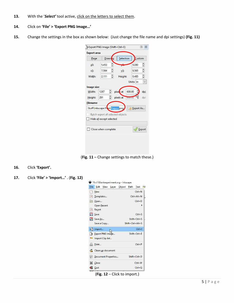
13. With the ‘Select’ tool active, click on the letters to select them. 14. Click on ‘File’ > ‘Export PNG Image…’ 15. Change the settings in the box as shown below: (Just change the file name and dpi settings) (Fig. 11)
(Fig. 11 – Change settings to match these.)
16. Click ‘Export’. 17. Click ‘File’ > ‘Import…’ . (Fig. 12)
(Fig. 12 – Click to import.)
6 | P a g e
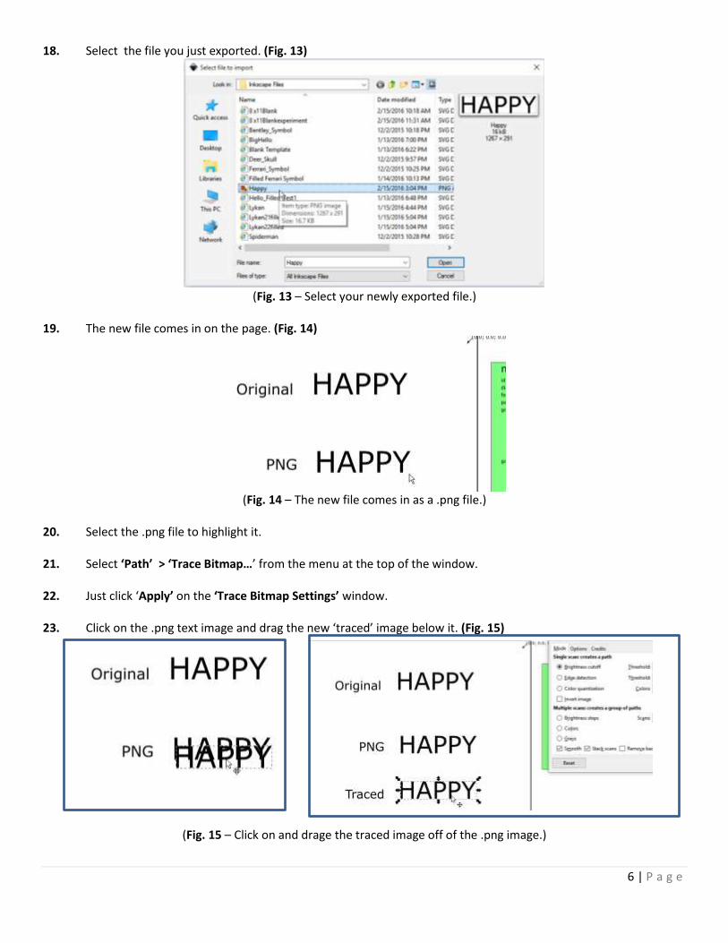
18. Select the file you just exported. (Fig. 13)
(Fig. 13 – Select your newly exported file.)
19. The new file comes in on the page. (Fig. 14)
(Fig. 14 – The new file comes in as a .png file.)
20. Select the .png file to highlight it. 21. Select ‘Path’ > ‘Trace Bitmap…’ from the menu at the top of the window. 22. Just click ‘Apply’ on the ‘Trace Bitmap Settings’ window. 23. Click on the .png text image and drag the new ‘traced’ image below it. (Fig. 15)
(Fig. 15 – Click on and drage the traced image off of the .png image.)
7 | P a g e
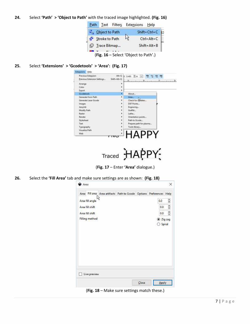
24. Select ‘Path’ > ‘Object to Path’ with the traced image highlighted. (Fig. 16)
(Fig. 16 – Select ‘Object to Path’.)
25. Select ‘Extensions’ > ‘Gcodetools’ > ‘Area’: (Fig. 17)
(Fig. 17 – Enter ‘Area’ dialogue.)
26. Select the ‘Fill Area’ tab and make sure settings are as shown: (Fig. 18)
(Fig. 18 – Make sure settings match these.)
8 | P a g e
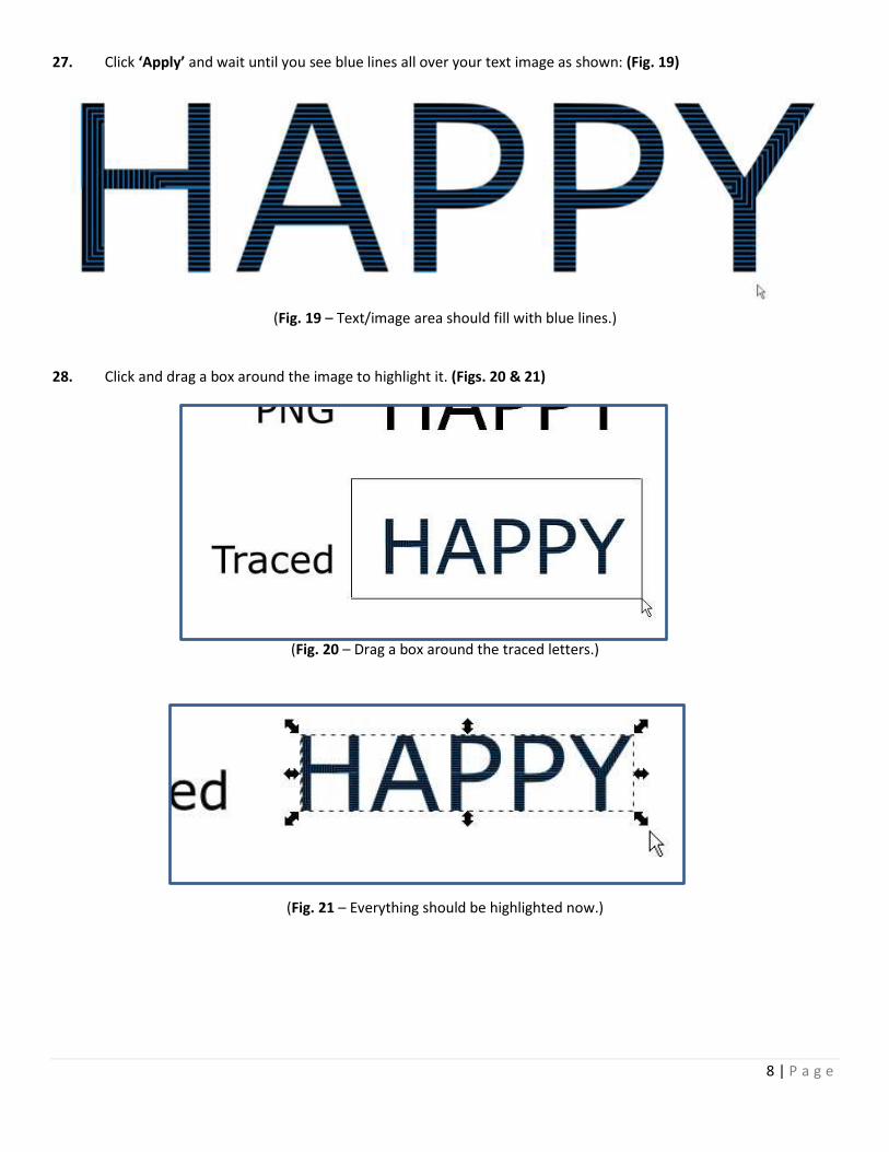
27. Click ‘Apply’ and wait until you see blue lines all over your text image as shown: (Fig. 19)
(Fig. 19 – Text/image area should fill with blue lines.)
28. Click and drag a box around the image to highlight it. (Figs. 20 & 21)
(Fig. 20 – Drag a box around the traced letters.)
(Fig. 21 – Everything should be highlighted now.)
9 | P a g e
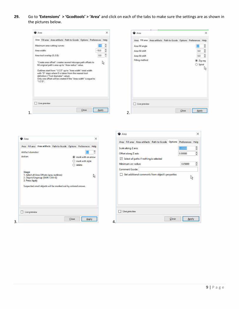
29. Go to ‘Extensions’ > ‘Gcodtools’ > ‘Area’ and click on each of the tabs to make sure the settings are as shown in the pictures below.
1. 2.
3. 4.
10 | P a g e
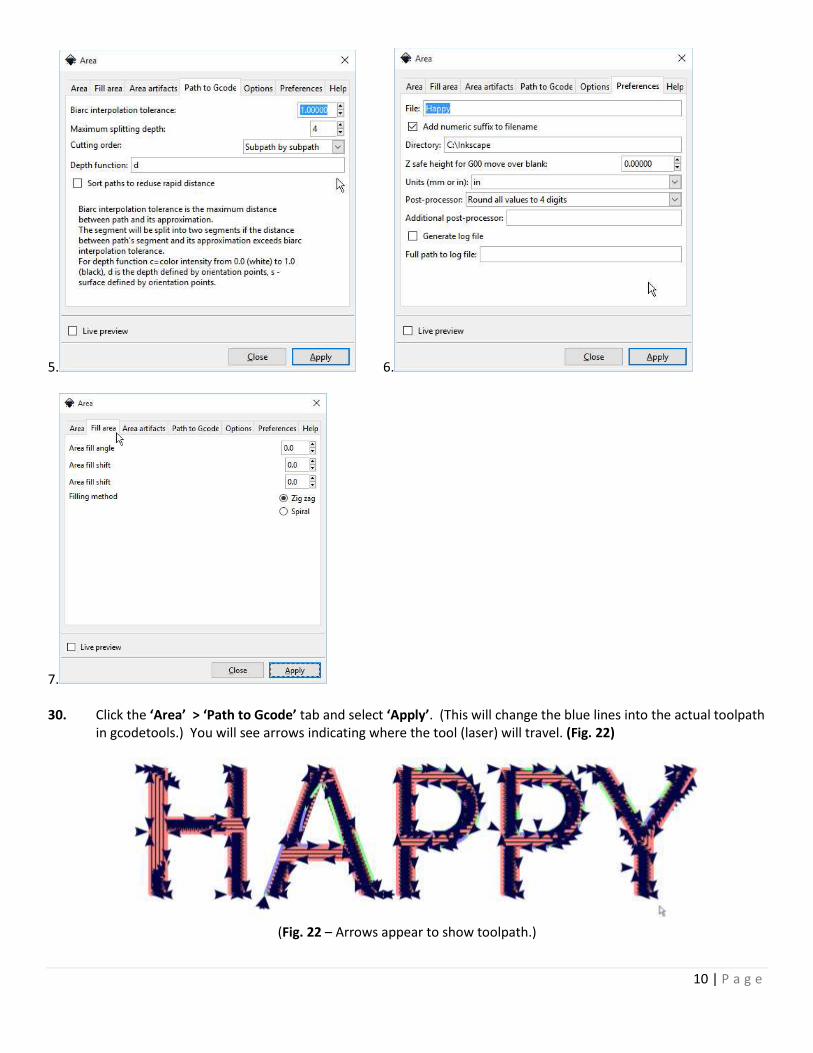
5. 6.
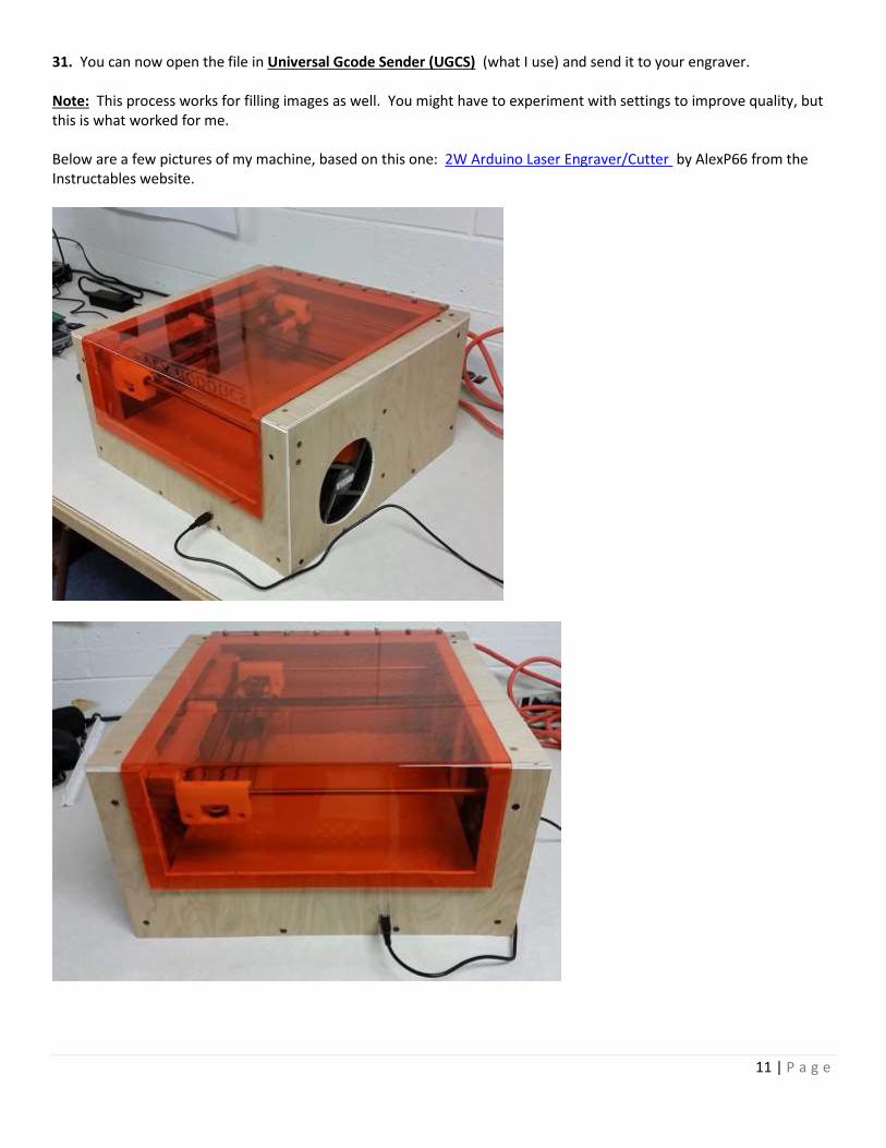
7. 30. Click the ‘Area’ > ‘Path to Gcode’ tab and select ‘Apply’. (This will change the blue lines into the actual toolpath
in gcodetools.) You will see arrows indicating where the tool (laser) will travel. (Fig. 22)
(Fig. 22 – Arrows appear to show toolpath.)
11 | P a g e
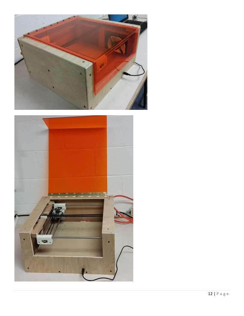
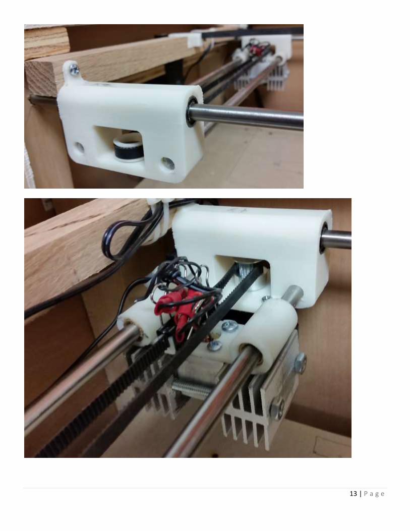
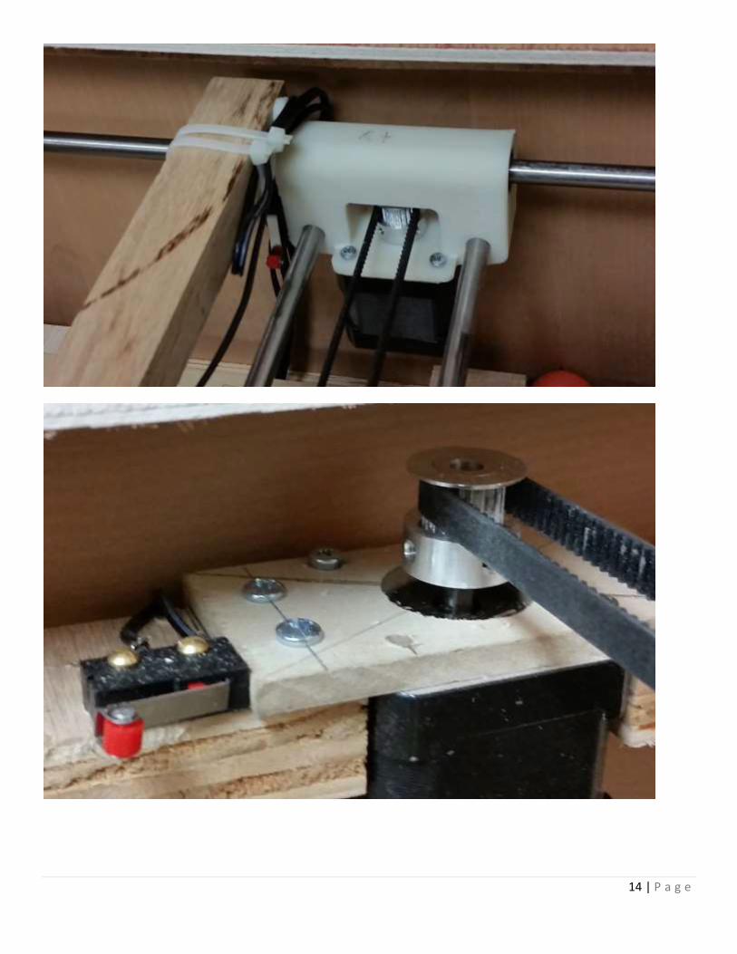
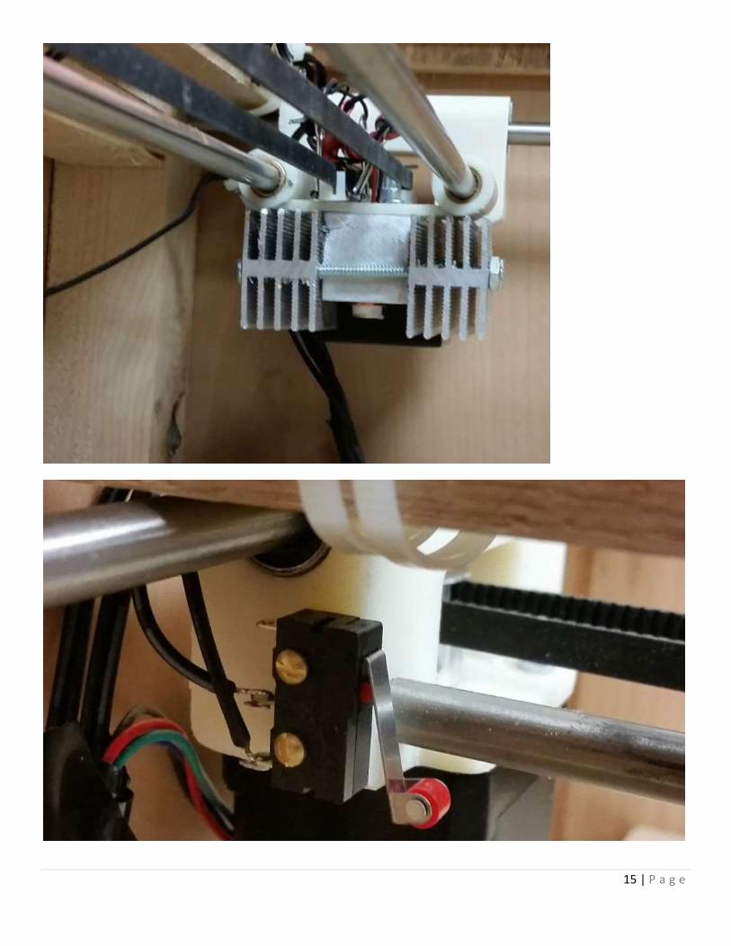
31. You can now open the file in Universal Gcode Sender (UGCS) (what I use) and send it to your engraver. Note: This process works for filling images as well. You might have to experiment with settings to improve quality, but this is what worked for me. Below are a few pictures of my machine, based on this one: 2W Arduino Laser Engraver/Cutter by AlexP66 from the Instructables website.
12 | P a g e
13 | P a g e
14 | P a g e
15 | P a g e

16 | P a g e