Embed Size (px)
Citation preview
Laser diode bistability as sensor of optical signals parameters A.P. Gonzalez-Marcos1, J.A. Martin-Pereda2, A. Hurtado3
E.T.S. Ingenieros de Telecomunicación. Universidad Politécnica de Madrid Ciudad Universitaria 28040. Madrid. Spain
ABSTRACT
Laser Diodes have been employed many times as light sources on different kinds of optical sensors. Their main function in these applications was the emission of an optical radiation impinging onto a certain object and, according to the characteristics of the reflected light, some information about this object was obtained. Laser diodes were acting, in a certain way, just as passive devices where their only function was to provide the adequate radiation to be later measured and analyzed. The objective of this paper is to report a new concept on the use of laser diodes taking into account their optical bistable properties. As it has been shown in several places, different laser diodes as, for example, DFB lasers and FP lasers, offer bistable characteristics being these characteristics a function of different parameters as wavelength, light polarization or temperature. Laser Bistability is strongly dependent on them and any small variation of above parameters gives rise to a strong change in the characteristics of its non-linear properties. These variations are analyzed and their application in sensing reported. The dependence on wavelength, spectral width, input power and phase variations, mainly for a Fabry-Perot Laser structure as basic configuration, is shown in this paper.
Keywords: optical sensor, laser diode bistability, optical measurements
1. INTRODUCCIÓN
Since the first optical bistability properties were obtained in laser diodes, many have been the attempts to employ them in different applications. In most of the cases they have been related with their use in optical computing architectures or in photonic switching configurations for optical communications. Several hundreds of papers have been published around this topic and many more will be published in the future. A common requirement in any one of these applications is the stability of the properties of the whole system. That means the final result has to be almost invariant when some minor changes appear in some of the basic parameters of the system. These changes may appear, in almost every case, as derived from small variations in external parameters that give rise to changes in the behaviour of some of the individual components of the system. One of the clearest examples appears, for instance, when self-electrooptic effect devices, SEEDs, are going to be applied in optical computing. As it is well known, the bistable properties of these components are strongly dependent on the values of several factors, namely, applied voltage to the SEED, wavelength and intensity of the impinging light, external circuit where the SEED is located, external temperature, light polarization and so on. A small change, for example, in light wavelength determines a strong change in the output-input characteristics of the device and, as a consequence, on the total behaviour of the structure where it is located. As it has been shown, when SEEDs are employed in optical computer architectures, small changes in its properties may affect to the final results of a computing architecture, changing the Boolean functions to be obtained. It is because that these devices are required to maintain their properties constant and many proposals have been published taking into account these possible changes.
Above indicated problems may become an advantage if the application of bistable properties is in optical sensors. Any optical sensor is as good as small changes in external parameters give rise to appreciable changes in its behaviour. It is because that most of the optical sensors developed in this field were based on interferometric methods, ranging from Sagnac to Mach-Zender configurations. These structures have been adapted nowadays to systems based on optical fibres or on integrated optics circuits. Basic principles remain the same and only the internal components or devices have been changed. Changes in intrinsic properties of the components, as changes in refractive index derived from temperature or in light propagation characteristics derived from external pressure, become the main source for the
1 [email protected] 2 [email protected] 3 [email protected]
152 Photonics North 2004: Photonic Applications in Telecommunications, Sensors, Software, and Lasers, edited by J. Armitage, R. Lessard, G. Lampropoulos, Proc. of SPIE Vol. 5579
(SPIE, Bellingham, WA, 2004) • 0277-786X/04/$15 • doi: 10.1117/12.567341
final result. In optical fibre sensors, for example, these external changes affect to the optical path followed by light through the fibre and, as a consequence, constructive or destructive interference phenomena may be observed in the interferometer. These structures are useful for a certain type of applications but, in some cases, some more compact configurations may be needed and some other physical quantities may be considered as the parameter to be measured. If this is the case, optical bistable properties of active devices are the main candidates to be employed.
2. LASER DIODE BIESTABILITY
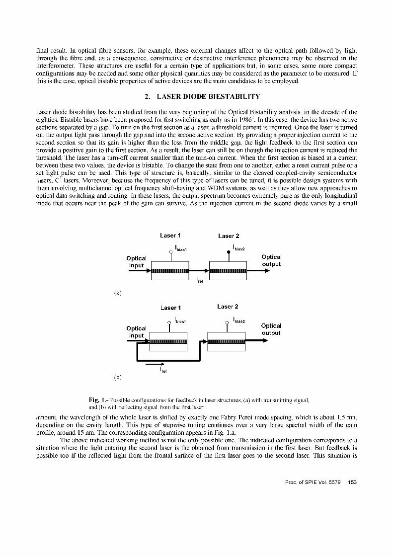
Laser diode bistability has been studied from the very beginning of the Optical Bistability analysis, in the decade of the eighties. Bistable lasers have been proposed for fast switching as early as in 19861. In this case, the device has two active sections separated by a gap. To turn on the first section as a laser, a threshold current is required. Once the laser is turned on, the output light pass through the gap and into the second active section. By providing a proper injection current to the second section so that its gain is higher than the loss from the middle gap, the light feedback to the first section can provide a positive gain to the first section. As a result, the laser can still be on though the injection current is reduced the threshold. The laser has a turn-off current smaller than the turn-on current. When the first section is biased at a current between these two values, the device is bistable. To change the state from one to another, either a reset current pulse or a set light pulse can be used. This type of structure is, basically, similar to the cleaved coupled-cavity semiconductor lasers, C3 lasers. Moreover, because the frequency of this type of lasers can be tuned, it is possible design systems with them involving multichannel optical frequency shift-keying and WDM systems, as well as they allow new approaches to optical data switching and routing. In these lasers, the output spectrum becomes extremely pure as the only longitudinal mode that occurs near the peak of the gain can survive. As the injection current in the second diode varies by a small
Laser 1 Laser 2
0 'biasl 'bias2
Optical ] ] Optical
(a)
Laser 1 Laser 2
(b)
Fig. 1.- Possible configurations for feedback in laser structures, (a) with transmitting signal, and (b) with reflecting signal from the first laser.
amount, the wavelength of the whole laser is shifted by exactly one Fabry Perot mode spacing, which is about 1,5 nm, depending on the cavity length. This type of stepwise tuning continues over a very large spectral width of the gain profile, around 15 nm. The corresponding configuration appears in Fig. La.
The above indicated working method is not the only possible one. The indicated configuration corresponds to a situation where the light entering the second laser is the obtained from transmission in the first laser. But feedback is possible too if the reflected light from the frontal surface of the first laser goes to the second laser. This situation is
Proc. ofSPIEVol. 5579 153
depicted in Fig. Lb. In this case, as it has been shown in the literature, optical bistability also appears with some different properties than in previous case.
In both of these cases, the characteristics of the optical bistability obtained are strongly dependent on almost every one of the involved parameters. Each one may be a potential candidate to be taken as a quantity to be sensed if the whole structure is adopted as optical sensor. The basis of these different behaviors has been studied in several places being the main factor the different properties of the laser internal absorption when some parameter changes its value. Among the main applications of these configurations are the possibilities to arrange a large variety of architectures of interest in optical computing. This is due to the different Boolean functions able to be performed with them. This topic has been in the literature since more than twenty years ago2"6.
But the main objective of this paper is the potential application of these structures as sensing elements. It is because that, we will concentrate here in the different responses obtained when some of their parameters modify their values and, as a consequence, the behavior changes too. Moreover, one more objective is present. It is the possibility to achieve sensing structures with the lowest possible value. This is because a sensing unit will be widely accepted just if its price is competitive with other similar sensing element for a similar application. According to this objective we have analyzed the simplest possible configuration, namely a simple laser diode structure acting as sensor element. In this way, we have analyzed mainly how the different characteristics of a laser beam going through its active layer may be known.
Because our present main objective is the analysis of the characteristics of the input signal, we will concentrate in its optical frequency and its power. This interest comes from the possible application of this sensor in wavelength multiplexing, in optical communications, where small changes in optical frequency and/on in light power may affect significantly to the total behavior of a system. The situations to be reported have been analyzed by computer simulation.
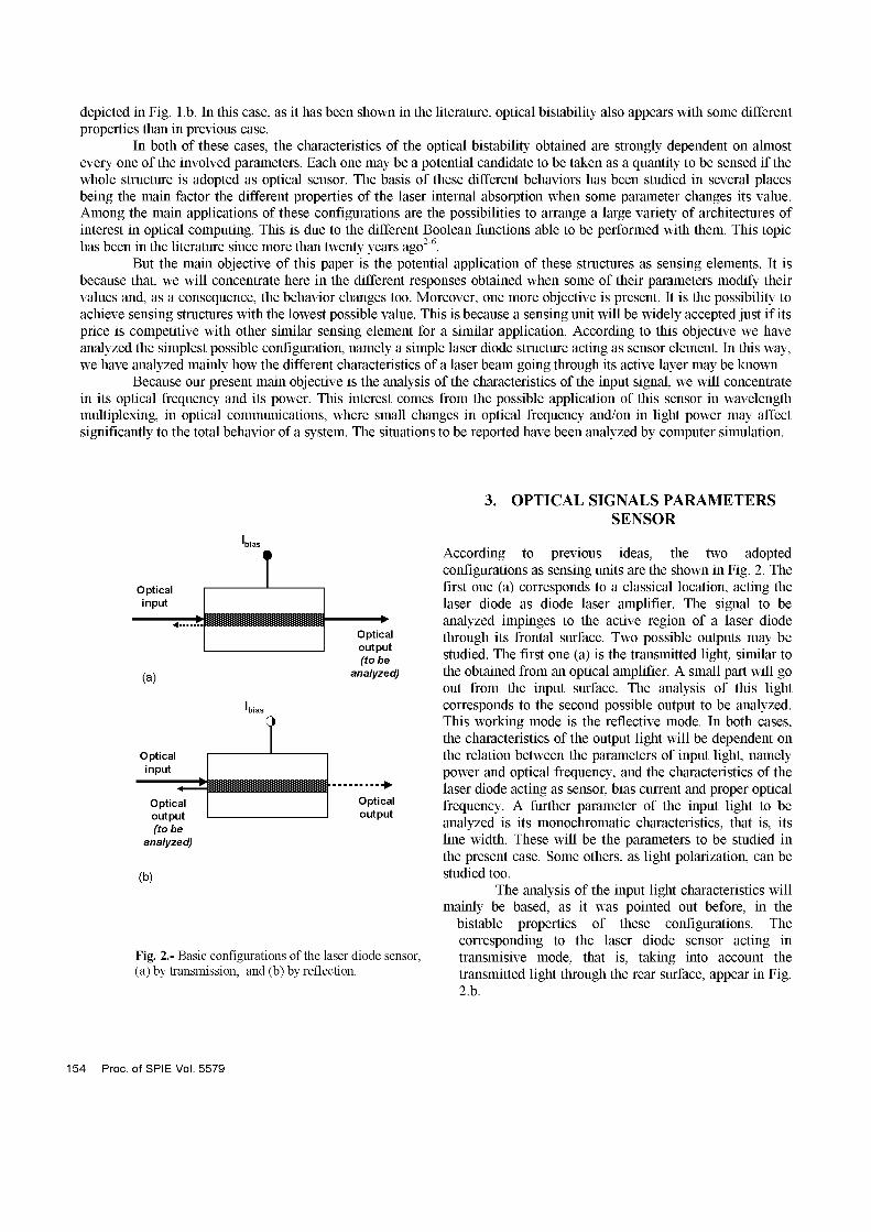
3. OPTICAL SIGNALS PARAMETERS SENSOR
Optical input
(a)
Optical input
Optical output (tobe
analyzed)
Optical output (tobe
analyzed)
O
Optical output
(b)
Fig. 2.- Basic configurations of the laser diode sensor, (a) by transmission, and (b) by reflection.
According to previous ideas, the two adopted configurations as sensing units are the shown in Fig. 2. The first one (a) corresponds to a classical location, acting the laser diode as diode laser amplifier. The signal to be analyzed impinges to the active region of a laser diode through its frontal surface. Two possible outputs may be studied. The first one (a) is the transmitted light, similar to the obtained from an optical amplifier. A small part will go out from the input surface. The analysis of this light corresponds to the second possible output to be analyzed. This working mode is the reflective mode. In both cases, the characteristics of the output light will be dependent on the relation between the parameters of input light, namely power and optical frequency, and the characteristics of the laser diode acting as sensor, bias current and proper optical frequency. A further parameter of the input light to be analyzed is its monochromatic characteristics, that is, its line width. These will be the parameters to be studied in the present case. Some others, as light polarization, can be studied too.
The analysis of the input light characteristics will mainly be based, as it was pointed out before, in the
bistable properties of these configurations. The corresponding to the laser diode sensor acting in transmisive mode, that is, taking into account the transmitted light through the rear surface, appear in Fig. 2.b.
154 Proc. o fSPIE Vol. 5579
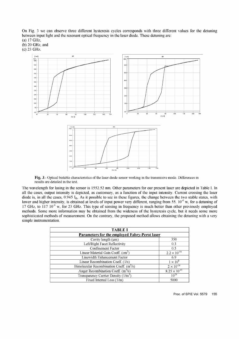
On Fig. 3 we can observe three different hysteresis cycles corresponds with three different values for the detuning between input light and the resonant optical frequency in the laser diode. These detuning are: (a) 17 GHz, (b) 20 GHz, and (c) 23 GHz.
6]
/ ,
[ y
XV
_
20 40 100 120 140 154 20 40 20 140 154
[1 e
„ o
6 ] XV
[1 e - 6 ]
O 1C O 1 O 1 O 1 5
Fig. 3.- Optical bistable characteristics of the laser diode sensor working in the transmisive mode. Differences in results are detailed in the text.
The wavelength for lasing in the sensor is 1552.52 nm. Other parameters for our present laser are depicted in Table I. In all the cases, output intensity is depicted, as customary, as a function of the input intensity. Current crossing the laser diode is, in all the cases, 0.945 1 .̂ As it possible to see in these figures, the change between the two stable states, with lower and higher intensity, is obtained at levels of input power very different, ranging from 55. 10"6 w, for a detuning of 17 GHz, to 117 10"6 w, for 23 GHz. This type of sensing in frequency is much better than other previously employed methods. Some more information may be obtained from the wideness of the hysteresis cycle, but it needs some more sophisticated methods of measurement. On the contrary, the proposed method allows obtaining the detuning with a very simple instrumentation.
TABLE I Parameters for the employed Fabry-Perot laser
Cavity length (nm) Left/Right Facet Reflectivity
Confinement Factor Linear Material Gain Coeff. (cm2)
Linewidth Enhancement Factor Linear Recombination Coeff. (1/s)
Bimolecular Recombination Coeff. (mVs) Auger Recombination Coeff. (nrVs) Transparency Carrier Density (l/m3)
Fixed Internal Loss (1/m)
350 0.3 0.5
2.2 xlO"16
6.9 l x l O 8
2xl0"1 6
8.25 x 10"41
10M
5000
Proc. ofSPIEVol. 5579 155
[1 e-3] XV
0.02 L J i i i L__ 192,888 193 193,1 193,2 193,312
[1 B1 2]
193 ,047 193 ,06 193 ,08 193,1 193 ,12 193 ,143
[ 1 8 1 2 ]
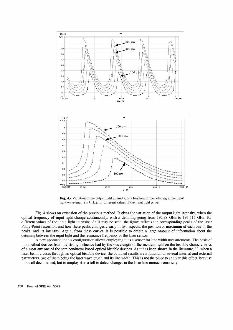
Fig. 4.- Variation of the output light intensity, as a function of the detuning in the input light wavelength (in GHz), for different values of the input light power.
Fig. 4 shows an extension of the previous method. It gives the variation of the output light intensity, when the optical frequency of input light change continuously, with a detuning going from 192.88 GHz to 193.312 GHz, for different values of the input light intensity. As it may be seen, the figure reflects the corresponding peaks of the laser Fabry-Perot resonator, and how these peaks changes clearly in two aspects, the position of maximum of each one of the peaks, and its intensity. Again, from these curves, it is possible to obtain a large amount of information about the detuning between the input light and the resonance frequency of the laser sensor.
A new approach to this configuration allows employing it as a sensor for line width measurements. The basis of this method derives from the strong influence had by the wavelength of the incident light on the bistable characteristics of almost any one of the semiconductor based optical bistable devices. As it has been shown in the literature,6"8, when a laser beam crosses through an optical bistable device, the obtained results are a function of several internal and external parameters, two of them being the laser wavelength and its line width. This is not the place to analyze this effect, because it is well documented, but to employ it as a toll to detect changes in the laser line monochromaticity.
156 Proc. ofSPIE Vol. 5579
The employed configurations are the same ones as the employed before. We have analyzed the transmissive mode because it has a better possibility to adapt to a conventional structure. The reflective mode may be employed to and the results should be very similar.
[1e
550
500
450
400
350
300
250
200
150
100
50
6] XV
/ /
> ,*̂ H
! 1 1 1 1
>*--t * -
X
/ y
1 0 1 3 3 3 A 0 5
[1e-
a o
6]
0 7 0 8 3 9 3 1 3
^J
(a)
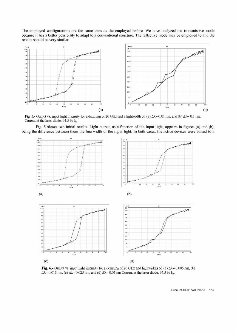
Fig. 5.- Output vs. input light intensity for a detuning of 20 GHz and a lightwidth of (a) Ak= 0.01 nm, and (b) Ak= 0.1 nm. Current at the laser diode: 94.5 % 1 .̂
(b)
Fig. 5 shows two initial results. Light output, as a function of the input light, appears in figures (a) and (b), being the difference between them the line width of the input light. In both cases, the active devices were biased to a
/ /
J-̂
^
s
I II 1
,M
,„-+* ^ /
**+^ t * * ^ *
r !
^^**
(a) (b)
[1e
500
400
6] XV
1 [1e 6]
(c)
[19
£50
sao
300
•ISO
100
6] XV
1 0 2
[1e 6]
(d)
Fig. 6.- Output vs. input light intensity for a detuning of 20 GHz and lightwidths of (a) Ak= 0.005 nm, (b) AX= 0.015 nm, (c) AX= 0.025 nm, and (d) AX= 0.05 mn Current at the laser diode, 94.5 % 1 .̂
Proc. ofSPIEVol.5579 157
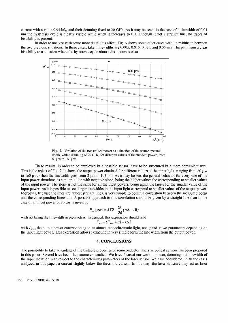
current with a value 0.945x1th and their detuning fixed to 20 GHz. As it may be seen, in the case of a linewidth of 0.01 nm the hysteresis cycle is clearly visible while when it increases to 0.1, although it not a straight line, no traces of bistability is present.
In order to analyze with some more detail this effect, Fig. 6 shows some other cases with linewidths in between the two previous situations. In these cases, taken linewidths are 0.005, 0.015, 0.025, and 0.05 nm. The path from a clear bistability to a situation where the hysteresis cycle almost disappears is clear.
[1 e-6] XV
2 - 1 0 20 30 40 SO 60 70 80 90 103
ne-3] AX(nm)
Fig. 7.- Variation of the transmitted power as a function of the source spectral width, with a detuning of 20 GHz, for different values of the incident power, from 80 (iwto 160 \iw.
These results, in order to be employed in a possible sensor, have to be structured in a more convenient way. This is the object of Fig. 7. It shows the output power obtained for different values of the input light, ranging from 80 |jw to 160 |jw, when the linewidth goes from 2 pm to 103 pm. As it may be see, the general behavior for every one of the input power situations, is similar: a line with negative slope, being the higher values the corresponding to smaller values of the input power. The slope is not the same for all the input powers, being again the larger for the smaller value of the input power. As it is possible to see, larger linewidths in the input light correspond to smaller values of the output power. Moreover, because the lines are almost straight lines, is very simple to obtain a correlation between the measured poear and the corresponding linewidth. A possible approach to this correlation should be given by a straight line than in the case of an input power of 80 |jw is given by
PoJpw) = 380-^(AA-15) ¿o
with AX being the linewitdh in picometers. In general, this expression should read
with Pmo„ the output power corresponding to an almost monochromatic light, and ¿"and rtwo parameters depending on the input light power. This expression allows extracting in very simple form the line width from the output power.
4. CONCLUSIONS
The possibility to take advantage of the bistable properties of semiconductor lasers as optical sensors has been proposed in this paper. Several have been the parameters studied. We have focused our work in power, detuning and linewidth of the input radiation with respect to the characteristics parameters of the laser sensor. We have considered, in all the cases analyzed in this paper, a current slightly below the threshold current. In this way, the laser structure may act as laser
158 Proc. ofSPIE Vol. 5579
amplifier of the input light. The obtained results show the reality of our proposal. Large changes are obtained in the output power, when some changes appear in the input light. We have proposed just an analytical expression for the last considered case: the one concerning linewidth. But similar expression could be obtained for previous cases as variation in the input power or in detuning. Expression as the one shown above allows an easy calibration of the possible meters based in this optical sensor.
ACKNOWLEDGMENTS
This work was partly supported by CICYT, grant TIC2003-04309, and CAM "Comunidad Autónoma de Madrid", grant FPI- Formación de Personal Investigador.
REFERENCES 1. S. Suzuki et al., "An Experiment on High-Speed Optical Time-Division Switching". Journal of Lightwave
Technology, vol. 4, pp. 894-99 (1986). 2. Drew. N. Maywar and Govind P. Agrawal, "Transfer-Matrix Analysis of Optical Bistability in DFB Semiconductor
Laser Amplifiers with Nonunifor Gratings", in IEEE Journal of Quantum Electronics, Vol. 33, No. 11, pp. 2029-2037. November 1997.
3. P. Pakdeevanich and M. J. Adams, "Measurements and Modeling of Reflective Bistability in 1.55|jm Laser Diode Amplifiers", in IEEE Journal of Quantum Electronics, Vol. 35, No. 12, pp. 1894-1903. December 1999.
4. M. J. Adams, R. Wyatt, "Optical Bistability in Distributed Feedback Semiconductor Laser Amplifiers", in IEE Proceedings Pt. J Optoelectronics, Vol. 134, No. 1, pp. 58-63. February 1987.
5. Zeqi Pan, Hongchin Lin, and M. Dagenais, "Switching Power Dependence on detuning and current in bistable diode laser amplifiers", in Appl. Phys. Lett. Vol. 58, No. 7, pp. 687-689. February 1991.
6. G. Mourat, N. Servagent and T. Bosch, "Optical Feedback Effects on the Spectral Linewidth of Semiconductor Laser Sensors Using Self-Mixing Interference", IEEE Journal on Quantum Electronics, Vol. 34, 9, pp. 1717-1721. September 1998.
7. N. Servagent, T Bosch and M. Lescure, "A laser displacement sensor using the self-mixing effect for modal analysis and defect detection". IEEE Trns. Instrum. Meas., vol. 46, pp.847-850, 1997.
8. Ana P. González-Marcos, J. A. Martín-Pereda and A. Hurtado, "Wavelength Monitoring with Semiconductor Laser Amplifiers", SPIE Vol. 5502. Second European Workshop on Optical Fibre Sensors, pp. 508-511 (2004)
Proc. ofSPIEVol. 5579 159