Embed Size (px)
Citation preview

Science & Global Security, 1990, Volume 2, pp.59-78Photocopying permitted by license onlyReprints available directly from the publisher@ 1990 Gordon and Breach Science Publishers S.APrinted in the United Stares of America
Laser Brightness Verification
T.H. Braid, A. De Volpi, C.L. Herzenberg, G.R. Ringo,and G,S. StanfordaLimits on the brightness of ground-based lasers appear to be straightforward to defineand, at high power and with cooperation, to monitor for verification of possible arms-
control treaties. We suggest using potential brightness defined as (beam power). (beamdiameterf/tr.(wavelengthfas the appropriate parameter to limit. Actual brightness is
quite dependent on atmospheric conditions. The complexities of on-site monitoring and
space-based lasers are discussed.
ONE CLASS of directed-energy weapon under development for attackingstrategic missiles and military satellites in flight involves bright lasersbeamed from earth to space or space to space. As is the case for other directed-energy weapons, lasers designed to intercept missiles or warheads can be usedin principle during any phase of trajectory: boost, coasting, or re-entry.Ground-based lasers can be used directly for the terminal phase and indirect-ly, with space-based mirrors, to reach earlier portions of the launch trajectory.In both cases, the beam would have to be directed through part of the earth'satmosphere, which would result in significant and variable attenuation anddefocusing. Although space-based lasers would not suffer such atmosphericlosses, the development of these systems could involve some testing in or
through the atmosphere.Proposals have been made for a treaty to curtail development and testing
of bright lasers above some threshold power below the brightness required forballistic-missile defenses (BMD) and anti satellite (ASAT) uses! In order to
a. The authors are all physicists employed by the Argonne National Laboratory, Argonne, IL60439, USA. The opinions expressed here are not necessarily those of the Laboratory or the USDepartment of Energy. All inquiries about this paper should be directed to G.R. Ringo.

60 Braid et a/.
assess technological and procedural capabilities for verification of laserbrightness, we first define brightness and then examine the factors that affectits role as a measure of laser-weapon capabilities. We discuss the characteris-tics of sources of laser light and evaluate the technology and the complexitiesassociated with the monitoring of laser beams.
It is assumed for the purposes of this analysis that quantitative limits onlaser-beam brightness could be negotiated, that in-country monitoringsupplemented by on-site inspection could be utilized for verification, and thatother information from national technical means (NTM) and perhapsprelaunch satellite inspection would be available. We assume, however, thatinspection of large lasers closely enough to fully disclose details of theirtechnology would be considered unacceptably intrusive.
We believe that, in the near term, space-based surveillance and otherNTM and human intelligence sources are not sufficient by themselves to giveconfidence in threshold limits. For example, satellite optical surveillance oftest sites could be blocked by clouds. Although clouds would also complicatetests of phase-compensation schemes and of general problems of beamtransport, useful tests could be carried out below cloud level, where most ofthe transport problems occur.
In order to minimize the number of facilities that would be subject tocontinuous monitoring, certain protocols would have to be developed in atreaty. We assume that all facilities that could produce laser beams above ahigh-level power threshold averaged over 1 second would be banned. Militaryresearch and development facilities that have laser power levels above anegotiated lower threshold would have monitoring stations installed nearby.
There would also have to be provision for challenge inspection of unde-clared facilities that are large enough to contain high-powered lasers. In somecases, if it were impossible to agree on a thorough internal inspection of thefacility, monitoring stations could be put in place around it at the request ofthe inspecting party.
LASER BRIGHTNESS
We believe the key variable for control of lasers as weapons is brightness B,
Laser Brightness Verification 61
which in this article is defined to be PD2f(n).,2) where P is the power of a laser,
D is the diameter of the beam at or near the source, and )., is the wavelength
of the emitted radiation.. We will use SI units, in which case brightness is in
watts per steradian. As will be made clear later, B is potential brightness
rather than actual brightness. The latter can vary from point to point across
a beam and is greatly complicated by effects of the atmosphere.
Potential brightness could best be monitored by permanent stations placed
within about 1 kilometer of sites where large lasers are tested in the atmo-
sphere. As will be seen below, brightness limits of the order of 1021 watts per
steradian would prevent applications to long-range ( > 1,000 kilometers)
destruction of missiles.. Much more restrictive limits would be needed to
prevent their threatening satellites.A conceivable drawback to using potential brightness as a limit is the
possibility that some peaceful application of powerful lasers might be devel-
oped that did not require complete coherence. In this fairly remote circum-
stance it might be desirable to negotiate an exemption.
Damage Caused by Laser Beams
Lasers are of interest for ballistic-missile defenses (BMD) primarily because
they offer the possibility of producing beams of electromagnetic radiation with
enough power density to be damaging to missiles 1,000 kilometers or more
from the source.Damage is dependent on the energy density that can be delivered in a
short time L1t. Tens of seconds will work. One tenth of a second is roughly the
optimum: longer times permit significant cooling hence require more energy
(but less power); shorter times would reqirire extreme power densities, which
might degrade the beam propagation or damage the laser.2 The integrated
energy fluence F in J m-2 that can be produced by a laser of power P, using a
* It has been pointed out to us by R.L. Garwin that this fonnula would lead to anunderestimate of the fluence in the important central area of the spot in the focal plane bya factor of tf/4 in cases of ideal propagation. We agree with Garwin, but in view of the factthat the APS report has become a standard reference and that this fonnula gives anapproximate average brightness out to the first diffraction-limited null, we think that theAPS definition is an acceptable (if arbitrary) basis for a treaty definition of potentialbrightness. See APS Study (reference 2).
~:,,~..~~
62 Braid et a/.
mirror of diameter D to focus radiation on a target a distance RT away, is
limited by diffraction to approximatel~
F = ~~ (1)nRi).z
Using the expression for brightness given earlier, we see
F = ~B (2)Ri
Since Lit and R~ are usually constrained by the target, B becomes the most
important free parameter determining a laser's ability to inflict damage. Forconcreteness, if Lit = 0.1 seconds, and we take the fluence necessary to destroy
hardened targets to be 10-1,000 MJ m-z* and the target distance to be 1,000
kilometers, we get B to be 1020-1022 watts per steradian.
It should be noted that BLit would be a reasonable quantity to limit. It is
probably what would be measured by a monitor in any case, since Lit is a
relatively easy quantity to measure. The distinction is not great.
The wavelength of the laser is also important. Atmospheric transmission
(see figure 1) probably limits it to greater than 0.4 microns for ground-based
lasers. The difficulty of finding suitable reflectors probably limits it to greater
than 0.2 micro~ even in space. Since the spot size goes as ).2/Dz, the difficulty
of deploying very large mirrors limits the largest wavelengths that could be
considered. Thus 20 microns appears to be about the upper limit!
For our purposes we will take the diameter D to be that of the beam at
the point where it starts upward. There could be circumstances where the
diameter of the space mirror is more important, but for the rough calculations
we are doing the difference is not of major significance.
* For illustration, 100 MJ m-2 will melt a I-millimeter aluminum plate even if it reflects 99
percent of the incident radiation, provided that the radiation is delivered in less than 1second. See the APS study (reference 2).
C'."",

II
;"..,:.c,~;.,: ---
Laser Brightness Verification 63
100 ,90 ,,"
80 --HI)
70 rco~ 60.0; C~Q)E~ro"Q)6 Q 40 -H P absorption.= Ozone absorption
30 ---Aerosol absorption
20 Rayleigh scattering H.p10 All scattering: ). > 0.8 microns, aerosols dominate
00.4 0.5 0.6 0.7 0.8 0.9 1.0 1.1 1.2 1.3 1.4 1.5 1.6 1.7
Wavelengthmicrons
Figure 1: Atmospheric transmission under typical clear conditions of constituents as a functionof wavelength
Source: APS Study Group, Reviews of Modern Physics, 59, p.S1 (1987)
Brightness Umits
From the above calculations it appears that a brightness cap of around 1 ~1
watts per steradian would constrain use of ground-based lasers for damaging
hardened missiles at distances greater than 1,000 kilometers in a time of 0.1
seconds. If it were decided to limit the use of lasers for discrimination between
decoys and warheads, a level lower by at least 100 times would probably be
necessary, since the ablation needed for discrimination by recoil is much
smaller than that necessary to produce damage.
Satellites are more vulnerable than ballistic missiles, however, and could
be attacked from the ground at distances as low as 150 kilometers. The
hardness of satellites is probably at least a factor of 10 lower than that of
missiles." If we take a hardness of 10 MJ m-2, then the maximum allowed
brightness would be roughly 1018 watts per steradian for pulsed ground-based
lasers. Another ASAT strategy is long (100 seconds) irradiation at lower power
that could overheat the whole satellite. Such long irradiations might be
* Satellites may have special vulnerabilities. We do not believe, however, that they are easyto blind by beams directed along their optical axes, because these axes are not very easy toobserve and are unpredictable.
c 64 Bra/d et a/.
practical because satellite trajectories are highly predictable and the satellites
are far apart. To limit this option an upper bound of 1016 watts per steradian
for the brightness would be needed for continuous-wave (CW) lasers and 1018
watts per steradian for pulsed lasers. For space-based lasers no meaningful
limits can be set, unless these lasers could somehow be prohibited from
arbitrarily close approaches to satellites.
The parameters entering in the calculations of the limits we have suggest-
ed are poorly defined in the published literature. This is particularly true for
hardness. Our limits are therefore very approximate. We have, however, tried
to make our suggestions for monitoring robust enough to tolerate large
variance in such limits.
Phase Compensation
The atmosphere can be a poor transport medium for coherent light beams.5
To be of practical size, ground-based lasers designed to attack objects in space
would probably need adaptive optics, which have been developed in the last 10
years for phase compensation. The details are complex, but for our purposes
the important facts are the following: to compensate for phase distortions in
the atmosphere, a probe beam is needed that traces the beam path backwards
through the atmosphere every few milliseconds and determines the effect of
atmosphere distortions on the beam phase. The source of this probe beam
could be something as simple as reflections of a sodium laser beam off the
layer of very-low-pressure sodium vapor in the upper atmosphere6 or as
complex as a satellite-based laser near one of the battle mirrors. As a result
of these adjustments to the beam at its source on the ground, the killing beam
would have a very complex phase structure. From point to point in a plane
normal to the beam the relative phase will not be uniform but will vary by a
significant fraction of a radian about every 10 centimeters and about every 10
milliseconds. It is clear that the higher the power of the laser, the more likely
it is to use phase compensation-because of thermal blooming,? which rises
with fluence as an important source of atmospheric irregularity, and because
the cost of a compensation system would be a small fraction of the total cost
of a high-power laser facility.

,,-
Laser Brightness Verification 65
Laser Power Requirements
We have estimated the required brightness of a BMD laser as 102°-1022 wattsper steradian for an illumination time of 0.1 seconds. If the opposing sidemade minimal efforts to harden its most vulnerable missiles, this range mightbecome 1 on-I 022 watts per steradian. Taking 31021 for illustrative purposes,and assuming). is 1 micron and D is 3 meters, we find a power requirementfor a phase-compensated laser ofl09 watts and an energy requirement of 108joules. For comparison, the large Nova lasers at the Lawrence LivermoreLaboratory, used for inertial confinement fusion experiments, produced about10. joules. The power and energy requirements for BMD lasers are consider-ably beyond the capabilities of any machines of which we are aware, and willin all probability require physically large lasers with large energy-storagecapability that would occupy several thousand cubic meters in a building, andfor BMD test purposes would need an access to the sky more than 10 squaremeters in area.
From the history of laser development we conclude that lasers of thecapability just mentioned can probably be developed within a few years. Themost interesting type perhaps is the free-electron laser (FEL), because itpromises high efficiency and a beam of controllable wavelength. It is not clear,however, whether it would be practicable to put a high-power FEL in a spacevehicle.
MONITORING LASER BEAMS
Ground-Based BMD Lasers
We believe the most practical method of ground-station monitoring of openbeams is to look at the beam radiation scattered by the aerosols normallypresent in the atmosphere. The scattered radiation would reveal the power inthe beam and, if necessary, give the beam diameter and the wavelength. Thepotential brightness is easily calculated from these parameters. The alterna-tive-direct sampling of the beam-would pose problems of intrusiveness,safety, and sampling accuracy. Inspection of the laser itself might be toointrusive.
We will assume that a monitor can be placed within a kilometer or so of
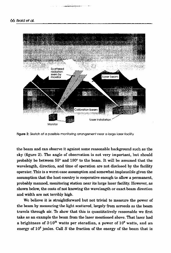
-"., ---
66 Braid et a/.
Monitor
Figure 2: Sketch of 0 possible monitoring arrongement near a large laser facility
the beam and can observe it against some reasonable background such as thesky (figure 2). The angle of observation is not very important, but shouldprobably be between 550 and 1800 to the beam. It will be assumed that thewavelength, direction, and time of operation are not disclosed by the facilityoperator. This is a worst-case assumption and somewhat implausible given theassumption that the host country is cooperative enough to allow a permanent,probably manned, monito~ station near its large laser facility. However, asshown below, the costs of not knowing the wavelength or exact beam directionand width are not terribly high.
We believe it is straightforward but not trivial to measure the power ofthe beam by measuring the light scattered, largely from aerosols as the beamtravels through air. To show that this is quantitatively reasonable we firsttake as an example the beam from the laser mentioned above. That laser hada brightness of 3-1021 watts per steradian, a power of 109 watts, and anenergy of 108 joules. Call S the fraction of the energy of the beam that is

'" --~~ Laser Brightness Verfflcation 67
scattered into 1 steradian in passing through 1 meter of air. This fraction is
dependent on the scattering angle, but within the range we are considering,
55° to 180°, the variation is generally less than a factor of two, and for
simplicity in this calculation of feasibility we will treat it as constant.S The
power density of the scattered radiation from this meter of beam length at the
monitor position thus becomes
I = ~ (3)MB R2
where P B is the power in the laser beam and R is the distance from the laser
beam to the monitor. A reasonable minimum estimate9 of S is 10-\ Taking
the area of the monitor lens as 10-3 square meters, one would then get a
signal of 10-7 watts at 1 kilometer from the beam, or 6.1011 photons per
second of I-micron wavelength. This is an easily detectable amount if the
background is low.
What is the background? The biggest potential source is scattered sun-
light. We approximate the scattering of sunlight by assuming S to be the same
as that of the laser beam. Then the scattered sunlight per cubic meter of air
is INS, where IN is the power density of sunlight in W m-2. The amount
reaching the position of the monitor would then be INS/r2 where r is the
distance from the cubic meter of air to the monitor. The background then will
be given by integrating this through a cone of solid angle .Q with apex at the
monitor and extending to the top of the atmosphere. The appropriate .Q is the
angle subtended at the monitor by the beam, of width w, taking the length as
1 meter since this whole calculation is done for 1 meter of beam length. Thus.Q = w/R2. Since the integration through the actual atmosphere of varying
density gets rather messy it is useful and conservative (because scattering per
gram of air generally decreases with altitude) to use an equal-mass constant-
density atmosphere model. We then get for the power density of the scattered
sunlight at the monitor position

-'":":, ~
68 Braid et al.
IMs = INS.QL = ~~ (4)R2
Here L is the distance along the line of sight of the monitor to the top of theatmosphere. If the monitor were looking straight up, L would be 8 kilometers.A more reasonable guess at the angle, 20° above horizontal, would give an Lof 23 kilometers. The ratio of the signal from the beam and that from thescattered sunlight is then
~ =-2-- (5)IMs INwL
For the reference laser w = 3 meters, and taking IN as 1,300 W m-2, the ratiofor L = 23 kilometers is 11-which seems ample. However there are, of course,
several complications. First we have implicitly assumed that the sunlight isscattered at more than 45°. If one is looking more directly at the sun thebackground could rise considerably. Also there could be brightly lit clouds inthe background. Most important, we are interested in monitoring lasers ofmuch less power than 109 watts. Therefore we discuss in the following sectionsmethods of enhancing signal-to-background ratio.
The worst-case situation for monitoring purposes would be an ASAT laser,because of the relatively lower power required for this mission. We considerthe cases of both a pulsed laser and a continuous laser.
Pulsed Lasers
Assume in this case that neither the wavelength nor the beam direction isknown, and the ASAT laser's brightness and power are about 10-3 of thoseconsidered for the BMD laser. Here it will be necessary that the detector be atwo-dimensional array of roughly 200 x 200 sensitive elements. One directionwill be used to scan the region of the beam for about 50w meters. The otherdirection will be a scan in wavelength achieved by a dispersing element,perhaps simply a prism. The wavelength range covered should be as narrowas it can be and still be sure to encompass the laser wavelength, in order to

~ Laser Brightness Verification 69
maximize dispersion. If there is literally nothing known of the wavelength,
several arrays may be needed: it is undesirable to cover more than a 2-to-l
ratio of wavelengths in one array, as this will adversely affect the signal-to-
background ratio.The signal associated with detection of a laser pulse consists of high
output from the elements that span the width of the beam in the row corre-
sponding to the laser wavelength. The background is given automatically by
the adjacent elements at nearby wavelengths. For this one could take sets of
elements at the same place in the position scan as the laser signal but at a
wavelength on each side of the laser's wavelength, and interpolate to the laser
wavelength (figure 3). The combination of dispersal in wavelength and careful
background subtraction should enhance the signal-to-background by a factor
of thousands-enough to offset the factor of 10-3 reduction in signal intensity
going from a BMD-capable to an ASAT-capable laser. The apparatus required
to do the electronic analysis is fairly similar to existing optical multichannel
analyzers:o
Continuous LasersAs noted above, in ASAT mode, a possible tactic is to use a laser of lower
power than is needed for a pulsed irradiation and keep it on the target for 10
seconds or more. This tactic is available because even a low-altitude satellite
would be in sight for that length of time, and there would probably be no
competing targets. In this case, flux rather than fluence is the appropriate
parameter, and we estimate a flux equal to the black-body radiation from a
surface at the melting point of aluminum (about 200 kW m-2) would be a
possible limit. This would correspond to a brightness oflij16 watts per steradi-
an, a power of 100 kilowatts (assuming a 3-meter mirror and 10-micron
wavelength),. and a satellite distance of 200 kilometers. Using the methods
given above, this would in turn give a scattered beam in clear air (100-
kilometer visibility) of 310-3 W m-2 scattered radiation. The infrared back-
ground from the ground at 10 microns (the worst case) would be about 10 W
* This assumes that the spot can be held to about 1 meter (or 1 arcsecond pointingaccuracy) on the satellite. This is not a trivial task but is within atmospheric turbulence1imi ts.

--_:::;"R;::~ ~--"
70 Braid et al.
I.. -so w/R .\
1 Aofthe monitored
A laser
R = reduction factor in the optical system
Figure 3: System for enhancing signal-to-background ratio for measurements on medium-
power lasers
m-2 for a 10-micron band. Clearly a very narrow wavelength selection would
be needed to detect the scattered laser light, and the monitor should not look
at the ground. Radiation from clouds, however, can be comparable, and they
may be hard to avoid (although heavy cloud cover is apt to discourage
operations of the monitored laser).If the wavelength were known within a few percent, the two-dimensional
scan of figure 3 combined with a high-resolution dispersing instrument-a
grating, for example-that matched the display might permit detection but
this is not guaranteed. Another tactic that might be useful would be to take
advantage of the long time of operation to use very-high-resolution Fourier-
transform spectroscopy.ll This could give wavelength resolution as high as 1
part in 105, with corresponding background suppression. The background is

;';";, -~~
Laser Brightness Verification 71
given accurately by this technique also, and can be subtracted to exhibit thesignal. There will probably be a loss of position discrimination however, andthis will cost a factor of the order of 30 in signal-to-background ratio.
While the two suggested techniques have been available for some time, we(
are proposing uses that will very possibly be near their limits. It wouldobviously be necessary to have tests in realistic situations to demonstratetheir feasibility.
In intermediate cases, less heroic measures should do. For example, if oneknows the wavelength of the laser to be monitored, a custom-made interfer-ence filter with a transmission band width of 10-3 microns may suffice. Suchfilters are considerably cheaper and simpler to use than the other apparatuswe have discussed in this section.
Another advantageous relaxation of our worst-case assumptions would beto station the monitor about 50 meters from the laser's directing mirror sothat it would look along the beam at an angle of say 1750 to the beam. Thiswould gain in two ways: first, the signal-to-background ratio would be muchbetter, and second, the calibration beam could be shone along a path in nearlythe same air as the monitored beam. Also, for monitoring CW lasers, we mayhave considerably underestimated the hardness of satellites, especially thoseyet to be put into orbit. For example, the long irradiation periods we havebeen discussing allow time for the satellite to react, turning its least vulnera-ble side to the laser.
Calibration of the Monitors
Since scattering is essentially all due to aerosols, which vary highly from hourto hour, it would be necessary to calibrate this scattering near the time ofobservation of the beam. This can be done by observing the scattering from alow-power (about 1 watt) laser beam a meter or two away from the detectorand directed at the same angle to the monitor's line of sight as the beam fromthe large laser. To detect this modest scattered radiation from a low-powerlaser, the laser must be run for perhaps a minute, and to suppress backgrounda narrow filter must be used. This is simple because the wavelength of thecalibrating laser is known well. The measurement will be useful even if thewavelength is different from that of the large laser being monitored, because

..,:::... ~--- ~
72 Braid et a/.
aerosol scattering is not strongly wavelength dependent in general!2 (Thereare, however, regions [for example, around 10 microns] where there is a strongdependence, and serious efforts must be made to match the wavelength within1 percent or so to get even 10-percent accuracy.)
It will be necessary to know or measure the width w of the beam beingmonitored and to know its distance from the monitor. We assume the latterwill be obvious from the installation of the monitor. The angular width of thebeam can be measured by the monitor, but it requires at least a one-dimen-sional scan-which could well be necessary anyway. The angular width andthe distance, of course, determine w. It is also straightforward to measure thepulse duration in simple cases. In the worst case, in which there is a pulsed,moderate-powered laser, as discussed above, there would be complications ifthe time of firing were not announced. This would require the stored datafrom the array to be erased approximately every 0.01 seconds if no laser pulsewere detected. H one was, the next O.Oln seconds of data from the portion ofthe array near the laser signal would have to be stored, and the pulse lengthmeasured this way. None of this is a heavy strain on modem data handlingmethods, but it is an expense and must be considered.
Since the calibration beam is assumed to be as much as a kilometer awayfrom the monitored beam, it would be desirable to check the relative scatter-ing in the relevant volumes of air with a lidar (radar using light instead ofradio waves) beam. Again, this is nearly an off-the-shelf technology, but itsuse would represent an increase in cost and complexity. The use oflidar wouldprobably be required only if the monitoring had to be done during a moderatedust storm. (A severe storm would very probably shut down the monitored
laser.)A possible complication in this scheme is that a high-power laser might
cause some of the scattering aerosols to evaporate, thus giving less scatteringthan a low-power beam. This point should be studied. If it proves significant,one remedy might be to focus the calibrating beam to a sharp point and lookat the scattering from there. A 1-watt laser can give a power density at itsfocal point of 100 GW m-2. By changing the focus, one could adjust the laserto match the beam of the monitored laser in power density. Pulse lengthmight also have to be matched. This whole problem may not be very impor-tant in the low-humidity weather at desert sites that would be favored for

Laser Brightness Verification 73,
ground-based laser weapons, because the aerosols would presumably not bevolatile.
Monitor Installation and Operation
The in-country monitoring equipment need not be placed just next to a laserfacility, but it should be within a few kilometers. It should operate in a"staring" mode, that is always sensitive to laser bursts, and it should not belimited to being only directed towards declared facilities. It will need a smallcalibrating beam within a few meters of the monitor. The equipment neededfor the complete station consists essentially of off-the-shelf items. No majordevelopment program is needed.
Conceivably such a station could be unattended, operating passively withsatellite link-up to transmit data to all treaty parties!3 Supplementaryverification could be achieved by on-site inspection during maintenance visitsto the monitoring station. Here is a case where the host country might bewilling to contribute to the cost of on-site monitoring in order to carry outlegitimate laser tests that fall between treaty-limited brightness levels and alower threshold that requires no monitoring. However, unattended stationsmight be vulnerable to simple forms of cheating such as smoke screens andother methods of interrupting the path from the beam to the monitoringstation. NTM might not serve to deter these forms of deception because sometests could be conducted under cloud cover. Supplementary instruments andprocedures need to be considered to counter deception scenarios of significance.
As a confidence-building measure, the verification potential of ground-based laser brightness measurements could be evaluated in demonstrationexperiments with off-the-shelf equipment.
Space-based Lasers
Space-based lasers clearly pose very difficult monitoring problems. The mostsevere is that one must have a space vehicle that can get within a fewkilometers of the laser to be monitored. Given that, there is a possibility thatone could monitor the laser.
We will take the situation at 200 kilometers altitude for illustration. Herethe number of molecules per cubic meter Nm is 7.1-1015 and the scattering
'croC~
-~
74 Braid et al."0
GI.!
N
10 r---
a:>
a:>
~
(')-0 -00-
0- 0-
0_0
0 r---
r--- r---
r--- r---
a:>
a:> a:>
a:>
a:>
a:>
a:>
0-
'"" 0-
0- 0-
0- 0-
0- 0-0-
0- 0-
0- 0-
0-aG
l ~
~
~
~
~
~
~
~
~
~
~
~
~a.
1 1
0 '""Q
)'"
'"'0
-l-l
0 '"'l
0 ~
0
c 0
0 0
,..::.~
-'"'-v""""
"- Q
)'~
'" c
E
~..::
b ~
c~
C
:" 0
Q)
0 I
'"" " "
:::J -:n
0"
0 "U
).c
~'""
Q)
C
+-
V::1
0 cQ
) '"
0 0
c .Q
o~-
-00 -<
{ Q
) +
-o+-
"0 :Q
-l -l
"5 ~
E
~
"O"O
~
Q)
",,- _0
0"" Q
) Q
)O
'"0
..:: 0
-..::C
O>
+-"-
E'--'
0 c
'--' >
--§
Q)Q
-'0
::1 Q
) '§:
x:cE
Q)
>
"OE
E
-E
"0
O~
0",.2.§
"0 ";::
Q)
Q)
EE
";:: 0
0 -o..c
c<
{ o.c.c
0 0
-0::1:!:: 0
::10 0
C
0 ::1
00>
"~;;;-
0", c
Q)
-.=
<{
>-
0 -.=
-E
E
cO
cO.5.
E
-g 11-
~
Q) ro
E
1dj"2 u-
Q)
Q"~
Q
Q
f,.:]"
"0.:]"::10 ~
0
.£0>::1
-~E
I
-no", to
Q)U
J~
I
";:: C
<
{ 0>
{) I";::
'--' >
- I
'--' -E
c Q
) "E-""Q)
I;::;-"'
0Q
)o >
-'--'E
.Q)
0"0 0
-l 0
CQ
) '"
"'~
"5>
>
'" 0"5
>o.c
-10'"" '=
-10 Q
)a;a.
00 g<
{ Q
)"O
00 .oQ
)Q)
0Q)..Q
. O
(')Q
u-o Q
)",
~
0 0
~e;."O
<{
Z
0 ~
X"O
zc
<{
o...=E
~...=
~.Q
Q)
0>~
0
o~'""0
'""0G
I~
N
8 ~
"f
N
5 ~
Q)
~&
DD
D
0 ~
10
0 00.
~O
>
1 N
O
E
8~
d
c0
~
=~
m
'6'
c::i!;
~~
~
:!
!::: ,""5~
~
::;~
0 -~
0
0 o~
o.oc ~
IOa;
"6>0>
~
~
~
~
'" ~
o (')1
:!:: ~
Q
c 0.
...=-m
~
-N
'--'C
"I
0Q
) 0
-00.
~
't5' c
~0
+-
.Q
-c:"Q
) ~
"5
0.c
oc +
-+
-.o
~
0 -0
Q)
"I'"" '"'
~~
0
+-
-0 Q
) '"
'" -l.£;t=
.o ()
0a;
.c =
Q
0
EE
'" !:?:
Q)
0 -l
'"" 0
.Q
0 3
"=
a; Q
) "<
{>
- -Q
)~
<{"'~
>
'"
OD
0>
aJ '"
0 '"
0 ~
'"1
::J ~
aJ
0-", ()
~
U-Q
)O
Q)-l
"1 Q
) ;>
u-
O-l
Q)
<{
~
~
-.c '"
11- '>
0~
<
{E
c '--'
;>
0>'"
~;>
I-
.'"
"0 :I::
'" ;>
~
c
<{
~
c "0
0 0>
'" c
Q)
'" ~
-'
~
I- Q
) v
C
-c1:.
'"" o~
C
I- IO
O
~
c 0
<{""Q
).Q
>
~
t ~
."fi "0
"0 ~
"0
-g ~
0
~
"'00
I 0
szUJ(j)
C
C<
{ C
O
-l <
{ ~
-l
aJ.."'i
u- 0
~
0 0
u- 0
0'--'
11- u-
.O.
->
<{oo
z Z
<{Z
-UJ
~
<{
UJ-
Q)
GI
U»O
U
) U
)U)
U)
000
<{o
U)
000::a
a::) <
{ ~
::)
::)::) ::)
U)
::) U
)
0I-

,,;,-,-_c. ) I
Laser Brightness V
erification 75
"C
~
~~
..!c('4
C'-
0- 'J;
-a) a)
.C
... 0-
0- 0.
cia~
~
~
0.
0.0.
I ro::
'0
co ~
~
0-~
~
Q)
~.0
Q)
.0E
E
co
, .<
!? Q
) II?
C
0.>
0. 0-
0 Q
) 0
0: ~
"in "'.
z. co
ci::J
"to '"
0- ,
-.-0 ()
~
0--o.c
>-
coC(J)
Q)
e co
0 ~
~
t) ~
::?:
~E
"tiQ
) 0.1l)
Q)
(J) ~
i:ij
ro:: ~
.0
C
Q)Q
) co;,:.
E~
+
-""" 0-0)
.<!?o-
C
-o~c.
~o
o.~0
I()~~
:?:O
Q)ci
U':1=
Q)"
:Jco (/)
~.o
aco
'~N
'0:
.:J 0-
-."'co-0
0. Q
. ',~
i
() 0.
~
0-.-0.
"1 '"
~
0 ~
, c
~t:
,<\:Q
)Q)
+-
0- o~
(J) ~
u-~.o
2Q)~
./::Q
)C
O
-"oE
o()o
~00..0
-~
+-
Q)
.o0
'-' ~
.!!! E
0.
'<i)
+-
~
'" '"
~
"ti C
.0
~
~
C/).o
"000
.e: 0
0 ~
5~~
z o~
E
5,I-
0 0
.,;«:J
~
.I: <
') C
~
~
~
<
3.,
:!:: N
0
Q)
-~
,,§3..c "O
~~
~
5Q
.;':'Jl~~
Z
'"
-'./::-'"
E
~
'<i)
::; ~
Q
) §
~
-0 "
00.'!=
: :J-
E"
~'l::C
.Q)
"'0('4 cO
«c;",
0000.""0
~~
o Q
)C.Q
O)
E"$~
'O
c~
...
O.a:
"8 '6
"5 .Q
-0
'<i)
"t 0.
R
co 0
Ov
~
0 .
>00:
CO
J S
i ~
C
Jl
C
0. -',
~
0 t?
D..Q
) '6
oC.c
,-'E
"O>
-O)Q
)E
>
Q)+
=:J()O
-Q)
C-o~
~g2E
~~
ggo~~
-.J"'
o.Q
)E
-Q)cot?-o
,
Q)C
/)uo~=
~~
Q)-c:-'::
6~.2uQ
)o.3~~
(I)o~c:
..,'<:«0
O-.J
()(/) 0
0 Q
) ~
'.
0, -'
-' 0
+-
-'
"5 ()Q
):t:~.::~
~~
:--o.~"
11)0 g~
oQ)~
'Q
).<!?Q
)~~
011)...
="-Q
)"oQ)"$.l:O
)?:(/)u~
Q)
""'" E
C
'=
~
-' ()
Q)
0) 0
+-:>
.Et;"O
..,g::?:
C
0) &
~
~
I- ~
0
~'cQ
j ~
"tocoQ
)~~
;",~c~
iD"f
Cl
QI
~"$
« ~
=
?: O
)..Q
0 <
:.,-~
Q
) ...Q
) (I)
¥O
.Q
", 0
+-
m~
2:
"- .I:
T
Q)
~
0 'Q
; E
E
-'
~"'-
" +
- Q
) ~
;;:
C
:J 0
t; >
0 Q
)"tic:J.!!!~.cC
T
2Q)0
~
'" 15: Q
)"C
iD::?:,
~
C
~
0)00) ~
-, I
I- .Q
Q
) ~
"'"
.I: 1=
=
~
:Q
Q)
.Y.
"'~U
"5~g>
u~8Q
.coQ)
.!!1 §Q
)0:J U
CI--LIJ.!!!(/)
0 "=
+-nU
cO.""u-~
c...,...
'" v
0 Q
) +
- Q
) 0
I- o~
~.?Io~
fi+-:J'E
"'+=
, ~
""E«(!)~
",2Q.Q
)~0
(J) ::"~
::;Q.",O
Q)t;iD
o. "C
D-+
- ~
~
-Cc"'E
oQ
)::J
Ee:!2~
o"""oo- ~
_:t=
0 t;
0 c:3
0 .<
!? " E
-'
U
u 0
"'"'"t; Q
)Q).I:
-'Q)¥!Q
)OS
~c,.,.f;c.
lXI.o'Q
;~~
~S
O'6os;:~
°'(j)'>
~iD
.co:i!. 'Q
;u-:;uo5"00>
O.Q
00. 0';;:
Z
~
8 ~
~
«
¥! ~
:I:(J)
-+-
~-,"",
~::>
':J ,
:J .cC
o .."
Q).ci
'o~'
..,u..,..,C
U)°.c
.I:.,;z-u~o
,.1:0).1:.1:cu
o",':Jo -"<
i)0 00
"""c
~
C:-
(/)... ~
Q
) .Q
cD
-5 U
£
° =
Q
) .§
Q)
Q)
0 0.
o::J::J u:l:~
~(/)Q
)c>Q
):l:c:l::I:U
0 U
) 0
~
Z
~
u>
a: 00
co Q
)Zo
=
~
:J ~
~
-'-"-"-' w
Q)
N
=Q
)u-Q)Q
)
-~
~~
~
~,Q
."Q."
co""
~a~
~
~
~
tt
d..; N
:a -"-"--'
~~
N<
,)':1Il)-o"coo-~~
~.2
-"---
76 Braid et a/.
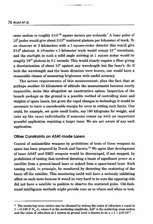
cross section is roughly 3.10-32 square meters per molecule." A laser pulse of
108 joules would give about 2.1014 s<:attered photons per kilometer of track. To
an observer at 3 kilometers with a I-square-meter detector this would give
2.106 photons. A 10-meter x I-kilometer track would occupy 10-3 steradians,
and the starlight in such a solid angle arriving at 1 square meter would be
roughly 1010 photons in 0.1 seconds. This would clearly require a filter giving
a discrimination of about 104 against any wavelength but the laser's. So if
both the wavelength and the beam direction were known, one would have a
reasonable chance of measuring brightness with useful accuracy.The severe requirements of this measurement, plus the fact that at
perhaps another 50 kilometers of altitude the measurement becomes nearly
impossible, make this altogether an unattractive option. Inspection of the
launch package on the ground is a possible method of controlling sizes and
weights of space lasers, but given the rapid changes in technology it would be
necessary to leave a considerable margin for error in setting such limits. One
could, for example, set quite small limits, say 100 kilograms for weight, and
take up the cases individually if someone comes up with an important
peaceful application requiring a larger laser. We are not aware of any such
application.
Other Constraints on ASAT -mode Lasers
Control of antisatellite weapons by prohibition of tests of these weapons in
space has been proposed by Durch and Garwin!4 We agree that development
of laser ASAT and BMD weapons would be discouraged, if not stopped, by
prohibition of testing that involved directing a beam of significant power at a
satellite from a ground-based laser or indeed from a space-based laser. Such
testing could, in principle, be monitored by detecting the scattering of the
beam off the satellite. This monitoring could well have a seriously inhibiting
effect on such tests because it would be very hard to be sure the opposing side
did not have a satellite in position to observe the scattered pulse. Old-fash-
ioned intelligence methods might provide cues as to where and when to look.
* The scattering cross section may be obtained by setting the index of refraction n equal to1 + (0.159,1,2 Nm b), where b is the scattering amplitude, 211h2 is the scattering cross sectionand the index of refraction at 1 micron at ground level is known to be n = 1 + 2.6710-4.

r
',"::'
Laser Brightness Verification 77
Tests at very-low-brightness levels with a cooperative satellite could
probably be concealed, but there would be serious questions as to how realistic
they were. It would be hard to be sure the focal properties of the laser system
would not be affected by a change of a factor of 106 or more in beam power.
Another constraint on ASAT (or BMD) use of lasers is to restrict the
construction of large lasers to regions with more than average cloud cover. No
rational government would make such an investment in weapons that could
be useless for weeks at arbitrary times!5
CONCLUSIONS
High-intensity lasers beamed through the atmosphere from known locations
constitute a technology that could be subject to agreed limitation. Our purpose
has been to explore the verifiability of such limitations, primarily by in-
country monitoring. Although the actual brightness would be difficult to
measure directly, we can determine with ground-based equipment the
potential brightness. Since this represents an upper bound to the energy
density deliverable by the laser, it would be an appropriate quantity to limit.
ACKNOWLEDGEMENTS
We are very grateful for help received from William Childs, Michael Dillon,
Richard Garwin, David Hafemeister, Ruth Howes, Tom Moog, Ron Ruby and
Frank von Hippel.
NOTES AND REFERENCES
1. J. Pike, "New Threshold Limits to Clarify the ABM Treaty," Federation of AmericanScientists FAS Public Interest Report, September 1987, pp.8-11.
2. The American Physical Society Study Group, "Science and Technology of DirectedEnergy Weapons," Reviews of Modem Physics, 59, pp.S1-S201 (1987).
3. Ibid. p.S34.
4. Ibid.

-;:1", --~-~--
78 Braid et al.-
5. Ibid.
6. E.K Hege, "A Means to Sharper Images", Nature, 328, 1987, p.198.
7. APS,1987.
8. R.H. Zerull, R.H. Giesse, S. Schwill, and K Weiss in Light Scattering by IrregularlyShaped Particles (New York: Plenum Press, 1979). See also the note by Prilutsky andFomenkova in this issue.
9. Ibid., together with W.L. Wolfe and G.J. Zissis, The Infrared Handbook (WashingtonDC: Office of Naval Research, Department of the Navy, 1985) pp.4-47.
10. J. W. Lewis, G.G. Yee, and D.S. Kliger, Rev. Sci. Inst!:, 58, 939 (1987).
11. R.J. Bell, in Kosta Tsipis, David W. Hafemeister, and Penny Janeway, eds., ArmsControl Verification (Washington DC: Pergamon-Brassey's, 1986), chapter 13.
12. Wolfe and Zissis.
13. Paul A Stokes, The National Seismic Station,SAND-81-2134, (Albuquerque, NewMexico: Sandia National Laboratory, June 1982); see also Paul A Stokes in KostaTsipis, David W. Hafemeister, and Penny Janeway, eds., Arms Control Verification,(Washington DC: Pergamon-Brassey's, 1986).
14. W.J. Durch in W.C. Potter, ed., Verification and Arms Control (Lexington,Massachusetts: Lexington Books, 1985), chapter 5; R.L. Garwin, "The Militarization ofSpace" testimony given before the Subcommittee on Arms Control, Oceans, Internation-al Operations and the Environment of the Senate Foreign Relations Committee, 20September 1982, pp.56-60.
15. H. Lee Buchanan, private communications.