Embed Size (px)
Citation preview
Large Scale Computer Modeling ofAerothermodynamics of Hypersonic Vehicle Composite
Constructions∗
Dimitrienko Yu.I.1, Koryakov M.N.1, Zakharov A.A.1
1Bauman Moscow State Technical University, Moscow, Russia
[email protected], [email protected], [email protected]
Abstract. The computational method for solving of couple air gas dynamics and internal heat transfer problems in
constructions of hypersonic vehicles is proposed. The method is based on iterative solution of three types of detached
problems: gas dynamics problem for ideal gas, viscous heat�conducting problem with full Navier�Stokes equations
for three�dimensional boundary layer and heat transfer equation for vehicle shell. Computer�aided software package
SIGMA that implements obtained algorithms and capable to perform calculations on high�performance computers
was developed. Results of modeling of flow over a hypersonic vehicle are presented and temperature fields for
adiabatic wall and with heat transfer between gas and wall are compared which shows the importance inclusion of
heat transfer computations in process of design of vehicle's head shield.
Keywords
Computational fluid dynamics, coupled thermal analysis, aerothermodynamics, heat transfer, hypersonic flows,
heat shield, parallel processing.
1 Introduction
Research in hypersonic aerodynamics to create high speed vehicle is conducted by organizations all over the world
[1, 2, 3, 4]. An effective way for such researches is a computer modeling, the success of which is determined not
only by the powerful of available computer systems, but also the ability of mathematical methods, algorithms and
software packages to solve complex problems associated with the largest possible number of physical phenomena and
with user friendly interface and the possibility of optimal loading of the all available resources of the supercomputer.
In the field of hypersonic aerodynamics universal numerical methods and algorithms that can adequately solve all the
emerging engineering problems do not exist, and therefore continue to work on the development of the new computing
technologies intensively.
The most often [4, 5] in computational methods for aerodynamics flows the temperature on vehicle surface are
solved using of either �cold wall� condition when heat flux and heat transfer coefficient to the wall are calculated
and then temperature of wall is calculated using these parameters or heat�isolated (adiabatic) wall condition when
heat transfer between wall and gas is absent. These approaches allow us to calculate either steady or known thermal
dynamic modes.
In this paper a new algorithm for solving the couple aerothermodynamics and internal heat transfer is proposed,
computer�aided software modules for the numerical implementation of this algorithm are developed and model con-
struction of high�speed vehicle is tested. The algorithm is based on a direct numerical simulation of gas dynamics
using the model of three�dimensional boundary layer [6] and a special algorithm for the numerical solutions of
the heat equation in the construction of the vehicle. The proposed methods use finite volume and finite difference
schemes of high order accuracy with low computational diffusion [7, 8, 9, 10]. The developed numerical methods
have the property of geometric parallelism, are implemented using cross�platform libraries and are designed to run on
supercomputers.
∗ [Optional thanks]: Work was funded by grants of the President of the Russian Federation research project no. MK-3150.2012.8and MK-3218.2013.8, supercomputer SKIF MSU ”Tchebychev” was used for computing tasks
Third International Conference "High Performance Computing" HPC-UA 2013 (Ukraine, Kyiv, October 7-11, 2013)
______________________________________________________________________________________________________________
-100-
2 Mathematical formulation of couple problem
Consider a nose of the vehicle construction, streamlined by hypersonic gas flow. We will consider three specific
domains: V1 � the domain of a high�speed inviscid nonconducting flow, which is described by the system of Euler
equations (1), V2 � the domain of the boundary layer, in which the full dynamic Navier�Stokes equations (2) are
solved for a viscous heat�conducting flow and V3 � the domain corresponding to the wall of the vehicle construction:
∂ρ
∂t+∇ · ρv = 0,
∂ρv∂t
+∇ · (ρv ⊗ v + pE) = 0,
∂ρε
∂t+∇ · ((ρε + p)v) = 0,
(1)
ρd
dt
(1ρ
)= ∇ · v,
ρdvdt
= −∇p +∇ ·Tv,
ρde
dt= −p∇ · v −∇ · q + Tv · ·∇ ⊗ vT ,
(2)
where ρ � the gas density, t � the time, v � the velocity vector, p � the pressure, E � the identity tensor, ε � the
total energy per unit volume, e � the internal energy per unit volume.
This system adds relations for the perfect gas, viscous stress tensor and heat flux vector:
p = ρBθ, ε = e +|v|2
2, e = cV θ, |v|2 = v · v, Tv = µ1(∇ · v)E + µ2(∇⊗ v +∇⊗ vT ), q = −λ∇θ,
where B � the individual gas constant, θ � the gas temperature, cV � the specific heat at constant volume, µ1 and
µ2 � the coefficients of viscosity, λ � the thermal conductivity of the gas.
The gas is assumed incompressible viscous (inviscid volume), so µ1 = −23µ2.
For the description of turbulent transport model is used Cebeci�Smith semi�empirical theory of turbulence [11, 12].
On the outer surface of the boundary layer, which is the interface between the movement of the inviscid (V1) and
viscous flow (V2), the following conditions for continuity are formulated:
[ρ] = 0, [v] = 0, n ·Tv · τI = 0, [θ] = 0. (3)
Here [ ] � jump features on the outer surface of the boundary layer.
In the domain V3 the heat equation is considered:
ρscs∂θ
∂t= λs∆θ, (4)
where λs � the thermal conductivity of the solid, ρs � density of the solid, cs � specific heat.
The boundary conditions on the solid surface, which is the interface of the gas and solid domains, are as follows:
−λ∇θg · n + εgσθ4max = −λs∇θs · n + εsσθ4
w, [θ] = 0, (5)
where θw � the temperature of the solid surface (equal to the temperature of the gas on the surface), θmax � the
maximum temperature into the boundary layer, ∇θs � the temperature gradient on the solid wall from the construction,
∇θg � temperature gradient from the boundary layer of the gas, εg and εs � the emissivity of the heated gas and
solid surface respectively, σ � Stefan�Boltzmann constant.
Physical and chemical transformations of the wall material (ash, melting, thermal decomposition) are not taken into
account.
At the inner surface of the vehicle construction the thermal insulation condition is imposed:
∇θ · n = 0. (6)
Third International Conference "High Performance Computing" HPC-UA 2013 (Ukraine, Kyiv, October 7-11, 2013)
______________________________________________________________________________________________________________
-101-
The initial condition for the equation (4) is:
t = 0 : θ = θ0. (7)
3 Development of methods for solving the couple problem
To solve the couple problem formulated above suggest the following method: cycle by �slow� time t̄ = t/t0corresponding to the heat transfer in the body shell is entered, where t0 � the characteristic time of heating the
construction. Inside this cycle �fast� time τ = t/tg is entered, where tg � the characteristic establishment time of the
flow. For every fixed moment of slow time t̄n heat flux through the wall qs = −λs∇θs · n is generally unknown is
supposed to be fixed, then for the boundary conditions on the solid surface (5) is considered only the first:
−λ∇θg · n = qs + εsσθ4w − εgσθ4
max, (8)
and the gas dynamics equations (1) and (2) are separated from the heat equation (4) one step at slow time.
According to the model three�dimensional boundary layer [6], the inviscid flow equation (1) and viscous flow (2)is also separated. The solution of (1) is found in whole flow domain V1∪V2 with the slip wall boundary condition
v ·n = 0. Next the solution of (2) in the V2 is calculated over the fast time to the steady flow with the conditions for
the solid surface: v = 0 and (8). Thereafter, a transition to the next step t̄n+1 of the slow time occurs.
Numerical finite�difference methods MacCormack and TVD second�order approximation [5, 7, 8, 9], as well
as finite�volume method RKDG [10] are used for the solutions of the systems of differential equations (1)�(2).MacCormack method is the easiest and fastest, but it has the largest computational diffusion. TVD scheme requires
large amounts of computer time, it has low computational diffusion, but it is very sensitive to the quality of the mesh.
RKDG method has the advantage of TVD-scheme, and it allows calculation on non-smooth meshes, but it is the
slowest.
The viscous components are approximated using the implicit difference schemes with splitting method by the
spatial directions [13], which are solved by the Thomas algorithm.
The heat flux qs,n+1 on the solid surface at the next (n+1)-time step is calculated using a special method proposed
in [14]. According to this method, at the first the numerical solution of the heat equation (4) is calculated for the
principal part of the heat flow ∇θs · n in the normal direction to the heated surface (heat flows in the tangent plane
∇θs · τI are ignored) and only with the second boundary condition (5) (with a predetermined surface temperature).
Then, after the dimensionless heat equation (4) with the initial and boundary conditions (5)�(7) takes the form:
∂θ̄
∂t̄= Fo
∂2θ̄
∂x̄2, 0 < x̄ < 1; x̄ = 0 : θ̄ = θ̄w; x̄ = 1 :
∂θ̄
∂x̄= 0; t̄ = 0 : θ̄ = 1; (9)
where Fo =λst0
ρscsH� the Fourier number, H � shell thickness, θ̄ =
θ
θ0, θ̄w =
θw
θ0� dimensionless temperatures,
x̄ =x
H� dimensionless coordinate shell thickness.
To solve the one�dimensional heat conduction problem (9) we use the step by step method with the implicit
difference scheme:
θ̄n+1k − θ̄n
k
∆t̄= Fo
θ̄n+1k+1 − 2θ̄n+1
k + θ̄n+1k−1
∆x̄2, θ̄n
0 = θ̄w, θ̄nK = θ̄n
K−1. (10)
where K + 1 � the number of nodes through the shell thickness. The system of algebraic equations obtained from
equation (10) is solved by the Thomas algorithm.
4 Description of developed software
The developed software modules included in the software package SIGMA [15] have been applied to solve the couple
supersonic and hypersonic gas flow and internal heat transfer problems in the solution domains of complex curved
shapes. SIGMA allows capture combined (internal and external) flow problems, calculation of pre�unknown shock
waves form and the jump conditions, laminar and turbulent flows, explore the transient unsteady mode. SIGMA
includes three�dimensional geometric modeling module, which allows to generate a wide range of geometric shapes;
module, which allows to set properties, parameters and initial conditions; adaptive mesh generator (preprocessing
Third International Conference "High Performance Computing" HPC-UA 2013 (Ukraine, Kyiv, October 7-11, 2013)
______________________________________________________________________________________________________________
-102-
components); the solver (processor) and the visualization tools (post�processor). Each module is the detached cross�
platform software, implemented using C++ and the ability to create extensions. Most of the iterative procedures
for the mesh generation and the solver implemented using OpenMP 2.0 and MPI libraries by means of geometric
decomposition.
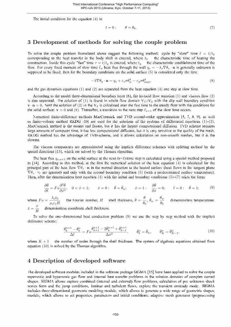
Preprocessor module has a graphical interface that allows you to create the solution domain visually. The domain
is constructed from a set of initial hexahedral blocks (primitives) by their combining and subsequent deformation. The
deformation is performed by changing of coordinates of the control points of the domain by entering them or reading
from a file. Control points of the domain are located on the boundary surfaces of the primitives, formed a regular
surface mesh and are the basis for the construction of linear or cubic spline surfaces. It is possible to generate a curved
blocks based on the geometry of surfaces, imported in the STL file format from solid modeling software, see figure 1.
In this case, functions for generation of the points in given sections and along the lines between the two specified
points on the surface are realized for the construction of regular mesh of control points on the imported surface.
Each block has the associated set of characteristics: the type of the initial condition in the block, the types of
boundary conditions, and the bounding box of the curved block in the computational and physical coordinates. On
the basis of the characteristics mesh generator distributes nodes and defines the appropriate parameters in them, see
figure 2.
Mesh generator creates the non�orthogonal block�structured grid and uses explicit form of the algebraic transfor-
mation, which refers to the lagrangian coordinate transformations of transfinite interpolation methods [8]. Additional
transformations of the grid are introduced to concentration the nodes near the boundaries. For certain types of curved
domains preprocessor is able to construct the O-grid blocks like in ANSYS ICEM CFD.
Figure 1. The construction of the solution domain for modeling of the outer flow ofperspective hypersonic vehicle: (left) loaded STL-geometry of the surface; (center)aided construction of curved blocks; (right) view of resulting domain.
Figure 2. Generated meshes: (left) for inviscid flow V1∪V2 domain; (center) forboundary layer V2 domain; (right) for V1∪V2 domain with boundary layer.
Solver allows doing the calculation to a certain point of time, saving the calculation results at specified intervals
and resumption of calculation from the saved state. Results can be output for the whole geometry of solution domain,
as well as for the certain sections and points.
5 The results of the numerical solutions
Figure 3�6 present the results of numerical simulation of hypersonic flow (M = 6) around the nose of the vehicle
model flying at the altitude of 15 km for the domain V1∪V2.
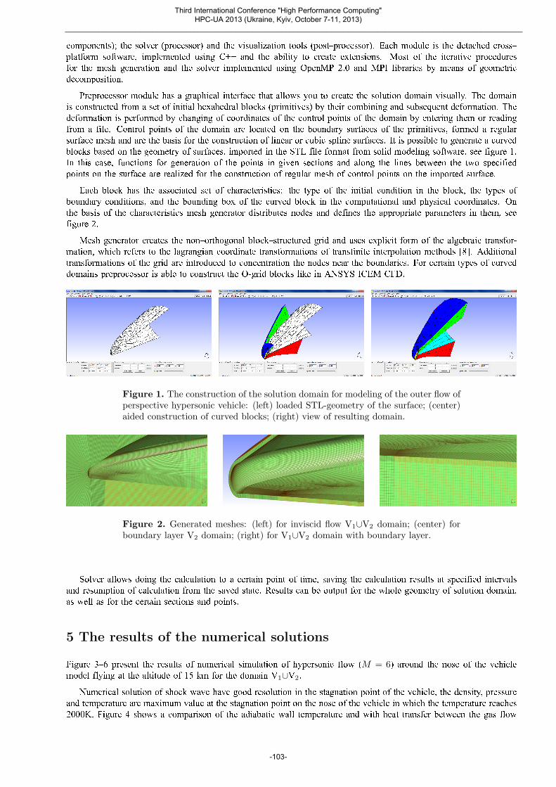
Numerical solution of shock wave have good resolution in the stagnation point of the vehicle, the density, pressure
and temperature are maximum value at the stagnation point on the nose of the vehicle in which the temperature reaches
2000K. Figure 4 shows a comparison of the adiabatic wall temperature and with heat transfer between the gas flow
Third International Conference "High Performance Computing" HPC-UA 2013 (Ukraine, Kyiv, October 7-11, 2013)
______________________________________________________________________________________________________________
-103-
and the shell in 50 seconds after the start of the calculation. In the second case, the average temperature on the surface
of the body is 25% lower than in the first, therefore inclusion of heat transfer computations is important aspect for
estimation of limiting mode of the vehicle and for heat�shield material selection.
Figure 3. Distribution of the parameters of the gas flow near the surface of hy-personic vehicle: (left) density ρ (kg/m3); (center) longitudinal velocity vz (m/s);(right) pressure p (Pa).
Figure 4. Temperature θ (K) distribution of the gas flow near the surface of hy-personic vehicle: (left) for the adiabatic wall; (right) for the heat transfer throughthe wall.
6 Conclusion
The computational method for solving of couple air gas dynamics and internal heat transfer problems in constructions
of hypersonic vehicles is developed. The software package SIGMA was written based on this method and makes
it possible to generate in semiautomatic mode regular adaptive grids in complex domains with curved boundaries,
to simulate transient and establishment processes and hypersonic high gradients flows with good quality. SIGMA's
algorithms have the property of geometric parallelism and are adapted to run on supercomputers. SIGMA was used
for performing numerical simulation of three�dimensional flow around the nose of the vehicle model. It is shown that
the inclusion of heat transfer computations allow to more accurately determine of temperature on the surface of the
vehicle.
Third International Conference "High Performance Computing" HPC-UA 2013 (Ukraine, Kyiv, October 7-11, 2013)
______________________________________________________________________________________________________________
-104-
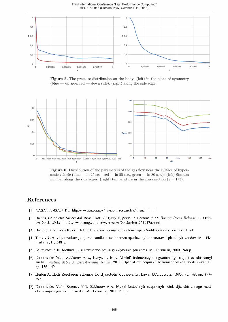
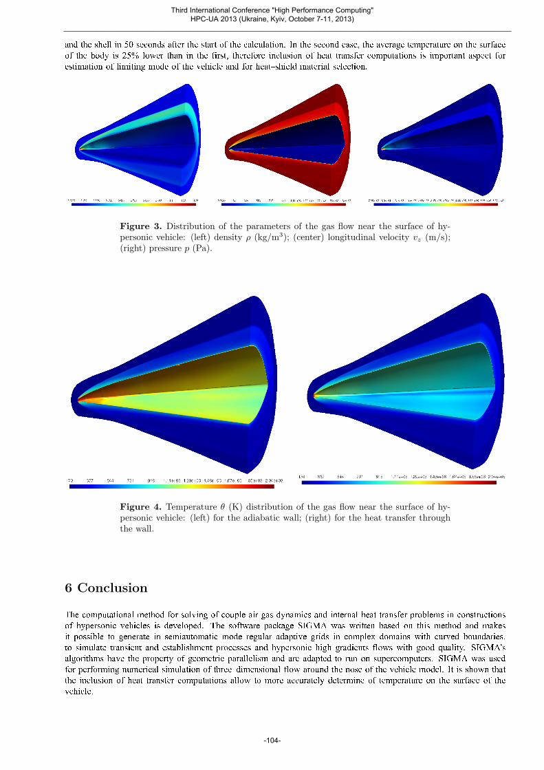
Figure 5. The pressure distribution on the body: (left) in the plane of symmetry(blue — up side, red — down side); (right) along the side edge.
Figure 6. Distribution of the parameters of the gas flow near the surface of hyper-sonic vehicle (blue — in 25 sec., red — in 55 sec., green — in 80 sec.): (left) Stantonnumber along the side edges; (right) temperature in the cross section (z = 1/3).
References
[1] NASA's X-43A. URL: http://www.nasa.gov/missions/research/x43-main.html
[2] Boeing Completes Successful Boost Test of HyFly Hypersonic Demonstrator, Boeing Press Release, 17 Octo-
ber 2005. URL: http://www.boeing.com/news/releases/2005/q4/nr 051017a.html
[3] Boeing: X-51 WaveRider. URL: http://www.boeing.com/defense-space/military/waverider/index.html
[4] Tirskiy G.A. Giperzvukovaja ajerodinamika i teploobmen spuskaemyh apparatov i planetnyh zondov. M.: Fiz-
matlit, 2011. 548 p.
[5] Gil'manov A.N. Methods of adaptive meshes in gas dynamic problems. M.: Fizmatlit, 2000. 248 p.
[6] Dimitrienko Yu.I., Zakharov A.A., Koryakov M.N. Model' trehmernogo pogranichnogo sloja i ee chislennyj
analiz. Vestnik MGTU. Estestvennye Nauki. 2011. Special'nyj vypusk �Matematicheskoe modelirovanie�,
pp. 136�149.
[7] Harten A. High Resolution Schemes for Hyperbolic Conservation Laws. J.Comp.Phys. 1983. Vol. 49, pp. 357�
393.
[8] Dimitrienko Yu.I., Kotenev V.P., Zakharov A.A. Metod lentochnyh adaptivnyh setok dlja chislennogo mod-
elirovanija v gazovoj dinamike. M.: Fizmatlit, 2011. 286 p.
Third International Conference "High Performance Computing" HPC-UA 2013 (Ukraine, Kyiv, October 7-11, 2013)
______________________________________________________________________________________________________________
-105-
[9] Razvitie metoda lentochno�adaptivnyh setok na osnove shem TVD dlja reshenija zadach gazovoj dinamiki /
Yu.I. Dimitrienko, M.N. Koryakov, A.A. Zakharov, Ye.K. Syzdykov. Vestnik MGTU. Estestvennye Nauki.2011. N 2. pp. 87�97.
[10] Cockburn B., Shu C.�W. Runge�Kutta Discontinuous Galerkin Methods for Convection�Dominated Problems.
Journal of Scientific Computing. 2001. Vol. 16. N 3, pp. 173�261.
[11] Cebeci T. Turbulence Models and Their Application. Horizons Pub., Long Beach, Calif. and Springer, Heidelberg,
2003.
[12] Cebeci T. Analysis of Turbulent Flows. Elsevier, London, 2003.
[13] Yanenko N.N. Metod drobnyh shagov reshenija mnogomernyh zadach matematicheskoj fiziki. Novosibirsk:
Nauka, sib. otd-ie, 1967. 197 p.
[14] Dimitrienko Yu.I., Efremov G.A., Chernyavsky S.A. Optimal Designing of Erosion�Stable Heat�Shield Composite
Materials. Int. Journal of Appl. Comp. Mat. 1997. Vol. 4. N 1, pp. 35�52.
[15] Dimitrienko Yu.I., Zakharov A.A., Koryakov M.N. Razrabotka programmnogo obespechenija dlja chislennogo
modelirovanija v zadachah giperzvukovoj ajerogazodinamiki perspektivnyh letatel'nyh apparatov // Programm-nye sistemy: teorija i prilozhenija : jelektron. nauchn. zhurn. 2012. V. 3, N 4(13), pp. 17�26.
Third International Conference "High Performance Computing" HPC-UA 2013 (Ukraine, Kyiv, October 7-11, 2013)
______________________________________________________________________________________________________________
-106-