Embed Size (px)
Citation preview
Language Distribution SystemIntegrus
en Operation manual

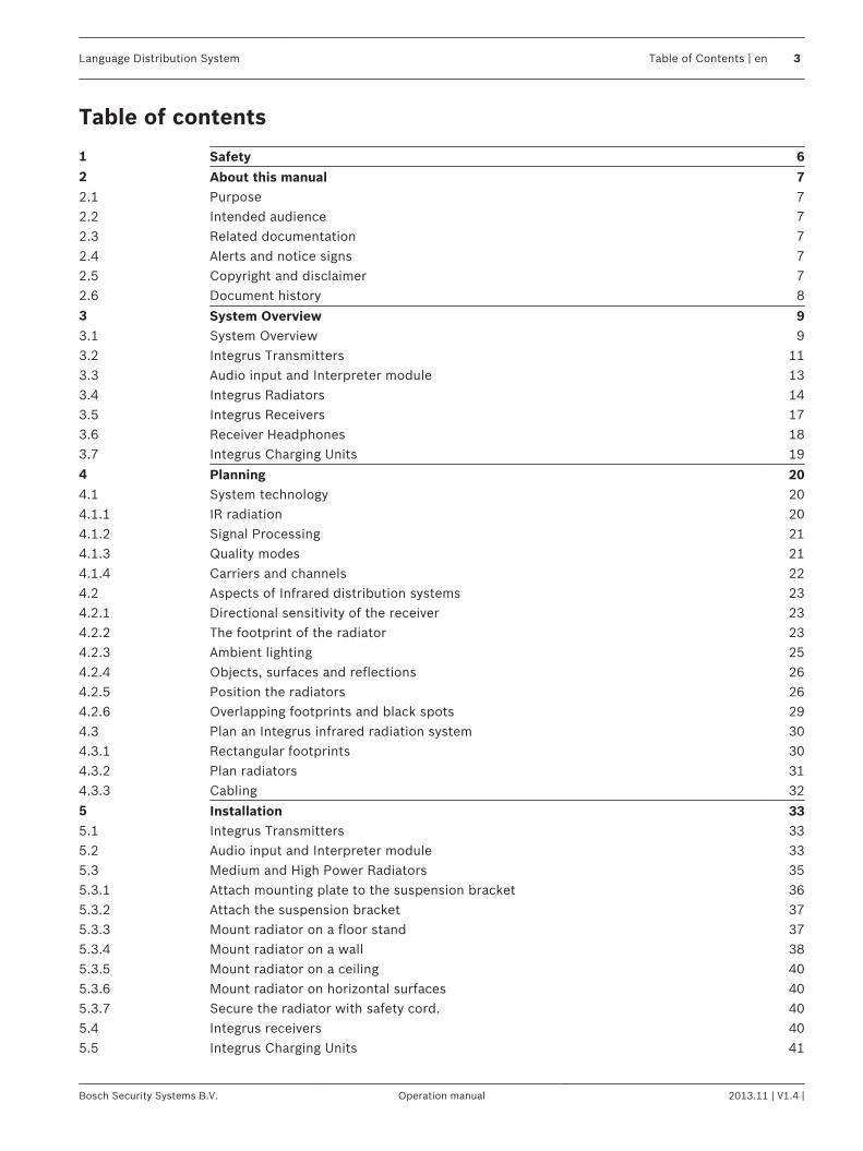
Table of contents
1 Safety 62 About this manual 72.1 Purpose 72.2 Intended audience 72.3 Related documentation 72.4 Alerts and notice signs 72.5 Copyright and disclaimer 72.6 Document history 8
3 System Overview 93.1 System Overview 93.2 Integrus Transmitters 113.3 Audio input and Interpreter module 133.4 Integrus Radiators 143.5 Integrus Receivers 173.6 Receiver Headphones 183.7 Integrus Charging Units 19
4 Planning 204.1 System technology 204.1.1 IR radiation 204.1.2 Signal Processing 214.1.3 Quality modes 214.1.4 Carriers and channels 224.2 Aspects of Infrared distribution systems 234.2.1 Directional sensitivity of the receiver 234.2.2 The footprint of the radiator 234.2.3 Ambient lighting 254.2.4 Objects, surfaces and reflections 264.2.5 Position the radiators 264.2.6 Overlapping footprints and black spots 294.3 Plan an Integrus infrared radiation system 304.3.1 Rectangular footprints 304.3.2 Plan radiators 314.3.3 Cabling 32
5 Installation 335.1 Integrus Transmitters 335.2 Audio input and Interpreter module 335.3 Medium and High Power Radiators 355.3.1 Attach mounting plate to the suspension bracket 365.3.2 Attach the suspension bracket 375.3.3 Mount radiator on a floor stand 375.3.4 Mount radiator on a wall 385.3.5 Mount radiator on a ceiling 405.3.6 Mount radiator on horizontal surfaces 405.3.7 Secure the radiator with safety cord. 405.4 Integrus receivers 405.5 Integrus Charging Units 41
Language Distribution System Table of Contents | en 3
Bosch Security Systems B.V. Operation manual 2013.11 | V1.4 |
6 Connection 426.1 Integrus Transmitters 426.2 Connect the DCN Next Generation system 426.3 Connect other external audio sources 436.4 Connect an emergency signal 446.5 Connect to another transmitter 456.6 Connect radiators 46
7 Configuration 487.1 Integrus transmitter 487.1.1 Overview 487.1.2 Navigate through the menu 497.1.3 Example 507.2 Setup the transmitter 517.2.1 Main menu 517.2.2 Set transmission (4A) 527.2.3 Set network mode (4B) 527.2.4 Set number of channels (4C) 537.2.5 Set channel quality and assign inputs to channels (4D) 547.2.6 Language list (4E) 557.2.7 Set channel names (4F) 557.2.8 Disable or enable carriers (4G) 567.2.9 View carrier assignments (4H) 567.2.10 Configure auxiliary inputs (4I) 577.2.11 Set sensitivity of the inputs (4J, 4K, 4L) 577.2.12 Enable / disable IR-monitoring (4M) 587.2.13 Enable / disable headphone output (4N) 587.2.14 Choose transmitter name (4O) 587.2.15 Reset all options to factory default values (4P) 597.3 Integrus Radiators 597.3.1 Set the output power selection switch 597.3.2 Set the delay switches 607.4 Determine the radiator delay switch positions 607.4.1 System with one transmitter 607.4.2 System with two or more transmitters in one room 637.4.3 Systems with more than 4 carriers and a radiator under a balcony 65
8 Testing 668.1 Integrus Transmitter 668.2 Integrus Receiver 678.3 Test the coverage area 67
9 Operation 699.1 Integrus transmitter 699.1.1 Start-up 699.1.2 View transmitter status 699.2 Integrus Radiators 699.3 Integrus Receivers 709.3.1 Normal operation 709.3.2 Storage of receiver 719.4 Integrus Charging Units 71
4 en | Table of Contents Language Distribution System
2013.11 | V1.4 | Operation manual Bosch Security Systems B.V.
10 Troubleshooting 7210.1 Fault messages 7210.2 Faultfinding guide 7310.3 Service requests 75
11 Maintenance 7612 Technical Data 7712.1 Electrical Data 7712.1.1 Overall system characteristics 7712.1.2 Transmitters and Modules 7712.1.3 Radiators and Accessories 7812.1.4 Receivers, Battery Packs and Charging Units 7812.1.5 Cables and connectors 8012.2 Mechanical Data 8112.2.1 Transmitters and Modules 8112.2.2 Radiators and Accessories 8112.2.3 Receivers, Battery Packs and Charging Units 8212.3 Ambient Conditions 8312.3.1 Overall system conditions 8312.4 Rules and Standards 8412.4.1 Overall system conformance 8412.5 Guaranteed rectangular footprints 8512.5.1 Metric values of radiators with hardware version higher than 2.00 8512.5.2 Imperial values of radiators with hardware version higher than 2.00 8712.5.3 Metric values of radiators with hardware version lower than 2.00. 8912.5.4 Imperial values of radiators with hardware version lower than 2.00. 91
Language Distribution System Table of Contents | en 5
Bosch Security Systems B.V. Operation manual 2013.11 | V1.4 |
SafetyPrior to installing or operating the products, always read the installation instructions insection Installation, page 33 and the Safety Instructions which are provided with the mainspowered products.
!Warning!
To prevent possible hearing damage, do not listen at high volume levels for long periods.
1
6 en | Safety Language Distribution System
2013.11 | V1.4 | Operation manual Bosch Security Systems B.V.
About this manual
PurposeThe purpose of this document is to provide information required for installing, configuring,operating, maintaining and troubleshooting an Integrus Language Distribution System.
Intended audienceThis document is intended for installers and users of an Integrus Language DistributionSystem.
Related documentation– DCN Next Generation operation manual. Refer to the product related information at:
www.boschsecurity.com
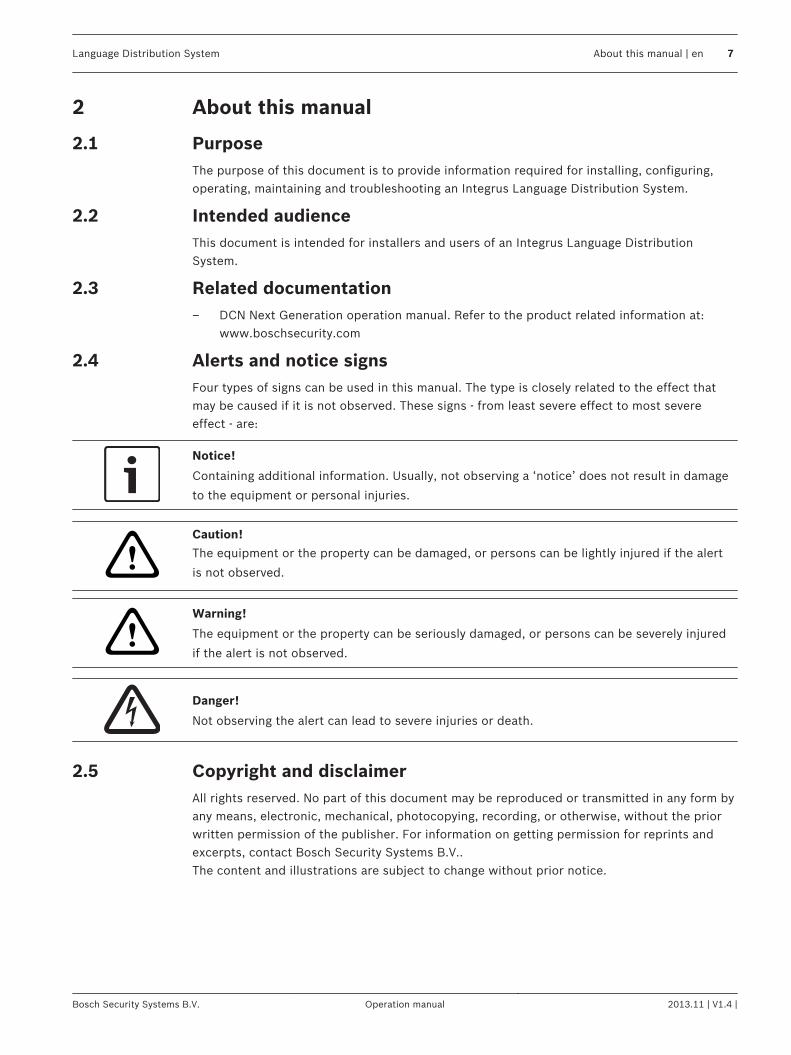
Alerts and notice signsFour types of signs can be used in this manual. The type is closely related to the effect thatmay be caused if it is not observed. These signs - from least severe effect to most severeeffect - are:
Notice!
Containing additional information. Usually, not observing a ‘notice’ does not result in damage
to the equipment or personal injuries.
!
Caution!
The equipment or the property can be damaged, or persons can be lightly injured if the alert
is not observed.
!Warning!
The equipment or the property can be seriously damaged, or persons can be severely injured
if the alert is not observed.
Danger!
Not observing the alert can lead to severe injuries or death.
Copyright and disclaimerAll rights reserved. No part of this document may be reproduced or transmitted in any form byany means, electronic, mechanical, photocopying, recording, or otherwise, without the priorwritten permission of the publisher. For information on getting permission for reprints andexcerpts, contact Bosch Security Systems B.V..The content and illustrations are subject to change without prior notice.
2
2.1
2.2
2.3
2.4
2.5
Language Distribution System About this manual | en 7
Bosch Security Systems B.V. Operation manual 2013.11 | V1.4 |
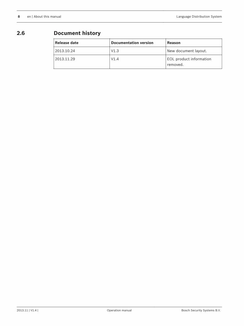
Document history
Release date Documentation version Reason
2013.10.24 V1.3 New document layout.
2013.11.29 V1.4 EOL product informationremoved.
2.6
8 en | About this manual Language Distribution System
2013.11 | V1.4 | Operation manual Bosch Security Systems B.V.
System Overview
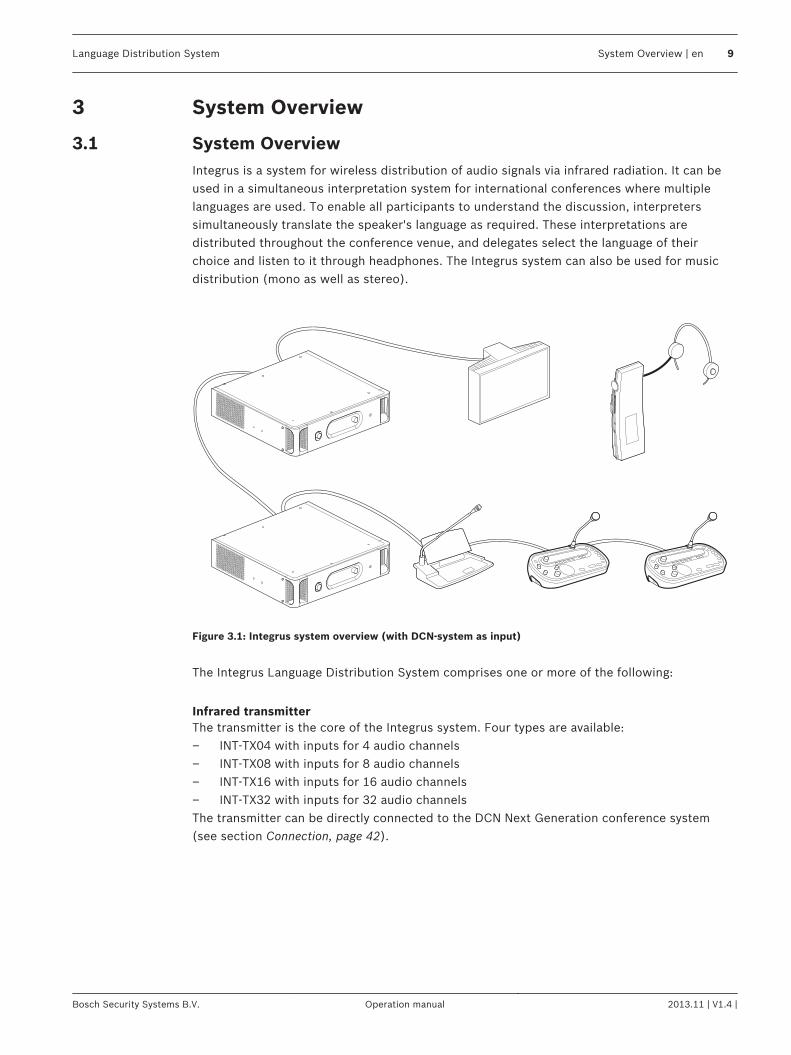
System OverviewIntegrus is a system for wireless distribution of audio signals via infrared radiation. It can beused in a simultaneous interpretation system for international conferences where multiplelanguages are used. To enable all participants to understand the discussion, interpreterssimultaneously translate the speaker's language as required. These interpretations aredistributed throughout the conference venue, and delegates select the language of theirchoice and listen to it through headphones. The Integrus system can also be used for musicdistribution (mono as well as stereo).
Figure 3.1: Integrus system overview (with DCN-system as input)
The Integrus Language Distribution System comprises one or more of the following:
Infrared transmitterThe transmitter is the core of the Integrus system. Four types are available:– INT‑TX04 with inputs for 4 audio channels– INT‑TX08 with inputs for 8 audio channels– INT‑TX16 with inputs for 16 audio channels– INT‑TX32 with inputs for 32 audio channelsThe transmitter can be directly connected to the DCN Next Generation conference system(see section Connection, page 42).
3
3.1
Language Distribution System System Overview | en 9
Bosch Security Systems B.V. Operation manual 2013.11 | V1.4 |
Audio input and Interpreter moduleThe audio input and interpreter’s module can be mounted in the transmitter housing toconnect the transmitter to a wide range of conference systems:– LBB 3422/20 Integrus audio input and interpreters module to connect to analogue
discussion and conference systems (such as CCS 900) or to LBB 3222/04 6-channelinterpreters desks.
Infrared radiatorsTwo radiators are available:– LBB 4511/00 medium-power radiator for small/ medium conference venues– LBB 4512/00 high-power radiator for medium/large conference venuesThe radiators can be mounted on walls, ceilings or floor stands.
Infrared receiversThree multi-channel infrared receivers are available:– LBB 4540/04 for 4 audio channels– LBB 4540/08 for 8 audio channels– LBB 4540/32 for 32 audio channelsThe receivers can operate with a rechargeable NiMH battery pack or with disposable batteries.Charging circuitry is incorporated in the receiver.
Charging equipmentEquipment is available for charging and storing 56 infrared receivers. Two versions areavailable:– LBB 4560/00 charging suitcase for portable systems– LBB 4560/50 charging cabinet for permanent systems
10 en | System Overview Language Distribution System
2013.11 | V1.4 | Operation manual Bosch Security Systems B.V.
Integrus TransmittersThe transmitter is the central element of the Integrus system. It accepts asymmetrical audiosources from a maximum of 32 external channels (dependent on the transmitter type) and canbe used with the DCN Next Generation conference system. It can also be used with analoguediscussion and interpretation systems (e.g. CCS 900 with up to 12 interpreter desks), or as astand-alone system distributing external audio sources.
Transmitter front view
32 4 51
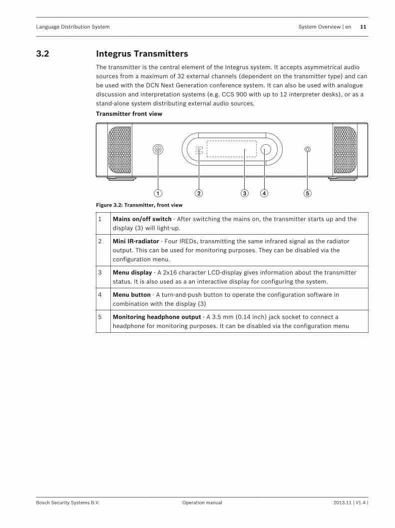
Figure 3.2: Transmitter, front view
1 Mains on/off switch - After switching the mains on, the transmitter starts up and thedisplay (3) will light-up.
2 Mini IR-radiator - Four IREDs, transmitting the same infrared signal as the radiatoroutput. This can be used for monitoring purposes. They can be disabled via theconfiguration menu.
3 Menu display - A 2x16 character LCD-display gives information about the transmitterstatus. It is also used as a an interactive display for configuring the system.
4 Menu button - A turn-and-push button to operate the configuration software incombination with the display (3)
5 Monitoring headphone output - A 3.5 mm (0.14 inch) jack socket to connect aheadphone for monitoring purposes. It can be disabled via the configuration menu
3.2
Language Distribution System System Overview | en 11
Bosch Security Systems B.V. Operation manual 2013.11 | V1.4 |
Transmitter rear view
1 3 5 7 9 11 13 15 17 19 21 23 25 27 29 31
0 2 4
4 5 62 31
8 10 12 14 16 18 20 22 24 26 28 30
Network1 2
1 2
6 97
53
8
4
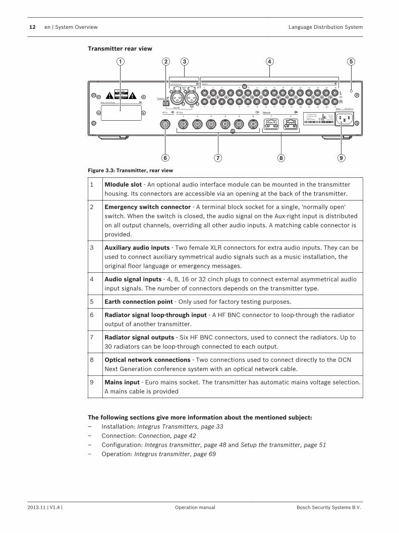
Figure 3.3: Transmitter, rear view
1 MIodule slot - An optional audio interface module can be mounted in the transmitterhousing. Its connectors are accessible via an opening at the back of the transmitter.
2 Emergency switch connector - A terminal block socket for a single, 'normally open'switch. When the switch is closed, the audio signal on the Aux-right input is distributedon all output channels, overriding all other audio inputs. A matching cable connector isprovided.
3 Auxiliary audio inputs - Two female XLR connectors for extra audio inputs. They can beused to connect auxiliary symmetrical audio signals such as a music installation, theoriginal floor language or emergency messages.
4 Audio signal inputs - 4, 8, 16 or 32 cinch plugs to connect external asymmetrical audioinput signals. The number of connectors depends on the transmitter type.
5 Earth connection point - Only used for factory testing purposes.
6 Radiator signal loop-through input - A HF BNC connector to loop-through the radiatoroutput of another transmitter.
7 Radiator signal outputs - Six HF BNC connectors, used to connect the radiators. Up to30 radiators can be loop-through connected to each output.
8 Optical network connections - Two connections used to connect directly to the DCNNext Generation conference system with an optical network cable.
9 Mains input - Euro mains socket. The transmitter has automatic mains voltage selection.A mains cable is provided
The following sections give more information about the mentioned subject:– Installation: Integrus Transmitters, page 33– Connection: Connection, page 42– Configuration: Integrus transmitter, page 48 and Setup the transmitter, page 51– Operation: Integrus transmitter, page 69
12 en | System Overview Language Distribution System
2013.11 | V1.4 | Operation manual Bosch Security Systems B.V.
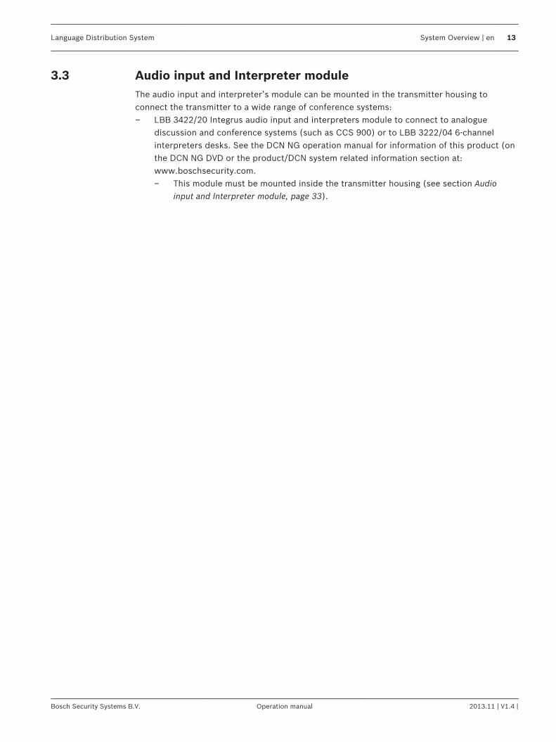
Audio input and Interpreter moduleThe audio input and interpreter’s module can be mounted in the transmitter housing toconnect the transmitter to a wide range of conference systems:– LBB 3422/20 Integrus audio input and interpreters module to connect to analogue
discussion and conference systems (such as CCS 900) or to LBB 3222/04 6-channelinterpreters desks. See the DCN NG operation manual for information of this product (onthe DCN NG DVD or the product/DCN system related information section at:www.boschsecurity.com.– This module must be mounted inside the transmitter housing (see section Audio
input and Interpreter module, page 33).
3.3
Language Distribution System System Overview | en 13
Bosch Security Systems B.V. Operation manual 2013.11 | V1.4 |
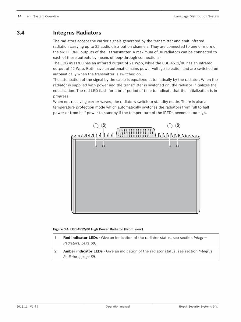
Integrus RadiatorsThe radiators accept the carrier signals generated by the transmitter and emit infraredradiation carrying up to 32 audio distribution channels. They are connected to one or more ofthe six HF BNC outputs of the IR transmitter. A maximum of 30 radiators can be connected toeach of these outputs by means of loop-through connections.The LBB 4511/00 has an infrared output of 21 Wpp, while the LBB 4512/00 has an infraredoutput of 42 Wpp. Both have an automatic mains power voltage selection and are switched onautomatically when the transmitter is switched on.The attenuation of the signal by the cable is equalized automatically by the radiator. When theradiator is supplied with power and the transmitter is switched on, the radiator initializes theequalization. The red LED flash for a brief period of time to indicate that the initialization is inprogress.When not receiving carrier waves, the radiators switch to standby mode. There is also atemperature protection mode which automatically switches the radiators from full to halfpower or from half power to standby if the temperature of the IREDs becomes too high.
1 21 2
Figure 3.4: LBB 4512/00 High Power Radiator (Front view)
1 Red indicator LEDs - Give an indication of the radiator status, see section IntegrusRadiators, page 69.
2 Amber indicator LEDs - Give an indication of the radiator status, see section IntegrusRadiators, page 69.
3.4
14 en | System Overview Language Distribution System
2013.11 | V1.4 | Operation manual Bosch Security Systems B.V.
3
2
1
4
5
6
7
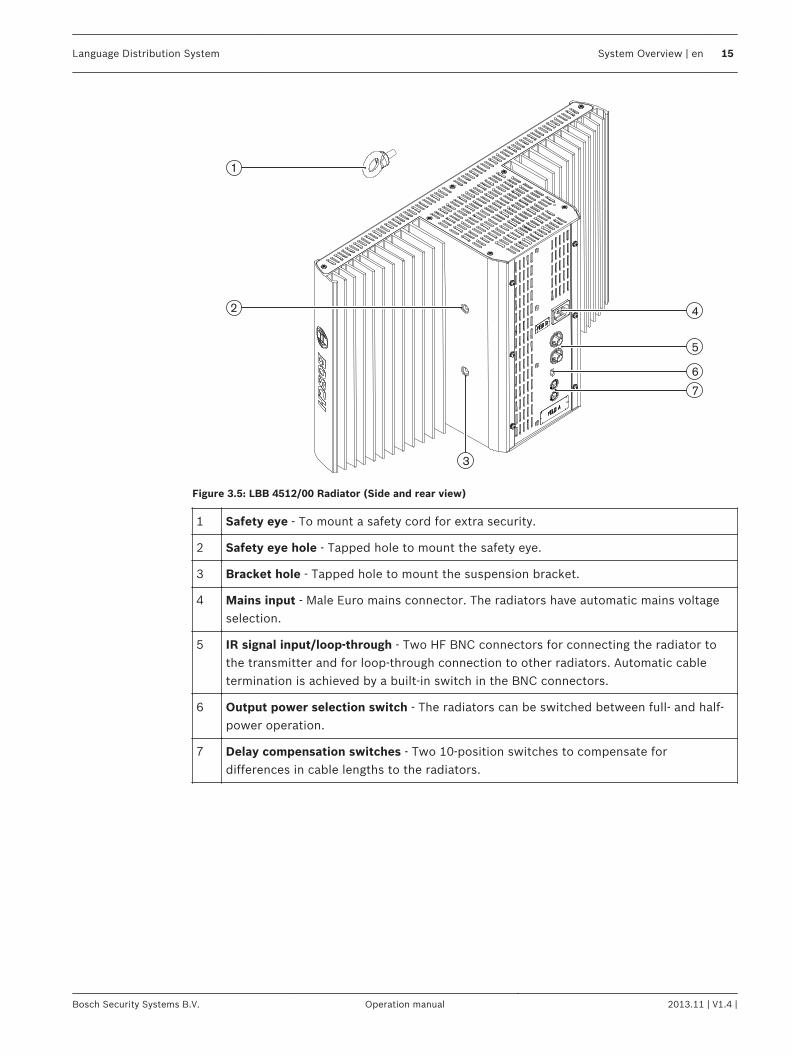
Figure 3.5: LBB 4512/00 Radiator (Side and rear view)
1 Safety eye - To mount a safety cord for extra security.
2 Safety eye hole - Tapped hole to mount the safety eye.
3 Bracket hole - Tapped hole to mount the suspension bracket.
4 Mains input - Male Euro mains connector. The radiators have automatic mains voltageselection.
5 IR signal input/loop-through - Two HF BNC connectors for connecting the radiator tothe transmitter and for loop-through connection to other radiators. Automatic cabletermination is achieved by a built-in switch in the BNC connectors.
6 Output power selection switch - The radiators can be switched between full- and half-power operation.
7 Delay compensation switches - Two 10-position switches to compensate fordifferences in cable lengths to the radiators.
Language Distribution System System Overview | en 15
Bosch Security Systems B.V. Operation manual 2013.11 | V1.4 |
4 2 4
3
3
5
5
1
6
7
6
7
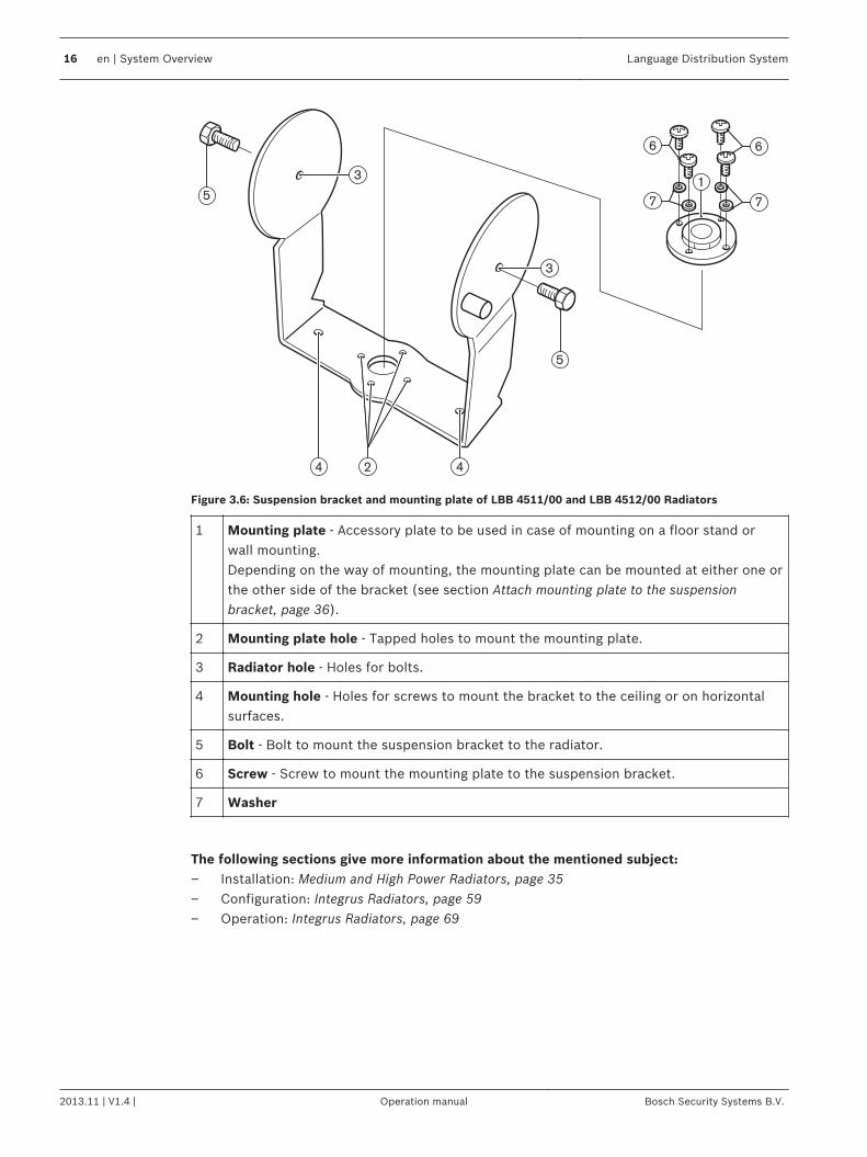
Figure 3.6: Suspension bracket and mounting plate of LBB 4511/00 and LBB 4512/00 Radiators
1 Mounting plate - Accessory plate to be used in case of mounting on a floor stand orwall mounting.Depending on the way of mounting, the mounting plate can be mounted at either one orthe other side of the bracket (see section Attach mounting plate to the suspensionbracket, page 36).
2 Mounting plate hole - Tapped holes to mount the mounting plate.
3 Radiator hole - Holes for bolts.
4 Mounting hole - Holes for screws to mount the bracket to the ceiling or on horizontalsurfaces.
5 Bolt - Bolt to mount the suspension bracket to the radiator.
6 Screw - Screw to mount the mounting plate to the suspension bracket.
7 Washer
The following sections give more information about the mentioned subject:– Installation: Medium and High Power Radiators, page 35– Configuration: Integrus Radiators, page 59– Operation: Integrus Radiators, page 69
16 en | System Overview Language Distribution System
2013.11 | V1.4 | Operation manual Bosch Security Systems B.V.
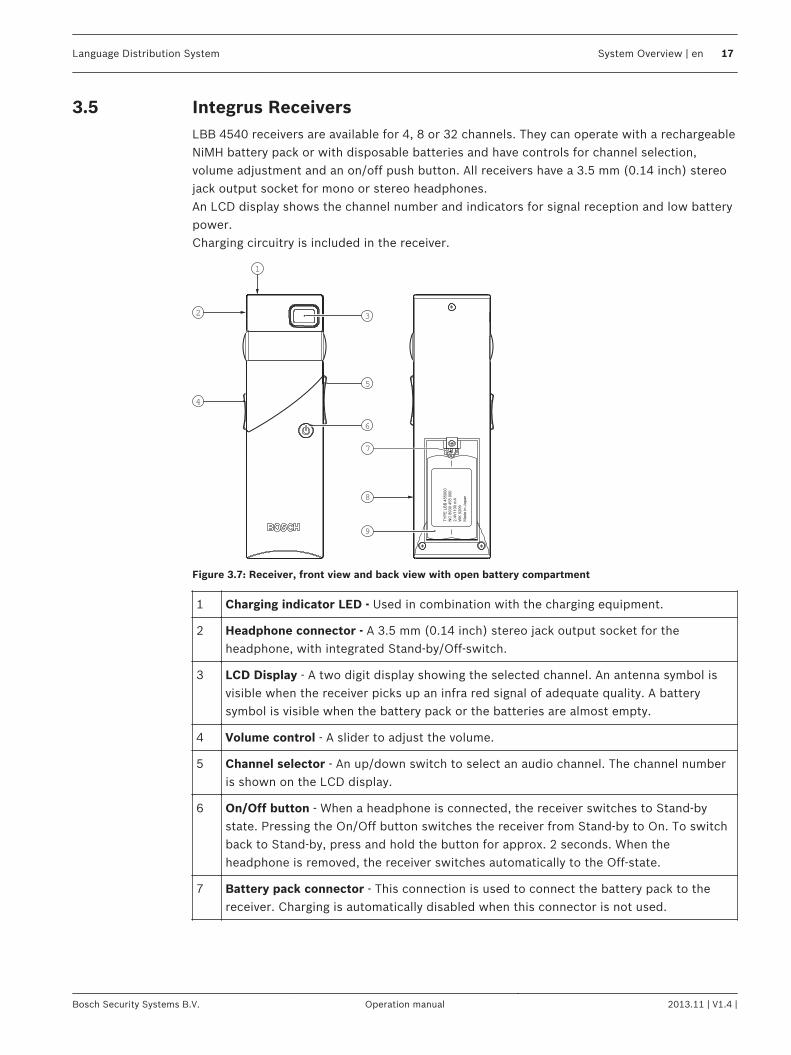
Integrus ReceiversLBB 4540 receivers are available for 4, 8 or 32 channels. They can operate with a rechargeableNiMH battery pack or with disposable batteries and have controls for channel selection,volume adjustment and an on/off push button. All receivers have a 3.5 mm (0.14 inch) stereojack output socket for mono or stereo headphones.An LCD display shows the channel number and indicators for signal reception and low batterypower.Charging circuitry is included in the receiver.
2
1
4
3
5
8
7
9
6
Figure 3.7: Receiver, front view and back view with open battery compartment
1 Charging indicator LED - Used in combination with the charging equipment.
2 Headphone connector - A 3.5 mm (0.14 inch) stereo jack output socket for theheadphone, with integrated Stand-by/Off-switch.
3 LCD Display - A two digit display showing the selected channel. An antenna symbol isvisible when the receiver picks up an infra red signal of adequate quality. A batterysymbol is visible when the battery pack or the batteries are almost empty.
4 Volume control - A slider to adjust the volume.
5 Channel selector - An up/down switch to select an audio channel. The channel numberis shown on the LCD display.
6 On/Off button - When a headphone is connected, the receiver switches to Stand-bystate. Pressing the On/Off button switches the receiver from Stand-by to On. To switchback to Stand-by, press and hold the button for approx. 2 seconds. When theheadphone is removed, the receiver switches automatically to the Off-state.
7 Battery pack connector - This connection is used to connect the battery pack to thereceiver. Charging is automatically disabled when this connector is not used.
3.5
Language Distribution System System Overview | en 17
Bosch Security Systems B.V. Operation manual 2013.11 | V1.4 |
8 Charging contacts - Used in combination with the charging equipment to recharge thebattery pack (if used)
9 Battery pack or disposable batteries - Either a rechargeable NiMH battery pack(LBB 4550/10) or two disposable A‑-size 1.5 V batteries.
The following sections give more information about the mentioned subject:– Installation: Integrus receivers, page 40– Operation: Integrus Receivers, page 70
Receiver HeadphonesThe headphones connect with the receivers via a 3.5 mm (0.14 inch) stereo jack connector.Suitable headphone types are:– LBB 3441/10 Under the chin stereo headphones– LBB 3442/00 Single earphone (mono)– LBB 3443/00 Stereo headphones– HDP‑ILN Induction Loop Neckband– HDP‑LWN Lightweight Neckband headphone– Or any other compatible type (see Technical Data, page 77)
3.6
18 en | System Overview Language Distribution System
2013.11 | V1.4 | Operation manual Bosch Security Systems B.V.
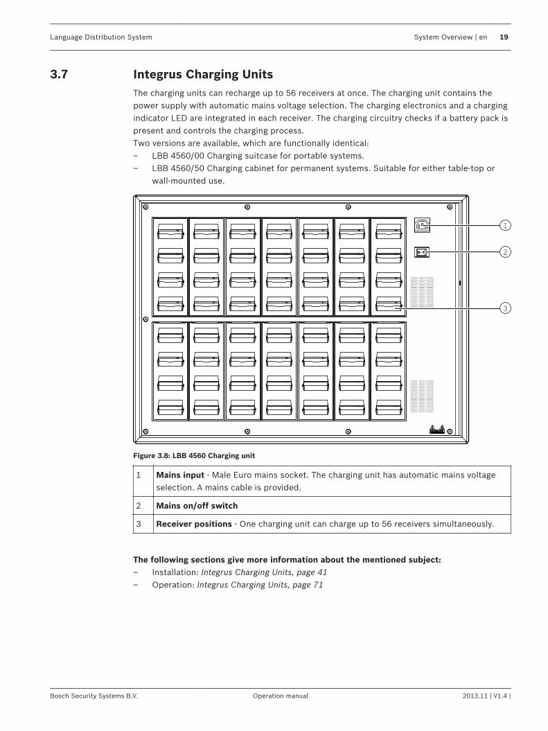
Integrus Charging UnitsThe charging units can recharge up to 56 receivers at once. The charging unit contains thepower supply with automatic mains voltage selection. The charging electronics and a chargingindicator LED are integrated in each receiver. The charging circuitry checks if a battery pack ispresent and controls the charging process.Two versions are available, which are functionally identical:– LBB 4560/00 Charging suitcase for portable systems.– LBB 4560/50 Charging cabinet for permanent systems. Suitable for either table-top or
wall-mounted use.
1
2
3
Figure 3.8: LBB 4560 Charging unit
1 Mains input - Male Euro mains socket. The charging unit has automatic mains voltageselection. A mains cable is provided.
2 Mains on/off switch
3 Receiver positions - One charging unit can charge up to 56 receivers simultaneously.
The following sections give more information about the mentioned subject:– Installation: Integrus Charging Units, page 41– Operation: Integrus Charging Units, page 71
3.7
Language Distribution System System Overview | en 19
Bosch Security Systems B.V. Operation manual 2013.11 | V1.4 |
Planning
System technology
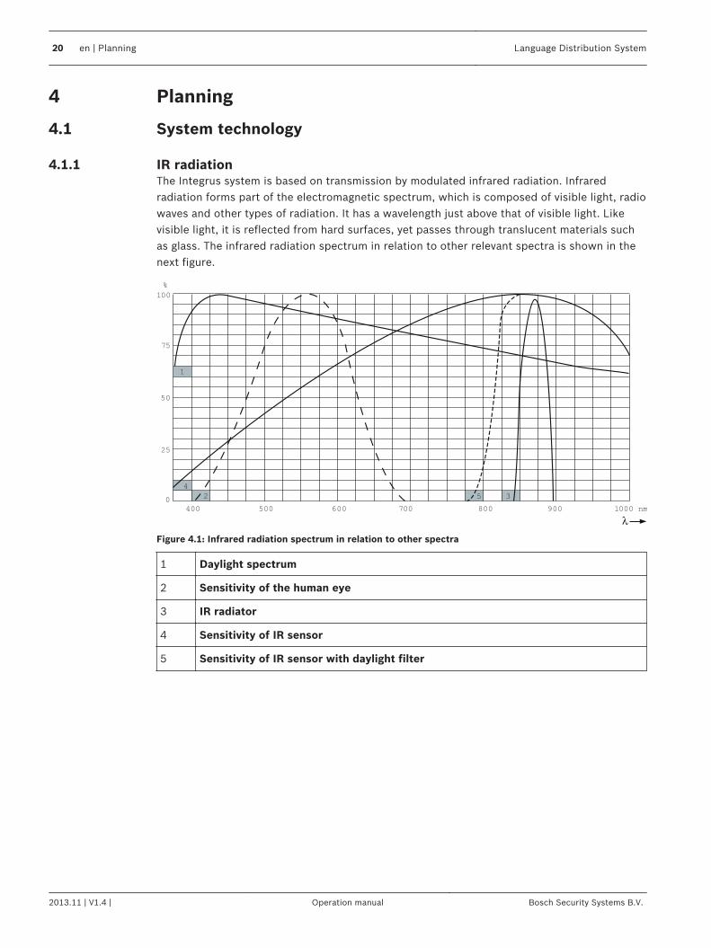
IR radiationThe Integrus system is based on transmission by modulated infrared radiation. Infraredradiation forms part of the electromagnetic spectrum, which is composed of visible light, radiowaves and other types of radiation. It has a wavelength just above that of visible light. Likevisible light, it is reflected from hard surfaces, yet passes through translucent materials suchas glass. The infrared radiation spectrum in relation to other relevant spectra is shown in thenext figure.
100
75
1
4
2
50
25
0
400 500 600 700 800
5 3
900 1000 nm
%
Figure 4.1: Infrared radiation spectrum in relation to other spectra
1 Daylight spectrum
2 Sensitivity of the human eye
3 IR radiator
4 Sensitivity of IR sensor
5 Sensitivity of IR sensor with daylight filter
4
4.1
4.1.1
20 en | Planning Language Distribution System
2013.11 | V1.4 | Operation manual Bosch Security Systems B.V.
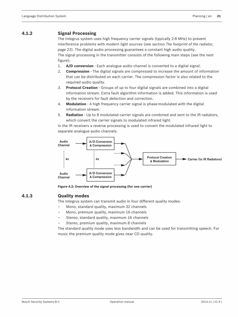
Signal ProcessingThe Integrus system uses high frequency carrier signals (typically 2-8 MHz) to preventinterference problems with modern light sources (see section The footprint of the radiator,page 23). The digital audio processing guarantees a constant high audio quality.The signal processing in the transmitter consists of the following main steps (see the nextfigure):1. A/D conversion - Each analogue audio channel is converted to a digital signal.2. Compression - The digital signals are compressed to increase the amount of information
that can be distributed on each carrier. The compression factor is also related to therequired audio quality.
3. Protocol Creation - Groups of up to four digital signals are combined into a digitalinformation stream. Extra fault algorithm information is added. This information is usedby the receivers for fault detection and correction.
4. Modulation - A high frequency carrier signal is phase-modulated with the digitalinformation stream.
5. Radiation - Up to 8 modulated carrier signals are combined and sent to the IR radiators,which convert the carrier signals to modulated infrared light.
In the IR receivers a reverse processing is used to convert the modulated infrared light toseparate analogue audio channels.
A/D Conversion
& Compression
A/D Conversion
& Compression
Audio
Channel
Audio
Channel
Protocol Creation
& Modulation4x Carrier (to IR Radiators)4x
Figure 4.2: Overview of the signal processing (for one carrier)
Quality modesThe Integrus system can transmit audio in four different quality modes:– Mono, standard quality, maximum 32 channels– Mono, premium quality, maximum 16 channels– Stereo, standard quality, maximum 16 channels– Stereo, premium quality, maximum 8 channelsThe standard quality mode uses less bandwidth and can be used for transmitting speech. Formusic the premium quality mode gives near CD quality.
4.1.2
4.1.3
Language Distribution System Planning | en 21
Bosch Security Systems B.V. Operation manual 2013.11 | V1.4 |
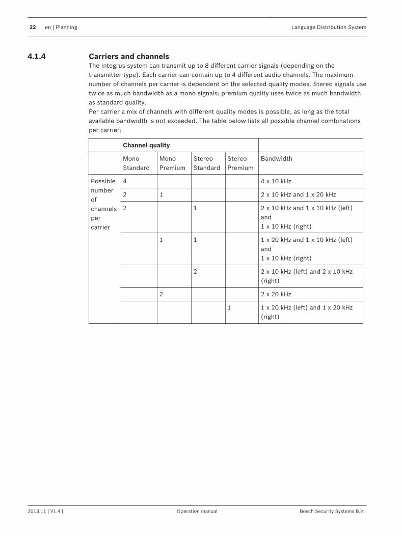
Carriers and channelsThe Integrus system can transmit up to 8 different carrier signals (depending on thetransmitter type). Each carrier can contain up to 4 different audio channels. The maximumnumber of channels per carrier is dependent on the selected quality modes. Stereo signals usetwice as much bandwidth as a mono signals; premium quality uses twice as much bandwidthas standard quality.Per carrier a mix of channels with different quality modes is possible, as long as the totalavailable bandwidth is not exceeded. The table below lists all possible channel combinationsper carrier:
Channel quality
MonoStandard
MonoPremium
StereoStandard
StereoPremium
Bandwidth
Possiblenumberofchannelspercarrier
4 4 x 10 kHz
2 1 2 x 10 kHz and 1 x 20 kHz
2 1 2 x 10 kHz and 1 x 10 kHz (left)and1 x 10 kHz (right)
1 1 1 x 20 kHz and 1 x 10 kHz (left)and1 x 10 kHz (right)
2 2 x 10 kHz (left) and 2 x 10 kHz(right)
2 2 x 20 kHz
1 1 x 20 kHz (left) and 1 x 20 kHz(right)
4.1.4
22 en | Planning Language Distribution System
2013.11 | V1.4 | Operation manual Bosch Security Systems B.V.
Aspects of Infrared distribution systemsA good infrared distribution system ensures that all delegates in a conference venue receivethe distributed signals without disturbance. This is achieved by using enough radiators, placedat well planned positions, so that the conference venue is covered with uniform IR-radiation ofadequate strength. There are several aspects that influence the uniformity and quality of theinfrared signal, which must be considered when planning an infrared radiation distributionsystem. These are discussed in the next sections.
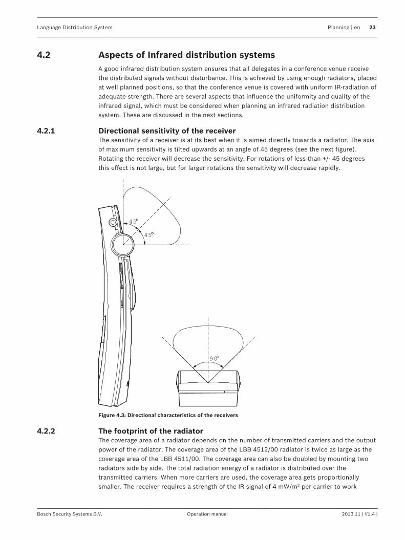
Directional sensitivity of the receiverThe sensitivity of a receiver is at its best when it is aimed directly towards a radiator. The axisof maximum sensitivity is tilted upwards at an angle of 45 degrees (see the next figure).Rotating the receiver will decrease the sensitivity. For rotations of less than +/- 45 degreesthis effect is not large, but for larger rotations the sensitivity will decrease rapidly.
45
45
90
Figure 4.3: Directional characteristics of the receivers
The footprint of the radiatorThe coverage area of a radiator depends on the number of transmitted carriers and the outputpower of the radiator. The coverage area of the LBB 4512/00 radiator is twice as large as thecoverage area of the LBB 4511/00. The coverage area can also be doubled by mounting tworadiators side by side. The total radiation energy of a radiator is distributed over thetransmitted carriers. When more carriers are used, the coverage area gets proportionallysmaller. The receiver requires a strength of the IR signal of 4 mW/m2 per carrier to work
4.2
4.2.1
4.2.2
Language Distribution System Planning | en 23
Bosch Security Systems B.V. Operation manual 2013.11 | V1.4 |
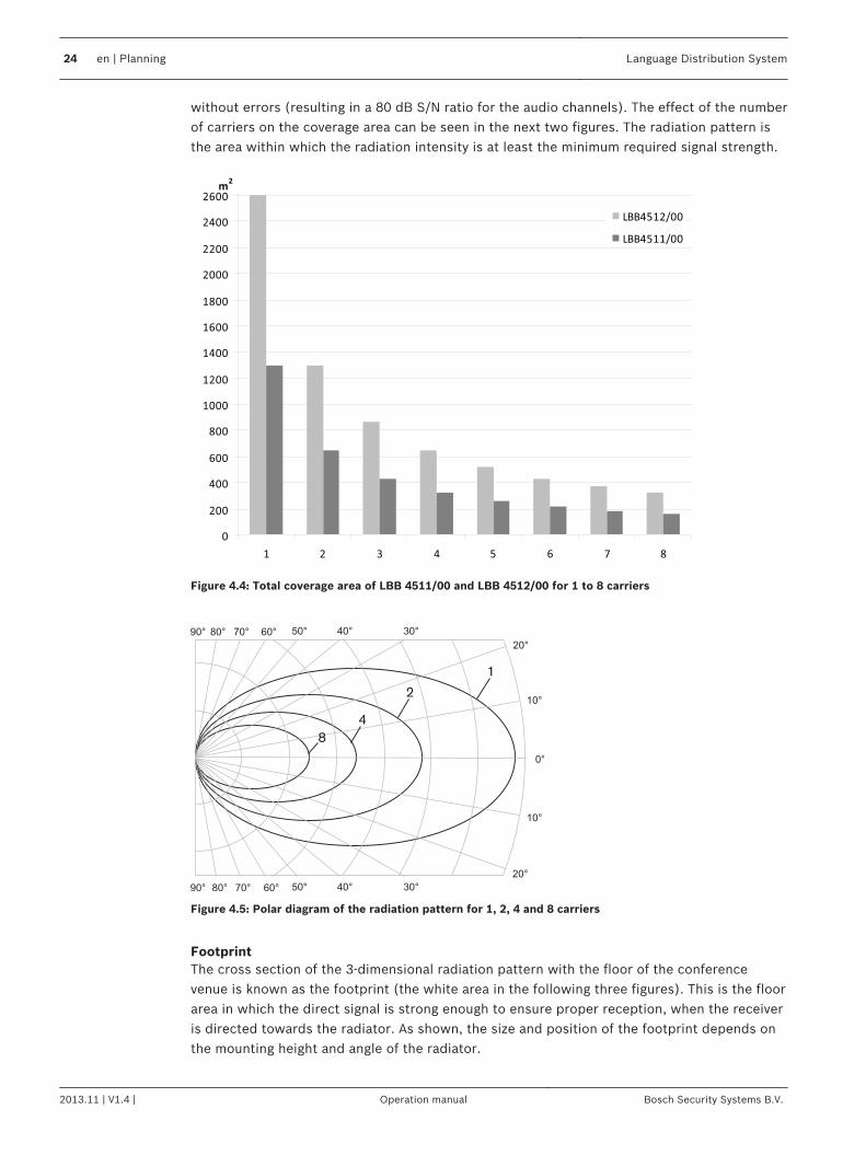
without errors (resulting in a 80 dB S/N ratio for the audio channels). The effect of the numberof carriers on the coverage area can be seen in the next two figures. The radiation pattern isthe area within which the radiation intensity is at least the minimum required signal strength.
0
200
400
600
800
1000
1200
1400
1600
1800
2000
2200
2400
2600
1 2 3 4 5 6 7 8
m2
LBB4512/00
LBB4511/00
Figure 4.4: Total coverage area of LBB 4511/00 and LBB 4512/00 for 1 to 8 carriers
1
8
2
4
Figure 4.5: Polar diagram of the radiation pattern for 1, 2, 4 and 8 carriers
FootprintThe cross section of the 3-dimensional radiation pattern with the floor of the conferencevenue is known as the footprint (the white area in the following three figures). This is the floorarea in which the direct signal is strong enough to ensure proper reception, when the receiveris directed towards the radiator. As shown, the size and position of the footprint depends onthe mounting height and angle of the radiator.
24 en | Planning Language Distribution System
2013.11 | V1.4 | Operation manual Bosch Security Systems B.V.
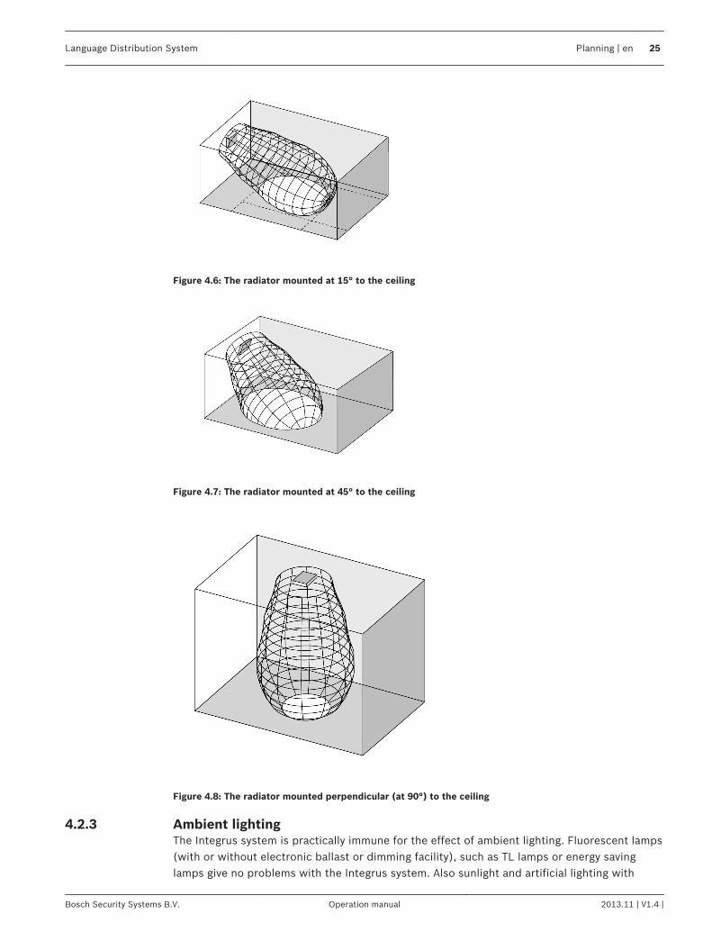
Figure 4.6: The radiator mounted at 15° to the ceiling
Figure 4.7: The radiator mounted at 45° to the ceiling
Figure 4.8: The radiator mounted perpendicular (at 90°) to the ceiling
Ambient lightingThe Integrus system is practically immune for the effect of ambient lighting. Fluorescent lamps(with or without electronic ballast or dimming facility), such as TL lamps or energy savinglamps give no problems with the Integrus system. Also sunlight and artificial lighting with
4.2.3
Language Distribution System Planning | en 25
Bosch Security Systems B.V. Operation manual 2013.11 | V1.4 |
incandescent or halogen lamps up to 1000 lux give no problems with the Integrus system.When high levels of artificial lighting with incandescent or halogen lamps, such as spotlights orstage lighting are applied, you should directly point a radiator at the receivers in order toensure reliable transmission. For venues containing large, unscreened windows, you must planon using additional radiators. For events taking place in the open air a site test will berequired in order to determine the required amount of radiators. With sufficient radiatorsinstalled, the receivers will work without errors, even in bright sunlight.
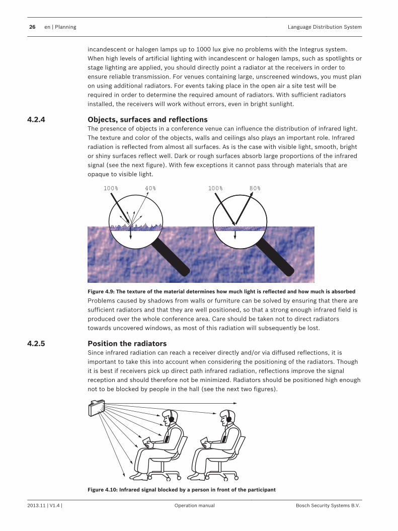
Objects, surfaces and reflectionsThe presence of objects in a conference venue can influence the distribution of infrared light.The texture and color of the objects, walls and ceilings also plays an important role. Infraredradiation is reflected from almost all surfaces. As is the case with visible light, smooth, brightor shiny surfaces reflect well. Dark or rough surfaces absorb large proportions of the infraredsignal (see the next figure). With few exceptions it cannot pass through materials that areopaque to visible light.
100% 40% 100% 80%
Figure 4.9: The texture of the material determines how much light is reflected and how much is absorbed
Problems caused by shadows from walls or furniture can be solved by ensuring that there aresufficient radiators and that they are well positioned, so that a strong enough infrared field isproduced over the whole conference area. Care should be taken not to direct radiatorstowards uncovered windows, as most of this radiation will subsequently be lost.
Position the radiatorsSince infrared radiation can reach a receiver directly and/or via diffused reflections, it isimportant to take this into account when considering the positioning of the radiators. Thoughit is best if receivers pick up direct path infrared radiation, reflections improve the signalreception and should therefore not be minimized. Radiators should be positioned high enoughnot to be blocked by people in the hall (see the next two figures).
Figure 4.10: Infrared signal blocked by a person in front of the participant
4.2.4
4.2.5
26 en | Planning Language Distribution System
2013.11 | V1.4 | Operation manual Bosch Security Systems B.V.
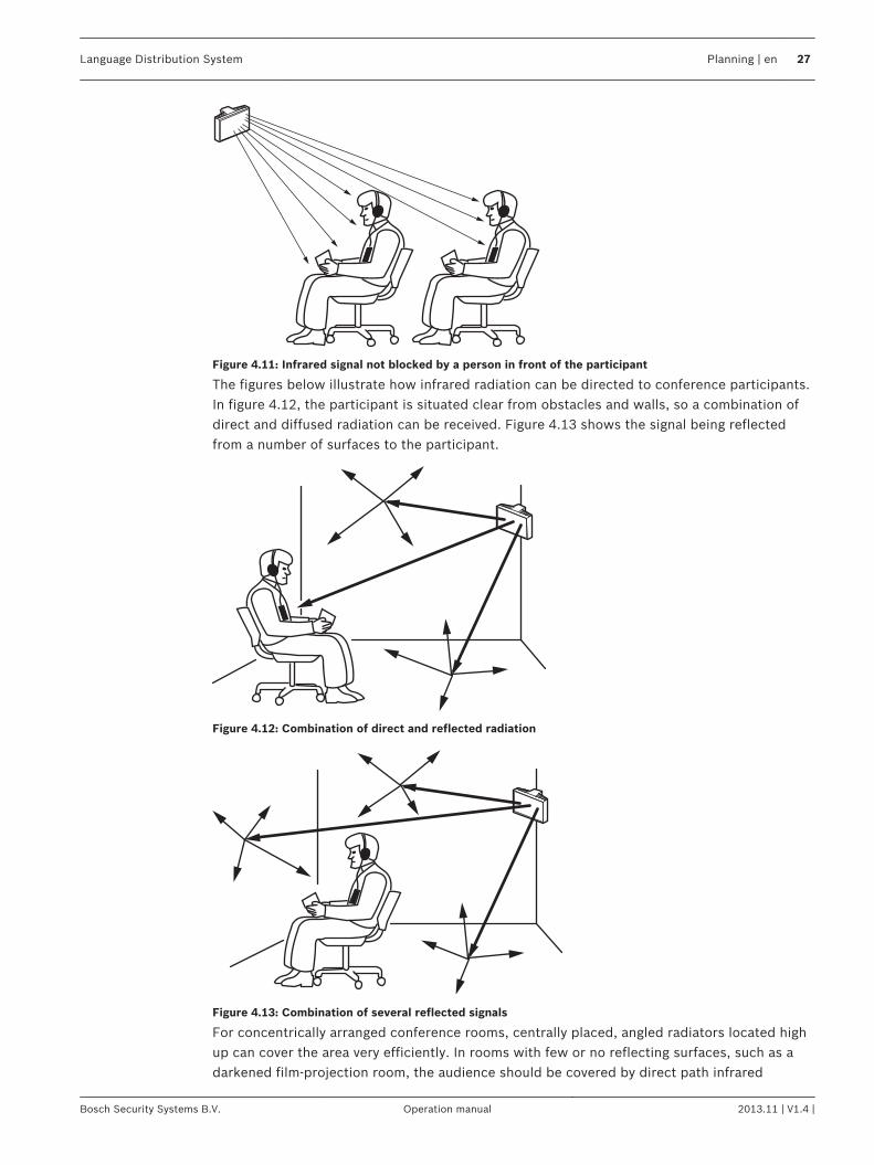
Figure 4.11: Infrared signal not blocked by a person in front of the participant
The figures below illustrate how infrared radiation can be directed to conference participants.In figure 4.12, the participant is situated clear from obstacles and walls, so a combination ofdirect and diffused radiation can be received. Figure 4.13 shows the signal being reflectedfrom a number of surfaces to the participant.
Figure 4.12: Combination of direct and reflected radiation
Figure 4.13: Combination of several reflected signals
For concentrically arranged conference rooms, centrally placed, angled radiators located highup can cover the area very efficiently. In rooms with few or no reflecting surfaces, such as adarkened film-projection room, the audience should be covered by direct path infrared
Language Distribution System Planning | en 27
Bosch Security Systems B.V. Operation manual 2013.11 | V1.4 |
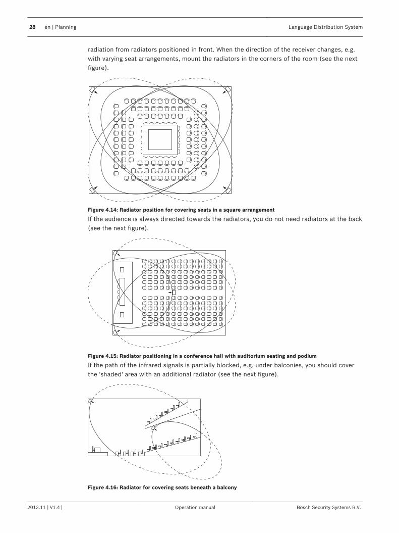
radiation from radiators positioned in front. When the direction of the receiver changes, e.g.with varying seat arrangements, mount the radiators in the corners of the room (see the nextfigure).
Figure 4.14: Radiator position for covering seats in a square arrangement
If the audience is always directed towards the radiators, you do not need radiators at the back(see the next figure).
Figure 4.15: Radiator positioning in a conference hall with auditorium seating and podium
If the path of the infrared signals is partially blocked, e.g. under balconies, you should coverthe 'shaded' area with an additional radiator (see the next figure).
Figure 4.16: Radiator for covering seats beneath a balcony
28 en | Planning Language Distribution System
2013.11 | V1.4 | Operation manual Bosch Security Systems B.V.
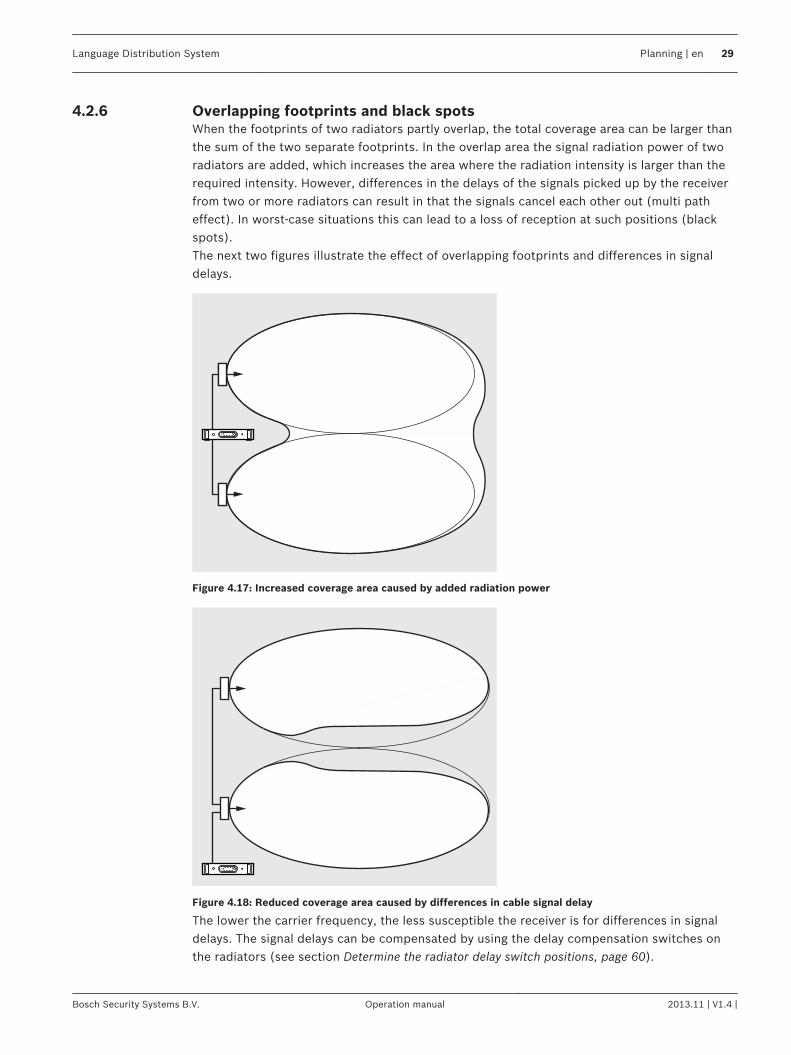
Overlapping footprints and black spotsWhen the footprints of two radiators partly overlap, the total coverage area can be larger thanthe sum of the two separate footprints. In the overlap area the signal radiation power of tworadiators are added, which increases the area where the radiation intensity is larger than therequired intensity. However, differences in the delays of the signals picked up by the receiverfrom two or more radiators can result in that the signals cancel each other out (multi patheffect). In worst-case situations this can lead to a loss of reception at such positions (blackspots).The next two figures illustrate the effect of overlapping footprints and differences in signaldelays.
Figure 4.17: Increased coverage area caused by added radiation power
Figure 4.18: Reduced coverage area caused by differences in cable signal delay
The lower the carrier frequency, the less susceptible the receiver is for differences in signaldelays. The signal delays can be compensated by using the delay compensation switches onthe radiators (see section Determine the radiator delay switch positions, page 60).
4.2.6
Language Distribution System Planning | en 29
Bosch Security Systems B.V. Operation manual 2013.11 | V1.4 |
Plan an Integrus infrared radiation system
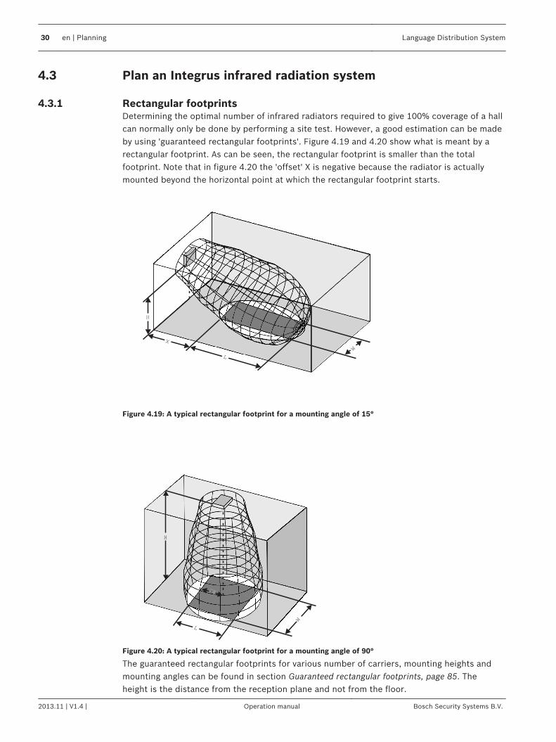
Rectangular footprintsDetermining the optimal number of infrared radiators required to give 100% coverage of a hallcan normally only be done by performing a site test. However, a good estimation can be madeby using 'guaranteed rectangular footprints'. Figure 4.19 and 4.20 show what is meant by arectangular footprint. As can be seen, the rectangular footprint is smaller than the totalfootprint. Note that in figure 4.20 the 'offset' X is negative because the radiator is actuallymounted beyond the horizontal point at which the rectangular footprint starts.
W
H
L
X
Figure 4.19: A typical rectangular footprint for a mounting angle of 15°
X
W
H
L
Figure 4.20: A typical rectangular footprint for a mounting angle of 90°
The guaranteed rectangular footprints for various number of carriers, mounting heights andmounting angles can be found in section Guaranteed rectangular footprints, page 85. Theheight is the distance from the reception plane and not from the floor.
4.3
4.3.1
30 en | Planning Language Distribution System
2013.11 | V1.4 | Operation manual Bosch Security Systems B.V.
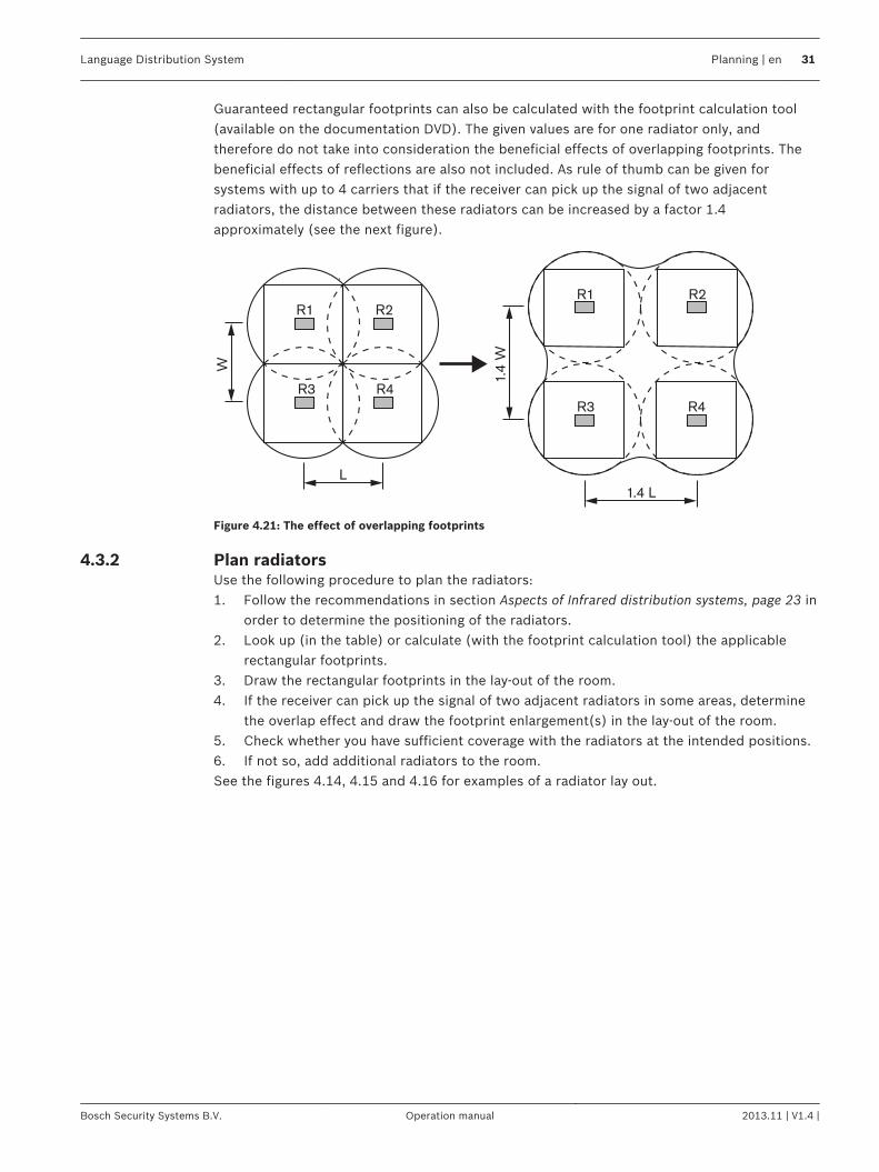
Guaranteed rectangular footprints can also be calculated with the footprint calculation tool(available on the documentation DVD). The given values are for one radiator only, andtherefore do not take into consideration the beneficial effects of overlapping footprints. Thebeneficial effects of reflections are also not included. As rule of thumb can be given forsystems with up to 4 carriers that if the receiver can pick up the signal of two adjacentradiators, the distance between these radiators can be increased by a factor 1.4approximately (see the next figure).
L
R1 R2
R3 R4
R1 R2
R3 R4
W
1.4
W1.4 L
Figure 4.21: The effect of overlapping footprints
Plan radiatorsUse the following procedure to plan the radiators:1. Follow the recommendations in section Aspects of Infrared distribution systems, page 23 in
order to determine the positioning of the radiators.2. Look up (in the table) or calculate (with the footprint calculation tool) the applicable
rectangular footprints.3. Draw the rectangular footprints in the lay-out of the room.4. If the receiver can pick up the signal of two adjacent radiators in some areas, determine
the overlap effect and draw the footprint enlargement(s) in the lay-out of the room.5. Check whether you have sufficient coverage with the radiators at the intended positions.6. If not so, add additional radiators to the room.See the figures 4.14, 4.15 and 4.16 for examples of a radiator lay out.
4.3.2
Language Distribution System Planning | en 31
Bosch Security Systems B.V. Operation manual 2013.11 | V1.4 |
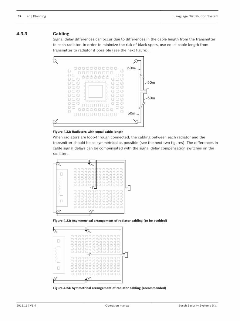
CablingSignal delay differences can occur due to differences in the cable length from the transmitterto each radiator. In order to minimize the risk of black spots, use equal cable length fromtransmitter to radiator if possible (see the next figure).
50m
50m
50m
50m
Figure 4.22: Radiators with equal cable length
When radiators are loop-through connected, the cabling between each radiator and thetransmitter should be as symmetrical as possible (see the next two figures). The differences incable signal delays can be compensated with the signal delay compensation switches on theradiators.
Figure 4.23: Asymmetrical arrangement of radiator cabling (to be avoided)
Figure 4.24: Symmetrical arrangement of radiator cabling (recommended)
4.3.3
32 en | Planning Language Distribution System
2013.11 | V1.4 | Operation manual Bosch Security Systems B.V.
Installation
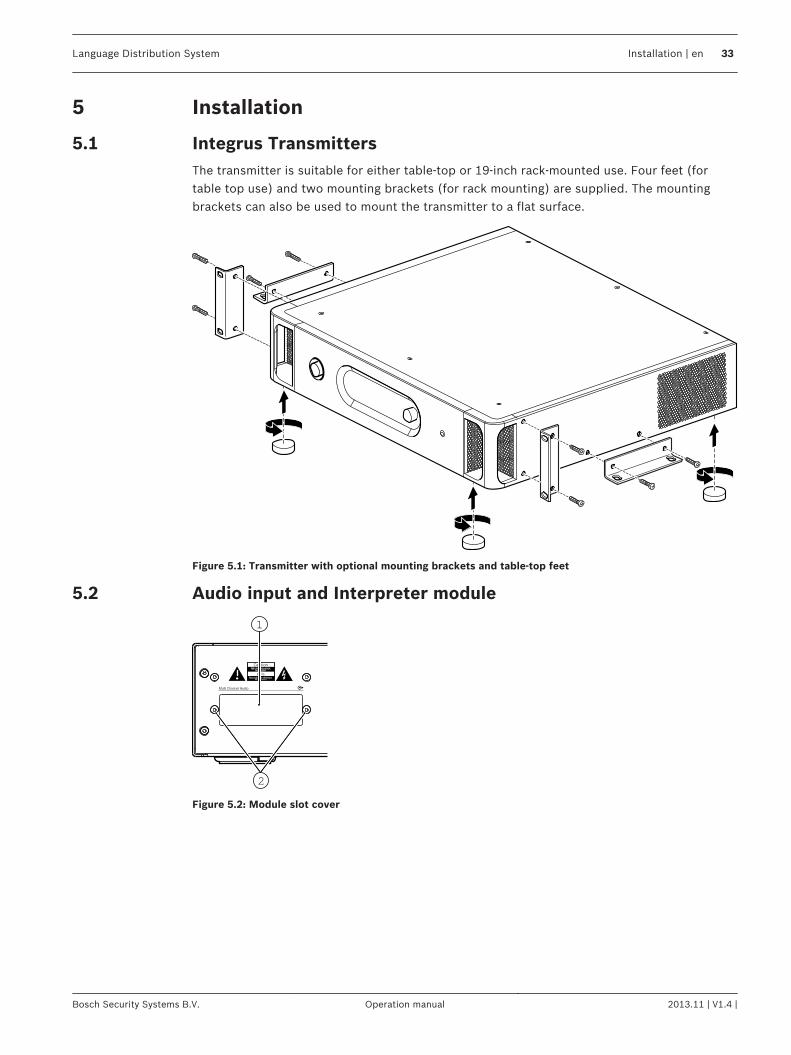
Integrus TransmittersThe transmitter is suitable for either table-top or 19-inch rack-mounted use. Four feet (fortable top use) and two mounting brackets (for rack mounting) are supplied. The mountingbrackets can also be used to mount the transmitter to a flat surface.
Figure 5.1: Transmitter with optional mounting brackets and table-top feet
Audio input and Interpreter module
1
2
Figure 5.2: Module slot cover
5
5.1
5.2
Language Distribution System Installation | en 33
Bosch Security Systems B.V. Operation manual 2013.11 | V1.4 |
3
2
7
5
4
6
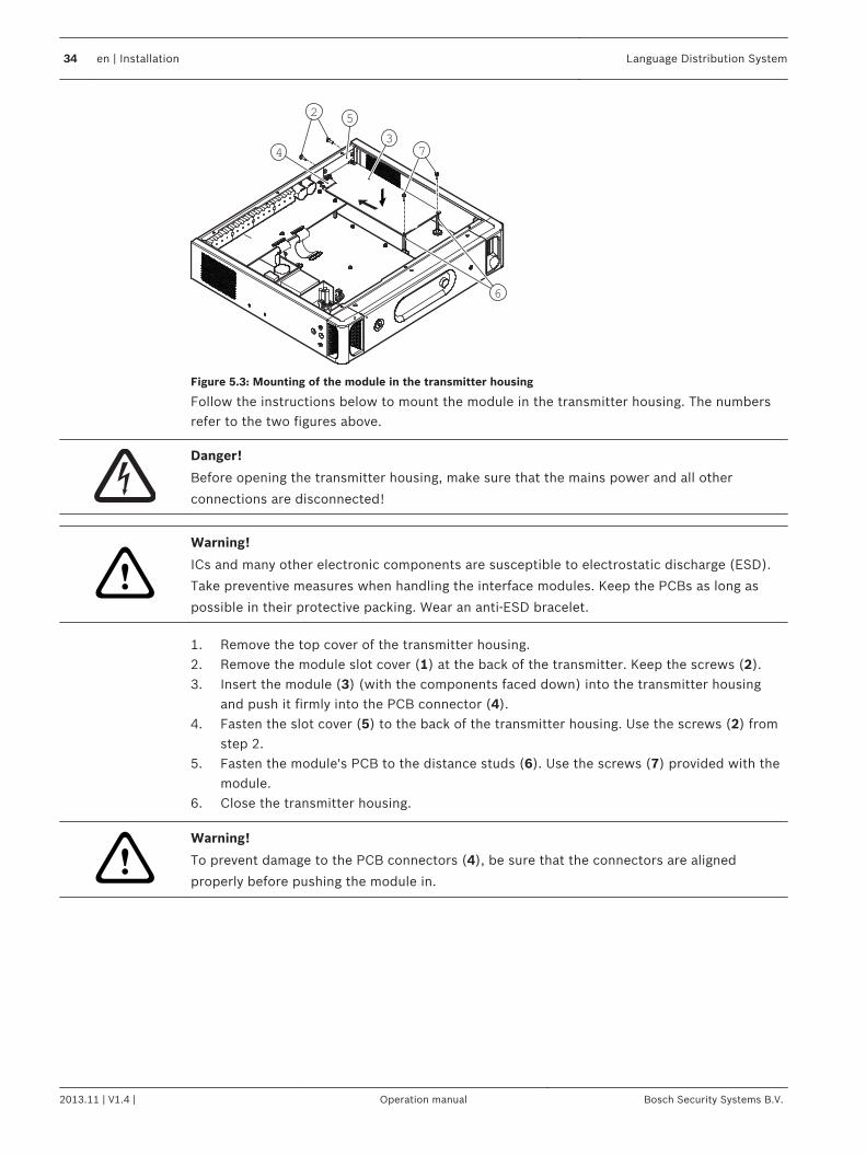
Figure 5.3: Mounting of the module in the transmitter housing
Follow the instructions below to mount the module in the transmitter housing. The numbersrefer to the two figures above.
Danger!
Before opening the transmitter housing, make sure that the mains power and all other
connections are disconnected!
!
Warning!
ICs and many other electronic components are susceptible to electrostatic discharge (ESD).
Take preventive measures when handling the interface modules. Keep the PCBs as long as
possible in their protective packing. Wear an anti-ESD bracelet.
1. Remove the top cover of the transmitter housing.2. Remove the module slot cover (1) at the back of the transmitter. Keep the screws (2).3. Insert the module (3) (with the components faced down) into the transmitter housing
and push it firmly into the PCB connector (4).4. Fasten the slot cover (5) to the back of the transmitter housing. Use the screws (2) from
step 2.5. Fasten the module's PCB to the distance studs (6). Use the screws (7) provided with the
module.6. Close the transmitter housing.
!Warning!
To prevent damage to the PCB connectors (4), be sure that the connectors are aligned
properly before pushing the module in.
34 en | Installation Language Distribution System
2013.11 | V1.4 | Operation manual Bosch Security Systems B.V.
Medium and High Power RadiatorsRadiators in permanent installations can be either fixed to a wall, hung under a ceiling orbalcony or secured to any sturdy material, using the suspension bracket supplied with theradiator. The mounting angle can be adjusted for optimal coverage. For wall mounting aseparate bracket (LBB 3414/00) is also required. In non-permanent installations, a floor standcan be used.
!
Warning!
When you install the radiator in a ceiling, you must leave at least 1 m3 of free space around
the back of the radiator. To prevent the radiator from becoming too hot, make sure that there
is a good airflow in this free space.
Always ensure that natural airflow is not obstructed by ceilings, walls etc. when determining
the position of the radiator. Leave plenty of space around the radiator to prevent it becoming
too hot.
Follow the instructions below to mount a radiator:1. Attach the mounting plate to the suspension bracket, see section Attach mounting plate to
the suspension bracket, page 362. Attach the suspension bracket to the radiator, see section Attach the suspension bracket,
page 373. Do one of the following:
Mount the radiator on a floor stand, see section Mount radiator on a floor stand, page 37Mount the radiator on a wall, see section Mount radiator on a ceiling, page 40Mount the radiator on the ceiling, see section Attach mounting plate to the suspensionbracket, page 36Mount the radiator on top of a horizontal surface, see section Mount radiator on horizontalsurfaces, page 40
4. Secure the radiator with a safety cord, see section Secure the radiator with safety cord.,page 40
5.3
Language Distribution System Installation | en 35
Bosch Security Systems B.V. Operation manual 2013.11 | V1.4 |
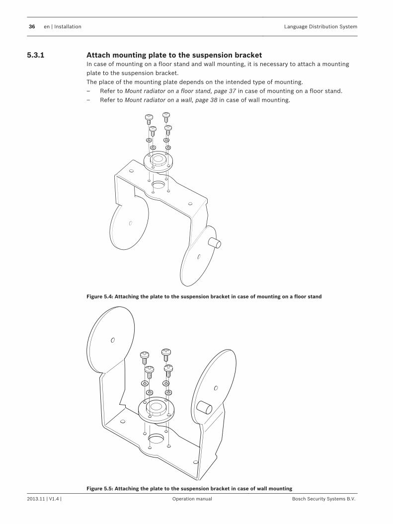
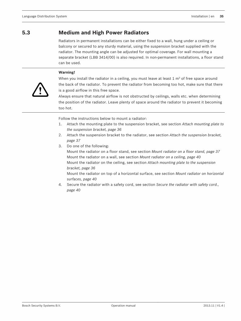
Attach mounting plate to the suspension bracketIn case of mounting on a floor stand and wall mounting, it is necessary to attach a mountingplate to the suspension bracket.The place of the mounting plate depends on the intended type of mounting.– Refer to Mount radiator on a floor stand, page 37 in case of mounting on a floor stand.– Refer to Mount radiator on a wall, page 38 in case of wall mounting.
Figure 5.4: Attaching the plate to the suspension bracket in case of mounting on a floor stand
Figure 5.5: Attaching the plate to the suspension bracket in case of wall mounting
5.3.1
36 en | Installation Language Distribution System
2013.11 | V1.4 | Operation manual Bosch Security Systems B.V.
Attach the suspension bracket
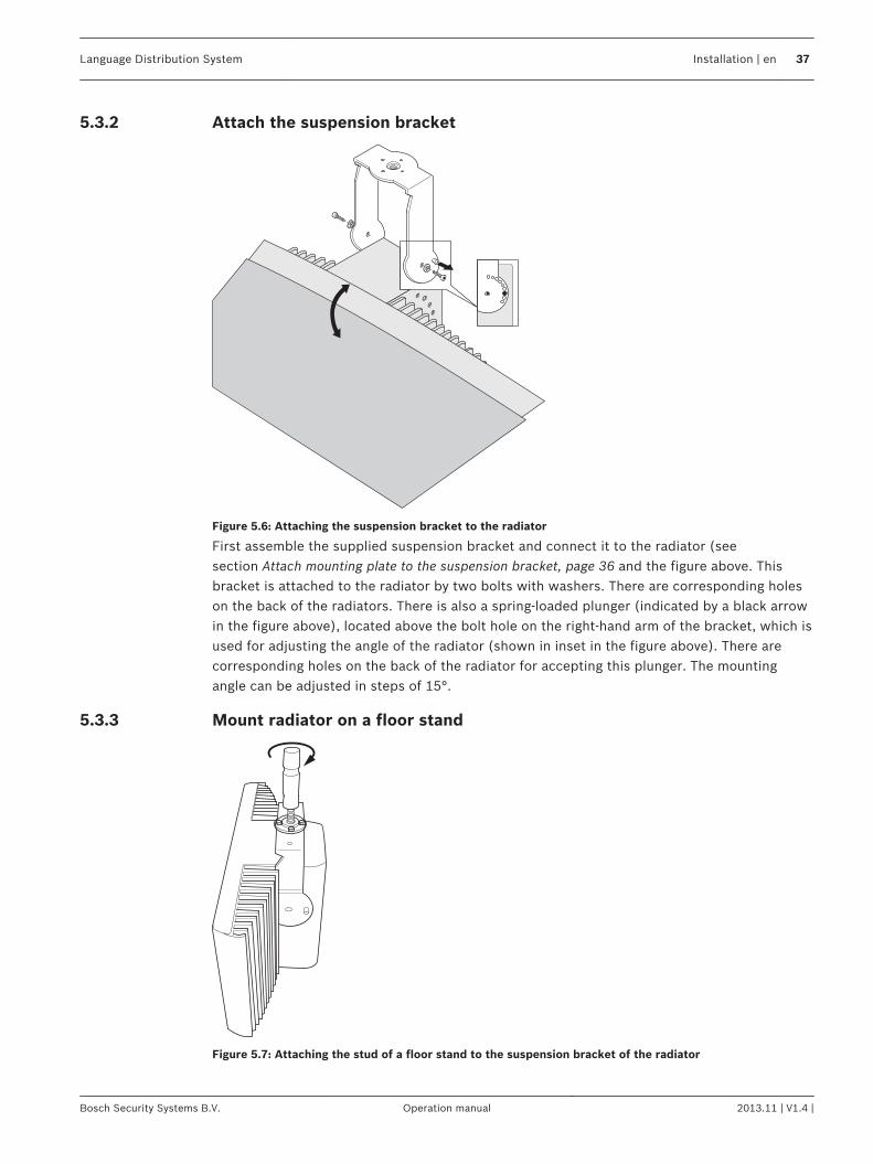
Figure 5.6: Attaching the suspension bracket to the radiator
First assemble the supplied suspension bracket and connect it to the radiator (seesection Attach mounting plate to the suspension bracket, page 36 and the figure above. Thisbracket is attached to the radiator by two bolts with washers. There are corresponding holeson the back of the radiators. There is also a spring-loaded plunger (indicated by a black arrowin the figure above), located above the bolt hole on the right-hand arm of the bracket, which isused for adjusting the angle of the radiator (shown in inset in the figure above). There arecorresponding holes on the back of the radiator for accepting this plunger. The mountingangle can be adjusted in steps of 15°.
Mount radiator on a floor stand
Figure 5.7: Attaching the stud of a floor stand to the suspension bracket of the radiator
5.3.2
5.3.3
Language Distribution System Installation | en 37
Bosch Security Systems B.V. Operation manual 2013.11 | V1.4 |
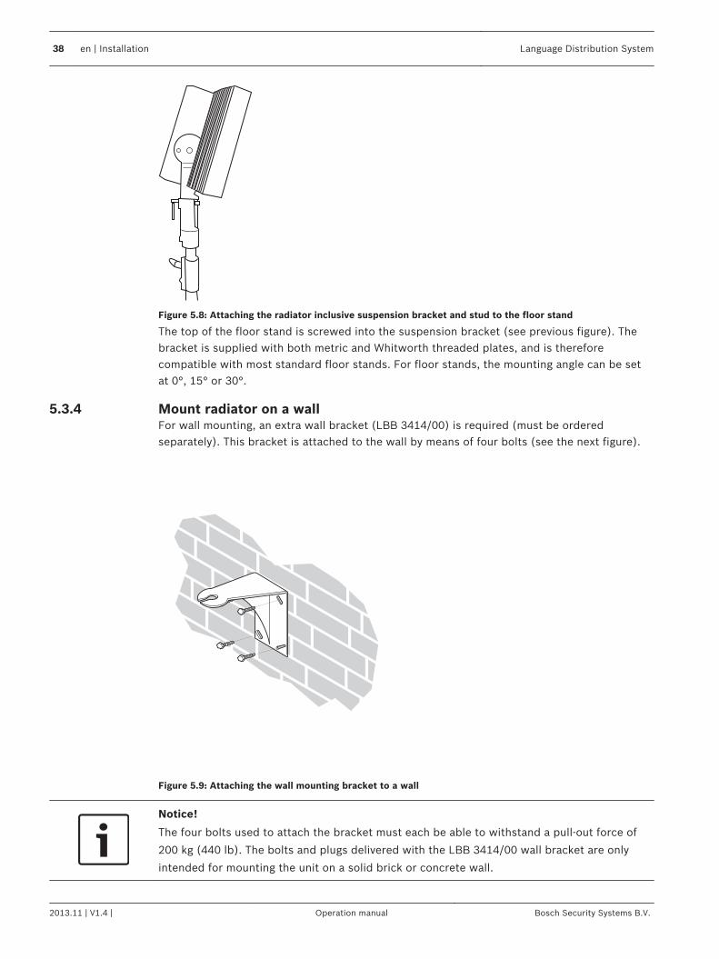
Figure 5.8: Attaching the radiator inclusive suspension bracket and stud to the floor stand
The top of the floor stand is screwed into the suspension bracket (see previous figure). Thebracket is supplied with both metric and Whitworth threaded plates, and is thereforecompatible with most standard floor stands. For floor stands, the mounting angle can be setat 0°, 15° or 30°.
Mount radiator on a wallFor wall mounting, an extra wall bracket (LBB 3414/00) is required (must be orderedseparately). This bracket is attached to the wall by means of four bolts (see the next figure).
Figure 5.9: Attaching the wall mounting bracket to a wall
Notice!
The four bolts used to attach the bracket must each be able to withstand a pull-out force of
200 kg (440 lb). The bolts and plugs delivered with the LBB 3414/00 wall bracket are only
intended for mounting the unit on a solid brick or concrete wall.
5.3.4
38 en | Installation Language Distribution System
2013.11 | V1.4 | Operation manual Bosch Security Systems B.V.
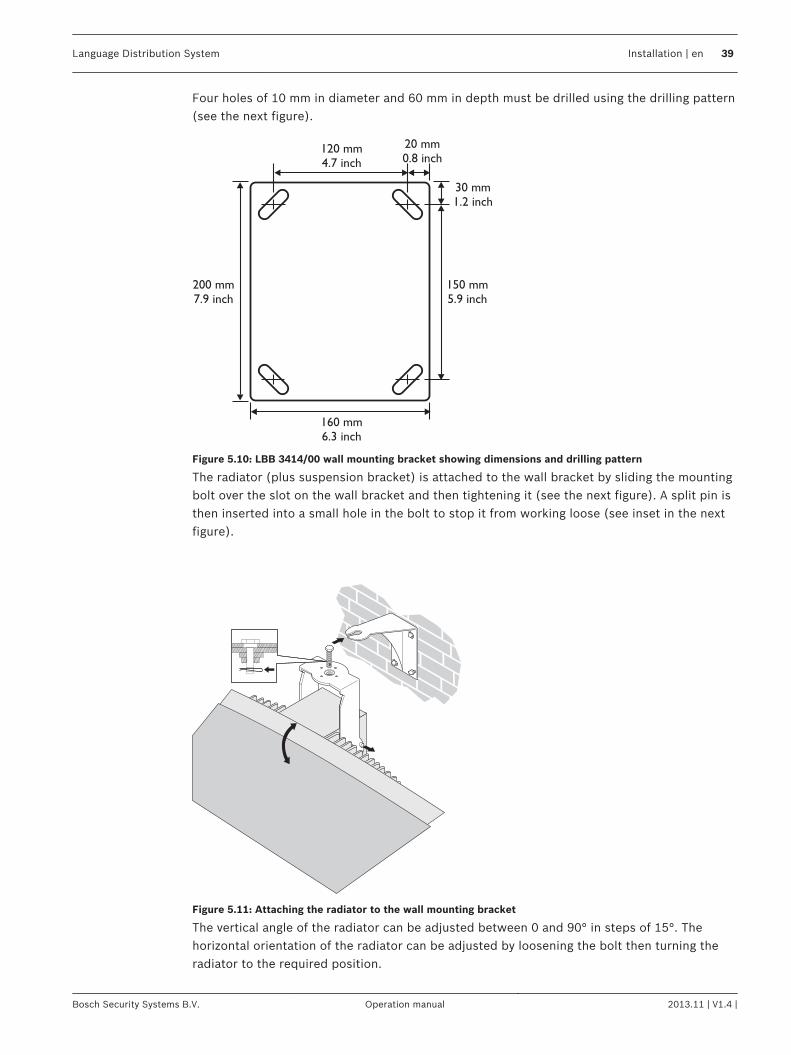
Four holes of 10 mm in diameter and 60 mm in depth must be drilled using the drilling pattern(see the next figure).
Figure 5.10: LBB 3414/00 wall mounting bracket showing dimensions and drilling pattern
The radiator (plus suspension bracket) is attached to the wall bracket by sliding the mountingbolt over the slot on the wall bracket and then tightening it (see the next figure). A split pin isthen inserted into a small hole in the bolt to stop it from working loose (see inset in the nextfigure).
Figure 5.11: Attaching the radiator to the wall mounting bracket
The vertical angle of the radiator can be adjusted between 0 and 90° in steps of 15°. Thehorizontal orientation of the radiator can be adjusted by loosening the bolt then turning theradiator to the required position.
Language Distribution System Installation | en 39
Bosch Security Systems B.V. Operation manual 2013.11 | V1.4 |
Mount radiator on a ceilingThe radiators can be attached to the ceiling using the supplied suspension bracket. Thisensures enough space for a proper air flow around the radiator. Mounting a radiator in theceiling will in most cases require a forced air flow by means of a ventilator to preventoverheating. If this is not possible, switch the radiator to half power.
Mount radiator on horizontal surfacesWhen the radiator has to be positioned a horizontal surface (e.g. on top of an interpreterbooth), the distance between the radiator and the surface must be at least 4 cm (1.5 inch) toenable enough air flow around the radiator. This can be achieved by using the suspensionbracket as a support. If this is not possible, switch the radiator to half power. If the radiator isused at full power on top of an interpreter booth, the ambient temperature must not exceed35° C.
Secure the radiator with safety cord.The radiator is supplied with a safety eye to secure the radiator with a safety cord (notsupplied).1. Mount the safety eye properly in the hole of the radiator.2. Make sure that: The minimum strength of the safety cord, mounting material, shackle and
supporting building structure should withstand 1,500 N. The length of the safety cord isnot more than 20 cm longer than needed.
3. Mount the safety cord to the safety eye.4. Mount the safety cord to the supporting building structure.
!
Warning!
Suspending any object is potentially dangerous and should only be attempted by individuals
who have a thorough knowledge of the techniques and regulations of rigging objects
overhead. Bosch strongly recommends that radiators be suspended taking into account all
current national, federal, state and local regulations.
It is the responsibility of the installer to ensure that radiators are safely installed in
accordance with all such regulations. If radiators are suspended, Bosch strongly recommends
that the installation is inspected at least once a year. If any sign of weakness or damage is
detected, remedial action should be taken immediately.
Integrus receiversThe infrared receivers can operate with disposable batteries (2x AA-size alkaline cells) or witha rechargeable battery pack (LBB 4550/10).Insert the batteries or the battery pack in the receiver with the correct polarity as indicated inthe battery compartment. The battery pack has a separate connection cable which must beconnected to the receiver. When this connection is not present, the charging circuitry in thereceiver will not work. This also prevents the unwanted charging of disposable batteries. Thebattery pack has a temperature sensor which prevents overheating during charging.For more information about charging the battery pack see section Integrus Charging Units,page 71.
Notice!
Disposable batteries and battery packs at the end of their technical lives should be discarded
with due care for the environment. When possible, take batteries to a local recycling station.
5.3.5
5.3.6
5.3.7
5.4
40 en | Installation Language Distribution System
2013.11 | V1.4 | Operation manual Bosch Security Systems B.V.
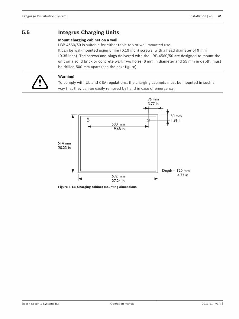
Integrus Charging UnitsMount charging cabinet on a wallLBB 4560/50 is suitable for either table-top or wall-mounted use.It can be wall-mounted using 5 mm (0.19 inch) screws, with a head diameter of 9 mm(0.35 inch). The screws and plugs delivered with the LBB 4560/50 are designed to mount theunit on a solid brick or concrete wall. Two holes, 8 mm in diameter and 55 mm in depth, mustbe drilled 500 mm apart (see the next figure).
!Warning!
To comply with UL and CSA regulations, the charging cabinets must be mounted in such a
way that they can be easily removed by hand in case of emergency.
Figure 5.12: Charging cabinet mounting dimensions
5.5
Language Distribution System Installation | en 41
Bosch Security Systems B.V. Operation manual 2013.11 | V1.4 |
Connection
Integrus TransmittersThis section gives an overview of typical system connections using the INT‑TX rangetransmitter:– The DCN Next Generation system– Other external audio sources– An emergency signal switch– Another transmitter– Radiators
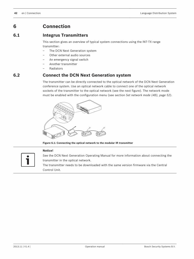
Connect the DCN Next Generation systemThe transmitter can be directly connected to the optical network of the DCN Next Generationconference system. Use an optical network cable to connect one of the optical networksockets of the transmitter to the optical network (see the next figure). The network modemust be enabled with the configuration menu (see section Set network mode (4B), page 52).
5
6
1
2
Network
1
2
3
4
5
6
1
2
Network
Figure 6.1: Connecting the optical network to the modular IR transmitter
Notice!
See the DCN Next Generation Operating Manual for more information about connecting the
transmitter in the optical network.
The transmitter needs to be downloaded with the same version firmware via the Central
Control Unit.
6
6.1
6.2
42 en | Connection Language Distribution System
2013.11 | V1.4 | Operation manual Bosch Security Systems B.V.
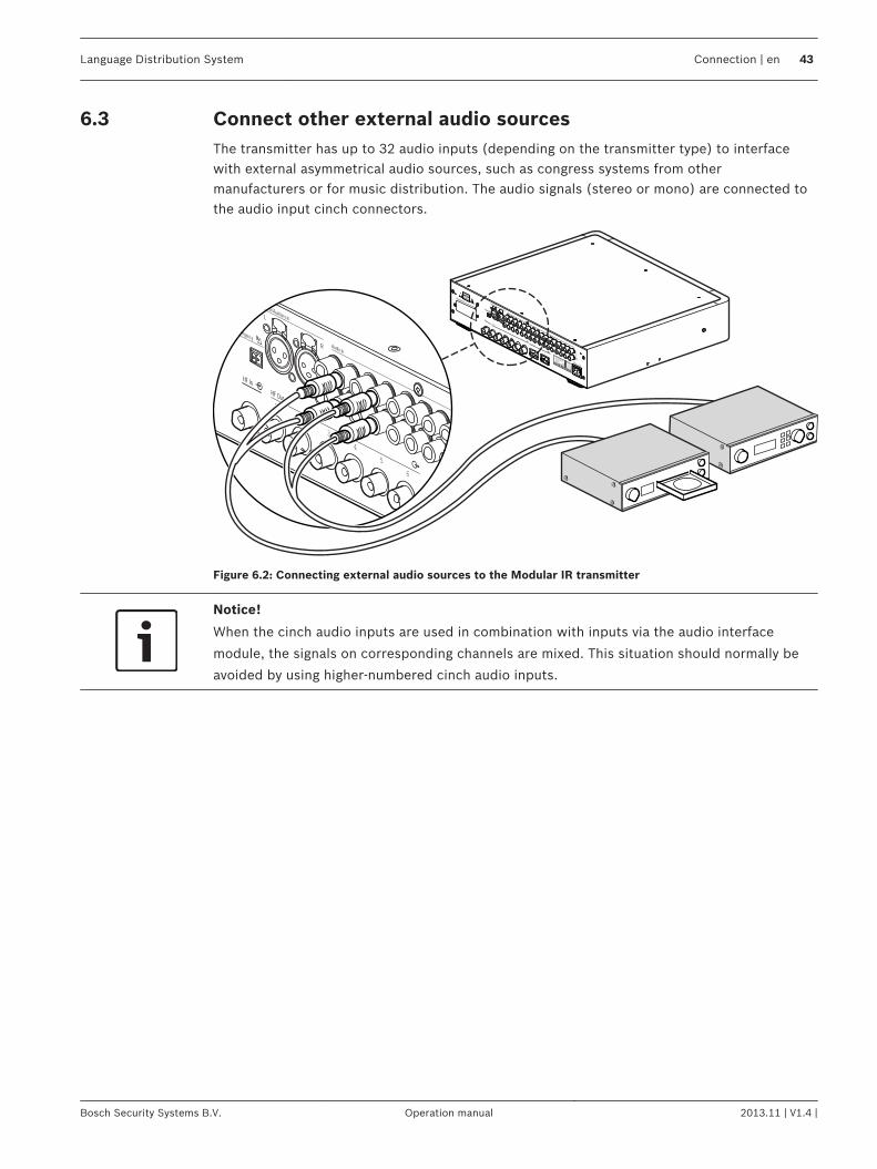
Connect other external audio sourcesThe transmitter has up to 32 audio inputs (depending on the transmitter type) to interfacewith external asymmetrical audio sources, such as congress systems from othermanufacturers or for music distribution. The audio signals (stereo or mono) are connected tothe audio input cinch connectors.
1
2
3
4
5
6
1
2
3
4
5
6
1
2
Network
Figure 6.2: Connecting external audio sources to the Modular IR transmitter
Notice!
When the cinch audio inputs are used in combination with inputs via the audio interface
module, the signals on corresponding channels are mixed. This situation should normally be
avoided by using higher‑numbered cinch audio inputs.
6.3
Language Distribution System Connection | en 43
Bosch Security Systems B.V. Operation manual 2013.11 | V1.4 |
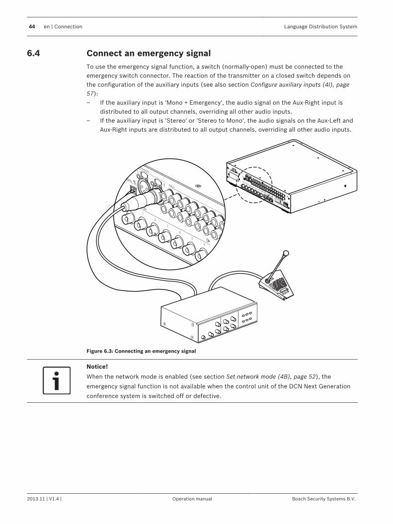
Connect an emergency signalTo use the emergency signal function, a switch (normally-open) must be connected to theemergency switch connector. The reaction of the transmitter on a closed switch depends onthe configuration of the auxiliary inputs (see also section Configure auxiliary inputs (4I), page57):– If the auxiliary input is 'Mono + Emergency', the audio signal on the Aux‑Right input is
distributed to all output channels, overriding all other audio inputs.– If the auxiliary input is 'Stereo' or 'Stereo to Mono', the audio signals on the Aux‑Left and
Aux‑Right inputs are distributed to all output channels, overriding all other audio inputs.
1
2
3
4
5
6
1
2
3
4
5
6
1
2
Network
Figure 6.3: Connecting an emergency signal
Notice!
When the network mode is enabled (see section Set network mode (4B), page 52), the
emergency signal function is not available when the control unit of the DCN Next Generation
conference system is switched off or defective.
6.4
44 en | Connection Language Distribution System
2013.11 | V1.4 | Operation manual Bosch Security Systems B.V.
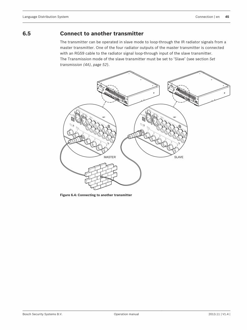
Connect to another transmitterThe transmitter can be operated in slave mode to loop-through the IR radiator signals from amaster transmitter. One of the four radiator outputs of the master transmitter is connectedwith an RG59 cable to the radiator signal loop-through input of the slave transmitter.The Transmission mode of the slave transmitter must be set to ‘Slave’ (see section Settransmission (4A), page 52).
1
2
3
4
5
6
1
2
3
4
5
6
MASTER SLAVE
1
2
3
4
5
6
1
2
Network
1
2
3
4
5
6
1
2
Network
Figure 6.4: Connecting to another transmitter
6.5
Language Distribution System Connection | en 45
Bosch Security Systems B.V. Operation manual 2013.11 | V1.4 |
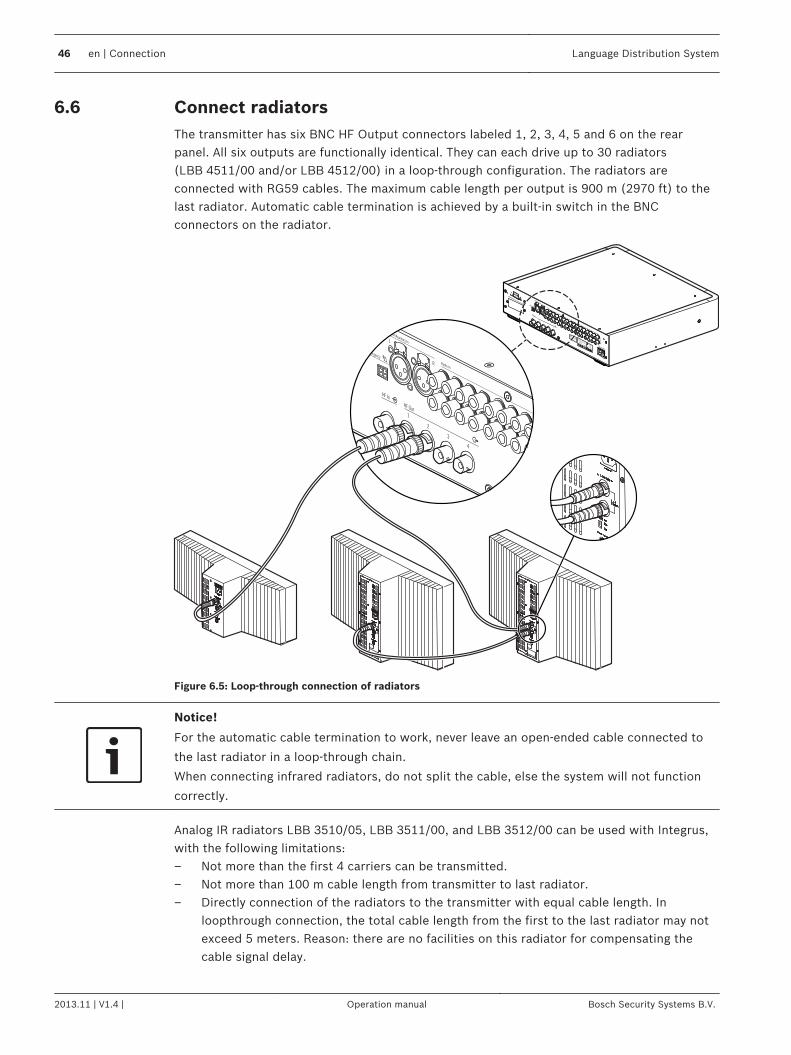
Connect radiatorsThe transmitter has six BNC HF Output connectors labeled 1, 2, 3, 4, 5 and 6 on the rearpanel. All six outputs are functionally identical. They can each drive up to 30 radiators(LBB 4511/00 and/or LBB 4512/00) in a loop‑through configuration. The radiators areconnected with RG59 cables. The maximum cable length per output is 900 m (2970 ft) to thelast radiator. Automatic cable termination is achieved by a built-in switch in the BNCconnectors on the radiator.
Figure 6.5: Loop-through connection of radiators
Notice!
For the automatic cable termination to work, never leave an open-ended cable connected to
the last radiator in a loop-through chain.
When connecting infrared radiators, do not split the cable, else the system will not function
correctly.
Analog IR radiators LBB 3510/05, LBB 3511/00, and LBB 3512/00 can be used with Integrus,with the following limitations:– Not more than the first 4 carriers can be transmitted.– Not more than 100 m cable length from transmitter to last radiator.– Directly connection of the radiators to the transmitter with equal cable length. In
loopthrough connection, the total cable length from the first to the last radiator may notexceed 5 meters. Reason: there are no facilities on this radiator for compensating thecable signal delay.
6.6
46 en | Connection Language Distribution System
2013.11 | V1.4 | Operation manual Bosch Security Systems B.V.

– Don't use this radiator in combination with LBB 4511/00 and LBB 4512/00 radiators inone system, as the internal signal delay of these radiators are different.
– No automatic cable termination: the termination plug has to be connected to the lastradiator in a trunk.
– No communication of the radiator status to the transmitter.
Language Distribution System Connection | en 47
Bosch Security Systems B.V. Operation manual 2013.11 | V1.4 |
Configuration
Integrus transmitter
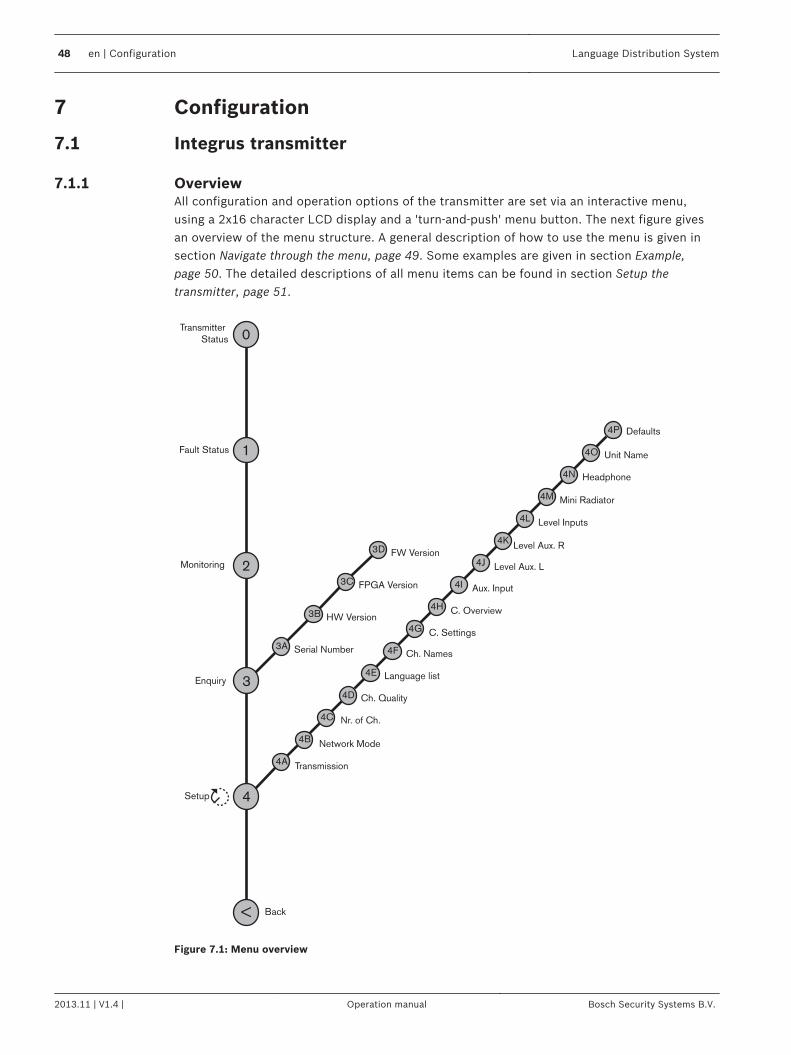
OverviewAll configuration and operation options of the transmitter are set via an interactive menu,using a 2x16 character LCD display and a 'turn-and-push' menu button. The next figure givesan overview of the menu structure. A general description of how to use the menu is given insection Navigate through the menu, page 49. Some examples are given in section Example,page 50. The detailed descriptions of all menu items can be found in section Setup thetransmitter, page 51.
4
4A Transmission
Nr. of Ch.
3
3A
Ch. Quality
Network Mode
2
1
0Transmitter
Status
Fault Status
Monitoring
Enquiry
< Back
Setup
Serial Number Ch. Names
C. Settings
C. Overview
Aux. Input
Level Aux. L
Level Aux. R
Level Inputs
Unit Name
Mini Radiator
Headphone
Defaults
3B HW Version
3C FPGA Version
3D FW Version
4C
4B
4D
4E
4F
4G
4H
4I
4J
4K
4L
4M
4N
4O
4P
Language list
Figure 7.1: Menu overview
7
7.1
7.1.1
48 en | Configuration Language Distribution System
2013.11 | V1.4 | Operation manual Bosch Security Systems B.V.
Navigate through the menu
4D Ch. QualityPer Channel ...
main menuitem number
sub-menuitem character
three dots indicatethat the item has asub-menu
menu item title4D Channel 12Stereo PQ In 03
option values
Figure 7.2: Menu item screen elements
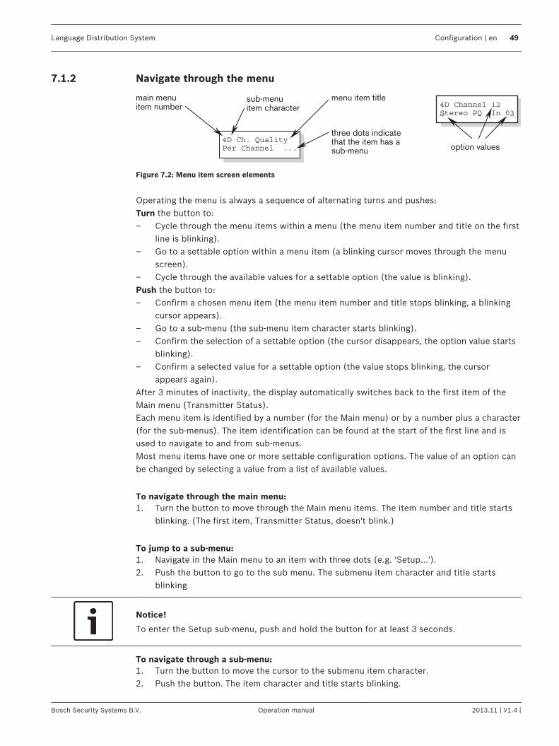
Operating the menu is always a sequence of alternating turns and pushes:Turn the button to:– Cycle through the menu items within a menu (the menu item number and title on the first
line is blinking).– Go to a settable option within a menu item (a blinking cursor moves through the menu
screen).– Cycle through the available values for a settable option (the value is blinking).Push the button to:– Confirm a chosen menu item (the menu item number and title stops blinking, a blinking
cursor appears).– Go to a sub-menu (the sub-menu item character starts blinking).– Confirm the selection of a settable option (the cursor disappears, the option value starts
blinking).– Confirm a selected value for a settable option (the value stops blinking, the cursor
appears again).After 3 minutes of inactivity, the display automatically switches back to the first item of theMain menu (Transmitter Status).Each menu item is identified by a number (for the Main menu) or by a number plus a character(for the sub-menus). The item identification can be found at the start of the first line and isused to navigate to and from sub-menus.Most menu items have one or more settable configuration options. The value of an option canbe changed by selecting a value from a list of available values.
To navigate through the main menu:1. Turn the button to move through the Main menu items. The item number and title starts
blinking. (The first item, Transmitter Status, doesn't blink.)
To jump to a sub-menu:1. Navigate in the Main menu to an item with three dots (e.g. 'Setup...').2. Push the button to go to the sub menu. The submenu item character and title starts
blinking
Notice!
To enter the Setup sub-menu, push and hold the button for at least 3 seconds.
To navigate through a sub-menu:1. Turn the button to move the cursor to the submenu item character.2. Push the button. The item character and title starts blinking.
7.1.2
Language Distribution System Configuration | en 49
Bosch Security Systems B.V. Operation manual 2013.11 | V1.4 |
3. Turn to select another sub-menu item character.4. Push to confirm the selection.
To change the option values:1. Navigate to the applicable menu item.2. Turn the button to move the cursor to the option value you want to change.3. Push the button to activate the option. The option value starts to blink.4. Turn the button to select a new option value.5. Push the button to confirm the new value. The option value stops blinking.6. Turn the button to move the cursor to another settable option (when available) and
repeat steps 3 to 5.
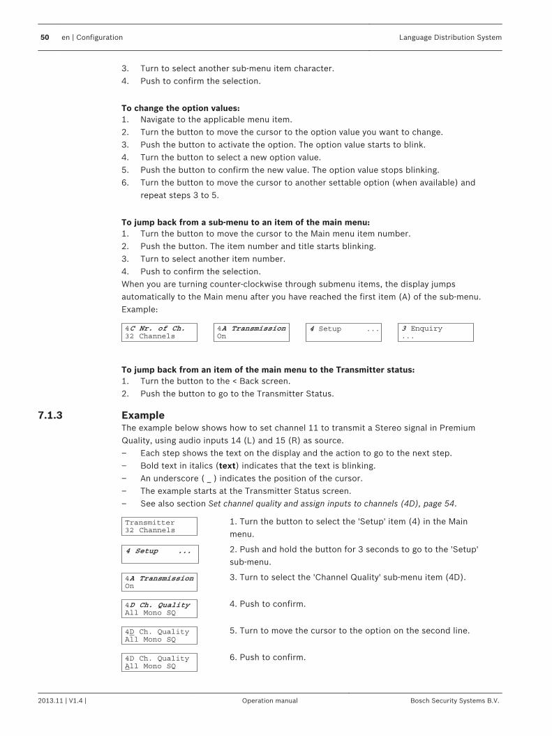
To jump back from a sub-menu to an item of the main menu:1. Turn the button to move the cursor to the Main menu item number.2. Push the button. The item number and title starts blinking.3. Turn to select another item number.4. Push to confirm the selection.When you are turning counter-clockwise through submenu items, the display jumpsautomatically to the Main menu after you have reached the first item (A) of the sub-menu.Example:
To jump back from an item of the main menu to the Transmitter status:1. Turn the button to the < Back screen.2. Push the button to go to the Transmitter Status.
ExampleThe example below shows how to set channel 11 to transmit a Stereo signal in PremiumQuality, using audio inputs 14 (L) and 15 (R) as source.– Each step shows the text on the display and the action to go to the next step.– Bold text in italics (text) indicates that the text is blinking.– An underscore ( _ ) indicates the position of the cursor.– The example starts at the Transmitter Status screen.– See also section Set channel quality and assign inputs to channels (4D), page 54.
1. Turn the button to select the 'Setup' item (4) in the Mainmenu.
2. Push and hold the button for 3 seconds to go to the 'Setup'sub-menu.
3. Turn to select the 'Channel Quality' sub-menu item (4D).
4. Push to confirm.
5. Turn to move the cursor to the option on the second line.
6. Push to confirm.
7.1.3
50 en | Configuration Language Distribution System
2013.11 | V1.4 | Operation manual Bosch Security Systems B.V.
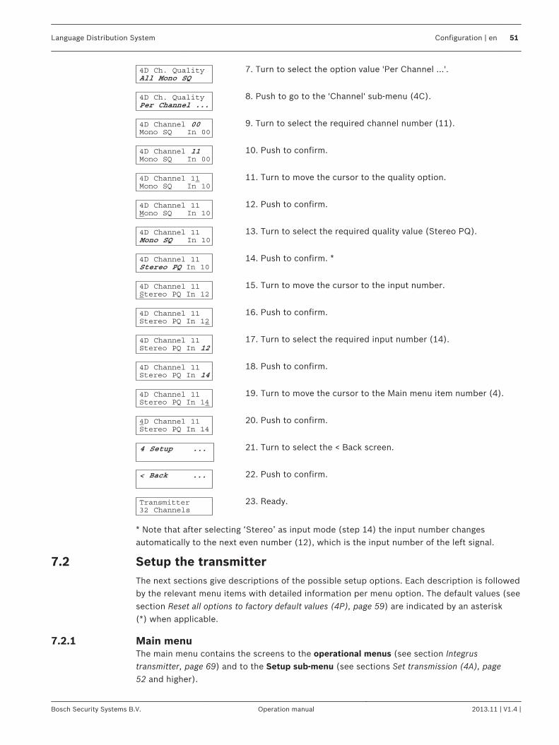
7. Turn to select the option value 'Per Channel ...'.
8. Push to go to the 'Channel' sub-menu (4C).
9. Turn to select the required channel number (11).
10. Push to confirm.
11. Turn to move the cursor to the quality option.
12. Push to confirm.
13. Turn to select the required quality value (Stereo PQ).
14. Push to confirm. *
15. Turn to move the cursor to the input number.
16. Push to confirm.
17. Turn to select the required input number (14).
18. Push to confirm.
19. Turn to move the cursor to the Main menu item number (4).
20. Push to confirm.
21. Turn to select the < Back screen.
22. Push to confirm.
23. Ready.
* Note that after selecting ‘Stereo’ as input mode (step 14) the input number changesautomatically to the next even number (12), which is the input number of the left signal.
Setup the transmitterThe next sections give descriptions of the possible setup options. Each description is followedby the relevant menu items with detailed information per menu option. The default values (seesection Reset all options to factory default values (4P), page 59) are indicated by an asterisk(*) when applicable.
Main menuThe main menu contains the screens to the operational menus (see section Integrustransmitter, page 69) and to the Setup sub-menu (see sections Set transmission (4A), page52 and higher).
7.2
7.2.1
Language Distribution System Configuration | en 51
Bosch Security Systems B.V. Operation manual 2013.11 | V1.4 |
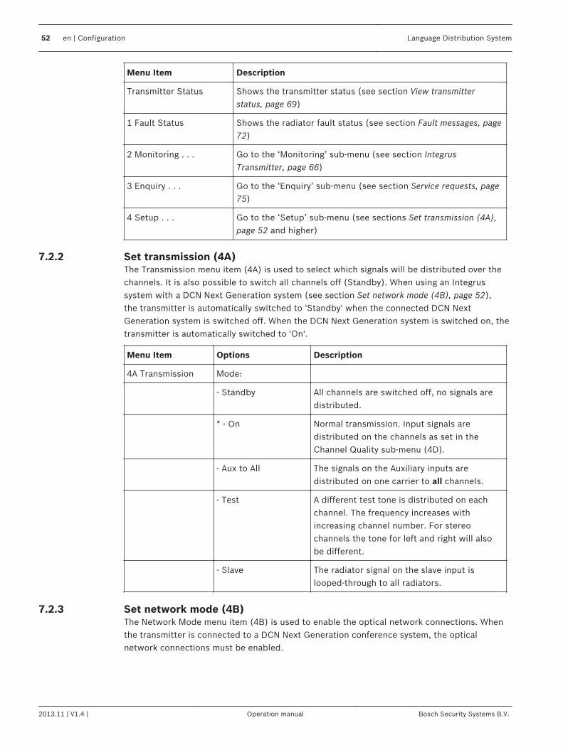
Menu Item Description
Transmitter Status Shows the transmitter status (see section View transmitterstatus, page 69)
1 Fault Status Shows the radiator fault status (see section Fault messages, page72)
2 Monitoring . . . Go to the ‘Monitoring’ sub-menu (see section IntegrusTransmitter, page 66)
3 Enquiry . . . Go to the ‘Enquiry’ sub-menu (see section Service requests, page75)
4 Setup . . . Go to the ‘Setup’ sub-menu (see sections Set transmission (4A),page 52 and higher)
Set transmission (4A)The Transmission menu item (4A) is used to select which signals will be distributed over thechannels. It is also possible to switch all channels off (Standby). When using an Integrussystem with a DCN Next Generation system (see section Set network mode (4B), page 52),the transmitter is automatically switched to 'Standby' when the connected DCN NextGeneration system is switched off. When the DCN Next Generation system is switched on, thetransmitter is automatically switched to 'On'.
Menu Item Options Description
4A Transmission Mode:
- Standby All channels are switched off, no signals aredistributed.
* - On Normal transmission. Input signals aredistributed on the channels as set in theChannel Quality sub-menu (4D).
- Aux to All The signals on the Auxiliary inputs aredistributed on one carrier to all channels.
- Test A different test tone is distributed on eachchannel. The frequency increases withincreasing channel number. For stereochannels the tone for left and right will alsobe different.
- Slave The radiator signal on the slave input islooped-through to all radiators.
Set network mode (4B)The Network Mode menu item (4B) is used to enable the optical network connections. Whenthe transmitter is connected to a DCN Next Generation conference system, the opticalnetwork connections must be enabled.
7.2.2
7.2.3
52 en | Configuration Language Distribution System
2013.11 | V1.4 | Operation manual Bosch Security Systems B.V.
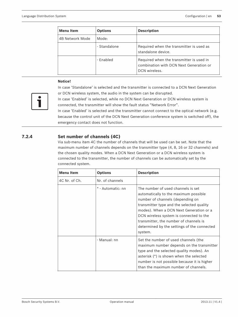
Menu Item Options Description
4B Network Mode Mode:
- Standalone Required when the transmitter is used asstandalone device.
- Enabled Required when the transmitter is used incombination with DCN Next Generation orDCN wireless.
Notice!
In case ‘Standalone’ is selected and the transmitter is connected to a DCN Next Generation
or DCN wireless system, the audio in the system can be disrupted.
In case ‘Enabled’ is selected, while no DCN Next Generation or DCN wireless system is
connected, the transmitter will show the fault status “Network Error”.
In case ‘Enabled’ is selected and the transmitter cannot connect to the optical network (e.g.
because the control unit of the DCN Next Generation conference system is switched off), the
emergency contact does not function.
Set number of channels (4C)Via sub-menu item 4C the number of channels that will be used can be set. Note that themaximum number of channels depends on the transmitter type (4, 8, 16 or 32 channels) andthe chosen quality modes. When a DCN Next Generation or a DCN wireless system isconnected to the transmitter, the number of channels can be automatically set by theconnected system.
Menu Item Options Description
4C Nr. of Ch. Nr. of channels
* - Automatic: nn The number of used channels is setautomatically to the maximum possiblenumber of channels (depending ontransmitter type and the selected qualitymodes). When a DCN Next Generation or aDCN wireless system is connected to thetransmitter, the number of channels isdetermined by the settings of the connectedsystem.
- Manual: nn Set the number of used channels (themaximum number depends on the transmittertype and the selected quality modes). Anasterisk (*) is shown when the selectednumber is not possible because it is higherthan the maximum number of channels.
7.2.4
Language Distribution System Configuration | en 53
Bosch Security Systems B.V. Operation manual 2013.11 | V1.4 |
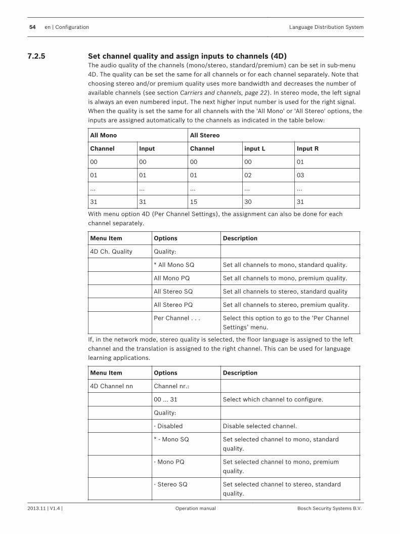
Set channel quality and assign inputs to channels (4D)The audio quality of the channels (mono/stereo, standard/premium) can be set in sub-menu4D. The quality can be set the same for all channels or for each channel separately. Note thatchoosing stereo and/or premium quality uses more bandwidth and decreases the number ofavailable channels (see section Carriers and channels, page 22). In stereo mode, the left signalis always an even numbered input. The next higher input number is used for the right signal.When the quality is set the same for all channels with the 'All Mono' or 'All Stereo' options, theinputs are assigned automatically to the channels as indicated in the table below:
All Mono All Stereo
Channel Input Channel input L Input R
00 00 00 00 01
01 01 01 02 03
... ... ... ... ...
31 31 15 30 31
With menu option 4D (Per Channel Settings), the assignment can also be done for eachchannel separately.
Menu Item Options Description
4D Ch. Quality Quality:
* All Mono SQ Set all channels to mono, standard quality.
All Mono PQ Set all channels to mono, premium quality.
All Stereo SQ Set all channels to stereo, standard quality
All Stereo PQ Set all channels to stereo, premium quality.
Per Channel . . . Select this option to go to the ‘Per ChannelSettings’ menu.
If, in the network mode, stereo quality is selected, the floor language is assigned to the leftchannel and the translation is assigned to the right channel. This can be used for languagelearning applications.
Menu Item Options Description
4D Channel nn Channel nr.:
00 ... 31 Select which channel to configure.
Quality:
- Disabled Disable selected channel.
* - Mono SQ Set selected channel to mono, standardquality.
- Mono PQ Set selected channel to mono, premiumquality.
- Stereo SQ Set selected channel to stereo, standardquality.
7.2.5
54 en | Configuration Language Distribution System
2013.11 | V1.4 | Operation manual Bosch Security Systems B.V.
Menu Item Options Description
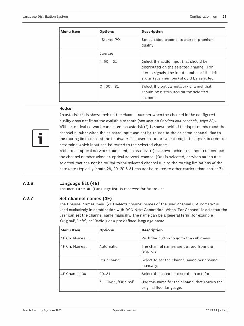
- Stereo PQ Set selected channel to stereo, premiumquality.
Source:
In 00 .. 31 Select the audio input that should bedistributed on the selected channel. Forstereo signals, the input number of the leftsignal (even number) should be selected.
On 00 .. 31 Select the optical network channel thatshould be distributed on the selectedchannel.
Notice!
An asterisk (*) is shown behind the channel number when the channel in the configured
quality does not fit on the available carriers (see section Carriers and channels, page 22).
With an optical network connected, an asterisk (*) is shown behind the input number and the
channel number when the selected input can not be routed to the selected channel, due to
the routing limitations of the hardware. The user has to browse through the inputs in order to
determine which input can be routed to the selected channel.
Without an optical network connected, an asterisk (*) is shown behind the input number and
the channel number when an optical network channel (On) is selected, or when an input is
selected that can not be routed to the selected channel due to the routing limitations of the
hardware (typically inputs 28, 29, 30 & 31 can not be routed to other carriers than carrier 7).
Language list (4E)The menu item 4E (Language list) is reserved for future use.
Set channel names (4F)The Channel Names menu (4F) selects channel names of the used channels. 'Automatic' isused exclusively in combination with DCN Next Generation. When 'Per Channel' is selected theuser can set the channel name manually. The name can be a general term (for example'Original', ‘Info’, or ‘Radio’) or a pre-defined language name.
Menu Item Options Description
4F Ch. Names ... Push the button to go to the sub-menu.
4F Ch. Names ... Automatic The channel names are derived from theDCN‑NG
Per channel ... Select to set the channel name per channelmanually.
4F Channel 00 00..31 Select the channel to set the name for.
* - ‘Floor’, ‘Original’ Use this name for the channel that carries theoriginal floor language.
7.2.6
7.2.7
Language Distribution System Configuration | en 55
Bosch Security Systems B.V. Operation manual 2013.11 | V1.4 |
Menu Item Options Description
- ‘Audio’, ‘Radio’, ‘TV’,‘Info’
Choose these names when the system is usedfor music distribution.
- language names Choose from pre-programmed languagenames (list shows abbreviation and theEnglish name of the language).
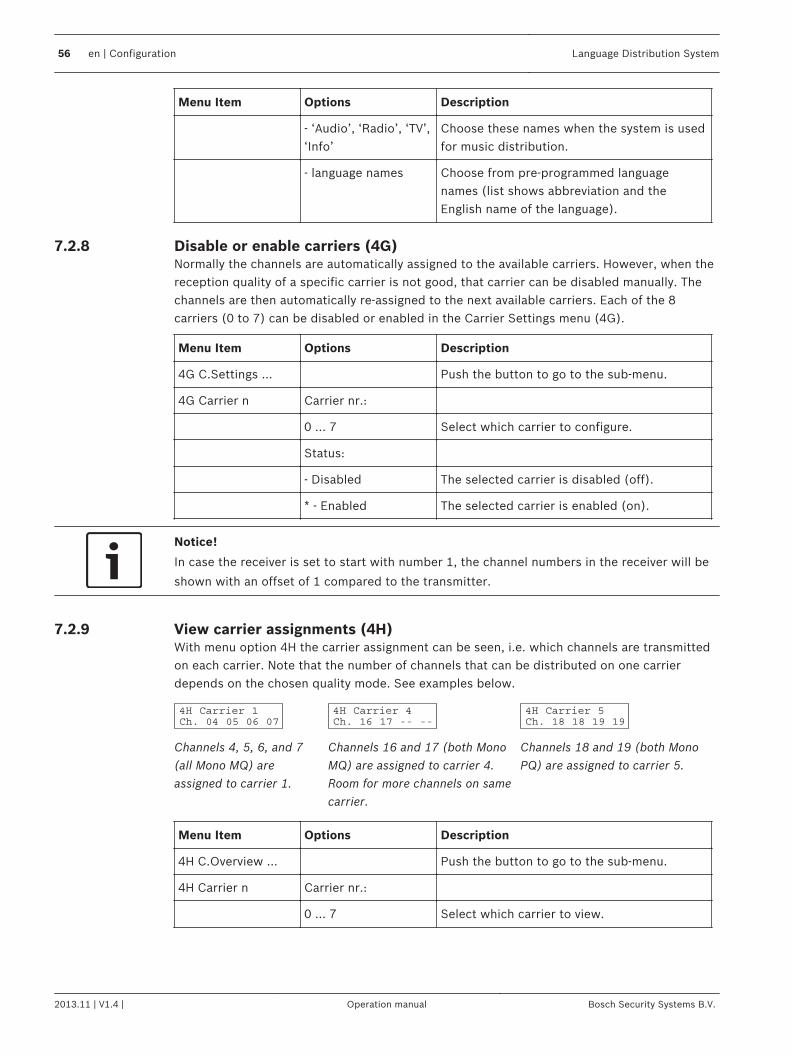
Disable or enable carriers (4G)Normally the channels are automatically assigned to the available carriers. However, when thereception quality of a specific carrier is not good, that carrier can be disabled manually. Thechannels are then automatically re-assigned to the next available carriers. Each of the 8carriers (0 to 7) can be disabled or enabled in the Carrier Settings menu (4G).
Menu Item Options Description
4G C.Settings ... Push the button to go to the sub-menu.
4G Carrier n Carrier nr.:
0 ... 7 Select which carrier to configure.
Status:
- Disabled The selected carrier is disabled (off).
* - Enabled The selected carrier is enabled (on).
Notice!
In case the receiver is set to start with number 1, the channel numbers in the receiver will be
shown with an offset of 1 compared to the transmitter.
View carrier assignments (4H)With menu option 4H the carrier assignment can be seen, i.e. which channels are transmittedon each carrier. Note that the number of channels that can be distributed on one carrierdepends on the chosen quality mode. See examples below.
Channels 4, 5, 6, and 7(all Mono MQ) areassigned to carrier 1.
Channels 16 and 17 (both MonoMQ) are assigned to carrier 4.Room for more channels on samecarrier.
Channels 18 and 19 (both MonoPQ) are assigned to carrier 5.
Menu Item Options Description
4H C.Overview ... Push the button to go to the sub-menu.
4H Carrier n Carrier nr.:
0 ... 7 Select which carrier to view.
7.2.8
7.2.9
56 en | Configuration Language Distribution System
2013.11 | V1.4 | Operation manual Bosch Security Systems B.V.
Menu Item Options Description
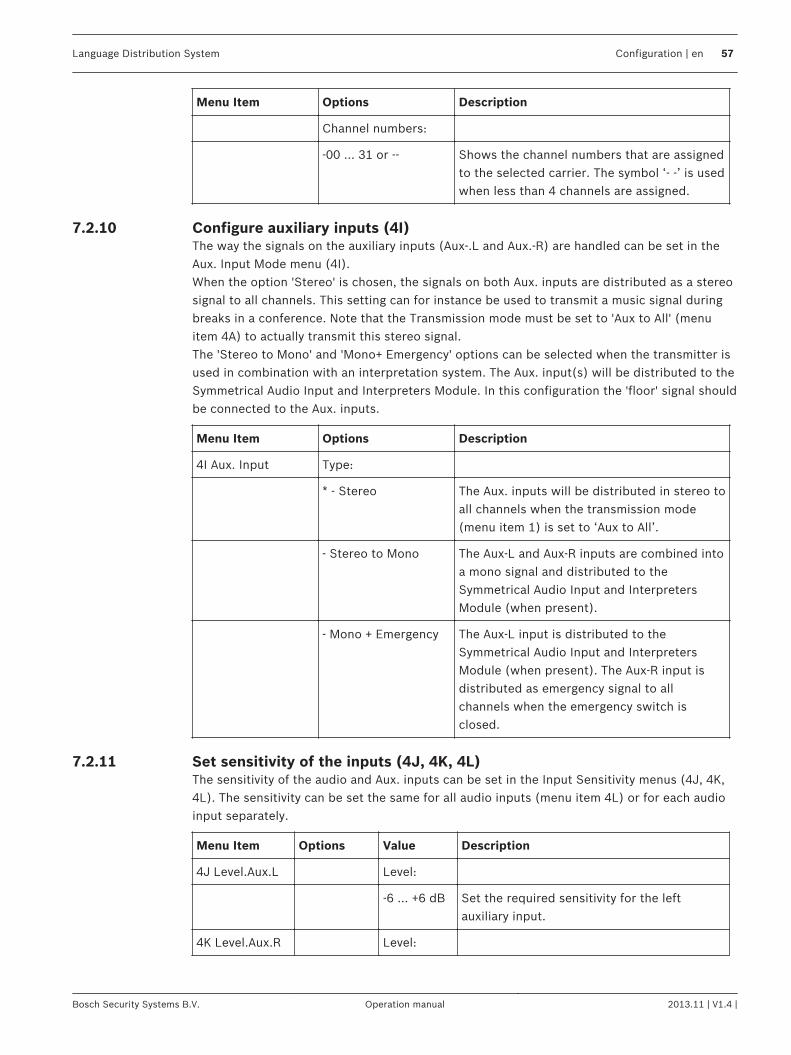
Channel numbers:
-00 ... 31 or -- Shows the channel numbers that are assignedto the selected carrier. The symbol ‘- -’ is usedwhen less than 4 channels are assigned.
Configure auxiliary inputs (4I)The way the signals on the auxiliary inputs (Aux-.L and Aux.-R) are handled can be set in theAux. Input Mode menu (4I).When the option 'Stereo' is chosen, the signals on both Aux. inputs are distributed as a stereosignal to all channels. This setting can for instance be used to transmit a music signal duringbreaks in a conference. Note that the Transmission mode must be set to 'Aux to All' (menuitem 4A) to actually transmit this stereo signal.The 'Stereo to Mono' and 'Mono+ Emergency' options can be selected when the transmitter isused in combination with an interpretation system. The Aux. input(s) will be distributed to theSymmetrical Audio Input and Interpreters Module. In this configuration the 'floor' signal shouldbe connected to the Aux. inputs.
Menu Item Options Description
4I Aux. Input Type:
* - Stereo The Aux. inputs will be distributed in stereo toall channels when the transmission mode(menu item 1) is set to ‘Aux to All’.
- Stereo to Mono The Aux-L and Aux-R inputs are combined intoa mono signal and distributed to theSymmetrical Audio Input and InterpretersModule (when present).
- Mono + Emergency The Aux-L input is distributed to theSymmetrical Audio Input and InterpretersModule (when present). The Aux-R input isdistributed as emergency signal to allchannels when the emergency switch isclosed.
Set sensitivity of the inputs (4J, 4K, 4L)The sensitivity of the audio and Aux. inputs can be set in the Input Sensitivity menus (4J, 4K,4L). The sensitivity can be set the same for all audio inputs (menu item 4L) or for each audioinput separately.
Menu Item Options Value Description
4J Level.Aux.L Level:
-6 ... +6 dB Set the required sensitivity for the leftauxiliary input.
4K Level.Aux.R Level:
7.2.10
7.2.11
Language Distribution System Configuration | en 57
Bosch Security Systems B.V. Operation manual 2013.11 | V1.4 |
Menu Item Options Value Description
-6 ... +6 dB Set the required sensitivity for the rightauxiliary input.
4L Level Inputs Mode: Level:
- All -6 ... +6 dB Set the sensitivity of all audio inputs to a userdefined level.
- Per Input ... Select this option to go to the ‘Per InputSensitivity Settings’ menu.
The sensitivity screens also displays a level meter for a visual indication of the actual signal
strength: = low level, = high level, = overflow.
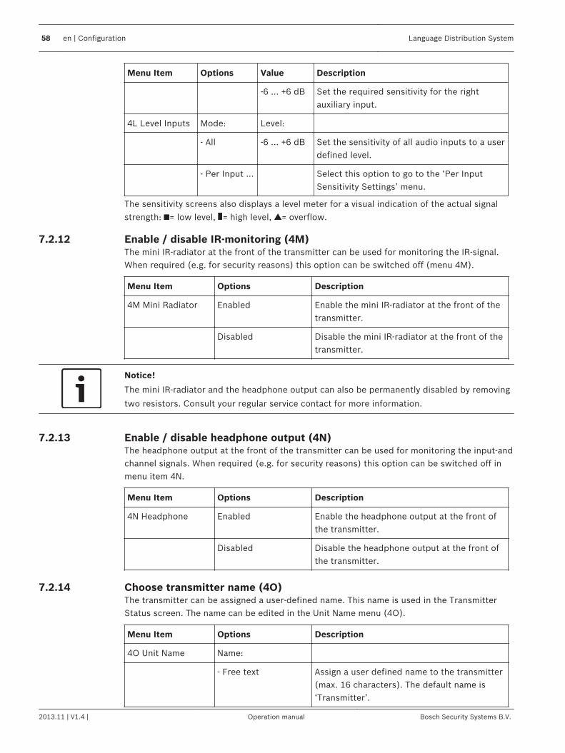
Enable / disable IR-monitoring (4M)The mini IR-radiator at the front of the transmitter can be used for monitoring the IR-signal.When required (e.g. for security reasons) this option can be switched off (menu 4M).
Menu Item Options Description
4M Mini Radiator Enabled Enable the mini IR-radiator at the front of thetransmitter.
Disabled Disable the mini IR-radiator at the front of thetransmitter.
Notice!
The mini IR-radiator and the headphone output can also be permanently disabled by removing
two resistors. Consult your regular service contact for more information.
Enable / disable headphone output (4N)The headphone output at the front of the transmitter can be used for monitoring the input-andchannel signals. When required (e.g. for security reasons) this option can be switched off inmenu item 4N.
Menu Item Options Description
4N Headphone Enabled Enable the headphone output at the front ofthe transmitter.
Disabled Disable the headphone output at the front ofthe transmitter.
Choose transmitter name (4O)The transmitter can be assigned a user-defined name. This name is used in the TransmitterStatus screen. The name can be edited in the Unit Name menu (4O).
Menu Item Options Description
4O Unit Name Name:
- Free text Assign a user defined name to the transmitter(max. 16 characters). The default name is‘Transmitter’.
7.2.12
7.2.13
7.2.14
58 en | Configuration Language Distribution System
2013.11 | V1.4 | Operation manual Bosch Security Systems B.V.
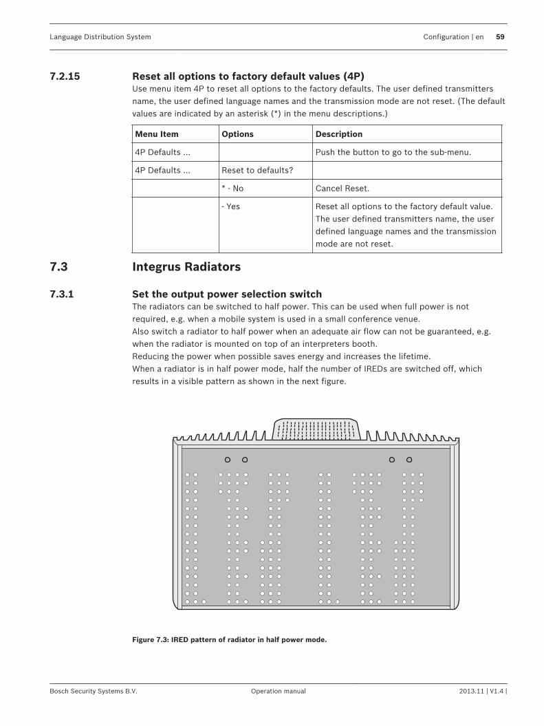
Reset all options to factory default values (4P)Use menu item 4P to reset all options to the factory defaults. The user defined transmittersname, the user defined language names and the transmission mode are not reset. (The defaultvalues are indicated by an asterisk (*) in the menu descriptions.)
Menu Item Options Description
4P Defaults ... Push the button to go to the sub-menu.
4P Defaults ... Reset to defaults?
* - No Cancel Reset.
- Yes Reset all options to the factory default value.The user defined transmitters name, the userdefined language names and the transmissionmode are not reset.
Integrus Radiators
Set the output power selection switchThe radiators can be switched to half power. This can be used when full power is notrequired, e.g. when a mobile system is used in a small conference venue.Also switch a radiator to half power when an adequate air flow can not be guaranteed, e.g.when the radiator is mounted on top of an interpreters booth.Reducing the power when possible saves energy and increases the lifetime.When a radiator is in half power mode, half the number of IREDs are switched off, whichresults in a visible pattern as shown in the next figure.
Figure 7.3: IRED pattern of radiator in half power mode.
7.2.15
7.3
7.3.1
Language Distribution System Configuration | en 59
Bosch Security Systems B.V. Operation manual 2013.11 | V1.4 |
Set the delay switchesRefer to Determine the radiator delay switch positions, page 60 how to determine the radiatordelay switch positions.
!
Caution!
Turn the delay switches carefully to a new position until you feel that it clicks into position, to
prevent that a switch is positioned between two numbers, which would result in a wrong
delay setting.
Determine the radiator delay switch positionsAs described in section Overlapping footprints and black spots, page 29, differences in thedelays of the signals picked up by the receiver from two or more radiators can cause blackspots as a result of the multi path effect.The signals picked up by the receiver are delayed by:– the transmission from transmitter to radiator through the cable (cable signal delay)– the transmission from radiator to receiver through the air (radiation signal delay)– for systems with two or more transmitters: the transmission through the slave
transmitter(s)To compensate the signal delay differences, the delay of each radiator can be increased.These signal delays can be set with the delay switches at the back of the radiator.The cable signal delays can be determined in the following two ways:– by measuring the cable lengths– by measuring the impulse response time with a delay measurement toolIn both cases the cable signal delays can be calculated manually and with the delay switchcalculation tool (available on the documentation DVD).It is not necessary to calculate the cable signal delay in case:– the radiators are directly connected to the transmitter with equal cable length;– radiators are loop-through connected, but with less than 5 m distance between the first
and last radiator in a trunk, and with equal cable length between the first radiator in eachtrunk and the transmitter.
In these cases set the delay switches on all radiators to zero and determine whether tocompensate for radiation signal delay (see section Systems with more than 4 carriers and aradiator under a balcony, page 65).The next sections describe how to calculate the delay switch positions manually for systemswith one transmitter, or two or more transmitters. See the delay switch calculation tool forthe procedures how to calculate the delay switch positions automatically.
Notice!
The delay switch calculation tool eases the calculation of the delay switch positions.
System with one transmitterThere are two ways to determine the delay switch positions:– Measuring the cable lengths– Using a delay measuring toolBoth methods are described in the next sections.
7.3.2
7.4
7.4.1
60 en | Configuration Language Distribution System
2013.11 | V1.4 | Operation manual Bosch Security Systems B.V.
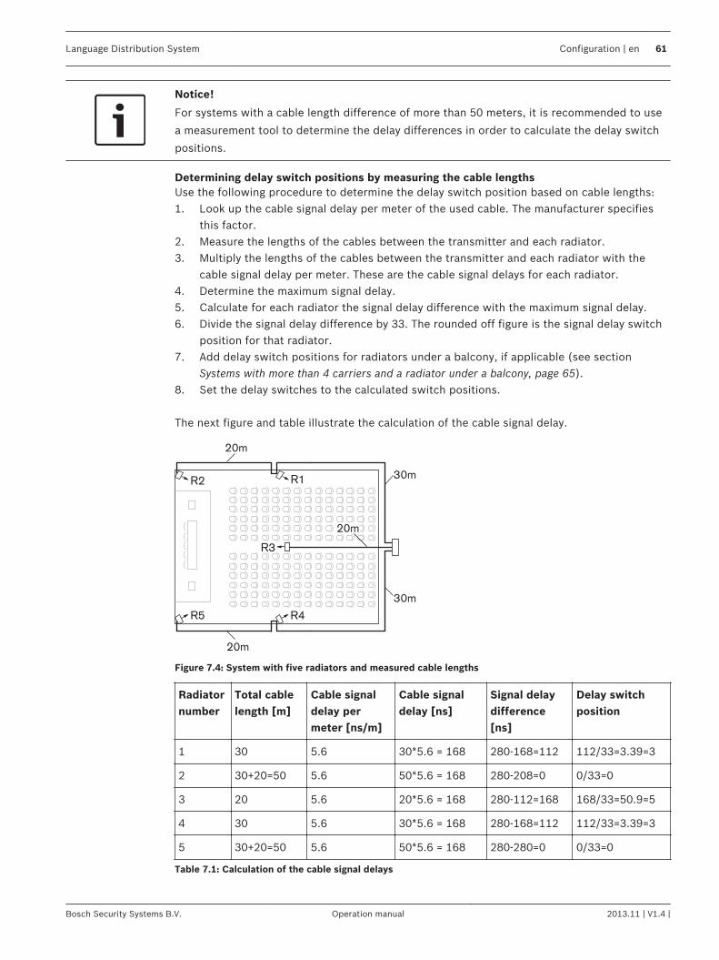
Notice!
For systems with a cable length difference of more than 50 meters, it is recommended to use
a measurement tool to determine the delay differences in order to calculate the delay switch
positions.
Determining delay switch positions by measuring the cable lengthsUse the following procedure to determine the delay switch position based on cable lengths:1. Look up the cable signal delay per meter of the used cable. The manufacturer specifies
this factor.2. Measure the lengths of the cables between the transmitter and each radiator.3. Multiply the lengths of the cables between the transmitter and each radiator with the
cable signal delay per meter. These are the cable signal delays for each radiator.4. Determine the maximum signal delay.5. Calculate for each radiator the signal delay difference with the maximum signal delay.6. Divide the signal delay difference by 33. The rounded off figure is the signal delay switch
position for that radiator.7. Add delay switch positions for radiators under a balcony, if applicable (see section
Systems with more than 4 carriers and a radiator under a balcony, page 65).8. Set the delay switches to the calculated switch positions. The next figure and table illustrate the calculation of the cable signal delay.
20m
20m
30m
30m
R2
R5 R4
R3
R1
20m
Figure 7.4: System with five radiators and measured cable lengths
Radiatornumber
Total cablelength [m]
Cable signaldelay permeter [ns/m]
Cable signaldelay [ns]
Signal delaydifference[ns]
Delay switchposition
1 30 5.6 30*5.6 = 168 280-168=112 112/33=3.39=3
2 30+20=50 5.6 50*5.6 = 168 280-208=0 0/33=0
3 20 5.6 20*5.6 = 168 280-112=168 168/33=50.9=5
4 30 5.6 30*5.6 = 168 280-168=112 112/33=3.39=3
5 30+20=50 5.6 50*5.6 = 168 280-280=0 0/33=0
Table 7.1: Calculation of the cable signal delays
Language Distribution System Configuration | en 61
Bosch Security Systems B.V. Operation manual 2013.11 | V1.4 |
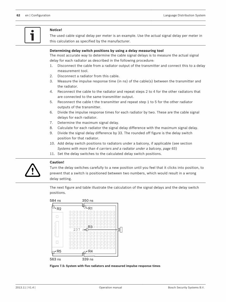
Notice!
The used cable signal delay per meter is an example. Use the actual signal delay per meter in
this calculation as specified by the manufacturer.
Determining delay switch positions by using a delay measuring toolThe most accurate way to determine the cable signal delays is to measure the actual signaldelay for each radiator as described in the following procedure:1. Disconnect the cable from a radiator output of the transmitter and connect this to a delay
measurement tool.2. Disconnect a radiator from this cable.3. Measure the impulse response time (in ns) of the cable(s) between the transmitter and
the radiator.4. Reconnect the cable to the radiator and repeat steps 2 to 4 for the other radiators that
are connected to the same transmitter output.5. Reconnect the cable t the transmitter and repeat step 1 to 5 for the other radiator
outputs of the transmitter.6. Divide the impulse response times for each radiator by two. These are the cable signal
delays for each radiator.7. Determine the maximum signal delay.8. Calculate for each radiator the signal delay difference with the maximum signal delay.9. Divide the signal delay difference by 33. The rounded off figure is the delay switch
position for that radiator.10. Add delay switch positions to radiators under a balcony, if applicable (see section
Systems with more than 4 carriers and a radiator under a balcony, page 65)11. Set the delay switches to the calculated delay switch positions.
!
Caution!
Turn the delay switches carefully to a new position until you feel that it clicks into position, to
prevent that a switch is positioned between two numbers, which would result in a wrong
delay setting.
The next figure and table illustrate the calculation of the signal delays and the delay switchpositions.
584 ns 350 ns
563 ns 339 ns
R2
R5 R4
237 ns
R1
R3
Figure 7.5: System with five radiators and measured impulse response times
62 en | Configuration Language Distribution System
2013.11 | V1.4 | Operation manual Bosch Security Systems B.V.
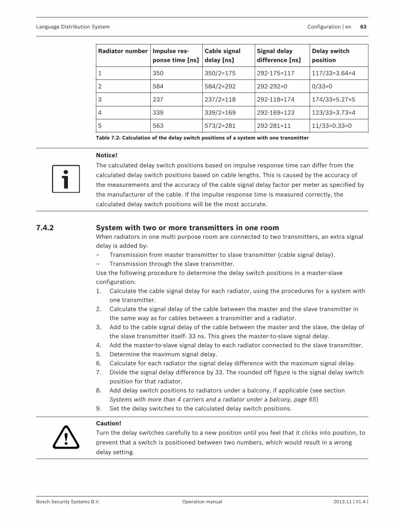
Radiator number Impulse res-ponse time [ns]
Cable signaldelay [ns]
Signal delaydifference [ns]
Delay switchposition
1 350 350/2=175 292-175=117 117/33=3.64=4
2 584 584/2=292 292-292=0 0/33=0
3 237 237/2=118 292-118=174 174/33=5.27=5
4 339 339/2=169 292-169=123 123/33=3.73=4
5 563 573/2=281 292-281=11 11/33=0.33=0
Table 7.2: Calculation of the delay switch positions of a system with one transmitter
Notice!
The calculated delay switch positions based on impulse response time can differ from the
calculated delay switch positions based on cable lengths. This is caused by the accuracy of
the measurements and the accuracy of the cable signal delay factor per meter as specified by
the manufacturer of the cable. If the impulse response time is measured correctly, the
calculated delay switch positions will be the most accurate.
System with two or more transmitters in one roomWhen radiators in one multi purpose room are connected to two transmitters, an extra signaldelay is added by:– Transmission from master transmitter to slave transmitter (cable signal delay).– Transmission through the slave transmitter.Use the following procedure to determine the delay switch positions in a master-slaveconfiguration:1. Calculate the cable signal delay for each radiator, using the procedures for a system with
one transmitter.2. Calculate the signal delay of the cable between the master and the slave transmitter in
the same way as for cables between a transmitter and a radiator.3. Add to the cable signal delay of the cable between the master and the slave, the delay of
the slave transmitter itself: 33 ns. This gives the master-to-slave signal delay.4. Add the master-to-slave signal delay to each radiator connected to the slave transmitter.5. Determine the maximum signal delay.6. Calculate for each radiator the signal delay difference with the maximum signal delay.7. Divide the signal delay difference by 33. The rounded off figure is the signal delay switch
position for that radiator.8. Add delay switch positions to radiators under a balcony, if applicable (see section
Systems with more than 4 carriers and a radiator under a balcony, page 65)9. Set the delay switches to the calculated delay switch positions.
!
Caution!
Turn the delay switches carefully to a new position until you feel that it clicks into position, to
prevent that a switch is positioned between two numbers, which would result in a wrong
delay setting.
7.4.2
Language Distribution System Configuration | en 63
Bosch Security Systems B.V. Operation manual 2013.11 | V1.4 |
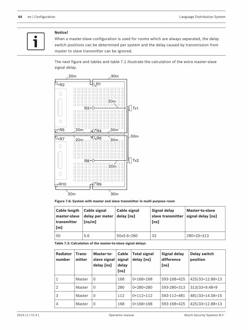
Notice!
When a master-slave configuration is used for rooms which are always separated, the delay
switch positions can be determined per system and the delay caused by transmission from
master to slave transmitter can be ignored.
The next figure and tables and table 7.1 illustrate the calculation of the extra master-slavesignal delay.
R2 R1
R4
R6
R9
20m
R7
R5
R10
Tx2R8
R3 Tx1
20m
30m
20m
50m
30m20m
20m
30m
30m
20m
Figure 7.6: System with master and slave transmitter in multi purpose room
Cable lengthmaster-slavetransmitter[m]
Cable signaldelay per meter[ns/m]
Cable signaldelay [ns]
Signal delayslave transmitter[ns]
Master-to-slavesignal delay [ns]
50 5.6 50x5.6=280 33 280+33=313
Table 7.3: Calculation of the master-to-slave signal delays
Radiatornumber
Trans-mitter
Master-to-slave signaldelay [ns]
Cablesignaldelay[ns]
Total signaldelay [ns]
Signal delaydifference[ns]
Delay switchposition
1 Master 0 168 0+168=168 593-168=425 425/33=12.88=13
2 Master 0 280 0+280=280 593-280=313 313/33=9.48=9
3 Master 0 112 0+112=112 593-112=481 481/33=14.58=15
4 Master 0 168 0+168=168 593-168=425 425/33=12.88=13
64 en | Configuration Language Distribution System
2013.11 | V1.4 | Operation manual Bosch Security Systems B.V.
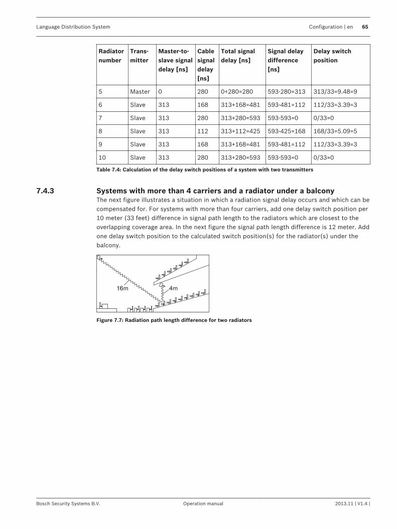
Radiatornumber
Trans-mitter
Master-to-slave signaldelay [ns]
Cablesignaldelay[ns]
Total signaldelay [ns]
Signal delaydifference[ns]
Delay switchposition
5 Master 0 280 0+280=280 593-280=313 313/33=9.48=9
6 Slave 313 168 313+168=481 593-481=112 112/33=3.39=3
7 Slave 313 280 313+280=593 593-593=0 0/33=0
8 Slave 313 112 313+112=425 593-425=168 168/33=5.09=5
9 Slave 313 168 313+168=481 593-481=112 112/33=3.39=3
10 Slave 313 280 313+280=593 593-593=0 0/33=0
Table 7.4: Calculation of the delay switch positions of a system with two transmitters
Systems with more than 4 carriers and a radiator under a balconyThe next figure illustrates a situation in which a radiation signal delay occurs and which can becompensated for. For systems with more than four carriers, add one delay switch position per10 meter (33 feet) difference in signal path length to the radiators which are closest to theoverlapping coverage area. In the next figure the signal path length difference is 12 meter. Addone delay switch position to the calculated switch position(s) for the radiator(s) under thebalcony.
16m 4m
Figure 7.7: Radiation path length difference for two radiators
7.4.3
Language Distribution System Configuration | en 65
Bosch Security Systems B.V. Operation manual 2013.11 | V1.4 |
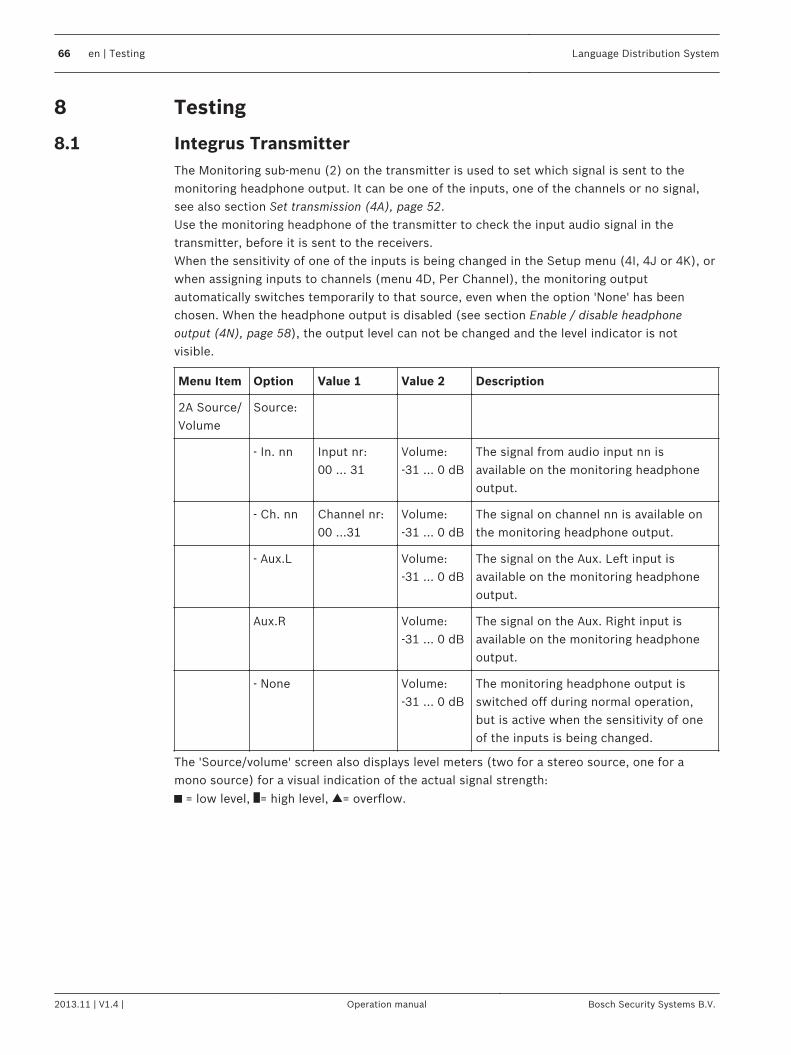
Testing
Integrus TransmitterThe Monitoring sub-menu (2) on the transmitter is used to set which signal is sent to themonitoring headphone output. It can be one of the inputs, one of the channels or no signal,see also section Set transmission (4A), page 52.Use the monitoring headphone of the transmitter to check the input audio signal in thetransmitter, before it is sent to the receivers.When the sensitivity of one of the inputs is being changed in the Setup menu (4I, 4J or 4K), orwhen assigning inputs to channels (menu 4D, Per Channel), the monitoring outputautomatically switches temporarily to that source, even when the option 'None' has beenchosen. When the headphone output is disabled (see section Enable / disable headphoneoutput (4N), page 58), the output level can not be changed and the level indicator is notvisible.
Menu Item Option Value 1 Value 2 Description
2A Source/Volume
Source:
- In. nn Input nr:00 ... 31
Volume:-31 ... 0 dB
The signal from audio input nn isavailable on the monitoring headphoneoutput.
- Ch. nn Channel nr:00 ...31
Volume:-31 ... 0 dB
The signal on channel nn is available onthe monitoring headphone output.
- Aux.L Volume:-31 ... 0 dB
The signal on the Aux. Left input isavailable on the monitoring headphoneoutput.
Aux.R Volume:-31 ... 0 dB
The signal on the Aux. Right input isavailable on the monitoring headphoneoutput.
- None Volume:-31 ... 0 dB
The monitoring headphone output isswitched off during normal operation,but is active when the sensitivity of oneof the inputs is being changed.
The 'Source/volume' screen also displays level meters (two for a stereo source, one for amono source) for a visual indication of the actual signal strength:
= low level, = high level, = overflow.
8
8.1
66 en | Testing Language Distribution System
2013.11 | V1.4 | Operation manual Bosch Security Systems B.V.
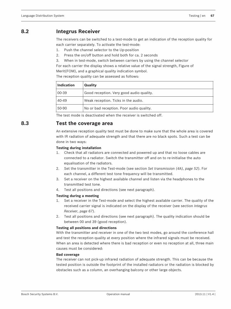
Integrus ReceiverThe receivers can be switched to a test‑mode to get an indication of the reception quality foreach carrier separately. To activate the test-mode:1. Push the channel selector to the Up‑position2. Press the on/off button and hold both for ca. 2 seconds3. When in test-mode, switch between carriers by using the channel selectorFor each carrier the display shows a relative value of the signal strength, Figure ofMerit(FOM), and a graphical quality indication symbol.The reception quality can be assessed as follows:
Indication Quality
00-39 Good reception. Very good audio quality.
40-49 Weak reception. Ticks in the audio.
50-90 No or bad reception. Poor audio quality.
The test mode is deactivated when the receiver is switched off.
Test the coverage areaAn extensive reception quality test must be done to make sure that the whole area is coveredwith IR radiation of adequate strength and that there are no black spots. Such a test can bedone in two ways:
Testing during installation1. Check that all radiators are connected and powered up and that no loose cables are
connected to a radiator. Switch the transmitter off and on to re-initialise the autoequalisation of the radiators.
2. Set the transmitter in the Test-mode (see section Set transmission (4A), page 52). Foreach channel, a different test tone frequency will be transmitted.
3. Set a receiver on the highest available channel and listen via the headphones to thetransmitted test tone.
4. Test all positions and directions (see next paragraph).
Testing during a meeting1. Set a receiver in the Test-mode and select the highest available carrier. The quality of the
received carrier signal is indicated on the display of the receiver (see section IntegrusReceiver, page 67).
2. Test all positions and directions (see next paragraph). The quality indication should bebetween 00 and 39 (good reception).
Testing all positions and directionsWith the transmitter and receiver in one of the two test modes, go around the conference halland test the reception quality at every position where the infrared signals must be received.When an area is detected where there is bad reception or even no reception at all, three maincauses must be considered:
Bad coverageThe receiver can not pick-up infrared radiation of adequate strength. This can be because thetested position is outside the footprint of the installed radiators or the radiation is blocked byobstacles such as a column, an overhanging balcony or other large objects.
8.2
8.3
Language Distribution System Testing | en 67
Bosch Security Systems B.V. Operation manual 2013.11 | V1.4 |
Check that you used the correct footprints for the system design, that radiators with enoughoutput power are installed and that a radiator is not accidentally switched to half poweroperation. When the bad reception is caused by a blocked radiation path, try to remove theblocking obstacle or add an extra radiator to cover the shaded area.
Black spotsThe receiver picks-up IR signals from two radiators which cancel out each other.The black spot can be identified by the observation that the bad reception only occurs along aspecific line and/or when good reception returns when the receiver is rotated to anotherdirection. This can be confirmed by keeping the receiver in the position and direction with thebad reception and then either shading-off the radiation from one radiator with your hand orswitching off one radiator. If this improves the reception quality, then the black spot iscausing the problem. Note that IR radiation that is reflected from a surface with a highreflectively can also cause black spots.Black spots can occur in case a transmitter is located in the same room as the radiators.– In that case, disable the mini IR radiator of the transmitter with the configuration menu
(see section Enable / disable IR-monitoring (4M), page 58).– Check that the signal delay compensation switches on the radiators are set to the correct
value and that a switch is not accidentally positioned between two numbers.– Re-check your system design. When necessary, reduce the distance between the two
radiators that cause the problem and/or add an extra radiator.Note that due to the physical characteristics of the signal distribution, it is not always possibleto completely avoid black spots.
Interference from IR systemsIR assisted hearing systems and IR microphones operating at frequencies above 2 MHz, candisturb the reception at the lowest carriers. If such is the case, disable the lowest two carriers(see section Disable or enable carriers (4G), page 56) and re-check the reception.
68 en | Testing Language Distribution System
2013.11 | V1.4 | Operation manual Bosch Security Systems B.V.
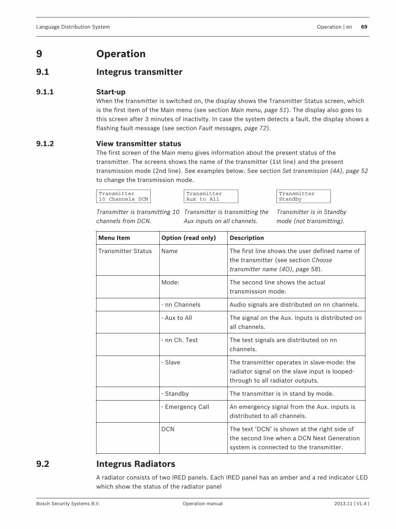
Operation
Integrus transmitter
Start-upWhen the transmitter is switched on, the display shows the Transmitter Status screen, whichis the first item of the Main menu (see section Main menu, page 51). The display also goes tothis screen after 3 minutes of inactivity. In case the system detects a fault, the display shows aflashing fault message (see section Fault messages, page 72).
View transmitter statusThe first screen of the Main menu gives information about the present status of thetransmitter. The screens shows the name of the transmitter (1st line) and the presenttransmission mode (2nd line). See examples below. See section Set transmission (4A), page 52to change the transmission mode.
Transmitter is transmitting 10channels from DCN.
Transmitter is transmitting theAux inputs on all channels.
Transmitter is in Standbymode (not transmitting).
Menu Item Option (read only) Description
Transmitter Status Name The first line shows the user defined name ofthe transmitter (see section Choosetransmitter name (4O), page 58).
Mode: The second line shows the actualtransmission mode:
- nn Channels Audio signals are distributed on nn channels.
- Aux to All The signal on the Aux. inputs is distributed onall channels.
- nn Ch. Test The test signals are distributed on nnchannels.
- Slave The transmitter operates in slave-mode: theradiator signal on the slave input is looped-through to all radiator outputs.
- Standby The transmitter is in stand by mode.
- Emergency Call An emergency signal from the Aux. inputs isdistributed to all channels.
DCN The text ‘DCN’ is shown at the right side ofthe second line when a DCN Next Generationsystem is connected to the transmitter.
Integrus RadiatorsA radiator consists of two IRED panels. Each IRED panel has an amber and a red indicator LEDwhich show the status of the radiator panel
9
9.1
9.1.1
9.1.2
9.2
Language Distribution System Operation | en 69
Bosch Security Systems B.V. Operation manual 2013.11 | V1.4 |
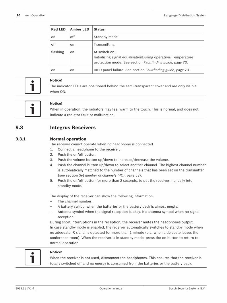
Red LED Amber LED Status
on off Standby mode
off on Transmitting
flashing on At switch-on:Initializing signal equalisationDuring operation: Temperatureprotection mode. See section Faultfinding guide, page 73.
on on IRED panel failure. See section Faultfinding guide, page 73.
Notice!
The indicator LEDs are positioned behind the semi-transparent cover and are only visible
when ON.
Notice!
When in operation, the radiators may feel warm to the touch. This is normal, and does not
indicate a radiator fault or malfunction.
Integrus Receivers
Normal operationThe receiver cannot operate when no headphone is connected.1. Connect a headphone to the receiver.2. Push the on/off button.3. Push the volume button up/down to increase/decrease the volume.4. Push the channel button up/down to select another channel. The highest channel number
is automatically matched to the number of channels that has been set on the transmitter(see section Set number of channels (4C), page 53).
5. Push the on/off button for more than 2 seconds, to put the receiver manually intostandby mode.
The display of the receiver can show the following information:– The channel number.– A battery symbol when the batteries or the battery pack is almost empty.– Antenna symbol when the signal reception is okay. No antenna symbol when no signal
reception.During short interruptions in the reception, the receiver mutes the headphones output.In case standby mode is enabled, the receiver automatically switches to standby mode whenno adequate IR signal is detected for more than 1 minute (e.g. when a delegate leaves theconference room). When the receiver is in standby mode, press the on button to return tonormal operation.
Notice!
When the receiver is not used, disconnect the headphones. This ensures that the receiver is
totally switched off and no energy is consumed from the batteries or the battery pack.
9.3
9.3.1
70 en | Operation Language Distribution System
2013.11 | V1.4 | Operation manual Bosch Security Systems B.V.
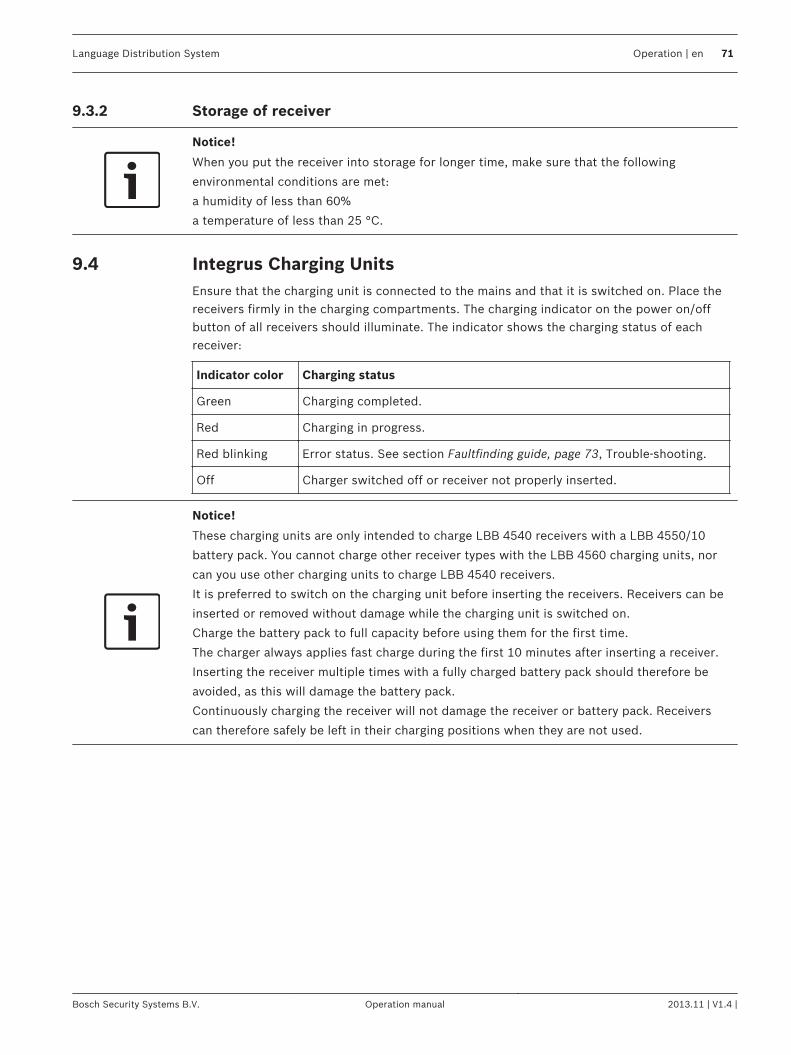
Storage of receiver
Notice!
When you put the receiver into storage for longer time, make sure that the following
environmental conditions are met:
a humidity of less than 60%
a temperature of less than 25 °C.
Integrus Charging UnitsEnsure that the charging unit is connected to the mains and that it is switched on. Place thereceivers firmly in the charging compartments. The charging indicator on the power on/offbutton of all receivers should illuminate. The indicator shows the charging status of eachreceiver:
Indicator color Charging status
Green Charging completed.
Red Charging in progress.
Red blinking Error status. See section Faultfinding guide, page 73, Trouble-shooting.
Off Charger switched off or receiver not properly inserted.
Notice!
These charging units are only intended to charge LBB 4540 receivers with a LBB 4550/10
battery pack. You cannot charge other receiver types with the LBB 4560 charging units, nor
can you use other charging units to charge LBB 4540 receivers.
It is preferred to switch on the charging unit before inserting the receivers. Receivers can be
inserted or removed without damage while the charging unit is switched on.
Charge the battery pack to full capacity before using them for the first time.
The charger always applies fast charge during the first 10 minutes after inserting a receiver.
Inserting the receiver multiple times with a fully charged battery pack should therefore be
avoided, as this will damage the battery pack.
Continuously charging the receiver will not damage the receiver or battery pack. Receivers
can therefore safely be left in their charging positions when they are not used.
9.3.2
9.4
Language Distribution System Operation | en 71
Bosch Security Systems B.V. Operation manual 2013.11 | V1.4 |
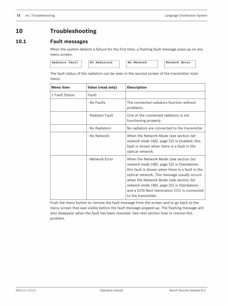
Troubleshooting
Fault messagesWhen the system detects a failure for the first time, a flashing fault message pops-up on anymenu screen:
The fault status of the radiators can be seen in the second screen of the transmitter mainmenu:
Menu Item Value (read only) Description
1 Fault Status Fault:
- No Faults The connected radiators function withoutproblems.
- Radiator Fault One of the connected radiators is notfunctioning properly.
- No Radiators No radiators are connected to the transmitter
- No Network When the Network Mode (see section Setnetwork mode (4B), page 52) is Enabled, thisfault is shown when there is a fault in theoptical network.
- Network Error When the Network Mode (see section Setnetwork mode (4B), page 52) is Standalone,this fault is shown when there is a fault in theoptical network. This message usually occurswhen the Network Mode (see section Setnetwork mode (4B), page 52) is Standalone,and a DCN Next Generation CCU is connectedto the transmitter.
Push the menu button to remove the fault message from the screen and to go back to themenu screen that was visible before the fault message popped-up. The flashing message willalso disappear when the fault has been resolved. See next section how to resolve thisproblem.
10
10.1
72 en | Troubleshooting Language Distribution System
2013.11 | V1.4 | Operation manual Bosch Security Systems B.V.
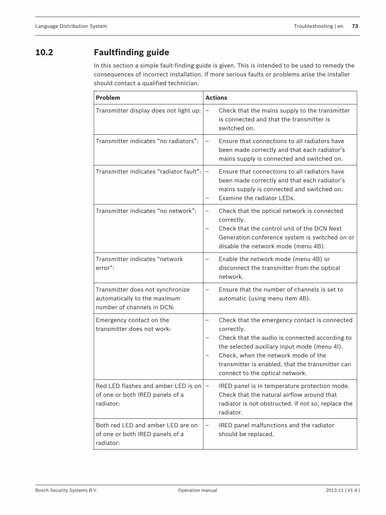
Faultfinding guideIn this section a simple fault-finding guide is given. This is intended to be used to remedy theconsequences of incorrect installation. If more serious faults or problems arise the installershould contact a qualified technician.
Problem Actions
Transmitter display does not light up: – Check that the mains supply to the transmitteris connected and that the transmitter isswitched on.
Transmitter indicates “no radiators”: – Ensure that connections to all radiators havebeen made correctly and that each radiator’smains supply is connected and switched on.
Transmitter indicates “radiator fault”: – Ensure that connections to all radiators havebeen made correctly and that each radiator’smains supply is connected and switched on.
– Examine the radiator LEDs.
Transmitter indicates “no network”: – Check that the optical network is connectedcorrectly.
– Check that the control unit of the DCN NextGeneration conference system is switched on ordisable the network mode (menu 4B).
Transmitter indicates “networkerror”:
– Enable the network mode (menu 4B) ordisconnect the transmitter from the opticalnetwork.
Transmitter does not synchronizeautomatically to the maximumnumber of channels in DCN:
– Ensure that the number of channels is set toautomatic (using menu item 4B).
Emergency contact on thetransmitter does not work:
– Check that the emergency contact is connectedcorrectly.
– Check that the audio is connected according tothe selected auxiliary input mode (menu 4I).
– Check, when the network mode of thetransmitter is enabled, that the transmitter canconnect to the optical network.
Red LED flashes and amber LED is onof one or both IRED panels of aradiator:
– IRED panel is in temperature protection mode.Check that the natural airflow around thatradiator is not obstructed. If not so, replace theradiator.
Both red LED and amber LED are onof one or both IRED panels of aradiator:
– IRED panel malfunctions and the radiatorshould be replaced.
10.2
Language Distribution System Troubleshooting | en 73
Bosch Security Systems B.V. Operation manual 2013.11 | V1.4 |
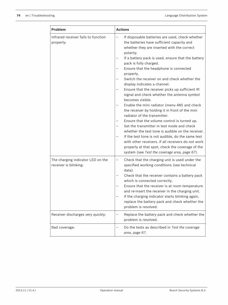
Problem Actions
Infrared receiver fails to functionproperly:
– If disposable batteries are used, check whetherthe batteries have sufficient capacity andwhether they are inserted with the correctpolarity.
– If a battery pack is used, ensure that the batterypack is fully charged.
– Ensure that the headphone is connectedproperly.
– Switch the receiver on and check whether thedisplay indicates a channel.
– Ensure that the receiver picks up sufficient IRsignal and check whether the antenna symbolbecomes visible.
– Enable the mini radiator (menu 4M) and checkthe receiver by holding it in front of the miniradiator of the transmitter.
– Ensure that the volume control is turned up.– Set the transmitter in test mode and check
whether the test tone is audible on the receiver.– If the test tone is not audible, do the same test
with other receivers. If all receivers do not workproperly at that spot, check the coverage of thesystem (see Test the coverage area, page 67).
The charging indicator LED on thereceiver is blinking:
– Check that the charging unit is used under thespecified working conditions (see technicaldata).
– Check that the receiver contains a battery packwhich is connected correctly.
– Ensure that the receiver is at room temperatureand re-insert the receiver in the charging unit.
– If the charging indicator starts blinking again,replace the battery pack and check whether theproblem is resolved.
Receiver discharges very quickly: – Replace the battery pack and check whether theproblem is resolved.
Bad coverage: – Do the tests as described in Test the coveragearea, page 67.
74 en | Troubleshooting Language Distribution System
2013.11 | V1.4 | Operation manual Bosch Security Systems B.V.
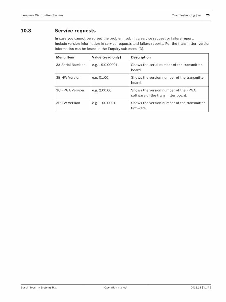
Service requestsIn case you cannot be solved the problem, submit a service request or failure report.Include version information in service requests and failure reports. For the transmitter, versioninformation can be found in the Enquiry sub-menu (3).
Menu Item Value (read only) Description
3A Serial Number e.g. 19.0.00001 Shows the serial number of the transmitterboard.
3B HW Version e.g. 01.00 Shows the version number of the transmitterboard.
3C FPGA Version e.g. 2.00.00 Shows the version number of the FPGAsoftware of the transmitter board.
3D FW Version e.g. 1.00.0001 Shows the version number of the transmitterfirmware.
10.3
Language Distribution System Troubleshooting | en 75
Bosch Security Systems B.V. Operation manual 2013.11 | V1.4 |
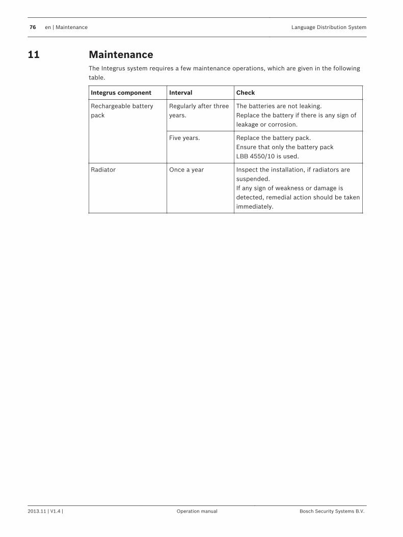
MaintenanceThe Integrus system requires a few maintenance operations, which are given in the followingtable.
Integrus component Interval Check
Rechargeable batterypack
Regularly after threeyears.
The batteries are not leaking.Replace the battery if there is any sign ofleakage or corrosion.
Five years. Replace the battery pack.Ensure that only the battery packLBB 4550/10 is used.
Radiator Once a year Inspect the installation, if radiators aresuspended.If any sign of weakness or damage isdetected, remedial action should be takenimmediately.
11
76 en | Maintenance Language Distribution System
2013.11 | V1.4 | Operation manual Bosch Security Systems B.V.
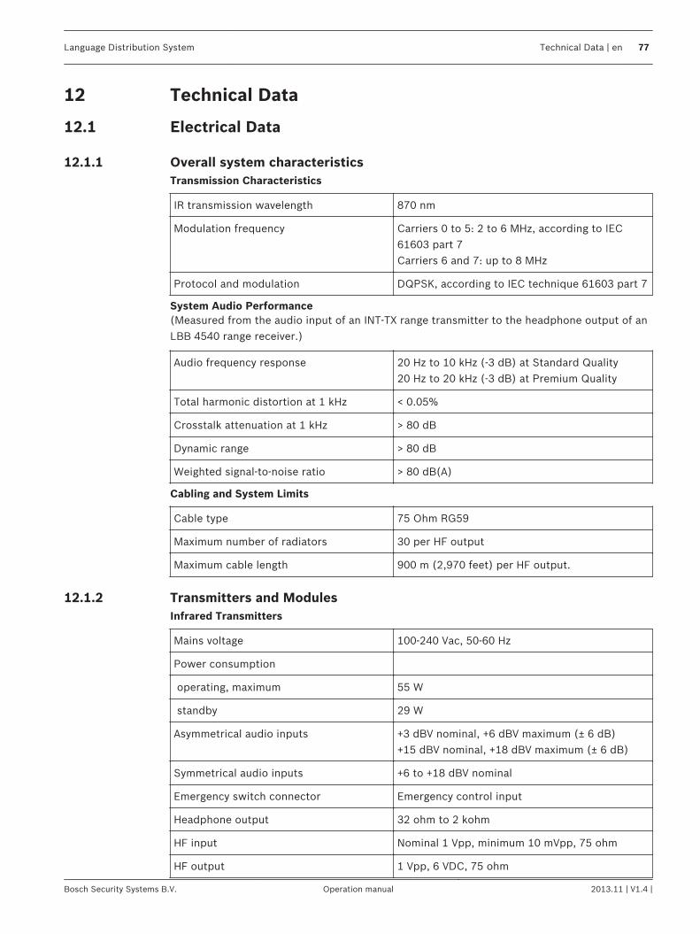
Technical Data
Electrical Data
Overall system characteristicsTransmission Characteristics
IR transmission wavelength 870 nm
Modulation frequency Carriers 0 to 5: 2 to 6 MHz, according to IEC61603 part 7Carriers 6 and 7: up to 8 MHz
Protocol and modulation DQPSK, according to IEC technique 61603 part 7
System Audio Performance(Measured from the audio input of an INT‑TX range transmitter to the headphone output of anLBB 4540 range receiver.)
Audio frequency response 20 Hz to 10 kHz (-3 dB) at Standard Quality20 Hz to 20 kHz (-3 dB) at Premium Quality
Total harmonic distortion at 1 kHz < 0.05%
Crosstalk attenuation at 1 kHz > 80 dB
Dynamic range > 80 dB
Weighted signal-to-noise ratio > 80 dB(A)
Cabling and System Limits
Cable type 75 Ohm RG59
Maximum number of radiators 30 per HF output
Maximum cable length 900 m (2,970 feet) per HF output.
Transmitters and ModulesInfrared Transmitters
Mains voltage 100-240 Vac, 50-60 Hz
Power consumption
operating, maximum 55 W
standby 29 W
Asymmetrical audio inputs +3 dBV nominal, +6 dBV maximum (± 6 dB)+15 dBV nominal, +18 dBV maximum (± 6 dB)
Symmetrical audio inputs +6 to +18 dBV nominal
Emergency switch connector Emergency control input
Headphone output 32 ohm to 2 kohm
HF input Nominal 1 Vpp, minimum 10 mVpp, 75 ohm
HF output 1 Vpp, 6 VDC, 75 ohm
12
12.1
12.1.1
12.1.2
Language Distribution System Technical Data | en 77
Bosch Security Systems B.V. Operation manual 2013.11 | V1.4 |
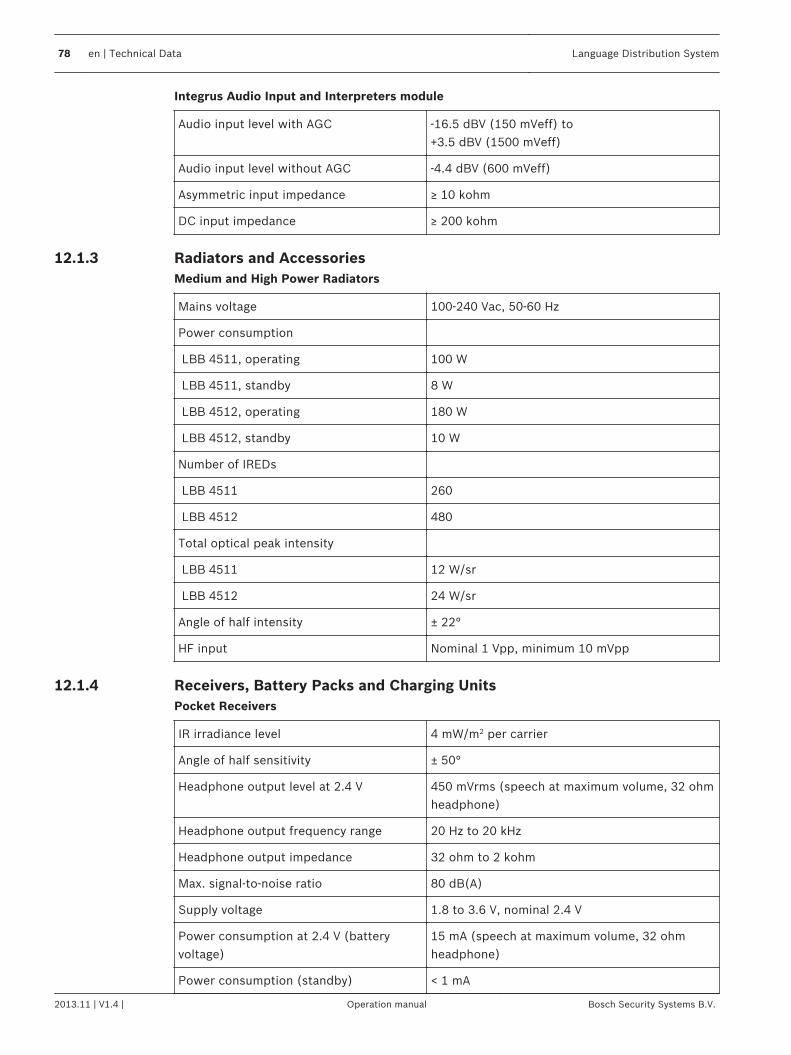
Integrus Audio Input and Interpreters module
Audio input level with AGC -16.5 dBV (150 mVeff) to +3.5 dBV (1500 mVeff)
Audio input level without AGC -4.4 dBV (600 mVeff)
Asymmetric input impedance ≥ 10 kohm
DC input impedance ≥ 200 kohm
Radiators and AccessoriesMedium and High Power Radiators
Mains voltage 100-240 Vac, 50-60 Hz
Power consumption
LBB 4511, operating 100 W
LBB 4511, standby 8 W
LBB 4512, operating 180 W
LBB 4512, standby 10 W
Number of IREDs
LBB 4511 260
LBB 4512 480
Total optical peak intensity
LBB 4511 12 W/sr
LBB 4512 24 W/sr
Angle of half intensity ± 22°
HF input Nominal 1 Vpp, minimum 10 mVpp
Receivers, Battery Packs and Charging UnitsPocket Receivers
IR irradiance level 4 mW/m2 per carrier
Angle of half sensitivity ± 50°
Headphone output level at 2.4 V 450 mVrms (speech at maximum volume, 32 ohmheadphone)
Headphone output frequency range 20 Hz to 20 kHz
Headphone output impedance 32 ohm to 2 kohm
Max. signal-to-noise ratio 80 dB(A)
Supply voltage 1.8 to 3.6 V, nominal 2.4 V
Power consumption at 2.4 V (batteryvoltage)
15 mA (speech at maximum volume, 32 ohmheadphone)
Power consumption (standby) < 1 mA
12.1.3
12.1.4
78 en | Technical Data Language Distribution System
2013.11 | V1.4 | Operation manual Bosch Security Systems B.V.
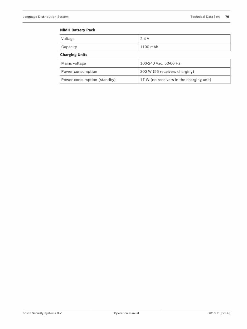
NiMH Battery Pack
Voltage 2.4 V
Capacity 1100 mAh
Charging Units
Mains voltage 100-240 Vac, 50-60 Hz
Power consumption 300 W (56 receivers charging)
Power consumption (standby) 17 W (no receivers in the charging unit)
Language Distribution System Technical Data | en 79
Bosch Security Systems B.V. Operation manual 2013.11 | V1.4 |
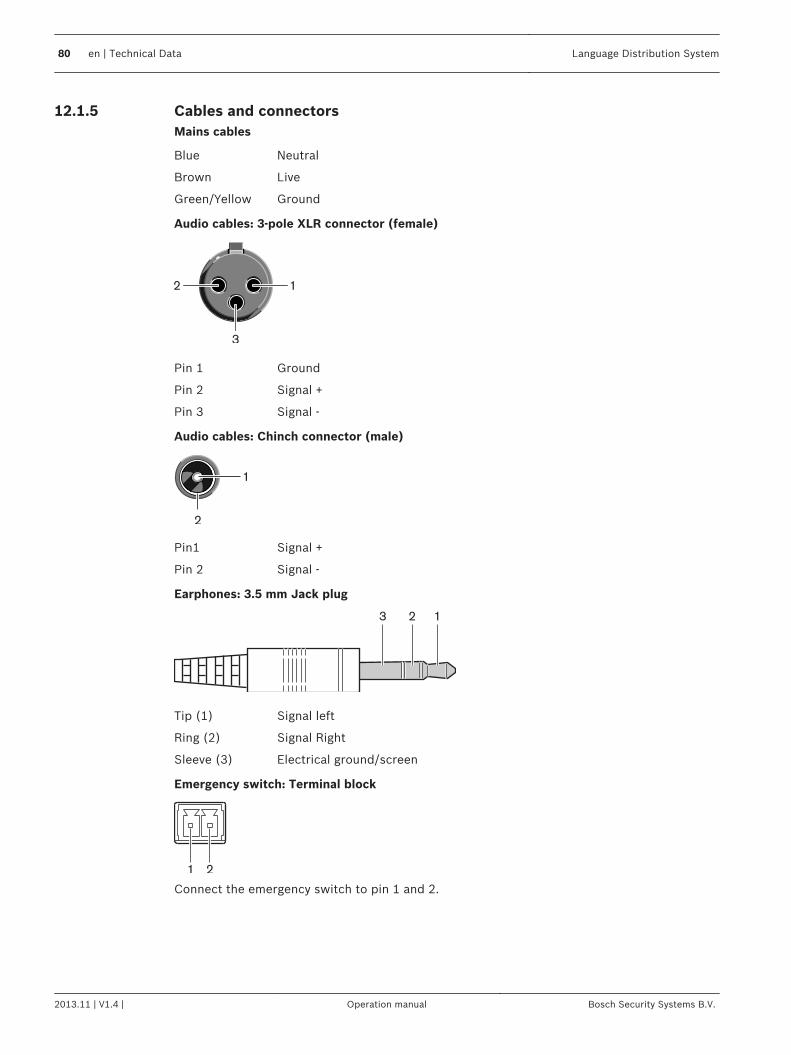
Cables and connectorsMains cables
Blue Neutral
Brown Live
Green/Yellow Ground
Audio cables: 3-pole XLR connector (female)
Pin 1 Ground
Pin 2 Signal +
Pin 3 Signal -
Audio cables: Chinch connector (male)
Pin1 Signal +
Pin 2 Signal -
Earphones: 3.5 mm Jack plug
Tip (1) Signal left
Ring (2) Signal Right
Sleeve (3) Electrical ground/screen
Emergency switch: Terminal block
Connect the emergency switch to pin 1 and 2.
12.1.5
80 en | Technical Data Language Distribution System
2013.11 | V1.4 | Operation manual Bosch Security Systems B.V.
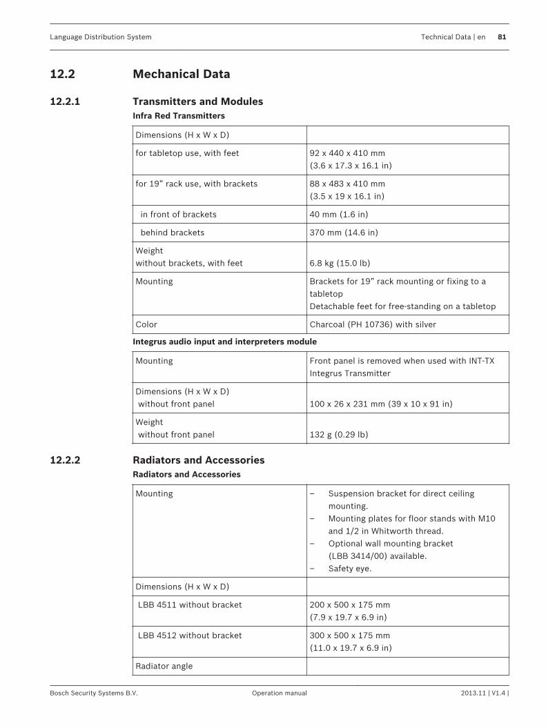
Mechanical Data
Transmitters and ModulesInfra Red Transmitters
Dimensions (H x W x D)
for tabletop use, with feet 92 x 440 x 410 mm(3.6 x 17.3 x 16.1 in)
for 19” rack use, with brackets 88 x 483 x 410 mm(3.5 x 19 x 16.1 in)
in front of brackets 40 mm (1.6 in)
behind brackets 370 mm (14.6 in)
Weightwithout brackets, with feet 6.8 kg (15.0 lb)
Mounting Brackets for 19” rack mounting or fixing to atabletopDetachable feet for free-standing on a tabletop
Color Charcoal (PH 10736) with silver
Integrus audio input and interpreters module
Mounting Front panel is removed when used with INT‑TXIntegrus Transmitter
Dimensions (H x W x D) without front panel 100 x 26 x 231 mm (39 x 10 x 91 in)
Weight without front panel 132 g (0.29 lb)
Radiators and AccessoriesRadiators and Accessories
Mounting – Suspension bracket for direct ceilingmounting.
– Mounting plates for floor stands with M10and 1/2 in Whitworth thread.
– Optional wall mounting bracket(LBB 3414/00) available.
– Safety eye.
Dimensions (H x W x D)
LBB 4511 without bracket 200 x 500 x 175 mm(7.9 x 19.7 x 6.9 in)
LBB 4512 without bracket 300 x 500 x 175 mm(11.0 x 19.7 x 6.9 in)
Radiator angle
12.2
12.2.1
12.2.2
Language Distribution System Technical Data | en 81
Bosch Security Systems B.V. Operation manual 2013.11 | V1.4 |
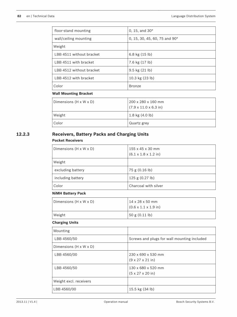
floor-stand mounting 0, 15, and 30°
wall/ceiling mounting 0, 15, 30, 45, 60, 75 and 90°
Weight
LBB 4511 without bracket 6.8 kg (15 lb)
LBB 4511 with bracket 7.6 kg (17 lb)
LBB 4512 without bracket 9.5 kg (21 lb)
LBB 4512 with bracket 10.3 kg (23 lb)
Color Bronze
Wall Mounting Bracket
Dimensions (H x W x D) 200 x 280 x 160 mm(7.9 x 11.0 x 6.3 in)
Weight 1.8 kg (4.0 lb)
Color Quartz grey
Receivers, Battery Packs and Charging UnitsPocket Receivers
Dimensions (H x W x D) 155 x 45 x 30 mm(6.1 x 1.8 x 1.2 in)
Weight
excluding battery 75 g (0.16 lb)
including battery 125 g (0.27 lb)
Color Charcoal with silver
NiMH Battery Pack
Dimensions (H x W x D) 14 x 28 x 50 mm(0.6 x 1.1 x 1.9 in)
Weight 50 g (0.11 lb)
Charging Units
Mounting
LBB 4560/50 Screws and plugs for wall mounting included
Dimensions (H x W x D)
LBB 4560/00 230 x 690 x 530 mm(9 x 27 x 21 in)
LBB 4560/50 130 x 680 x 520 mm(5 x 27 x 20 in)
Weight excl. receivers
LBB 4560/00 15.5 kg (34 lb)
12.2.3
82 en | Technical Data Language Distribution System
2013.11 | V1.4 | Operation manual Bosch Security Systems B.V.
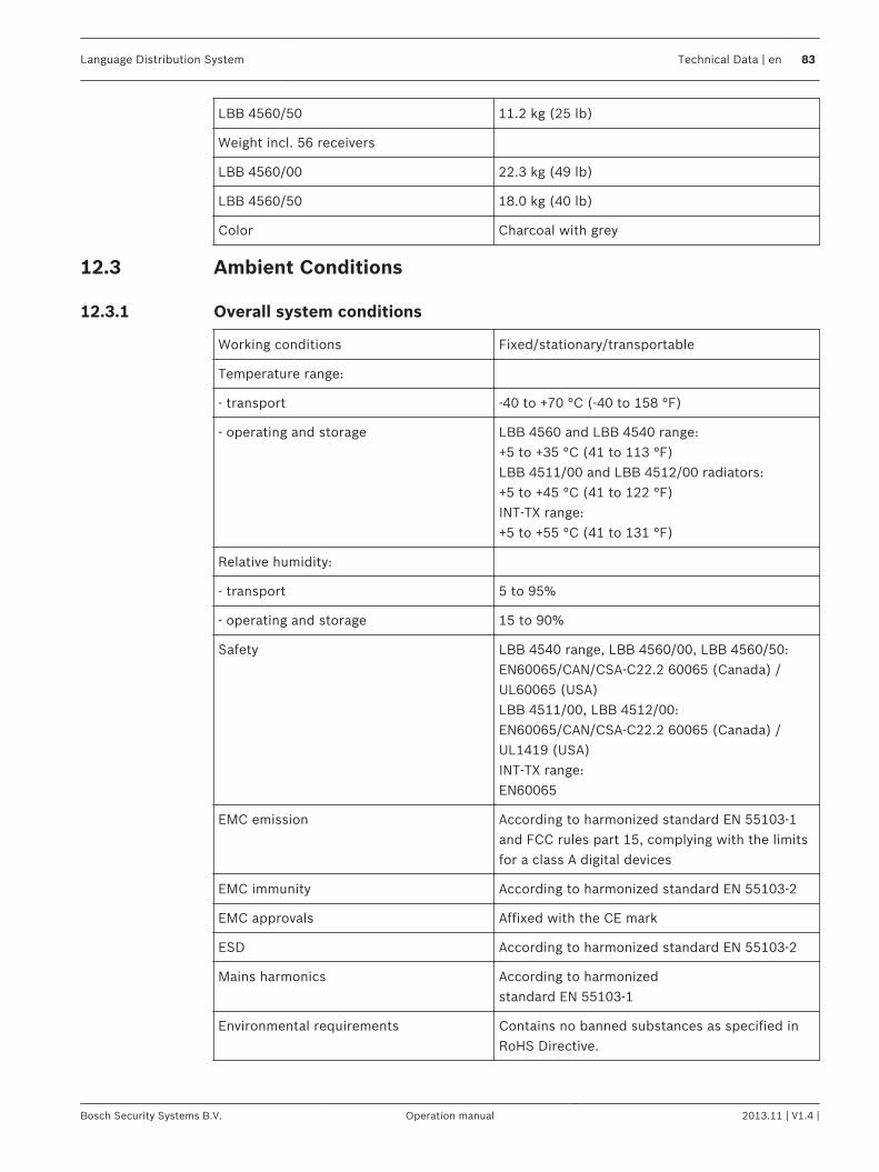
LBB 4560/50 11.2 kg (25 lb)
Weight incl. 56 receivers
LBB 4560/00 22.3 kg (49 lb)
LBB 4560/50 18.0 kg (40 lb)
Color Charcoal with grey
Ambient Conditions
Overall system conditions
Working conditions Fixed/stationary/transportable
Temperature range:
- transport -40 to +70 °C (-40 to 158 °F)
- operating and storage LBB 4560 and LBB 4540 range:+5 to +35 °C (41 to 113 °F)LBB 4511/00 and LBB 4512/00 radiators:+5 to +45 °C (41 to 122 °F)INT‑TX range:+5 to +55 °C (41 to 131 °F)
Relative humidity:
- transport 5 to 95%
- operating and storage 15 to 90%
Safety LBB 4540 range, LBB 4560/00, LBB 4560/50:EN60065/CAN/CSA-C22.2 60065 (Canada) /UL60065 (USA)LBB 4511/00, LBB 4512/00:EN60065/CAN/CSA-C22.2 60065 (Canada) /UL1419 (USA)INT‑TX range:EN60065
EMC emission According to harmonized standard EN 55103‑1and FCC rules part 15, complying with the limitsfor a class A digital devices
EMC immunity According to harmonized standard EN 55103‑2
EMC approvals Affixed with the CE mark
ESD According to harmonized standard EN 55103‑2
Mains harmonics According to harmonizedstandard EN 55103‑1
Environmental requirements Contains no banned substances as specified inRoHS Directive.
12.3
12.3.1
Language Distribution System Technical Data | en 83
Bosch Security Systems B.V. Operation manual 2013.11 | V1.4 |
Rules and Standards
Overall system conformance– Conforms to IEC 60914, the international standard for conference systems– Conforms to IEC 61603 part 7, the international standard for digital infrared transmission
of audio signals for conference and similar applications
12.4
12.4.1
84 en | Technical Data Language Distribution System
2013.11 | V1.4 | Operation manual Bosch Security Systems B.V.
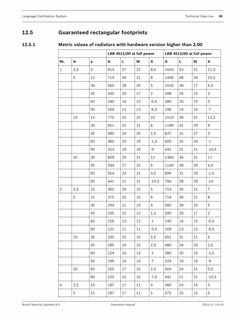
Guaranteed rectangular footprints
Metric values of radiators with hardware version higher than 2.00
LBB 4511/00 at full power LBB 4512/00 at full power
Nr. H a A L W X A L W X
1 2,5 0 814 37 22 8,5 1643 53 31 11,5
5 15 714 34 21 8 1440 48 30 10,5
30 560 28 20 5 1026 38 27 6,5
45 340 20 17 2 598 26 23 3
60 240 16 15 -0,5 380 20 19 0
90 169 13 13 -6,5 196 14 14 -7
10 15 770 35 22 10 1519 49 31 12,5
30 651 31 21 6 1189 41 29 8
45 480 24 20 2,5 837 31 27 3
60 380 20 19 -1,5 600 25 24 -1
90 324 18 18 -9 441 21 21 -10,5
20 30 609 29 21 12 1364 44 31 11
45 594 27 22 6 1140 38 30 4,5
60 504 24 21 0,5 899 31 29 -1,5
90 441 21 21 -10,5 784 28 28 -14
2 2,5 15 360 24 15 5 714 34 21 7
5 15 375 25 15 6 714 34 21 8
30 294 21 14 4 560 28 20 5
45 195 15 12 1,5 340 20 17 2
60 156 13 12 -1 240 16 15 -0,5
90 121 11 11 -5,5 169 13 13 -6,5
10 30 330 22 15 5,5 651 31 21 6
45 285 19 15 2,5 480 24 20 2,5
60 224 16 14 -1 380 20 19 -1,5
90 196 14 14 -7 324 18 18 -9
20 60 255 17 15 2,5 504 24 21 0,5
90 225 15 15 -7,5 441 21 21 -10,5
4 2,5 15 187 17 11 4 360 24 15 5
5 15 187 17 11 5 375 25 15 6
12.5
12.5.1
Language Distribution System Technical Data | en 85
Bosch Security Systems B.V. Operation manual 2013.11 | V1.4 |
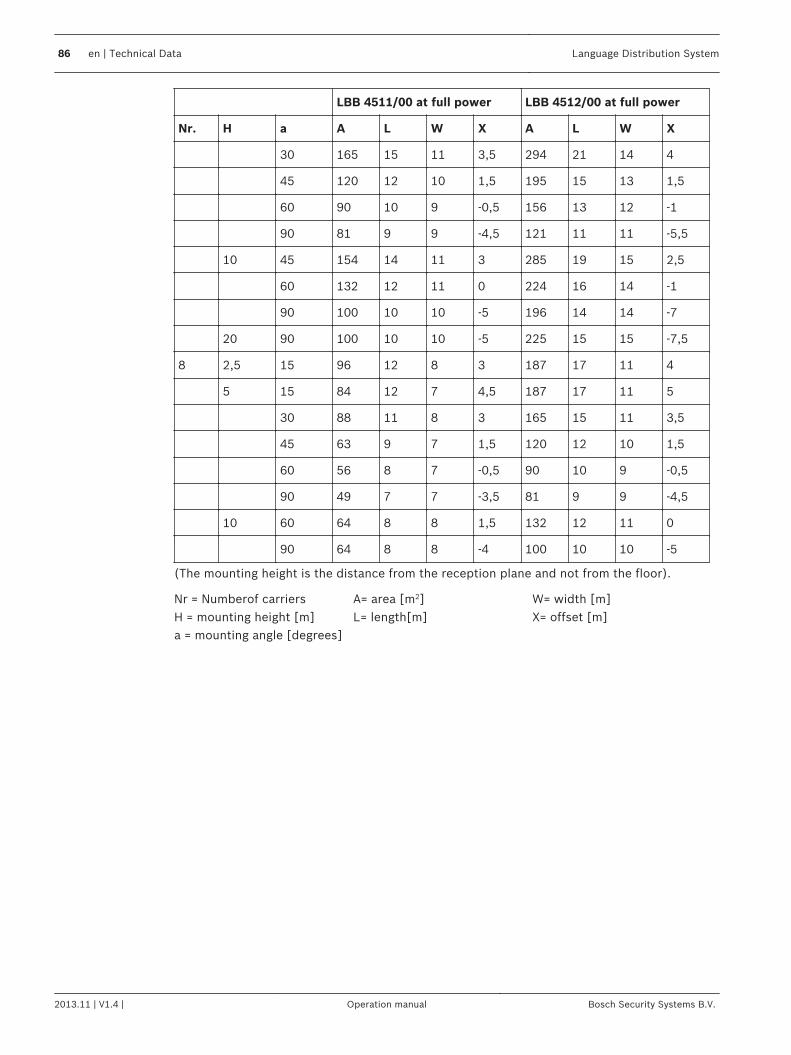
LBB 4511/00 at full power LBB 4512/00 at full power
Nr. H a A L W X A L W X
30 165 15 11 3,5 294 21 14 4
45 120 12 10 1,5 195 15 13 1,5
60 90 10 9 -0,5 156 13 12 -1
90 81 9 9 -4,5 121 11 11 -5,5
10 45 154 14 11 3 285 19 15 2,5
60 132 12 11 0 224 16 14 -1
90 100 10 10 -5 196 14 14 -7
20 90 100 10 10 -5 225 15 15 -7,5
8 2,5 15 96 12 8 3 187 17 11 4
5 15 84 12 7 4,5 187 17 11 5
30 88 11 8 3 165 15 11 3,5
45 63 9 7 1,5 120 12 10 1,5
60 56 8 7 -0,5 90 10 9 -0,5
90 49 7 7 -3,5 81 9 9 -4,5
10 60 64 8 8 1,5 132 12 11 0
90 64 8 8 -4 100 10 10 -5
(The mounting height is the distance from the reception plane and not from the floor).
Nr = Numberof carriersH = mounting height [m]a = mounting angle [degrees]
A= area [m2]L= length[m]
W= width [m]X= offset [m]
86 en | Technical Data Language Distribution System
2013.11 | V1.4 | Operation manual Bosch Security Systems B.V.
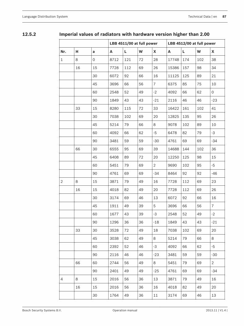
Imperial values of radiators with hardware version higher than 2.00
LBB 4511/00 at full power LBB 4512/00 at full power
Nr. H a A L W X A L W X
1 8 0 8712 121 72 28 17748 174 102 38
16 15 7728 112 69 26 15386 157 98 34
30 6072 92 66 16 11125 125 89 21
45 3696 66 56 7 6375 85 75 10
60 2548 52 49 -2 4092 66 62 0
90 1849 43 43 -21 2116 46 46 -23
33 15 8280 115 72 33 16422 161 102 41
30 7038 102 69 20 12825 135 95 26
45 5214 79 66 8 9078 102 89 10
60 4092 66 62 -5 6478 82 79 -3
90 3481 59 59 -30 4761 69 69 -34
66 30 6555 95 69 39 14688 144 102 36
45 6408 89 72 20 12250 125 98 15
60 5451 79 69 2 9690 102 95 -5
90 4761 69 69 -34 8464 92 92 -46
2 8 15 3871 79 49 16 7728 112 69 23
16 15 4018 82 49 20 7728 112 69 26
30 3174 69 46 13 6072 92 66 16
45 1911 49 39 5 3696 66 56 7
60 1677 43 39 -3 2548 52 49 -2
90 1296 36 36 -18 1849 43 43 -21
33 30 3528 72 49 18 7038 102 69 20
45 3038 62 49 8 5214 79 66 8
60 2392 52 46 -3 4092 66 62 -5
90 2116 46 46 -23 3481 59 59 -30
66 60 2744 56 49 8 5451 79 69 2
90 2401 49 49 -25 4761 69 69 -34
4 8 15 2016 56 36 13 3871 79 49 16
16 15 2016 56 36 16 4018 82 49 20
30 1764 49 36 11 3174 69 46 13
12.5.2
Language Distribution System Technical Data | en 87
Bosch Security Systems B.V. Operation manual 2013.11 | V1.4 |

LBB 4511/00 at full power LBB 4512/00 at full power
Nr. H a A L W X A L W X
45 1287 39 33 5 2107 49 43 5
60 990 33 30 -2 1677 43 39 -3
90 900 30 30 -15 1296 36 36 -18
33 45 1656 46 36 10 3038 62 49 8
60 1404 39 36 0 2392 52 46 -3
90 1089 33 33 -16 2116 46 46 -23
66 90 1089 33 33 -16 2401 49 49 -25
8 8 15 1014 39 26 10 2016 56 36 13
16 15 897 39 23 15 2016 56 36 16
30 936 36 26 10 1764 49 36 11
45 690 30 23 5 1287 39 33 5
60 598 26 23 -2 990 33 30 -2
90 529 23 23 -11 900 30 30 -15
33 60 676 26 26 5 1404 39 36 0
90 676 26 26 -13 1089 33 33 -16
(The mounting height is the distance from the reception plane and not from the floor).
Nr = Numberof carriersH = mounting height [ft]a = mounting angle [degrees]
A= area [ft2]L= length[ft]
W= width [ft]X= offset [ft]
88 en | Technical Data Language Distribution System
2013.11 | V1.4 | Operation manual Bosch Security Systems B.V.
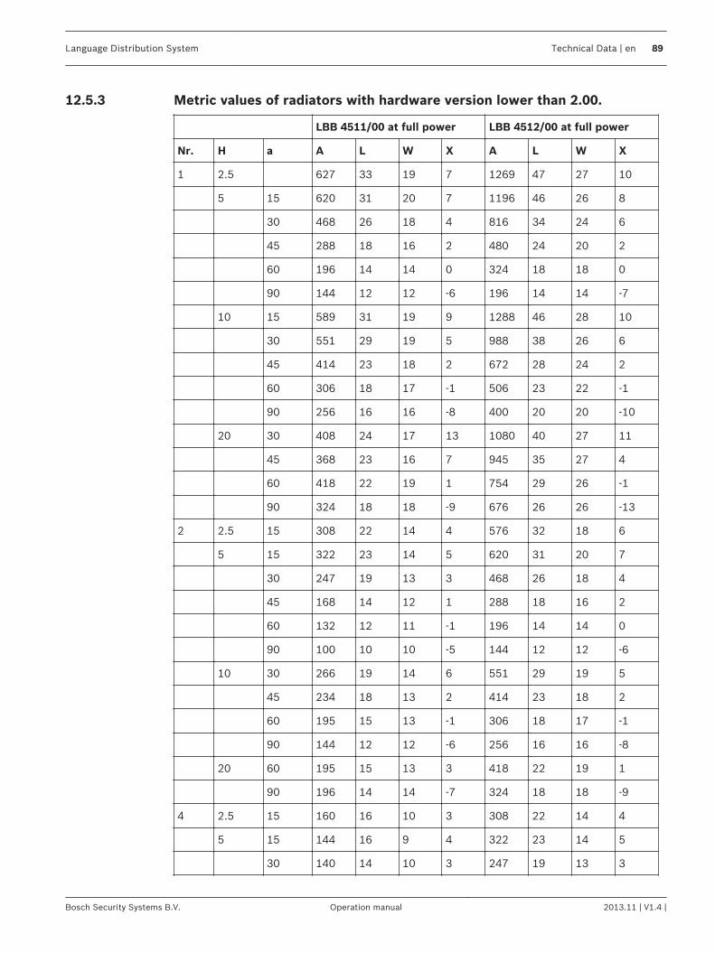
Metric values of radiators with hardware version lower than 2.00.
LBB 4511/00 at full power LBB 4512/00 at full power
Nr. H a A L W X A L W X
1 2.5 627 33 19 7 1269 47 27 10
5 15 620 31 20 7 1196 46 26 8
30 468 26 18 4 816 34 24 6
45 288 18 16 2 480 24 20 2
60 196 14 14 0 324 18 18 0
90 144 12 12 -6 196 14 14 -7
10 15 589 31 19 9 1288 46 28 10
30 551 29 19 5 988 38 26 6
45 414 23 18 2 672 28 24 2
60 306 18 17 -1 506 23 22 -1
90 256 16 16 -8 400 20 20 -10
20 30 408 24 17 13 1080 40 27 11
45 368 23 16 7 945 35 27 4
60 418 22 19 1 754 29 26 -1
90 324 18 18 -9 676 26 26 -13
2 2.5 15 308 22 14 4 576 32 18 6
5 15 322 23 14 5 620 31 20 7
30 247 19 13 3 468 26 18 4
45 168 14 12 1 288 18 16 2
60 132 12 11 -1 196 14 14 0
90 100 10 10 -5 144 12 12 -6
10 30 266 19 14 6 551 29 19 5
45 234 18 13 2 414 23 18 2
60 195 15 13 -1 306 18 17 -1
90 144 12 12 -6 256 16 16 -8
20 60 195 15 13 3 418 22 19 1
90 196 14 14 -7 324 18 18 -9
4 2.5 15 160 16 10 3 308 22 14 4
5 15 144 16 9 4 322 23 14 5
30 140 14 10 3 247 19 13 3
12.5.3
Language Distribution System Technical Data | en 89
Bosch Security Systems B.V. Operation manual 2013.11 | V1.4 |
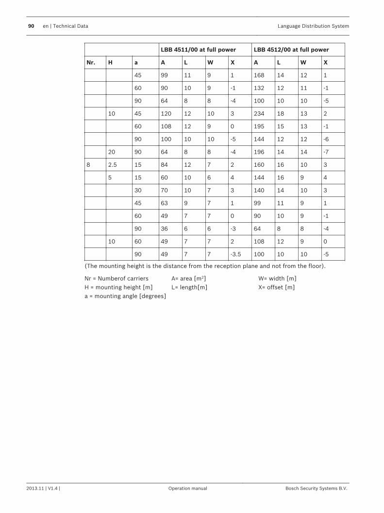
LBB 4511/00 at full power LBB 4512/00 at full power
Nr. H a A L W X A L W X
45 99 11 9 1 168 14 12 1
60 90 10 9 -1 132 12 11 -1
90 64 8 8 -4 100 10 10 -5
10 45 120 12 10 3 234 18 13 2
60 108 12 9 0 195 15 13 -1
90 100 10 10 -5 144 12 12 -6
20 90 64 8 8 -4 196 14 14 -7
8 2.5 15 84 12 7 2 160 16 10 3
5 15 60 10 6 4 144 16 9 4
30 70 10 7 3 140 14 10 3
45 63 9 7 1 99 11 9 1
60 49 7 7 0 90 10 9 -1
90 36 6 6 -3 64 8 8 -4
10 60 49 7 7 2 108 12 9 0
90 49 7 7 -3.5 100 10 10 -5
(The mounting height is the distance from the reception plane and not from the floor).
Nr = Numberof carriersH = mounting height [m]a = mounting angle [degrees]
A= area [m2]L= length[m]
W= width [m]X= offset [m]
90 en | Technical Data Language Distribution System
2013.11 | V1.4 | Operation manual Bosch Security Systems B.V.
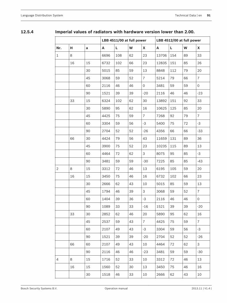
Imperial values of radiators with hardware version lower than 2.00.
LBB 4511/00 at full power LBB 4512/00 at full power
Nr. H a A L W X A L W X
1 8 6696 108 62 23 13706 154 89 33
16 15 6732 102 66 23 12835 151 85 26
30 5015 85 59 13 8848 112 79 20
45 3068 59 52 7 5214 79 66 7
60 2116 46 46 0 3481 59 59 0
90 1521 39 39 -20 2116 46 46 -23
33 15 6324 102 62 30 13892 151 92 33
30 5890 95 62 16 10625 125 85 20
45 4425 75 59 7 7268 92 79 7
60 3304 59 56 -3 5400 75 72 -3
90 2704 52 52 -26 4356 66 66 -33
66 30 4424 79 56 43 11659 131 89 36
45 3900 75 52 23 10235 115 89 13
60 4464 72 62 3 8075 95 85 -3
90 3481 59 59 -30 7225 85 85 -43
2 8 15 3312 72 46 13 6195 105 59 20
16 15 3450 75 46 16 6732 102 66 23
30 2666 62 43 10 5015 85 59 13
45 1794 46 39 3 3068 59 52 7
60 1404 39 36 -3 2116 46 46 0
90 1089 33 33 -16 1521 39 39 -20
33 30 2852 62 46 20 5890 95 62 16
45 2537 59 43 7 4425 75 59 7
60 2107 49 43 -3 3304 59 56 -3
90 1521 39 39 -20 2704 52 52 -26
66 60 2107 49 43 10 4464 72 62 3
90 2116 46 46 -23 3481 59 59 -30
4 8 15 1716 52 33 10 3312 72 46 13
16 15 1560 52 30 13 3450 75 46 16
30 1518 46 33 10 2666 62 43 10
12.5.4
Language Distribution System Technical Data | en 91
Bosch Security Systems B.V. Operation manual 2013.11 | V1.4 |
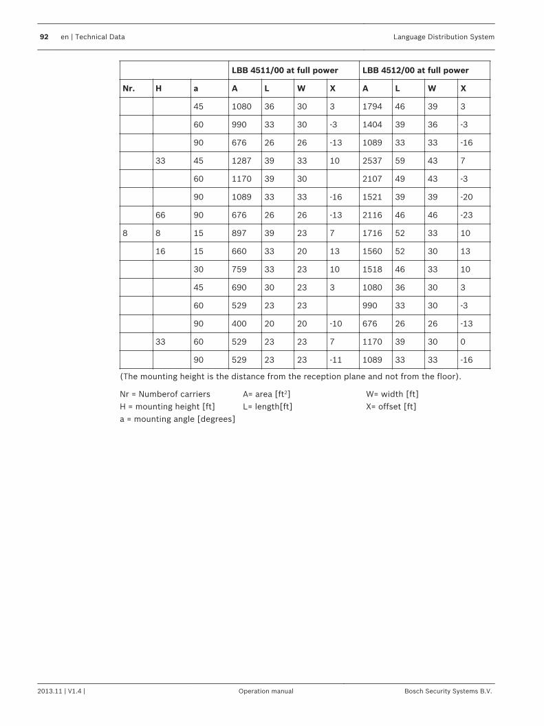
LBB 4511/00 at full power LBB 4512/00 at full power
Nr. H a A L W X A L W X
45 1080 36 30 3 1794 46 39 3
60 990 33 30 -3 1404 39 36 -3
90 676 26 26 -13 1089 33 33 -16
33 45 1287 39 33 10 2537 59 43 7
60 1170 39 30 2107 49 43 -3
90 1089 33 33 -16 1521 39 39 -20
66 90 676 26 26 -13 2116 46 46 -23
8 8 15 897 39 23 7 1716 52 33 10
16 15 660 33 20 13 1560 52 30 13
30 759 33 23 10 1518 46 33 10
45 690 30 23 3 1080 36 30 3
60 529 23 23 990 33 30 -3
90 400 20 20 -10 676 26 26 -13
33 60 529 23 23 7 1170 39 30 0
90 529 23 23 -11 1089 33 33 -16
(The mounting height is the distance from the reception plane and not from the floor).
Nr = Numberof carriersH = mounting height [ft]a = mounting angle [degrees]
A= area [ft2]L= length[ft]
W= width [ft]X= offset [ft]
92 en | Technical Data Language Distribution System
2013.11 | V1.4 | Operation manual Bosch Security Systems B.V.

Bosch Security Systems B.V.Torenallee 495617 BA EindhovenThe Netherlandswww.boschsecurity.com© Bosch Security Systems B.V., 2014