Embed Size (px)
Citation preview
PlenaVoice Alarm System
en Installation and Operation manual

Table of contents
1 Safety 81.1 Important Safeguards 81.2 Important Notices 8
2 About this manual 92.1 Purpose of this manual 92.2 Intended audience 92.3 Related documentation 92.4 Alerts and notice signs 92.5 Conversion tables 102.6 Nomenclature 112.7 Document history 11
3 System overview 123.1 Voice Alarm System 123.1.1 Application types 123.1.2 Application areas 123.1.3 Plena 123.1.4 Praesideo 123.2 Voice Alarm Controller 133.2.1 Hand-held microphone 133.2.2 Internal power amplifier 133.2.3 Internal message manager 133.2.4 Supervision 133.2.5 Trigger inputs 133.2.6 Remote control 143.2.7 Controls, connectors and indicators 143.3 Voice Alarm Router 183.3.1 Loudspeaker zones 183.3.2 Trigger inputs 183.3.3 External power amplifiers 183.3.4 Remote control 183.3.5 Controls, connectors and indicators 193.4 Call Station 213.4.1 Buttons 213.4.2 Supervision 213.4.3 Keypad 223.4.4 Controls, connectors and indicators 233.5 Call Station Keypad 243.6 Voice Alarm Remote Control 253.7 Voice Alarm Remote Control kit 273.8 Remote Control Extension 283.9 Remote Control Extension kit 293.10 Fireman’s Panel 303.11 End Of Line detection board 323.12 Application examples 323.12.1 Schools 323.12.2 Swimming pool 353.12.3 Shopping mall 37
Plena Table of Contents | en 3
Bosch Security Systems B.V. Installation and Operation manual 2013.07 | V2.0 |
3.12.4 Hotel 403.13 Calls and priorities 423.13.1 Priority 423.13.2 Mergeable messages 423.13.3 Business call 423.13.4 Emergency call 42
4 Installation 434.1 Voice Alarm Controller 434.2 Voice Alarm Router 434.3 Call Station Keypad 444.4 Voice Alarm Remote Control 444.5 Voice Alarm Remote Control Kit 444.6 Remote Control Extension 454.7 Remote Control Extension Kit 454.8 End Of Line detection board 454.8.1 Installation of a single EOL 464.8.2 Installation of a multiple EOL in a daisy-chain 464.9 Dummy load 484.9.1 Set the jumper JP1 on the Dummy load 48
5 Connection 495.1 Voice Alarm Controller 495.1.1 Emergency microphone 495.1.2 Call station 505.1.3 Voice alarm routers 515.1.4 External power amplifier 525.1.5 Remote controls 535.1.6 Loudspeakers 545.1.7 Volume overrides 565.1.8 Line output 585.1.9 Mic/line input with VOX 595.1.10 BGM inputs 605.1.11 Status output contacts 615.1.12 Power 625.1.13 Trigger inputs 645.2 Voice Alarm Router 665.2.1 Voice alarm controller 665.2.2 Loudspeakers 665.2.3 Volume overrides 665.2.4 Trigger inputs 665.2.5 External power amplifiers 675.2.6 Power 685.3 Call Station 695.3.1 Voice alarm controller 695.3.2 Power supply 695.3.3 Keypads 695.4 Voice Alarm Remote Control 705.4.1 Voice alarm controller 705.4.2 Remote control extensions 705.4.3 Status output contacts 70
4 en | Table of Contents Plena
2013.07 | V2.0 | Installation and Operation manual Bosch Security Systems B.V.
5.4.4 Power 715.5 Voice Alarm Remote Control Kit 715.5.1 Rear panel 715.5.2 LEDs 715.5.3 Lamps 725.5.4 Relays 725.6 Remote Control Extension 735.6.1 Remote control 735.6.2 Status output contacts 735.6.3 Power 735.7 Remote Control Extension Kit 735.7.1 Rear panel 735.7.2 LEDs 735.7.3 Lamps 735.7.4 Relays 745.8 Fireman’s Panel 745.8.1 Voice alarm controller 745.8.2 Remote control extensions 745.8.3 Status output contacts 745.8.4 Power 74
6 Configuration 756.1 System settings 756.1.1 Monitor 766.1.2 APR mode 766.1.3 Supervision 766.1.4 1-Channel mode operation 776.1.5 2-Channel mode operation 786.2 Supervision 786.2.1 Processor reset 796.2.2 Network 796.2.3 Power amplifiers 796.2.4 Ground short 796.2.5 Emergency trigger inputs 806.2.6 Mains power 806.2.7 Battery 806.2.8 Message supervision 806.2.9 Emergency microphone 806.2.10 Line supervision 806.3 Voice alarm controller 816.3.1 VOX configuration 816.3.2 VOX 826.3.3 Speech filter 826.3.4 Phantom power 826.3.5 Voice alarm router 826.3.6 Router ID 826.3.7 Termination switch 826.4 Call station 836.4.1 Call station ID 836.4.2 Sensitivity 83
Plena Table of Contents | en 5
Bosch Security Systems B.V. Installation and Operation manual 2013.07 | V2.0 |
6.4.3 Speech filter 846.4.4 Termination 846.5 Remote control 856.5.1 Remote control ID 856.5.2 Monitor 856.5.3 Termination switch 856.6 Remote control extension 866.6.1 Remote control extension ID 866.6.2 Termination switch 86
7 Operation 877.1 Switch on 877.1.1 Voice alarm controller 877.1.2 Voice alarm router 877.1.3 Calibration 877.2 Background music 887.2.1 Select BGM source 887.2.2 Select zones 887.2.3 Adjust volume 897.2.4 Adjust frequencies 897.3 Business calls 897.3.1 Select zones 907.3.2 Make the announcement 907.4 Emergency state 917.4.1 Enter the emergency state 917.4.2 Acknowledge the emergency state 927.4.3 Exit the emergency state 927.4.4 Distribute live speech 927.4.5 Select zones 937.4.6 Make the announcement 947.4.7 Distribute the alert message 947.4.8 Distribute the alarm message 967.5 Fault State 967.5.1 Acknowledge the fault state 967.5.2 Reset the fault state 977.5.3 Fault indicators 98
8 Troubleshooting 1018.1 Introduction 1018.2 Message or chime does not sound 1018.3 No pilot tone detected on EOL board 1018.4 No pilot tone detected on power amplifier 1018.5 No BGM on the router 1018.6 No BGM on controller or router 1018.7 No sound coming from the router 1028.8 Volume override only working for EMG, not for business calls (or similar problems) 1028.9 False Ground Short fault 1028.10 Start/Stop function on Trigger Inputs 1028.11 Processor Reset 1038.12 USB port not connected 1038.13 Data fault during configuration upload 103
6 en | Table of Contents Plena
2013.07 | V2.0 | Installation and Operation manual Bosch Security Systems B.V.
8.14 A click sounds through the loudspeakers at regular intervals 1038.15 Password not working 1038.16 Configuration download fails 1038.17 Can’t retrieve the original wave files with the configuration download 104
9 Maintenance 1059.1 Clean the units 1059.2 Clean air inlets 1059.3 Check the connectors and grounding 105
10 Technical data 10610.1 Electrical 10610.1.1 Voice Alarm Controller 10610.1.2 Voice Alarm Router 10910.1.3 Call Station 11010.2 Physical characteristics 11010.2.1 Voice Alarm Controller 11010.2.2 Voice Alarm Router 11110.2.3 Call Station 11110.2.4 Call Station Keypad 11110.2.5 Voice Alarm Remote Control 11110.2.6 Voice Alarm Remote Control Kit 11110.2.7 Remote Control Extension 11110.2.8 Remote Control Extension Kit 11110.2.9 Fireman’s Panel 11210.2.10 End of line detection board 11210.3 Environmental conditions 11210.3.1 Voice Alarm Controller 11210.3.2 Voice Alarm Router 11210.3.3 Call Station 11210.4 Standards 11310.4.1 Voice Alarm Controller 113
11 Appendices 11411.1 Compliancy checklists 11411.1.1 Emergency Sound Systems 11411.1.2 EN60849: 1998 11611.1.3 EN60849 - When using the Remote Control Kits: 13511.1.4 EN54-16 136
Plena Table of Contents | en 7
Bosch Security Systems B.V. Installation and Operation manual 2013.07 | V2.0 |
Safety
Important SafeguardsPrior to installing or operating products, always read the Important Safety Instructions whichare available as a separate multilingual document: Important Safety Instructions (Safety_ML).These instructions are supplied together with all equipment that can be connected to themains supply.
Important NoticesWhen using routers, keypads or more than one call station, configure the controller using thesupplied software.Use shielded cable (CAT-5) between the routers and the controller. The factory default setting of the Plena Voice Alarm System Controller is as follows:– One channel system.– Supervision off.– Please read the latest release notes for the version of the hardware and software you are
using. With firmware (e.g. 3.01.01), the first digit is a major release, where backwardcompatibility is not guaranteed, second digits are changes in functionality that arebackward compatible, the last digits are for bug fixes without impact on functionality.Lastly, the PC configuration software may have an Rx suffix, that indicates changes to thePC configuration software without changes to firmware.
1
1.1
1.2
8 en | Safety Plena
2013.07 | V2.0 | Installation and Operation manual Bosch Security Systems B.V.
About this manual
Purpose of this manualThe purpose of the Installation and Operation manual is to provide information that is requiredto install, configure and operate a Plena Voice Alarm System.
Intended audienceThe Installation and Operation manual is intended for installers and users of an (extensive)Plena Voice Alarm System.
Related documentationThe following related document is available:– Plena Voice Alarm System Configuration Software Manual.
– Refer to the product related information on www.boschsecurity.com.
Alerts and notice signsFour types of signs can be used in this manual. The type is closely related to the effect thatmay be caused if it is not observed. These signs - from least severe effect to most severeeffect - are:
Notice!
Containing additional information. Usually, not observing a ‘notice’ does not result in damage
to the equipment or personal injuries.
!
Caution!
The equipment or the property can be damaged, or persons can be lightly injured if the alert
is not observed.
!Warning!
The equipment or the property can be seriously damaged, or persons can be severely injured
if the alert is not observed.
Danger!
Not observing the alert can lead to severe injuries or death.
2
2.1
2.2
2.3
2.4
Plena About this manual | en 9
Bosch Security Systems B.V. Installation and Operation manual 2013.07 | V2.0 |
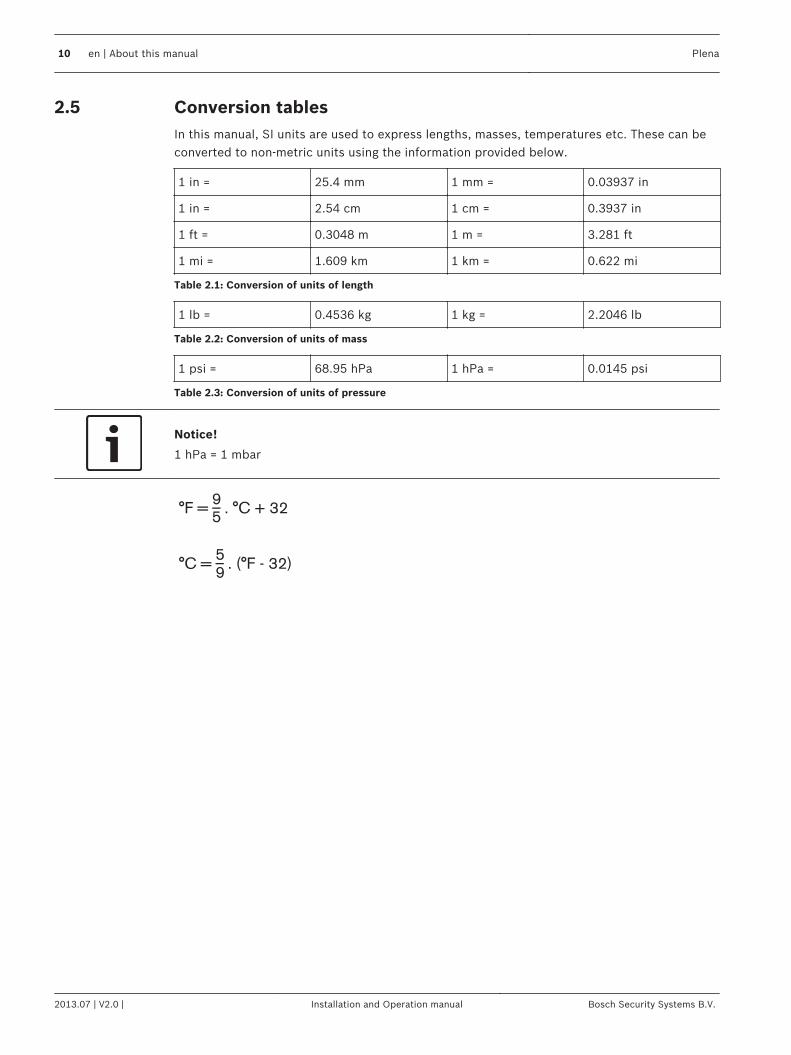
Conversion tablesIn this manual, SI units are used to express lengths, masses, temperatures etc. These can beconverted to non-metric units using the information provided below.
1 in = 25.4 mm 1 mm = 0.03937 in
1 in = 2.54 cm 1 cm = 0.3937 in
1 ft = 0.3048 m 1 m = 3.281 ft
1 mi = 1.609 km 1 km = 0.622 mi
Table 2.1: Conversion of units of length
1 lb = 0.4536 kg 1 kg = 2.2046 lb
Table 2.2: Conversion of units of mass
1 psi = 68.95 hPa 1 hPa = 0.0145 psi
Table 2.3: Conversion of units of pressure
Notice!
1 hPa = 1 mbar
°F = _ . °C + 32
95
°C = _ . (°F - 32)
59
2.5
10 en | About this manual Plena
2013.07 | V2.0 | Installation and Operation manual Bosch Security Systems B.V.
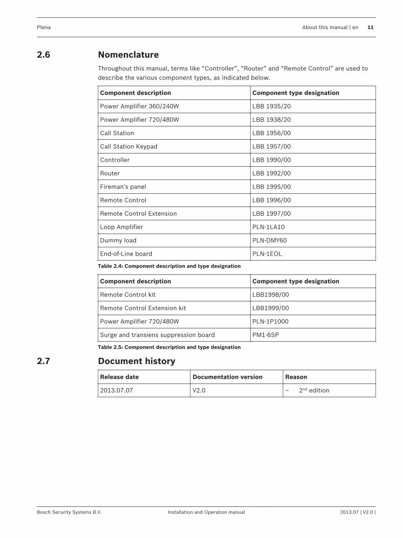
NomenclatureThroughout this manual, terms like “Controller”, “Router” and “Remote Control” are used todescribe the various component types, as indicated below.
Component description Component type designation
Power Amplifier 360/240W LBB 1935/20
Power Amplifier 720/480W LBB 1938/20
Call Station LBB 1956/00
Call Station Keypad LBB 1957/00
Controller LBB 1990/00
Router LBB 1992/00
Fireman's panel LBB 1995/00
Remote Control LBB 1996/00
Remote Control Extension LBB 1997/00
Loop Amplifier PLN-1LA10
Dummy load PLN‑DMY60
End-of-Line board PLN‑1EOL
Table 2.4: Component description and type designation
Component description Component type designation
Remote Control kit LBB1998/00
Remote Control Extension kit LBB1999/00
Power Amplifier 720/480W PLN‑1P1000
Surge and transiens suppression board PM1‑6SP
Table 2.5: Component description and type designation
Document history
Release date Documentation version Reason
2013.07.07 V2.0 – 2nd edition
2.6
2.7
Plena About this manual | en 11
Bosch Security Systems B.V. Installation and Operation manual 2013.07 | V2.0 |
System overview
Voice Alarm SystemThe Plena Voice Alarm System is a public address and voice alarm system in which features forcompliance to evacuation standards such as EN60849, NEN2575, BS5839/8 and EN54-16 areintegrated.
Application typesTypically, the Plena Voice Alarm System is used to create small systems that must comply toevacuation standards, medium-sized systems in which one call channel is enough and largesystems that consist of many small zones.
Application areasThe application areas of the Plena Voice Alarm System include:– Supermarkets, shops– Factories– High-rise buildings– Office buildings– Schools– Recreational facilities– Hotels– Small airports
PlenaThe Plena Voice Alarm System is part of the Plena product range. Plena provides publicaddress solutions for places where people gather to work, worship, trade or simply enjoythemselves. It is a family of system elements that are combined to create public addresssystems tailored for virtually any application. The range includes mixer, pre, system and poweramplifiers, a source unit, digital message manager, feedback suppressor, conventional and PCcall stations, an ‘All-in-One’ system, an audio interface, a timer, a charger, a loop amplifier, aBGM source and a voice alarm system. Each element is designed to complement all othersthanks to matched acoustical, electrical and mechanical specifications.
PraesideoIt is possible to combine the Plena Voice Alarm System with e.g. a Praesideo digital publicaddress and emergency sound system, or a Promatrix or other system. When an audio outputof Praesideo is connected to a VOX audio input of the Plena Voice Alarm System, calls that aremade by the Praesideo system overrule the calls that are made with the Plena Voice AlarmSystem.
3
3.1
3.1.1
3.1.2
3.1.3
3.1.4
12 en | System overview Plena
2013.07 | V2.0 | Installation and Operation manual Bosch Security Systems B.V.
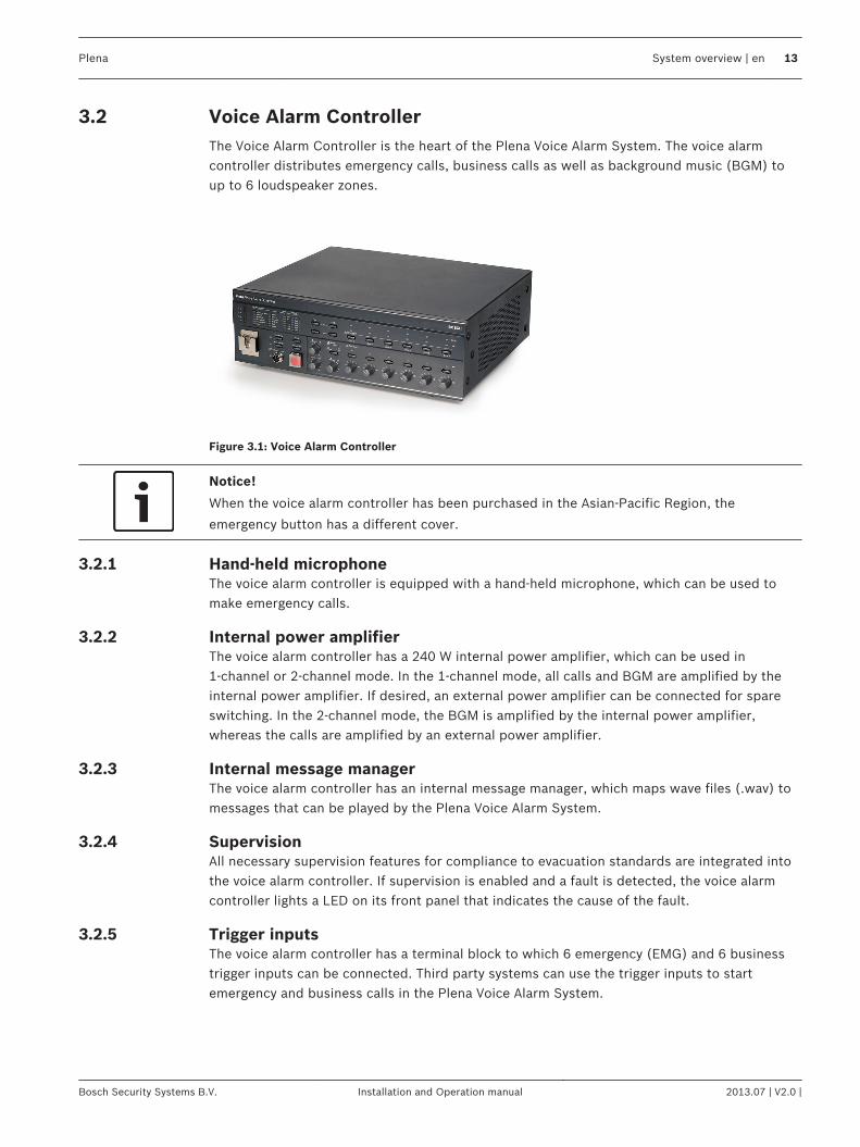
Voice Alarm ControllerThe Voice Alarm Controller is the heart of the Plena Voice Alarm System. The voice alarmcontroller distributes emergency calls, business calls as well as background music (BGM) toup to 6 loudspeaker zones.
Figure 3.1: Voice Alarm Controller
Notice!
When the voice alarm controller has been purchased in the Asian-Pacific Region, the
emergency button has a different cover.
Hand-held microphoneThe voice alarm controller is equipped with a hand-held microphone, which can be used tomake emergency calls.
Internal power amplifierThe voice alarm controller has a 240 W internal power amplifier, which can be used in1‑channel or 2‑channel mode. In the 1‑channel mode, all calls and BGM are amplified by theinternal power amplifier. If desired, an external power amplifier can be connected for spareswitching. In the 2‑channel mode, the BGM is amplified by the internal power amplifier,whereas the calls are amplified by an external power amplifier.
Internal message managerThe voice alarm controller has an internal message manager, which maps wave files (.wav) tomessages that can be played by the Plena Voice Alarm System.
SupervisionAll necessary supervision features for compliance to evacuation standards are integrated intothe voice alarm controller. If supervision is enabled and a fault is detected, the voice alarmcontroller lights a LED on its front panel that indicates the cause of the fault.
Trigger inputsThe voice alarm controller has a terminal block to which 6 emergency (EMG) and 6 businesstrigger inputs can be connected. Third party systems can use the trigger inputs to startemergency and business calls in the Plena Voice Alarm System.
3.2
3.2.1
3.2.2
3.2.3
3.2.4
3.2.5
Plena System overview | en 13
Bosch Security Systems B.V. Installation and Operation manual 2013.07 | V2.0 |
Remote controlWith the Voice Alarm Remote Control, it is possible to control the voice alarm controller fromanother site. The remote control is also available as kit (Voice Alarm Remote Control Kit) forcreating customized solutions. The maximum number of remote controls that can beconnected to the voice alarm controller is 2. A special type of remote control is the Fireman’sPanel.
Controls, connectors and indicators
0- +
- +
0 dB
-6dB
-20dB
Processor reset
Network
Call/EMG
Music/Spare
Ground short
Input
Mains
Battery
Zone1
Zone2
Zone3
Zone4
Zone5
Zone6
Alarm
Zone select
Plena Voice Alarm Controller
Fault Indicators
CD/Tuner Aux
Select Zone select
Indicator test
EMG mic
Alert message
Alarm message
All call
Zone1 Zone2 Zone3 Zone4 Zone5 Zone6
Fault EMG
Ack
Reset
A B
Disabled
Message
EMG mic
RCP
Router
COM
NC NO
10 k 10 k
Trigger input/24V DC out
Business
Emergency
NC
TRG2
Override/Trigger Output
AUX
L
R
PC Digital
Mess ageMonitoring
Speaker
Remote Control Panel
Impedance
Calibration
In
LBB 1 990/00 8900 199 0 0001
Plena Voice Alarm ControllerMax. output power 360WRated output power 240W115-230V~, 50/60Hz
S/N.
Design & QualityThe Netherlands
N6 63
Phantom power
Z1
Z2
Z3
Z4
Z5
Z6
ExtB ooster
In
DC In
100V
0
TRG 1
Int
B ooster
Out
24V
EM G
Fault
C all
External Booster
Out
CD/Tuner
SEL1
SEL0
Firmware
Upgrade
Monitor
APR modeSupervision2ch operationReserved
Off
On
USB
Vox
Speech filter
Mic/Line
Vox
Reserved
Rated input power :760VA
Line fuseT6.3L250V for230V ACT10L250V for115V AC
115V~ 230V~
Apparatus delivered
C onnected for 230V~
Power
Router
W arningThis apparatus must be earthed
100V
0
100V
0
100V
0
100V
0
100V
0
100V
024V
70 V
Z1
Z2
Z3
Z4
Z5
Z6
GND
Reserved
1 2 3 4 5 6
1 2 3 4 5 6
1 2 3 4 5 6
Off
On
Off
On
Call station For ser vice only
GND
24V
DC out
VO X
Switch
VOX Switch1 2 3 4 5 6
NC
COM
NO
NC
COM
NO
NC
COM
NO
100V
0
C all out
100V
0
100V
0
100V
0
100V
0
100V
0
100V
0
Z2
Z3
Z4
Z5
Z6
Z1
A B
NO
24V
DC out
24V
1 Channel 2 Channel
Int Booster
Ext Booster
BGM/ Spare
N.C ./Spare Call
BGM/ C all
Volume Override
10 0V
Ma
de
in C
hin
a1
2
1
2
EMG. Mic
1 2 3 4 5
6712151617
32333435363739
101389
384041424647
18 19 20 22 23 24 25 26 27 28 30 312921
4445 43
1114
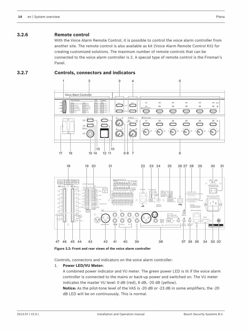
Figure 3.2: Front and rear views of the voice alarm controller
Controls, connectors and indicators on the voice alarm controller:1. Power LED/VU Meter:
A combined power indicator and VU meter. The green power LED is lit if the voice alarmcontroller is connected to the mains or back-up power and switched on. The VU meterindicates the master VU level: 0 dB (red), 6 dB, -20 dB (yellow).Notice: As the pilot-tone level of the VAS is -20 dB or -23 dB in some amplifiers, the -20dB LED will be on continuously. This is normal.
3.2.6
3.2.7
14 en | System overview Plena
2013.07 | V2.0 | Installation and Operation manual Bosch Security Systems B.V.
2. Fault indicators:Twelve yellow system fault LEDs (Processor reset, Network, Call/EMG, Music/Spare,Ground short, Input, Mains, Battery, Message, EMG mic, RCP and Router) and twelveyellow loudspeaker line fault LEDs. Fault indication is only possible if supervision isenabled (see section Fault indicators, page 98). If supervision is disabled, the yellowDisabled LED is lit.
3. Fault state buttons:Two buttons to acknowledge (Ack) and reset (Reset) the fault state (see section FaultState, page 96).
4. Emergency state buttons:Two buttons to acknowledge (Ack) and reset (Reset) the emergency state (see sectionEmergency state, page 91).
5. Emergency call zone selectors:Six buttons to select the zones to which the emergency call must be distributed (seesection Emergency state, page 91). Each button has a green and a red LED. The six redLEDs indicate the zones that are selected for the emergency call. The six green LEDsindicate the zones in which a business call is running.
6. BGM zone selectors:Six buttons to select the zones to which the BGM is distributed (see section Backgroundmusic, page 88). Each button has a green LED and a rotary knob. The six green LEDsindicate the zones to which BGM is distributed. The six rotary knobs are local volumecontrols that can be used to adjust the volume of the BGM in each zone. Each volumecontrol knob has six settings.
7. BGM master volume control:A rotary knob to set the master volume of the BGM (see section Background music, page88).
8. BGM source selector:A button to select the BGM source (CD/Tuner or Aux). The selected source is indicatedwith a green LED (see section Background music, page 88).
9. BGM tone controls:Two rotary knobs to control the high and low frequencies of the BGM (see sectionBackground music, page 88).
10. All call button:A button to select all zones. This button is only available in the emergency state (seesection Emergency state, page 91).
11. Indicator test button: A button to test all LEDs on the front panel of the voice alarm controller, and connectedvoice alarm routers, remote control panels, remote control extensions and fireman’spanels. All LEDs are lit as long as the button is pushed (see section Fault State, page96).
12. Emergency button:A push button to put the system in the emergency state (see sectionEmergency state, page91).
13. Alert message button:A button to select the alert message. This button is only available in the emergency state(see section Emergency state, page 91).
14. Alarm message button:A button to select the default alarm message. This button is only available in theemergency state (see section Emergency state, page 91).
Plena System overview | en 15
Bosch Security Systems B.V. Installation and Operation manual 2013.07 | V2.0 |
15. Microphone socket:A socket to connect the hand-held emergency microphone (see section Emergencymicrophone, page 49).
16. Bracket:A bracket for the hand-held emergency microphone that is supplied with the voice alarmcontroller.
17. Monitoring speaker:Built-in monitoring speaker.
18. Zone outputs:Six zone outputs to connect loudspeakers to the voice alarm controller. Each zone outputconsists of two loudspeaker line outputs (see section Loudspeakers, page 54).
19. Override outputs:Six volume override outputs to override local volume controls in each zone (see sectionVolume overrides, page 56).
20. Status outputs:Three status outputs to send the status of the Plena Voice Alarm System to third partyequipment (see section Status output contacts, page 61).
21. Trigger inputs/24 V DC output:Twelve trigger inputs to receive signals from third party equipment and one 24 V(DC)output (see section Trigger inputs, page 64).
22. Call station sockets:Two RJ45 sockets to connect call stations to the voice alarm controller (see section Callstation, page 50).
23. Service settings:A set of DIP switches to service the voice alarm controller. Do not change the positions ofthe switches.
24. Calibration switch:A switch to calibrate the impedances of the loudspeaker lines for loudspeaker supervision(see section Calibration, page 87).
25. Configuration settings:A set of DIP switches to configure the system (see section System settings, page 75).
26. PC socket:A USB socket to connect the voice alarm controller to a PC.Refer to the Configuration Software Manual for more information about connecting a PCto the voice alarm controller.
27. Emergency microphone volume control:A rotary knob to set the volume of the hand-held emergency microphone.
28. Reserved.29. Reserved:
To connect an OI, or for upgrades (only for authorized use).30. Voltage selector:
A voltage selector to select the local mains voltage (see section Power, page 62).31. Power switch:
A switch to switch the voice alarm controller on and off (see section Power, page 62).32. Ground:
A connection to electrically ground the voice alarm controller.33. Mains power inlet:
A socket to connect the voice alarm controller to the mains power (see section Power,page 62).
16 en | System overview Plena
2013.07 | V2.0 | Installation and Operation manual Bosch Security Systems B.V.
34. Router socket:An RJ45 socket to connect voice alarm routers to the voice alarm controller (see sectionVoice alarm routers, page 51).
35. Remote control panel socket:Two RJ45 sockets to connect remote control panels (Fireman’s panel, Remote Control,Remote Control kit) to the voice alarm controller.
36. Monitoring speaker volume control:A rotary knob to set the volume of the monitoring loudspeaker.
37. Digital message volume control:A rotary knob to set the volume of the digital messages. This volume control does notinfluence the volume of the emergency messages.
38. Mic/line input with VOX functionality:An XLR socket and a 6.3 mm jack with voice-activated (VOX) functionality to connect amicrophone or line input to the voice alarm controller (see section Mic/line input withVOX, page 59). The VOX settings are configured with the DIP switches and the sourceswitch (see section VOX configuration, page 81).
39. PC Call station input:An input to connect a PC call station. For future use.
40. BGM inputs:Two inputs to connect background music sources. Each input consists of two cinchsockets (see section BGM inputs, page 60).
41. Line output:A line output to connect an external recording device to record the audio of the PlenaVoice Alarm System (see section Line output, page 58).
42. External power amplifier (output):An XLR socket to connect an external power amplifier (see section External poweramplifier, page 52). This socket is used in combination with the external power amplifierinput (no. 47).
43. Trigger outputs:Two general purpose trigger outputs. For future use. TR1 is active during impedancecheck.
44. Internal power amplifier output:Three pins that provide the 100 V audio signal of the internal power amplifier of the voicealarm controller. Also includes a 70 V connection.
45. Call output:An output that provides the call audio of the Plena Voice Alarm System.
46. Back-up power inlet:An inlet to connect a back-up power supply to the voice alarm controller (see sectionPower, page 62).
47. External power amplifier (input):An input to connect an external power amplifier (see section External power amplifier,page 52). These pins are used in combination with the external power amplifier output(no. 42).
Plena System overview | en 17
Bosch Security Systems B.V. Installation and Operation manual 2013.07 | V2.0 |
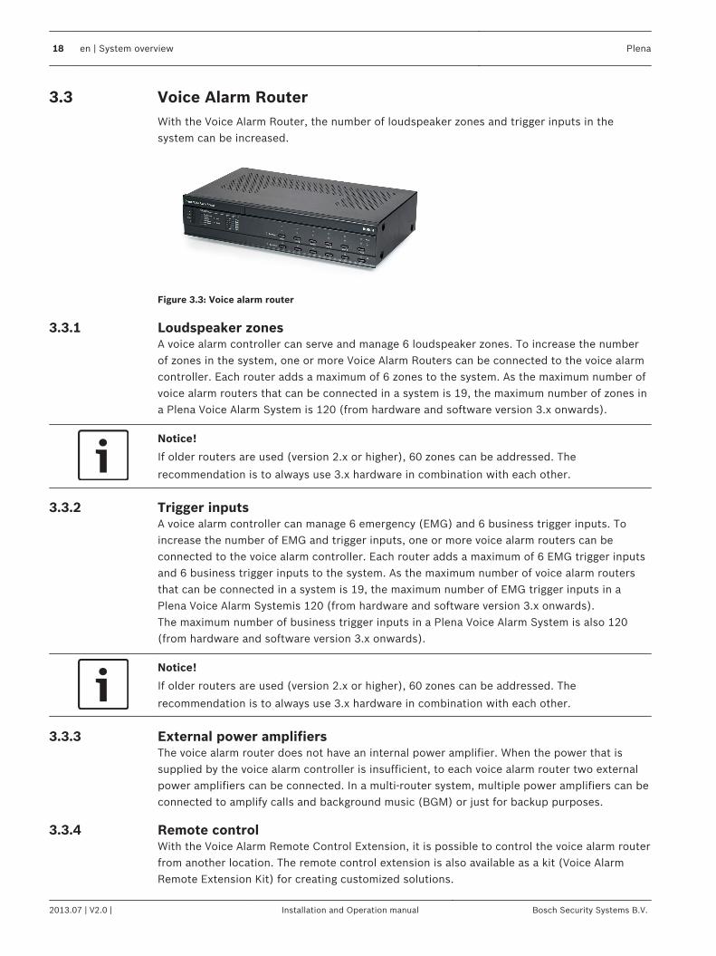
Voice Alarm RouterWith the Voice Alarm Router, the number of loudspeaker zones and trigger inputs in thesystem can be increased.
Figure 3.3: Voice alarm router
Loudspeaker zonesA voice alarm controller can serve and manage 6 loudspeaker zones. To increase the numberof zones in the system, one or more Voice Alarm Routers can be connected to the voice alarmcontroller. Each router adds a maximum of 6 zones to the system. As the maximum number ofvoice alarm routers that can be connected in a system is 19, the maximum number of zones ina Plena Voice Alarm System is 120 (from hardware and software version 3.x onwards).
Notice!
If older routers are used (version 2.x or higher), 60 zones can be addressed. The
recommendation is to always use 3.x hardware in combination with each other.
Trigger inputsA voice alarm controller can manage 6 emergency (EMG) and 6 business trigger inputs. Toincrease the number of EMG and trigger inputs, one or more voice alarm routers can beconnected to the voice alarm controller. Each router adds a maximum of 6 EMG trigger inputsand 6 business trigger inputs to the system. As the maximum number of voice alarm routersthat can be connected in a system is 19, the maximum number of EMG trigger inputs in aPlena Voice Alarm Systemis 120 (from hardware and software version 3.x onwards).The maximum number of business trigger inputs in a Plena Voice Alarm System is also 120(from hardware and software version 3.x onwards).
Notice!
If older routers are used (version 2.x or higher), 60 zones can be addressed. The
recommendation is to always use 3.x hardware in combination with each other.
External power amplifiersThe voice alarm router does not have an internal power amplifier. When the power that issupplied by the voice alarm controller is insufficient, to each voice alarm router two externalpower amplifiers can be connected. In a multi‑router system, multiple power amplifiers can beconnected to amplify calls and background music (BGM) or just for backup purposes.
Remote controlWith the Voice Alarm Remote Control Extension, it is possible to control the voice alarm routerfrom another location. The remote control extension is also available as a kit (Voice AlarmRemote Extension Kit) for creating customized solutions.
3.3
3.3.1
3.3.2
3.3.3
3.3.4
18 en | System overview Plena
2013.07 | V2.0 | Installation and Operation manual Bosch Security Systems B.V.
Controls, connectors and indicators
Plena Voice Alarm Router
0 dB
-6dB
-20dB
B
Processor reset
Network
Call/EMG
Music/Spare
Ground short
Input
Mains
Battery
Zone1
Zone2
Zone3
Zone4
Zone5
Zone6
Alarm
Zone select
A
Fault Indicators
Zone select
Zone1 Zone2 Zone3 Zone4 Zone5 Zone6
10k 10k
Booster 1 in
Override/Trigger Output Trigger Input
Business
Emergency
Firmware upgrade
Firmware Upgrade
LBB 1992/00 8900 199 20001
Plena Voice Alarm Router
115-230V~,50/60Hz
S/N.
Design & QualityThe Netherlands
N663
Termination
100V 0 100V 0 100V 0 100V 0 100V 0 100V 0 100V 70V 0 100V
Z1 Z2 Z3 Z4 Z5 Z6
Booster 1
Out
1...9
ID
Router
Rated input power:100VALine fuse:T1L250V for 230V AC
T2L250V for 115V AC
WarningThis apparatus must be earthde
TRG1 TRG2
1 2 3 4 5 6
COM
NC NO
1 2 3 4 5 6
1 2 3 4 5 6
1 2 3 4 5 6
Z1 Z2 Z3 Z4 Z5
BoosterFailure
GND
Booster 2
Z6
24VDC Out
TRG1 TRG2BoosterFailure
24VDC Out
A
100V 0 100V 0 100V 0 100V 0 100V 0 100V 0 100V 0 +24V-
Booster 2 inZ1 Z2 Z3 Z4 Z5 Z6B DC In
Z1 Z2 Z3 Z4 Z5 Z6
24V
1 Channel 2 Channel
Booster 1
Booster 2
BGM/Spare
N.C./Spare Call
BGM/Call
V.O.R.
V.O.R.
NC NO
24V
In
Out
Power
Apparatus deliveredConnected for 230V~
115V~ 230V~
Call out Mad
ein
Chin
a
Off
On
1
76
2 3
4
5 9 10 118 12
131415161718192024
2122
23
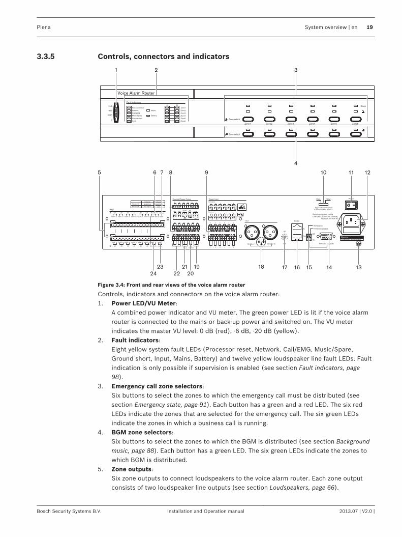
Figure 3.4: Front and rear views of the voice alarm router
Controls, indicators and connectors on the voice alarm router:1. Power LED/VU Meter:
A combined power indicator and VU meter. The green power LED is lit if the voice alarmrouter is connected to the mains or back-up power and switched on. The VU meterindicates the master VU level: 0 dB (red), -6 dB, -20 dB (yellow).
2. Fault indicators:Eight yellow system fault LEDs (Processor reset, Network, Call/EMG, Music/Spare,Ground short, Input, Mains, Battery) and twelve yellow loudspeaker line fault LEDs. Faultindication is only possible if supervision is enabled (see section Fault indicators, page98).
3. Emergency call zone selectors:Six buttons to select the zones to which the emergency call must be distributed (seesection Emergency state, page 91). Each button has a green and a red LED. The six redLEDs indicate the zones that are selected for the emergency call. The six green LEDsindicate the zones in which a business call is running.
4. BGM zone selectors:Six buttons to select the zones to which the BGM is distributed (see section Backgroundmusic, page 88). Each button has a green LED. The six green LEDs indicate the zones towhich BGM is distributed.
5. Zone outputs:Six zone outputs to connect loudspeakers to the voice alarm router. Each zone outputconsists of two loudspeaker line outputs (see section Loudspeakers, page 66).
3.3.5
Plena System overview | en 19
Bosch Security Systems B.V. Installation and Operation manual 2013.07 | V2.0 |
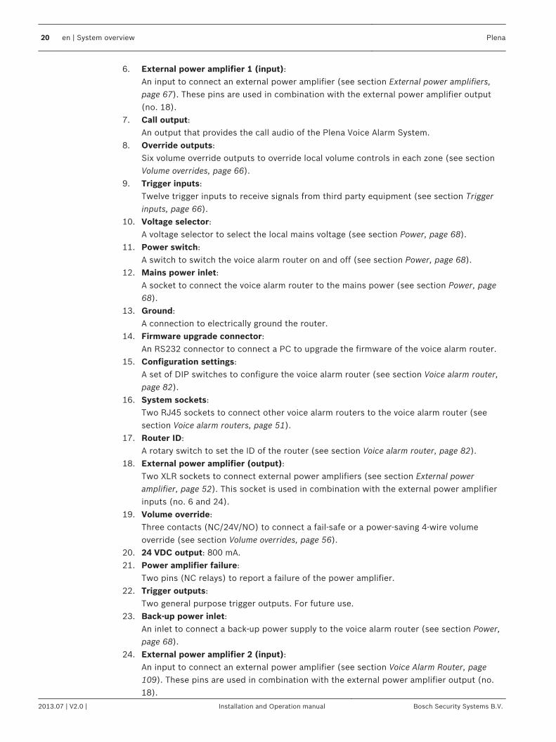
6. External power amplifier 1 (input):An input to connect an external power amplifier (see section External power amplifiers,page 67). These pins are used in combination with the external power amplifier output(no. 18).
7. Call output:An output that provides the call audio of the Plena Voice Alarm System.
8. Override outputs:Six volume override outputs to override local volume controls in each zone (see sectionVolume overrides, page 66).
9. Trigger inputs:Twelve trigger inputs to receive signals from third party equipment (see section Triggerinputs, page 66).
10. Voltage selector:A voltage selector to select the local mains voltage (see section Power, page 68).
11. Power switch:A switch to switch the voice alarm router on and off (see section Power, page 68).
12. Mains power inlet:A socket to connect the voice alarm router to the mains power (see section Power, page68).
13. Ground:A connection to electrically ground the router.
14. Firmware upgrade connector:An RS232 connector to connect a PC to upgrade the firmware of the voice alarm router.
15. Configuration settings:A set of DIP switches to configure the voice alarm router (see section Voice alarm router,page 82).
16. System sockets:Two RJ45 sockets to connect other voice alarm routers to the voice alarm router (seesection Voice alarm routers, page 51).
17. Router ID:A rotary switch to set the ID of the router (see section Voice alarm router, page 82).
18. External power amplifier (output):Two XLR sockets to connect external power amplifiers (see section External poweramplifier, page 52). This socket is used in combination with the external power amplifierinputs (no. 6 and 24).
19. Volume override:Three contacts (NC/24V/NO) to connect a fail-safe or a power-saving 4-wire volumeoverride (see section Volume overrides, page 56).
20. 24 VDC output: 800 mA.21. Power amplifier failure:
Two pins (NC relays) to report a failure of the power amplifier.22. Trigger outputs:
Two general purpose trigger outputs. For future use.23. Back-up power inlet:
An inlet to connect a back-up power supply to the voice alarm router (see section Power,page 68).
24. External power amplifier 2 (input):An input to connect an external power amplifier (see section Voice Alarm Router, page109). These pins are used in combination with the external power amplifier output (no.18).
20 en | System overview Plena
2013.07 | V2.0 | Installation and Operation manual Bosch Security Systems B.V.
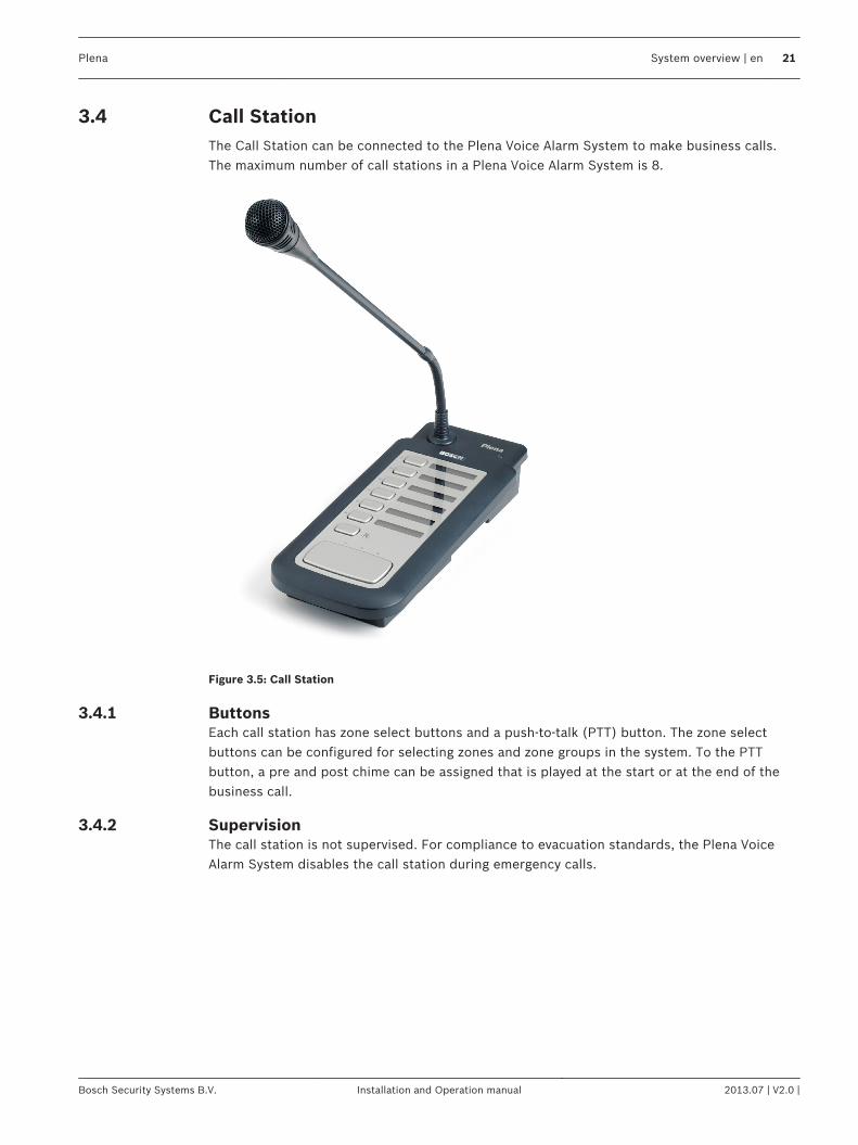
Call StationThe Call Station can be connected to the Plena Voice Alarm System to make business calls.The maximum number of call stations in a Plena Voice Alarm System is 8.
Figure 3.5: Call Station
ButtonsEach call station has zone select buttons and a push-to-talk (PTT) button. The zone selectbuttons can be configured for selecting zones and zone groups in the system. To the PTTbutton, a pre and post chime can be assigned that is played at the start or at the end of thebusiness call.
SupervisionThe call station is not supervised. For compliance to evacuation standards, the Plena VoiceAlarm System disables the call station during emergency calls.
3.4
3.4.1
3.4.2
Plena System overview | en 21
Bosch Security Systems B.V. Installation and Operation manual 2013.07 | V2.0 |
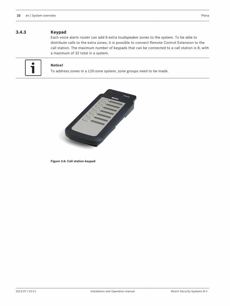
KeypadEach voice alarm router can add 6 extra loudspeaker zones to the system. To be able todistribute calls to the extra zones, it is possible to connect Remote Control Extension to thecall station. The maximum number of keypads that can be connected to a call station is 8, witha maximum of 32 total in a system.
Notice!
To address zones in a 120-zone system, zone groups need to be made.
Figure 3.6: Call station keypad
3.4.3
22 en | System overview Plena
2013.07 | V2.0 | Installation and Operation manual Bosch Security Systems B.V.
Controls, connectors and indicators
Plena
ON
12
34
56
78
2
39
5
1
4
8
6 7
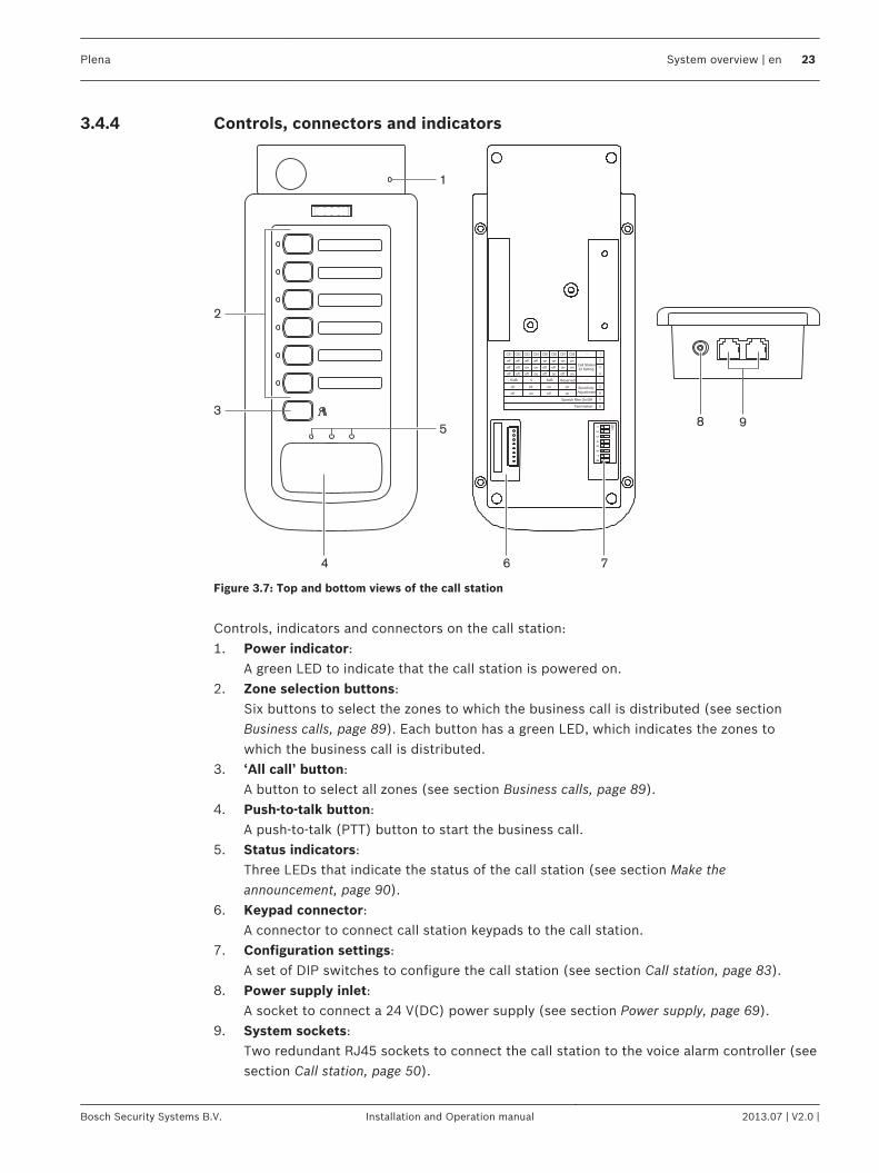
Figure 3.7: Top and bottom views of the call station
Controls, indicators and connectors on the call station:1. Power indicator:
A green LED to indicate that the call station is powered on.2. Zone selection buttons:
Six buttons to select the zones to which the business call is distributed (see sectionBusiness calls, page 89). Each button has a green LED, which indicates the zones towhich the business call is distributed.
3. ‘All call’ button:A button to select all zones (see section Business calls, page 89).
4. Push-to-talk button:A push-to-talk (PTT) button to start the business call.
5. Status indicators:Three LEDs that indicate the status of the call station (see section Make theannouncement, page 90).
6. Keypad connector:A connector to connect call station keypads to the call station.
7. Configuration settings:A set of DIP switches to configure the call station (see section Call station, page 83).
8. Power supply inlet:A socket to connect a 24 V(DC) power supply (see section Power supply, page 69).
9. System sockets:Two redundant RJ45 sockets to connect the call station to the voice alarm controller (seesection Call station, page 50).
3.4.4
Plena System overview | en 23
Bosch Security Systems B.V. Installation and Operation manual 2013.07 | V2.0 |
Call Station Keypad
Plena
1
2 2
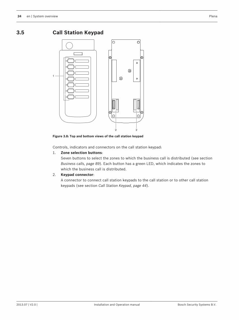
Figure 3.8: Top and bottom views of the call station keypad
Controls, indicators and connectors on the call station keypad:1. Zone selection buttons:
Seven buttons to select the zones to which the business call is distributed (see sectionBusiness calls, page 89). Each button has a green LED, which indicates the zones towhich the business call is distributed.
2. Keypad connector:A connector to connect call station keypads to the call station or to other call stationkeypads (see section Call Station Keypad, page 44).
3.5
24 en | System overview Plena
2013.07 | V2.0 | Installation and Operation manual Bosch Security Systems B.V.
Voice Alarm Remote Control
0 dB
-6dB
-20dB
Processor reset
Network
Call/EMG
Music/Spare
Ground short
Input
Mains
Battery
Zone1
Zone2
Zone3
Zone4
Zone5
Zone6
Alarm
Zone select
Plena Voice Alarm Remote Control
Fault Indicators
Zone select
Indicator test
EMG mic
Alert message
Alarm message
All call
Zone1 Zone2 Zone3 Zone4 Zone5 Zone6
Fault EMG
Ack
Reset
A B
Disabled
Message
EMG mic
RCP
Router
Design & QualityThe Netherlands
NL-4827HG-10
Plena Voice Alarm SystemRC PanelMax. input power300mA, 24V DCS/N.
PLN-V6RC
A035413
Mad
e in
Chin
a
N663
8900 199 60001
1 2 3 4 5
69121314
15171820
710
16192122232425
811
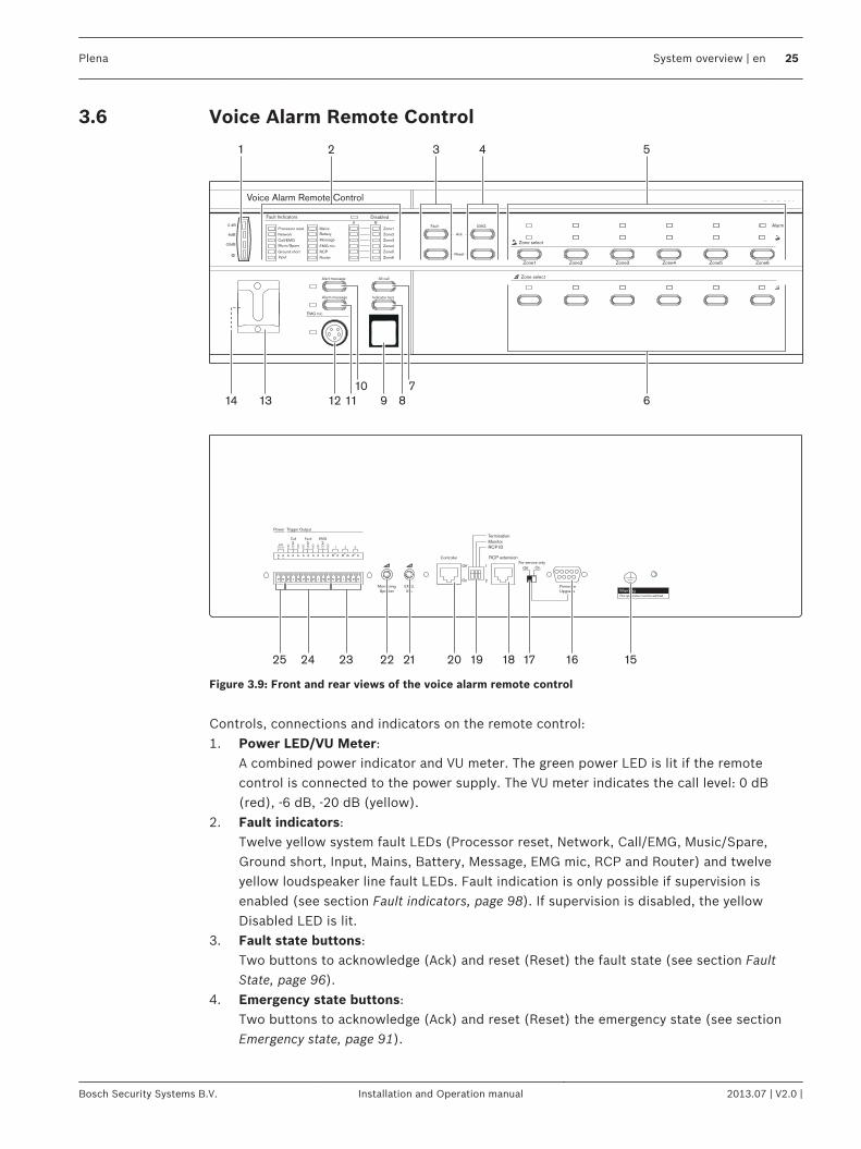
Figure 3.9: Front and rear views of the voice alarm remote control
Controls, connections and indicators on the remote control:1. Power LED/VU Meter:
A combined power indicator and VU meter. The green power LED is lit if the remotecontrol is connected to the power supply. The VU meter indicates the call level: 0 dB(red), -6 dB, -20 dB (yellow).
2. Fault indicators:Twelve yellow system fault LEDs (Processor reset, Network, Call/EMG, Music/Spare,Ground short, Input, Mains, Battery, Message, EMG mic, RCP and Router) and twelveyellow loudspeaker line fault LEDs. Fault indication is only possible if supervision isenabled (see section Fault indicators, page 98). If supervision is disabled, the yellowDisabled LED is lit.
3. Fault state buttons:Two buttons to acknowledge (Ack) and reset (Reset) the fault state (see section FaultState, page 96).
4. Emergency state buttons:Two buttons to acknowledge (Ack) and reset (Reset) the emergency state (see sectionEmergency state, page 91).
3.6
Plena System overview | en 25
Bosch Security Systems B.V. Installation and Operation manual 2013.07 | V2.0 |
5. Emergency call zone selectors:Six buttons to select the zones to which the emergency call must be distributed (seesection Emergency state, page 91). Each button has a green and a red LED. The six redLEDs indicate the zones that are selected for the emergency call. The six green LEDsindicate the zones in which a business call is running.
6. BGM zone selectors:Six buttons to select the zones to which the BGM is distributed (see section Backgroundmusic, page 88). Each button has a green LED. The six green LEDs indicate the zones towhich BGM is distributed. It is not possible to control the volume of the BGM with theremote control.
7. All call button:A button to select all zones. This button is only available in the emergency state (seesection Emergency state, page 91).
8. Indicator test button:A button to test all LEDs on the front panel of the remote control and all connectedremote control extensions. All LEDs are lit as long as the button is pushed (see sectionFault State, page 96).
9. Emergency button:A push button to put the system in the emergency state (see section Emergency state,page 91).
10. Alert message button:A button to select the alert message. This button is only available in the emergency state(see section Emergency state, page 91).
11. Alarm message button:A button to select the default alarm message. This button is only available in theemergency state (see section Emergency state, page 91).
12. Microphone socket:A socket to connect the hand-held emergency microphone (see section Emergencymicrophone, page 49).
13. Bracket:A bracket for the hand-held emergency microphone that is supplied with the remotecontrol.
14. Monitoring loudspeaker:Built-in monitoring loudspeaker.
15. Ground:A connection to electrically ground the remote control.
16. Firmware upgrade connector:An RS232 connector to connect a PC to upgrade the firmware of the remote control.
17. Firmware upgrade switch:A switch to upgrade the firmware of the remote control.
18. Remote control extension sockets:Two redundant RJ45 sockets to connect remote control extensions to the remote control(see section Remote control extensions, page 70).
19. Configuration settings:A set of DIP switches to configure the remote control (see section Remote control, page85).
20. Controller socket:One RJ45 socket to connect the remote control to the voice alarm controller (see sectionVoice alarm controller, page 70).
26 en | System overview Plena
2013.07 | V2.0 | Installation and Operation manual Bosch Security Systems B.V.
21. Emergency microphone volume control:A rotary knob to set the volume of the hand-held emergency microphone.
22. Monitoring speaker volume control:A rotary knob to set the volume of the monitoring loudspeaker.
23. Trigger outputs:Three general purpose trigger outputs. For future use.
24. Status outputs:Three status outputs to send the status of the Plena Voice Alarm System to third partyequipment (see section Status output contacts, page 70).
25. 24 V DC input:One 24 V(DC) input to connect the remote control panel to a power supply (see sectionPower, page 71).
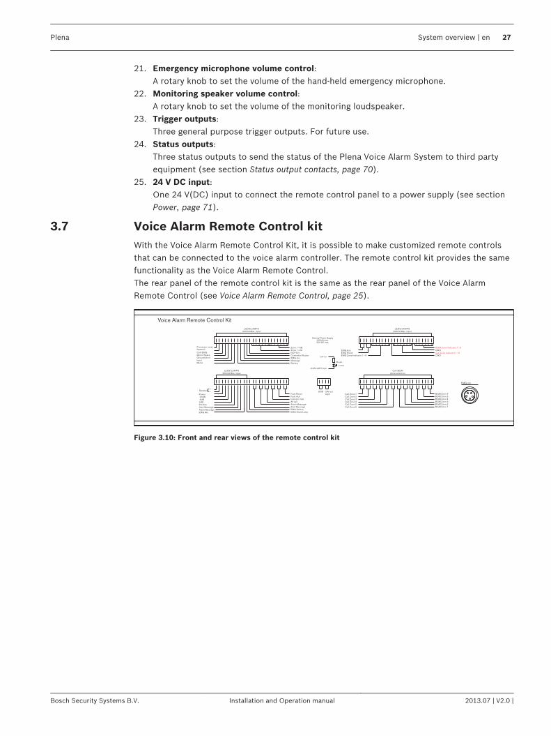
Voice Alarm Remote Control kitWith the Voice Alarm Remote Control Kit, it is possible to make customized remote controlsthat can be connected to the voice alarm controller. The remote control kit provides the samefunctionality as the Voice Alarm Remote Control.The rear panel of the remote control kit is the same as the rear panel of the Voice AlarmRemote Control (see Voice Alarm Remote Control, page 25).
BGM Zone 1
BGM Zone 6BGM Zone 5BGM Zone 4BGM Zone 3BGM Zone 2
Call Zone 6
Speaker
Power
EMG AckEMG Reset
Processor resetNetwork
Call/EMG.Music/SpareGround shortInputMains
Zone 1~6BZone 1~6ARCP Ext.
Controller/RouterEMG micMessageBattery
Call Zone Indicator 1~6EMG Zone Indicator 1~6
GNDBGM Zone Indicator 1~6
GND
EMG State Lamp
+_
-20dB
-6dB0dBDisable
Alert MessageAlarm Message
EMG Mic
EMG SwitchAlert MessageAlarm MessageAll callIndicator testFault AckFault Reset Call Zone 1
Call Zone 2Call Zone 3Call Zone 4Call Zone 5
Plena Voice Alarm Remote Control Kit
LEDS/LAMPS200mA Max. input
LEDS/LAMPS200mA Max. input
LEDS/LAMPS200mA Max. input
Call/BGMZone selection
GND 24V out0.2A
5K ohm
< 5mA
24V out
LEDS/LAMPS input
1 2 3 4 5 6 1 2 3 4 5 6 1 2 3 4 5 61 2 3 4 5 61 2 3 4 5 6
EMG mic
External Power Supply200mA max.50V DC max.
Figure 3.10: Front and rear views of the remote control kit
3.7
Plena System overview | en 27
Bosch Security Systems B.V. Installation and Operation manual 2013.07 | V2.0 |
Remote Control Extension
Plena Remote Control Extension
0 dB
-6dB
-20dB
B
Processor reset
Network
Call/EMG
Music/Spare
Ground short
Input
Mains
Battery
Zone1
Zone2
Zone3
Zone4
Zone5
Zone6
Alarm
Zone select
A
Fault Indicators
Zone select
Zone1 Zone2 Zone3 Zone4 Zone5 Zone6
6
1...9
ID
1234
5 7
98
RCP ext. In RCP ext. Out
Off On
Termination
FirmwareUpgrade
For service only
Off On
WarningThis apparatus must be earthed
Trigger OutputPower
24VDC In 321
Fault
Design & QualityThe Netherlands
NL-4827HG-10
Plena Voice Alarm SystemRC Panel ExtensionMax. input power200mA, 24V DCS/N.
PLN-V6RCE
A035413
Mad
e in
Chin
a
N663
8900 199 80001
NC
NO
CO
M
1 2 3
4
567910 8111213
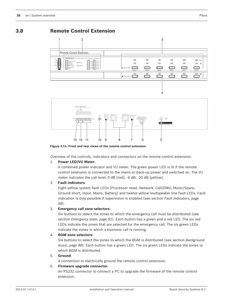
Figure 3.11: Front and rear views of the remote control extension
Overview of the controls, indicators and connectors on the remote control extension:1. Power LED/VU Meter:
A combined power indicator and VU meter. The green power LED is lit if the remotecontrol extension is connected to the mains or back-up power and switched on. The VUmeter indicates the call level: 0 dB (red), -6 dB, -20 dB (yellow).
2. Fault indicators:Eight yellow system fault LEDs (Processor reset, Network, Call/EMG, Music/Spare,Ground short, Input, Mains, Battery) and twelve yellow loudspeaker line fault LEDs. Faultindication is only possible if supervision is enabled (see section Fault indicators, page98).
3. Emergency call zone selectors:Six buttons to select the zones to which the emergency call must be distributed (seesection Emergency state, page 91). Each button has a green and a red LED. The six redLEDs indicate the zones that are selected for the emergency call. The six green LEDsindicate the zones in which a business call is running.
4. BGM zone selectors:Six buttons to select the zones to which the BGM is distributed (see section Backgroundmusic, page 88). Each button has a green LED. The six green LEDs indicate the zones towhich BGM is distributed.
5. Ground:A connection to electrically ground the remote control extension.
6. Firmware upgrade connector:An RS232 connector to connect a PC to upgrade the firmware of the remote controlextension.
3.8
28 en | System overview Plena
2013.07 | V2.0 | Installation and Operation manual Bosch Security Systems B.V.
7. Firmware upgrade switch:A switch to upgrade the firmware of the remote control extension.
8. System sockets:One RJ45 socket to connect the remote control extension to the remote control (seesection Remote control extensions, page 70).
9. Configuration settings:A termination switch for the Remote Control Extension and 0-9 / 10-19 switch (seesection Remote control extension, page 86).
10. Remote control extension ID:A rotary switch to set the ID of the remote control extension (see section Remote controlextension, page 86).
11. Trigger outputs:Three general purpose trigger outputs. For future use.
12. Status output:One status output to send the status of the Plena Voice Alarm System to third partyequipment (see section Status output contacts, page 73).
13. 24 V DC input:One 24 V(DC) input to connect the remote control panel to a power supply (see sectionPower, page 73).
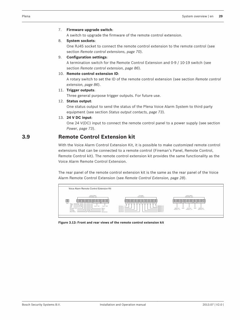
Remote Control Extension kitWith the Voice Alarm Control Extension Kit, it is possible to make customized remote controlextensions that can be connected to a remote control (Fireman’s Panel, Remote Control,Remote Control kit). The remote control extension kit provides the same functionality as theVoice Alarm Remote Control Extension. The rear panel of the remote control extension kit is the same as the rear panel of the VoiceAlarm Remote Control Extension (see Remote Control Extension, page 28).
BGM Zone 1
BGM Zone 6BGM Zone 5BGM Zone 4BGM Zone 3BGM Zone 2
Call Zone 6
Call Zone 1Call Zone 2Call Zone 3Call Zone 4Call Zone 5
Power-16dB
-6dB0dB
Processor resetNetwork
Call/EMGMusic/Spare
1 2 3 4 5 6
Zone 1~6A Zone 1~6B
BatteryMains
Input
Ground short
EMG ZoneIndicator 1~6
GND Call ZoneIndicator 1~6
GND BGM ZoneIndicator 1~6
Plena Voice Alarm Remote Control Extension Kit
GND
Call/BGMZone selection
LEDS/LAMPS200mA Max. input
LEDS/LAMPS200mA Max. input
1 2 3 4 5 6 1 2 3 4 5 6 1 2 3 4 5 6 1 2 3 4 5 6
Figure 3.12: Front and rear views of the remote control extension kit
3.9
Plena System overview | en 29
Bosch Security Systems B.V. Installation and Operation manual 2013.07 | V2.0 |
Fireman’s Panel
Plena Fireman's Panel
EMG mic
Fault Indicators
Processor reset
Network
Call/EMG
Music/Spare
Ground short
Input
A
B
A
B
A
B
Zone1
Zone2
Zone3
Disable
For service only
On1
2
Termination
RCP ID
Controller
MonitoringSpeaker Warning
This apparatus must be earthed
Trigger Output
24VDC In N
C
NO
CO
M
Call Fault EMG
321
Power
NC
NO
CO
M
NC
NO
CO
M
EMG.Mic
Monitor
Off
On
Off
FirmwareUpgrade
EmergencyAcknowledge
EmergencyReset
FaultAcknowledge
Fault Reset
Emergency
Mains
Battery
Message
EMG mic
RCP
Router
A
B
A
B
A
B
Zone4
Zone5
Zone6
Indicator test
Reserve
Monitor Speaker
CallAlarmMessage
Design & QualityThe Netherlands
NL-4827HG-10
Plena Voice Alarm SystemFireman's PanelMax. input power300mA, 24V DCS/N.
PLN-V1FP
A035413
Mad
e in
Chin
a
N663
8900 199 70501
0 dB
-6dB
-20dB
1 2 3 4 5 6 7 8
9
10121315 11141617181920
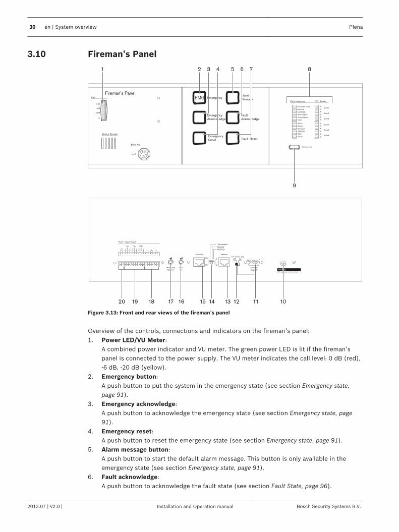
Figure 3.13: Front and rear views of the fireman’s panel
Overview of the controls, connections and indicators on the fireman’s panel:1. Power LED/VU Meter:
A combined power indicator and VU meter. The green power LED is lit if the fireman’spanel is connected to the power supply. The VU meter indicates the call level: 0 dB (red),-6 dB, -20 dB (yellow).
2. Emergency button:A push button to put the system in the emergency state (see section Emergency state,page 91).
3. Emergency acknowledge:A push button to acknowledge the emergency state (see section Emergency state, page91).
4. Emergency reset:A push button to reset the emergency state (see section Emergency state, page 91).
5. Alarm message button:A push button to start the default alarm message. This button is only available in theemergency state (see section Emergency state, page 91).
6. Fault acknowledge:A push button to acknowledge the fault state (see section Fault State, page 96).
3.10
30 en | System overview Plena
2013.07 | V2.0 | Installation and Operation manual Bosch Security Systems B.V.
7. Fault reset:A push button to reset the fault state (see section Fault State, page 96).
8. Fault indicators:Twelve yellow system fault LEDs (Processor reset, Network, Call/EMG, Music/Spare,Ground short, Input, Mains, Battery, Message, EMG mic, RCP and Router) and twelveyellow loudspeaker line fault LEDs. Fault indication is only possible if supervision isenabled (see section Fault indicators, page 98). If supervision is disabled, the yellowDisabled LED is lit.
9. Indicator test button:A button to test all LEDs on the front panel of the fireman’s panel and all connectedremote control extensions. All LEDs are lit as long as the button is pushed (see sectionFault State, page 96).
10. Ground:A connection to electrically ground the fireman’s panel.
11. Firmware upgrade connector:An RS232 connector to connect a PC to upgrade the firmware of the fireman’s panel.
12. Firmware upgrade switch:A switch to upgrade the firmware of the fireman’s panel.
13. Remote control extension sockets:Two redundant RJ45 sockets to connect remote control extensions to the fireman’s panel(see section Remote control extensions, page 70).
14. Configuration settings:A set of DIP switches to configure the fireman’s panel (see section Remote control, page85).
15. Controller socket:One RJ45 socket to connect the fireman’s panel to the voice alarm controller (see sectionVoice alarm controller, page 70).
16. Emergency microphone volume control:A rotary knob to set the volume of the hand-held emergency microphone.
17. Monitoring speaker volume control:A rotary knob to set the volume of the monitoring loudspeaker.
18. Trigger outputs:Three general purpose trigger outputs. For future use.
19. Status outputs:Three status outputs to send the status of the Plena Voice Alarm System to third partyequipment (see section Status output contacts, page 74).
20. 24 V DC input:One 24 V(DC) input to connect the fireman’s panel to a power supply (see section Power,page 74).
Plena System overview | en 31
Bosch Security Systems B.V. Installation and Operation manual 2013.07 | V2.0 |
End Of Line detection boardThe End Of Line (EOL) detection board makes a continuous check of the integrity of theloudspeaker line based on a pilot tone. This check is in addition to the check given by theimpedance measurement. The pilot tone is independent of the quantity of the loudspeakers inthe system or the load on the speaker cables.The EOL is installed in the speaker cabinet at the furthest point on a loudspeaker line. Whenthe EOL detects a pilot tone that is given by the voice alarm system, the loudspeaker lineshave no fault. The EOL trigger output is closed and the LED lights up to show that the lineshave a pilot tone signal.If the loudspeaker cable has a fault, the pilot tone stops. The EOL circuit becomes open,which is detected by the Voice Alarm Controller.One EOL board can be installed to give a single fault indication per zone or more than one canbe installed on a single fault input to check the integrity of a loudspeaker line with severalbranches. When more than one EOL board is installed, the configuration is called a daisy-chain.When a fault is detected by the Voice Alarm Controller, to find the EOL board that detects thefailure, every individual board must be checked.
Application examples
SchoolsSchools are typical example of applications with a large number of zones each with a relativelylow output power requirement per zone. The main priorities are speech intelligibility andcompliance with IEC 60849 standard (or equivalent). In addition to mandatory voice alarmfunctionality for evacuating staff and students, EVAC systems for schools should also includechime tones for notifying the start/finish of lessons, plus public address functionality forindividually calling classrooms or public area. BGM is not essential. Since a classroom has alow ambient noise level, 1 loudspeaker is usually sufficient, keeping the total powerrequirement relatively low. Outside areas such as playgrounds and sports fields will requireweatherproof horn loudspeakers.
Summary of requirements– Typically 20 to 60 zones (in high schools)– Speech intelligibility is the main priority– Low power requirement (1 loudspeaker) per classroom– Fireman’s panel by main entrance– Call station in main office– Additional public address functions such as chime tones desirable– BGM in recreation areas is optional
Solution for a 30-zone systemThe Plena Voice Alarm System Controller handles message routing to 6 zones, the remaining24 zones require four additional 6-zone routers. The office is equipped with a call station pluskeypads for individually addressing zones, while a fireman’s panel (with overall priority) isbuilt in by the main entrance.
Power requirementsThe system controller features a built‑in 240 W power amplifier, making it possible to drive upto 40 loudspeakers with a power handling capacity of 6 W each. This is sufficient for amedium-sized high school with 24 classrooms, 4 toilets/changing rooms, a staff meeting room
3.11
3.12
3.12.1
32 en | System overview Plena
2013.07 | V2.0 | Installation and Operation manual Bosch Security Systems B.V.
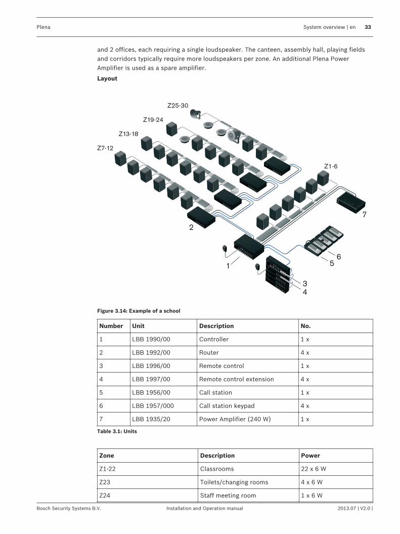
and 2 offices, each requiring a single loudspeaker. The canteen, assembly hall, playing fieldsand corridors typically require more loudspeakers per zone. An additional Plena PowerAmplifier is used as a spare amplifier.
Layout
2
Z7-12
Z13-18
Z19-24
Z25-30
Z1-6
7
5
3
4
6
1
Figure 3.14: Example of a school
Number Unit Description No.
1 LBB 1990/00 Controller 1 x
2 LBB 1992/00 Router 4 x
3 LBB 1996/00 Remote control 1 x
4 LBB 1997/00 Remote control extension 4 x
5 LBB 1956/00 Call station 1 x
6 LBB 1957/000 Call station keypad 4 x
7 LBB 1935/20 Power Amplifier (240 W) 1 x
Table 3.1: Units
Zone Description Power
Z1-22 Classrooms 22 x 6 W
Z23 Toilets/changing rooms 4 x 6 W
Z24 Staff meeting room 1 x 6 W
Plena System overview | en 33
Bosch Security Systems B.V. Installation and Operation manual 2013.07 | V2.0 |
Zone Description Power
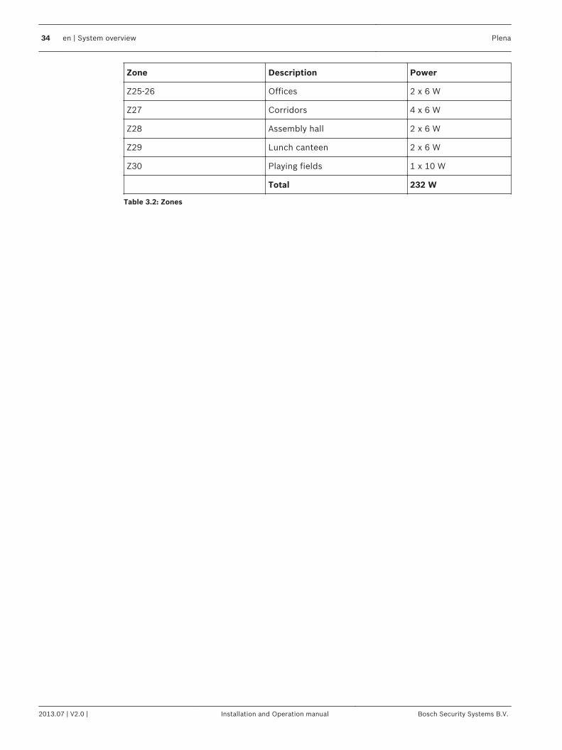
Z25-26 Offices 2 x 6 W
Z27 Corridors 4 x 6 W
Z28 Assembly hall 2 x 6 W
Z29 Lunch canteen 2 x 6 W
Z30 Playing fields 1 x 10 W
Total 232 W
Table 3.2: Zones
34 en | System overview Plena
2013.07 | V2.0 | Installation and Operation manual Bosch Security Systems B.V.

Swimming poolSwimming pools and other indoor sports and recreational facilities are typical examples ofsmaller applications with few zones. The main priorities are excellent speech intelligibility andcompliance with IEC 60849 standard (and its national equivalents), although music in differentareas is optional. An EVAC system for a swimming pool requires voice alarm functionality withpublic address functionality for regular announcements and background music (optional). Toensure that all visitors in the relatively noisy pool area hear emergency messages, the poweroutput for that zone is relatively high. Other areas, such as the changing rooms and offices,have lower power requirements.
Summary of requirements– Typically up to 6 zones– Speech intelligibility is the main priority– High power requirement in the noisy pool area– Fireman’s panel by fire exit– Call station in office/reception– Additional public address functions for announcements– BGM
Solution for a 5-zone systemThe Plena Voice Alarm System controller handles routing to up to 6 zones, so no additionalrouters are required. The office/reception is equipped with a call station plus keypad forindividually addressing zones, while a fireman’s panel (with overall priority) is built‑in by theemergency exit. The Plena Voice Alarm System is a two-channel system, so BGM can still beprovided in zones not receiving a call.
Power requirementsThe system controller has a built-in 240 W power amplifier, making it possible to drive up to40 loudspeakers with a power handling capacity of 6 W each. The pool area requires highpower music loudspeakers qualified for use in a high humidity atmosphere. The snack baruses cabinet loudspeakers for music reproduction. The zones are defined as indicated in thetable. An additional Plena Power Amplifier is used for two-channel operation and as a spareamplifier.
3.12.2
Plena System overview | en 35
Bosch Security Systems B.V. Installation and Operation manual 2013.07 | V2.0 |
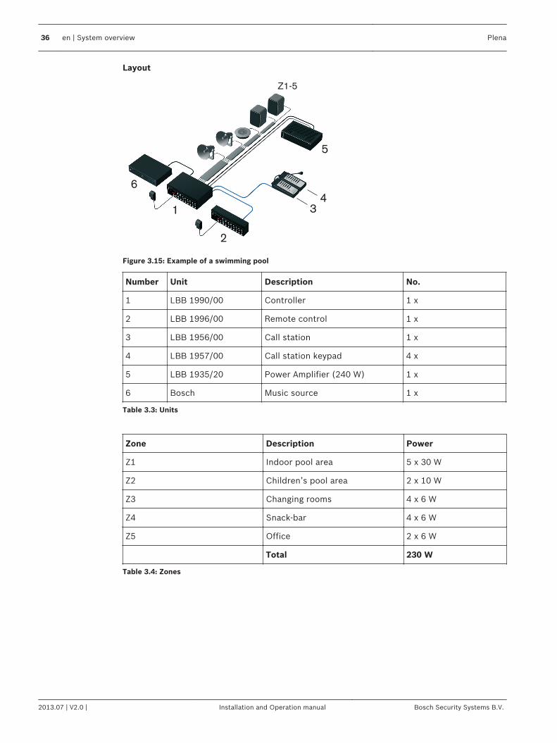
Layout
6
1
Z1-5
5
3
2
4
Figure 3.15: Example of a swimming pool
Number Unit Description No.
1 LBB 1990/00 Controller 1 x
2 LBB 1996/00 Remote control 1 x
3 LBB 1956/00 Call station 1 x
4 LBB 1957/00 Call station keypad 4 x
5 LBB 1935/20 Power Amplifier (240 W) 1 x
6 Bosch Music source 1 x
Table 3.3: Units
Zone Description Power
Z1 Indoor pool area 5 x 30 W
Z2 Children’s pool area 2 x 10 W
Z3 Changing rooms 4 x 6 W
Z4 Snack-bar 4 x 6 W
Z5 Office 2 x 6 W
Total 230 W
Table 3.4: Zones
36 en | System overview Plena
2013.07 | V2.0 | Installation and Operation manual Bosch Security Systems B.V.
Shopping mallShopping malls are typical example of applications with a large number of zones with varyingoutput power requirements per zone. The priorities are speech intelligibility and compliancewith IEC 60849 standard (and its national equivalents). In addition to mandatory voice alarmfunctionality for evacuating the public and shop personnel, an EVAC system for shoppingcenters can have BGM for the public areas. It should be possible to individually call each shopor store. During emergency messages, each shop’s BGM volume control is automaticallyoverridden. Additional public address functionality for making general public announcementsis an optional requirement.
Summary of requirements– Typically up to 60 zones– Speech intelligibility is the main priority– Variable power requirement per zone– Call station in security control room– Additional public address functionality (non-emergency)– BGM in public areas– BGM music with local override in shops
Solution for a 54-zone systemA Plena Voice Alarm System Controller handles routing to 6 zones, the remaining 48 zonesrequire eight 6‑zone routers. The security control room is equipped with a remote controlpanel and call station plus keypads for individually addressing zones and BGM for the publicareas, while the controller unit and routers are located in a fire-resistant cabinet or basement.Fireman’s panel (with overall priority) is built-in close to the main entrance or emergency exit(subject to relevant local regulations). The Plena Voice Alarm System is a two-channel system,so BGM can still be provided in zones not receiving a call.
Power requirementsEach zone will have varying power requirements, ranging from small shops with a singleloudspeaker to department stores with several floors and more loudspeakers. Parking garagesand open-air walkways will require weatherproof sound projectors or horn loudspeakers. Tofacilitate phased evacuation from different levels of the shopping center, public areas aredivided into zones. Additional Plena Power Amplifiers are incorporated to provide additionalpower, two-channel operation and for use as a spare amplifier.
3.12.3
Plena System overview | en 37
Bosch Security Systems B.V. Installation and Operation manual 2013.07 | V2.0 |
Layout
2
Z49-54
Z43-48
Z37-42
Z31-36
Z25-30
Z19-24
Z13-18
Z7-12
Z1-6
9
8
8
6
3
710
1
4
5
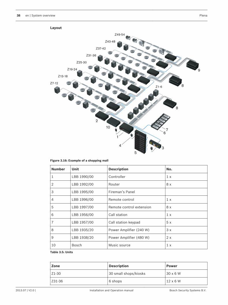
Figure 3.16: Example of a shopping mall
Number Unit Description No.
1 LBB 1990/00 Controller 1 x
2 LBB 1992/00 Router 8 x
3 LBB 1995/00 Fireman’s Panel
4 LBB 1996/00 Remote control 1 x
5 LBB 1997/00 Remote control extension 8 x
6 LBB 1956/00 Call station 1 x
7 LBB 1957/00 Call station keypad 5 x
8 LBB 1935/20 Power Amplifier (240 W) 3 x
9 LBB 1938/20 Power Amplifier (480 W) 2 x
10 Bosch Music source 1 x
Table 3.5: Units
Zone Description Power
Z1-30 30 small shops/kiosks 30 x 6 W
Z31-36 6 shops 12 x 6 W
38 en | System overview Plena
2013.07 | V2.0 | Installation and Operation manual Bosch Security Systems B.V.
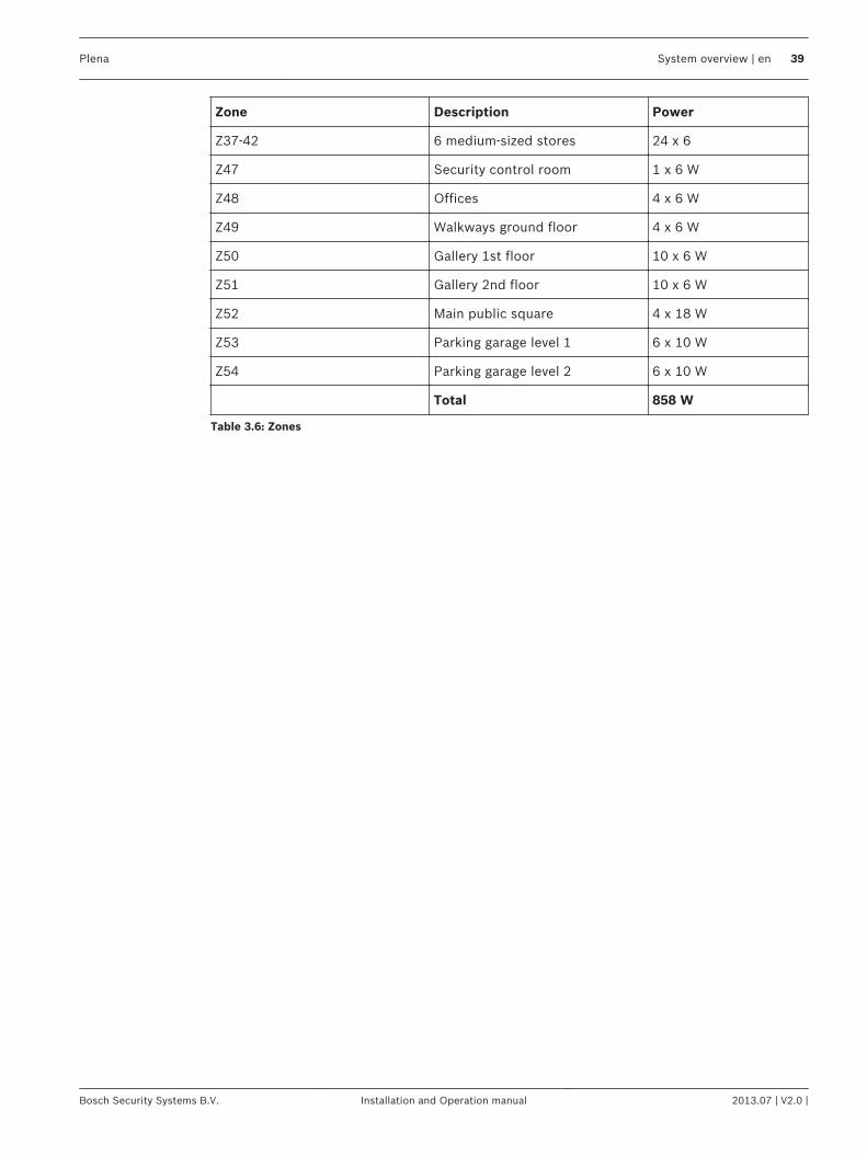
Zone Description Power
Z37-42 6 medium-sized stores 24 x 6
Z47 Security control room 1 x 6 W
Z48 Offices 4 x 6 W
Z49 Walkways ground floor 4 x 6 W
Z50 Gallery 1st floor 10 x 6 W
Z51 Gallery 2nd floor 10 x 6 W
Z52 Main public square 4 x 18 W
Z53 Parking garage level 1 6 x 10 W
Z54 Parking garage level 2 6 x 10 W
Total 858 W
Table 3.6: Zones
Plena System overview | en 39
Bosch Security Systems B.V. Installation and Operation manual 2013.07 | V2.0 |
HotelSmaller hotels are typical examples of applications with relatively few zones, each with amedium to high output power requirement. The priorities are speech intelligibility andcompliance with IEC 60849 standard. In addition to mandatory voice alarm functionality forevacuating guests and staff, an EVAC system for a hotel should also include BGM in therestaurant, bar and lobby, plus public address functionality for general paging. To ensure thatall guests hear an emergency message, the power output per zone is relatively high. Outsideareas such as car parking garages, require weatherproof horn loudspeakers.
Summary of requirements– Typically 10 to 20 zones in small hotels– Speech intelligibility is the main priority– High power requirement (multiple loudspeakers) per floor– Fireman’s panel by fire exit– Call stations in reception and office– Additional public address functions for paging guests– BGM in lobby and restaurant
Solution for a 12-zone systemA Plena Voice Alarm System Controller handles routing to up to 6 zones, the additional 6zones require a router. Both the reception and office are equipped with call stations pluskeypads for individually addressing zones, while a fireman’s panel (with overall priority) isbuilt‑in by the emergency exit. The Plena Voice Alarm System is a two‑channel system, so BGMcan still be provided in zones not receiving a call.
Power requirementsThe system controller features a built-in 240 W power amplifier, able to drive up to 40loudspeakers (6 W). Additional Plena Power Amplifiers are incorporated to provide additionalpower, two‑channel operation and spare amplification. To facilitate phased evacuation fromdifferent floors of the hotel, guest areas are divided into separate zones, each fitted with 13ceiling loudspeakers in the corridors. The bar uses cabinet loudspeakers, while the parkinggarage uses weatherproof horn loudspeakers.
3.12.4
40 en | System overview Plena
2013.07 | V2.0 | Installation and Operation manual Bosch Security Systems B.V.
Layout
2
9
1
Z7-12
Z1-6
7
8
5
3
6
4
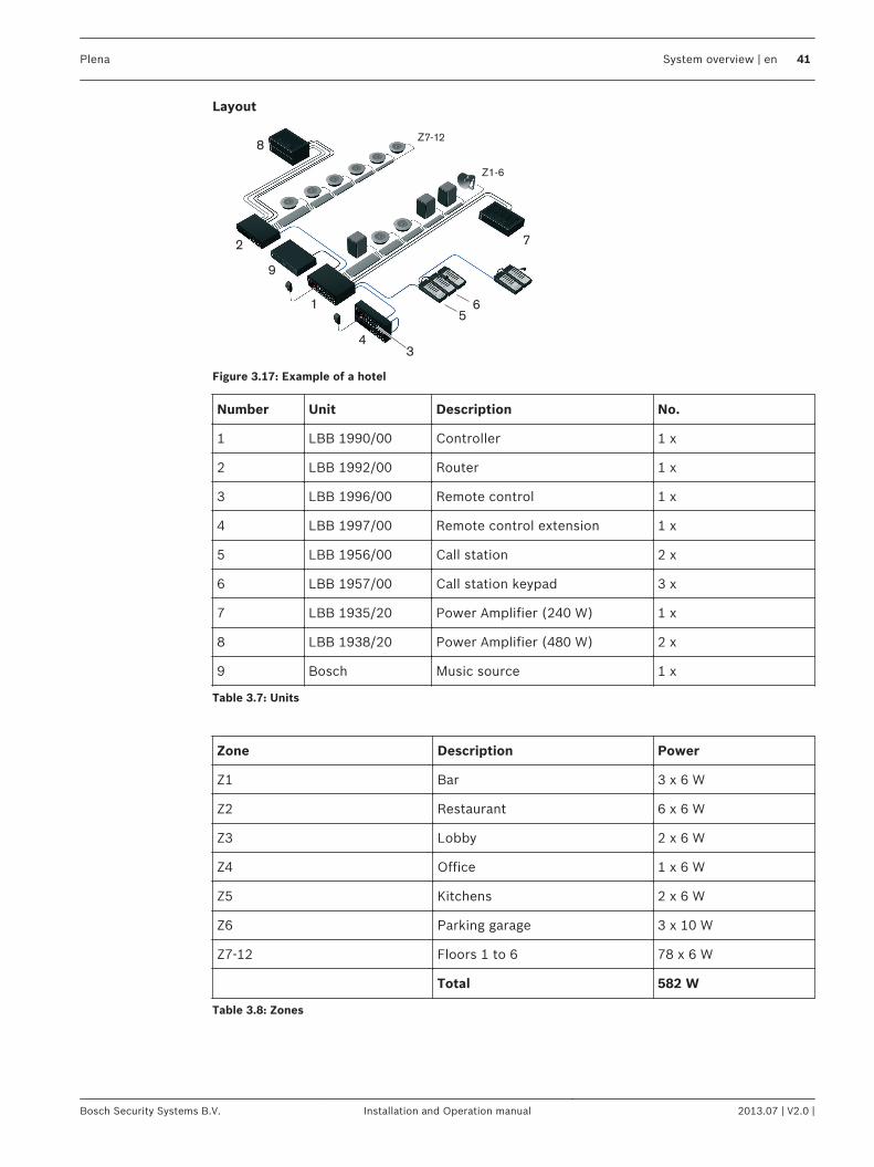
Figure 3.17: Example of a hotel
Number Unit Description No.
1 LBB 1990/00 Controller 1 x
2 LBB 1992/00 Router 1 x
3 LBB 1996/00 Remote control 1 x
4 LBB 1997/00 Remote control extension 1 x
5 LBB 1956/00 Call station 2 x
6 LBB 1957/00 Call station keypad 3 x
7 LBB 1935/20 Power Amplifier (240 W) 1 x
8 LBB 1938/20 Power Amplifier (480 W) 2 x
9 Bosch Music source 1 x
Table 3.7: Units
Zone Description Power
Z1 Bar 3 x 6 W
Z2 Restaurant 6 x 6 W
Z3 Lobby 2 x 6 W
Z4 Office 1 x 6 W
Z5 Kitchens 2 x 6 W
Z6 Parking garage 3 x 10 W
Z7-12 Floors 1 to 6 78 x 6 W
Total 582 W
Table 3.8: Zones
Plena System overview | en 41
Bosch Security Systems B.V. Installation and Operation manual 2013.07 | V2.0 |
Calls and prioritiesAs the Plena Voice Alarm System is a public address and emergency sound system, it is usedto distribute background music, business calls and emergency calls.
PriorityTo each call, a priority is assigned. When two or more calls are addressed to the same zone orneed shared resources (e.g. the internal message manager of the voice alarm controller), thecall with the lower priority is stopped immediately and the call with the higher priority isstarted. The priority of a call depends on the part of the system that started the call and mustbe configured with the configuration software.
Notice!
See the Configuration Software Manual for more information about the configuration
software.
When two or more calls with the same priority are addressed to the same zone or need sharedresources (e.g. the internal message manager of the voice alarm controller), the oldest call isstopped immediately and the youngest call is started. An exception to this rule are mergeablemessages (see section Mergeable messages, page 42).
Mergeable messagesWhen two or more calls are started that are based on the same mergeable message templateand have the same priority, the calls are merged. The youngest call will not stop the oldest callin this case. Mergeable message can be created with the configuration software.
Business callA business call is a call that is made when the system is in the normal state. Business callsalways have a priority between 2 and 8 and can be started with:– Business trigger inputs– Call stations– The mic/line input with VOX functionality of the voice alarm controller
Emergency callAn emergency call is a call that is made when the system is in the emergency state. Emergencycalls have a certain priority in the configuration software, and can be started with:– Emergency trigger inputs (priority between 2 and 14)– The hand-held emergency microphone of the voice alarm controller (priority between 9
and 19)– The mic/line input with VOX functionality of the voice alarm controller (priority between 2
and 14)
3.13
3.13.1
3.13.2
3.13.3
3.13.4
42 en | System overview Plena
2013.07 | V2.0 | Installation and Operation manual Bosch Security Systems B.V.
Installation
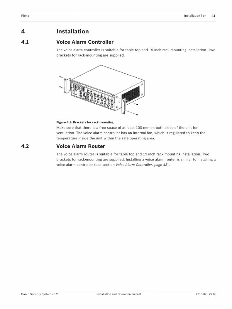
Voice Alarm ControllerThe voice alarm controller is suitable for table‑top and 19‑inch rack-mounting installation. Twobrackets for rack-mounting are supplied.
Figure 4.1: Brackets for rack-mounting
Make sure that there is a free space of at least 100 mm on both sides of the unit forventilation. The voice alarm controller has an internal fan, which is regulated to keep thetemperature inside the unit within the safe operating area.
Voice Alarm RouterThe voice alarm router is suitable for table‑top and 19‑inch rack mounting installation. Twobrackets for rack-mounting are supplied. Installing a voice alarm router is similar to installing avoice alarm controller (see section Voice Alarm Controller, page 43).
4
4.1
4.2
Plena Installation | en 43
Bosch Security Systems B.V. Installation and Operation manual 2013.07 | V2.0 |
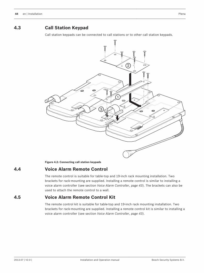
Call Station KeypadCall station keypads can be connected to call stations or to other call station keypads.
1122
4433
5566
77
1
2
3
Figure 4.2: Connecting call station keypads
Voice Alarm Remote ControlThe remote control is suitable for table‑top and 19‑inch rack mounting installation. Twobrackets for rack-mounting are supplied. Installing a remote control is similar to installing avoice alarm controller (see section Voice Alarm Controller, page 43). The brackets can also beused to attach the remote control to a wall.
Voice Alarm Remote Control KitThe remote control kit is suitable for table‑top and 19‑inch rack mounting installation. Twobrackets for rack-mounting are supplied. Installing a remote control kit is similar to installing avoice alarm controller (see section Voice Alarm Controller, page 43).
4.3
4.4
4.5
44 en | Installation Plena
2013.07 | V2.0 | Installation and Operation manual Bosch Security Systems B.V.
Remote Control ExtensionThe remote control extension is suitable for table‑top and 19‑inch rack mounting installation.Two brackets for rack-mounting are supplied. Installing a remote control extension is similarto installing a voice alarm controller (see section Voice Alarm Controller, page 43). Thebrackets can also be used to attach the remote control extension to a wall.
Remote Control Extension KitThe remote control extension kit is suitable for table‑top and 19‑inch rack mountinginstallation. Two brackets for rack-mounting are supplied. Installing a remote control kit issimilar to installing a voice alarm controller (see section Voice Alarm Controller, page 43).
End Of Line detection boardTo install an EOL, use these general notes:– An EOL board can only be installed in a 2‑channel system. The EOL board needs the
second amplifier to produce the pilot tone for the zones that are not in use. Refer tosection 2-Channel mode operation, page 78.
– The volume control on the VAC must be set to -9 dB or higher. The recommended settingis 0 dB. A lower dB setting attenuates the pilot‑tone.
Notice!
You must use either EOL or impedance measurement, not both.
Notice!
Do not connect the EOL board to the secondary side of a volume control.
The secondary side of a volume control can attenuate the pilot tone.
All inputs to a VAC or router that have an EOL input must be normally closed inputs. The EOLboard operates with a normally closed output and the configuration software is set to ActionOpen. Use another router to receive normally open inputs.
Notice!
During a call the pilot tone is absent in zones without a call or without background music. The
LED on the EOL board is dim. The EOL input is ignored during calls to avoid false fault
readings.
The short circuit check must be set in the configuration software.
Notice!
The EOL board detects a short circuit, but the EOL cannot detect where the short circuit is.
Notice!
It is possible for the LED to turn off before the contact is opened or vice versa. This level
difference is typically less than 500 mV.
4.6
4.7
4.8
Plena Installation | en 45
Bosch Security Systems B.V. Installation and Operation manual 2013.07 | V2.0 |
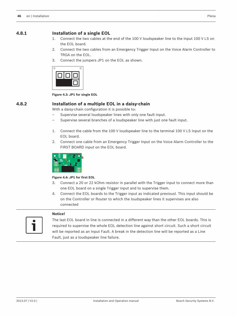
Installation of a single EOL1. Connect the two cables at the end of the 100 V loudspeaker line to the Input 100 V LS on
the EOL board.2. Connect the two cables from an Emergency Trigger Input on the Voice Alarm Controller to
TRGA on the EOL.3. Connect the jumpers JP1 on the EOL as shown.
Figure 4.3: JP1 for single EOL
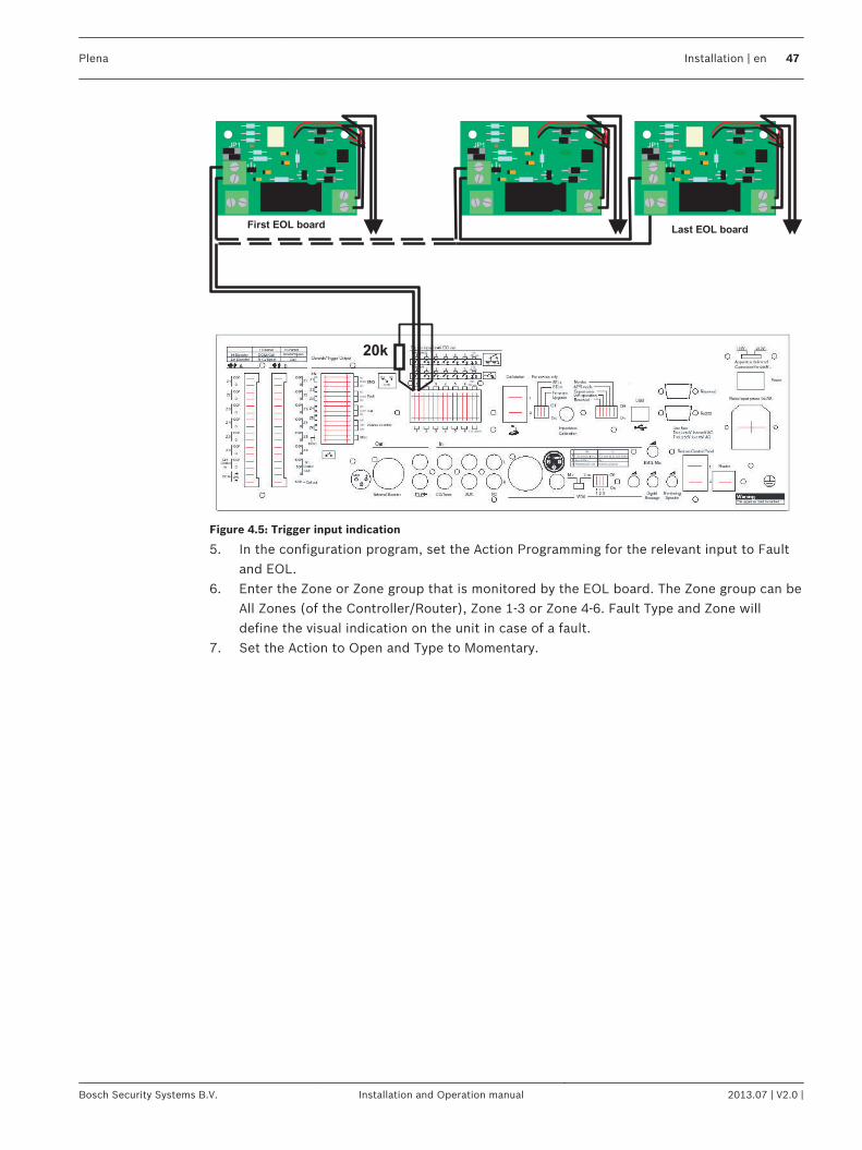
Installation of a multiple EOL in a daisy-chainWith a daisy‑chain configuration it is possible to:– Supervise several loudspeaker lines with only one fault input.– Supervise several branches of a loudspeaker line with just one fault input. 1. Connect the cable from the 100 V loudspeaker line to the terminal 100 V LS Input on the
EOL board.2. Connect one cable from an Emergency Trigger Input on the Voice Alarm Controller to the
FIRST BOARD input on the EOL board.
JP1
Figure 4.4: JP1 for first EOL
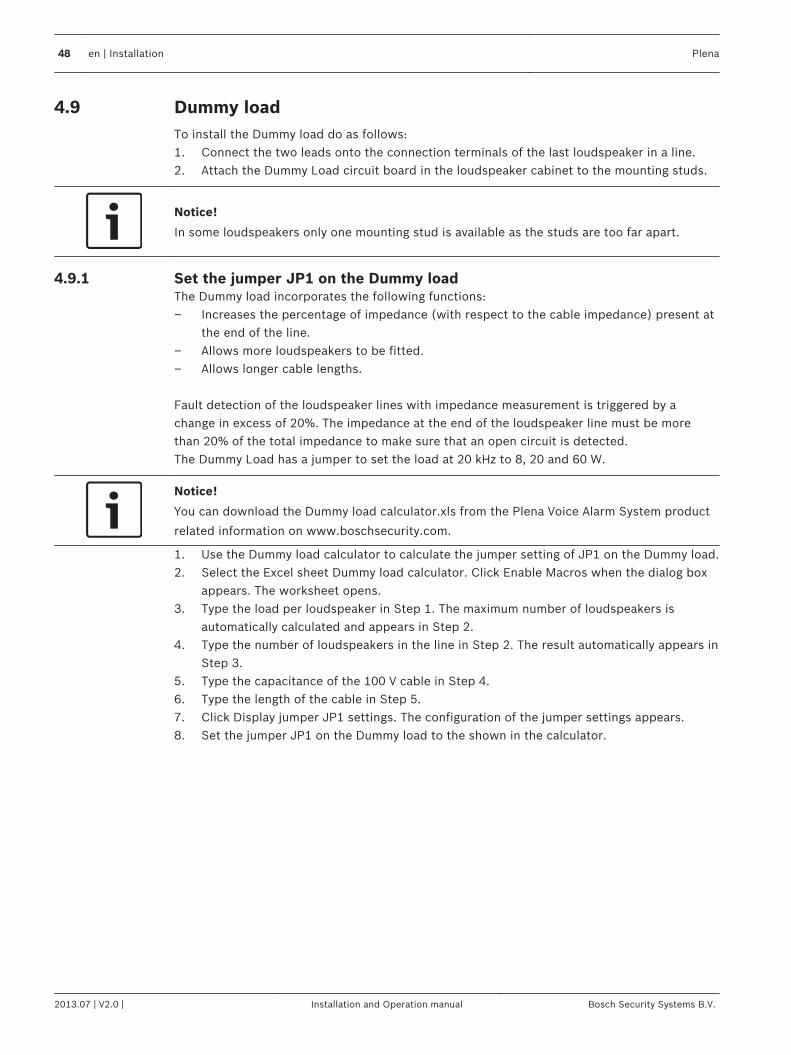
3. Connect a 20 or 22 kOhm resistor in parallel with the Trigger input to connect more thanone EOL board on a single Trigger input and to supervise them.
4. Connect the EOL boards to the Trigger input as indicated previousl. This input should beon the Controller or Router to which the loudspeaker lines it supervises are alsoconnected
Notice!
The last EOL board in line is connected in a different way than the other EOL boards. This is
required to supervise the whole EOL detection line against short circuit. Such a short circuit
will be reported as an Input Fault. A break in the detection line will be reported as a Line
Fault, just as a loudspeaker line failure.
4.8.1
4.8.2
46 en | Installation Plena
2013.07 | V2.0 | Installation and Operation manual Bosch Security Systems B.V.
JP1 JP1 JP1
Last EOL board First EOL board
20k
Figure 4.5: Trigger input indication
5. In the configuration program, set the Action Programming for the relevant input to Faultand EOL.
6. Enter the Zone or Zone group that is monitored by the EOL board. The Zone group can beAll Zones (of the Controller/Router), Zone 1‑3 or Zone 4‑6. Fault Type and Zone willdefine the visual indication on the unit in case of a fault.
7. Set the Action to Open and Type to Momentary.
Plena Installation | en 47
Bosch Security Systems B.V. Installation and Operation manual 2013.07 | V2.0 |
Dummy loadTo install the Dummy load do as follows:1. Connect the two leads onto the connection terminals of the last loudspeaker in a line.2. Attach the Dummy Load circuit board in the loudspeaker cabinet to the mounting studs.
Notice!
In some loudspeakers only one mounting stud is available as the studs are too far apart.
Set the jumper JP1 on the Dummy loadThe Dummy load incorporates the following functions:– Increases the percentage of impedance (with respect to the cable impedance) present at
the end of the line.– Allows more loudspeakers to be fitted.– Allows longer cable lengths. Fault detection of the loudspeaker lines with impedance measurement is triggered by achange in excess of 20%. The impedance at the end of the loudspeaker line must be morethan 20% of the total impedance to make sure that an open circuit is detected.The Dummy Load has a jumper to set the load at 20 kHz to 8, 20 and 60 W.
Notice!
You can download the Dummy load calculator.xls from the Plena Voice Alarm System product
related information on www.boschsecurity.com.
1. Use the Dummy load calculator to calculate the jumper setting of JP1 on the Dummy load.2. Select the Excel sheet Dummy load calculator. Click Enable Macros when the dialog box
appears. The worksheet opens.3. Type the load per loudspeaker in Step 1. The maximum number of loudspeakers is
automatically calculated and appears in Step 2.4. Type the number of loudspeakers in the line in Step 2. The result automatically appears in
Step 3.5. Type the capacitance of the 100 V cable in Step 4.6. Type the length of the cable in Step 5.7. Click Display jumper JP1 settings. The configuration of the jumper settings appears.8. Set the jumper JP1 on the Dummy load to the shown in the calculator.
4.9
4.9.1
48 en | Installation Plena
2013.07 | V2.0 | Installation and Operation manual Bosch Security Systems B.V.
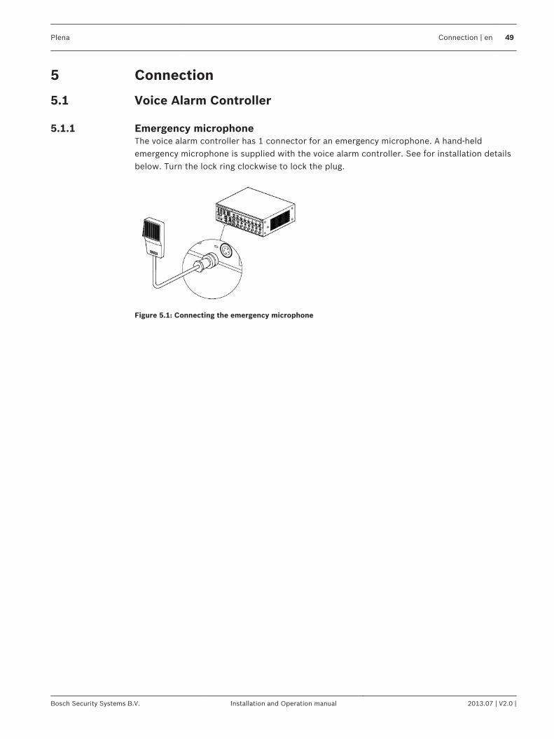
Connection
Voice Alarm Controller
Emergency microphoneThe voice alarm controller has 1 connector for an emergency microphone. A hand-heldemergency microphone is supplied with the voice alarm controller. See for installation detailsbelow. Turn the lock ring clockwise to lock the plug.
Figure 5.1: Connecting the emergency microphone
5
5.1
5.1.1
Plena Connection | en 49
Bosch Security Systems B.V. Installation and Operation manual 2013.07 | V2.0 |
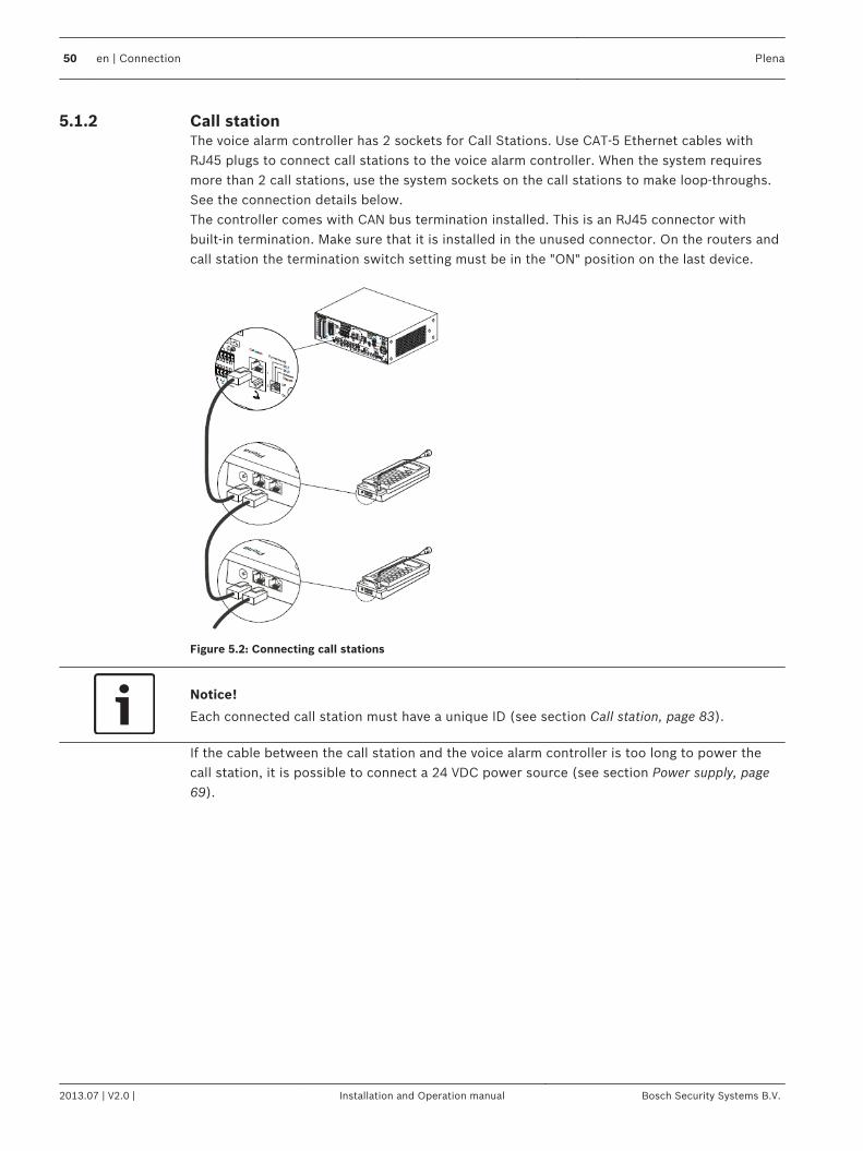
Call stationThe voice alarm controller has 2 sockets for Call Stations. Use CAT‑5 Ethernet cables withRJ45 plugs to connect call stations to the voice alarm controller. When the system requiresmore than 2 call stations, use the system sockets on the call stations to make loop-throughs.See the connection details below.The controller comes with CAN bus termination installed. This is an RJ45 connector withbuilt‑in termination. Make sure that it is installed in the unused connector. On the routers andcall station the termination switch setting must be in the "ON" position on the last device.
Figure 5.2: Connecting call stations
Notice!
Each connected call station must have a unique ID (see section Call station, page 83).
If the cable between the call station and the voice alarm controller is too long to power thecall station, it is possible to connect a 24 VDC power source (see section Power supply, page69).
5.1.2
50 en | Connection Plena
2013.07 | V2.0 | Installation and Operation manual Bosch Security Systems B.V.
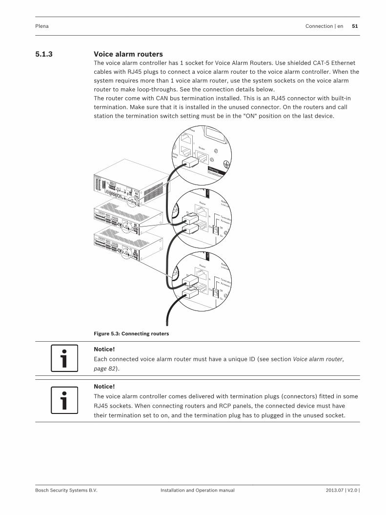
Voice alarm routersThe voice alarm controller has 1 socket for Voice Alarm Routers. Use shielded CAT‑5 Ethernetcables with RJ45 plugs to connect a voice alarm router to the voice alarm controller. When thesystem requires more than 1 voice alarm router, use the system sockets on the voice alarmrouter to make loop-throughs. See the connection details below.The router come with CAN bus termination installed. This is an RJ45 connector with built‑intermination. Make sure that it is installed in the unused connector. On the routers and callstation the termination switch setting must be in the "ON" position on the last device.
MonitoringSpeaker
ontrol Panel
Router
WarningThis apparatus must be earthed
1
2
Firmware upgrade
Design & QualityThe Netherlands
N663
Termination
1...9
ID
Router
Rated input powerLine fuse
Booster 2
In
Out
Mad
ein
Chin
a
On
Off
Firmware upgrade
Design & QualityThe Netherlands
N663
Termination
1...9
ID
Router
Rated input powerLine fuse
Booster 2
In
Out
Mad
ein
Chin
a
On
Off
Figure 5.3: Connecting routers
Notice!
Each connected voice alarm router must have a unique ID (see section Voice alarm router,
page 82).
Notice!
The voice alarm controller comes delivered with termination plugs (connectors) fitted in some
RJ45 sockets. When connecting routers and RCP panels, the connected device must have
their termination set to on, and the termination plug has to plugged in the unused socket.
5.1.3
Plena Connection | en 51
Bosch Security Systems B.V. Installation and Operation manual 2013.07 | V2.0 |
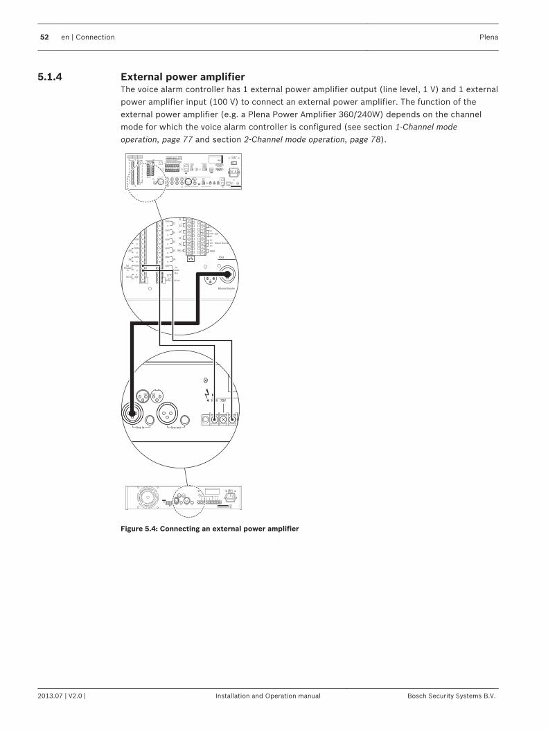
External power amplifierThe voice alarm controller has 1 external power amplifier output (line level, 1 V) and 1 externalpower amplifier input (100 V) to connect an external power amplifier. The function of theexternal power amplifier (e.g. a Plena Power Amplifier 360/240W) depends on the channelmode for which the voice alarm controller is configured (see section 1-Channel modeoperation, page 77 and section 2-Channel mode operation, page 78).
100V 70V 0 0
line in line out
1 2
3
1 2
3
GND GND+ +
- -
COM
NC
TRG2
Z2
Z3
Z4
Z5
Z6
Ext
Booster
In
DC In
0
TRG 1
Int
Booster
Out
24V
Fault
Call
External Booster
Out
100V
0
100V
0
100V
0
100V
0
100V
0
100V
0
24V
70V
Z2
Z3
Z4
Z5
Z6
GND
NC
COM
NO
NC
COM
NO
NO
100V
0
Call out
0
100V
0
100V
0
100V
0
100V
0
100V
0
Z2
Z3
Z4
Z5
Z6
NO
Volume Override
100V
Figure 5.4: Connecting an external power amplifier
5.1.4
52 en | Connection Plena
2013.07 | V2.0 | Installation and Operation manual Bosch Security Systems B.V.
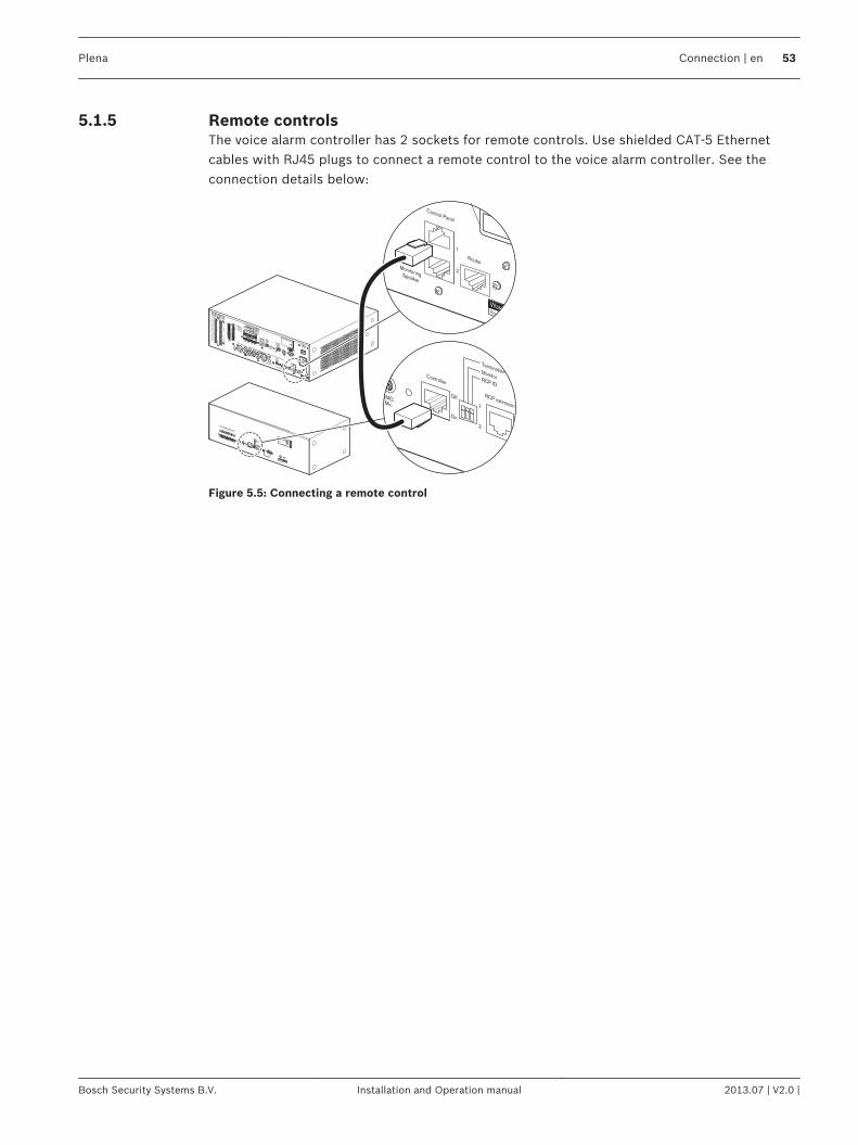
Remote controlsThe voice alarm controller has 2 sockets for remote controls. Use shielded CAT‑5 Ethernetcables with RJ45 plugs to connect a remote control to the voice alarm controller. See theconnection details below:
MonitoringSpeaker
Control Panel
Router
WarningThis apparatus must be earthed
1
2
Controller
Off
TerminationMonitorRCP ID
RCP extension
EMG.Mic
On
1
2
Design & QualityThe Netherlands
Plena Voice Alarm System
RC PanelMax. input power300mA, 24V DCS/N.
V6RC
A035413
63
Figure 5.5: Connecting a remote control
5.1.5
Plena Connection | en 53
Bosch Security Systems B.V. Installation and Operation manual 2013.07 | V2.0 |
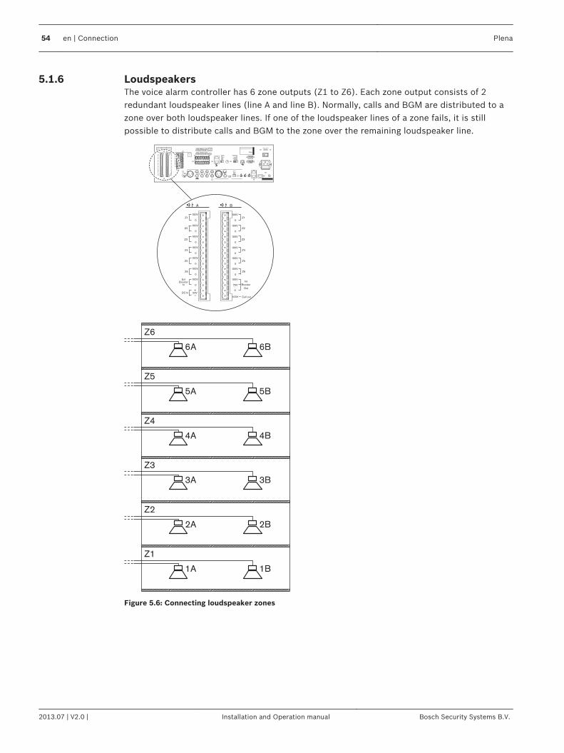
LoudspeakersThe voice alarm controller has 6 zone outputs (Z1 to Z6). Each zone output consists of 2redundant loudspeaker lines (line A and line B). Normally, calls and BGM are distributed to azone over both loudspeaker lines. If one of the loudspeaker lines of a zone fails, it is stillpossible to distribute calls and BGM to the zone over the remaining loudspeaker line.
Z1
Z2
Z3
Z4
Z5
Z6
Ext
Booster
In
DC In
100V
0
Int
Booster
Out
100V
0
100V
0
100V
0
100V
0
100V
0
100V
0
24V
70V
100V
0
Call out
100V
0
100V
0
100V
0
100V
0
100V
0
100V
0
Z2
Z3
Z4
Z5
Z6
Z1
A B
Int B BGM/
100V
1A 1B
2A 2B
3A 3B
4A 4B
5A 5B
6A
Z6
Z5
Z4
Z3
Z2
Z1
6B
Figure 5.6: Connecting loudspeaker zones
5.1.6
54 en | Connection Plena
2013.07 | V2.0 | Installation and Operation manual Bosch Security Systems B.V.
If it is necessary to detect the removal or failure of a single loudspeaker, the following isadvised:– Do not connect more than 5 loudspeakers to the same loudspeaker line (line A or line B).
Field tests have shown that the impedance of loudspeakers and loudspeaker lines varieswith temperature and age. The limit of 5 loudspeakers is set due to this variation. In amore stable environment, the number of loudspeakers can be higher.
– Make sure that all loudspeakers connected to the same loudspeaker line have the sameimpedance.
Notice!
The impedance measurement of the Plena Voice Alarm System has an accuracy better than
2%. The system only generates a fault if the line impedance difference is greater than the
configured accuracy. Use the configuration software to configure the accuracy
Notice!
See the Configuration Software Manual for more information about the configuration
software.
Notice!
The maximum load for the internal power amplifier of the voice alarm controller is 240 W.
However, if the voice alarm controller is used in 2‑channel mode and an external 480 W
amplifier is connected to it, the maximum loudspeaker load can be 480 W at 100 V. This is
because in 2‑channel mode, the internal power amplifier of the voice alarm controller is used
for BGM only and distributes BGM at ‑3 dB, from which follows that the maximum power
output is 240 W at 70 V and that the loading caused by 100 V loudspeakers at 70 V is also
240 W. The external amplifier is used for calls only with 480 W output power and 100 V
loudspeaker line voltage.
Notice!
The voice alarm system has great flexibility, from one amplifier for all routers to one amplifier
per router, or any arrangement in between. But in a 2‑channel system, the number and type
of amplifiers for the call-channel has to be exactly mirrored for the music channel. Getting the
signal from the same routers and feeding loudspeaker signal to the same set of routers. If not,
amplifier supervision and amplifier sparing will not function properly.
Plena Connection | en 55
Bosch Security Systems B.V. Installation and Operation manual 2013.07 | V2.0 |
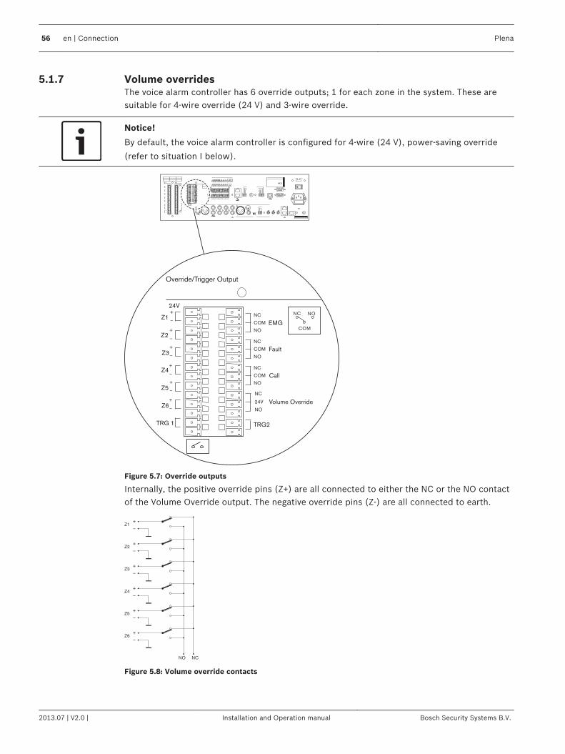
Volume overridesThe voice alarm controller has 6 override outputs; 1 for each zone in the system. These aresuitable for 4‑wire override (24 V) and 3‑wire override.
Notice!
By default, the voice alarm controller is configured for 4‑wire (24 V), power-saving override
(refer to situation I below).
COM
NC NO
NC
TRG2
Override/Trigger Output
TRG 1
24V
EMG
Fault
Call
Z1
Z2
Z3
Z4
Z5
Z6
NC
COM
NO
NC
COM
NO
NC
COM
NO
NO
24V
Volume Override
Figure 5.7: Override outputs
Internally, the positive override pins (Z+) are all connected to either the NC or the NO contactof the Volume Override output. The negative override pins (Z-) are all connected to earth.
Z1+
_
Z2+
_
Z3+
_
Z4+
_
Z5+
_
Z6+
_
NO NC
Figure 5.8: Volume override contacts
5.1.7
56 en | Connection Plena
2013.07 | V2.0 | Installation and Operation manual Bosch Security Systems B.V.
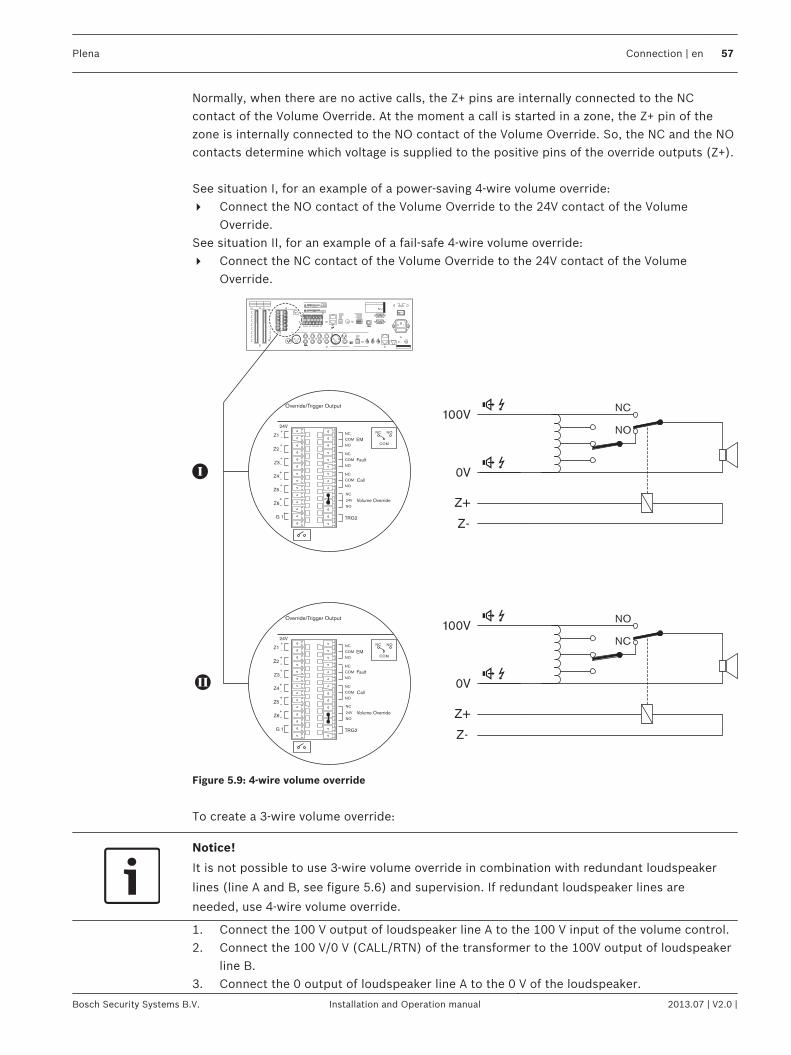
Normally, when there are no active calls, the Z+ pins are internally connected to the NCcontact of the Volume Override. At the moment a call is started in a zone, the Z+ pin of thezone is internally connected to the NO contact of the Volume Override. So, the NC and the NOcontacts determine which voltage is supplied to the positive pins of the override outputs (Z+). See situation I, for an example of a power-saving 4-wire volume override:4 Connect the NO contact of the Volume Override to the 24V contact of the Volume
Override.See situation II, for an example of a fail-safe 4-wire volume override:4 Connect the NC contact of the Volume Override to the 24V contact of the Volume
Override.
COM
NC NO
NC
TRG2
Override/Trigger Output
G 1
24V
EM
Fault
Call
Z1
Z2
Z3
Z4
Z5
Z6
NC
COM
NO
NC
COM
NO
NC
COM
NO
NO
24V
Volume Override
100V
0V
Z+
Z-
NO
NC
COM
NC NO
NC
TRG2
Override/Trigger Output
G 1
24V
EM
Fault
Call
Z1
Z2
Z3
Z4
Z5
Z6
NC
COM
NO
NC
COM
NO
NC
COM
NO
NO
24V
Volume Override
100V
0V
Z+
Z-
NC
NO
Figure 5.9: 4‑wire volume override
To create a 3‑wire volume override:
Notice!
It is not possible to use 3‑wire volume override in combination with redundant loudspeaker
lines (line A and B, see figure 5.6) and supervision. If redundant loudspeaker lines are
needed, use 4‑wire volume override.
1. Connect the 100 V output of loudspeaker line A to the 100 V input of the volume control.2. Connect the 100 V/0 V (CALL/RTN) of the transformer to the 100V output of loudspeaker
line B.3. Connect the 0 output of loudspeaker line A to the 0 V of the loudspeaker.
Plena Connection | en 57
Bosch Security Systems B.V. Installation and Operation manual 2013.07 | V2.0 |
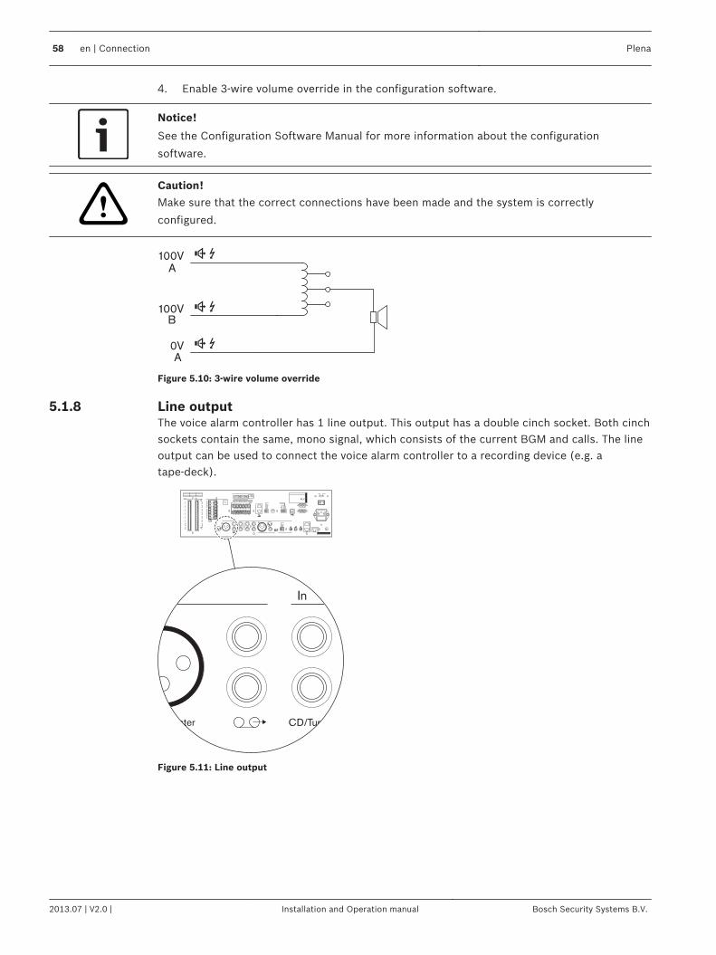
4. Enable 3‑wire volume override in the configuration software.
Notice!
See the Configuration Software Manual for more information about the configuration
software.
!
Caution!
Make sure that the correct connections have been made and the system is correctly
configured.
100V
A
A
B
100V
0V
Figure 5.10: 3‑wire volume override
Line outputThe voice alarm controller has 1 line output. This output has a double cinch socket. Both cinchsockets contain the same, mono signal, which consists of the current BGM and calls. The lineoutput can be used to connect the voice alarm controller to a recording device (e.g. atape‑deck).
In
ternal Booster CD/Tuner
Figure 5.11: Line output
5.1.8
58 en | Connection Plena
2013.07 | V2.0 | Installation and Operation manual Bosch Security Systems B.V.
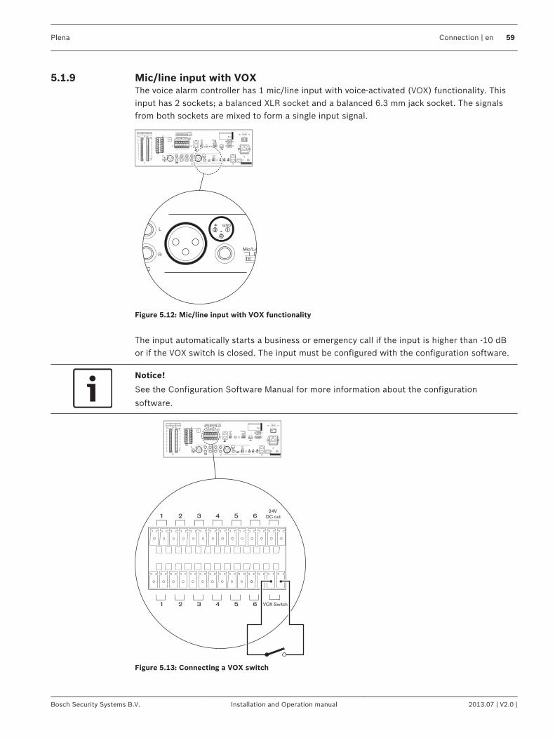
Mic/line input with VOXThe voice alarm controller has 1 mic/line input with voice-activated (VOX) functionality. Thisinput has 2 sockets; a balanced XLR socket and a balanced 6.3 mm jack socket. The signalsfrom both sockets are mixed to form a single input signal.
L
R
PC
ImpedanceCalibration
Mic/Line
GND
Figure 5.12: Mic/line input with VOX functionality
The input automatically starts a business or emergency call if the input is higher than -10 dBor if the VOX switch is closed. The input must be configured with the configuration software.
Notice!
See the Configuration Software Manual for more information about the configuration
software.
1 2 3 4 5 6
VOX Switch1 2 3 4 5 6
24V
DC out
Figure 5.13: Connecting a VOX switch
5.1.9
Plena Connection | en 59
Bosch Security Systems B.V. Installation and Operation manual 2013.07 | V2.0 |
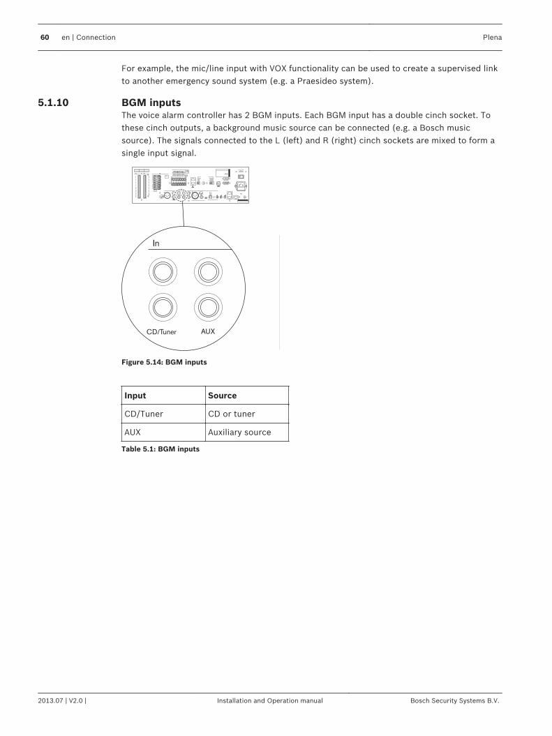
For example, the mic/line input with VOX functionality can be used to create a supervised linkto another emergency sound system (e.g. a Praesideo system).
BGM inputsThe voice alarm controller has 2 BGM inputs. Each BGM input has a double cinch socket. Tothese cinch outputs, a background music source can be connected (e.g. a Bosch musicsource). The signals connected to the L (left) and R (right) cinch sockets are mixed to form asingle input signal.
AUX
In
CD/Tuner
Figure 5.14: BGM inputs
Input Source
CD/Tuner CD or tuner
AUX Auxiliary source
Table 5.1: BGM inputs
5.1.10
60 en | Connection Plena
2013.07 | V2.0 | Installation and Operation manual Bosch Security Systems B.V.
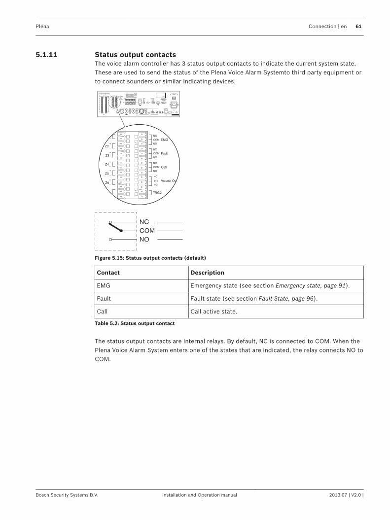
Status output contactsThe voice alarm controller has 3 status output contacts to indicate the current system state.These are used to send the status of the Plena Voice Alarm Systemto third party equipment orto connect sounders or similar indicating devices.
NC
TRG2TR
24V
EMG
Fault
Call
Z1
Z2
Z3
Z4
Z5
Z6
NC
COM
NO
NC
COM
NO
NC
COM
NO
NO
V
NC
COM
NO
olume Override
Figure 5.15: Status output contacts (default)
Contact Description
EMG Emergency state (see section Emergency state, page 91).
Fault Fault state (see section Fault State, page 96).
Call Call active state.
Table 5.2: Status output contact
The status output contacts are internal relays. By default, NC is connected to COM. When thePlena Voice Alarm System enters one of the states that are indicated, the relay connects NO toCOM.
5.1.11
Plena Connection | en 61
Bosch Security Systems B.V. Installation and Operation manual 2013.07 | V2.0 |

PowerIntroductionThe voice alarm controller has the following power connections:– Mains power connection.– Back-up power connection.
Mains powerProceed as follows to connect the voice alarm controller to the mains power:4 Select the local mains voltage using the voltage selector on the rear of the voice alarm
controller.
115V~ 230V~
Apparatus deliveredConnected for 230V~
Power
Figure 5.16: Voltage selector
Selector Mains voltage V(AC) Fuse
115 100 - 120 115 V - 10 AT
230 220 - 240 230 V - 6,3 AT
Table 5.3: Voltage selector
Notice!
The Voice Alarm Controller is delivered with the voltage selector in the 230 V position.
1. Put the correct type of fuse in the voice alarm controller.
Notice!
The Voice Alarm Controller is delivered with a T6.3L 250 V fuse for a mains voltage of
220 to 240 V(AC).
2. Connect a locally approved mains cord to the voice alarm controller.3. Connect the mains cord to a locally approved mains outlet.
5.1.12
62 en | Connection Plena
2013.07 | V2.0 | Installation and Operation manual Bosch Security Systems B.V.
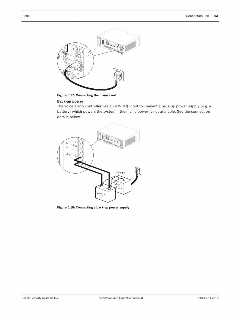
COM
NCNO
10k10k
Trigger input/24V DC out
Business
Emergency
NC
TRG2
Override/Trigger Output
AUX
L
R
PC
DigitalMessageMonitoringSpeaker
Remote Control Panel
ImpedanceCalibration
In
Voice Alarm Controller
Max. output power 360W
Rated output power 240W
115-230V~, 50/60Hz
S/N.
Design & QualityThe Netherlands
N663
Phantom power
Z1
Z2
Z3
Z4
Z5
Z6
ExtBoosterIn
DC In
100V
0
TRG 1
IntBooster
Out
24V
EMG
Fault
Call
External Booster
Out
CD/Tuner
SEL1SEL0FirmwareUpgrade
MonitorAPR modeSupervision2ch operationLBB1994
Off
On
USB
VoxSpeech filter
Mic/Line
Vox
LBB1994
Rated input power:760VALine fuseT6.3L250V for230V AC
T10L250V for115V AC
115V~230V~
Apparatus deliveredConnected for 230V~
Power
Router
WarningThis apparatus must be earthed
100V
0
100V
0
100V
0
100V
0
100V
0
100V
0
24V
70V
Z1
Z2
Z3
Z4
Z5
Z6
GND
Fireman's panel
1 2 3 4 5 6
1 2 3 4 5 61 2 3 4 5 6
Off
On
Off
On
Call stationFor service only
GND
24VDC out
VOXSwitch
VOX Switch
1 2 3 4 5 6
NC
COMNO
NC
COMNO
NC
COMNO
100V
0
Call out
100V
0
100V
0
100V
0
100V
0
100V
0
100V
0
Z2
Z3
Z4
Z5
Z6
Z1
A
B
NO
24VDC out
24V
1 Channel2 Channel
Int BoosterExt Booster
BGM/Spare
N.C./Spare
Call
BGM/Call
Volume Override
100V
1
2
1
2
DigitalMessageMonitoringSpeaker
Remote Control Panel
90/00 8900 199 00001
Plena Voice Alarm Controller
Max. output power 360W
Rated output power 240W
5-230V~, 50/60Hz
S/N.
Design & QualityThe Netherlands
N663
Phantom power
USB
LBB1994
Rated input power:760VALine fuseT6.3L250V for230V AC
T10L250V for115V AC
115V~230V~
Apparatus deliveredConnected for 230V~
Power
Router
W
Fireman's panel
1
2
Figure 5.17: Connecting the mains cord
Back-up powerThe voice alarm controller has a 24 V(DC) input to connect a back-up power supply (e.g. abattery) which powers the system if the mains power is not available. See the connectiondetails below:
COM
NCNO
10k10k
Trigger input/24V DC out
Business
Emergency
NC
TRG2
Override/Trigger Output
AUX
L
R
PC
DigitalMessageMonitoringSpeaker
Remote Control Panel
ImpedanceCalibration
In
Voice Alarm Controller
Max. output power 360W
Rated output power 240W
115-230V~, 50/60Hz
S/N.
Design & QualityThe Netherlands
N663
Phantom power
Z1
Z2
Z3
Z4
Z5
Z6
ExtBoosterIn
DC In
100V
0
TRG 1
IntBooster
Out
24V
EMG
Fault
Call
External Booster
Out
CD/Tuner
SEL1SEL0FirmwareUpgrade
MonitorAPR modeSupervision2ch operationLBB1994
Off
On
USB
VoxSpeech filter
Mic/Line
Vox
LBB1994
Rated input power:760VALine fuseT6.3L250V for230V AC
T10L250V for115V AC
115V~230V~
Apparatus deliveredConnected for 230V~
Power
Router
WarningThis apparatus must be earthed
100V
0
100V
0
100V
0
100V
0
100V
0
100V
0
24V
70V
Z1
Z2
Z3
Z4
Z5
Z6
GND
Fireman's panel
1 2 3 4 5 6
1 2 3 4 5 61 2 3 4 5 6
Off
On
Off
On
Call stationFor service only
GND
24VDC out
VOXSwitch
VOX Switch
1 2 3 4 5 6
NC
COMNO
NC
COMNO
NC
COMNO
100V
0
Call out
100V
0
100V
0
100V
0
100V
0
100V
0
100V
0
Z2
Z3
Z4
Z5
Z6
Z1
A
B
NO
24VDC out
24V
1 Channel2 Channel
Int BoosterExt Booster
BGM/Spare
N.C./Spare
Call
BGM/Call
Volume Override
100V
1
2
1
2
Z6
Ext
In
DC In
100V
0
24V
100V
0
Charger
24 VDC
-+
Figure 5.18: Connecting a back-up power supply
Plena Connection | en 63
Bosch Security Systems B.V. Installation and Operation manual 2013.07 | V2.0 |
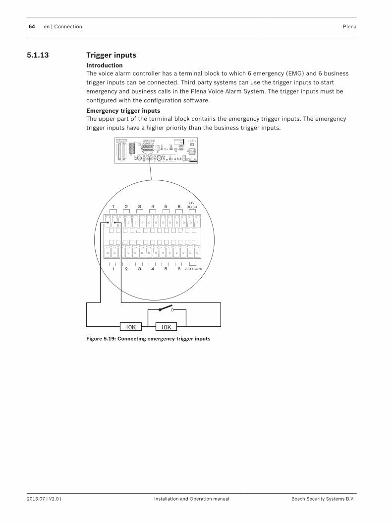
Trigger inputsIntroductionThe voice alarm controller has a terminal block to which 6 emergency (EMG) and 6 businesstrigger inputs can be connected. Third party systems can use the trigger inputs to startemergency and business calls in the Plena Voice Alarm System. The trigger inputs must beconfigured with the configuration software.
Emergency trigger inputsThe upper part of the terminal block contains the emergency trigger inputs. The emergencytrigger inputs have a higher priority than the business trigger inputs.
1 2 3 4 5 6
VOX Switch1 2 3 4 5 6
24V
DC out
10K 10K
Figure 5.19: Connecting emergency trigger inputs
5.1.13
64 en | Connection Plena
2013.07 | V2.0 | Installation and Operation manual Bosch Security Systems B.V.
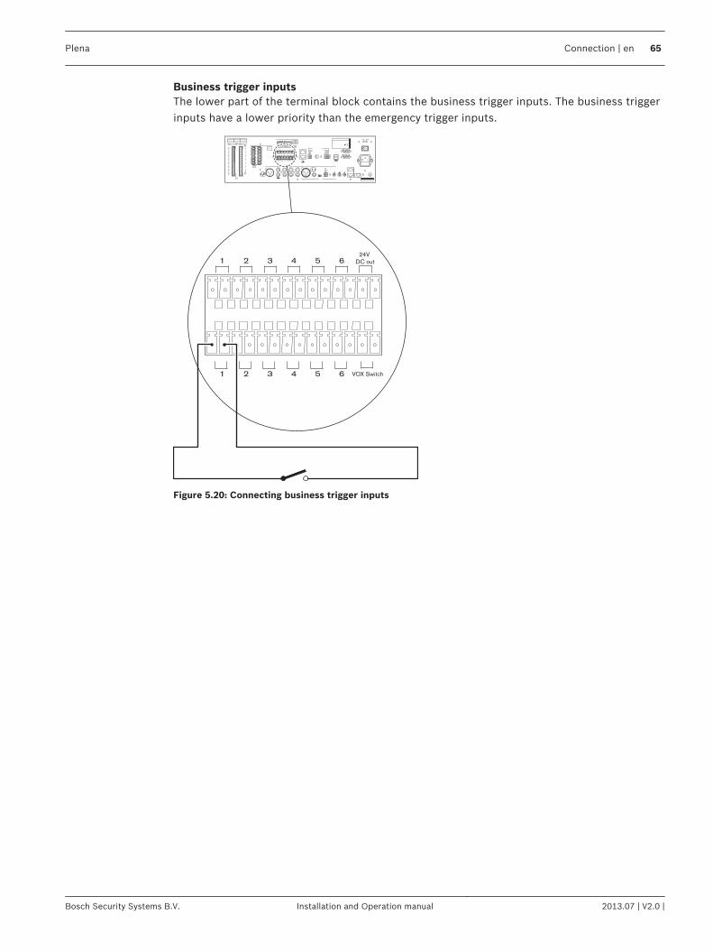
Business trigger inputsThe lower part of the terminal block contains the business trigger inputs. The business triggerinputs have a lower priority than the emergency trigger inputs.
1 2 3 4 5 6
VOX Switch1 2 3 4 5 6
24V
DC out
Figure 5.20: Connecting business trigger inputs
Plena Connection | en 65
Bosch Security Systems B.V. Installation and Operation manual 2013.07 | V2.0 |
Voice Alarm Router
Voice alarm controllerConnect the voice alarm router to the voice alarm controller (see section Voice alarm routers,page 51).
LoudspeakersThe voice alarm router has 6 zone outputs (Z1 to Z6). The procedure for connectingloudspeakers to a voice alarm router is the same as the procedure for connectingloudspeakers to a voice alarm controller (see section Loudspeakers, page 54).
Volume overridesThe voice alarm router has 6 override outputs; 1 for each connected zone. These are suitablefor 4‑wire override (24 V) and for 3‑wire override. The procedure for using volume override inzones that are connected to a voice alarm router is the same as the procedure for usingvolume override in zones that are connected to the voice alarm controller (see section Volumeoverrides, page 56).
Trigger inputsThe voice alarm router has a terminal block to which 6 emergency (EMG) and 6 businesstrigger inputs can be connected. Third party systems can use the trigger inputs to startemergency and business calls in the Plena Voice Alarm System. The trigger inputs must beconfigured with the configuration software. The procedure for connecting trigger inputs to avoice alarm router is similar to the procedure for connecting trigger inputs to the voice alarmcontroller (see section Trigger inputs, page 64).
5.2
5.2.1
5.2.2
5.2.3
5.2.4
66 en | Connection Plena
2013.07 | V2.0 | Installation and Operation manual Bosch Security Systems B.V.
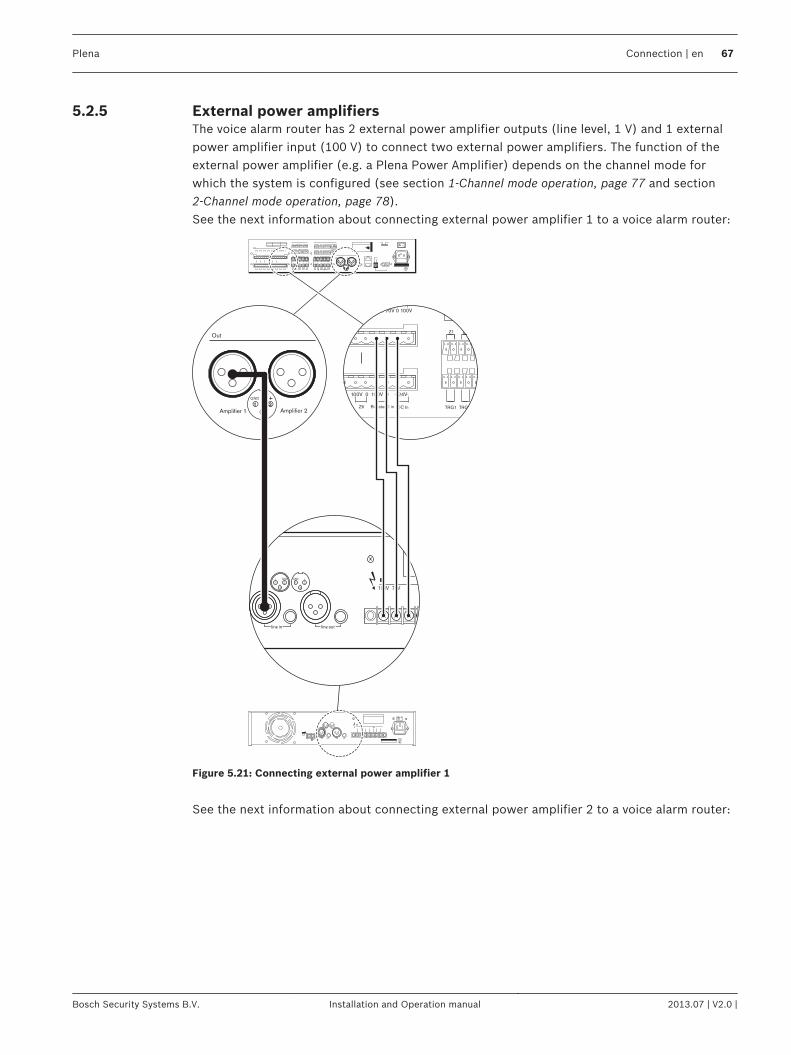
External power amplifiersThe voice alarm router has 2 external power amplifier outputs (line level, 1 V) and 1 externalpower amplifier input (100 V) to connect two external power amplifiers. The function of theexternal power amplifier (e.g. a Plena Power Amplifier) depends on the channel mode forwhich the system is configured (see section 1-Channel mode operation, page 77 and section2-Channel mode operation, page 78).See the next information about connecting external power amplifier 1 to a voice alarm router:
Design & QualityThe Netherlands
Amplifier 1
Out
GND
Amplifier 2
100V 70V 0 0
line in line out
1 2
3
1 2
3
GND GND+ +
- -
0V 0 100V 0 100V 70V 0 100V
TRG1 TRG2
NC
BFailure
0V 0 100V 0 100V 0 +24V-
Booster 2 inZ5 Z6 DC In
Z1 Z2 Z3
Figure 5.21: Connecting external power amplifier 1
See the next information about connecting external power amplifier 2 to a voice alarm router:
5.2.5
Plena Connection | en 67
Bosch Security Systems B.V. Installation and Operation manual 2013.07 | V2.0 |
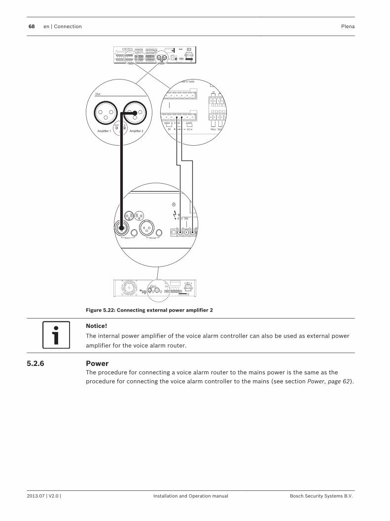
Design & QualityThe Netherlands
Out
GND
Amplifier 1 Amplifier 2
100V 70V 0 0
line in line out
1 2
3
1 2
3
GND GND+ +
- -
0V 0 100V 0 100V 70V 0 100V
TRG1 TRG2
NC
BFailure
0V 0 100V 0 100V 0 +24V-
Booster 2 inZ5 Z6 DC In
Z1 Z2 Z3
Figure 5.22: Connecting external power amplifier 2
Notice!
The internal power amplifier of the voice alarm controller can also be used as external power
amplifier for the voice alarm router.
PowerThe procedure for connecting a voice alarm router to the mains power is the same as theprocedure for connecting the voice alarm controller to the mains (see section Power, page 62).
5.2.6
68 en | Connection Plena
2013.07 | V2.0 | Installation and Operation manual Bosch Security Systems B.V.
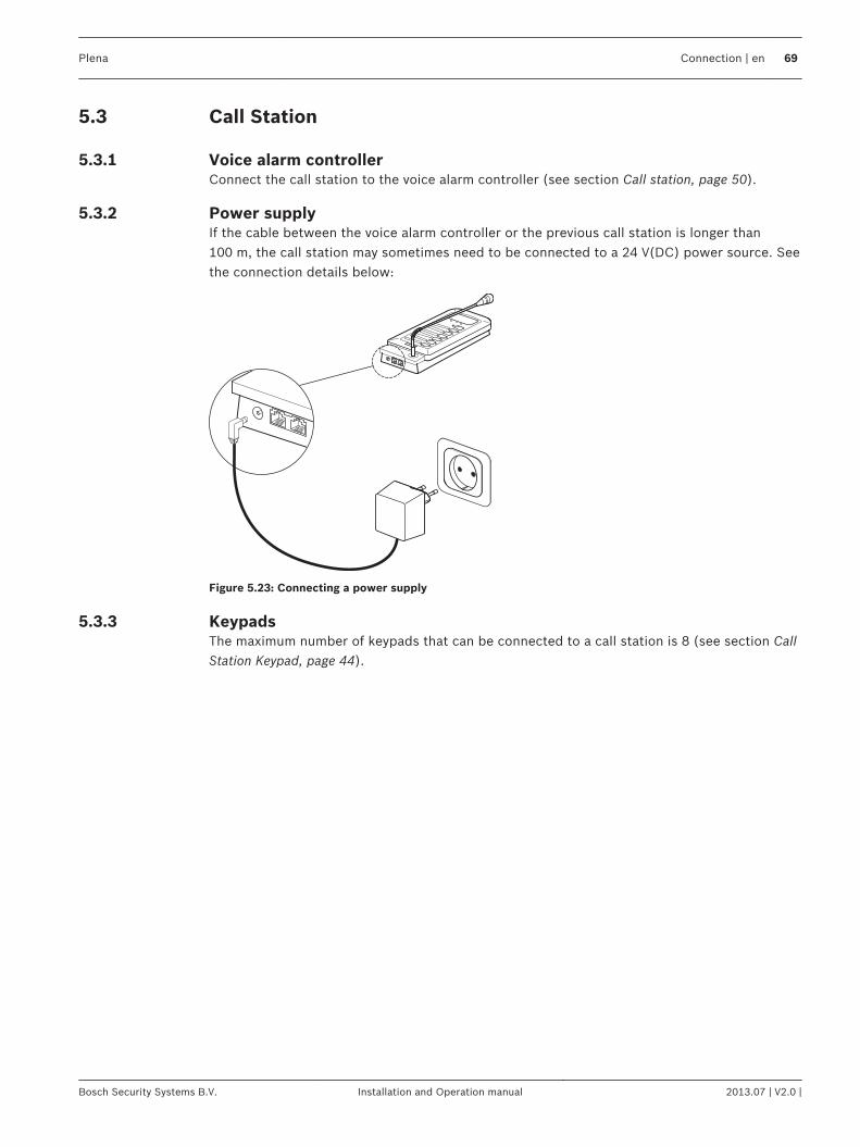
Call Station
Voice alarm controllerConnect the call station to the voice alarm controller (see section Call station, page 50).
Power supplyIf the cable between the voice alarm controller or the previous call station is longer than100 m, the call station may sometimes need to be connected to a 24 V(DC) power source. Seethe connection details below:
Figure 5.23: Connecting a power supply
KeypadsThe maximum number of keypads that can be connected to a call station is 8 (see section CallStation Keypad, page 44).
5.3
5.3.1
5.3.2
5.3.3
Plena Connection | en 69
Bosch Security Systems B.V. Installation and Operation manual 2013.07 | V2.0 |
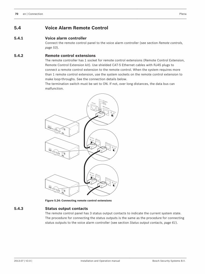
Voice Alarm Remote Control
Voice alarm controllerConnect the remote control panel to the voice alarm controller (see section Remote controls,page 53).
Remote control extensionsThe remote controller has 1 socket for remote control extensions (Remote Control Extension,Remote Control Extension kit). Use shielded CAT‑5 Ethernet cables with RJ45 plugs toconnect a remote control extension to the remote control. When the system requires morethan 1 remote control extension, use the system sockets on the remote control extension tomake loop‑throughs. See the connection details below.The termination switch must be set to ON. If not, over long distances, the data bus canmalfunction.
RCP ext. In
RCP ext. Out
Off On
Termination
For service onlyOffOn
RCP ext. In
RCP ext. Out
Off On
Termination
For service onlyOffOn
6
1...9
ID
12
34
5 7
98 RCP ext. In
RCP ext. Out
Off On
Termination
FirmwareUpgrade
For service onlyOffOn
WarningThis apparatus must be earthed
Trigger Output
Power
24VDC In
32
1
Fault
Design & QualityThe Netherlands
RC Panel ExtensionMax. input power200mA, 24V DCS/N.
A035413
N663
NC
NOC
OM
6
1...9
ID
12
34
5 7
98 RCP ext. In
RCP ext. Out
Off On
Termination
FirmwareUpgrade
For service onlyOffOn
WarningThis apparatus must be earthed
Trigger Output
Power
24VDC In
32
1
Fault
Design & QualityThe Netherlands
RC Panel ExtensionMax. input power200mA, 24V DCS/N.
A035413
N663
NC
NOC
OM
Design & QualityThe Netherlands
RC PanelMax. input power300mA, 24V DCS/N.
PLN-V6RC
A035413
N663
Figure 5.24: Connecting remote control extensions
Status output contactsThe remote control panel has 3 status output contacts to indicate the current system state.The procedure for connecting the status outputs is the same as the procedure for connectingstatus outputs to the voice alarm controller (see section Status output contacts, page 61).
5.4
5.4.1
5.4.2
5.4.3
70 en | Connection Plena
2013.07 | V2.0 | Installation and Operation manual Bosch Security Systems B.V.
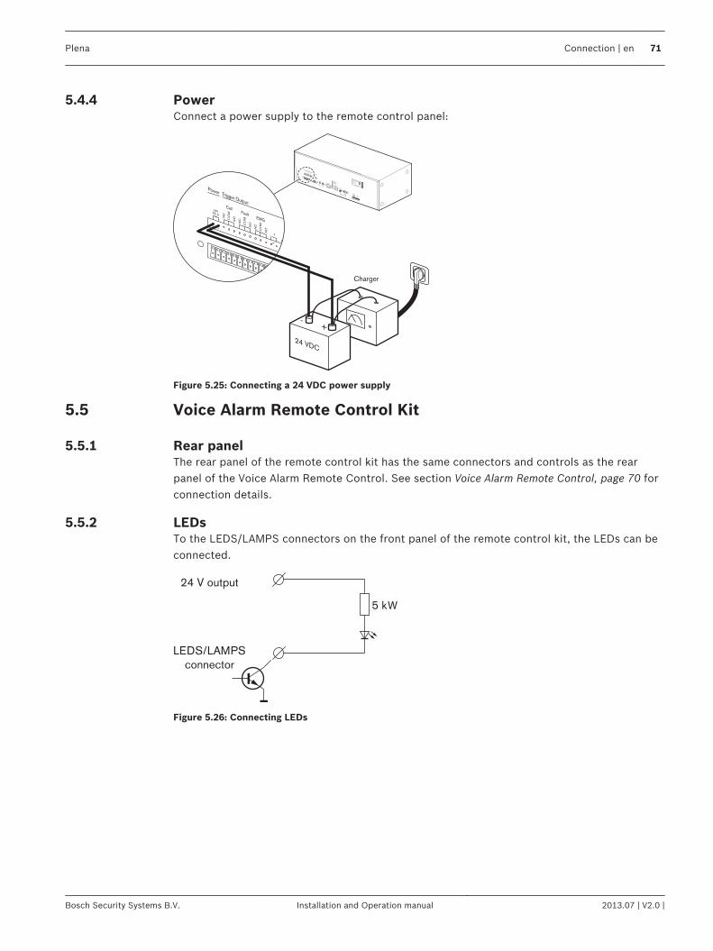
PowerConnect a power supply to the remote control panel:
Design & Quality
The Netherlands
RC PanelMax. input power300mA, 24V DCS/N.
A035413
N663
Charger
24 VDC
-+
Figure 5.25: Connecting a 24 VDC power supply
Voice Alarm Remote Control Kit
Rear panelThe rear panel of the remote control kit has the same connectors and controls as the rearpanel of the Voice Alarm Remote Control. See section Voice Alarm Remote Control, page 70 forconnection details.
LEDsTo the LEDS/LAMPS connectors on the front panel of the remote control kit, the LEDs can beconnected.
24 V output
5 k
LEDS/LAMPS
connector
W
Figure 5.26: Connecting LEDs
5.4.4
5.5
5.5.1
5.5.2
Plena Connection | en 71
Bosch Security Systems B.V. Installation and Operation manual 2013.07 | V2.0 |
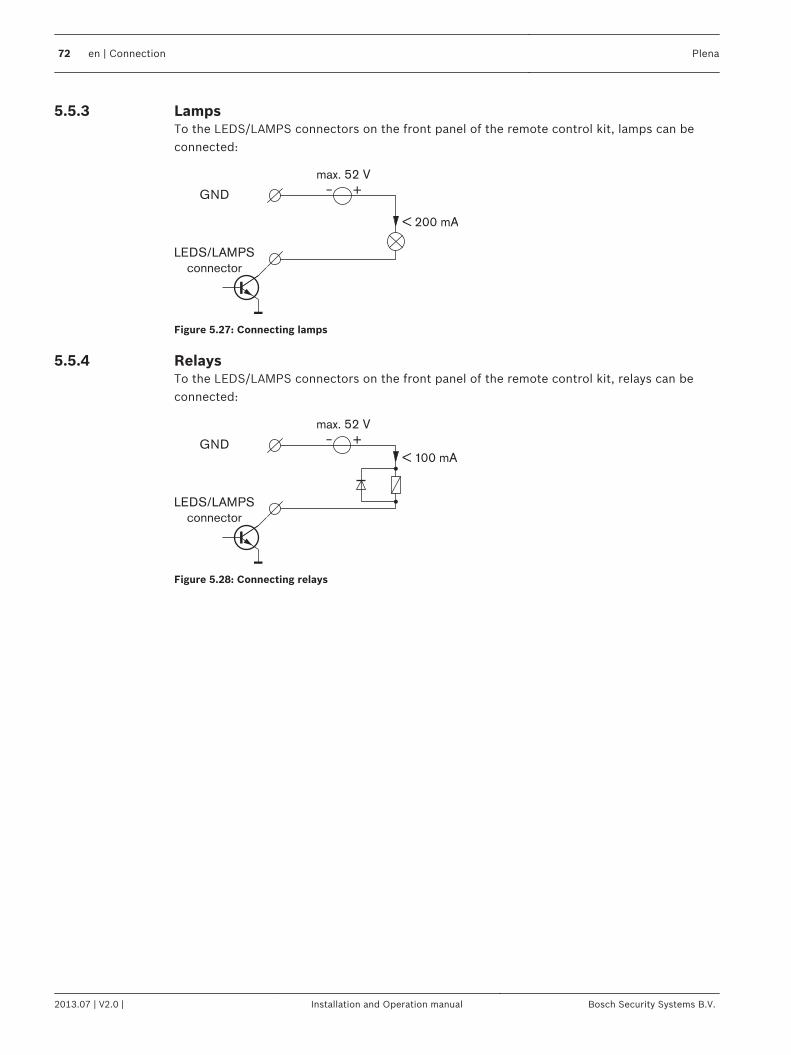
LampsTo the LEDS/LAMPS connectors on the front panel of the remote control kit, lamps can beconnected:
GND
max. 52 V
LEDS/LAMPS
connector
< 200 mA
Figure 5.27: Connecting lamps
RelaysTo the LEDS/LAMPS connectors on the front panel of the remote control kit, relays can beconnected:
GND
max. 52 V
LEDS/LAMPS
connector
< 100 mA
Figure 5.28: Connecting relays
5.5.3
5.5.4
72 en | Connection Plena
2013.07 | V2.0 | Installation and Operation manual Bosch Security Systems B.V.
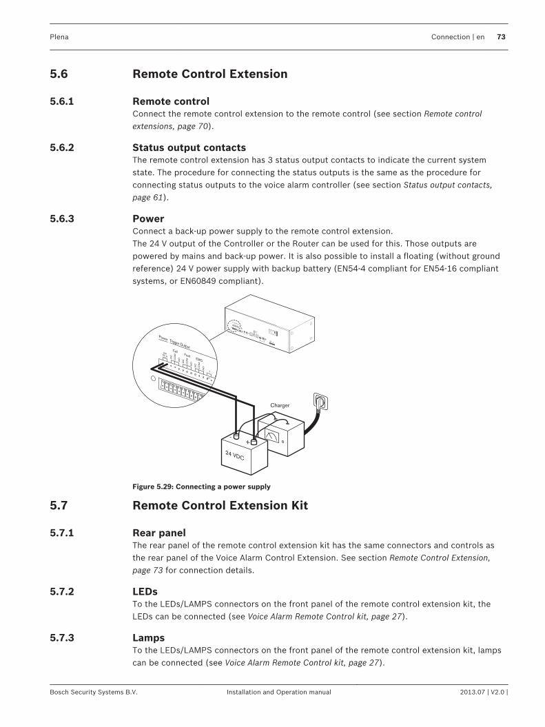
Remote Control Extension
Remote controlConnect the remote control extension to the remote control (see section Remote controlextensions, page 70).
Status output contactsThe remote control extension has 3 status output contacts to indicate the current systemstate. The procedure for connecting the status outputs is the same as the procedure forconnecting status outputs to the voice alarm controller (see section Status output contacts,page 61).
PowerConnect a back‑up power supply to the remote control extension.The 24 V output of the Controller or the Router can be used for this. Those outputs arepowered by mains and back‑up power. It is also possible to install a floating (without groundreference) 24 V power supply with backup battery (EN54‑4 compliant for EN54‑16 compliantsystems, or EN60849 compliant).
Design & Quality
The Netherlands
RC PanelMax. input power300mA, 24V DCS/N.
A035413
N663
Charger
24 VDC
-+
Figure 5.29: Connecting a power supply
Remote Control Extension Kit
Rear panelThe rear panel of the remote control extension kit has the same connectors and controls asthe rear panel of the Voice Alarm Control Extension. See section Remote Control Extension,page 73 for connection details.
LEDsTo the LEDs/LAMPS connectors on the front panel of the remote control extension kit, theLEDs can be connected (see Voice Alarm Remote Control kit, page 27).
LampsTo the LEDs/LAMPS connectors on the front panel of the remote control extension kit, lampscan be connected (see Voice Alarm Remote Control kit, page 27).
5.6
5.6.1
5.6.2
5.6.3
5.7
5.7.1
5.7.2
5.7.3
Plena Connection | en 73
Bosch Security Systems B.V. Installation and Operation manual 2013.07 | V2.0 |
RelaysTo the LEDs/LAMPS connectors on the front panel of the remote control extension kit, relayscan be connected (see Voice Alarm Remote Control kit, page 27).
Fireman’s Panel
Voice alarm controllerConnect the fireman’s panel to the voice alarm controller (see section Remote controls, page53).
Remote control extensionsThe fireman’s panel has 1 socket for remote control extensions (Remote Control Extension,Remote Control Extension kit). Use shielded CAT‑5 Ethernet cables with RJ45 plugs toconnect a remote control extension to the fireman’s panel. When the system requires morethan 1 remote control extension, use the system sockets on the remote control extension tomake loop‑throughs. See section Remote control extensions, page 70 for connection details.
Status output contactsThe fireman’s panel has 3 status output contacts to indicate the current system state. Theprocedure for connecting the status outputs is the same as the procedure for connectingstatus outputs to the voice alarm controller (see section Status output contacts, page 61).
PowerThe procedure for connecting a fireman’s panel to a power supply is the same as theprocedure for connecting a remote control to a power supply (see section Power, page 71).
5.7.4
5.8
5.8.1
5.8.2
5.8.3
5.8.4
74 en | Connection Plena
2013.07 | V2.0 | Installation and Operation manual Bosch Security Systems B.V.
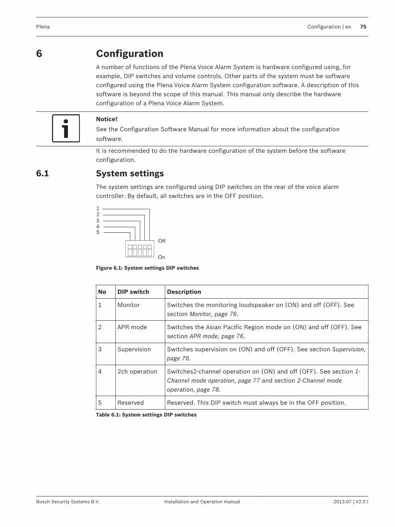
ConfigurationA number of functions of the Plena Voice Alarm System is hardware configured using, forexample, DIP switches and volume controls. Other parts of the system must be softwareconfigured using the Plena Voice Alarm System configuration software. A description of thissoftware is beyond the scope of this manual. This manual only describe the hardwareconfiguration of a Plena Voice Alarm System.
Notice!
See the Configuration Software Manual for more information about the configuration
software.
It is recommended to do the hardware configuration of the system before the softwareconfiguration.
System settingsThe system settings are configured using DIP switches on the rear of the voice alarmcontroller. By default, all switches are in the OFF position.
1
2
3
4
5
Off
On
Figure 6.1: System settings DIP switches
No DIP switch Description
1 Monitor Switches the monitoring loudspeaker on (ON) and off (OFF). Seesection Monitor, page 76.
2 APR mode Switches the Asian Pacific Region mode on (ON) and off (OFF). Seesection APR mode, page 76.
3 Supervision Switches supervision on (ON) and off (OFF). See section Supervision,page 76.
4 2ch operation Switches2-channel operation on (ON) and off (OFF). See section 1-Channel mode operation, page 77 and section 2-Channel modeoperation, page 78.
5 Reserved Reserved. This DIP switch must always be in the OFF position.
Table 6.1: System settings DIP switches
6
6.1
Plena Configuration | en 75
Bosch Security Systems B.V. Installation and Operation manual 2013.07 | V2.0 |
MonitorIf the Monitor switch is in the ON position, the internal monitoring loudspeaker of the voicealarm controller is switched on. The volume of the monitoring loudspeaker is set with theMonitoring Speaker volume control (see Controls, connectors and indicators, page 14, no. 36).
APR modeIf the APR mode switch is in the ON position, the system is in the Asian-Pacific Region (APR)mode. In APR mode, the system operates according to the emergency standards of the Asian-Pacific Region. In the APR mode:– The priority level of the emergency trigger inputs is always 14.– Emergency and business trigger inputs of the same zone form pairs. The settings of the
emergency trigger input (software configurable) apply to both.– The emergency trigger inputs are never supervised.– When an emergency trigger input is activated, the system enters the emergency state.
The voice alarm controller also automatically starts a pre-emergency announcement andalarm message (software configurable).
– When a business trigger input is activated, the system enters the emergency state. Thevoice alarm controller does not automatically start a pre‑emergency announcement andalarm message.
– The red LED, which during normal operation indicates that the zone is selected for anemergency call (see Controls, connectors and indicators, page 14, no. 5), indicates that anemergency trigger input is active.
– The green LED, which during normal operation indicates that a business call is running inthe zone (see Controls, connectors and indicators, page 14, no. 5), indicates that anemergency call is running in the zone.
– The priority level of the emergency microphone of the voice alarm controller is always 16.– When the emergency button (see Controls, connectors and indicators, page 14, no. 12) is
pushed on the front of the voice alarm controller, an alarm message is automaticallystarted. This message is automatically repeated.
SupervisionIf the Supervision switch (see System settings, page 75) is in the ON position, supervision isenabled. If it is in the OFF position, supervision is disabled. See section Supervision, page 78for more information about supervision.
6.1.1
6.1.2
6.1.3
76 en | Configuration Plena
2013.07 | V2.0 | Installation and Operation manual Bosch Security Systems B.V.
1-Channel mode operationIf the 2ch operation switch (see 2-Channel mode operation, page 78) is in the OFF position,the system operates in the 1‑channel mode.
Voice alarm controllerIn the 1‑channel mode, all calls and BGM are amplified by the internal power amplifier of thevoice alarm controller. If desired, an external power amplifier can be connected for spareswitching (see section External power amplifier, page 52). In 1‑channel mode, all calls willinterrupt the BGM.
Amplifier Function
Internal BGM/Call power amplifier.
External Not connected/Spare power amplifier.
Table 6.2: 1-channel mode, voice alarm controller
Voice alarm routerOne or two external power amplifiers can be connected to a voice alarm router to increase thepower of the system (see section External power amplifiers, page 67). In 1‑channel mode:– External power amplifier 1 of the voice alarm router is used to increase the power for
calls and BGM, that go via the internal power amplifier of the voice alarm controller.– External power amplifier 2 of the voice alarm router is used for spare-switching.
Amplifier Function
1 BGM/Call power amplifier.
2 Not connected/Spare power amplifier.
Table 6.3: 1-channel mode, voice alarm router
6.1.4
Plena Configuration | en 77
Bosch Security Systems B.V. Installation and Operation manual 2013.07 | V2.0 |

2-Channel mode operationIf the 2ch operation switch (see System settings, page 75) is in the ON position, the systemoperates in the 2‑channel mode.
Voice alarm controllerIn the 2‑channel mode, the BGM is amplified by the internal power amplifier of the voice alarmcontroller. The calls are amplified by the external power amplifier, which is connected to thevoice alarm controller (see section External power amplifier, page 52). If the external poweramplifier is faulty, the calls are amplified by the internal power amplifier. In 2‑channel mode,calls do not interrupt the BGM.
Amplifier Function
Internal BGM/Spare power amplifier.
External Call power amplifier.
Table 6.4: 2-channel mode, controller
Voice alarm routerOne or two external power amplifiers can be connected to a voice alarm router to increase thepower of the system (see section External power amplifiers, page 67). In 2‑channel mode:– External power amplifier 1 of the voice alarm router is used to increase the power of the
internal power amplifier of the voice alarm controller.– External power amplifier 2 of the voice alarm router is used to help the external power
amplifier of the voice alarm controller to amplify calls.
Amplifier Function
1 BGM/Spare power amplifier.
2 Call power amplifier.
Table 6.5: 2-channel mode, router
SupervisionIf the Supervision switch (see System settings, page 75) is in the ON position, supervision isenabled. If it is in the OFF position, supervision is disabled.
Notice!
Supervision is only necessary for systems that have to comply to the IEC60849 evacuation
standard. If the system does not have to comply to this standard, leave the switch in the OFF
position.
If the Supervision switch is in the OFF position, the Disabled indicator on the front panel ofthe voice alarm controller is lit to indicate that supervision is switched off.
Processor reset
Network
Call/EMG
Music/Spare
Ground short
Input
Mains
Battery
Zone1
Zone2
Zone3
Zone4
Zone5
Zone6
Fault IndicatorsA B
Disabled
Message
EMG mic
RCP
Router
0 dB
-6dB
-20dB
Figure 6.2: Disabled indicator
If the Supervision switch is in the ON position, an indicator is lit when a supervised functionfails (see section Fault State, page 96). Use the configuration software to switch supervisedfunctions on and off.
6.1.5
6.2
78 en | Configuration Plena
2013.07 | V2.0 | Installation and Operation manual Bosch Security Systems B.V.
Notice!
See the Configuration Software Manual for more information about the configuration
software.
Processor resetWatchdogIf supervision is enabled (see section Supervision, page 78), the processor of the voice alarmcontroller is supervised by a watchdog. If the watchdog triggers, the Processor reset indicatoron the front panel of the voice alarm controller is lit. Then, the program memory is checkedand the processor resumes operation within 10 seconds. The indicator remains on until thefault is acknowledged and reset.
New firmwareA processor reset sometimes happens after new firmware is installed. make sure the ServiceDIP switches are put back to the correct position. The correct positions are:– SEL0 and SEL1 to ON.– Enable Firmware Download to OFF.
NetworkIf supervision is enabled and network supervision is switched on (see section Supervision,page 78), the connections from the voice alarm controller to the voice alarm routers andremote controls are supervised. When any voice alarm router or remote control is missingduring a network check, a network error is reported.
Power amplifiersIf supervision is enabled and call power amplifier supervision is switched on (see sectionSupervision, page 78), the call power amplifiers in the system are supervised. In theconfiguration software, mark the checkbox Call/EMG to enable this function.If supervision is enabled and BGM/Spare power amplifier supervision is switched on (seesection Supervision, page 78), the BGM and spare power amplifiers in the system aresupervised. In the configuration software, mark the checkbox Spare to enable this function.
Ground shortIf supervision is enabled and ground short supervision is switched on (see section Supervision,page 78), the system can continuously monitor loudspeaker lines in the system for short-to-ground situations. For each loudspeaker line, short-to-ground supervision can be switched onand off with the configuration software.
Notice!
See the Configuration Software Manual for more information about the configuration
software.
If a leakage current > 30 + 15 mA is detected in a line, the line is considered faulty.
6.2.1
6.2.2
6.2.3
6.2.4
Plena Configuration | en 79
Bosch Security Systems B.V. Installation and Operation manual 2013.07 | V2.0 |
Emergency trigger inputsIf supervision is enabled and input supervision is switched on (see section Supervision, page78), the system can supervise the emergency trigger inputs. For each emergency trigger input,supervision can be switched on and off with the configuration software.
Notice!
See the Configuration Software Manual for more information about the configuration
software.
Mains powerIf supervision is enabled and mains power supervision is switched on (see section Supervision,page 78), the availability of the mains power is supervised.
BatteryIf supervision is enabled and battery supervision is switched on (see section Supervision, page78), the availability of the back-up power is supervised.
Message supervisionIf supervision is enabled and message supervision is switched on (see section Supervision,page 78), the internal message manager of the voice alarm controller is supervised. Thismessage supervision consists of supervision of the wave player using a check‑sum andsupervision of the audio path using a pilot‑tone.
Emergency microphoneIf supervision is enabled and emergency microphone supervision is switched on (see sectionSupervision, page 78), the audio path and the PTT switch of the emergency microphone aremonitored from the capsule to the connection with the voice alarm controller.
Line supervisionIf supervision is enabled and line supervision (see section Supervision, page 78) is switchedon, all loudspeaker lines are supervised. Line supervision consists of:– Impedance supervision.– Short‑to‑ground supervision.
Impedance supervisionIf line supervision is switched on, the voice alarm controller measures the impedance of allloudspeaker lines once every 90 seconds (default value). The reference values for impedancesupervision are stored in the voice alarm controller during the system calibration (see sectionCalibration, page 87). If a difference of > 15% (default value) is detected between themeasured line impedance and its reference value, the line is considered faulty. The defaultvalues can be changed with the configuration software.
Notice!
A small click can be heard at the start and end of an impedance measurement. If the click is
unacceptable, then end of line supervision with EOL can be considered instead of impedance
supervision.
Notice!
See the Configuration Software Manual for more information about the configuration
software.
6.2.5
6.2.6
6.2.7
6.2.8
6.2.9
6.2.10
80 en | Configuration Plena
2013.07 | V2.0 | Installation and Operation manual Bosch Security Systems B.V.
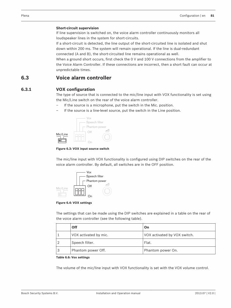
Short-circuit supervisionIf line supervision is switched on, the voice alarm controller continuously monitors allloudspeaker lines in the system for short-circuits.If a short‑circuit is detected, the line output of the short-circuited line is isolated and shutdown within 200 ms. The system will remain operational. If the line is dual-redundantconnected (A and B), the short-circuited line remains operational as well.When a ground short occurs, first check the 0 V and 100 V connections from the amplifier tothe Voice Alarm Controller. If these connections are incorrect, then a short fault can occur atunpredictable times.
Voice alarm controller
VOX configurationThe type of source that is connected to the mic/line input with VOX functionality is set usingthe Mic/Line switch on the rear of the voice alarm controller.– If the source is a microphone, put the switch in the Mic. position.– If the source is a line-level source, put the switch in the Line position.
Phantom power
Vox
Speech filter
Off
On
Mic/Line
Figure 6.3: VOX input source switch
The mic/line input with VOX functionality is configured using DIP switches on the rear of thevoice alarm controller. By default, all switches are in the OFF position.
Phantom power
Vox
Speech filter
Off
On
Mic/Line
Figure 6.4: VOX settings
The settings that can be made using the DIP switches are explained in a table on the rear ofthe voice alarm controller (see the following table).
Off On
1 VOX activated by mic. VOX activated by VOX switch.
2 Speech filter. Flat.
3 Phantom power Off. Phantom power On.
Table 6.6: Vox settings
The volume of the mic/line input with VOX functionality is set with the VOX volume control.
6.3
6.3.1
Plena Configuration | en 81
Bosch Security Systems B.V. Installation and Operation manual 2013.07 | V2.0 |
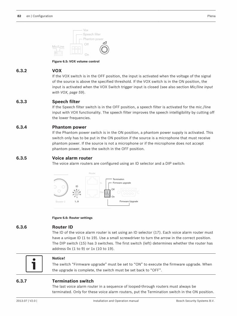
Phantom power
Vox
Speech filter
Off
On
Mic/Line
Figure 6.5: VOX volume control
VOXIf the VOX switch is in the OFF position, the input is activated when the voltage of the signalof the source is above the specified threshold. If the VOX switch is in the ON position, theinput is activated when the VOX Switch trigger input is closed (see also section Mic/line inputwith VOX, page 59).
Speech filterIf the Speech filter switch is in the OFF position, a speech filter is activated for the mic./lineinput with VOX functionality. The speech filter improves the speech intelligibility by cutting offthe lower frequencies.
Phantom powerIf the Phantom power switch is in the ON position, a phantom power supply is activated. Thisswitch only has to be put in the ON position if the source is a microphone that must receivephantom power. If the source is not a microphone or if the microphone does not acceptphantom power, leave the switch in the OFF position.
Voice alarm routerThe voice alarm routers are configured using an ID selector and a DIP switch:
Booster 1
Out
1...9
ID
Router
GND
Booster 2
In
Out
Firmware upgrade
Firmware Upgrade
Termination
Off
On
Figure 6.6: Router settings
Router IDThe ID of the voice alarm router is set using an ID selector (17). Each voice alarm router musthave a unique ID (1 to 19). Use a small screwdriver to turn the arrow in the correct position.The DIP switch (15) has 3 switches. The first switch (left) determines whether the router hasaddress 0x (1 to 9) or 1x (10 to 19).
Notice!
The switch “Firmware upgrade” must be set to “ON” to execute the firmware upgrade. When
the upgrade is complete, the switch must be set back to “OFF”.
Termination switchThe last voice alarm router in a sequence of looped-through routers must always beterminated. Only for these voice alarm routers, put the Termination switch in the ON position.
6.3.2
6.3.3
6.3.4
6.3.5
6.3.6
6.3.7
82 en | Configuration Plena
2013.07 | V2.0 | Installation and Operation manual Bosch Security Systems B.V.
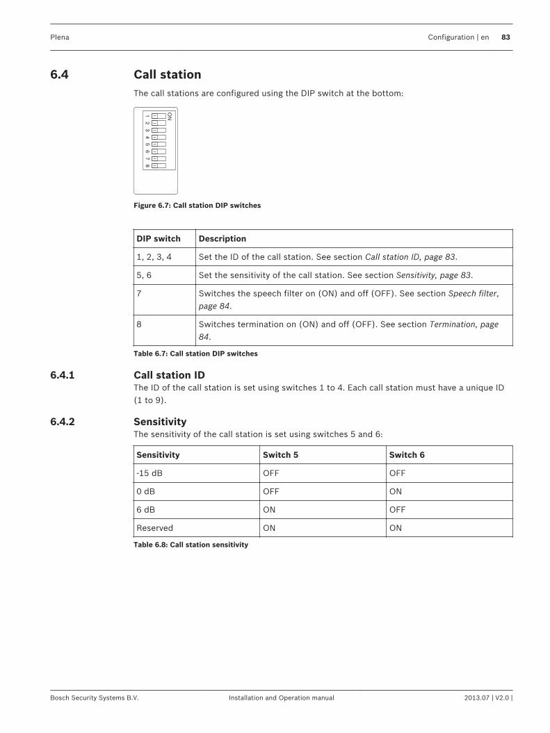
Call stationThe call stations are configured using the DIP switch at the bottom:
ON
12
34
56
78
Figure 6.7: Call station DIP switches
DIP switch Description
1, 2, 3, 4 Set the ID of the call station. See section Call station ID, page 83.
5, 6 Set the sensitivity of the call station. See section Sensitivity, page 83.
7 Switches the speech filter on (ON) and off (OFF). See section Speech filter,page 84.
8 Switches termination on (ON) and off (OFF). See section Termination, page84.
Table 6.7: Call station DIP switches
Call station IDThe ID of the call station is set using switches 1 to 4. Each call station must have a unique ID(1 to 9).
SensitivityThe sensitivity of the call station is set using switches 5 and 6:
Sensitivity Switch 5 Switch 6
-15 dB OFF OFF
0 dB OFF ON
6 dB ON OFF
Reserved ON ON
Table 6.8: Call station sensitivity
6.4
6.4.1
6.4.2
Plena Configuration | en 83
Bosch Security Systems B.V. Installation and Operation manual 2013.07 | V2.0 |
Speech filterIf switch 7 is in the ON position, a speech filter is activated for the call station. The speechfilter improves the speech intelligibility by cutting off the lower frequencies.
TerminationThe last call station in a sequence of looped-through call stations must always be terminated.Only for these call stations, put switch 8 in the ON position.
Notice!
The Controller comes with a termination plug (RJ45). Plug this connector in the unused RJ45
socket.
6.4.3
6.4.4
84 en | Configuration Plena
2013.07 | V2.0 | Installation and Operation manual Bosch Security Systems B.V.
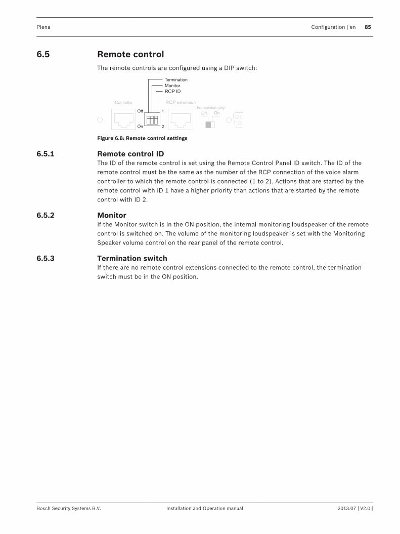
Remote controlThe remote controls are configured using a DIP switch:
Figure 6.8: Remote control settings
Remote control IDThe ID of the remote control is set using the Remote Control Panel ID switch. The ID of theremote control must be the same as the number of the RCP connection of the voice alarmcontroller to which the remote control is connected (1 to 2). Actions that are started by theremote control with ID 1 have a higher priority than actions that are started by the remotecontrol with ID 2.
MonitorIf the Monitor switch is in the ON position, the internal monitoring loudspeaker of the remotecontrol is switched on. The volume of the monitoring loudspeaker is set with the MonitoringSpeaker volume control on the rear panel of the remote control.
Termination switchIf there are no remote control extensions connected to the remote control, the terminationswitch must be in the ON position.
6.5
6.5.1
6.5.2
6.5.3
Plena Configuration | en 85
Bosch Security Systems B.V. Installation and Operation manual 2013.07 | V2.0 |
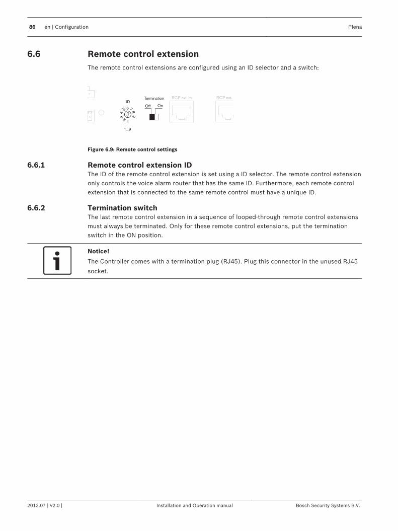
Remote control extensionThe remote control extensions are configured using an ID selector and a switch:
6
1...9
ID
12
34
5 7
98
RCP ext. In RCP ext. Out
Off On
Termination
3
Figure 6.9: Remote control settings
Remote control extension IDThe ID of the remote control extension is set using a ID selector. The remote control extensiononly controls the voice alarm router that has the same ID. Furthermore, each remote controlextension that is connected to the same remote control must have a unique ID.
Termination switchThe last remote control extension in a sequence of looped-through remote control extensionsmust always be terminated. Only for these remote control extensions, put the terminationswitch in the ON position.
Notice!
The Controller comes with a termination plug (RJ45). Plug this connector in the unused RJ45
socket.
6.6
6.6.1
6.6.2
86 en | Configuration Plena
2013.07 | V2.0 | Installation and Operation manual Bosch Security Systems B.V.
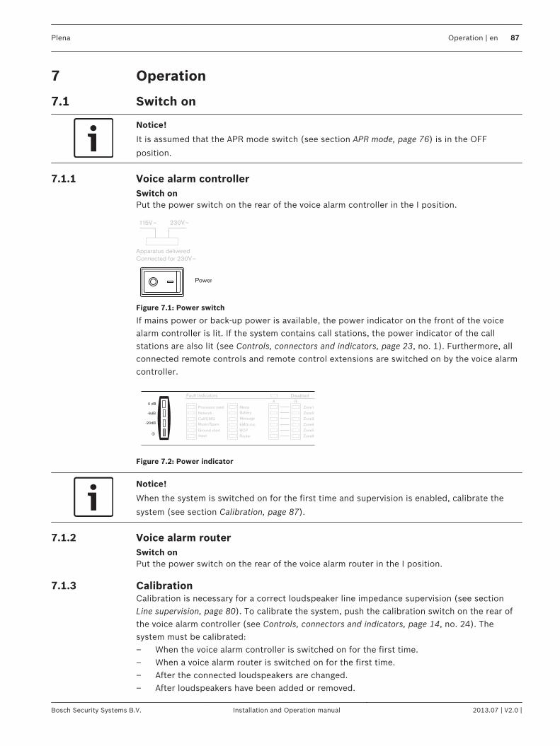
Operation
Switch on
Notice!
It is assumed that the APR mode switch (see section APR mode, page 76) is in the OFF
position.
Voice alarm controllerSwitch onPut the power switch on the rear of the voice alarm controller in the I position.
115V~ 230V~
Apparatus deliveredConnected for 230V~
Power
Figure 7.1: Power switch
If mains power or back‑up power is available, the power indicator on the front of the voicealarm controller is lit. If the system contains call stations, the power indicator of the callstations are also lit (see Controls, connectors and indicators, page 23, no. 1). Furthermore, allconnected remote controls and remote control extensions are switched on by the voice alarmcontroller.
Processor reset
Network
Call/EMG
Music/Spare
Ground short
Input
Mains
Battery
Zone1
Zone2
Zone3
Zone4
Zone5
Zone6
Fault IndicatorsA B
Disabled
Message
EMG mic
RCP
Router
0 dB
-6dB
-20dB
Figure 7.2: Power indicator
Notice!
When the system is switched on for the first time and supervision is enabled, calibrate the
system (see section Calibration, page 87).
Voice alarm routerSwitch onPut the power switch on the rear of the voice alarm router in the I position.
CalibrationCalibration is necessary for a correct loudspeaker line impedance supervision (see sectionLine supervision, page 80). To calibrate the system, push the calibration switch on the rear ofthe voice alarm controller (see Controls, connectors and indicators, page 14, no. 24). Thesystem must be calibrated:– When the voice alarm controller is switched on for the first time.– When a voice alarm router is switched on for the first time.– After the connected loudspeakers are changed.– After loudspeakers have been added or removed.
7
7.1
7.1.1
7.1.2
7.1.3
Plena Operation | en 87
Bosch Security Systems B.V. Installation and Operation manual 2013.07 | V2.0 |
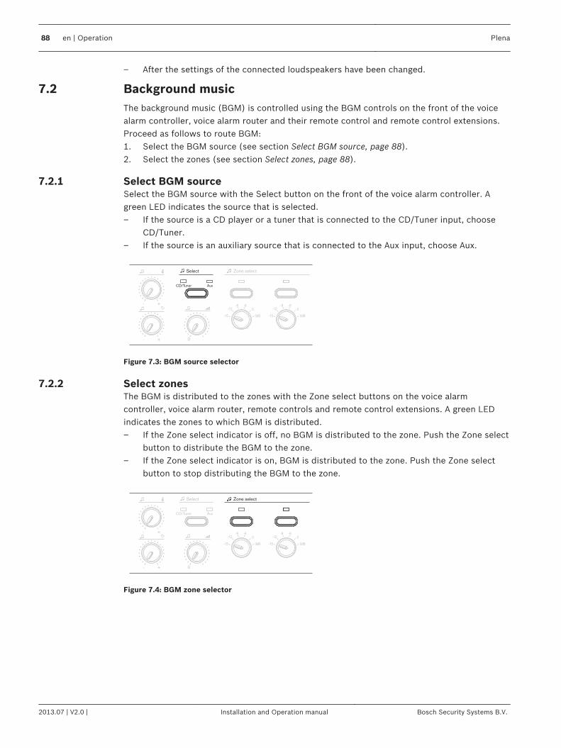
– After the settings of the connected loudspeakers have been changed.
Background musicThe background music (BGM) is controlled using the BGM controls on the front of the voicealarm controller, voice alarm router and their remote control and remote control extensions.Proceed as follows to route BGM:1. Select the BGM source (see section Select BGM source, page 88).2. Select the zones (see section Select zones, page 88).
Select BGM sourceSelect the BGM source with the Select button on the front of the voice alarm controller. Agreen LED indicates the source that is selected.– If the source is a CD player or a tuner that is connected to the CD/Tuner input, choose
CD/Tuner.– If the source is an auxiliary source that is connected to the Aux input, choose Aux.
0- +
- +
CD/Tuner Aux
Select Zone select
Figure 7.3: BGM source selector
Select zonesThe BGM is distributed to the zones with the Zone select buttons on the voice alarmcontroller, voice alarm router, remote controls and remote control extensions. A green LEDindicates the zones to which BGM is distributed.– If the Zone select indicator is off, no BGM is distributed to the zone. Push the Zone select
button to distribute the BGM to the zone.– If the Zone select indicator is on, BGM is distributed to the zone. Push the Zone select
button to stop distributing the BGM to the zone.
Zone select
0- +
- +
CD/Tuner Aux
Select
Figure 7.4: BGM zone selector
7.2
7.2.1
7.2.2
88 en | Operation Plena
2013.07 | V2.0 | Installation and Operation manual Bosch Security Systems B.V.
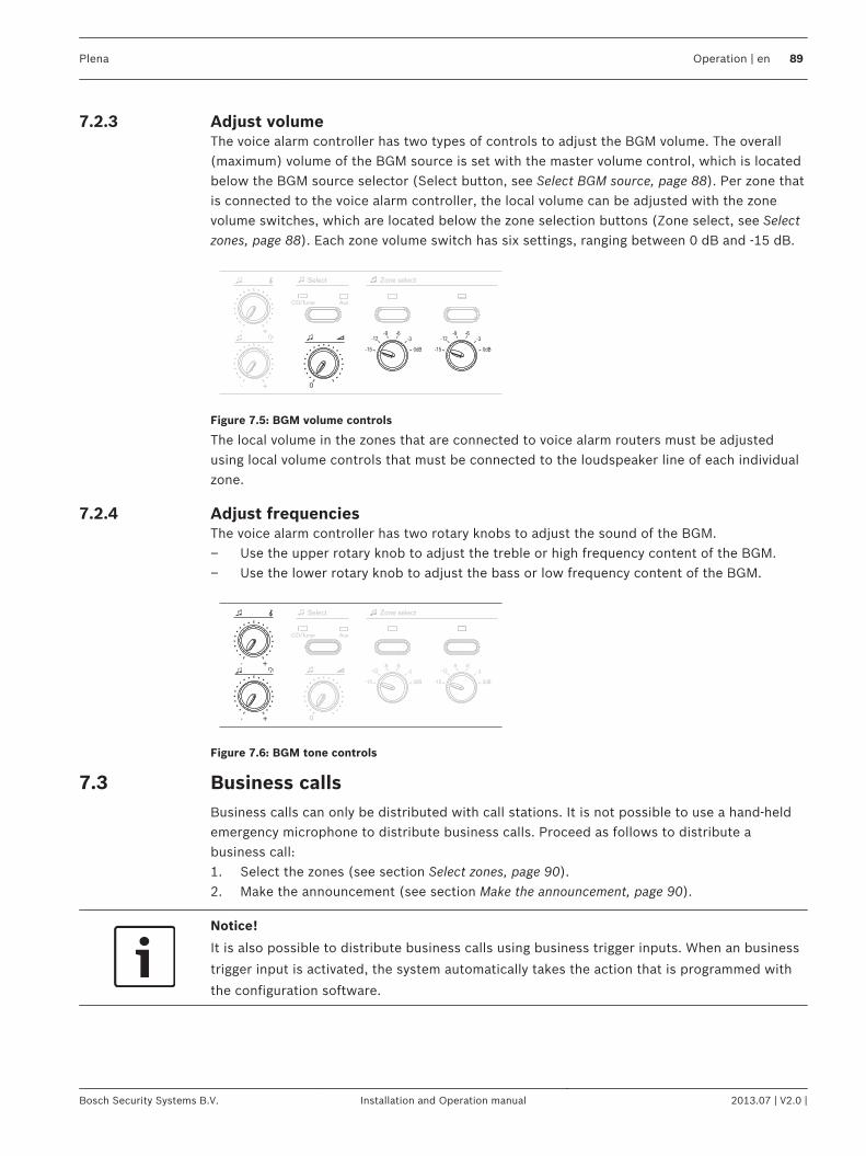
Adjust volumeThe voice alarm controller has two types of controls to adjust the BGM volume. The overall(maximum) volume of the BGM source is set with the master volume control, which is locatedbelow the BGM source selector (Select button, see Select BGM source, page 88). Per zone thatis connected to the voice alarm controller, the local volume can be adjusted with the zonevolume switches, which are located below the zone selection buttons (Zone select, see Selectzones, page 88). Each zone volume switch has six settings, ranging between 0 dB and -15 dB.
0- +
- +
CD/Tuner Aux
Select Zone select
Figure 7.5: BGM volume controls
The local volume in the zones that are connected to voice alarm routers must be adjustedusing local volume controls that must be connected to the loudspeaker line of each individualzone.
Adjust frequenciesThe voice alarm controller has two rotary knobs to adjust the sound of the BGM.– Use the upper rotary knob to adjust the treble or high frequency content of the BGM.– Use the lower rotary knob to adjust the bass or low frequency content of the BGM.
0- +
- +
CD/Tuner Aux
Select Zone select
Figure 7.6: BGM tone controls
Business callsBusiness calls can only be distributed with call stations. It is not possible to use a hand-heldemergency microphone to distribute business calls. Proceed as follows to distribute abusiness call:1. Select the zones (see section Select zones, page 90).2. Make the announcement (see section Make the announcement, page 90).
Notice!
It is also possible to distribute business calls using business trigger inputs. When an business
trigger input is activated, the system automatically takes the action that is programmed with
the configuration software.
7.2.3
7.2.4
7.3
Plena Operation | en 89
Bosch Security Systems B.V. Installation and Operation manual 2013.07 | V2.0 |
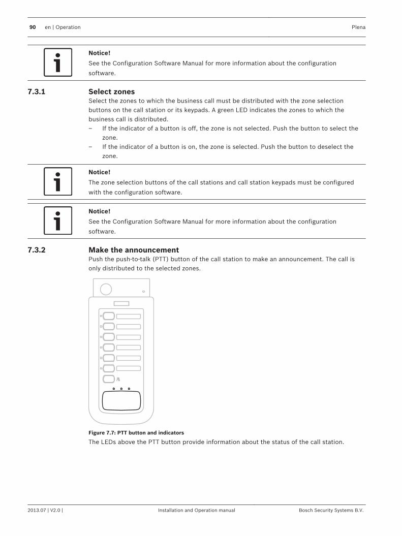
Notice!
See the Configuration Software Manual for more information about the configuration
software.
Select zonesSelect the zones to which the business call must be distributed with the zone selectionbuttons on the call station or its keypads. A green LED indicates the zones to which thebusiness call is distributed.– If the indicator of a button is off, the zone is not selected. Push the button to select the
zone.– If the indicator of a button is on, the zone is selected. Push the button to deselect the
zone.
Notice!
The zone selection buttons of the call stations and call station keypads must be configured
with the configuration software.
Notice!
See the Configuration Software Manual for more information about the configuration
software.
Make the announcementPush the push‑to‑talk (PTT) button of the call station to make an announcement. The call isonly distributed to the selected zones.
Figure 7.7: PTT button and indicators
The LEDs above the PTT button provide information about the status of the call station.
7.3.1
7.3.2
90 en | Operation Plena
2013.07 | V2.0 | Installation and Operation manual Bosch Security Systems B.V.
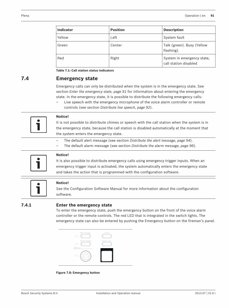
Indicator Position Description
Yellow Left System fault
Green Center Talk (green). Busy (Yellowflashing).
Red Right System in emergency state,call station disabled
Table 7.1: Call station status indicators
Emergency stateEmergency calls can only be distributed when the system is in the emergency state. Seesection Enter the emergency state, page 91 for information about entering the emergencystate. In the emergency state, it is possible to distribute the following emergency calls:– Live speech with the emergency microphone of the voice alarm controller or remote
controls (see section Distribute live speech, page 92).
Notice!
It is not possible to distribute chimes or speech with the call station when the system is in
the emergency state, because the call station is disabled automatically at the moment that
the system enters the emergency state.
– The default alert message (see section Distribute the alert message, page 94).– The default alarm message (see section Distribute the alarm message, page 96).
Notice!
It is also possible to distribute emergency calls using emergency trigger inputs. When an
emergency trigger input is activated, the system automatically enters the emergency state
and takes the action that is programmed with the configuration software.
Notice!
See the Configuration Software Manual for more information about the configuration
software.
Enter the emergency stateTo enter the emergency state, push the emergency button on the front of the voice alarmcontroller or the remote controls. The red LED that is integrated in the switch lights. Theemergency state can also be entered by pushing the Emergency button on the fireman’s panel.
Indicator test
EMG mic
Alert message
Alarm message
All call
Figure 7.8: Emergency button
7.4
7.4.1
Plena Operation | en 91
Bosch Security Systems B.V. Installation and Operation manual 2013.07 | V2.0 |
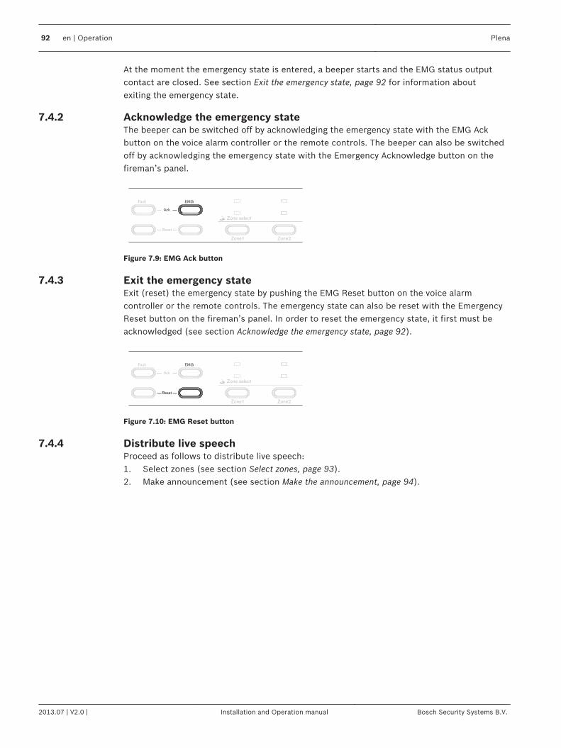
At the moment the emergency state is entered, a beeper starts and the EMG status outputcontact are closed. See section Exit the emergency state, page 92 for information aboutexiting the emergency state.
Acknowledge the emergency stateThe beeper can be switched off by acknowledging the emergency state with the EMG Ackbutton on the voice alarm controller or the remote controls. The beeper can also be switchedoff by acknowledging the emergency state with the Emergency Acknowledge button on thefireman’s panel.
Zone select
Zone1 Zone2
Fault
Reset
EMG
Ack
Figure 7.9: EMG Ack button
Exit the emergency stateExit (reset) the emergency state by pushing the EMG Reset button on the voice alarmcontroller or the remote controls. The emergency state can also be reset with the EmergencyReset button on the fireman’s panel. In order to reset the emergency state, it first must beacknowledged (see section Acknowledge the emergency state, page 92).
Zone select
Zone1 Zone2
Fault
Reset
EMG
Ack
Figure 7.10: EMG Reset button
Distribute live speechProceed as follows to distribute live speech:1. Select zones (see section Select zones, page 93).2. Make announcement (see section Make the announcement, page 94).
7.4.2
7.4.3
7.4.4
92 en | Operation Plena
2013.07 | V2.0 | Installation and Operation manual Bosch Security Systems B.V.
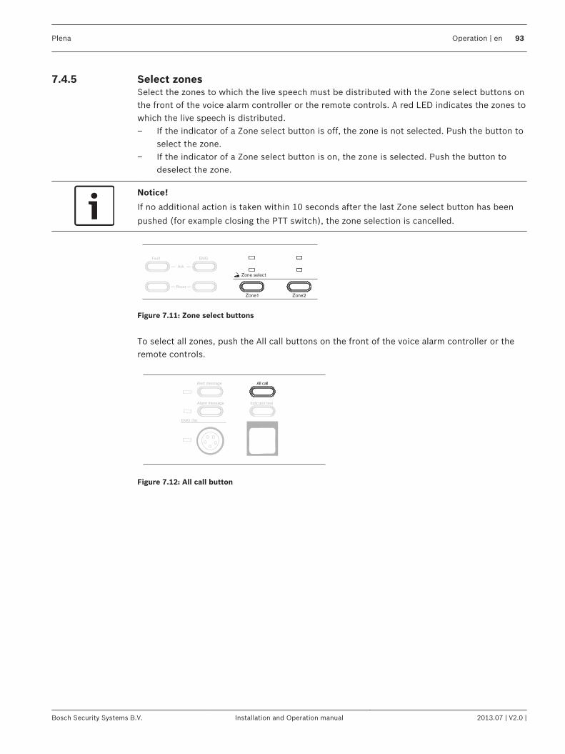
Select zonesSelect the zones to which the live speech must be distributed with the Zone select buttons onthe front of the voice alarm controller or the remote controls. A red LED indicates the zones towhich the live speech is distributed.– If the indicator of a Zone select button is off, the zone is not selected. Push the button to
select the zone.– If the indicator of a Zone select button is on, the zone is selected. Push the button to
deselect the zone.
Notice!
If no additional action is taken within 10 seconds after the last Zone select button has been
pushed (for example closing the PTT switch), the zone selection is cancelled.
Zone select
Zone1 Zone2
Fault
Reset
EMG
Ack
Figure 7.11: Zone select buttons
To select all zones, push the All call buttons on the front of the voice alarm controller or theremote controls.
Indicator test
EMG mic
All callAlert message
Alarm message
Figure 7.12: All call button
7.4.5
Plena Operation | en 93
Bosch Security Systems B.V. Installation and Operation manual 2013.07 | V2.0 |
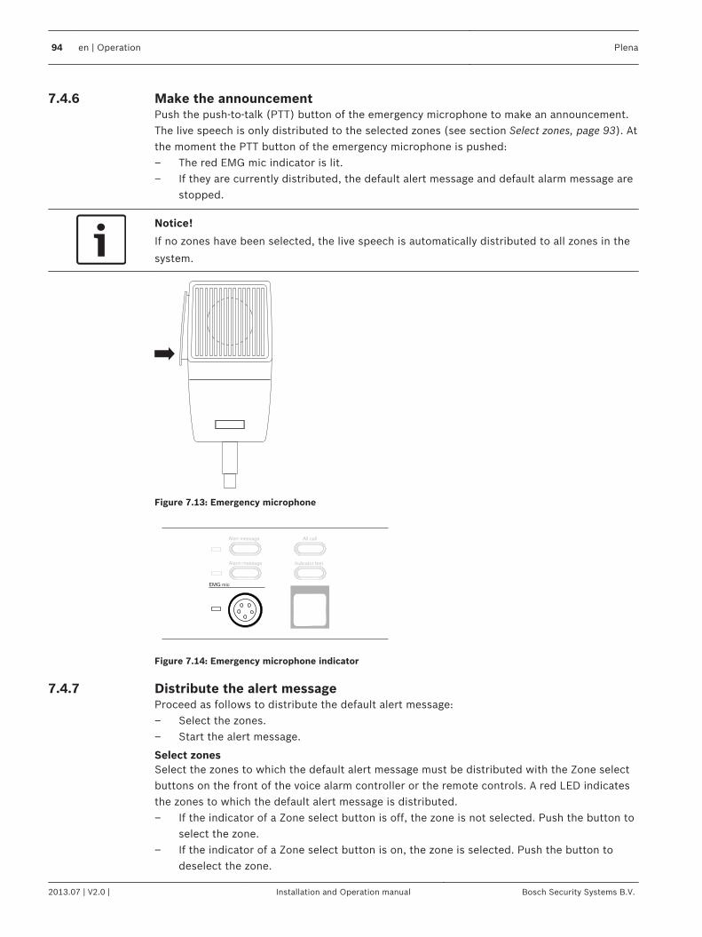
Make the announcementPush the push‑to‑talk (PTT) button of the emergency microphone to make an announcement.The live speech is only distributed to the selected zones (see section Select zones, page 93). Atthe moment the PTT button of the emergency microphone is pushed:– The red EMG mic indicator is lit.– If they are currently distributed, the default alert message and default alarm message are
stopped.
Notice!
If no zones have been selected, the live speech is automatically distributed to all zones in the
system.
Figure 7.13: Emergency microphone
Indicator test
EMG mic
Alert message
Alarm message
All call
Figure 7.14: Emergency microphone indicator
Distribute the alert messageProceed as follows to distribute the default alert message:– Select the zones.– Start the alert message.
Select zonesSelect the zones to which the default alert message must be distributed with the Zone selectbuttons on the front of the voice alarm controller or the remote controls. A red LED indicatesthe zones to which the default alert message is distributed.– If the indicator of a Zone select button is off, the zone is not selected. Push the button to
select the zone.– If the indicator of a Zone select button is on, the zone is selected. Push the button to
deselect the zone.
7.4.6
7.4.7
94 en | Operation Plena
2013.07 | V2.0 | Installation and Operation manual Bosch Security Systems B.V.
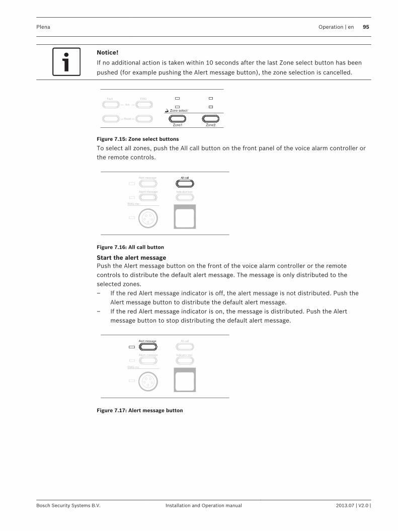
Notice!
If no additional action is taken within 10 seconds after the last Zone select button has been
pushed (for example pushing the Alert message button), the zone selection is cancelled.
Zone select
Zone1 Zone2
Fault
Reset
EMG
Ack
Figure 7.15: Zone select buttons
To select all zones, push the All call button on the front panel of the voice alarm controller orthe remote controls.
Indicator test
EMG mic
All callAlert message
Alarm message
Figure 7.16: All call button
Start the alert messagePush the Alert message button on the front of the voice alarm controller or the remotecontrols to distribute the default alert message. The message is only distributed to theselected zones.– If the red Alert message indicator is off, the alert message is not distributed. Push the
Alert message button to distribute the default alert message.– If the red Alert message indicator is on, the message is distributed. Push the Alert
message button to stop distributing the default alert message.
Indicator test
EMG mic
Alarm message
All callAlert message
Figure 7.17: Alert message button
Plena Operation | en 95
Bosch Security Systems B.V. Installation and Operation manual 2013.07 | V2.0 |
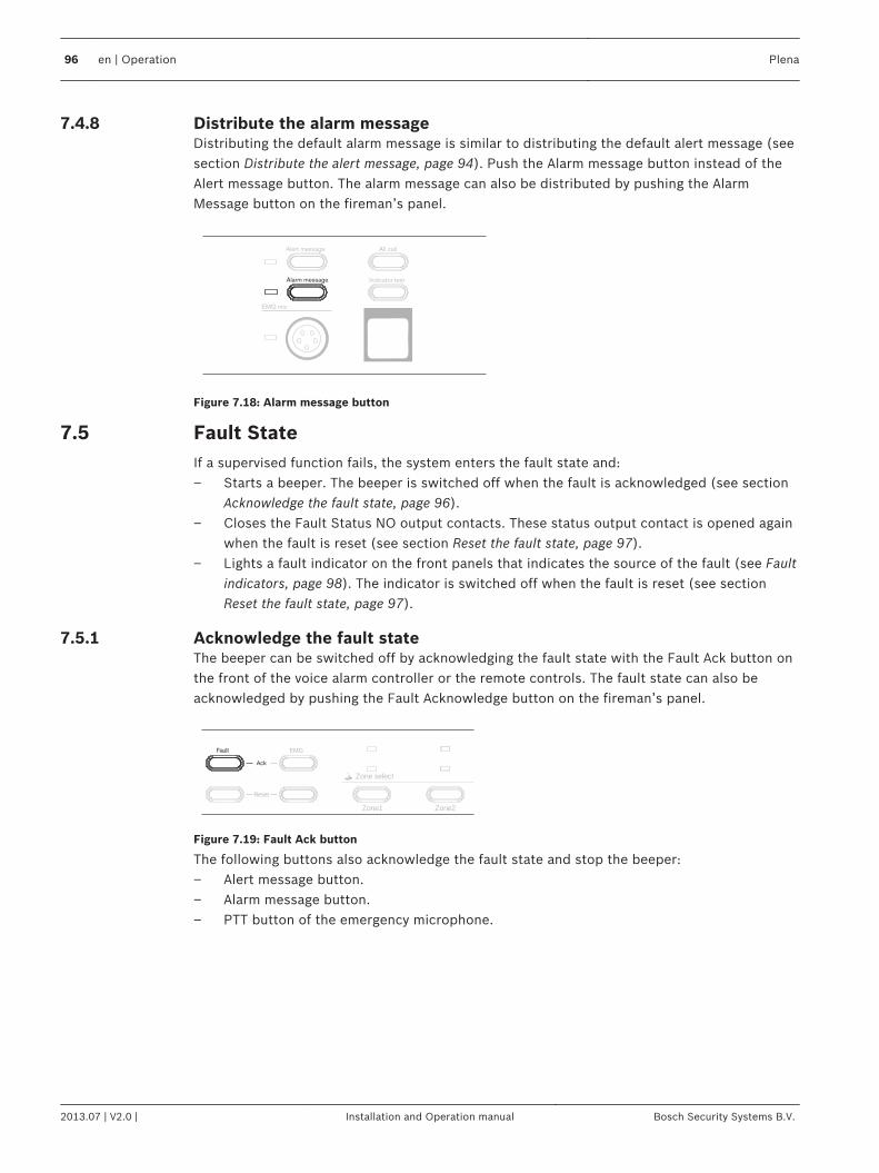
Distribute the alarm messageDistributing the default alarm message is similar to distributing the default alert message (seesection Distribute the alert message, page 94). Push the Alarm message button instead of theAlert message button. The alarm message can also be distributed by pushing the AlarmMessage button on the fireman’s panel.
Indicator test
EMG mic
All callAlert message
Alarm message
Figure 7.18: Alarm message button
Fault StateIf a supervised function fails, the system enters the fault state and:– Starts a beeper. The beeper is switched off when the fault is acknowledged (see section
Acknowledge the fault state, page 96).– Closes the Fault Status NO output contacts. These status output contact is opened again
when the fault is reset (see section Reset the fault state, page 97).– Lights a fault indicator on the front panels that indicates the source of the fault (see Fault
indicators, page 98). The indicator is switched off when the fault is reset (see sectionReset the fault state, page 97).
Acknowledge the fault stateThe beeper can be switched off by acknowledging the fault state with the Fault Ack button onthe front of the voice alarm controller or the remote controls. The fault state can also beacknowledged by pushing the Fault Acknowledge button on the fireman’s panel.
Zone select
Zone1 Zone2
Fault
Reset
EMG
Ack
Figure 7.19: Fault Ack button
The following buttons also acknowledge the fault state and stop the beeper:– Alert message button.– Alarm message button.– PTT button of the emergency microphone.
7.4.8
7.5
7.5.1
96 en | Operation Plena
2013.07 | V2.0 | Installation and Operation manual Bosch Security Systems B.V.
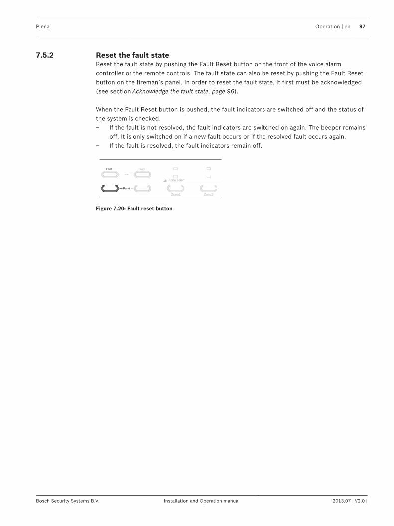
Reset the fault stateReset the fault state by pushing the Fault Reset button on the front of the voice alarmcontroller or the remote controls. The fault state can also be reset by pushing the Fault Resetbutton on the fireman’s panel. In order to reset the fault state, it first must be acknowledged(see section Acknowledge the fault state, page 96). When the Fault Reset button is pushed, the fault indicators are switched off and the status ofthe system is checked.– If the fault is not resolved, the fault indicators are switched on again. The beeper remains
off. It is only switched on if a new fault occurs or if the resolved fault occurs again.– If the fault is resolved, the fault indicators remain off.
Zone select
Zone1 Zone2
Fault
Reset
EMG
Ack
Figure 7.20: Fault reset button
7.5.2
Plena Operation | en 97
Bosch Security Systems B.V. Installation and Operation manual 2013.07 | V2.0 |
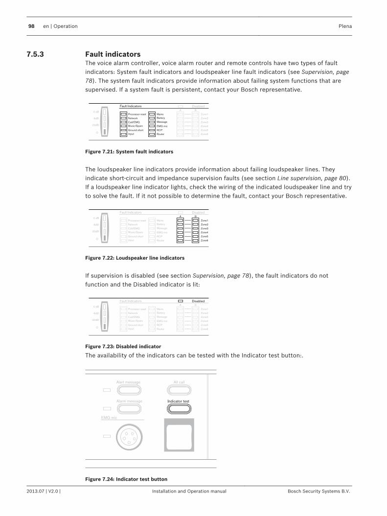
Fault indicatorsThe voice alarm controller, voice alarm router and remote controls have two types of faultindicators: System fault indicators and loudspeaker line fault indicators (see Supervision, page78). The system fault indicators provide information about failing system functions that aresupervised. If a system fault is persistent, contact your Bosch representative.
Zone1
Zone2
Zone3
Zone4
Zone5
Zone6
A B
Disabled
0 dB
-6dB
-20dB
Processor reset
Network
Call/EMG
Music/Spare
Ground short
Input
Mains
Battery
Fault Indicators
Message
EMG mic
RCP
Router
Figure 7.21: System fault indicators
The loudspeaker line indicators provide information about failing loudspeaker lines. Theyindicate short-circuit and impedance supervision faults (see section Line supervision, page 80).If a loudspeaker line indicator lights, check the wiring of the indicated loudspeaker line and tryto solve the fault. If it not possible to determine the fault, contact your Bosch representative.
Processor reset
Network
Call/EMG
Music/Spare
Ground short
Input
Mains
Battery
Fault Indicators Disabled
Message
EMG mic
RCP
Router
0 dB
-6dB
-20dB
Zone1
Zone2
Zone3
Zone4
Zone5
Zone6
A B
Figure 7.22: Loudspeaker line indicators
If supervision is disabled (see section Supervision, page 78), the fault indicators do notfunction and the Disabled indicator is lit:
Processor reset
Network
Call/EMG
Music/Spare
Ground short
Input
Mains
Battery
Zone1
Zone2
Zone3
Zone4
Zone5
Zone6
Fault IndicatorsA B
Disabled
Message
EMG mic
RCP
Router
0 dB
-6dB
-20dB
Figure 7.23: Disabled indicator
The availability of the indicators can be tested with the Indicator test button:.
Indicator test
EMG mic
Alert message
Alarm message
All call
Figure 7.24: Indicator test button
7.5.3
98 en | Operation Plena
2013.07 | V2.0 | Installation and Operation manual Bosch Security Systems B.V.
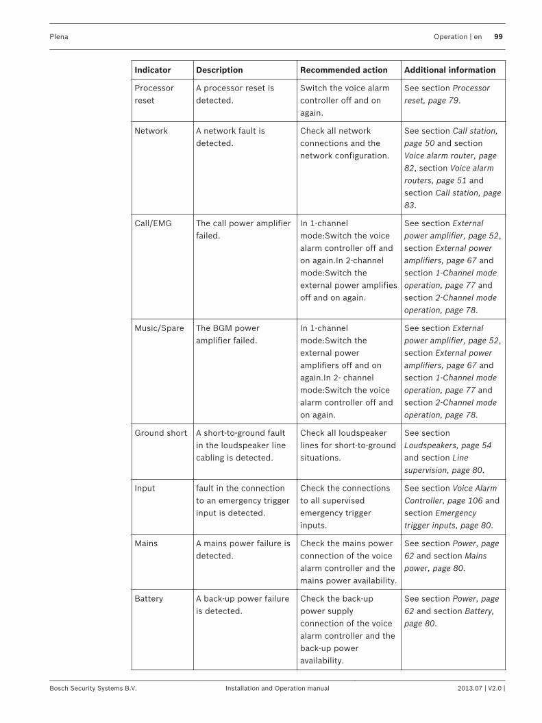
Indicator Description Recommended action Additional information
Processorreset
A processor reset isdetected.
Switch the voice alarmcontroller off and onagain.
See section Processorreset, page 79.
Network A network fault isdetected.
Check all networkconnections and thenetwork configuration.
See section Call station,page 50 and sectionVoice alarm router, page82, section Voice alarmrouters, page 51 andsection Call station, page83.
Call/EMG The call power amplifierfailed.
In 1-channelmode:Switch the voicealarm controller off andon again.In 2-channelmode:Switch theexternal power amplifiesoff and on again.
See section Externalpower amplifier, page 52,section External poweramplifiers, page 67 andsection 1-Channel modeoperation, page 77 andsection 2-Channel modeoperation, page 78.
Music/Spare The BGM poweramplifier failed.
In 1-channelmode:Switch theexternal poweramplifiers off and onagain.In 2- channelmode:Switch the voicealarm controller off andon again.
See section Externalpower amplifier, page 52,section External poweramplifiers, page 67 andsection 1-Channel modeoperation, page 77 andsection 2-Channel modeoperation, page 78.
Ground short A short-to-ground faultin the loudspeaker linecabling is detected.
Check all loudspeakerlines for short-to-groundsituations.
See sectionLoudspeakers, page 54and section Linesupervision, page 80.
Input fault in the connectionto an emergency triggerinput is detected.
Check the connectionsto all supervisedemergency triggerinputs.
See section Voice AlarmController, page 106 andsection Emergencytrigger inputs, page 80.
Mains A mains power failure isdetected.
Check the mains powerconnection of the voicealarm controller and themains power availability.
See section Power, page62 and section Mainspower, page 80.
Battery A back-up power failureis detected.
Check the back-uppower supplyconnection of the voicealarm controller and theback-up poweravailability.
See section Power, page62 and section Battery,page 80.
Plena Operation | en 99
Bosch Security Systems B.V. Installation and Operation manual 2013.07 | V2.0 |
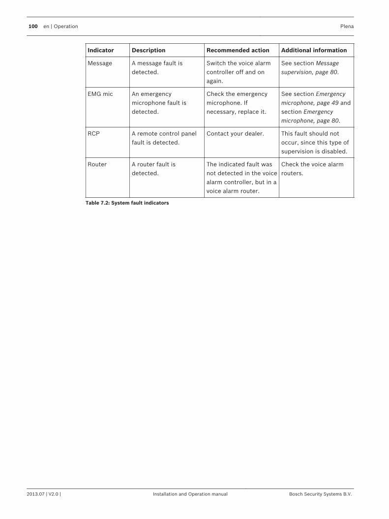
Indicator Description Recommended action Additional information
Message A message fault isdetected.
Switch the voice alarmcontroller off and onagain.
See section Messagesupervision, page 80.
EMG mic An emergencymicrophone fault isdetected.
Check the emergencymicrophone. Ifnecessary, replace it.
See section Emergencymicrophone, page 49 andsection Emergencymicrophone, page 80.
RCP A remote control panelfault is detected.
Contact your dealer. This fault should notoccur, since this type ofsupervision is disabled.
Router A router fault isdetected.
The indicated fault wasnot detected in the voicealarm controller, but in avoice alarm router.
Check the voice alarmrouters.
Table 7.2: System fault indicators
100 en | Operation Plena
2013.07 | V2.0 | Installation and Operation manual Bosch Security Systems B.V.
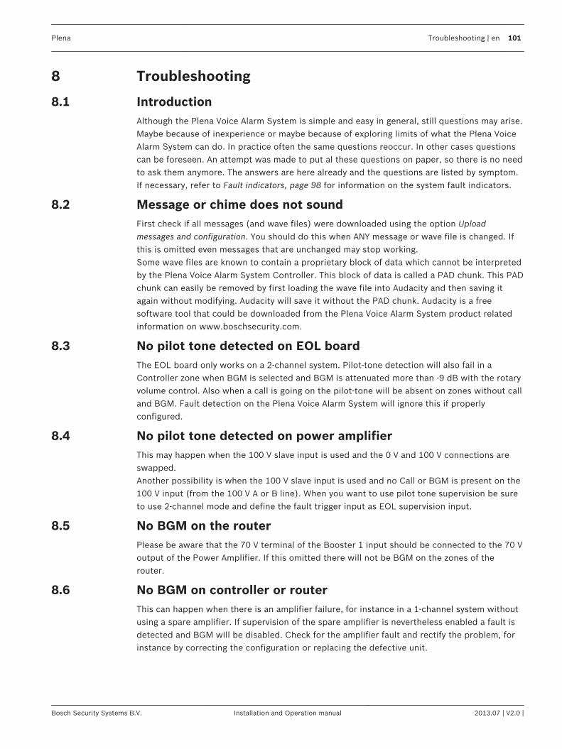
Troubleshooting
IntroductionAlthough the Plena Voice Alarm System is simple and easy in general, still questions may arise.Maybe because of inexperience or maybe because of exploring limits of what the Plena VoiceAlarm System can do. In practice often the same questions reoccur. In other cases questionscan be foreseen. An attempt was made to put al these questions on paper, so there is no needto ask them anymore. The answers are here already and the questions are listed by symptom.If necessary, refer to Fault indicators, page 98 for information on the system fault indicators.
Message or chime does not soundFirst check if all messages (and wave files) were downloaded using the option Uploadmessages and configuration. You should do this when ANY message or wave file is changed. Ifthis is omitted even messages that are unchanged may stop working.Some wave files are known to contain a proprietary block of data which cannot be interpretedby the Plena Voice Alarm System Controller. This block of data is called a PAD chunk. This PADchunk can easily be removed by first loading the wave file into Audacity and then saving itagain without modifying. Audacity will save it without the PAD chunk. Audacity is a freesoftware tool that could be downloaded from the Plena Voice Alarm System product relatedinformation on www.boschsecurity.com.
No pilot tone detected on EOL boardThe EOL board only works on a 2-channel system. Pilot‑tone detection will also fail in aController zone when BGM is selected and BGM is attenuated more than -9 dB with the rotaryvolume control. Also when a call is going on the pilot‑tone will be absent on zones without calland BGM. Fault detection on the Plena Voice Alarm System will ignore this if properlyconfigured.
No pilot tone detected on power amplifierThis may happen when the 100 V slave input is used and the 0 V and 100 V connections areswapped.Another possibility is when the 100 V slave input is used and no Call or BGM is present on the100 V input (from the 100 V A or B line). When you want to use pilot tone supervision be sureto use 2‑channel mode and define the fault trigger input as EOL supervision input.
No BGM on the routerPlease be aware that the 70 V terminal of the Booster 1 input should be connected to the 70 Voutput of the Power Amplifier. If this omitted there will not be BGM on the zones of therouter.
No BGM on controller or routerThis can happen when there is an amplifier failure, for instance in a 1‑channel system withoutusing a spare amplifier. If supervision of the spare amplifier is nevertheless enabled a fault isdetected and BGM will be disabled. Check for the amplifier fault and rectify the problem, forinstance by correcting the configuration or replacing the defective unit.
8
8.1
8.2
8.3
8.4
8.5
8.6
Plena Troubleshooting | en 101
Bosch Security Systems B.V. Installation and Operation manual 2013.07 | V2.0 |
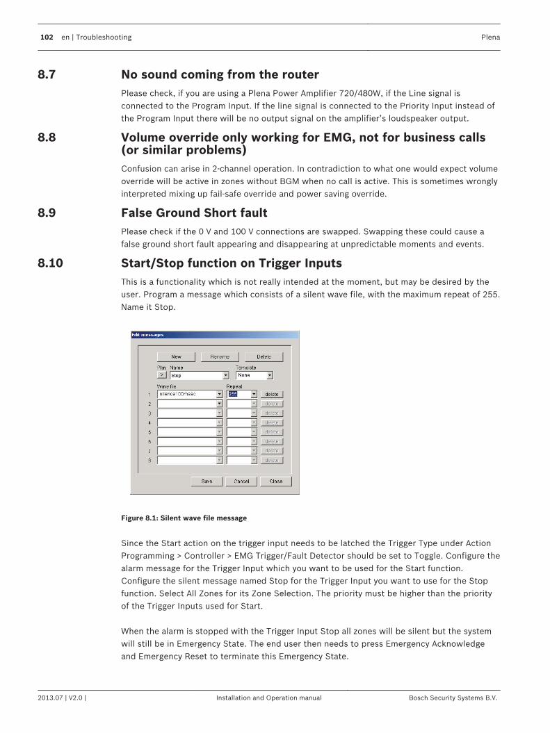
No sound coming from the routerPlease check, if you are using a Plena Power Amplifier 720/480W, if the Line signal isconnected to the Program Input. If the line signal is connected to the Priority Input instead ofthe Program Input there will be no output signal on the amplifier’s loudspeaker output.
Volume override only working for EMG, not for business calls(or similar problems)Confusion can arise in 2‑channel operation. In contradiction to what one would expect volumeoverride will be active in zones without BGM when no call is active. This is sometimes wronglyinterpreted mixing up fail-safe override and power saving override.
False Ground Short faultPlease check if the 0 V and 100 V connections are swapped. Swapping these could cause afalse ground short fault appearing and disappearing at unpredictable moments and events.
Start/Stop function on Trigger InputsThis is a functionality which is not really intended at the moment, but may be desired by theuser. Program a message which consists of a silent wave file, with the maximum repeat of 255.Name it Stop.
Figure 8.1: Silent wave file message
Since the Start action on the trigger input needs to be latched the Trigger Type under ActionProgramming > Controller > EMG Trigger/Fault Detector should be set to Toggle. Configure thealarm message for the Trigger Input which you want to be used for the Start function.Configure the silent message named Stop for the Trigger Input you want to use for the Stopfunction. Select All Zones for its Zone Selection. The priority must be higher than the priorityof the Trigger Inputs used for Start. When the alarm is stopped with the Trigger Input Stop all zones will be silent but the systemwill still be in Emergency State. The end user then needs to press Emergency Acknowledgeand Emergency Reset to terminate this Emergency State.
8.7
8.8
8.9
8.10
102 en | Troubleshooting Plena
2013.07 | V2.0 | Installation and Operation manual Bosch Security Systems B.V.
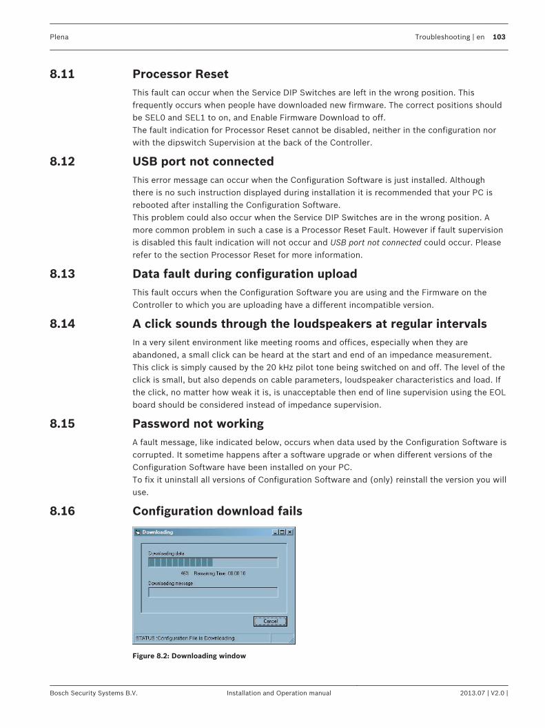
Processor ResetThis fault can occur when the Service DIP Switches are left in the wrong position. Thisfrequently occurs when people have downloaded new firmware. The correct positions shouldbe SEL0 and SEL1 to on, and Enable Firmware Download to off.The fault indication for Processor Reset cannot be disabled, neither in the configuration norwith the dipswitch Supervision at the back of the Controller.
USB port not connectedThis error message can occur when the Configuration Software is just installed. Althoughthere is no such instruction displayed during installation it is recommended that your PC isrebooted after installing the Configuration Software.This problem could also occur when the Service DIP Switches are in the wrong position. Amore common problem in such a case is a Processor Reset Fault. However if fault supervisionis disabled this fault indication will not occur and USB port not connected could occur. Pleaserefer to the section Processor Reset for more information.
Data fault during configuration uploadThis fault occurs when the Configuration Software you are using and the Firmware on theController to which you are uploading have a different incompatible version.
A click sounds through the loudspeakers at regular intervalsIn a very silent environment like meeting rooms and offices, especially when they areabandoned, a small click can be heard at the start and end of an impedance measurement.This click is simply caused by the 20 kHz pilot tone being switched on and off. The level of theclick is small, but also depends on cable parameters, loudspeaker characteristics and load. Ifthe click, no matter how weak it is, is unacceptable then end of line supervision using the EOLboard should be considered instead of impedance supervision.
Password not workingA fault message, like indicated below, occurs when data used by the Configuration Software iscorrupted. It sometime happens after a software upgrade or when different versions of theConfiguration Software have been installed on your PC.To fix it uninstall all versions of Configuration Software and (only) reinstall the version you willuse.
Configuration download fails
Figure 8.2: Downloading window
8.11
8.12
8.13
8.14
8.15
8.16
Plena Troubleshooting | en 103
Bosch Security Systems B.V. Installation and Operation manual 2013.07 | V2.0 |
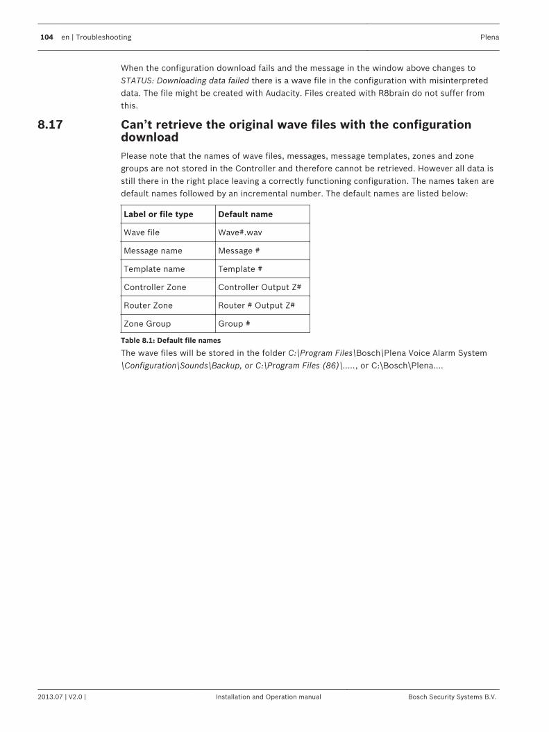
When the configuration download fails and the message in the window above changes toSTATUS: Downloading data failed there is a wave file in the configuration with misinterpreteddata. The file might be created with Audacity. Files created with R8brain do not suffer fromthis.
Can’t retrieve the original wave files with the configurationdownloadPlease note that the names of wave files, messages, message templates, zones and zonegroups are not stored in the Controller and therefore cannot be retrieved. However all data isstill there in the right place leaving a correctly functioning configuration. The names taken aredefault names followed by an incremental number. The default names are listed below:
Label or file type Default name
Wave file Wave#.wav
Message name Message #
Template name Template #
Controller Zone Controller Output Z#
Router Zone Router # Output Z#
Zone Group Group #
Table 8.1: Default file names
The wave files will be stored in the folder C:\Program Files\Bosch\Plena Voice Alarm System\Configuration\Sounds\Backup, or C:\Program Files (86)\....., or C:\Bosch\Plena....
8.17
104 en | Troubleshooting Plena
2013.07 | V2.0 | Installation and Operation manual Bosch Security Systems B.V.
MaintenanceThe system requires minimum maintenance.To keep the system in good condition, do the following:– Clean the units (section Clean the units, page 105)– Clean the air inlets (section Clean air inlets, page 105)– Check connectors and grounding (section Check the connectors and grounding, page
105).
!Warning!
Dangerous mains voltages are present inside the units. Disconnect the main power supply
before you do any maintenance.
Clean the unitsPeriodically you must clean all units with a damp, lint-free cloth.
Clean air inletsThe 19‑inch units can collect dust as a result of the internal fans. Once a year you should use avacuum cleaner to clean the air inlets of all units in the 19‑inch racks.
Check the connectors and groundingPeriodically check:– All cable connections.– The ground (PE) connection of the system components.
9
9.1
9.2
9.3
Plena Maintenance | en 105
Bosch Security Systems B.V. Installation and Operation manual 2013.07 | V2.0 |
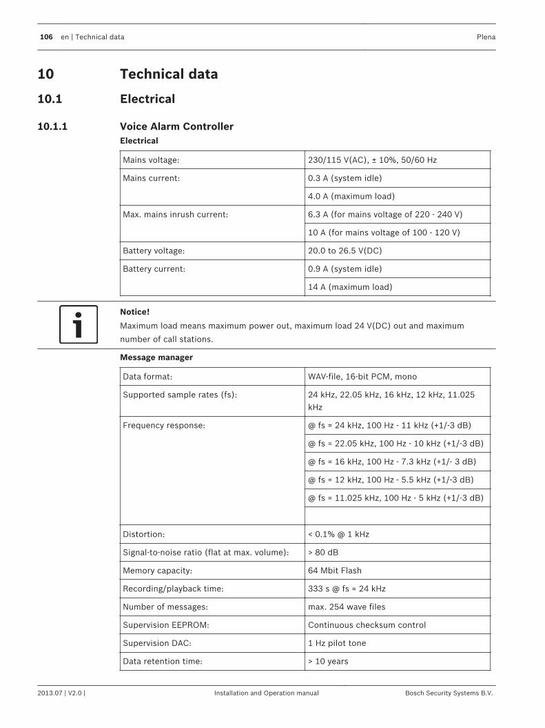
Technical data
Electrical
Voice Alarm ControllerElectrical
Mains voltage: 230/115 V(AC), ± 10%, 50/60 Hz
Mains current: 0.3 A (system idle)
4.0 A (maximum load)
Max. mains inrush current: 6.3 A (for mains voltage of 220 - 240 V)
10 A (for mains voltage of 100 - 120 V)
Battery voltage: 20.0 to 26.5 V(DC)
Battery current: 0.9 A (system idle)
14 A (maximum load)
Notice!
Maximum load means maximum power out, maximum load 24 V(DC) out and maximum
number of call stations.
Message manager
Data format: WAV-file, 16-bit PCM, mono
Supported sample rates (fs): 24 kHz, 22.05 kHz, 16 kHz, 12 kHz, 11.025kHz
Frequency response:
@ fs = 24 kHz, 100 Hz - 11 kHz (+1/-3 dB)
@ fs = 22.05 kHz, 100 Hz - 10 kHz (+1/-3 dB)
@ fs = 16 kHz, 100 Hz - 7.3 kHz (+1/- 3 dB)
@ fs = 12 kHz, 100 Hz - 5.5 kHz (+1/-3 dB)
@ fs = 11.025 kHz, 100 Hz - 5 kHz (+1/-3 dB)
Distortion: < 0.1% @ 1 kHz
Signal-to-noise ratio (flat at max. volume): > 80 dB
Memory capacity: 64 Mbit Flash
Recording/playback time: 333 s @ fs = 24 kHz
Number of messages: max. 254 wave files
Supervision EEPROM: Continuous checksum control
Supervision DAC: 1 Hz pilot tone
Data retention time: > 10 years
10
10.1
10.1.1
106 en | Technical data Plena
2013.07 | V2.0 | Installation and Operation manual Bosch Security Systems B.V.
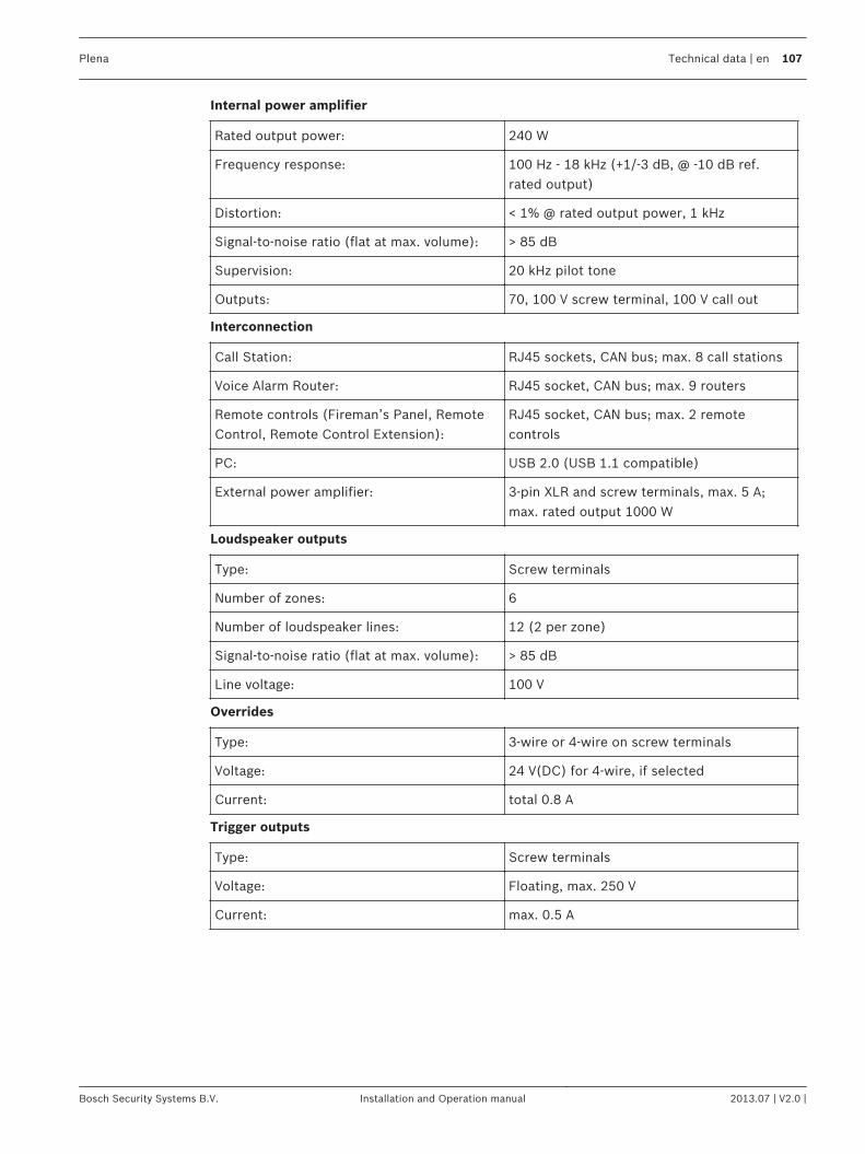
Internal power amplifier
Rated output power: 240 W
Frequency response: 100 Hz - 18 kHz (+1/-3 dB, @ -10 dB ref.rated output)
Distortion: < 1% @ rated output power, 1 kHz
Signal-to-noise ratio (flat at max. volume): > 85 dB
Supervision: 20 kHz pilot tone
Outputs: 70, 100 V screw terminal, 100 V call out
Interconnection
Call Station: RJ45 sockets, CAN bus; max. 8 call stations
Voice Alarm Router: RJ45 socket, CAN bus; max. 9 routers
Remote controls (Fireman’s Panel, RemoteControl, Remote Control Extension):
RJ45 socket, CAN bus; max. 2 remotecontrols
PC: USB 2.0 (USB 1.1 compatible)
External power amplifier: 3-pin XLR and screw terminals, max. 5 A;max. rated output 1000 W
Loudspeaker outputs
Type: Screw terminals
Number of zones: 6
Number of loudspeaker lines: 12 (2 per zone)
Signal-to-noise ratio (flat at max. volume): > 85 dB
Line voltage: 100 V
Overrides
Type: 3-wire or 4-wire on screw terminals
Voltage: 24 V(DC) for 4-wire, if selected
Current: total 0.8 A
Trigger outputs
Type: Screw terminals
Voltage: Floating, max. 250 V
Current: max. 0.5 A
Plena Technical data | en 107
Bosch Security Systems B.V. Installation and Operation manual 2013.07 | V2.0 |
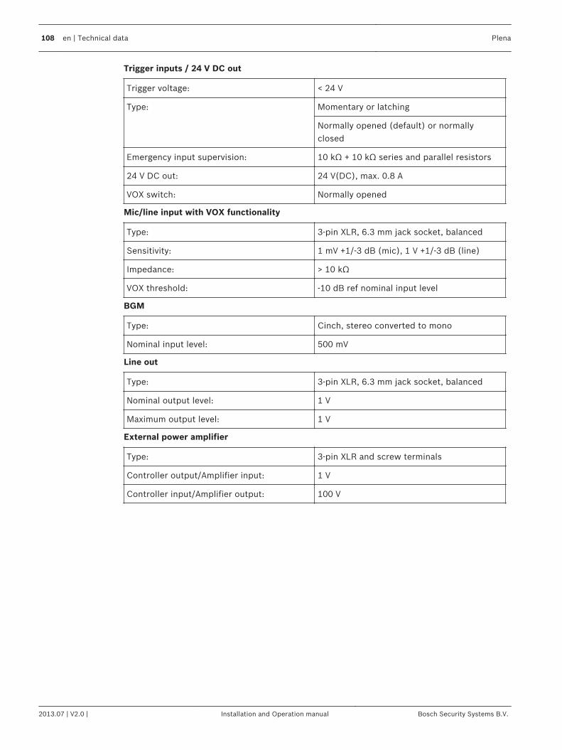
Trigger inputs / 24 V DC out
Trigger voltage: < 24 V
Type:
Momentary or latching
Normally opened (default) or normallyclosed
Emergency input supervision: 10 kΩ + 10 kΩ series and parallel resistors
24 V DC out: 24 V(DC), max. 0.8 A
VOX switch: Normally opened
Mic/line input with VOX functionality
Type: 3-pin XLR, 6.3 mm jack socket, balanced
Sensitivity: 1 mV +1/-3 dB (mic), 1 V +1/-3 dB (line)
Impedance: > 10 kΩ
VOX threshold: -10 dB ref nominal input level
BGM
Type: Cinch, stereo converted to mono
Nominal input level: 500 mV
Line out
Type: 3-pin XLR, 6.3 mm jack socket, balanced
Nominal output level: 1 V
Maximum output level: 1 V
External power amplifier
Type: 3-pin XLR and screw terminals
Controller output/Amplifier input: 1 V
Controller input/Amplifier output: 100 V
108 en | Technical data Plena
2013.07 | V2.0 | Installation and Operation manual Bosch Security Systems B.V.
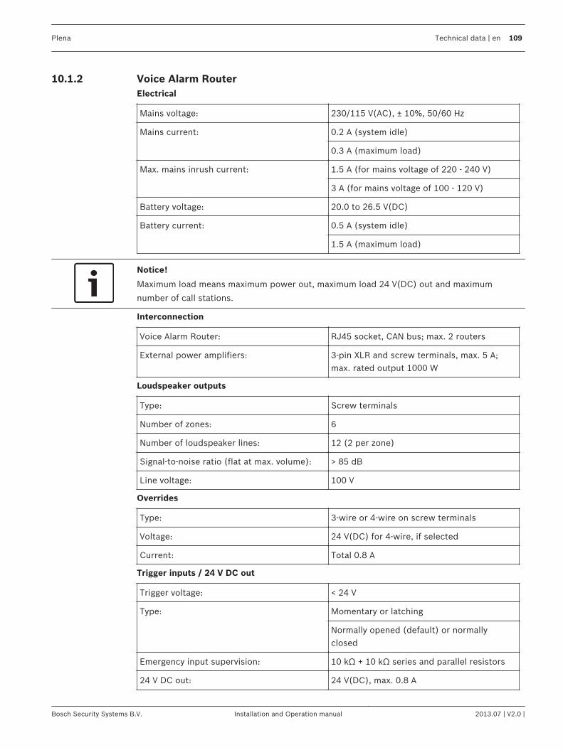
Voice Alarm RouterElectrical
Mains voltage: 230/115 V(AC), ± 10%, 50/60 Hz
Mains current: 0.2 A (system idle)
0.3 A (maximum load)
Max. mains inrush current: 1.5 A (for mains voltage of 220 - 240 V)
3 A (for mains voltage of 100 - 120 V)
Battery voltage: 20.0 to 26.5 V(DC)
Battery current: 0.5 A (system idle)
1.5 A (maximum load)
Notice!
Maximum load means maximum power out, maximum load 24 V(DC) out and maximum
number of call stations.
Interconnection
Voice Alarm Router: RJ45 socket, CAN bus; max. 2 routers
External power amplifiers: 3-pin XLR and screw terminals, max. 5 A;max. rated output 1000 W
Loudspeaker outputs
Type: Screw terminals
Number of zones: 6
Number of loudspeaker lines: 12 (2 per zone)
Signal-to-noise ratio (flat at max. volume): > 85 dB
Line voltage: 100 V
Overrides
Type: 3‑wire or 4‑wire on screw terminals
Voltage: 24 V(DC) for 4‑wire, if selected
Current: Total 0.8 A
Trigger inputs / 24 V DC out
Trigger voltage: < 24 V
Type:
Momentary or latching
Normally opened (default) or normallyclosed
Emergency input supervision: 10 kΩ + 10 kΩ series and parallel resistors
24 V DC out: 24 V(DC), max. 0.8 A
10.1.2
Plena Technical data | en 109
Bosch Security Systems B.V. Installation and Operation manual 2013.07 | V2.0 |
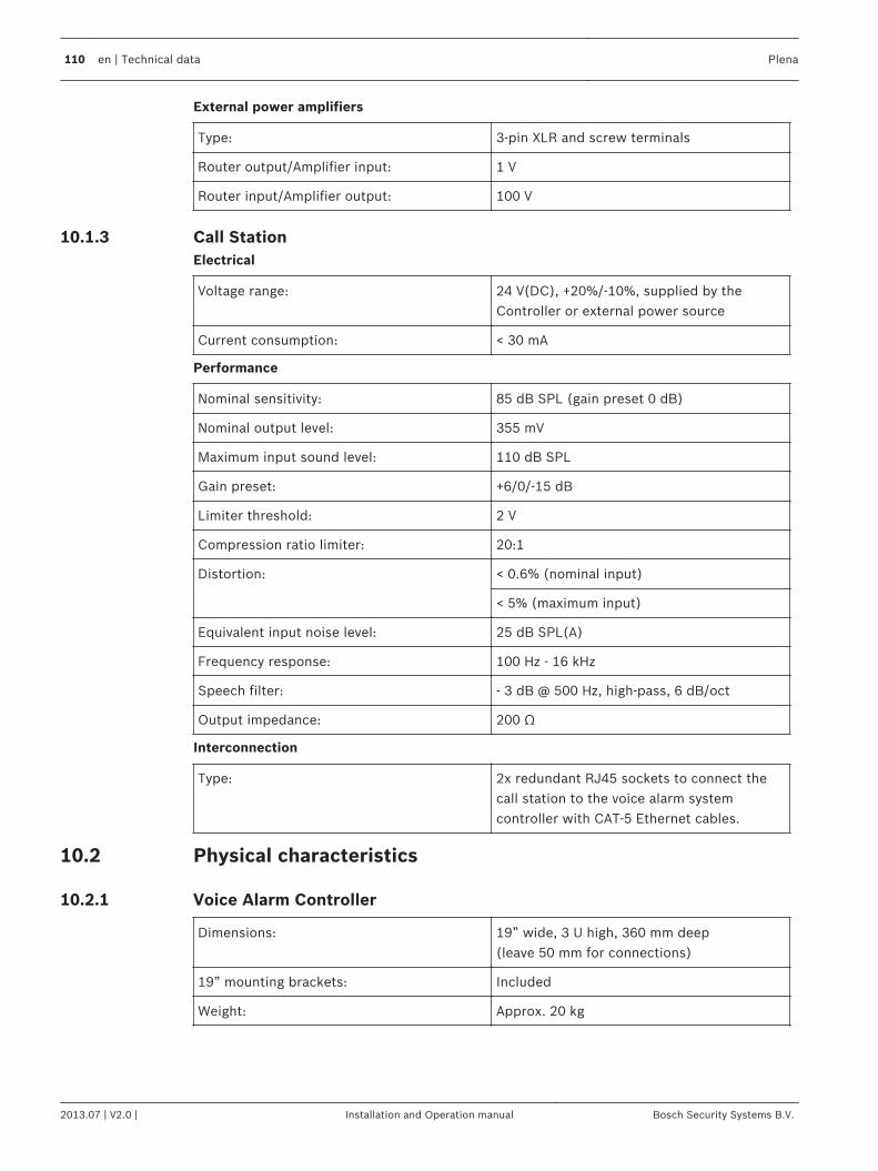
External power amplifiers
Type: 3-pin XLR and screw terminals
Router output/Amplifier input: 1 V
Router input/Amplifier output: 100 V
Call StationElectrical
Voltage range: 24 V(DC), +20%/-10%, supplied by theController or external power source
Current consumption: < 30 mA
Performance
Nominal sensitivity: 85 dB SPL (gain preset 0 dB)
Nominal output level: 355 mV
Maximum input sound level: 110 dB SPL
Gain preset: +6/0/-15 dB
Limiter threshold: 2 V
Compression ratio limiter: 20:1
Distortion:
< 0.6% (nominal input)
< 5% (maximum input)
Equivalent input noise level: 25 dB SPL(A)
Frequency response: 100 Hz - 16 kHz
Speech filter: - 3 dB @ 500 Hz, high-pass, 6 dB/oct
Output impedance: 200 Ω
Interconnection
Type: 2x redundant RJ45 sockets to connect thecall station to the voice alarm systemcontroller with CAT‑5 Ethernet cables.
Physical characteristics
Voice Alarm Controller
Dimensions: 19” wide, 3 U high, 360 mm deep(leave 50 mm for connections)
19” mounting brackets: Included
Weight: Approx. 20 kg
10.1.3
10.2
10.2.1
110 en | Technical data Plena
2013.07 | V2.0 | Installation and Operation manual Bosch Security Systems B.V.
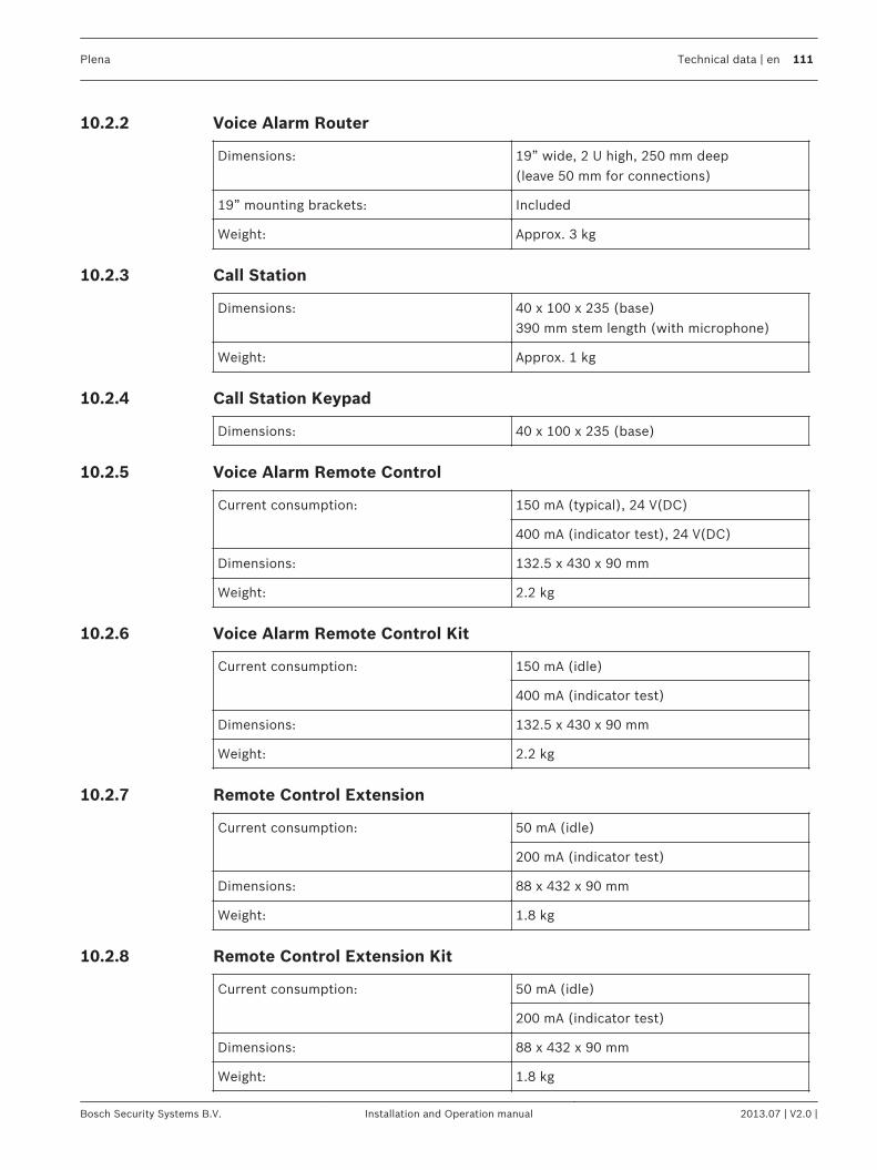
Voice Alarm Router
Dimensions: 19” wide, 2 U high, 250 mm deep(leave 50 mm for connections)
19” mounting brackets: Included
Weight: Approx. 3 kg
Call Station
Dimensions: 40 x 100 x 235 (base)390 mm stem length (with microphone)
Weight: Approx. 1 kg
Call Station Keypad
Dimensions: 40 x 100 x 235 (base)
Voice Alarm Remote Control
Current consumption:
150 mA (typical), 24 V(DC)
400 mA (indicator test), 24 V(DC)
Dimensions: 132.5 x 430 x 90 mm
Weight: 2.2 kg
Voice Alarm Remote Control Kit
Current consumption:
150 mA (idle)
400 mA (indicator test)
Dimensions: 132.5 x 430 x 90 mm
Weight: 2.2 kg
Remote Control Extension
Current consumption:
50 mA (idle)
200 mA (indicator test)
Dimensions: 88 x 432 x 90 mm
Weight: 1.8 kg
Remote Control Extension Kit
Current consumption:
50 mA (idle)
200 mA (indicator test)
Dimensions: 88 x 432 x 90 mm
Weight: 1.8 kg
10.2.2
10.2.3
10.2.4
10.2.5
10.2.6
10.2.7
10.2.8
Plena Technical data | en 111
Bosch Security Systems B.V. Installation and Operation manual 2013.07 | V2.0 |
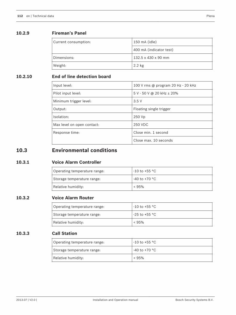
Fireman’s Panel
Current consumption:
150 mA (idle)
400 mA (indicator test)
Dimensions: 132.5 x 430 x 90 mm
Weight: 2.2 kg
End of line detection board
Input level: 100 V rms @ program 20 Hz - 20 kHz
Pilot input level: 5 V - 50 V @ 20 kHz ± 20%
Minimum trigger level: 3.5 V
Output: Floating single trigger
Isolation: 250 Vp
Max level on open contact: 250 VDC
Response time:
Close min. 1 second
Close max. 10 seconds
Environmental conditions
Voice Alarm Controller
Operating temperature range: -10 to +55 °C
Storage temperature range: -40 to +70 °C
Relative humidity: < 95%
Voice Alarm Router
Operating temperature range: -10 to +55 °C
Storage temperature range: -25 to +55 °C
Relative humidity: < 95%
Call Station
Operating temperature range: -10 to +55 °C
Storage temperature range: -40 to +70 °C
Relative humidity: < 95%
10.2.9
10.2.10
10.3
10.3.1
10.3.2
10.3.3
112 en | Technical data Plena
2013.07 | V2.0 | Installation and Operation manual Bosch Security Systems B.V.
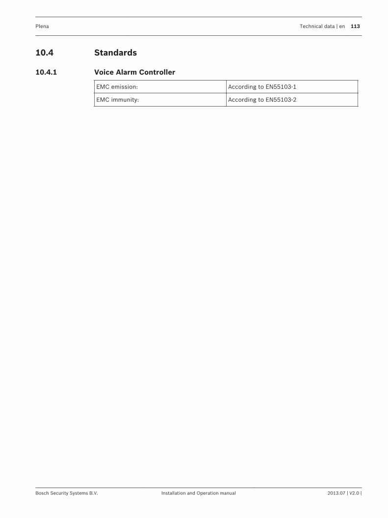
Standards
Voice Alarm Controller
EMC emission: According to EN55103-1
EMC immunity: According to EN55103-2
10.4
10.4.1
Plena Technical data | en 113
Bosch Security Systems B.V. Installation and Operation manual 2013.07 | V2.0 |
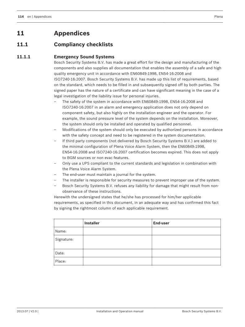
Appendices
Compliancy checklists
Emergency Sound SystemsBosch Security Systems B.V. has made a great effort for the design and manufacturing of thecomponents and also supplies all documentation that enables the assembly of a safe and highquality emergency unit in accordance with EN60849:1998, EN54-16:2008 andISO7240-16:2007. Bosch Security Systems B.V. has made up this list of requirements, basedon the standard, which needs to be filled in and subsequently signed off by both parties. Thesigned paper has the nature of a certificate and can have significant meaning in the case of alegal investigation of the liability issue for personal injuries.– The safety of the system in accordance with EN60849:1998, EN54-16:2008 and
ISO7240-16:2007 in an alarm and emergency application does not only depend oncomponent safety, but also highly on the installation engineer and the operator. Forexample, the sound pressure level of the system depends on the installation. Moreover,the system should only be installed and operated by qualified personnel.
– Modifications of the system should only be executed by authorized persons in accordancewith the safety concept and need to be registered in the system documentation.
– If third party components (not delivered by Bosch Security Systems B.V.) are added tothe minimal configuration of Plena Voice Alarm System, then the EN60849:1998,EN54‑16:2008 and ISO7240‑16:2007 certification becomes expired. This does not applyto BGM sources or non evac features.
– Only use a UPS compliant to the current standards and legislation in combination withthe Plena Voice Alarm System.
– The end-user must maintain a journal for the system.– The installer is responsible for security measures to prevent improper use of the system.– Bosch Security Systems B.V. refuses any liability for damage that might result from non-
observance of these instructions.Herewith the undersigned states that he/she has processed for him/her applicablerequirements, as specified in this document, in an adequate way and has confirmed this factby signing the rightmost column of each applicable requirement.
Installer End-user
Name:
Signature:
Date:
Place:
11
11.1
11.1.1
114 en | Appendices Plena
2013.07 | V2.0 | Installation and Operation manual Bosch Security Systems B.V.

List of authorized end-users
Name Name
Plena Appendices | en 115
Bosch Security Systems B.V. Installation and Operation manual 2013.07 | V2.0 |
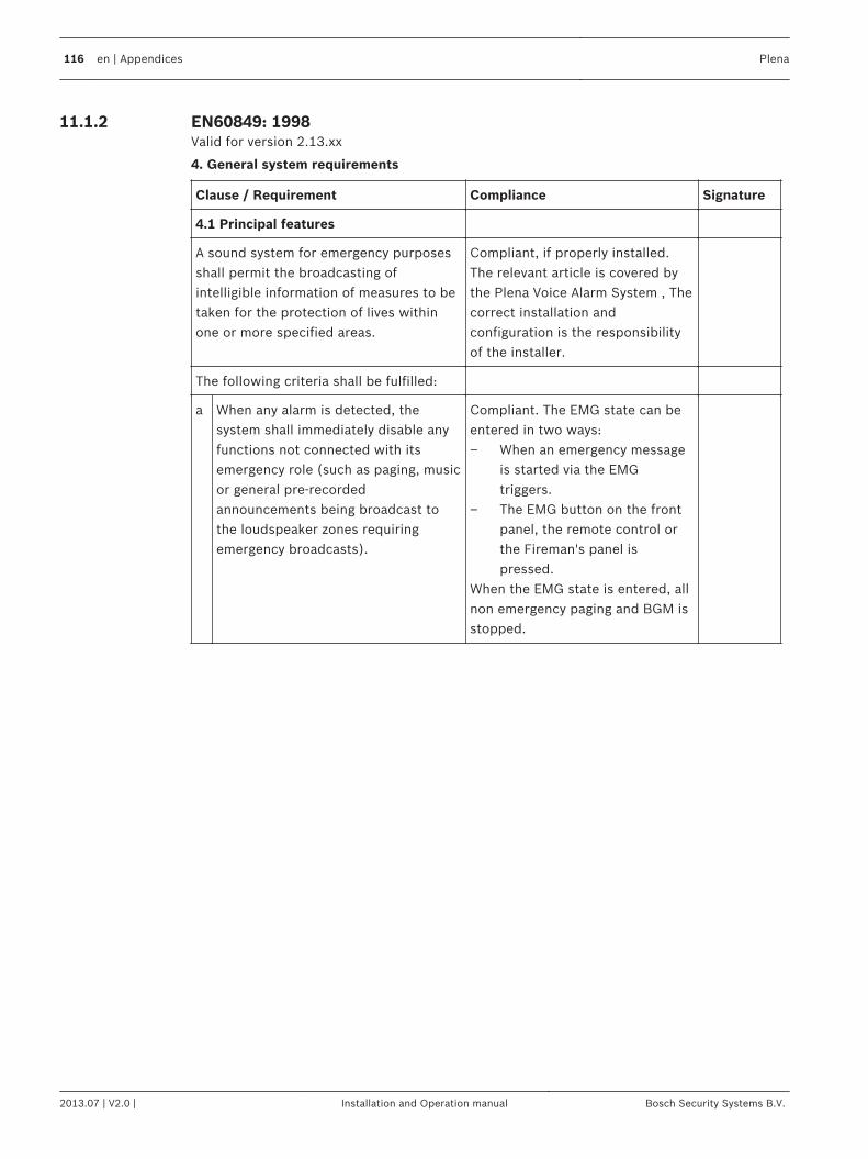
EN60849: 1998Valid for version 2.13.xx
4. General system requirements
Clause / Requirement Compliance Signature
4.1 Principal features
A sound system for emergency purposesshall permit the broadcasting ofintelligible information of measures to betaken for the protection of lives withinone or more specified areas.
Compliant, if properly installed.The relevant article is covered bythe Plena Voice Alarm System , Thecorrect installation andconfiguration is the responsibilityof the installer.
The following criteria shall be fulfilled:
a When any alarm is detected, thesystem shall immediately disable anyfunctions not connected with itsemergency role (such as paging, musicor general pre-recordedannouncements being broadcast tothe loudspeaker zones requiringemergency broadcasts).
Compliant. The EMG state can beentered in two ways:– When an emergency message
is started via the EMGtriggers.
– The EMG button on the frontpanel, the remote control orthe Fireman's panel ispressed.
When the EMG state is entered, allnon emergency paging and BGM isstopped.
11.1.2
116 en | Appendices Plena
2013.07 | V2.0 | Installation and Operation manual Bosch Security Systems B.V.
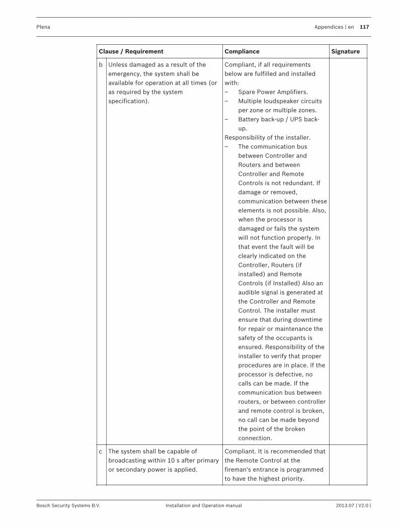
Clause / Requirement Compliance Signature
b Unless damaged as a result of theemergency, the system shall beavailable for operation at all times (oras required by the systemspecification).
Compliant, if all requirementsbelow are fulfilled and installedwith:– Spare Power Amplifiers.– Multiple loudspeaker circuits
per zone or multiple zones.– Battery back-up / UPS back-
up.Responsibility of the installer.– The communication bus
between Controller andRouters and betweenController and RemoteControls is not redundant. Ifdamage or removed,communication between theseelements is not possible. Also,when the processor isdamaged or fails the systemwill not function properly. Inthat event the fault will beclearly indicated on theController, Routers (ifinstalled) and RemoteControls (if Installed) Also anaudible signal is generated atthe Controller and RemoteControl. The installer mustensure that during downtimefor repair or maintenance thesafety of the occupants isensured. Responsibility of theinstaller to verify that properprocedures are in place. If theprocessor is defective, nocalls can be made. If thecommunication bus betweenrouters, or between controllerand remote control is broken,no call can be made beyondthe point of the brokenconnection.
c The system shall be capable ofbroadcasting within 10 s after primaryor secondary power is applied.
Compliant. It is recommended thatthe Remote Control at thefireman's entrance is programmedto have the highest priority.
Plena Appendices | en 117
Bosch Security Systems B.V. Installation and Operation manual 2013.07 | V2.0 |
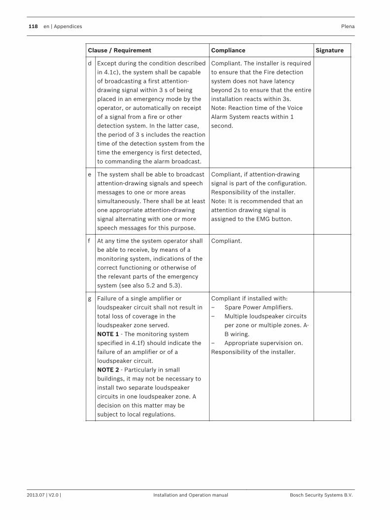
Clause / Requirement Compliance Signature
d Except during the condition describedin 4.1c), the system shall be capableof broadcasting a first attention-drawing signal within 3 s of beingplaced in an emergency mode by theoperator, or automatically on receiptof a signal from a fire or otherdetection system. In the latter case,the period of 3 s includes the reactiontime of the detection system from thetime the emergency is first detected,to commanding the alarm broadcast.
Compliant. The installer is requiredto ensure that the Fire detectionsystem does not have latencybeyond 2s to ensure that the entireinstallation reacts within 3s.Note: Reaction time of the VoiceAlarm System reacts within 1second.
e The system shall be able to broadcastattention-drawing signals and speechmessages to one or more areassimultaneously. There shall be at leastone appropriate attention-drawingsignal alternating with one or morespeech messages for this purpose.
Compliant, if attention-drawingsignal is part of the configuration.Responsibility of the installer.Note: It is recommended that anattention drawing signal isassigned to the EMG button.
f At any time the system operator shallbe able to receive, by means of amonitoring system, indications of thecorrect functioning or otherwise ofthe relevant parts of the emergencysystem (see also 5.2 and 5.3).
Compliant.
g Failure of a single amplifier orloudspeaker circuit shall not result intotal loss of coverage in theloudspeaker zone served.NOTE 1 - The monitoring systemspecified in 4.1f) should indicate thefailure of an amplifier or of aloudspeaker circuit.NOTE 2 - Particularly in smallbuildings, it may not be necessary toinstall two separate loudspeakercircuits in one loudspeaker zone. Adecision on this matter may besubject to local regulations.
Compliant if installed with:– Spare Power Amplifiers.– Multiple loudspeaker circuits
per zone or multiple zones. A-B wiring.
– Appropriate supervision on.Responsibility of the installer.
118 en | Appendices Plena
2013.07 | V2.0 | Installation and Operation manual Bosch Security Systems B.V.
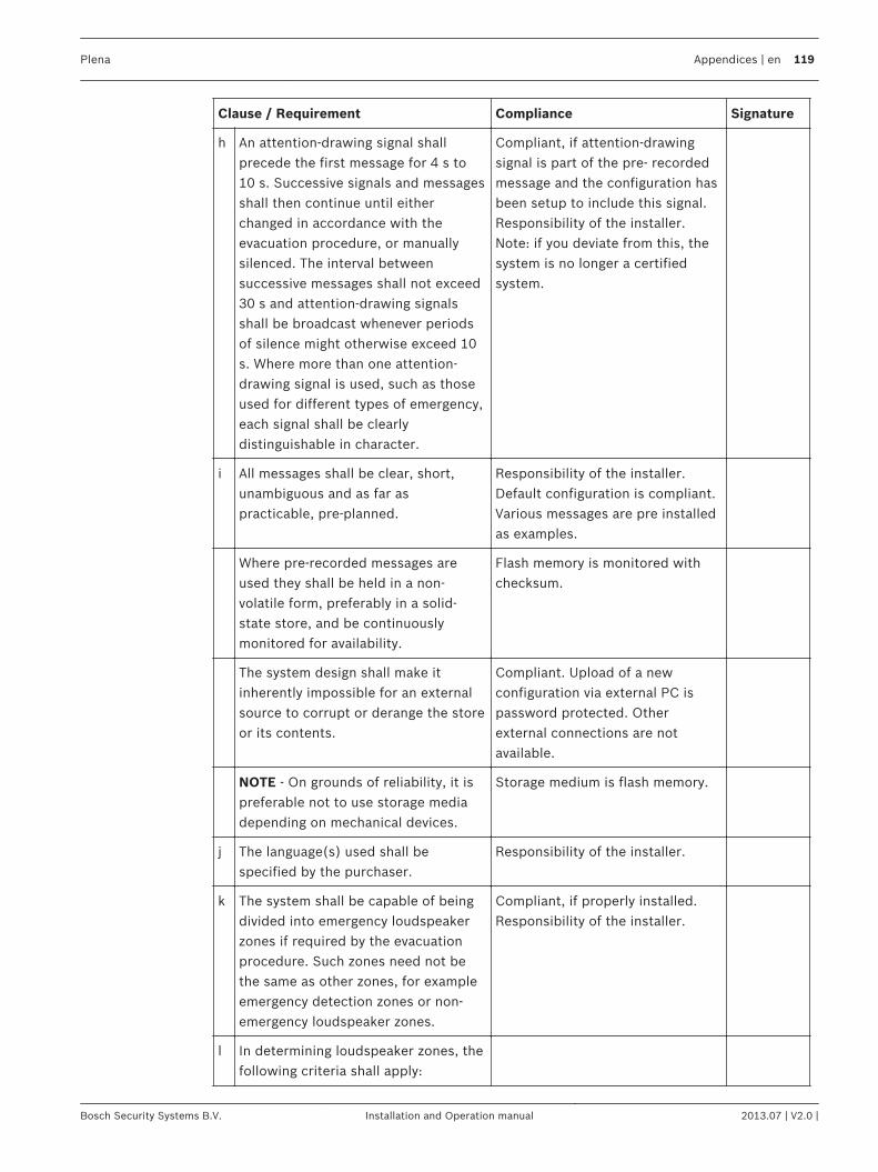
Clause / Requirement Compliance Signature
h An attention-drawing signal shallprecede the first message for 4 s to10 s. Successive signals and messagesshall then continue until eitherchanged in accordance with theevacuation procedure, or manuallysilenced. The interval betweensuccessive messages shall not exceed30 s and attention-drawing signalsshall be broadcast whenever periodsof silence might otherwise exceed 10s. Where more than one attention-drawing signal is used, such as thoseused for different types of emergency,each signal shall be clearlydistinguishable in character.
Compliant, if attention-drawingsignal is part of the pre- recordedmessage and the configuration hasbeen setup to include this signal.Responsibility of the installer.Note: if you deviate from this, thesystem is no longer a certifiedsystem.
i All messages shall be clear, short,unambiguous and as far aspracticable, pre-planned.
Responsibility of the installer.Default configuration is compliant.Various messages are pre installedas examples.
Where pre-recorded messages areused they shall be held in a non-volatile form, preferably in a solid-state store, and be continuouslymonitored for availability.
Flash memory is monitored withchecksum.
The system design shall make itinherently impossible for an externalsource to corrupt or derange the storeor its contents.
Compliant. Upload of a newconfiguration via external PC ispassword protected. Otherexternal connections are notavailable.
NOTE - On grounds of reliability, it ispreferable not to use storage mediadepending on mechanical devices.
Storage medium is flash memory.
j The language(s) used shall bespecified by the purchaser.
Responsibility of the installer.
k The system shall be capable of beingdivided into emergency loudspeakerzones if required by the evacuationprocedure. Such zones need not bethe same as other zones, for exampleemergency detection zones or non-emergency loudspeaker zones.
Compliant, if properly installed.Responsibility of the installer.
l In determining loudspeaker zones, thefollowing criteria shall apply:
Plena Appendices | en 119
Bosch Security Systems B.V. Installation and Operation manual 2013.07 | V2.0 |
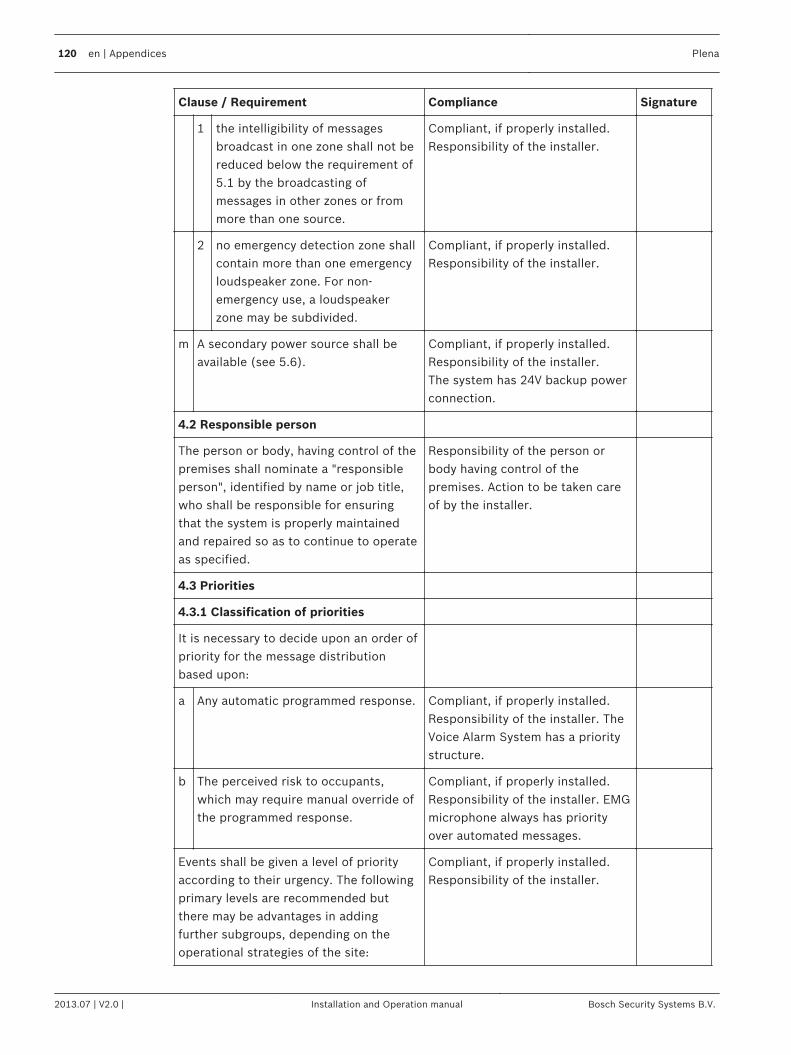
Clause / Requirement Compliance Signature
1 the intelligibility of messagesbroadcast in one zone shall not bereduced below the requirement of5.1 by the broadcasting ofmessages in other zones or frommore than one source.
Compliant, if properly installed.Responsibility of the installer.
2 no emergency detection zone shallcontain more than one emergencyloudspeaker zone. For non-emergency use, a loudspeakerzone may be subdivided.
Compliant, if properly installed.Responsibility of the installer.
m A secondary power source shall beavailable (see 5.6).
Compliant, if properly installed.Responsibility of the installer.The system has 24V backup powerconnection.
4.2 Responsible person
The person or body, having control of thepremises shall nominate a "responsibleperson", identified by name or job title,who shall be responsible for ensuringthat the system is properly maintainedand repaired so as to continue to operateas specified.
Responsibility of the person orbody having control of thepremises. Action to be taken careof by the installer.
4.3 Priorities
4.3.1 Classification of priorities
It is necessary to decide upon an order ofpriority for the message distributionbased upon:
a Any automatic programmed response. Compliant, if properly installed.Responsibility of the installer. TheVoice Alarm System has a prioritystructure.
b The perceived risk to occupants,which may require manual override ofthe programmed response.
Compliant, if properly installed.Responsibility of the installer. EMGmicrophone always has priorityover automated messages.
Events shall be given a level of priorityaccording to their urgency. The followingprimary levels are recommended butthere may be advantages in addingfurther subgroups, depending on theoperational strategies of the site:
Compliant, if properly installed.Responsibility of the installer.
120 en | Appendices Plena
2013.07 | V2.0 | Installation and Operation manual Bosch Security Systems B.V.
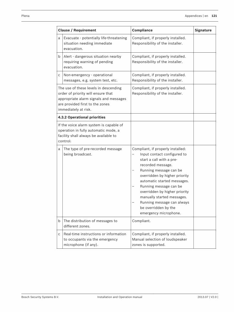
Clause / Requirement Compliance Signature
a Evacuate - potentially life-threateningsituation needing immediateevacuation.
Compliant, if properly installed.Responsibility of the installer.
b Alert - dangerous situation nearbyrequiring warning of pendingevacuation.
Compliant, if properly installed.Responsibility of the installer.
c Non-emergency - operationalmessages, e.g. system test, etc.
Compliant, if properly installed.Responsibility of the installer.
The use of these levels in descendingorder of priority will ensure thatappropriate alarm signals and messagesare provided first to the zonesimmediately at risk.
Compliant, if properly installed.Responsibility of the installer.
4.3.2 Operational priorities
If the voice alarm system is capable ofoperation in fully automatic mode, afacility shall always be available tocontrol:
a The type of pre-recorded messagebeing broadcast.
Compliant, if properly installed:– Input contact configured to
start a call with a pre-recorded message.
– Running message can beoverridden by higher priorityautomatic started messages.
– Running message can beoverridden by higher prioritymanually started messages.
– Running message can alwaysbe overridden by theemergency microphone.
b The distribution of messages todifferent zones.
Compliant.
c Real-time instructions or informationto occupants via the emergencymicrophone (if any).
Compliant, if properly installed.Manual selection of loudspeakerzones is supported.
Plena Appendices | en 121
Bosch Security Systems B.V. Installation and Operation manual 2013.07 | V2.0 |
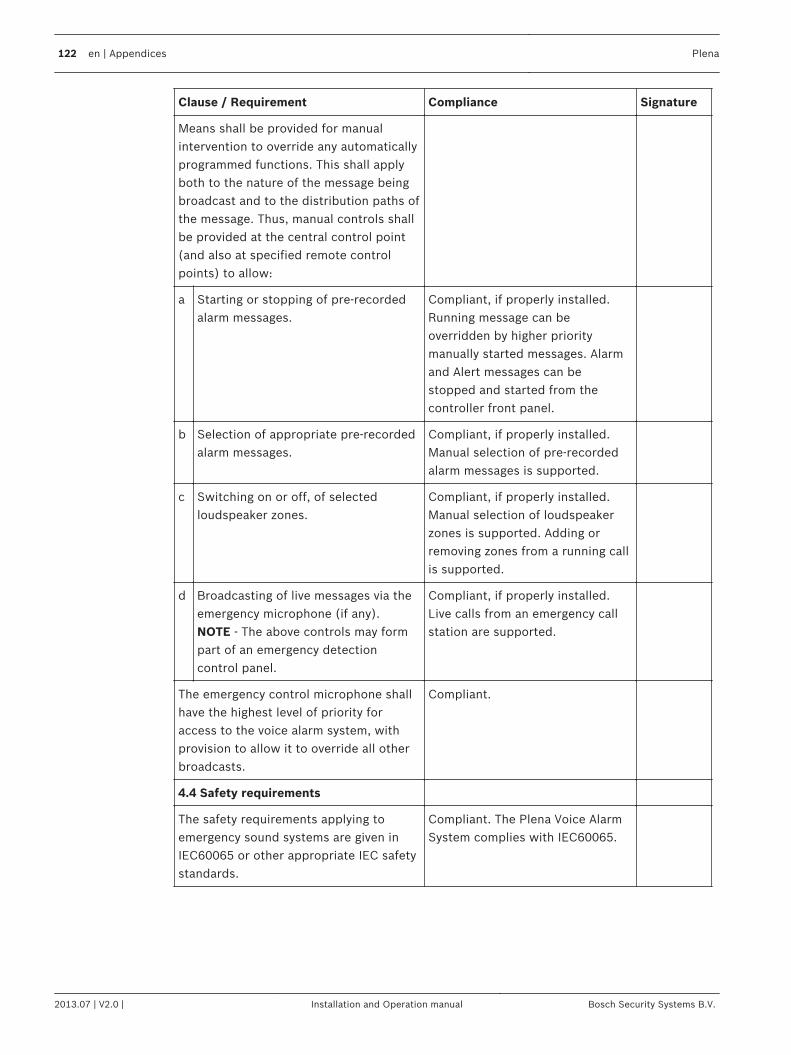
Clause / Requirement Compliance Signature
Means shall be provided for manualintervention to override any automaticallyprogrammed functions. This shall applyboth to the nature of the message beingbroadcast and to the distribution paths ofthe message. Thus, manual controls shallbe provided at the central control point(and also at specified remote controlpoints) to allow:
a Starting or stopping of pre-recordedalarm messages.
Compliant, if properly installed.Running message can beoverridden by higher prioritymanually started messages. Alarmand Alert messages can bestopped and started from thecontroller front panel.
b Selection of appropriate pre-recordedalarm messages.
Compliant, if properly installed.Manual selection of pre-recordedalarm messages is supported.
c Switching on or off, of selectedloudspeaker zones.
Compliant, if properly installed.Manual selection of loudspeakerzones is supported. Adding orremoving zones from a running callis supported.
d Broadcasting of live messages via theemergency microphone (if any).NOTE - The above controls may formpart of an emergency detectioncontrol panel.
Compliant, if properly installed.Live calls from an emergency callstation are supported.
The emergency control microphone shallhave the highest level of priority foraccess to the voice alarm system, withprovision to allow it to override all otherbroadcasts.
Compliant.
4.4 Safety requirements
The safety requirements applying toemergency sound systems are given inIEC60065 or other appropriate IEC safetystandards.
Compliant. The Plena Voice AlarmSystem complies with IEC60065.
122 en | Appendices Plena
2013.07 | V2.0 | Installation and Operation manual Bosch Security Systems B.V.
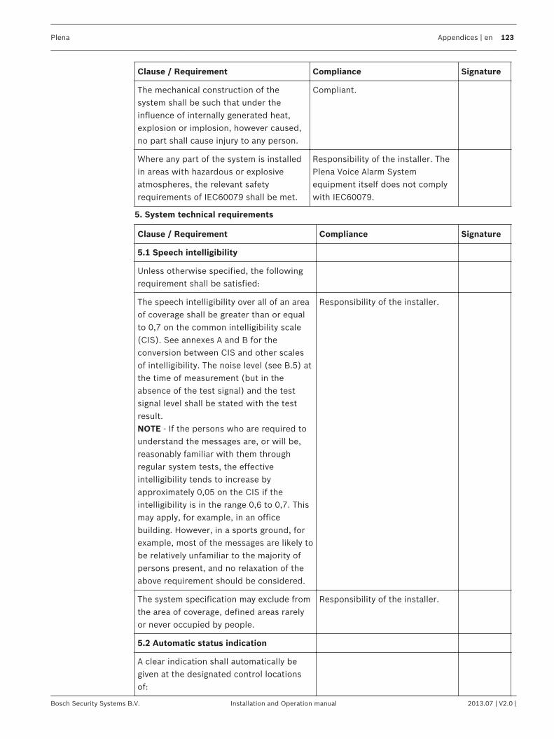
Clause / Requirement Compliance Signature
The mechanical construction of thesystem shall be such that under theinfluence of internally generated heat,explosion or implosion, however caused,no part shall cause injury to any person.
Compliant.
Where any part of the system is installedin areas with hazardous or explosiveatmospheres, the relevant safetyrequirements of IEC60079 shall be met.
Responsibility of the installer. ThePlena Voice Alarm Systemequipment itself does not complywith IEC60079.
5. System technical requirements
Clause / Requirement Compliance Signature
5.1 Speech intelligibility
Unless otherwise specified, the followingrequirement shall be satisfied:
The speech intelligibility over all of an areaof coverage shall be greater than or equalto 0,7 on the common intelligibility scale(CIS). See annexes A and B for theconversion between CIS and other scalesof intelligibility. The noise level (see B.5) atthe time of measurement (but in theabsence of the test signal) and the testsignal level shall be stated with the testresult.NOTE - If the persons who are required tounderstand the messages are, or will be,reasonably familiar with them throughregular system tests, the effectiveintelligibility tends to increase byapproximately 0,05 on the CIS if theintelligibility is in the range 0,6 to 0,7. Thismay apply, for example, in an officebuilding. However, in a sports ground, forexample, most of the messages are likely tobe relatively unfamiliar to the majority ofpersons present, and no relaxation of theabove requirement should be considered.
Responsibility of the installer.
The system specification may exclude fromthe area of coverage, defined areas rarelyor never occupied by people.
Responsibility of the installer.
5.2 Automatic status indication
A clear indication shall automatically begiven at the designated control locationsof:
Plena Appendices | en 123
Bosch Security Systems B.V. Installation and Operation manual 2013.07 | V2.0 |
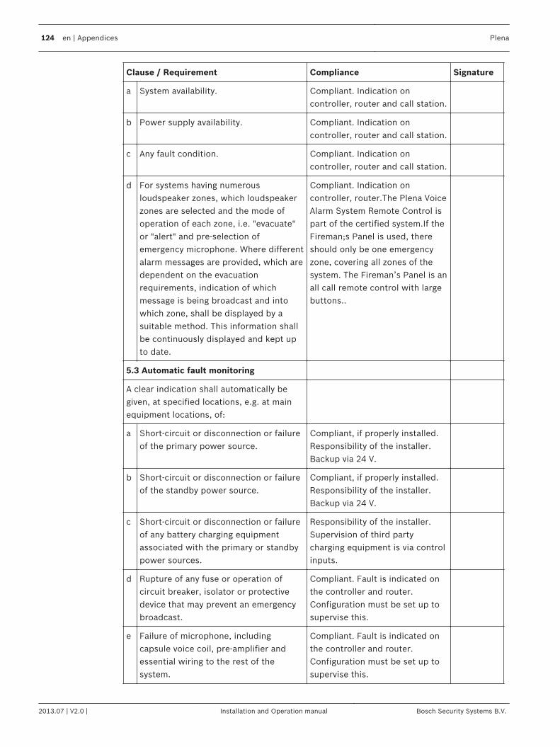
Clause / Requirement Compliance Signature
a System availability. Compliant. Indication oncontroller, router and call station.
b Power supply availability. Compliant. Indication oncontroller, router and call station.
c Any fault condition. Compliant. Indication oncontroller, router and call station.
d For systems having numerousloudspeaker zones, which loudspeakerzones are selected and the mode ofoperation of each zone, i.e. "evacuate"or "alert" and pre-selection ofemergency microphone. Where differentalarm messages are provided, which aredependent on the evacuationrequirements, indication of whichmessage is being broadcast and intowhich zone, shall be displayed by asuitable method. This information shallbe continuously displayed and kept upto date.
Compliant. Indication oncontroller, router.The Plena VoiceAlarm System Remote Control ispart of the certified system.If theFireman;s Panel is used, thereshould only be one emergencyzone, covering all zones of thesystem. The Fireman’s Panel is anall call remote control with largebuttons..
5.3 Automatic fault monitoring
A clear indication shall automatically begiven, at specified locations, e.g. at mainequipment locations, of:
a Short-circuit or disconnection or failureof the primary power source.
Compliant, if properly installed.Responsibility of the installer.Backup via 24 V.
b Short-circuit or disconnection or failureof the standby power source.
Compliant, if properly installed.Responsibility of the installer.Backup via 24 V.
c Short-circuit or disconnection or failureof any battery charging equipmentassociated with the primary or standbypower sources.
Responsibility of the installer.Supervision of third partycharging equipment is via controlinputs.
d Rupture of any fuse or operation ofcircuit breaker, isolator or protectivedevice that may prevent an emergencybroadcast.
Compliant. Fault is indicated onthe controller and router.Configuration must be set up tosupervise this.
e Failure of microphone, includingcapsule voice coil, pre-amplifier andessential wiring to the rest of thesystem.
Compliant. Fault is indicated onthe controller and router.Configuration must be set up tosupervise this.
124 en | Appendices Plena
2013.07 | V2.0 | Installation and Operation manual Bosch Security Systems B.V.
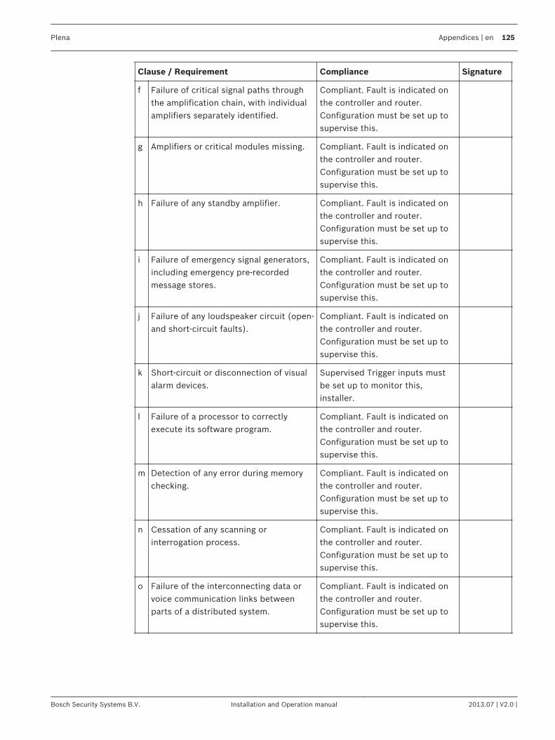
Clause / Requirement Compliance Signature
f Failure of critical signal paths throughthe amplification chain, with individualamplifiers separately identified.
Compliant. Fault is indicated onthe controller and router.Configuration must be set up tosupervise this.
g Amplifiers or critical modules missing. Compliant. Fault is indicated onthe controller and router.Configuration must be set up tosupervise this.
h Failure of any standby amplifier. Compliant. Fault is indicated onthe controller and router.Configuration must be set up tosupervise this.
i Failure of emergency signal generators,including emergency pre-recordedmessage stores.
Compliant. Fault is indicated onthe controller and router.Configuration must be set up tosupervise this.
j Failure of any loudspeaker circuit (open-and short-circuit faults).
Compliant. Fault is indicated onthe controller and router.Configuration must be set up tosupervise this.
k Short-circuit or disconnection of visualalarm devices.
Supervised Trigger inputs mustbe set up to monitor this,installer.
l Failure of a processor to correctlyexecute its software program.
Compliant. Fault is indicated onthe controller and router.Configuration must be set up tosupervise this.
m Detection of any error during memorychecking.
Compliant. Fault is indicated onthe controller and router.Configuration must be set up tosupervise this.
n Cessation of any scanning orinterrogation process.
Compliant. Fault is indicated onthe controller and router.Configuration must be set up tosupervise this.
o Failure of the interconnecting data orvoice communication links betweenparts of a distributed system.
Compliant. Fault is indicated onthe controller and router.Configuration must be set up tosupervise this.
Plena Appendices | en 125
Bosch Security Systems B.V. Installation and Operation manual 2013.07 | V2.0 |
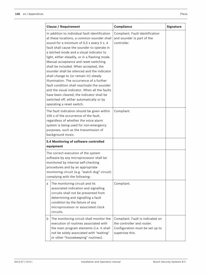
Clause / Requirement Compliance Signature
In addition to individual fault identificationat these locations, a common sounder shallsound for a minimum of 0,5 s every 5 s. Afault shall cause the sounder to operate ina latched mode and a visual indicator tolight, either steadily, or in a flashing mode.Manual acceptance and reset switchingshall be included. When accepted, thesounder shall be silenced and the indicatorshall change to (or remain in) steadyillumination. The occurrence of a furtherfault condition shall reactivate the sounderand the visual indicator. When all the faultshave been cleared, the indicator shall beswitched off, either automatically or byoperating a reset switch.
Compliant. Fault identificationand sounder is part of thecontroller.
The fault indication should be given within100 s of the occurrence of the fault,regardless of whether the voice alarmsystem is being used for non-emergencypurposes, such as the transmission ofbackground music.
Compliant.
5.4 Monitoring of software controlledequipment
The correct execution of the systemsoftware by any microprocessor shall bemonitored by internal self-checkingprocedures and by an appropriatemonitoring circuit (e.g. "watch dog" circuit)complying with the following:
a The monitoring circuit and itsassociated indication and signallingcircuits shall not be prevented fromdetermining and signalling a faultcondition by the failure of anymicroprocessor or associated clockcircuits.
Compliant.
b The monitoring circuit shall monitor theexecution of routines associated withthe main program elements (i.e. it shallnot be solely associated with "waiting"or other "housekeeping" routines).
Compliant. Fault is indicated onthe controller and router.Configuration must be set up tosupervise this.
126 en | Appendices Plena
2013.07 | V2.0 | Installation and Operation manual Bosch Security Systems B.V.
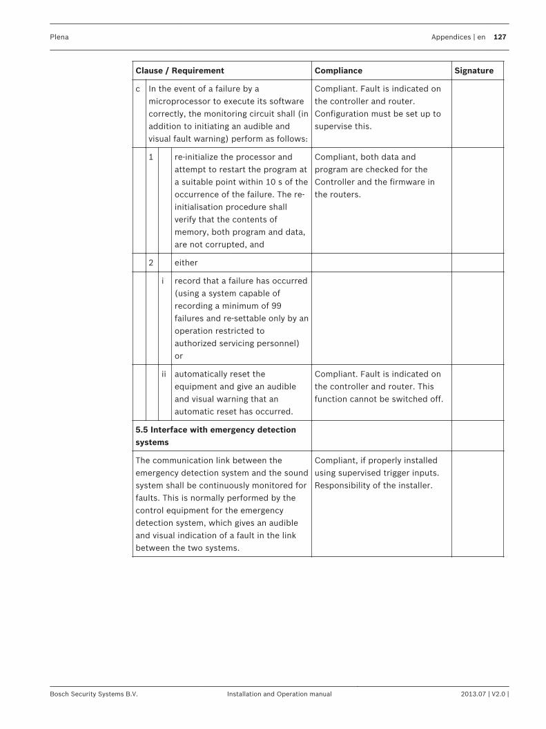
Clause / Requirement Compliance Signature
c In the event of a failure by amicroprocessor to execute its softwarecorrectly, the monitoring circuit shall (inaddition to initiating an audible andvisual fault warning) perform as follows:
Compliant. Fault is indicated onthe controller and router.Configuration must be set up tosupervise this.
1 re-initialize the processor andattempt to restart the program ata suitable point within 10 s of theoccurrence of the failure. The re-initialisation procedure shallverify that the contents ofmemory, both program and data,are not corrupted, and
Compliant, both data andprogram are checked for theController and the firmware inthe routers.
2 either
i record that a failure has occurred(using a system capable ofrecording a minimum of 99failures and re-settable only by anoperation restricted toauthorized servicing personnel)or
ii automatically reset theequipment and give an audibleand visual warning that anautomatic reset has occurred.
Compliant. Fault is indicated onthe controller and router. Thisfunction cannot be switched off.
5.5 Interface with emergency detectionsystems
The communication link between theemergency detection system and the soundsystem shall be continuously monitored forfaults. This is normally performed by thecontrol equipment for the emergencydetection system, which gives an audibleand visual indication of a fault in the linkbetween the two systems.
Compliant, if properly installedusing supervised trigger inputs.Responsibility of the installer.
Plena Appendices | en 127
Bosch Security Systems B.V. Installation and Operation manual 2013.07 | V2.0 |
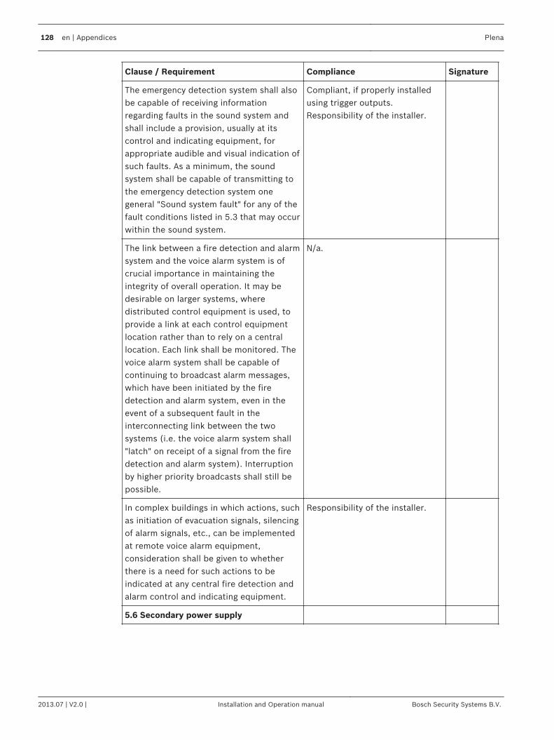
Clause / Requirement Compliance Signature
The emergency detection system shall alsobe capable of receiving informationregarding faults in the sound system andshall include a provision, usually at itscontrol and indicating equipment, forappropriate audible and visual indication ofsuch faults. As a minimum, the soundsystem shall be capable of transmitting tothe emergency detection system onegeneral "Sound system fault" for any of thefault conditions listed in 5.3 that may occurwithin the sound system.
Compliant, if properly installedusing trigger outputs.Responsibility of the installer.
The link between a fire detection and alarmsystem and the voice alarm system is ofcrucial importance in maintaining theintegrity of overall operation. It may bedesirable on larger systems, wheredistributed control equipment is used, toprovide a link at each control equipmentlocation rather than to rely on a centrallocation. Each link shall be monitored. Thevoice alarm system shall be capable ofcontinuing to broadcast alarm messages,which have been initiated by the firedetection and alarm system, even in theevent of a subsequent fault in theinterconnecting link between the twosystems (i.e. the voice alarm system shall"latch" on receipt of a signal from the firedetection and alarm system). Interruptionby higher priority broadcasts shall still bepossible.
N/a.
In complex buildings in which actions, suchas initiation of evacuation signals, silencingof alarm signals, etc., can be implementedat remote voice alarm equipment,consideration shall be given to whetherthere is a need for such actions to beindicated at any central fire detection andalarm control and indicating equipment.
Responsibility of the installer.
5.6 Secondary power supply
128 en | Appendices Plena
2013.07 | V2.0 | Installation and Operation manual Bosch Security Systems B.V.
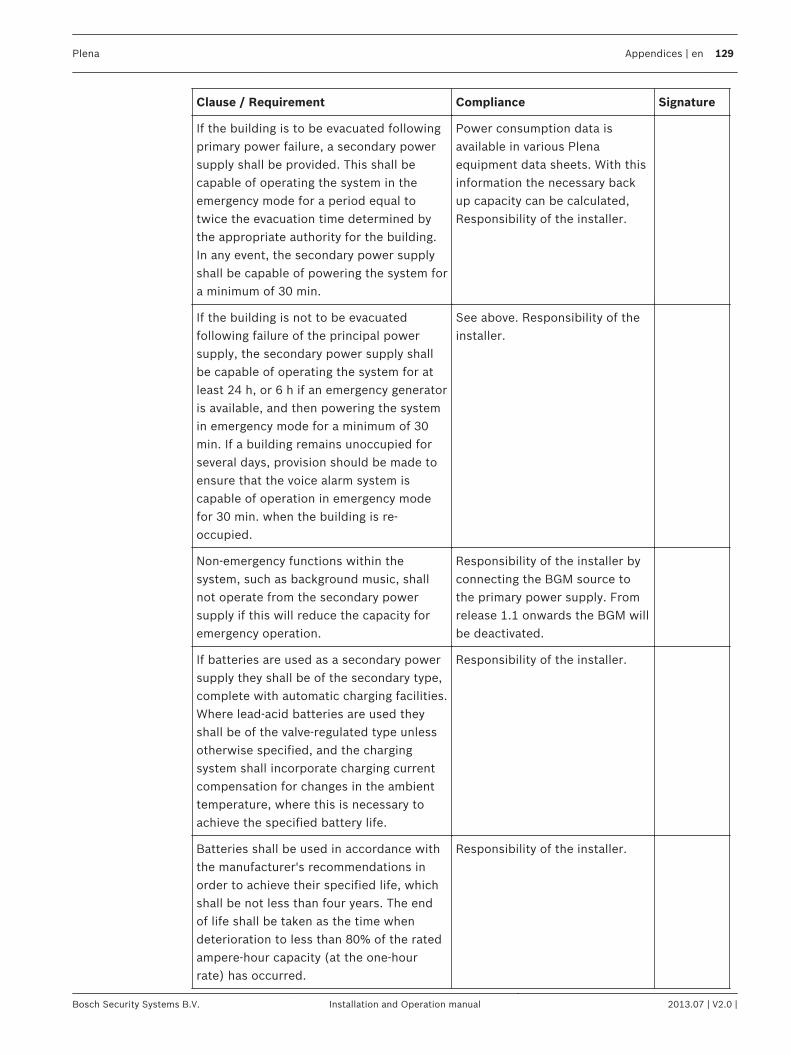
Clause / Requirement Compliance Signature
If the building is to be evacuated followingprimary power failure, a secondary powersupply shall be provided. This shall becapable of operating the system in theemergency mode for a period equal totwice the evacuation time determined bythe appropriate authority for the building.In any event, the secondary power supplyshall be capable of powering the system fora minimum of 30 min.
Power consumption data isavailable in various Plenaequipment data sheets. With thisinformation the necessary backup capacity can be calculated,Responsibility of the installer.
If the building is not to be evacuatedfollowing failure of the principal powersupply, the secondary power supply shallbe capable of operating the system for atleast 24 h, or 6 h if an emergency generatoris available, and then powering the systemin emergency mode for a minimum of 30min. If a building remains unoccupied forseveral days, provision should be made toensure that the voice alarm system iscapable of operation in emergency modefor 30 min. when the building is re-occupied.
See above. Responsibility of theinstaller.
Non-emergency functions within thesystem, such as background music, shallnot operate from the secondary powersupply if this will reduce the capacity foremergency operation.
Responsibility of the installer byconnecting the BGM source tothe primary power supply. Fromrelease 1.1 onwards the BGM willbe deactivated.
If batteries are used as a secondary powersupply they shall be of the secondary type,complete with automatic charging facilities.Where lead-acid batteries are used theyshall be of the valve-regulated type unlessotherwise specified, and the chargingsystem shall incorporate charging currentcompensation for changes in the ambienttemperature, where this is necessary toachieve the specified battery life.
Responsibility of the installer.
Batteries shall be used in accordance withthe manufacturer's recommendations inorder to achieve their specified life, whichshall be not less than four years. The endof life shall be taken as the time whendeterioration to less than 80% of the ratedampere-hour capacity (at the one-hourrate) has occurred.
Responsibility of the installer.
Plena Appendices | en 129
Bosch Security Systems B.V. Installation and Operation manual 2013.07 | V2.0 |
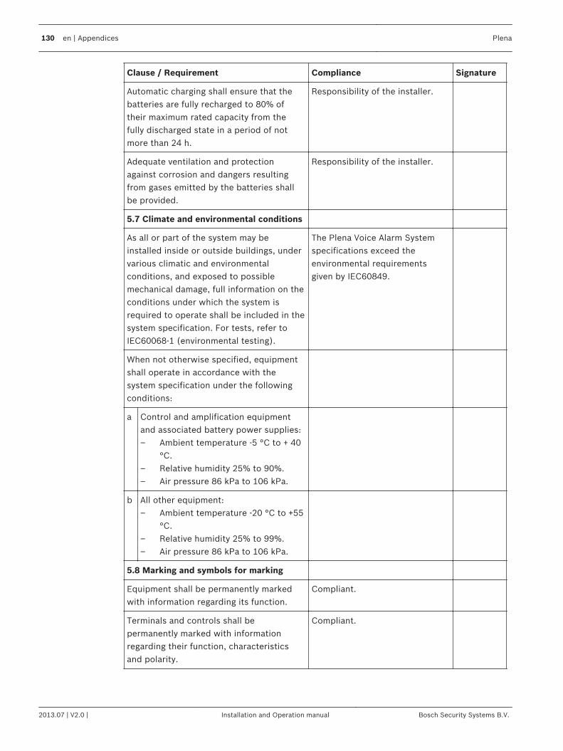
Clause / Requirement Compliance Signature
Automatic charging shall ensure that thebatteries are fully recharged to 80% oftheir maximum rated capacity from thefully discharged state in a period of notmore than 24 h.
Responsibility of the installer.
Adequate ventilation and protectionagainst corrosion and dangers resultingfrom gases emitted by the batteries shallbe provided.
Responsibility of the installer.
5.7 Climate and environmental conditions
As all or part of the system may beinstalled inside or outside buildings, undervarious climatic and environmentalconditions, and exposed to possiblemechanical damage, full information on theconditions under which the system isrequired to operate shall be included in thesystem specification. For tests, refer toIEC60068-1 (environmental testing).
The Plena Voice Alarm Systemspecifications exceed theenvironmental requirementsgiven by IEC60849.
When not otherwise specified, equipmentshall operate in accordance with thesystem specification under the followingconditions:
a Control and amplification equipmentand associated battery power supplies:– Ambient temperature -5 °C to + 40
°C.– Relative humidity 25% to 90%.– Air pressure 86 kPa to 106 kPa.
b All other equipment:– Ambient temperature -20 °C to +55
°C.– Relative humidity 25% to 99%.– Air pressure 86 kPa to 106 kPa.
5.8 Marking and symbols for marking
Equipment shall be permanently markedwith information regarding its function.
Compliant.
Terminals and controls shall bepermanently marked with informationregarding their function, characteristicsand polarity.
Compliant.
130 en | Appendices Plena
2013.07 | V2.0 | Installation and Operation manual Bosch Security Systems B.V.
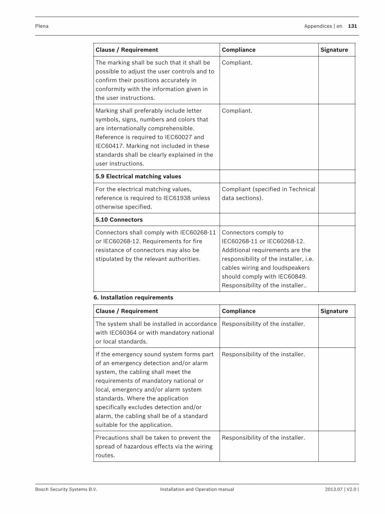
Clause / Requirement Compliance Signature
The marking shall be such that it shall bepossible to adjust the user controls and toconfirm their positions accurately inconformity with the information given inthe user instructions.
Compliant.
Marking shall preferably include lettersymbols, signs, numbers and colors thatare internationally comprehensible.Reference is required to IEC60027 andIEC60417. Marking not included in thesestandards shall be clearly explained in theuser instructions.
Compliant.
5.9 Electrical matching values
For the electrical matching values,reference is required to IEC61938 unlessotherwise specified.
Compliant (specified in Technicaldata sections).
5.10 Connectors
Connectors shall comply with IEC60268-11or IEC60268-12. Requirements for fireresistance of connectors may also bestipulated by the relevant authorities.
Connectors comply toIEC60268-11 or IEC60268-12.Additional requirements are theresponsibility of the installer, i.e.cables wiring and loudspeakersshould comply with IEC60849.Responsibility of the installer..
6. Installation requirements
Clause / Requirement Compliance Signature
The system shall be installed in accordancewith IEC60364 or with mandatory nationalor local standards.
Responsibility of the installer.
If the emergency sound system forms partof an emergency detection and/or alarmsystem, the cabling shall meet therequirements of mandatory national orlocal, emergency and/or alarm systemstandards. Where the applicationspecifically excludes detection and/oralarm, the cabling shall be of a standardsuitable for the application.
Responsibility of the installer.
Precautions shall be taken to prevent thespread of hazardous effects via the wiringroutes.
Responsibility of the installer.
Plena Appendices | en 131
Bosch Security Systems B.V. Installation and Operation manual 2013.07 | V2.0 |
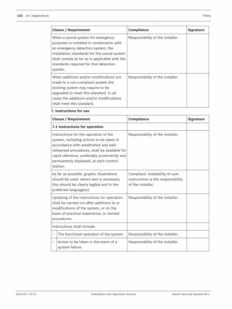
Clause / Requirement Compliance Signature
When a sound system for emergencypurposes is installed in combination withan emergency detection system, theinstallation standards for the sound systemshall comply as far as is applicable with thestandards required for that detectionsystem.
Responsibility of the installer.
When additions and/or modifications aremade to a non-compliant system theexisting system may require to beupgraded to meet this standard. In allcases the additions and/or modificationsshall meet this standard.
Responsibility of the installer.
7. Instructions for use
Clause / Requirement Compliance Signature
7.1 Instructions for operation
Instructions for the operation of thesystem, including actions to be taken inaccordance with established and well-rehearsed procedures, shall be available forrapid reference, preferably prominently andpermanently displayed, at each controlstation.
Responsibility of the installer.
As far as possible, graphic illustrationsshould be used: where text is necessarythis should be clearly legible and in thepreferred language(s).
Compliant. Availability of userinstructions is the responsibilityof the installer.
Updating of the instructions for operationshall be carried out after additions to ormodifications of the system, or on thebasis of practical experience, or revisedprocedures.
Responsibility of the installer.
Instructions shall include:
– The functional operation of the system. Responsibility of the installer.
– Action to be taken in the event of asystem failure.
Responsibility of the installer.
132 en | Appendices Plena
2013.07 | V2.0 | Installation and Operation manual Bosch Security Systems B.V.
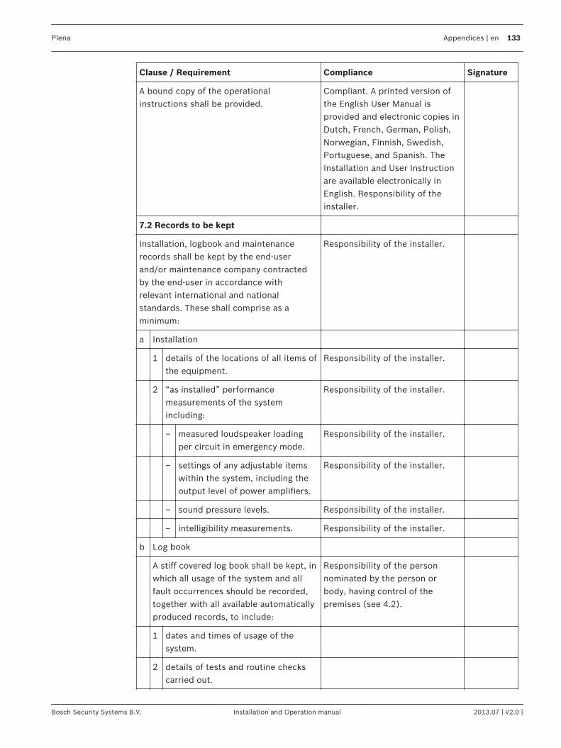
Clause / Requirement Compliance Signature
A bound copy of the operationalinstructions shall be provided.
Compliant. A printed version ofthe English User Manual isprovided and electronic copies inDutch, French, German, Polish,Norwegian, Finnish, Swedish,Portuguese, and Spanish. TheInstallation and User Instructionare available electronically inEnglish. Responsibility of theinstaller.
7.2 Records to be kept
Installation, logbook and maintenancerecords shall be kept by the end-userand/or maintenance company contractedby the end-user in accordance withrelevant international and nationalstandards. These shall comprise as aminimum:
Responsibility of the installer.
a Installation
1 details of the locations of all items ofthe equipment.
Responsibility of the installer.
2 “as installed” performancemeasurements of the systemincluding:
Responsibility of the installer.
– measured loudspeaker loadingper circuit in emergency mode.
Responsibility of the installer.
– settings of any adjustable itemswithin the system, including theoutput level of power amplifiers.
Responsibility of the installer.
– sound pressure levels. Responsibility of the installer.
– intelligibility measurements. Responsibility of the installer.
b Log book
A stiff covered log book shall be kept, inwhich all usage of the system and allfault occurrences should be recorded,together with all available automaticallyproduced records, to include:
Responsibility of the personnominated by the person orbody, having control of thepremises (see 4.2).
1 dates and times of usage of thesystem.
2 details of tests and routine checkscarried out.
Plena Appendices | en 133
Bosch Security Systems B.V. Installation and Operation manual 2013.07 | V2.0 |
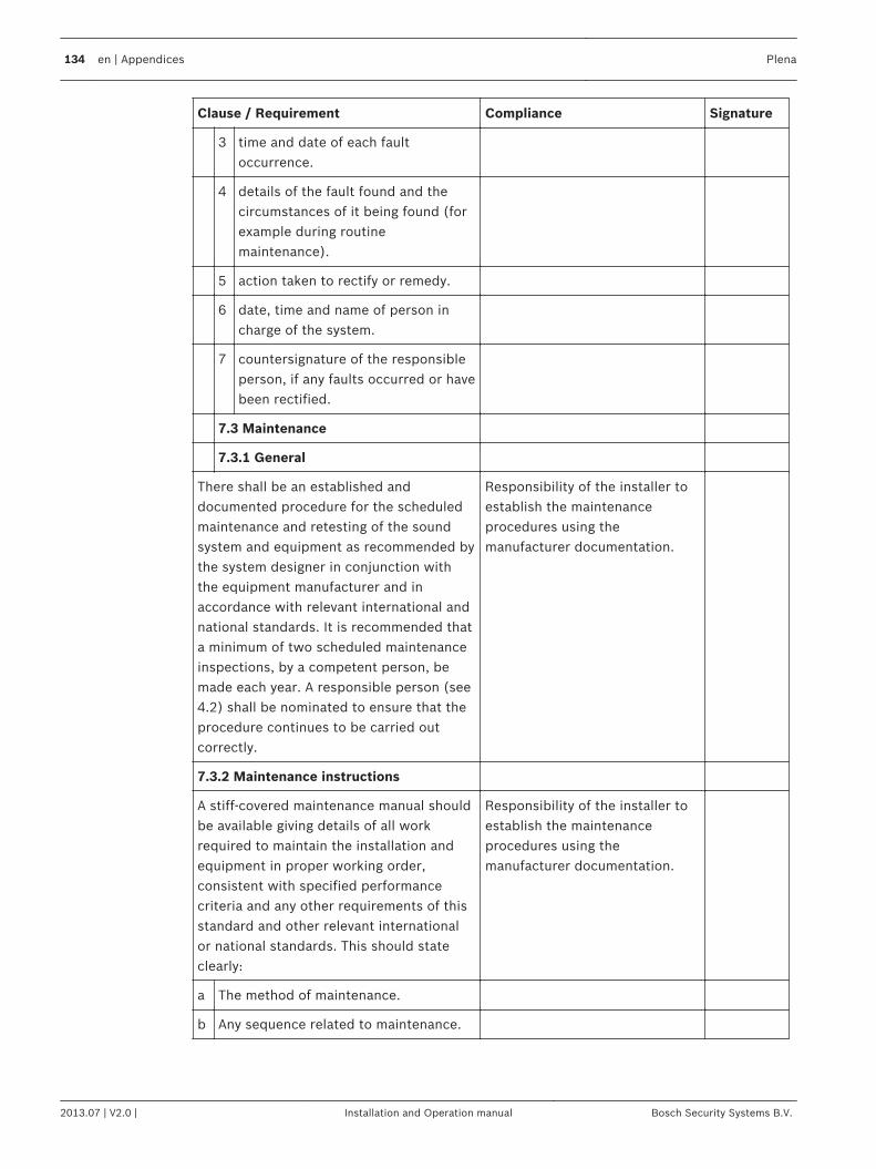
Clause / Requirement Compliance Signature
3 time and date of each faultoccurrence.
4 details of the fault found and thecircumstances of it being found (forexample during routinemaintenance).
5 action taken to rectify or remedy.
6 date, time and name of person incharge of the system.
7 countersignature of the responsibleperson, if any faults occurred or havebeen rectified.
7.3 Maintenance
7.3.1 General
There shall be an established anddocumented procedure for the scheduledmaintenance and retesting of the soundsystem and equipment as recommended bythe system designer in conjunction withthe equipment manufacturer and inaccordance with relevant international andnational standards. It is recommended thata minimum of two scheduled maintenanceinspections, by a competent person, bemade each year. A responsible person (see4.2) shall be nominated to ensure that theprocedure continues to be carried outcorrectly.
Responsibility of the installer toestablish the maintenanceprocedures using themanufacturer documentation.
7.3.2 Maintenance instructions
A stiff-covered maintenance manual shouldbe available giving details of all workrequired to maintain the installation andequipment in proper working order,consistent with specified performancecriteria and any other requirements of thisstandard and other relevant internationalor national standards. This should stateclearly:
Responsibility of the installer toestablish the maintenanceprocedures using themanufacturer documentation.
a The method of maintenance.
b Any sequence related to maintenance.
134 en | Appendices Plena
2013.07 | V2.0 | Installation and Operation manual Bosch Security Systems B.V.
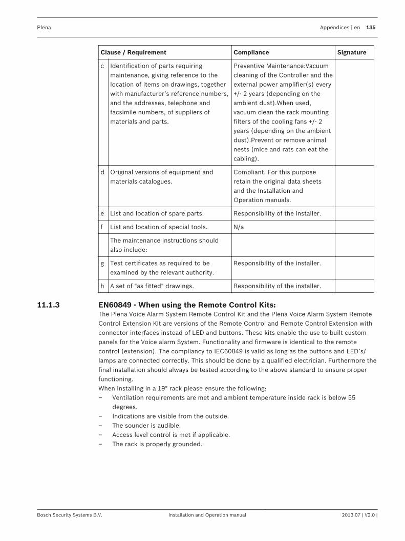
Clause / Requirement Compliance Signature
c Identification of parts requiringmaintenance, giving reference to thelocation of items on drawings, togetherwith manufacturer’s reference numbers,and the addresses, telephone andfacsimile numbers, of suppliers ofmaterials and parts.
Preventive Maintenance:Vacuumcleaning of the Controller and theexternal power amplifier(s) every+/- 2 years (depending on theambient dust).When used,vacuum clean the rack mountingfilters of the cooling fans +/- 2years (depending on the ambientdust).Prevent or remove animalnests (mice and rats can eat thecabling).
d Original versions of equipment andmaterials catalogues.
Compliant. For this purposeretain the original data sheetsand the Installation andOperation manuals.
e List and location of spare parts. Responsibility of the installer.
f List and location of special tools. N/a
The maintenance instructions shouldalso include:
g Test certificates as required to beexamined by the relevant authority.
Responsibility of the installer.
h A set of "as fitted" drawings. Responsibility of the installer.
EN60849 - When using the Remote Control Kits:The Plena Voice Alarm System Remote Control Kit and the Plena Voice Alarm System RemoteControl Extension Kit are versions of the Remote Control and Remote Control Extension withconnector interfaces instead of LED and buttons. These kits enable the use to built custompanels for the Voice alarm System. Functionality and firmware is identical to the remotecontrol (extension). The compliancy to IEC60849 is valid as long as the buttons and LED’s/lamps are connected correctly. This should be done by a qualified electrician. Furthermore thefinal installation should always be tested according to the above standard to ensure properfunctioning.When installing in a 19" rack please ensure the following:– Ventilation requirements are met and ambient temperature inside rack is below 55
degrees.– Indications are visible from the outside.– The sounder is audible.– Access level control is met if applicable.– The rack is properly grounded.
11.1.3
Plena Appendices | en 135
Bosch Security Systems B.V. Installation and Operation manual 2013.07 | V2.0 |
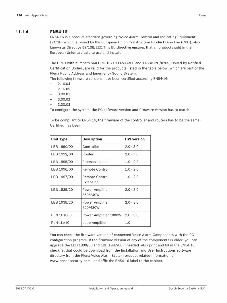
EN54-16EN54‑16 is a product standard governing 'Voice Alarm Control and Indicating Equipment'(VACIE) which is issued by the European Union Construction Product Directive (CPD), alsoknown as Directive 89/106/EEC.This EU directive ensures that all products sold in theEuropean Union are safe to use and install. The CPDs with numbers 560‑CPD‑10219002/AA/00 and 1438/CPD/0209, issued by NotifiedCertification Bodies, are valid for the products listed in the table below, which are part of thePlena Public Address and Emergency Sound System.The following firmware versions have been certified according EN54‑16:– 2.16.04– 2.16.05– 3.00.01– 3.00.02– 3.00.03To configure the system, the PC software version and firmware version has to match. To be compliant to EN54‑16, the firmware of the controller and routers has to be the same.Certified has been:
Unit Type Description HW version
LBB 1990/00 Controller 2.0 - 3.0
LBB 1992/00 Router 2.0 - 3.0
LBB 1995/00 Fireman's panel 1.0 - 2.0
LBB 1996/00 Remote Control 1.0 - 2.0
LBB 1997/00 Remote ControlExtension
1.0 - 2.0
LBB 1935/20 Power Amplifier360/240W
2.0 - 3.0
LBB 1938/20 Power Amplifier720/480W
2.0 - 3.0
PLN-1P1000 Power Amplifier 1000W 2.0 - 3.0
PLN-1LA10 Loop Amplifier 1.0
You can check the firmware version of connected Voice Alarm Components with the PCconfiguration program. If the firmware version of any of the components is older, you canupgrade the LBB 1990/00 and LBB 1992/00 if needed. Also print and fill in the EN54‑16checklist that could be download from the Installation and User Instructions softwaredirectory from the Plena Voice Alarm System product related information onwww.boschsecurity.com , and affix the EN54‑16 label to the cabinet.
11.1.4
136 en | Appendices Plena
2013.07 | V2.0 | Installation and Operation manual Bosch Security Systems B.V.
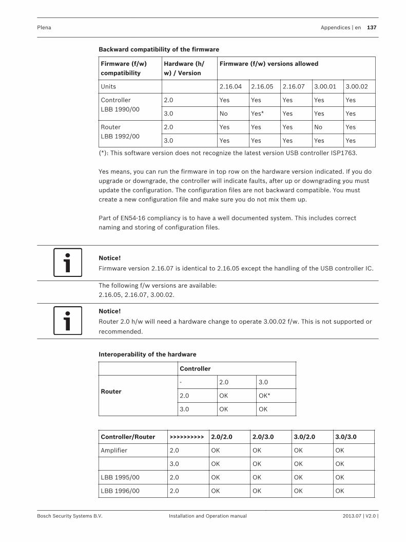
Backward compatibility of the firmware
Firmware (f/w)compatibility
Hardware (h/w) / Version
Firmware (f/w) versions allowed
Units 2.16.04 2.16.05 2.16.07 3.00.01 3.00.02
ControllerLBB 1990/00
2.0 Yes Yes Yes Yes Yes
3.0 No Yes* Yes Yes Yes
RouterLBB 1992/00
2.0 Yes Yes Yes No Yes
3.0 Yes Yes Yes Yes Yes
(*): This software version does not recognize the latest version USB controller ISP1763. Yes means, you can run the firmware in top row on the hardware version indicated. If you doupgrade or downgrade, the controller will indicate faults, after up or downgrading you mustupdate the configuration. The configuration files are not backward compatible. You mustcreate a new configuration file and make sure you do not mix them up. Part of EN54‑16 compliancy is to have a well documented system. This includes correctnaming and storing of configuration files.
Notice!
Firmware version 2.16.07 is identical to 2.16.05 except the handling of the USB controller IC.
The following f/w versions are available:2.16.05, 2.16.07, 3.00.02.
Notice!
Router 2.0 h/w will need a hardware change to operate 3.00.02 f/w. This is not supported or
recommended.
Interoperability of the hardware
Controller
Router
- 2.0 3.0
2.0 OK OK*
3.0 OK OK
Controller/Router >>>>>>>>>> 2.0/2.0 2.0/3.0 3.0/2.0 3.0/3.0
Amplifier 2.0 OK OK OK OK
3.0 OK OK OK OK
LBB 1995/00 2.0 OK OK OK OK
LBB 1996/00 2.0 OK OK OK OK
Plena Appendices | en 137
Bosch Security Systems B.V. Installation and Operation manual 2013.07 | V2.0 |
Controller/Router >>>>>>>>>> 2.0/2.0 2.0/3.0 3.0/2.0 3.0/3.0
LBB 1997/00 2.0 OK OK OK OK
LBB 1998 2.0 OK OK OK OK
LBB 1999 2.0 OK OK OK OK
To use a 3.0 controller with 2.0 routers, you must downgrade the controller to 2.16.05 or2.16.07. You will not have the functionality and bugfixes of 3.00.01 or 3.00.02.You may use 2.0h/w routers on 3.0 controllers with the controller running 3.00.02, as router 1-9. This option isavailable when expanding systems. We recommend that the same h/w version and same f/ware used in one system.We recommend that the leading number matches, so if possible install2.x firmware on 2.x hardware, and only install 3.x f/w on 3.x h/w.
Notice!
For more information, manual addenda and release notes, check the 3.00.xx or 2.16.05 Plena
Voice Alarm System product related information on www.boschsecurity.com.
Notice!
When upgrading the controller firmware from version 2.16.05 to 3.00.0x, the configuration
has to made again in the 3.00.0x PC software and uploaded into the controller again. It is not
possible to load configuration if the PC software version does not match the firmware
version.
Windows 7 compatibilityVersion 3.0 will run on Windows 7 Professional or Ultimate. Be sure that the user has localadmin rights.
138 en | Appendices Plena
2013.07 | V2.0 | Installation and Operation manual Bosch Security Systems B.V.
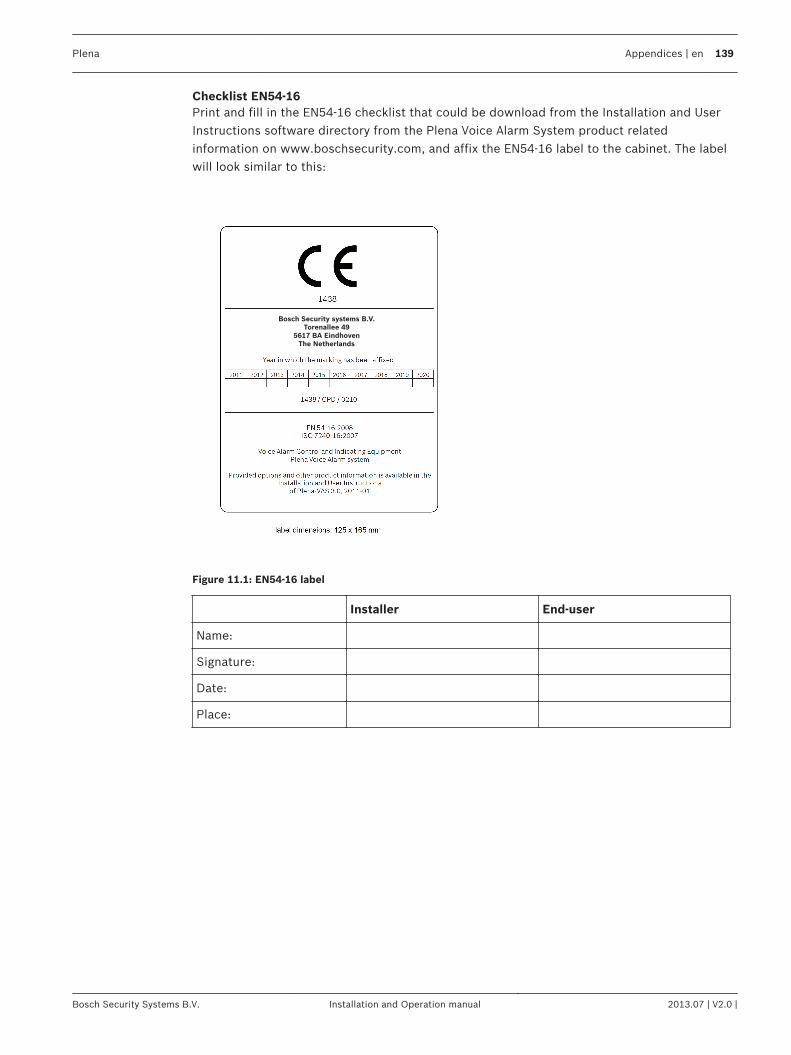
Checklist EN54‑16Print and fill in the EN54‑16 checklist that could be download from the Installation and UserInstructions software directory from the Plena Voice Alarm System product relatedinformation on www.boschsecurity.com, and affix the EN54‑16 label to the cabinet. The labelwill look similar to this:
Bosch Security systems B.V.
Torenallee 49
5617 BA Eindhoven
The Netherlands
Figure 11.1: EN54‑16 label
Installer End-user
Name:
Signature:
Date:
Place:
Plena Appendices | en 139
Bosch Security Systems B.V. Installation and Operation manual 2013.07 | V2.0 |
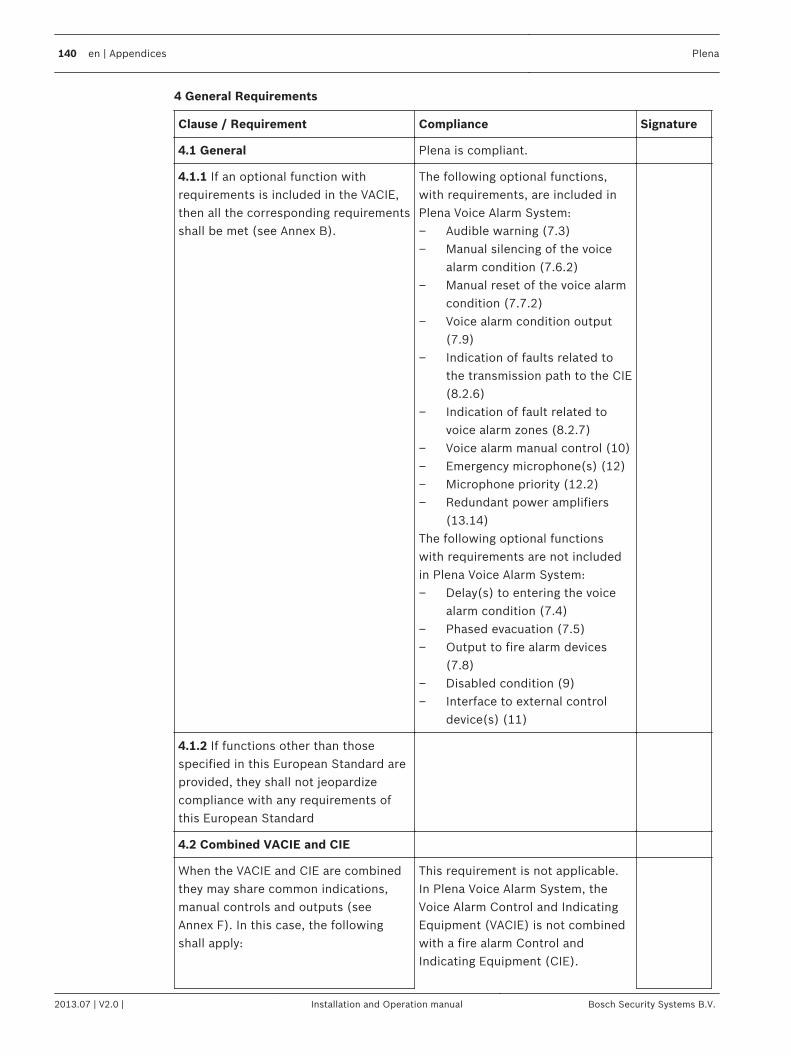
4 General Requirements
Clause / Requirement Compliance Signature
4.1 General Plena is compliant.
4.1.1 If an optional function withrequirements is included in the VACIE,then all the corresponding requirementsshall be met (see Annex B).
The following optional functions,with requirements, are included inPlena Voice Alarm System:– Audible warning (7.3)– Manual silencing of the voice
alarm condition (7.6.2)– Manual reset of the voice alarm
condition (7.7.2)– Voice alarm condition output
(7.9)– Indication of faults related to
the transmission path to the CIE(8.2.6)
– Indication of fault related tovoice alarm zones (8.2.7)
– Voice alarm manual control (10)– Emergency microphone(s) (12)– Microphone priority (12.2)– Redundant power amplifiers
(13.14)The following optional functionswith requirements are not includedin Plena Voice Alarm System:– Delay(s) to entering the voice
alarm condition (7.4)– Phased evacuation (7.5)– Output to fire alarm devices
(7.8)– Disabled condition (9)– Interface to external control
device(s) (11)
4.1.2 If functions other than thosespecified in this European Standard areprovided, they shall not jeopardizecompliance with any requirements ofthis European Standard
4.2 Combined VACIE and CIE
When the VACIE and CIE are combinedthey may share common indications,manual controls and outputs (seeAnnex F). In this case, the followingshall apply:
This requirement is not applicable.In Plena Voice Alarm System, theVoice Alarm Control and IndicatingEquipment (VACIE) is not combinedwith a fire alarm Control andIndicating Equipment (CIE).
140 en | Appendices Plena
2013.07 | V2.0 | Installation and Operation manual Bosch Security Systems B.V.
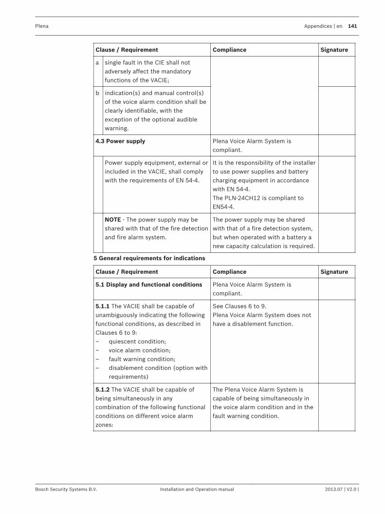
Clause / Requirement Compliance Signature
a single fault in the CIE shall notadversely affect the mandatoryfunctions of the VACIE;
b indication(s) and manual control(s)of the voice alarm condition shall beclearly identifiable, with theexception of the optional audiblewarning.
4.3 Power supply Plena Voice Alarm System iscompliant.
Power supply equipment, external orincluded in the VACIE, shall complywith the requirements of EN 54‑4.
It is the responsibility of the installerto use power supplies and batterycharging equipment in accordancewith EN 54‑4.The PLN‑24CH12 is compliant toEN54‑4.
NOTE - The power supply may beshared with that of the fire detectionand fire alarm system.
The power supply may be sharedwith that of a fire detection system,but when operated with a battery anew capacity calculation is required.
5 General requirements for indications
Clause / Requirement Compliance Signature
5.1 Display and functional conditions Plena Voice Alarm System iscompliant.
5.1.1 The VACIE shall be capable ofunambiguously indicating the followingfunctional conditions, as described inClauses 6 to 9:– quiescent condition;– voice alarm condition;– fault warning condition;– disablement condition (option with
requirements)
See Clauses 6 to 9.Plena Voice Alarm System does nothave a disablement function.
5.1.2 The VACIE shall be capable ofbeing simultaneously in anycombination of the following functionalconditions on different voice alarmzones:
The Plena Voice Alarm System iscapable of being simultaneously inthe voice alarm condition and in thefault warning condition.
Plena Appendices | en 141
Bosch Security Systems B.V. Installation and Operation manual 2013.07 | V2.0 |
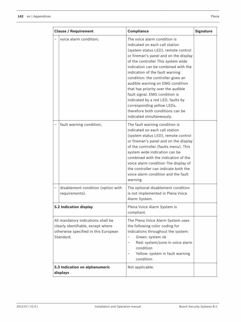
Clause / Requirement Compliance Signature
– voice alarm condition; The voice alarm condition isindicated on each call station(system status LED), remote controlor fireman’s panel and on the displayof the controller This system wideindication can be combined with theindication of the fault warningcondition: the controller gives anaudible warning on EMG conditionthat has priority over the audiblefault signal. EMG condition isindicated by a red LED, faults bycorresponding yellow LEDs,therefore both conditions can beindicated simultaneously.
– fault warning condition; The fault warning condition isindicated on each call station(system status LED), remote controlor fireman’s panel and on the displayof the controller (faults menu). Thissystem wide indication can becombined with the indication of thevoice alarm condition The display ofthe controller can indicate both thevoice alarm condition and the faultwarning.
– disablement condition (option withrequirements).
The optional disablement conditionis not implemented in Plena VoiceAlarm System.
5.2 Indication display Plena Voice Alarm System iscompliant.
All mandatory indications shall beclearly identifiable, except whereotherwise specified in this EuropeanStandard.
The Plena Voice Alarm System usesthe following color coding forindications throughout the system:– Green: system ok– Red: system/zone in voice alarm
condition– Yellow: system in fault warning
condition
5.3 Indication on alphanumericdisplays
Not applicable.
142 en | Appendices Plena
2013.07 | V2.0 | Installation and Operation manual Bosch Security Systems B.V.
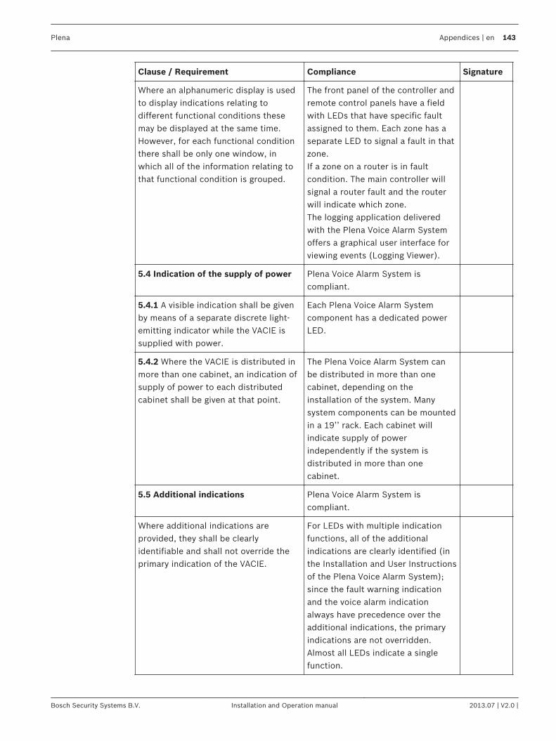
Clause / Requirement Compliance Signature
Where an alphanumeric display is usedto display indications relating todifferent functional conditions thesemay be displayed at the same time.However, for each functional conditionthere shall be only one window, inwhich all of the information relating tothat functional condition is grouped.
The front panel of the controller andremote control panels have a fieldwith LEDs that have specific faultassigned to them. Each zone has aseparate LED to signal a fault in thatzone.If a zone on a router is in faultcondition. The main controller willsignal a router fault and the routerwill indicate which zone.The logging application deliveredwith the Plena Voice Alarm Systemoffers a graphical user interface forviewing events (Logging Viewer).
5.4 Indication of the supply of power Plena Voice Alarm System iscompliant.
5.4.1 A visible indication shall be givenby means of a separate discrete light-emitting indicator while the VACIE issupplied with power.
Each Plena Voice Alarm Systemcomponent has a dedicated powerLED.
5.4.2 Where the VACIE is distributed inmore than one cabinet, an indication ofsupply of power to each distributedcabinet shall be given at that point.
The Plena Voice Alarm System canbe distributed in more than onecabinet, depending on theinstallation of the system. Manysystem components can be mountedin a 19’’ rack. Each cabinet willindicate supply of powerindependently if the system isdistributed in more than onecabinet.
5.5 Additional indications Plena Voice Alarm System iscompliant.
Where additional indications areprovided, they shall be clearlyidentifiable and shall not override theprimary indication of the VACIE.
For LEDs with multiple indicationfunctions, all of the additionalindications are clearly identified (inthe Installation and User Instructionsof the Plena Voice Alarm System);since the fault warning indicationand the voice alarm indicationalways have precedence over theadditional indications, the primaryindications are not overridden.Almost all LEDs indicate a singlefunction.
Plena Appendices | en 143
Bosch Security Systems B.V. Installation and Operation manual 2013.07 | V2.0 |
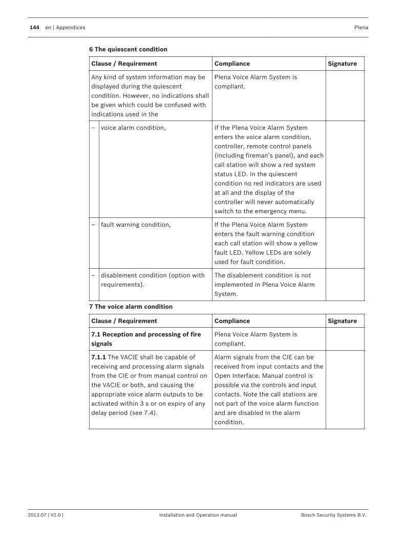
6 The quiescent condition
Clause / Requirement Compliance Signature
Any kind of system information may bedisplayed during the quiescentcondition. However, no indications shallbe given which could be confused withindications used in the
Plena Voice Alarm System iscompliant.
– voice alarm condition, If the Plena Voice Alarm Systementers the voice alarm condition,controller, remote control panels(including fireman’s panel), and eachcall station will show a red systemstatus LED. In the quiescentcondition no red indicators are usedat all and the display of thecontroller will never automaticallyswitch to the emergency menu.
– fault warning condition, If the Plena Voice Alarm Systementers the fault warning conditioneach call station will show a yellowfault LED. Yellow LEDs are solelyused for fault condition.
– disablement condition (option withrequirements).
The disablement condition is notimplemented in Plena Voice AlarmSystem.
7 The voice alarm condition
Clause / Requirement Compliance Signature
7.1 Reception and processing of firesignals
Plena Voice Alarm System iscompliant.
7.1.1 The VACIE shall be capable ofreceiving and processing alarm signalsfrom the CIE or from manual control onthe VACIE or both, and causing theappropriate voice alarm outputs to beactivated within 3 s or on expiry of anydelay period (see 7.4).
Alarm signals from the CIE can bereceived from input contacts and theOpen Interface. Manual control ispossible via the controls and inputcontacts. Note the call stations arenot part of the voice alarm functionand are disabled in the alarmcondition.
144 en | Appendices Plena
2013.07 | V2.0 | Installation and Operation manual Bosch Security Systems B.V.
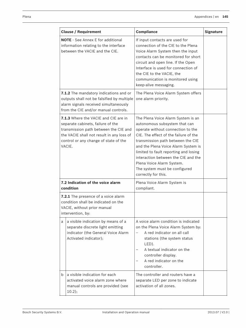
Clause / Requirement Compliance Signature
NOTE - See Annex E for additionalinformation relating to the interfacebetween the VACIE and the CIE.
If input contacts are used forconnection of the CIE to the PlenaVoice Alarm System then the inputcontacts can be monitored for shortcircuit and open line. If the OpenInterface is used for connection ofthe CIE to the VACIE, thecommunication is monitored usingkeep-alive messaging.
7.1.2 The mandatory indications and oroutputs shall not be falsified by multiplealarm signals received simultaneouslyfrom the CIE and/or manual controls.
The Plena Voice Alarm System offersone alarm priority.
7.1.3 Where the VACIE and CIE are inseparate cabinets, failure of thetransmission path between the CIE andthe VACIE shall not result in any loss ofcontrol or any change of state of theVACIE.
The Plena Voice Alarm System is anautonomous subsystem that canoperate without connection to theCIE. The effect of the failure of thetransmission path between the CIEand the Plena Voice Alarm System islimited to fault reporting and losinginteraction between the CIE and thePlena Voice Alarm System.The system must be configuredcorrectly for this.
7.2 Indication of the voice alarmcondition
Plena Voice Alarm System iscompliant.
7.2.1 The presence of a voice alarmcondition shall be indicated on theVACIE, without prior manualintervention, by:
a a visible indication by means of aseparate discrete light emittingindicator (the General Voice AlarmActivated indicator);
A voice alarm condition is indicatedon the Plena Voice Alarm System by:– A red indicator on all call
stations (the system statusLED).
– A textual indicator on thecontroller display.
– A red indicator on thecontroller.
b a visible indication for eachactivated voice alarm zone wheremanual controls are provided (see10.2);
The controller and routers have aseparate LED per zone to indicateactivation of all zones.
Plena Appendices | en 145
Bosch Security Systems B.V. Installation and Operation manual 2013.07 | V2.0 |
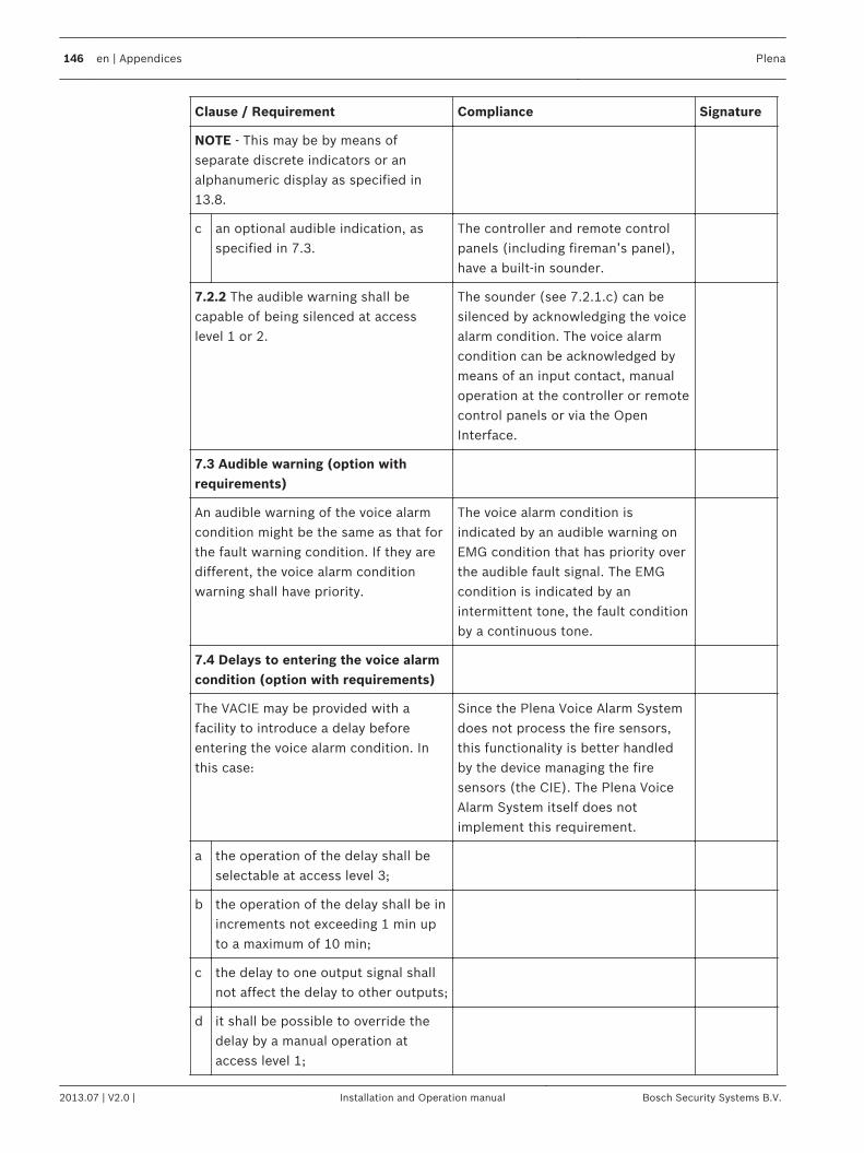
Clause / Requirement Compliance Signature
NOTE - This may be by means ofseparate discrete indicators or analphanumeric display as specified in13.8.
c an optional audible indication, asspecified in 7.3.
The controller and remote controlpanels (including fireman’s panel),have a built-in sounder.
7.2.2 The audible warning shall becapable of being silenced at accesslevel 1 or 2.
The sounder (see 7.2.1.c) can besilenced by acknowledging the voicealarm condition. The voice alarmcondition can be acknowledged bymeans of an input contact, manualoperation at the controller or remotecontrol panels or via the OpenInterface.
7.3 Audible warning (option withrequirements)
An audible warning of the voice alarmcondition might be the same as that forthe fault warning condition. If they aredifferent, the voice alarm conditionwarning shall have priority.
The voice alarm condition isindicated by an audible warning onEMG condition that has priority overthe audible fault signal. The EMGcondition is indicated by anintermittent tone, the fault conditionby a continuous tone.
7.4 Delays to entering the voice alarmcondition (option with requirements)
The VACIE may be provided with afacility to introduce a delay beforeentering the voice alarm condition. Inthis case:
Since the Plena Voice Alarm Systemdoes not process the fire sensors,this functionality is better handledby the device managing the firesensors (the CIE). The Plena VoiceAlarm System itself does notimplement this requirement.
a the operation of the delay shall beselectable at access level 3;
b the operation of the delay shall be inincrements not exceeding 1 min upto a maximum of 10 min;
c the delay to one output signal shallnot affect the delay to other outputs;
d it shall be possible to override thedelay by a manual operation ataccess level 1;
146 en | Appendices Plena
2013.07 | V2.0 | Installation and Operation manual Bosch Security Systems B.V.
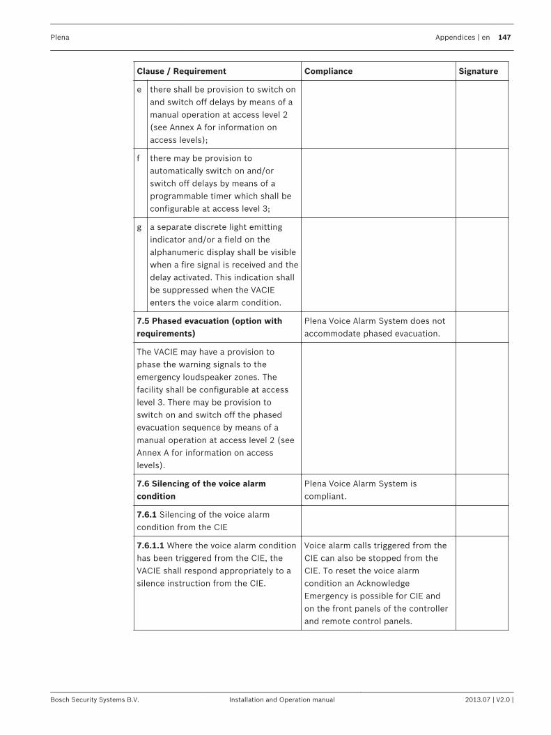
Clause / Requirement Compliance Signature
e there shall be provision to switch onand switch off delays by means of amanual operation at access level 2(see Annex A for information onaccess levels);
f there may be provision toautomatically switch on and/orswitch off delays by means of aprogrammable timer which shall beconfigurable at access level 3;
g a separate discrete light emittingindicator and/or a field on thealphanumeric display shall be visiblewhen a fire signal is received and thedelay activated. This indication shallbe suppressed when the VACIEenters the voice alarm condition.
7.5 Phased evacuation (option withrequirements)
Plena Voice Alarm System does notaccommodate phased evacuation.
The VACIE may have a provision tophase the warning signals to theemergency loudspeaker zones. Thefacility shall be configurable at accesslevel 3. There may be provision toswitch on and switch off the phasedevacuation sequence by means of amanual operation at access level 2 (seeAnnex A for information on accesslevels).
7.6 Silencing of the voice alarmcondition
Plena Voice Alarm System iscompliant.
7.6.1 Silencing of the voice alarmcondition from the CIE
7.6.1.1 Where the voice alarm conditionhas been triggered from the CIE, theVACIE shall respond appropriately to asilence instruction from the CIE.
Voice alarm calls triggered from theCIE can also be stopped from theCIE. To reset the voice alarmcondition an AcknowledgeEmergency is possible for CIE andon the front panels of the controllerand remote control panels.
Plena Appendices | en 147
Bosch Security Systems B.V. Installation and Operation manual 2013.07 | V2.0 |
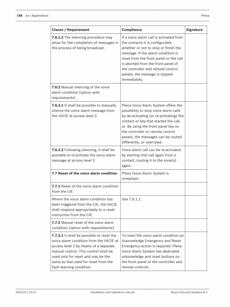
Clause / Requirement Compliance Signature
7.6.1.2 The silencing procedure mayallow for the completion of messages inthe process of being broadcast.
If a voice alarm call is activated fromthe contacts it is configurablewhether or not to stop or finish themessage. If the alarm condition isreset from the front panel or the callis aborted from the front panel ofthe controller and remote controlpanels, the message is toppedimmediately.
7.6.2 Manual silencing of the voicealarm condition (option withrequirements)
7.6.2.1 It shall be possible to manuallysilence the voice alarm message fromthe VACIE at access level 2.
Plena Voice Alarm System offers thepossibility to stop voice alarm callsby de-activating (or re-activating) thecontact or key that started the call,or. By using the front panel key onthe controller or remote controlpanels, the messages can be routeddifferently, or overruled.
7.6.2.2 Following silencing, it shall bepossible to re-activate the voice alarmmessage at access level 2.
Voice alarm call can be re-activatedby starting that call again from acontact, routing it to the zone(s)again.
7.7 Reset of the voice alarm condition Plena Voice Alarm System iscompliant.
7.7.1 Reset of the voice alarm conditionfrom the CIE
Where the voice alarm condition hasbeen triggered from the CIE, the VACIEshall respond appropriately to a resetinstruction from the CIE.
See 7.6.1.1.
7.7.2 Manual reset of the voice alarmcondition (option with requirements)
7.7.2.1 It shall be possible to reset thevoice alarm condition from the VACIE ataccess level 2 by means of a separatemanual control. This control shall beused only for reset and may be thesame as that used for reset from thefault warning condition.
To reset the voice alarm condition anAcknowledge Emergency and ResetEmergency action is required. PlenaVoice Alarm System has dedicatedacknowledge and reset buttons onthe front panel of the controller andremote controls.
148 en | Appendices Plena
2013.07 | V2.0 | Installation and Operation manual Bosch Security Systems B.V.
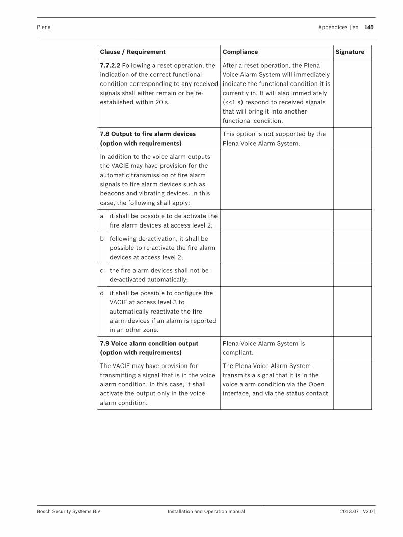
Clause / Requirement Compliance Signature
7.7.2.2 Following a reset operation, theindication of the correct functionalcondition corresponding to any receivedsignals shall either remain or be re-established within 20 s.
After a reset operation, the PlenaVoice Alarm System will immediatelyindicate the functional condition it iscurrently in. It will also immediately(<<1 s) respond to received signalsthat will bring it into anotherfunctional condition.
7.8 Output to fire alarm devices(option with requirements)
This option is not supported by thePlena Voice Alarm System.
In addition to the voice alarm outputsthe VACIE may have provision for theautomatic transmission of fire alarmsignals to fire alarm devices such asbeacons and vibrating devices. In thiscase, the following shall apply:
a it shall be possible to de-activate thefire alarm devices at access level 2;
b following de-activation, it shall bepossible to re-activate the fire alarmdevices at access level 2;
c the fire alarm devices shall not bede-activated automatically;
d it shall be possible to configure theVACIE at access level 3 toautomatically reactivate the firealarm devices if an alarm is reportedin an other zone.
7.9 Voice alarm condition output(option with requirements)
Plena Voice Alarm System iscompliant.
The VACIE may have provision fortransmitting a signal that is in the voicealarm condition. In this case, it shallactivate the output only in the voicealarm condition.
The Plena Voice Alarm Systemtransmits a signal that it is in thevoice alarm condition via the OpenInterface, and via the status contact.
Plena Appendices | en 149
Bosch Security Systems B.V. Installation and Operation manual 2013.07 | V2.0 |
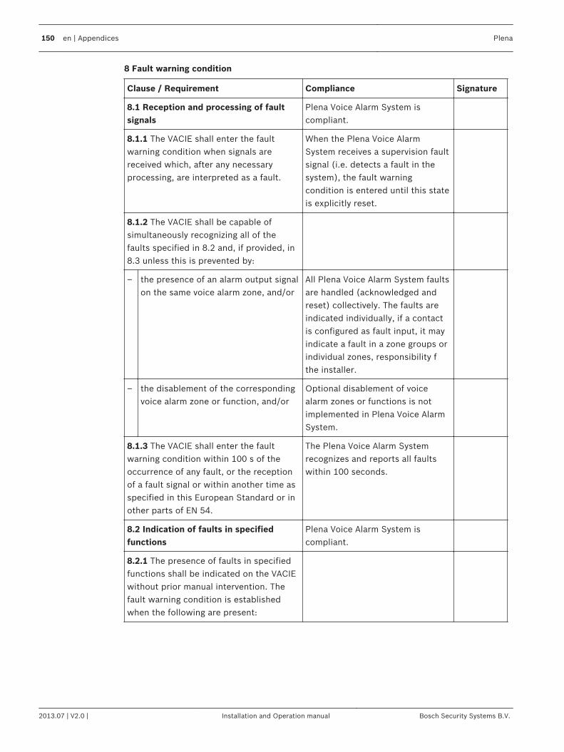
8 Fault warning condition
Clause / Requirement Compliance Signature
8.1 Reception and processing of faultsignals
Plena Voice Alarm System iscompliant.
8.1.1 The VACIE shall enter the faultwarning condition when signals arereceived which, after any necessaryprocessing, are interpreted as a fault.
When the Plena Voice AlarmSystem receives a supervision faultsignal (i.e. detects a fault in thesystem), the fault warningcondition is entered until this stateis explicitly reset.
8.1.2 The VACIE shall be capable ofsimultaneously recognizing all of thefaults specified in 8.2 and, if provided, in8.3 unless this is prevented by:
– the presence of an alarm output signalon the same voice alarm zone, and/or
All Plena Voice Alarm System faultsare handled (acknowledged andreset) collectively. The faults areindicated individually, if a contactis configured as fault input, it mayindicate a fault in a zone groups orindividual zones, responsibility fthe installer.
– the disablement of the correspondingvoice alarm zone or function, and/or
Optional disablement of voicealarm zones or functions is notimplemented in Plena Voice AlarmSystem.
8.1.3 The VACIE shall enter the faultwarning condition within 100 s of theoccurrence of any fault, or the receptionof a fault signal or within another time asspecified in this European Standard or inother parts of EN 54.
The Plena Voice Alarm Systemrecognizes and reports all faultswithin 100 seconds.
8.2 Indication of faults in specifiedfunctions
Plena Voice Alarm System iscompliant.
8.2.1 The presence of faults in specifiedfunctions shall be indicated on the VACIEwithout prior manual intervention. Thefault warning condition is establishedwhen the following are present:
150 en | Appendices Plena
2013.07 | V2.0 | Installation and Operation manual Bosch Security Systems B.V.
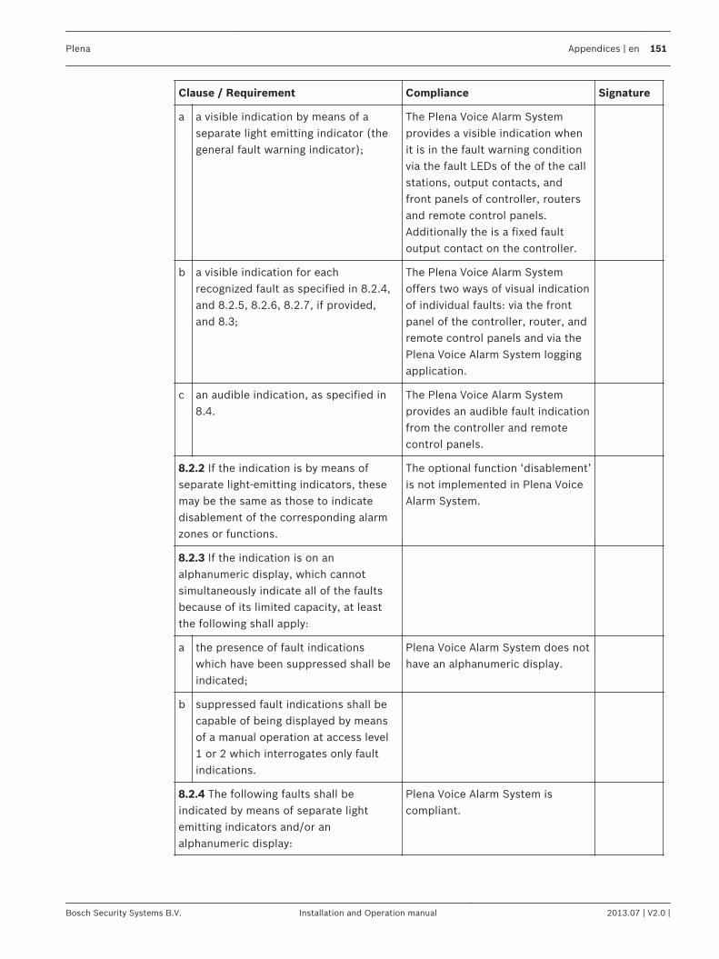
Clause / Requirement Compliance Signature
a a visible indication by means of aseparate light emitting indicator (thegeneral fault warning indicator);
The Plena Voice Alarm Systemprovides a visible indication whenit is in the fault warning conditionvia the fault LEDs of the of the callstations, output contacts, andfront panels of controller, routersand remote control panels.Additionally the is a fixed faultoutput contact on the controller.
b a visible indication for eachrecognized fault as specified in 8.2.4,and 8.2.5, 8.2.6, 8.2.7, if provided,and 8.3;
The Plena Voice Alarm Systemoffers two ways of visual indicationof individual faults: via the frontpanel of the controller, router, andremote control panels and via thePlena Voice Alarm System loggingapplication.
c an audible indication, as specified in8.4.
The Plena Voice Alarm Systemprovides an audible fault indicationfrom the controller and remotecontrol panels.
8.2.2 If the indication is by means ofseparate light-emitting indicators, thesemay be the same as those to indicatedisablement of the corresponding alarmzones or functions.
The optional function ‘disablement’is not implemented in Plena VoiceAlarm System.
8.2.3 If the indication is on analphanumeric display, which cannotsimultaneously indicate all of the faultsbecause of its limited capacity, at leastthe following shall apply:
a the presence of fault indicationswhich have been suppressed shall beindicated;
Plena Voice Alarm System does nothave an alphanumeric display.
b suppressed fault indications shall becapable of being displayed by meansof a manual operation at access level1 or 2 which interrogates only faultindications.
8.2.4 The following faults shall beindicated by means of separate lightemitting indicators and/or analphanumeric display:
Plena Voice Alarm System iscompliant.
Plena Appendices | en 151
Bosch Security Systems B.V. Installation and Operation manual 2013.07 | V2.0 |
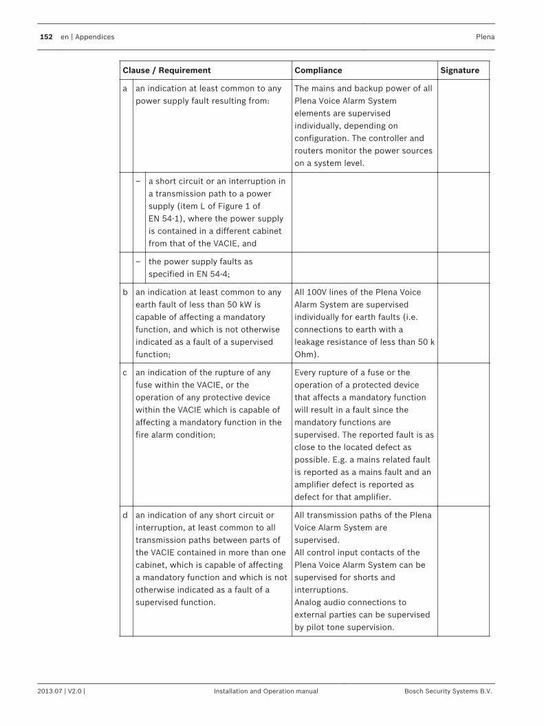
Clause / Requirement Compliance Signature
a an indication at least common to anypower supply fault resulting from:
The mains and backup power of allPlena Voice Alarm Systemelements are supervisedindividually, depending onconfiguration. The controller androuters monitor the power sourceson a system level.
– a short circuit or an interruption ina transmission path to a powersupply (item L of Figure 1 ofEN 54-1), where the power supplyis contained in a different cabinetfrom that of the VACIE, and
– the power supply faults asspecified in EN 54-4;
b an indication at least common to anyearth fault of less than 50 kW iscapable of affecting a mandatoryfunction, and which is not otherwiseindicated as a fault of a supervisedfunction;
All 100V lines of the Plena VoiceAlarm System are supervisedindividually for earth faults (i.e.connections to earth with aleakage resistance of less than 50 kOhm).
c an indication of the rupture of anyfuse within the VACIE, or theoperation of any protective devicewithin the VACIE which is capable ofaffecting a mandatory function in thefire alarm condition;
Every rupture of a fuse or theoperation of a protected devicethat affects a mandatory functionwill result in a fault since themandatory functions aresupervised. The reported fault is asclose to the located defect aspossible. E.g. a mains related faultis reported as a mains fault and anamplifier defect is reported asdefect for that amplifier.
d an indication of any short circuit orinterruption, at least common to alltransmission paths between parts ofthe VACIE contained in more than onecabinet, which is capable of affectinga mandatory function and which is nototherwise indicated as a fault of asupervised function.
All transmission paths of the PlenaVoice Alarm System aresupervised.All control input contacts of thePlena Voice Alarm System can besupervised for shorts andinterruptions.Analog audio connections toexternal parties can be supervisedby pilot tone supervision.
152 en | Appendices Plena
2013.07 | V2.0 | Installation and Operation manual Bosch Security Systems B.V.
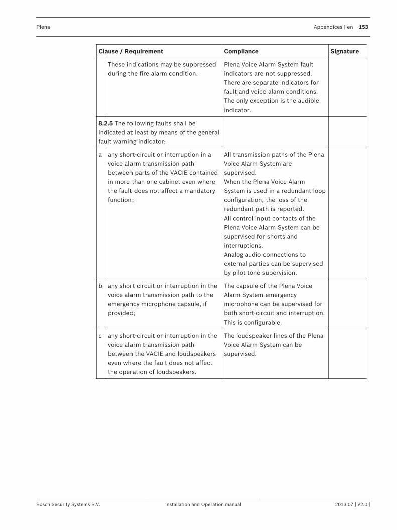
Clause / Requirement Compliance Signature
These indications may be suppressedduring the fire alarm condition.
Plena Voice Alarm System faultindicators are not suppressed.There are separate indicators forfault and voice alarm conditions.The only exception is the audibleindicator.
8.2.5 The following faults shall beindicated at least by means of the generalfault warning indicator:
a any short-circuit or interruption in avoice alarm transmission pathbetween parts of the VACIE containedin more than one cabinet even wherethe fault does not affect a mandatoryfunction;
All transmission paths of the PlenaVoice Alarm System aresupervised.When the Plena Voice AlarmSystem is used in a redundant loopconfiguration, the loss of theredundant path is reported.All control input contacts of thePlena Voice Alarm System can besupervised for shorts andinterruptions.Analog audio connections toexternal parties can be supervisedby pilot tone supervision.
b any short-circuit or interruption in thevoice alarm transmission path to theemergency microphone capsule, ifprovided;
The capsule of the Plena VoiceAlarm System emergencymicrophone can be supervised forboth short-circuit and interruption.This is configurable.
c any short-circuit or interruption in thevoice alarm transmission pathbetween the VACIE and loudspeakerseven where the fault does not affectthe operation of loudspeakers.
The loudspeaker lines of the PlenaVoice Alarm System can besupervised.
Plena Appendices | en 153
Bosch Security Systems B.V. Installation and Operation manual 2013.07 | V2.0 |
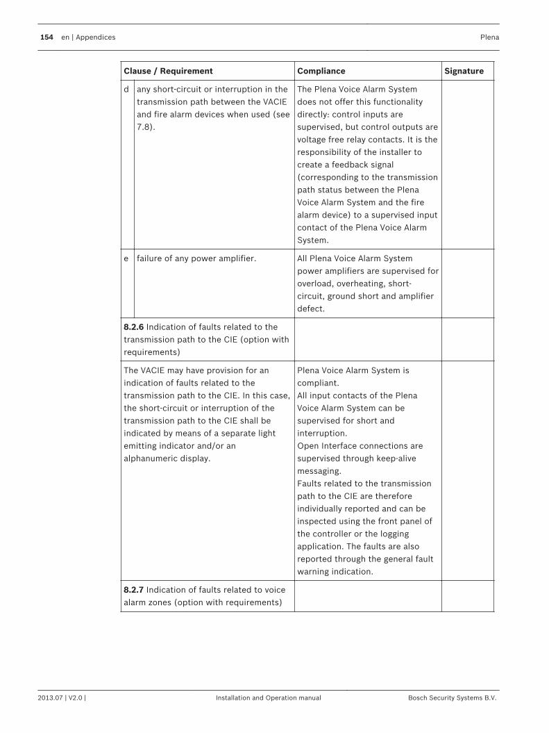
Clause / Requirement Compliance Signature
d any short-circuit or interruption in thetransmission path between the VACIEand fire alarm devices when used (see7.8).
The Plena Voice Alarm Systemdoes not offer this functionalitydirectly: control inputs aresupervised, but control outputs arevoltage free relay contacts. It is theresponsibility of the installer tocreate a feedback signal(corresponding to the transmissionpath status between the PlenaVoice Alarm System and the firealarm device) to a supervised inputcontact of the Plena Voice AlarmSystem.
e failure of any power amplifier. All Plena Voice Alarm Systempower amplifiers are supervised foroverload, overheating, short-circuit, ground short and amplifierdefect.
8.2.6 Indication of faults related to thetransmission path to the CIE (option withrequirements)
The VACIE may have provision for anindication of faults related to thetransmission path to the CIE. In this case,the short-circuit or interruption of thetransmission path to the CIE shall beindicated by means of a separate lightemitting indicator and/or analphanumeric display.
Plena Voice Alarm System iscompliant.All input contacts of the PlenaVoice Alarm System can besupervised for short andinterruption.Open Interface connections aresupervised through keep-alivemessaging.Faults related to the transmissionpath to the CIE are thereforeindividually reported and can beinspected using the front panel ofthe controller or the loggingapplication. The faults are alsoreported through the general faultwarning indication.
8.2.7 Indication of faults related to voicealarm zones (option with requirements)
154 en | Appendices Plena
2013.07 | V2.0 | Installation and Operation manual Bosch Security Systems B.V.
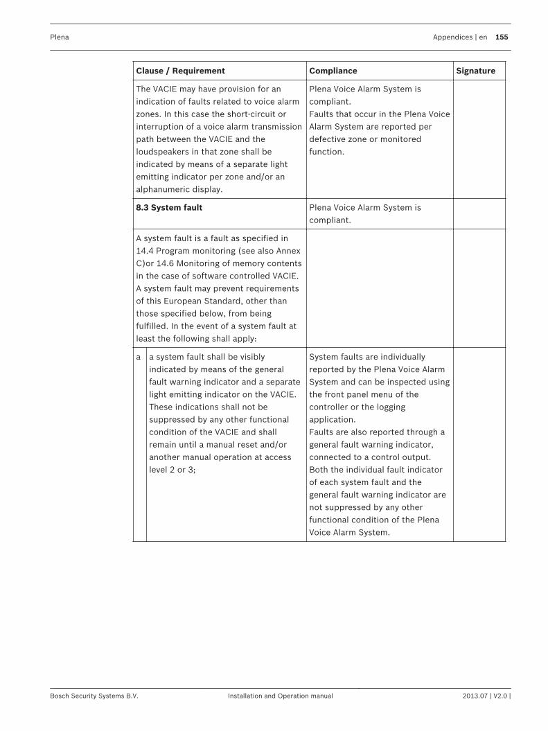
Clause / Requirement Compliance Signature
The VACIE may have provision for anindication of faults related to voice alarmzones. In this case the short-circuit orinterruption of a voice alarm transmissionpath between the VACIE and theloudspeakers in that zone shall beindicated by means of a separate lightemitting indicator per zone and/or analphanumeric display.
Plena Voice Alarm System iscompliant.Faults that occur in the Plena VoiceAlarm System are reported perdefective zone or monitoredfunction.
8.3 System fault Plena Voice Alarm System iscompliant.
A system fault is a fault as specified in14.4 Program monitoring (see also AnnexC)or 14.6 Monitoring of memory contentsin the case of software controlled VACIE.A system fault may prevent requirementsof this European Standard, other thanthose specified below, from beingfulfilled. In the event of a system fault atleast the following shall apply:
a a system fault shall be visiblyindicated by means of the generalfault warning indicator and a separatelight emitting indicator on the VACIE.These indications shall not besuppressed by any other functionalcondition of the VACIE and shallremain until a manual reset and/oranother manual operation at accesslevel 2 or 3;
System faults are individuallyreported by the Plena Voice AlarmSystem and can be inspected usingthe front panel menu of thecontroller or the loggingapplication.Faults are also reported through ageneral fault warning indicator,connected to a control output.Both the individual fault indicatorof each system fault and thegeneral fault warning indicator arenot suppressed by any otherfunctional condition of the PlenaVoice Alarm System.
Plena Appendices | en 155
Bosch Security Systems B.V. Installation and Operation manual 2013.07 | V2.0 |
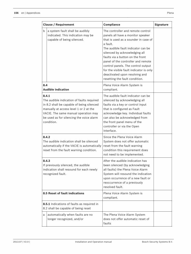
Clause / Requirement Compliance Signature
b a system fault shall be audiblyindicated. This indication may becapable of being silenced.
The controller and remote controlpanels all have a monitor speakerthat is used as a sounder in case ofa fault.The audible fault indicator can besilenced by acknowledging allfaults via a button on the frontpanel of the controller and remotecontrol panels. The control outputfor the visible fault indicator is onlydeactivated upon resolving andresetting the fault condition.
8.4Audible indication
Plena Voice Alarm System iscompliant.
8.4.1The audible indication of faults requiredin 8.2 shall be capable of being silencedmanually at access level 1 or 2 at theVACIE. The same manual operation maybe used as for silencing the voice alarmcondition.
The audible fault indicator can besilenced by acknowledging allfaults via a key or control inputthat is configured as Faultacknowledge key. Individual faultscan also be acknowledged fromthe front panel menu of thecontroller or via the OpenInterface.
8.4.2The audible indication shall be silencedautomatically if the VACIE is automaticallyreset from the fault warning condition.
Since the Plena Voice AlarmSystem does not offer automaticreset from the fault warningcondition this requirement doesnot need to be implemented.
8.4.3If previously silenced, the audibleindication shall resound for each newlyrecognized fault.
After the audible indication hasbeen silenced (by acknowledgingall faults) the Plena Voice AlarmSystem will resound the indicationupon occurrence of a new fault orreoccurrence of a previouslyresolved fault.
8.5 Reset of fault indications Plena Voice Alarm System iscompliant.
8.5.1 Indications of faults as required in8.2 shall be capable of being reset
a automatically when faults are nolonger recognized, and/or
The Plena Voice Alarm Systemdoes not offer automatic reset offaults
156 en | Appendices Plena
2013.07 | V2.0 | Installation and Operation manual Bosch Security Systems B.V.
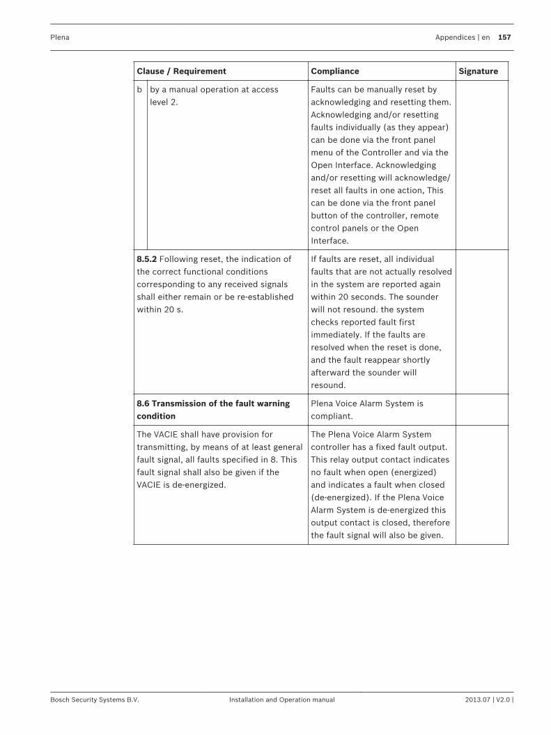
Clause / Requirement Compliance Signature
b by a manual operation at accesslevel 2.
Faults can be manually reset byacknowledging and resetting them.Acknowledging and/or resettingfaults individually (as they appear)can be done via the front panelmenu of the Controller and via theOpen Interface. Acknowledgingand/or resetting will acknowledge/reset all faults in one action, Thiscan be done via the front panelbutton of the controller, remotecontrol panels or the OpenInterface.
8.5.2 Following reset, the indication ofthe correct functional conditionscorresponding to any received signalsshall either remain or be re-establishedwithin 20 s.
If faults are reset, all individualfaults that are not actually resolvedin the system are reported againwithin 20 seconds. The sounderwill not resound. the systemchecks reported fault firstimmediately. If the faults areresolved when the reset is done,and the fault reappear shortlyafterward the sounder willresound.
8.6 Transmission of the fault warningcondition
Plena Voice Alarm System iscompliant.
The VACIE shall have provision fortransmitting, by means of at least generalfault signal, all faults specified in 8. Thisfault signal shall also be given if theVACIE is de-energized.
The Plena Voice Alarm Systemcontroller has a fixed fault output.This relay output contact indicatesno fault when open (energized)and indicates a fault when closed(de-energized). If the Plena VoiceAlarm System is de-energized thisoutput contact is closed, thereforethe fault signal will also be given.
Plena Appendices | en 157
Bosch Security Systems B.V. Installation and Operation manual 2013.07 | V2.0 |
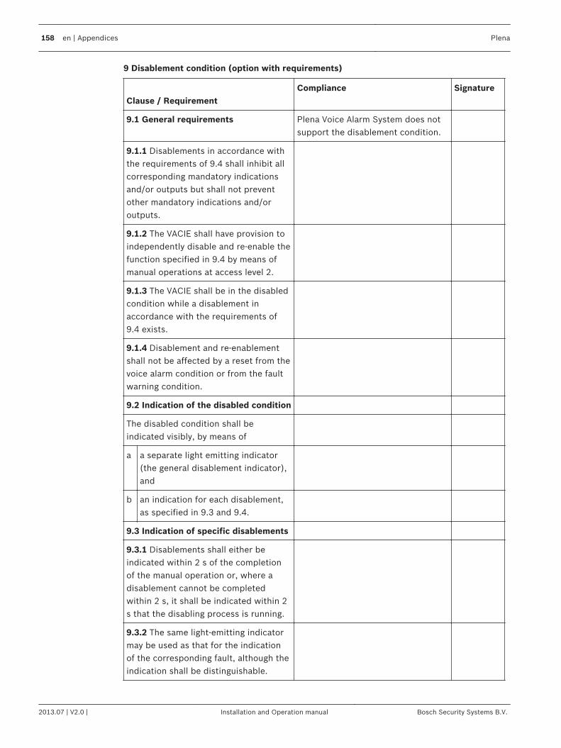
9 Disablement condition (option with requirements)
Clause / Requirement
Compliance Signature
9.1 General requirements Plena Voice Alarm System does notsupport the disablement condition.
9.1.1 Disablements in accordance withthe requirements of 9.4 shall inhibit allcorresponding mandatory indicationsand/or outputs but shall not preventother mandatory indications and/oroutputs.
9.1.2 The VACIE shall have provision toindependently disable and re-enable thefunction specified in 9.4 by means ofmanual operations at access level 2.
9.1.3 The VACIE shall be in the disabledcondition while a disablement inaccordance with the requirements of9.4 exists.
9.1.4 Disablement and re-enablementshall not be affected by a reset from thevoice alarm condition or from the faultwarning condition.
9.2 Indication of the disabled condition
The disabled condition shall beindicated visibly, by means of
a a separate light emitting indicator(the general disablement indicator),and
b an indication for each disablement,as specified in 9.3 and 9.4.
9.3 Indication of specific disablements
9.3.1 Disablements shall either beindicated within 2 s of the completionof the manual operation or, where adisablement cannot be completedwithin 2 s, it shall be indicated within 2s that the disabling process is running.
9.3.2 The same light-emitting indicatormay be used as that for the indicationof the corresponding fault, although theindication shall be distinguishable.
158 en | Appendices Plena
2013.07 | V2.0 | Installation and Operation manual Bosch Security Systems B.V.
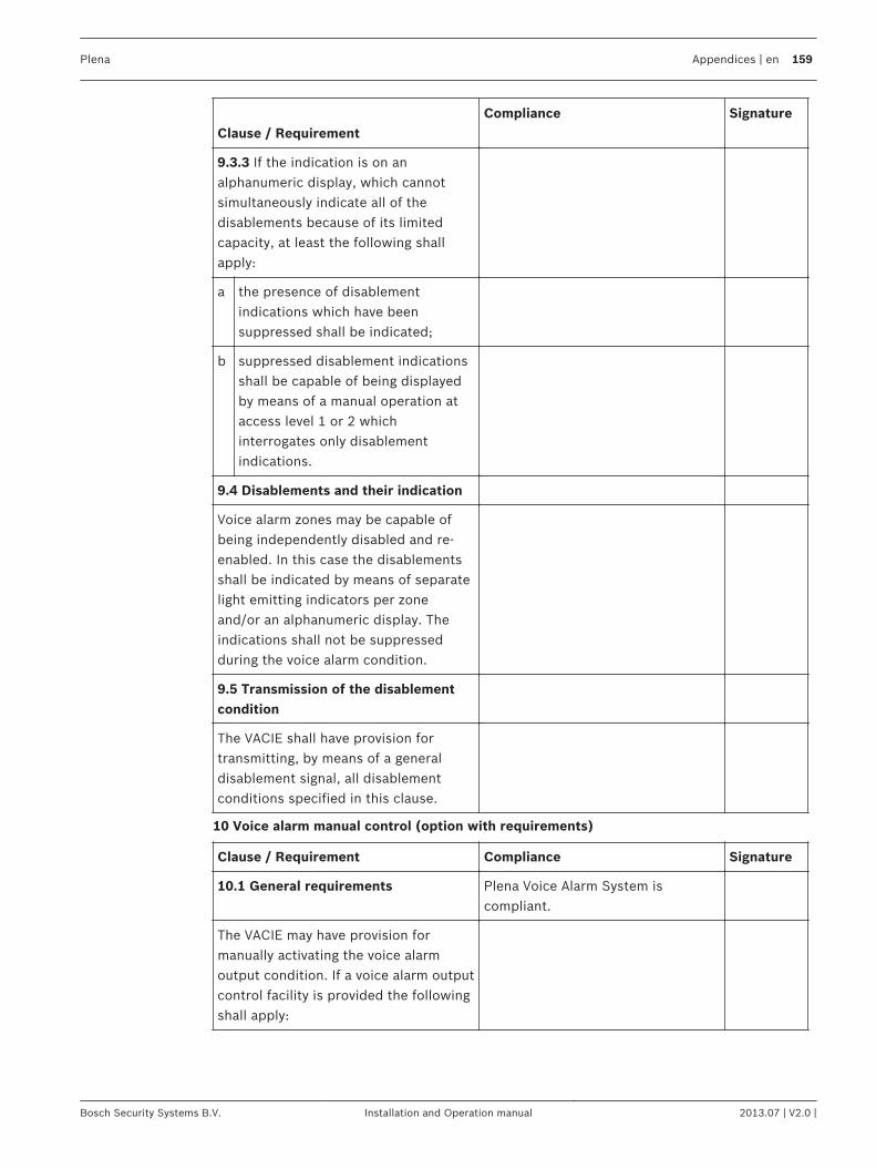
Clause / Requirement
Compliance Signature
9.3.3 If the indication is on analphanumeric display, which cannotsimultaneously indicate all of thedisablements because of its limitedcapacity, at least the following shallapply:
a the presence of disablementindications which have beensuppressed shall be indicated;
b suppressed disablement indicationsshall be capable of being displayedby means of a manual operation ataccess level 1 or 2 whichinterrogates only disablementindications.
9.4 Disablements and their indication
Voice alarm zones may be capable ofbeing independently disabled and re-enabled. In this case the disablementsshall be indicated by means of separatelight emitting indicators per zoneand/or an alphanumeric display. Theindications shall not be suppressedduring the voice alarm condition.
9.5 Transmission of the disablementcondition
The VACIE shall have provision fortransmitting, by means of a generaldisablement signal, all disablementconditions specified in this clause.
10 Voice alarm manual control (option with requirements)
Clause / Requirement Compliance Signature
10.1 General requirements Plena Voice Alarm System iscompliant.
The VACIE may have provision formanually activating the voice alarmoutput condition. If a voice alarm outputcontrol facility is provided the followingshall apply:
Plena Appendices | en 159
Bosch Security Systems B.V. Installation and Operation manual 2013.07 | V2.0 |
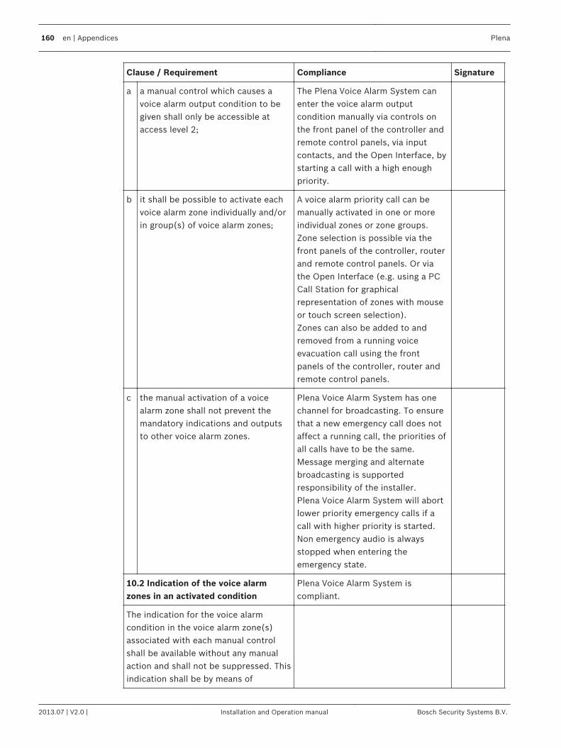
Clause / Requirement Compliance Signature
a a manual control which causes avoice alarm output condition to begiven shall only be accessible ataccess level 2;
The Plena Voice Alarm System canenter the voice alarm outputcondition manually via controls onthe front panel of the controller andremote control panels, via inputcontacts, and the Open Interface, bystarting a call with a high enoughpriority.
b it shall be possible to activate eachvoice alarm zone individually and/orin group(s) of voice alarm zones;
A voice alarm priority call can bemanually activated in one or moreindividual zones or zone groups.Zone selection is possible via thefront panels of the controller, routerand remote control panels. Or viathe Open Interface (e.g. using a PCCall Station for graphicalrepresentation of zones with mouseor touch screen selection).Zones can also be added to andremoved from a running voiceevacuation call using the frontpanels of the controller, router andremote control panels.
c the manual activation of a voicealarm zone shall not prevent themandatory indications and outputsto other voice alarm zones.
Plena Voice Alarm System has onechannel for broadcasting. To ensurethat a new emergency call does notaffect a running call, the priorities ofall calls have to be the same.Message merging and alternatebroadcasting is supportedresponsibility of the installer.Plena Voice Alarm System will abortlower priority emergency calls if acall with higher priority is started.Non emergency audio is alwaysstopped when entering theemergency state.
10.2 Indication of the voice alarmzones in an activated condition
Plena Voice Alarm System iscompliant.
The indication for the voice alarmcondition in the voice alarm zone(s)associated with each manual controlshall be available without any manualaction and shall not be suppressed. Thisindication shall be by means of
160 en | Appendices Plena
2013.07 | V2.0 | Installation and Operation manual Bosch Security Systems B.V.
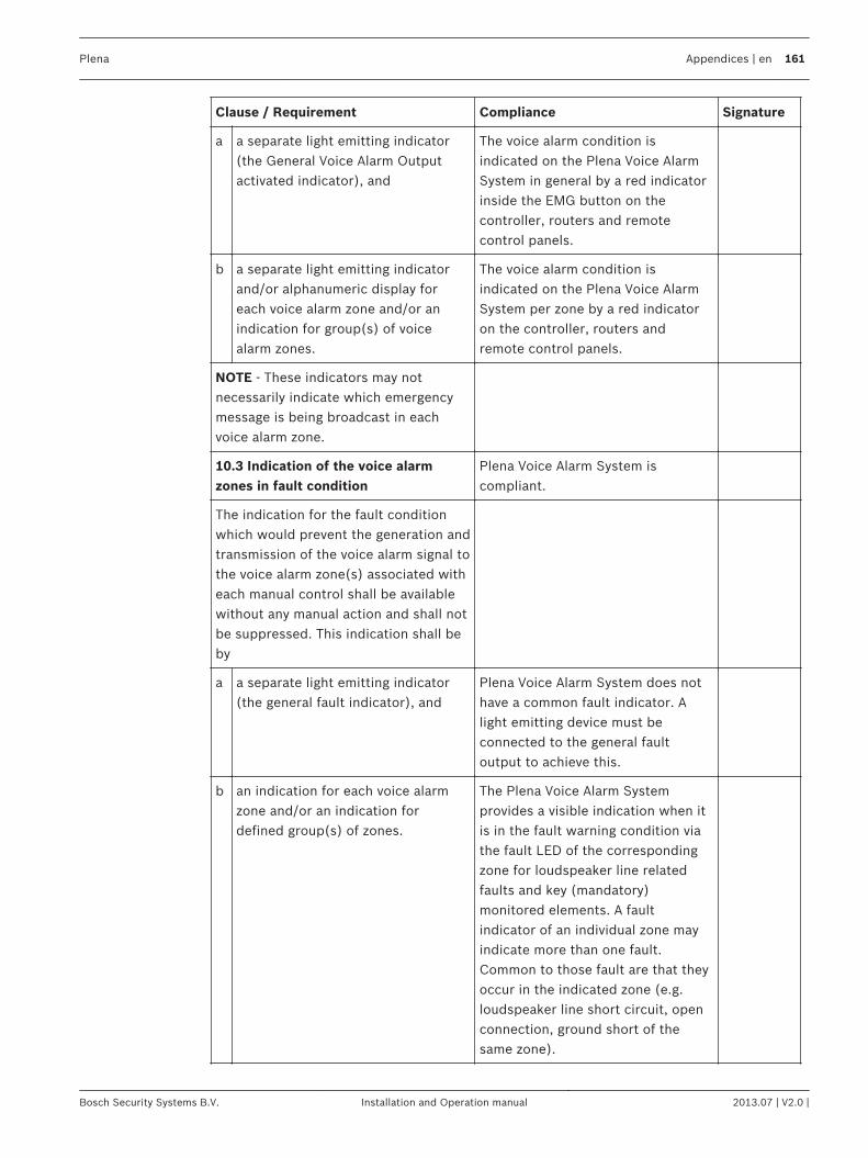
Clause / Requirement Compliance Signature
a a separate light emitting indicator(the General Voice Alarm Outputactivated indicator), and
The voice alarm condition isindicated on the Plena Voice AlarmSystem in general by a red indicatorinside the EMG button on thecontroller, routers and remotecontrol panels.
b a separate light emitting indicatorand/or alphanumeric display foreach voice alarm zone and/or anindication for group(s) of voicealarm zones.
The voice alarm condition isindicated on the Plena Voice AlarmSystem per zone by a red indicatoron the controller, routers andremote control panels.
NOTE - These indicators may notnecessarily indicate which emergencymessage is being broadcast in eachvoice alarm zone.
10.3 Indication of the voice alarmzones in fault condition
Plena Voice Alarm System iscompliant.
The indication for the fault conditionwhich would prevent the generation andtransmission of the voice alarm signal tothe voice alarm zone(s) associated witheach manual control shall be availablewithout any manual action and shall notbe suppressed. This indication shall beby
a a separate light emitting indicator(the general fault indicator), and
Plena Voice Alarm System does nothave a common fault indicator. Alight emitting device must beconnected to the general faultoutput to achieve this.
b an indication for each voice alarmzone and/or an indication fordefined group(s) of zones.
The Plena Voice Alarm Systemprovides a visible indication when itis in the fault warning condition viathe fault LED of the correspondingzone for loudspeaker line relatedfaults and key (mandatory)monitored elements. A faultindicator of an individual zone mayindicate more than one fault.Common to those fault are that theyoccur in the indicated zone (e.g.loudspeaker line short circuit, openconnection, ground short of thesame zone).
Plena Appendices | en 161
Bosch Security Systems B.V. Installation and Operation manual 2013.07 | V2.0 |
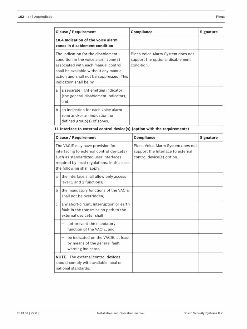
Clause / Requirement Compliance Signature
10.4 Indication of the voice alarmzones in disablement condition
The indication for the disablementcondition in the voice alarm zone(s)associated with each manual controlshall be available without any manualaction and shall not be suppressed. Thisindication shall be by
Plena Voice Alarm System does notsupport the optional disablementcondition.
a a separate light emitting indicator(the general disablement indicator),and
b an indication for each voice alarmzone and/or an indication fordefined group(s) of zones.
11 Interface to external control device(s) (option with the requirements)
Clause / Requirement Compliance Signature
The VACIE may have provision forinterfacing to external control device(s)such as standardized user interfacesrequired by local regulations. In this case,the following shall apply:
Plena Voice Alarm System does notsupport the Interface to externalcontrol device(s) option.
a the interface shall allow only accesslevel 1 and 2 functions;
b the mandatory functions of the VACIEshall not be overridden;
c any short-circuit, interruption or earthfault in the transmission path to theexternal device(s) shall
– not prevent the mandatoryfunction of the VACIE, and
– be indicated on the VACIE, at leastby means of the general faultwarning indicator.
NOTE - The external control devicesshould comply with available local ornational standards.
162 en | Appendices Plena
2013.07 | V2.0 | Installation and Operation manual Bosch Security Systems B.V.
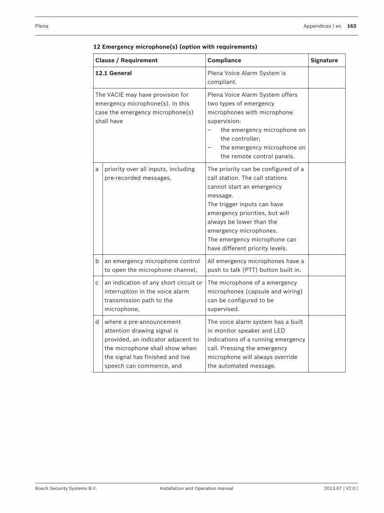
12 Emergency microphone(s) (option with requirements)
Clause / Requirement Compliance Signature
12.1 General Plena Voice Alarm System iscompliant.
The VACIE may have provision foremergency microphone(s). In thiscase the emergency microphone(s)shall have
Plena Voice Alarm System offerstwo types of emergencymicrophones with microphonesupervision:– the emergency microphone on
the controller;– the emergency microphone on
the remote control panels.
a priority over all inputs, includingpre-recorded messages,
The priority can be configured of acall station. The call stationscannot start an emergencymessage.The trigger inputs can haveemergency priorities, but willalways be lower than theemergency microphones.The emergency microphone canhave different priority levels.
b an emergency microphone controlto open the microphone channel,
All emergency microphones have apush to talk (PTT) button built in.
c an indication of any short circuit orinterruption in the voice alarmtransmission path to themicrophone,
The microphone of a emergencymicrophones (capsule and wiring)can be configured to besupervised.
d where a pre-announcementattention drawing signal isprovided, an indicator adjacent tothe microphone shall show whenthe signal has finished and livespeech can commence, and
The voice alarm system has a builtin monitor speaker and LEDindications of a running emergencycall. Pressing the emergencymicrophone will always overridethe automated message.
Plena Appendices | en 163
Bosch Security Systems B.V. Installation and Operation manual 2013.07 | V2.0 |
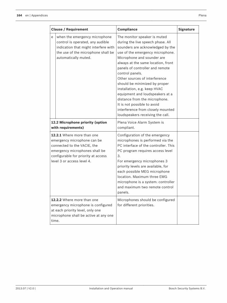
Clause / Requirement Compliance Signature
e when the emergency microphonecontrol is operated, any audibleindication that might interfere withthe use of the microphone shall beautomatically muted.
The monitor speaker is mutedduring the live speech phase. Allsounders are acknowledged by theuse of the emergency microphone.Microphone and sounder arealways at the same location, frontpanels of controller and remotecontrol panels.Other sources of interferenceshould be minimized by properinstallation, e.g. keep HVACequipment and loudspeakers at adistance from the microphone.It is not possible to avoidinterference from closely mountedloudspeakers receiving the call.
12.2 Microphone priority (optionwith requirements)
Plena Voice Alarm System iscompliant.
12.2.1 Where more than oneemergency microphone can beconnected to the VACIE, theemergency microphones shall beconfigurable for priority at accesslevel 3 or access level 4.
Configuration of the emergencymicrophones is performed via thePC interface of the controller. ThisPC program requires access level3.For emergency microphones 3priority levels are available, foreach possible MEG microphonelocation. Maximum three EMGmicrophone is a system: controllerand maximum two remote controlpanels.
12.2.2 Where more than oneemergency microphone is configuredat each priority level, only onemicrophone shall be active at any onetime.
Microphones should be configuredfor different priorities.
164 en | Appendices Plena
2013.07 | V2.0 | Installation and Operation manual Bosch Security Systems B.V.
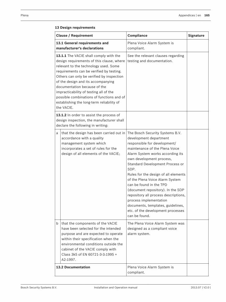
13 Design requirements
Clause / Requirement Compliance Signature
13.1 General requirements andmanufacturer's declarations
Plena Voice Alarm System iscompliant.
13.1.1 The VACIE shall comply with thedesign requirements of this clause, whererelevant to the technology used. Somerequirements can be verified by testing.Others can only be verified by inspectionof the design and its accompanyingdocumentation because of theimpracticability of testing all of thepossible combinations of functions and ofestablishing the long-term reliability ofthe VACIE.
See the relevant clauses regardingtesting and documentation.
13.1.2 In order to assist the process ofdesign inspection, the manufacturer shalldeclare the following in writing:
a that the design has been carried out inaccordance with a qualitymanagement system whichincorporates a set of rules for thedesign of all elements of the VACIE;
The Bosch Security Systems B.V.development departmentresponsible for development/maintenance of the Plena VoiceAlarm System works according itsown development process,Standard Development Process orSDP.Rules for the design of all elementsof the Plena Voice Alarm Systemcan be found in the TPD(document repository). In the SDPrepository all process descriptions,process implementationdocuments, templates, guidelines,etc. of the development processescan be found.
b that the components of the VACIEhave been selected for the intendedpurpose and are expected to operatewithin their specification when theenvironmental conditions outside thecabinet of the VACIE comply withClass 3k5 of EN 60721-3-3:1995 +A2:1997.
The Plena Voice Alarm System wasdesigned as a compliant voicealarm system.
13.2 Documentation Plena Voice Alarm System iscompliant.
Plena Appendices | en 165
Bosch Security Systems B.V. Installation and Operation manual 2013.07 | V2.0 |
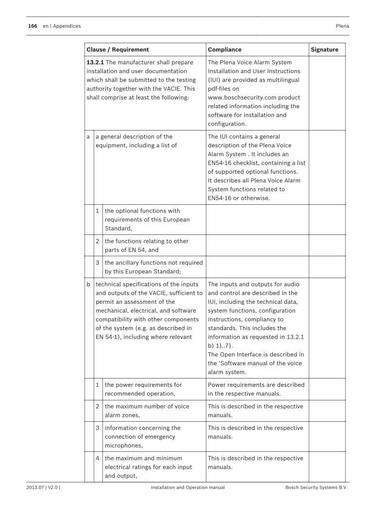
Clause / Requirement Compliance Signature
13.2.1 The manufacturer shall prepareinstallation and user documentationwhich shall be submitted to the testingauthority together with the VACIE. Thisshall comprise at least the following:
The Plena Voice Alarm SystemInstallation and User Instructions(IUI) are provided as multilingualpdf‑files onwww.boschsecurity.com productrelated information including thesoftware for installation andconfiguration.
a a general description of theequipment, including a list of
The IUI contains a generaldescription of the Plena VoiceAlarm System . It includes anEN54‑16 checklist, containing a listof supported optional functions.It describes all Plena Voice AlarmSystem functions related toEN54-16 or otherwise.
1 the optional functions withrequirements of this EuropeanStandard,
2 the functions relating to otherparts of EN 54, and
3 the ancillary functions not requiredby this European Standard;
b technical specifications of the inputsand outputs of the VACIE, sufficient topermit an assessment of themechanical, electrical, and softwarecompatibility with other componentsof the system (e.g. as described inEN 54‑1), including where relevant
The inputs and outputs for audioand control are described in theIUI, including the technical data,system functions, configurationinstructions, compliancy tostandards. This includes theinformation as requested in 13.2.1b) 1)..7).The Open Interface is described inthe ‘Software manual of the voicealarm system.
1 the power requirements forrecommended operation,
Power requirements are describedin the respective manuals.
2 the maximum number of voicealarm zones,
This is described in the respectivemanuals.
3 information concerning theconnection of emergencymicrophones,
This is described in the respectivemanuals.
4 the maximum and minimumelectrical ratings for each inputand output,
This is described in the respectivemanuals.
166 en | Appendices Plena
2013.07 | V2.0 | Installation and Operation manual Bosch Security Systems B.V.
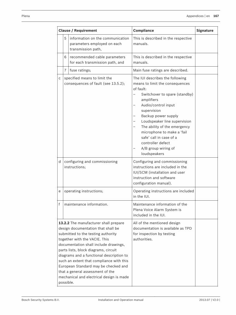
Clause / Requirement Compliance Signature
5 information on the communicationparameters employed on eachtransmission path,
This is described in the respectivemanuals.
6 recommended cable parametersfor each transmission path, and
This is described in the respectivemanuals.
7 fuse ratings; Main fuse ratings are described.
c specified means to limit theconsequences of fault (see 13.5.2);
The IUI describes the followingmeans to limit the consequencesof fault:– Switchover to spare (standby)
amplifiers– Audio/control input
supervision– Backup power supply– Loudspeaker line supervision– The ability of the emergency
microphone to make a ‘failsafe’ call in case of acontroller defect
– A/B group wiring ofloudspeakers
d configuring and commissioninginstructions;
Configuring and commissioninginstructions are included in theIUI/SCM (installation and userinstruction and softwareconfiguration manual).
e operating instructions; Operating instructions are includedin the IUI.
f maintenance information. Maintenance information of thePlena Voice Alarm System isincluded in the IUI.
13.2.2 The manufacturer shall preparedesign documentation that shall besubmitted to the testing authoritytogether with the VACIE. Thisdocumentation shall include drawings,parts lists, block diagrams, circuitdiagrams and a functional description tosuch an extent that compliance with thisEuropean Standard may be checked andthat a general assessment of themechanical and electrical design is madepossible.
All of the mentioned designdocumentation is available as TPDfor inspection by testingauthorities.
Plena Appendices | en 167
Bosch Security Systems B.V. Installation and Operation manual 2013.07 | V2.0 |
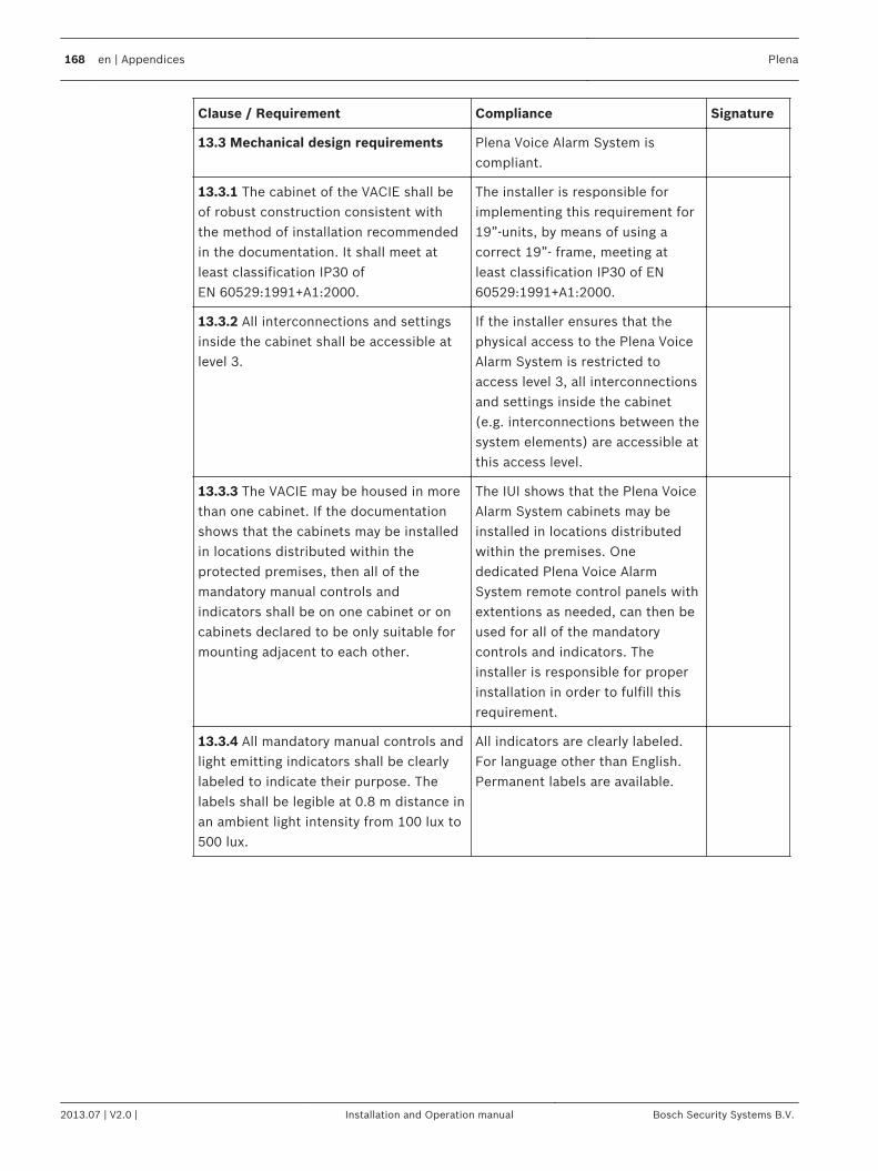
Clause / Requirement Compliance Signature
13.3 Mechanical design requirements Plena Voice Alarm System iscompliant.
13.3.1 The cabinet of the VACIE shall beof robust construction consistent withthe method of installation recommendedin the documentation. It shall meet atleast classification IP30 ofEN 60529:1991+A1:2000.
The installer is responsible forimplementing this requirement for19”-units, by means of using acorrect 19”- frame, meeting atleast classification IP30 of EN60529:1991+A1:2000.
13.3.2 All interconnections and settingsinside the cabinet shall be accessible atlevel 3.
If the installer ensures that thephysical access to the Plena VoiceAlarm System is restricted toaccess level 3, all interconnectionsand settings inside the cabinet(e.g. interconnections between thesystem elements) are accessible atthis access level.
13.3.3 The VACIE may be housed in morethan one cabinet. If the documentationshows that the cabinets may be installedin locations distributed within theprotected premises, then all of themandatory manual controls andindicators shall be on one cabinet or oncabinets declared to be only suitable formounting adjacent to each other.
The IUI shows that the Plena VoiceAlarm System cabinets may beinstalled in locations distributedwithin the premises. Onededicated Plena Voice AlarmSystem remote control panels withextentions as needed, can then beused for all of the mandatorycontrols and indicators. Theinstaller is responsible for properinstallation in order to fulfill thisrequirement.
13.3.4 All mandatory manual controls andlight emitting indicators shall be clearlylabeled to indicate their purpose. Thelabels shall be legible at 0.8 m distance inan ambient light intensity from 100 lux to500 lux.
All indicators are clearly labeled.For language other than English.Permanent labels are available.
168 en | Appendices Plena
2013.07 | V2.0 | Installation and Operation manual Bosch Security Systems B.V.
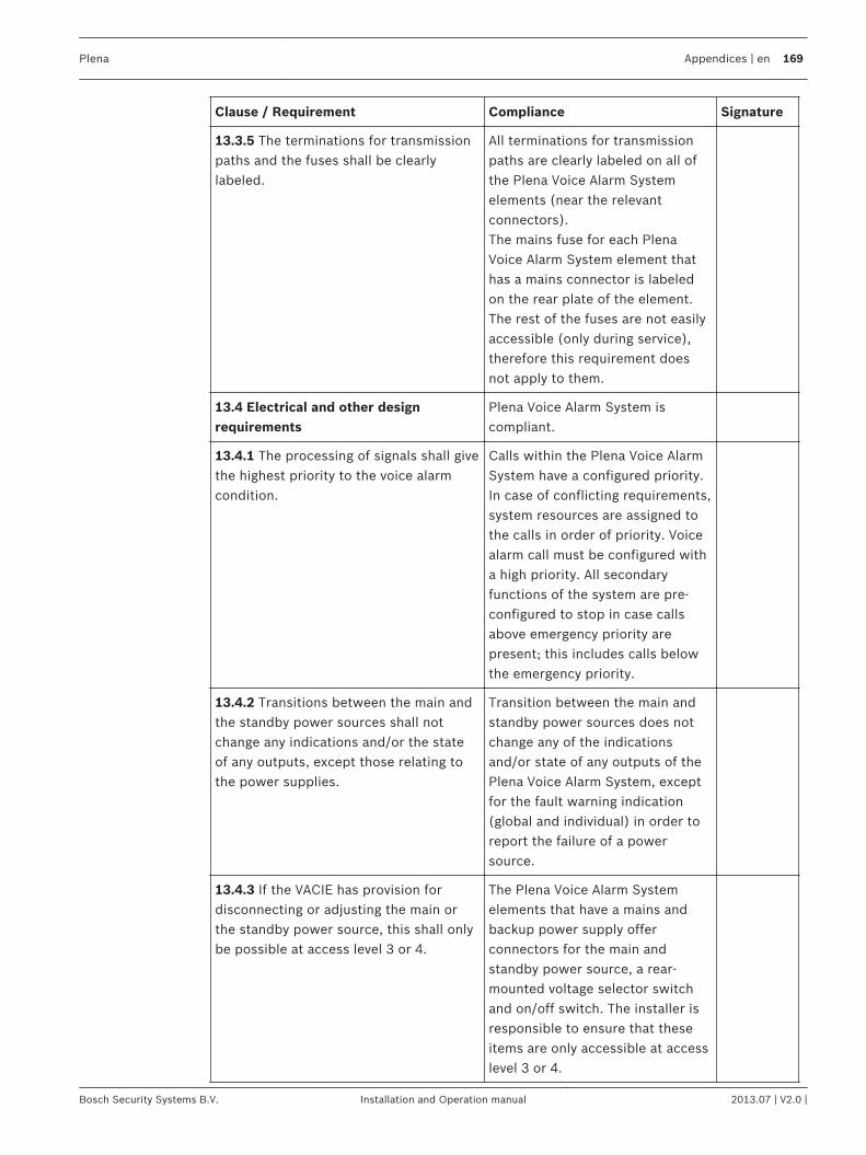
Clause / Requirement Compliance Signature
13.3.5 The terminations for transmissionpaths and the fuses shall be clearlylabeled.
All terminations for transmissionpaths are clearly labeled on all ofthe Plena Voice Alarm Systemelements (near the relevantconnectors).The mains fuse for each PlenaVoice Alarm System element thathas a mains connector is labeledon the rear plate of the element.The rest of the fuses are not easilyaccessible (only during service),therefore this requirement doesnot apply to them.
13.4 Electrical and other designrequirements
Plena Voice Alarm System iscompliant.
13.4.1 The processing of signals shall givethe highest priority to the voice alarmcondition.
Calls within the Plena Voice AlarmSystem have a configured priority.In case of conflicting requirements,system resources are assigned tothe calls in order of priority. Voicealarm call must be configured witha high priority. All secondaryfunctions of the system are pre-configured to stop in case callsabove emergency priority arepresent; this includes calls belowthe emergency priority.
13.4.2 Transitions between the main andthe standby power sources shall notchange any indications and/or the stateof any outputs, except those relating tothe power supplies.
Transition between the main andstandby power sources does notchange any of the indicationsand/or state of any outputs of thePlena Voice Alarm System, exceptfor the fault warning indication(global and individual) in order toreport the failure of a powersource.
13.4.3 If the VACIE has provision fordisconnecting or adjusting the main orthe standby power source, this shall onlybe possible at access level 3 or 4.
The Plena Voice Alarm Systemelements that have a mains andbackup power supply offerconnectors for the main andstandby power source, a rear-mounted voltage selector switchand on/off switch. The installer isresponsible to ensure that theseitems are only accessible at accesslevel 3 or 4.
Plena Appendices | en 169
Bosch Security Systems B.V. Installation and Operation manual 2013.07 | V2.0 |
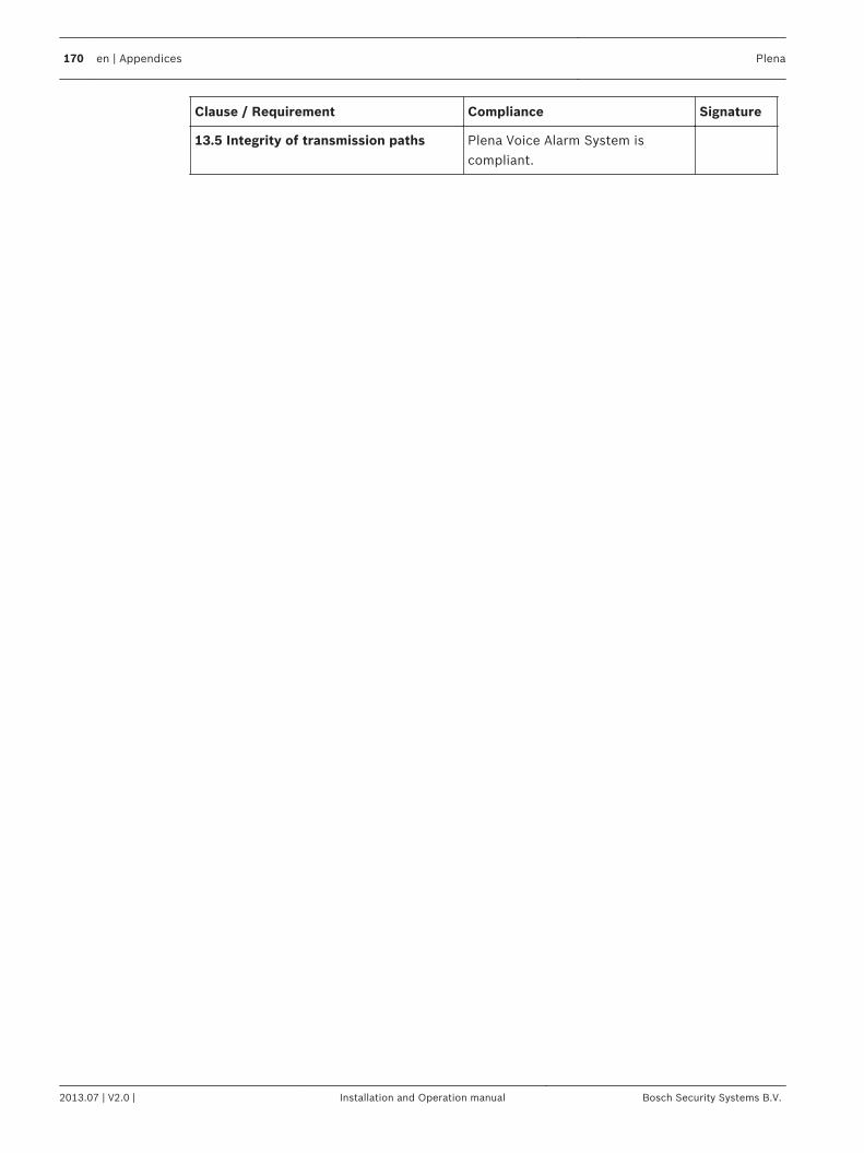
Clause / Requirement Compliance Signature
13.5 Integrity of transmission paths Plena Voice Alarm System iscompliant.
170 en | Appendices Plena
2013.07 | V2.0 | Installation and Operation manual Bosch Security Systems B.V.
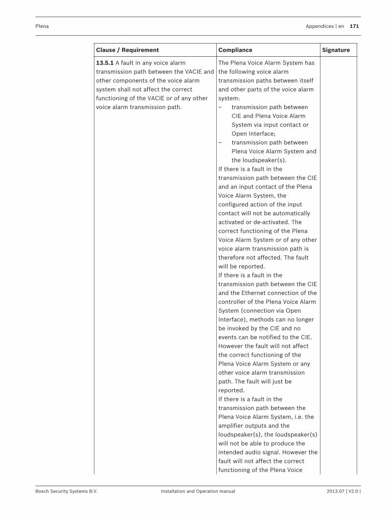
Clause / Requirement Compliance Signature
13.5.1 A fault in any voice alarmtransmission path between the VACIE andother components of the voice alarmsystem shall not affect the correctfunctioning of the VACIE or of any othervoice alarm transmission path.
The Plena Voice Alarm System hasthe following voice alarmtransmission paths between itselfand other parts of the voice alarmsystem:– transmission path between
CIE and Plena Voice AlarmSystem via input contact orOpen Interface;
– transmission path betweenPlena Voice Alarm System andthe loudspeaker(s).
If there is a fault in thetransmission path between the CIEand an input contact of the PlenaVoice Alarm System, theconfigured action of the inputcontact will not be automaticallyactivated or de-activated. Thecorrect functioning of the PlenaVoice Alarm System or of any othervoice alarm transmission path istherefore not affected. The faultwill be reported.If there is a fault in thetransmission path between the CIEand the Ethernet connection of thecontroller of the Plena Voice AlarmSystem (connection via OpenInterface), methods can no longerbe invoked by the CIE and noevents can be notified to the CIE.However the fault will not affectthe correct functioning of thePlena Voice Alarm System or anyother voice alarm transmissionpath. The fault will just bereported.If there is a fault in thetransmission path between thePlena Voice Alarm System, i.e. theamplifier outputs and theloudspeaker(s), the loudspeaker(s)will not be able to produce theintended audio signal. However thefault will not affect the correctfunctioning of the Plena Voice
Plena Appendices | en 171
Bosch Security Systems B.V. Installation and Operation manual 2013.07 | V2.0 |
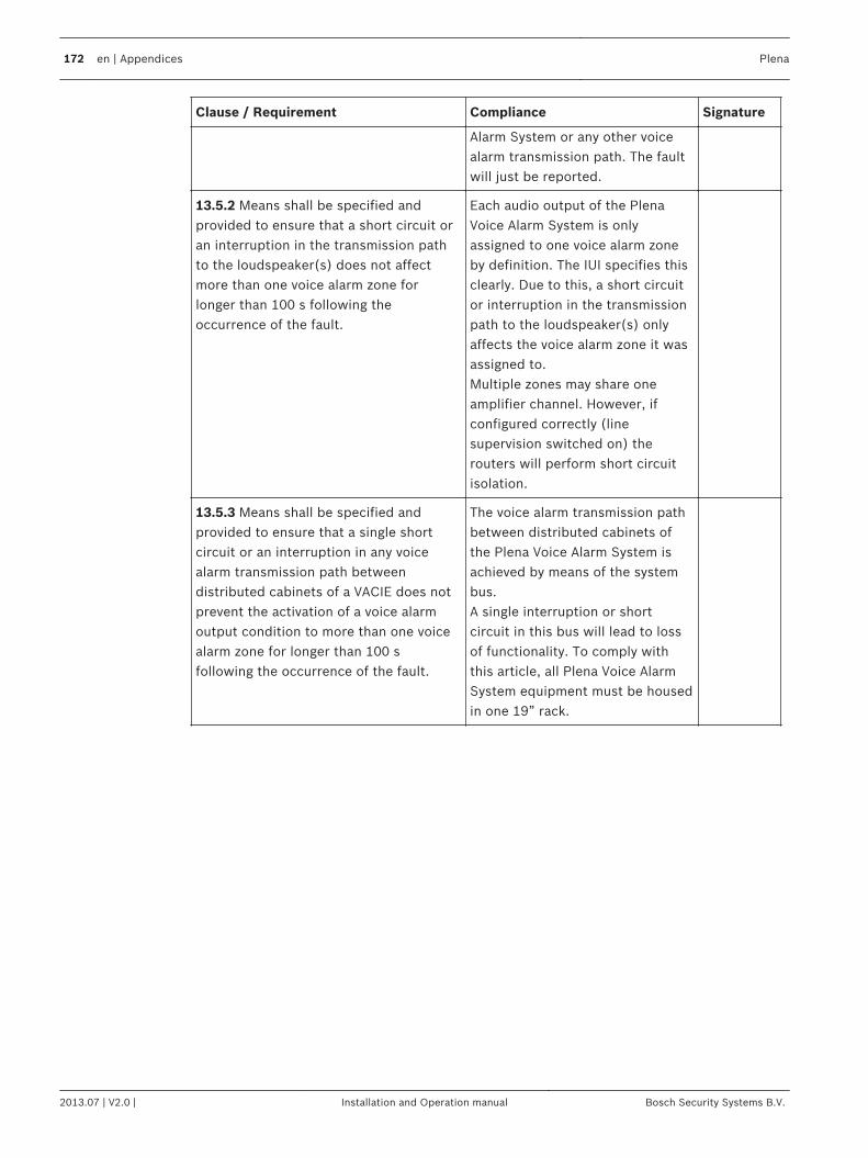
Clause / Requirement Compliance Signature
Alarm System or any other voicealarm transmission path. The faultwill just be reported.
13.5.2 Means shall be specified andprovided to ensure that a short circuit oran interruption in the transmission pathto the loudspeaker(s) does not affectmore than one voice alarm zone forlonger than 100 s following theoccurrence of the fault.
Each audio output of the PlenaVoice Alarm System is onlyassigned to one voice alarm zoneby definition. The IUI specifies thisclearly. Due to this, a short circuitor interruption in the transmissionpath to the loudspeaker(s) onlyaffects the voice alarm zone it wasassigned to.Multiple zones may share oneamplifier channel. However, ifconfigured correctly (linesupervision switched on) therouters will perform short circuitisolation.
13.5.3 Means shall be specified andprovided to ensure that a single shortcircuit or an interruption in any voicealarm transmission path betweendistributed cabinets of a VACIE does notprevent the activation of a voice alarmoutput condition to more than one voicealarm zone for longer than 100 sfollowing the occurrence of the fault.
The voice alarm transmission pathbetween distributed cabinets ofthe Plena Voice Alarm System isachieved by means of the systembus.A single interruption or shortcircuit in this bus will lead to lossof functionality. To comply withthis article, all Plena Voice AlarmSystem equipment must be housedin one 19” rack.
172 en | Appendices Plena
2013.07 | V2.0 | Installation and Operation manual Bosch Security Systems B.V.

Clause / Requirement Compliance Signature
13.5.4 If the VACIE is designed to be usedwith a power supply (item L of Figure 1 ofEN 54-1) contained in a separate cabinet,then an interface shall be provided for atleast two voice alarm transmission pathsto the power supply, such that a shortcircuit or an interruption in one does notaffect the other.
If a 19”-cabinet (rack) or adjacentcabinets provide enough space forthe battery and/or charger, theinstaller can install the completePSE (power supply equipment) asreferred in EN54-4 in one cabinet.In that case this requirement is notapplicable.In case the installer installs thebackup part of the PSE (batteryand charger) in a separate cabinet,Plena Voice Alarm System providesa separate (monitored) DC-backupconnection on the Plena VoiceAlarm System units. This impliesthat a Plena Voice Alarm Systeminstallation will always have twoseparate voice alarm transmissionpaths to the power supply: one formains and one for DC backup.Both will not influence each other(except for current drawn).It is the responsibility of theinstaller to let the installationcomply with this requirement.
13.6 Accessibility of indications andcontrols
Plena Voice Alarm System iscompliant.
Plena Appendices | en 173
Bosch Security Systems B.V. Installation and Operation manual 2013.07 | V2.0 |
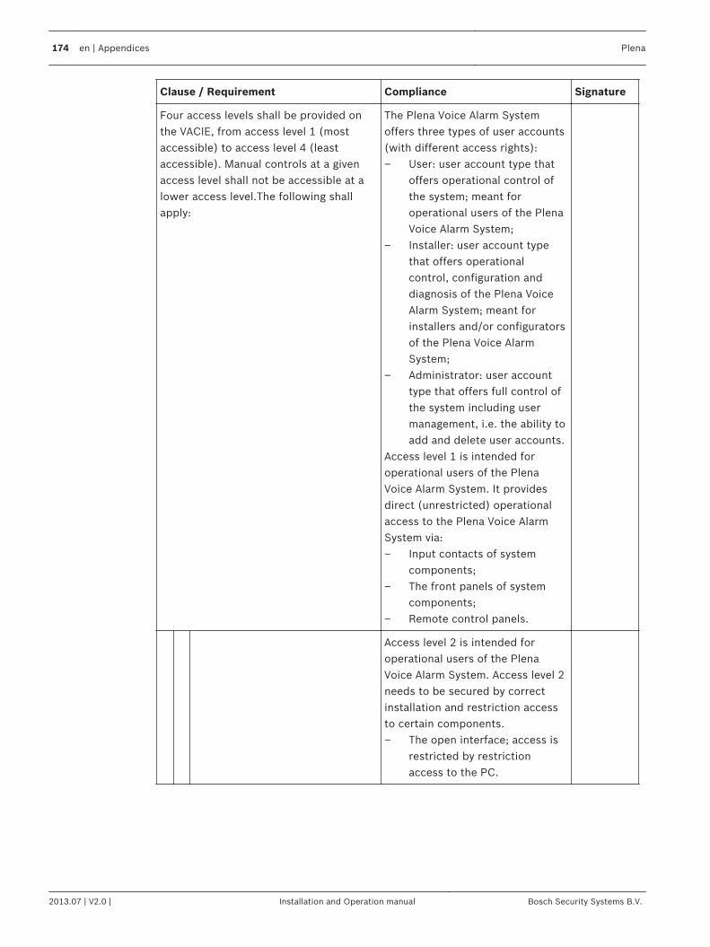
Clause / Requirement Compliance Signature
Four access levels shall be provided onthe VACIE, from access level 1 (mostaccessible) to access level 4 (leastaccessible). Manual controls at a givenaccess level shall not be accessible at alower access level.The following shallapply:
The Plena Voice Alarm Systemoffers three types of user accounts(with different access rights):– User: user account type that
offers operational control ofthe system; meant foroperational users of the PlenaVoice Alarm System;
– Installer: user account typethat offers operationalcontrol, configuration anddiagnosis of the Plena VoiceAlarm System; meant forinstallers and/or configuratorsof the Plena Voice AlarmSystem;
– Administrator: user accounttype that offers full control ofthe system including usermanagement, i.e. the ability toadd and delete user accounts.
Access level 1 is intended foroperational users of the PlenaVoice Alarm System. It providesdirect (unrestricted) operationalaccess to the Plena Voice AlarmSystem via:– Input contacts of system
components;– The front panels of system
components;– Remote control panels.
Access level 2 is intended foroperational users of the PlenaVoice Alarm System. Access level 2needs to be secured by correctinstallation and restriction accessto certain components.– The open interface; access is
restricted by restrictionaccess to the PC.
174 en | Appendices Plena
2013.07 | V2.0 | Installation and Operation manual Bosch Security Systems B.V.
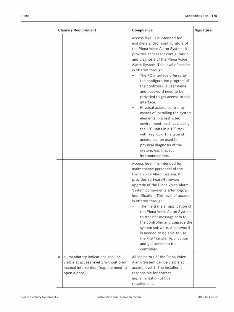
Clause / Requirement Compliance Signature
Access level 3 is intended forinstallers and/or configurators ofthe Plena Voice Alarm System. Itprovides access for configurationand diagnosis of the Plena VoiceAlarm System. This level of accessis offered through:– The PC interface offered by
the configuration program ofthe controller. A user nameand password need to beprovided to get access to thisinterface.
– Physical access control bymeans of installing the systemelements in a restrictedenvironment, such as placingthe 19”-units in a 19”-rackwith key lock. This type ofaccess can be used forphysical diagnosis of thesystem, e.g. inspectinterconnections.
Access level 4 is intended formaintenance personnel of thePlena Voice Alarm System. Itprovides software/firmwareupgrade of the Plena Voice AlarmSystem components after logicalidentification. This level of accessis offered through:– The file transfer application of
the Plena Voice Alarm Systemto transfer message sets tothe controller and upgrade thesystem software. A passwordis needed to be able to usethe File Transfer Applicationand get access to thecontroller.
a all mandatory indications shall bevisible at access level 1 without priormanual intervention (e.g. the need toopen a door);
All indicators of the Plena VoiceAlarm System can be visible ataccess level 1. The installer isresponsible for correctimplementation of thisrequirement.
Plena Appendices | en 175
Bosch Security Systems B.V. Installation and Operation manual 2013.07 | V2.0 |
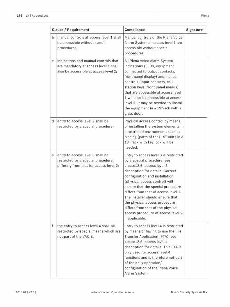
Clause / Requirement Compliance Signature
b manual controls at access level 1 shallbe accessible without specialprocedures;
Manual controls of the Plena VoiceAlarm System at access level 1 areaccessible without specialprocedures.
c indications and manual controls thatare mandatory at access level 1 shallalso be accessible at access level 2;
All Plena Voice Alarm Systemindications (LEDs, equipmentconnected to output contacts,front panel display) and manualcontrols (input contacts, callstation keys, front panel menus)that are accessible at access level1 will also be accessible at accesslevel 2. It may be needed to iinstalthe equipment in a 19”rack with aglass door.
d entry to access level 2 shall berestricted by a special procedure;
Physical access control by meansof installing the system elements ina restricted environment, such asplacing (parts of the) 19”-units in a19”-rack with key lock will beneeded.
e entry to access level 3 shall berestricted by a special procedure,differing from that for access level 2;
Entry to access level 3 is restrictedby a special procedure, seeclause13.6, access level 3description for details. Correctconfiguration and installation(physical access control) willensure that the special procedurediffers from that of access level 2.The installer should ensure thatthe physical access procedurediffers from that of the physicalaccess procedure of access level 2,if applicable.
f the entry to access level 4 shall berestricted by special means which arenot part of the VACIE.
Entry to access level 4 is restrictedby means of having to use the FileTransfer Application (FTA), seeclause13.6, access level 4description for details. This FTA isonly used for access level 4functions and is therefore not partof the daily operation/configuration of the Plena VoiceAlarm System.
176 en | Appendices Plena
2013.07 | V2.0 | Installation and Operation manual Bosch Security Systems B.V.
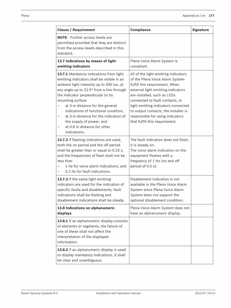
Clause / Requirement Compliance Signature
NOTE - Further access levels arepermitted provided that they are distinctfrom the access levels described in thisstandard.
13.7 Indications by means of light-emitting indicators
Plena Voice Alarm System iscompliant.
13.7.1 Mandatory indications from lightemitting indicators shall be visible in anambient light intensity up to 500 lux, atany angle up to 22.5° from a line throughthe indicator perpendicular to itsmounting surface– at 3 m distance for the general
indications of functional condition,– at 3 m distance for the indication of
the supply of power, and– at 0.8 m distance for other
indications.
All of the light emitting indicatorsof the Plena Voice Alarm Systemfulfill this requirement. Whenexternal light emitting indicatorsare installed, such as LEDsconnected to fault contacts, orlight emitting indicators connectedto output contacts, the installer isresponsible for using indicatorsthat fulfill this requirement.
13.7.2 If flashing indications are used,both the on period and the off periodshall be greater than or equal to 0.25 s,and the frequencies of flash shall not beless than– 1 Hz for voice alarm indications, and– 0.2 Hz for fault indications.
The fault indication does not flash;it is steady on.The voice alarm indication on theequipment flashes with afrequency of 1 Hz (on and offperiod of 0.5 s).
13.7.3 If the same light emittingindicators are used for the indication ofspecific faults and disablements, faultindications shall be flashing anddisablement indications shall be steady.
Disablement indication is notavailable in the Plena Voice AlarmSystem since Plena Voice AlarmSystem does not support theoptional disablement condition.
13.8 Indications on alphanumericdisplays
Plena Voice Alarm System does nothave an alphanumeric display.
13.8.1 If an alphanumeric display consistsof elements or segments, the failure ofone of these shall not affect theinterpretation of the displayedinformation.
13.8.2 If an alphanumeric display is usedto display mandatory indications, it shallbe clear and unambiguous.
Plena Appendices | en 177
Bosch Security Systems B.V. Installation and Operation manual 2013.07 | V2.0 |
Clause / Requirement Compliance Signature
13.8.3 Mandatory indications on analphanumeric display shall be legible forat least one hour following the display ofa new indication of the voice alarmcondition and at least 5 minutes for faultor disablement conditions, at 0,8 mdistance, in ambient light intensities from5 to 500 lux, at any angle from the normalto the plane of the display up to– 22.5º when viewed from each side,
and– 15º when viewed from above and
below.
13.9 Indication colors Plena Voice Alarm System iscompliant.
13.9.1 The colors of the general andspecific indications from light emittingindicators shall be
a red for indications of voice alarms; The system status LED of PlenaVoice Alarm System call stations ison (red) when the system is in thevoice alarm condition. Theindicators on the controller andremote control panels are red. Theinstaller is responsible forconnecting a red light emittingindicator to a ‘Visual EVACindicator’ output contact of thePlena Voice Alarm System. All zoneindicators in emergency mode arered.
178 en | Appendices Plena
2013.07 | V2.0 | Installation and Operation manual Bosch Security Systems B.V.
Clause / Requirement Compliance Signature
b yellow for indications of– fault warnings, and– disablements, or
The Fault LED of Plena Voice AlarmSystem controller, routers andremote control panels are yellow.Additionally the call stationindicator is also yellow when thesystem is in the fault warningcondition. The installer isresponsible for connecting a yellowlight emitting indicator to the‘Visual fault indicator’ outputcontact (or another output contactconfigured for this function).Disablement indication is notavailable in the Plena Voice AlarmSystem since Plena Voice AlarmSystem does not support theoptional disablement condition.
c green for the indication that the VACIEis supplied with power.
All light emitting indicators of thePlena Voice Alarm System thatindicate power supply are green.
NOTE - Where voice alarm automaticmessage status indicators are provided, itmay be advantageous to indicate thedifference between evacuation and alertmessages. In this case, red will be usedfor emergency messages and yellow maybe used for alert messages.
13.9.2 The use of different colors is notnecessary for indications onalphanumeric displays. However, ifdifferent colors are used for differentindications, the colors used shall be asspecified in 13.9.1.
The Plena Voice Alarm System donot use alphanumeric displays.
13.10 Audible indications Plena Voice Alarm System iscompliant.
Plena Appendices | en 179
Bosch Security Systems B.V. Installation and Operation manual 2013.07 | V2.0 |
Clause / Requirement Compliance Signature
13.10.1 Audible indicators shall be part ofthe VACIE. The same device may be usedfor voice alarm zone activated and faultwarning indications.
The monitor loudspeaker of theVoice Alarm System is used forboth fault warning (continuoustone) and emergency condition(intermittent tone). If additionalsounders are desired, the installeris responsible for connectingsounders to output contactsconfigured as ‘EVAC indicator’ or‘fault indicator’. The installer maydecide to connect both the voicealarm activated output contact aswell as the fault warning conditionactivated output contact to thesame sounder.
13.10.2 The minimum sound pressurelevel, measured under anechoicconditions at a distance of 1 m, with anyaccess door(s) on the VACIE closed, shallbe– 60 dBA for the voice alarm condition,
and– 50 dBA for the fault warning
condition.
The installer is responsible foreither connecting a sounder thatcomplies with this clause outsideor inside the rack, or install thesystem in a rack that is sufficientlyacoustic transparent. Advice is toinstall a remote control panel, allremote control panels and thefireman’s panel have a monitorspeaker.
13.11 Indicator testing Plena Voice Alarm System iscompliant.
All mandatory visible and audibleindicators shall be testable by a manualoperation at access level 1 or 2.
Plena Voice Alarm System providesan ‘Indicator test’ button. Whenactivated all indications the systemand all its connected routers areswitched on to visually check theindicators. The remote controlpanels have their own test button.The indicators of that remotecontrol panel and connectedextensions will light up.The installer is responsible formaking indicators that areconnected to control outputcontacts testable.
13.12 Audio performance Plena Voice Alarm System iscompliant.
13.12.1 Output power
180 en | Appendices Plena
2013.07 | V2.0 | Installation and Operation manual Bosch Security Systems B.V.
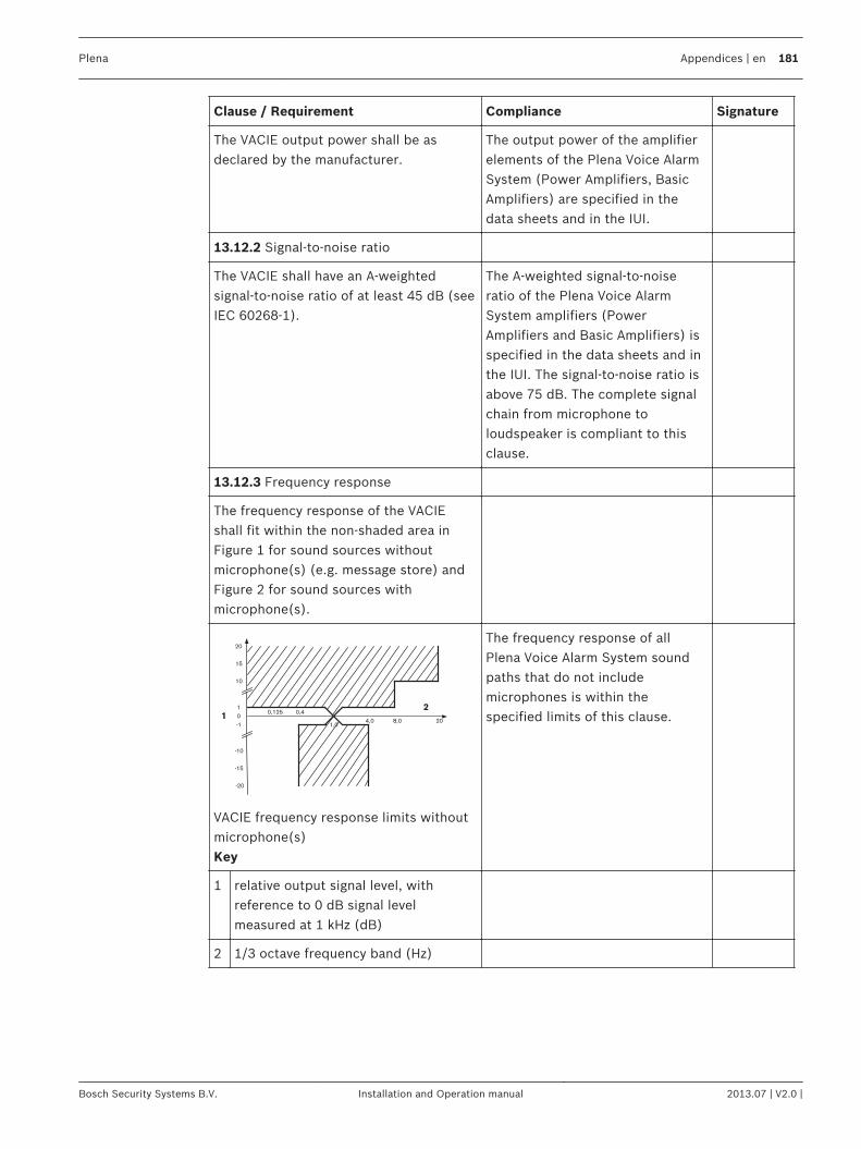
Clause / Requirement Compliance Signature
The VACIE output power shall be asdeclared by the manufacturer.
The output power of the amplifierelements of the Plena Voice AlarmSystem (Power Amplifiers, BasicAmplifiers) are specified in thedata sheets and in the IUI.
13.12.2 Signal-to-noise ratio
The VACIE shall have an A-weightedsignal-to-noise ratio of at least 45 dB (seeIEC 60268-1).
The A-weighted signal-to-noiseratio of the Plena Voice AlarmSystem amplifiers (PowerAmplifiers and Basic Amplifiers) isspecified in the data sheets and inthe IUI. The signal-to-noise ratio isabove 75 dB. The complete signalchain from microphone toloudspeaker is compliant to thisclause.
13.12.3 Frequency response
The frequency response of the VACIEshall fit within the non-shaded area inFigure 1 for sound sources withoutmicrophone(s) (e.g. message store) andFigure 2 for sound sources withmicrophone(s).
24,0 8,0 20
-10
0,4
-20
-15
0
1
10
-1
0,125
15
20
11,0
VACIE frequency response limits withoutmicrophone(s)Key
The frequency response of allPlena Voice Alarm System soundpaths that do not includemicrophones is within thespecified limits of this clause.
1 relative output signal level, withreference to 0 dB signal levelmeasured at 1 kHz (dB)
2 1/3 octave frequency band (Hz)
Plena Appendices | en 181
Bosch Security Systems B.V. Installation and Operation manual 2013.07 | V2.0 |
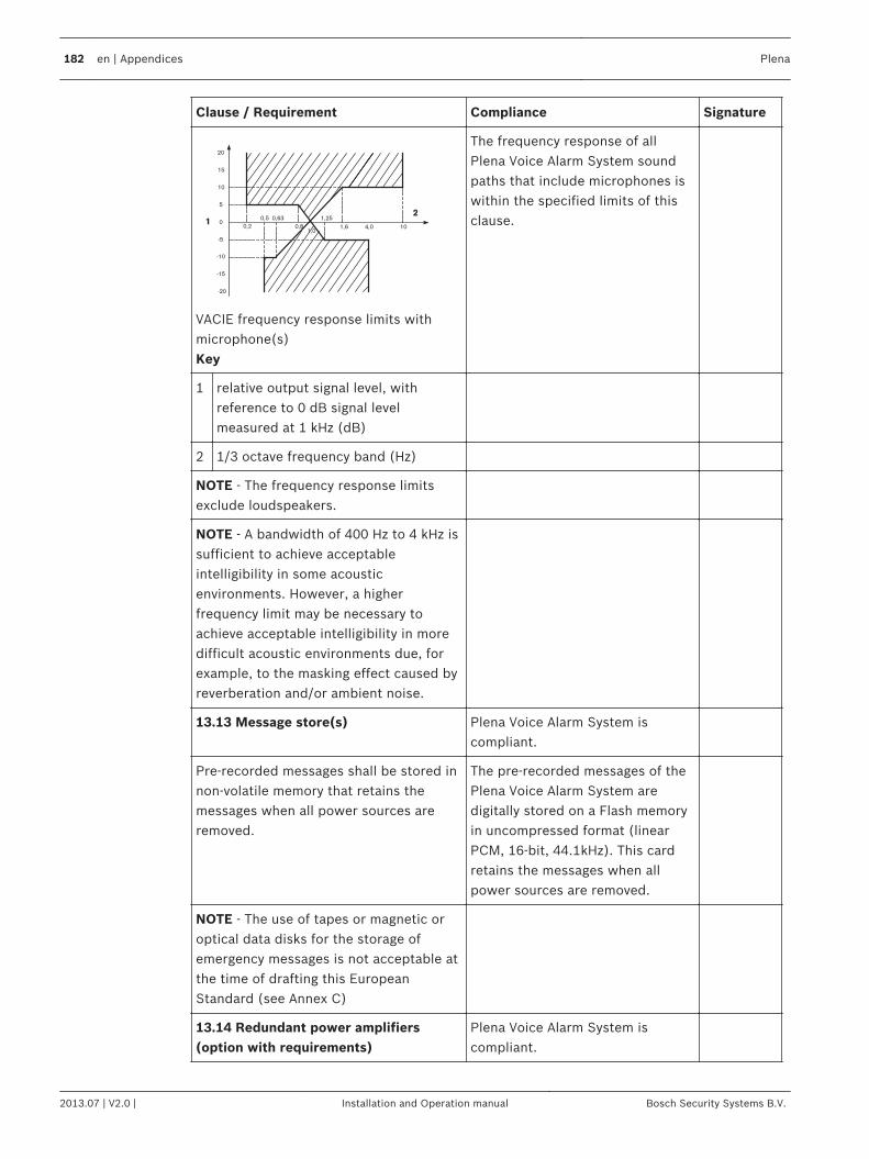
Clause / Requirement Compliance Signature
24,0 10
-10
0,5
-20
-15
0
5
10
-5
0,2
15
20
11,0
0,63
0,8 1,6
1,25
VACIE frequency response limits withmicrophone(s)Key
The frequency response of allPlena Voice Alarm System soundpaths that include microphones iswithin the specified limits of thisclause.
1 relative output signal level, withreference to 0 dB signal levelmeasured at 1 kHz (dB)
2 1/3 octave frequency band (Hz)
NOTE - The frequency response limitsexclude loudspeakers.
NOTE - A bandwidth of 400 Hz to 4 kHz issufficient to achieve acceptableintelligibility in some acousticenvironments. However, a higherfrequency limit may be necessary toachieve acceptable intelligibility in moredifficult acoustic environments due, forexample, to the masking effect caused byreverberation and/or ambient noise.
13.13 Message store(s) Plena Voice Alarm System iscompliant.
Pre-recorded messages shall be stored innon-volatile memory that retains themessages when all power sources areremoved.
The pre-recorded messages of thePlena Voice Alarm System aredigitally stored on a Flash memoryin uncompressed format (linearPCM, 16-bit, 44.1kHz). This cardretains the messages when allpower sources are removed.
NOTE - The use of tapes or magnetic oroptical data disks for the storage ofemergency messages is not acceptable atthe time of drafting this EuropeanStandard (see Annex C)
13.14 Redundant power amplifiers(option with requirements)
Plena Voice Alarm System iscompliant.
182 en | Appendices Plena
2013.07 | V2.0 | Installation and Operation manual Bosch Security Systems B.V.
Clause / Requirement Compliance Signature
13.14.1 The VACIE may have provision forat least one spare power amplifier. In thiscase:
The Plena Voice Alarm System hasa minimum of one main amplifierand one call amplifier. It has amaximum of one main amplifier perrouter and one spare amplifier perrouter (including the router built inthe controller). Each router of thePlena Voice Alarm System has aninput for connecting a spareamplifier channel. It also containsswitch-over relays to switch theloudspeaker load from the originalamplifier output to the spareamplifier output. A spare amplifierchannel assignment is configurableto multiple routers (in singlechannel mode).
a in the event of the failure of a poweramplifier, the faulty amplifier shall becapable of being replacedautomatically with a spare amplifierwithin 10 s of the fault beingdetected;
After fault detection of an amplifierall loudspeaker lines are switchedautomatically to the spare amplifier(if connected and configured)within 10 s.
NOTE - This can be achieved, forexample, by switching or by permanentlyconnected parallel amplifiers.
b the spare power amplifier(s) shallhave at least the same functionalityand output power as the replacedamplifier.
Each router of the Plena VoiceAlarm System has a spare amplifierinput. The installer is responsiblefor proper installation andconfiguration of the amplifiers tomatch amplifier power and load.Plena Voice Alarm System takescare of input signal switching tothe spare amplifier channel. Thisway the spare power amplifier(s)will have the same functionalityand output power as the replacedamplifier.
Plena Appendices | en 183
Bosch Security Systems B.V. Installation and Operation manual 2013.07 | V2.0 |
Clause / Requirement Compliance Signature
13.14.2 Every fault of an amplifier shallbe indicated by a general fault warningindicator as specified in .2
All Plena Voice Alarm Systempower amplifiers are supervised foroverload, overheating, short-circuit, ground short and amplifierdefect. If any such fault is detectedit is indicated both by means of thegeneral fault warning indicator andby means of an individual faultLED.
13.14.3 Supervision of the spareamplifier(s) shall be maintained duringthe functional condition whilst the VACIEis powered by either the mains orstandby power supplies.
The spare amplifiers arecontinuously supervised,supervision is identical to the main(call) amplifier.The supervision is active whilst thePlena Voice Alarm System ispowered by either the mains orstandby power supplies.Note: the spare amplifiers in theVoice Alarm System are used asbackground music amplifiers (if soconfigured).
14 Additional design requirements for software controlled VACIE
Clause / Requirement Compliance Signature
14.1 General requirements andmanufacturer's declarations
Plena Voice Alarm System iscompliant.
In order to fulfill requirements of thisEuropean Standard the VACIE maycontain elements which are controlled bysoftware. In this case, the VACIE shallcomply with the requirements of Clause13 Design requirements and this clausewhere relevant to the technology used.
The Plena Voice Alarm System iscentrally controlled by thesoftware running on the controller.
14.2 Software documentation Plena Voice Alarm System iscompliant.
14.2.1 The manufacturer shall preparedocumentation that gives an overview ofthe software design, which shall besubmitted to the testing authoritytogether with the VACIE. Thisdocumentation shall be in sufficient detailfor the design to be inspected forcompliance with this European Standardand shall comprise at least the following:
The software designdocumentation is available fortesting authorities. It is insufficient detail for the design tobe inspected for compliance.
184 en | Appendices Plena
2013.07 | V2.0 | Installation and Operation manual Bosch Security Systems B.V.
Clause / Requirement Compliance Signature
a functional description, using a clearmethodology appropriate to thenature of the software, e.g. graphicalrepresentations of the system design,data flows and control flows andof themain program flow, including:
Software design documents areavailable and maintained.
1 a brief description of each moduleand the tasks it performs,
Architecture documents areavailable.
2 the way in which the modulesinteract,
Architecture and designdocuments are available.
3 the way in which the modules arecalled, including any interruptprocessing, and
Architecture and designdocuments are available.
4 the overall hierarchy of theprogram;
Architecture documents areavailable.
b a description of which areas ofmemory are used for the variouspurposes (e.g. the program, sitespecific data and running data);
Memory usage is described in thesystem architecture document.
c a description of how the softwareinteracts with the hardware of theVACIE.
Hardware software interaction isdesribed in a set of Hardware-Software Interface documentation.
Where dynamic memory management isemployed, a separation shall beimplemented between the program, sitespecific data and running data and thisshall be described in connection with themethod of memory allocation.
The program is located in separateFlash EPROMs that are reservedfor the program executable.The message data is stored on aseparate Flash EPROMs.
14.2.2 The manufacturer shall prepareand maintain detailed designdocumentation. This need not besubmitted to the testing authority butshall be available for inspection in amanner which respects themanufacturer's rights of confidentiality.This documentation shall comprise atleast the following:
The software design documentscontain detailed designdocumentation. Furthermore codecomments also contain detaileddesign documentation.
a a description of each module of theprogram, as it is implemented in thesource code of the program,containing:– the name of the module, and– the identification of the
author(s);
The Plena Voice Alarm Systemsoftware component descriptions(module descriptions) are availablefrom the software architecturedocuments. These documentscontain the names of thecomponents.
Plena Appendices | en 185
Bosch Security Systems B.V. Installation and Operation manual 2013.07 | V2.0 |
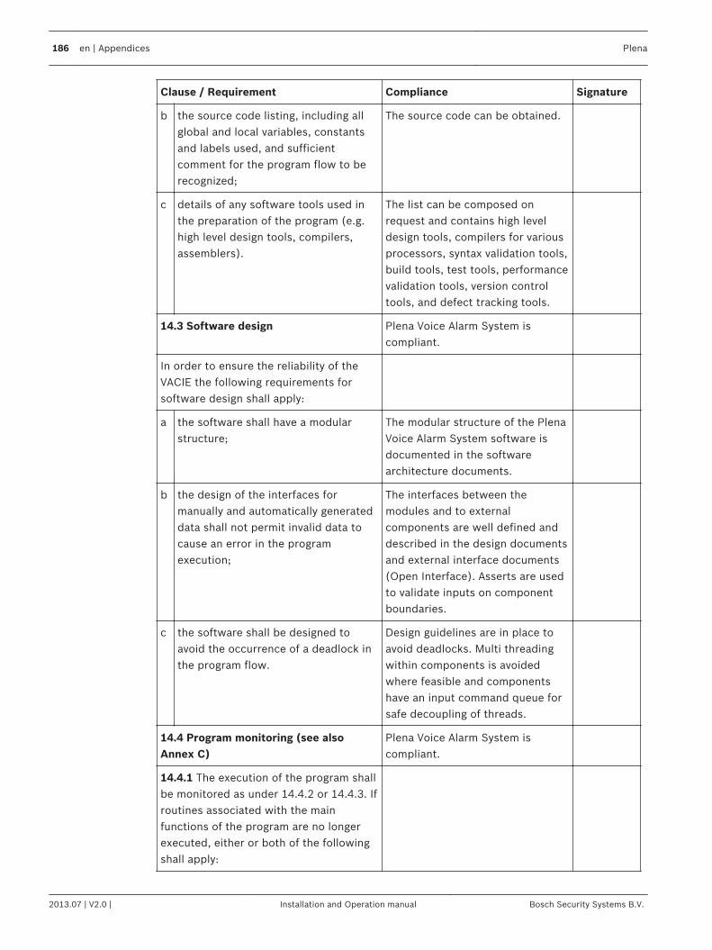
Clause / Requirement Compliance Signature
b the source code listing, including allglobal and local variables, constantsand labels used, and sufficientcomment for the program flow to berecognized;
The source code can be obtained.
c details of any software tools used inthe preparation of the program (e.g.high level design tools, compilers,assemblers).
The list can be composed onrequest and contains high leveldesign tools, compilers for variousprocessors, syntax validation tools,build tools, test tools, performancevalidation tools, version controltools, and defect tracking tools.
14.3 Software design Plena Voice Alarm System iscompliant.
In order to ensure the reliability of theVACIE the following requirements forsoftware design shall apply:
a the software shall have a modularstructure;
The modular structure of the PlenaVoice Alarm System software isdocumented in the softwarearchitecture documents.
b the design of the interfaces formanually and automatically generateddata shall not permit invalid data tocause an error in the programexecution;
The interfaces between themodules and to externalcomponents are well defined anddescribed in the design documentsand external interface documents(Open Interface). Asserts are usedto validate inputs on componentboundaries.
c the software shall be designed toavoid the occurrence of a deadlock inthe program flow.
Design guidelines are in place toavoid deadlocks. Multi threadingwithin components is avoidedwhere feasible and componentshave an input command queue forsafe decoupling of threads.
14.4 Program monitoring (see alsoAnnex C)
Plena Voice Alarm System iscompliant.
14.4.1 The execution of the program shallbe monitored as under 14.4.2 or 14.4.3. Ifroutines associated with the mainfunctions of the program are no longerexecuted, either or both of the followingshall apply:
186 en | Appendices Plena
2013.07 | V2.0 | Installation and Operation manual Bosch Security Systems B.V.
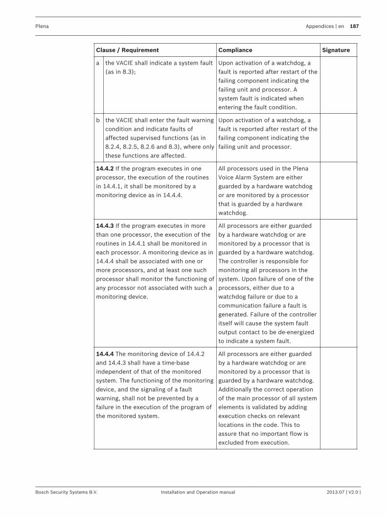
Clause / Requirement Compliance Signature
a the VACIE shall indicate a system fault(as in 8.3);
Upon activation of a watchdog, afault is reported after restart of thefailing component indicating thefailing unit and processor. Asystem fault is indicated whenentering the fault condition.
b the VACIE shall enter the fault warningcondition and indicate faults ofaffected supervised functions (as in8.2.4, 8.2.5, 8.2.6 and 8.3), where onlythese functions are affected.
Upon activation of a watchdog, afault is reported after restart of thefailing component indicating thefailing unit and processor.
14.4.2 If the program executes in oneprocessor, the execution of the routinesin 14.4.1, it shall be monitored by amonitoring device as in 14.4.4.
All processors used in the PlenaVoice Alarm System are eitherguarded by a hardware watchdogor are monitored by a processorthat is guarded by a hardwarewatchdog.
14.4.3 If the program executes in morethan one processor, the execution of theroutines in 14.4.1 shall be monitored ineach processor. A monitoring device as in14.4.4 shall be associated with one ormore processors, and at least one suchprocessor shall monitor the functioning ofany processor not associated with such amonitoring device.
All processors are either guardedby a hardware watchdog or aremonitored by a processor that isguarded by a hardware watchdog.The controller is responsible formonitoring all processors in thesystem. Upon failure of one of theprocessors, either due to awatchdog failure or due to acommunication failure a fault isgenerated. Failure of the controlleritself will cause the system faultoutput contact to be de-energizedto indicate a system fault.
14.4.4 The monitoring device of 14.4.2and 14.4.3 shall have a time-baseindependent of that of the monitoredsystem. The functioning of the monitoringdevice, and the signaling of a faultwarning, shall not be prevented by afailure in the execution of the program ofthe monitored system.
All processors are either guardedby a hardware watchdog or aremonitored by a processor that isguarded by a hardware watchdog.Additionally the correct operationof the main processor of all systemelements is validated by addingexecution checks on relevantlocations in the code. This toassure that no important flow isexcluded from execution.
Plena Appendices | en 187
Bosch Security Systems B.V. Installation and Operation manual 2013.07 | V2.0 |
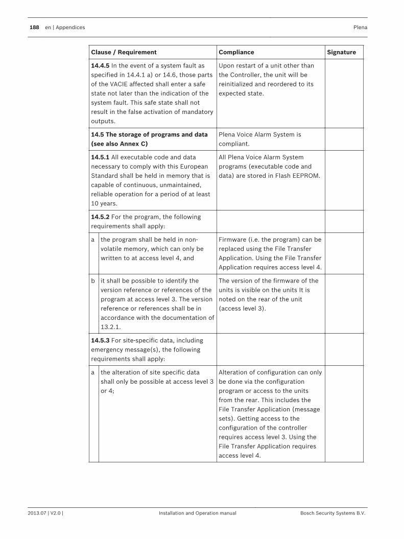
Clause / Requirement Compliance Signature
14.4.5 In the event of a system fault asspecified in 14.4.1 a) or 14.6, those partsof the VACIE affected shall enter a safestate not later than the indication of thesystem fault. This safe state shall notresult in the false activation of mandatoryoutputs.
Upon restart of a unit other thanthe Controller, the unit will bereinitialized and reordered to itsexpected state.
14.5 The storage of programs and data(see also Annex C)
Plena Voice Alarm System iscompliant.
14.5.1 All executable code and datanecessary to comply with this EuropeanStandard shall be held in memory that iscapable of continuous, unmaintained,reliable operation for a period of at least10 years.
All Plena Voice Alarm Systemprograms (executable code anddata) are stored in Flash EEPROM.
14.5.2 For the program, the followingrequirements shall apply:
a the program shall be held in non-volatile memory, which can only bewritten to at access level 4, and
Firmware (i.e. the program) can bereplaced using the File TransferApplication. Using the File TransferApplication requires access level 4.
b it shall be possible to identify theversion reference or references of theprogram at access level 3. The versionreference or references shall be inaccordance with the documentation of13.2.1.
The version of the firmware of theunits is visible on the units It isnoted on the rear of the unit(access level 3).
14.5.3 For site-specific data, includingemergency message(s), the followingrequirements shall apply:
a the alteration of site specific datashall only be possible at access level 3or 4;
Alteration of configuration can onlybe done via the configurationprogram or access to the unitsfrom the rear. This includes theFile Transfer Application (messagesets). Getting access to theconfiguration of the controllerrequires access level 3. Using theFile Transfer Application requiresaccess level 4.
188 en | Appendices Plena
2013.07 | V2.0 | Installation and Operation manual Bosch Security Systems B.V.
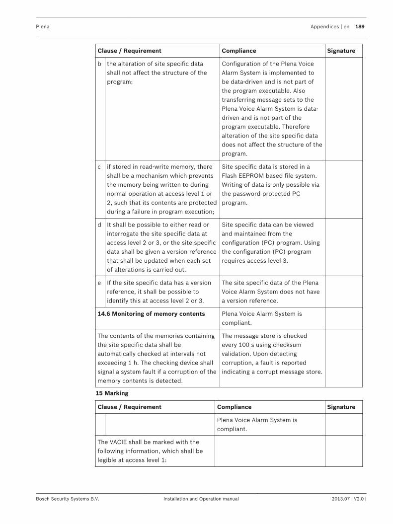
Clause / Requirement Compliance Signature
b the alteration of site specific datashall not affect the structure of theprogram;
Configuration of the Plena VoiceAlarm System is implemented tobe data-driven and is not part ofthe program executable. Alsotransferring message sets to thePlena Voice Alarm System is data-driven and is not part of theprogram executable. Thereforealteration of the site specific datadoes not affect the structure of theprogram.
c if stored in read-write memory, thereshall be a mechanism which preventsthe memory being written to duringnormal operation at access level 1 or2, such that its contents are protectedduring a failure in program execution;
Site specific data is stored in aFlash EEPROM based file system.Writing of data is only possible viathe password protected PCprogram.
d It shall be possible to either read orinterrogate the site specific data ataccess level 2 or 3, or the site specificdata shall be given a version referencethat shall be updated when each setof alterations is carried out.
Site specific data can be viewedand maintained from theconfiguration (PC) program. Usingthe configuration (PC) programrequires access level 3.
e If the site specific data has a versionreference, it shall be possible toidentify this at access level 2 or 3.
The site specific data of the PlenaVoice Alarm System does not havea version reference.
14.6 Monitoring of memory contents Plena Voice Alarm System iscompliant.
The contents of the memories containingthe site specific data shall beautomatically checked at intervals notexceeding 1 h. The checking device shallsignal a system fault if a corruption of thememory contents is detected.
The message store is checkedevery 100 s using checksumvalidation. Upon detectingcorruption, a fault is reportedindicating a corrupt message store.
15 Marking
Clause / Requirement Compliance Signature
Plena Voice Alarm System iscompliant.
The VACIE shall be marked with thefollowing information, which shall belegible at access level 1:
Plena Appendices | en 189
Bosch Security Systems B.V. Installation and Operation manual 2013.07 | V2.0 |
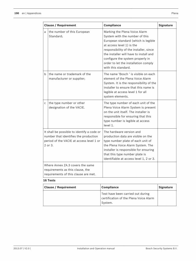
Clause / Requirement Compliance Signature
a the number of this EuropeanStandard;
Marking the Plena Voice AlarmSystem with the number of thisEuropean standard (which is legibleat access level 1) is theresponsibility of the installer, sincethe installer will have to install andconfigure the system properly inorder to let the installation complywith this standard.
b the name or trademark of themanufacturer or supplier;
The name ‘Bosch ’ is visible on eachelement of the Plena Voice AlarmSystem. It is the responsibility of theinstaller to ensure that this name islegible at access level 1 for allsystem elements.
c the type number or otherdesignation of the VACIE.
The type number of each unit of thePlena Voice Alarm System is presenton the unit itself. The installer isresponsible for ensuring that thistype number is legible at accesslevel 1.
It shall be possible to identify a code ornumber that identifies the productionperiod of the VACIE at access level 1 or2 or 3.
The hardware version andproduction data are visible on thetype number plate of each unit ofthe Plena Voice Alarm System. Theinstaller is responsible for ensuringthat this type number plate isidentifiable at access level 1, 2 or 3.
Where Annex ZA.3 covers the samerequirements as this clause, therequirements of this clause are met.
16 Tests
Clause / Requirement Compliance Signature
Test have been carried out duringcertification of the Plena Voice AlarmSystem.
190 en | Appendices Plena
2013.07 | V2.0 | Installation and Operation manual Bosch Security Systems B.V.

Bosch Security Systems B.V.
Torenallee 49
5617 BA Eindhoven
The Netherlands
www.boschsecurity.com
© Bosch Security Systems B.V., 2013
![winprotocoldoc.blob.core.windows.net · Web view[MS-RDPERP]: Remote Desktop Protocol: Remote Programs Virtual Channel Extension. Intellectual Property Rights Notice for Open Specifications](https://img.pdfslide.us/doc/110x75/608875057ace8720be5141c3/web-view-ms-rdperp-remote-desktop-protocol-remote-programs-virtual-channel-extension.jpg)


![[MS-RDPEV]: Remote Desktop Protocol: Video Redirection ......Remote Desktop Protocol: Video Redirection Virtual Channel Extension Intellectual Property Rights Notice for Open Specifications](https://img.pdfslide.us/doc/110x75/5f2c40542d26833bae366532/ms-rdpev-remote-desktop-protocol-video-redirection-remote-desktop-protocol.jpg)

![[MS-RDPEUDP]: Remote Desktop Protocol: UDP Transport Extension... · 6 / 46 [MS-RDPEUDP] — v20140502 Remote Desktop Protocol: UDP Transport Extension Copyright © 2014 Microsoft](https://img.pdfslide.us/doc/110x75/5f378e8fd45a1f0ba67b10f7/ms-rdpeudp-remote-desktop-protocol-udp-transport-extension-6-46-ms-rdpeudp.jpg)
![[MS-RDPEA]: Remote Desktop Protocol: Audio Output Virtual ......2 / 65 [MS-RDPEA] — v20140502 Remote Desktop Protocol: Audio Output Virtual Channel Extension Copyright © 2014 Microsoft](https://img.pdfslide.us/doc/110x75/6140d5e783382e045471b3ed/ms-rdpea-remote-desktop-protocol-audio-output-virtual-2-65-ms-rdpea.jpg)
![[MS-RDPEGFX]: Remote Desktop Protocol: Graphics Pipeline Extension - Microsoft... · 2018-09-11 · 5 / 144 [MS-RDPEGFX] - v20180912 Remote Desktop Protocol: Graphics Pipeline Extension](https://img.pdfslide.us/doc/110x75/5e8a8c64a687c1211e4cd620/ms-rdpegfx-remote-desktop-protocol-graphics-pipeline-extension-microsoft-.jpg)
![winprotocoldoc.blob.core.windows.net€¦ · Web view[MS-RDPELE]: Remote Desktop Protocol: Licensing Extension. Intellectual Property Rights Notice for Open Specifications Documentation](https://img.pdfslide.us/doc/110x75/5eae63941f5c7146d4233155/web-view-ms-rdpele-remote-desktop-protocol-licensing-extension-intellectual.jpg)
![[MS-RDPESP]: Remote Desktop Protocol: Serial and Parallel Port … · 2018. 9. 11. · Remote Desktop Protocol: Serial and Parallel Port Virtual Channel Extension Intellectual Property](https://img.pdfslide.us/doc/110x75/60a8c10cc48aed28813a4780/ms-rdpesp-remote-desktop-protocol-serial-and-parallel-port-2018-9-11-remote.jpg)
![[MS-RDPEVOR]: Remote Desktop Protocol: Video Optimized ...... · Release: September 12, 2018 1 Introduction The Remote Desktop Protocol: Video Optimized Remoting Virtual Channel Extension](https://img.pdfslide.us/doc/110x75/5f3652086a60c62ef366b34b/ms-rdpevor-remote-desktop-protocol-video-optimized-release-september.jpg)
![winprotocoldoc.blob.core.windows.net... · Web view[MS-RDPRFX]: Remote Desktop Protocol: RemoteFX Codec Extension. Intellectual Property Rights Notice for Open Specifications Documentation](https://img.pdfslide.us/doc/110x75/5addf3e67f8b9a4a268e3746/viewms-rdprfx-remote-desktop-protocol-remotefx-codec-extension-intellectual.jpg)

![winprotocoldoc.blob.core.windows.net › ... › [MS-RD… · Web view[MS-RDPEV]: Remote Desktop Protocol: Video Redirection Virtual Channel Extension. Intellectual Property Rights](https://img.pdfslide.us/doc/110x75/5f218b7e2f349c67b5170487/a-a-ms-rd-web-view-ms-rdpev-remote-desktop-protocol-video-redirection.jpg)


![[MS-RDPEFS]: Remote Desktop Protocol: File System Virtual …... · 2018. 9. 11. · Remote Desktop Protocol: File System Virtual Channel Extension Intellectual Property Rights Notice](https://img.pdfslide.us/doc/110x75/6073bc1d50e68d013f181fa9/ms-rdpefs-remote-desktop-protocol-file-system-virtual-2018-9-11-remote.jpg)

![[MS-RDPERP]: Remote Desktop Protocol: Remote Programs ...... · 2 / 97 [MS-RDPERP] - v20160714 Remote Desktop Protocol: Remote Programs Virtual Channel Extension Copyright © 2016](https://img.pdfslide.us/doc/110x75/6001d70f342c8842893c15ae/ms-rdperp-remote-desktop-protocol-remote-programs-2-97-ms-rdperp.jpg)

![[MS-RDPEUDP]: Remote Desktop Protocol: UDP Transport Extension... · 2019-09-23 · The Remote Desktop Protocol: UDP Transport Extension specifies extensions to the transport mechanisms](https://img.pdfslide.us/doc/110x75/5fae72aef586e668f97869ca/ms-rdpeudp-remote-desktop-protocol-udp-transport-extension-2019-09-23.jpg)

![winprotocoldoc.blob.core.windows.net... · Web view[MS-RDPEUDP]: Remote Desktop Protocol: UDP Transport Extension. Intellectual Property Rights Notice for Open Specifications Documentation](https://img.pdfslide.us/doc/110x75/5a7b0a637f8b9a2e6e8b981f/viewms-rdpeudp-remote-desktop-protocol-udp-transport-extension-intellectual.jpg)
![[MS-RDPEUDP]: Remote Desktop Protocol: UDP Transport Extension - Microsoft... · 2020-03-01 · Remote Desktop Protocol (RDP): A multi-channel protocol that allows a user to connect](https://img.pdfslide.us/doc/110x75/5e8583f4ed84a91c1b4314fd/ms-rdpeudp-remote-desktop-protocol-udp-transport-extension-microsoft-.jpg)