Embed Size (px)
Citation preview

1
LABORATORY OF THE STRUCTURAL DIVISION OF THE DEPART MENT OF CIVIL ENGINEERING OF MINHO UNIVERSITY
1 – INTRODUCTION
The Laboratory of the Structural Division of the Department of Civil Engineering of Minho University, with the designation of LEST, occupies three floors of approximately 200 m2 each one, totalizing a area of about 600 m2 (see Figure 1). These spaces are organized in test zones and areas for the preparation and post-inspection of the test specimens. The floor of PAV1 (Fig. 1a) is made by a heavily reinforced concrete slab of 450 mm thickness with a grid of holes of 90 mm diameter to clamp steel profiles and other devices, in order to serve as a reaction slab. Thick reinforced concrete walls at the contour of PAV1 give partial clamped support conditions to this RC slab, resulting a very stiff structure. PAV1 also includes a RC reaction wall, where specimens can be submitted to multiaxial load configurations. A room for the technical staff is also part of PAV1. PAV2 (Fig. 1b) is the basement of the laboratory and is dedicated, mainly, to the accommodation of materials and test specimens. Finally, PAV3 includes the most recent equipments and is planned to have an area where students can carry out tests within the ambit of the lessons. PAV3 also includes rooms for the technical staff, researchers and to accommodate equipment of high precision.
The laboratory is equipped with several servo-controlled equipments for tests that need to be executed under force or deflection control. A servo-controlled biaxial machine (2000 kN in compression and 200 kN in tension), a load frame for servo-controlled compression tests (2500 kN) and a modern fatigue machine (+/-1000 kN) are some of the equipment available on LEST. A climatic chamber, a furnace and a carbonation chamber are also part of the LEST equipment. A detailed description of the equipment available in LEST is given in Chapter 3. 2 – SPACES
Tables 1 to 3 describe the main areas composing the three floors of LEST. Photos of the equipment installed in these areas, and representative tests that can be executed are illustrated in Figure 2. Table 1
PAV1 Reference Description CD Zone of charge and discharge A1 Zone 1 to place specimens before and after have been tested A2 Zone 2 to place specimens before and after have been tested A3 Zone 3 to place specimens before and after have been tested E1.1 Test zone with a steel frame of 600 kN load capacity, to which a servo-actuator of 550 kN is
connected. This servo-actuator is commanded by SENTUR II E1.2 Teste zone for punching shear tests or for flexural tests with continuous beams/slabs (SENTUR II or
SENTUR III) E2.1 Test zone with a steel frame of 50 kN load capacity, to which a servo-actuator of 25 kN is
connected. This servo-actuator is commanded by SENTUR III E2.2 Test zone with a steel frame of 300 kN load capacity, to which servo-actuators can be connected.
These servo-actuator are commanded by SENTUR III E3 Test zone for biaxial tests using the reaction frame. The servo-actuators are commanded by
SENTUR IV. E4 Biaxial machine

2
Table 2 PAV2
Reference Description A4 Zone 4 to stock materials and objects that are necessary for the tests. A5 Zone 5 to stock materials and objects that are necessary for the tests. PP1 Zone for the preparation of specimens before testing program. E5 Teste zone for walls (SENTUR V) T1 Tanqs for ageing tests S Zone to stock aggregates Table 3
PAV3 Reference Description E7.1 Reaction Frame for fatige tests. E7.2 Reaction Frame for cyclic tests. E8 Load frame for compression tests (2500 kN in close-loop control; 5000 kN in
pressure control) E9 Fatigue frame of +/-1000 kN E10 Pull-out frame PL Pre-stress line. CC1 Climatic chamber 1. CC2 Climatic chamber 2. CC3 Climatic chamber 3. CC4 Climatic chamber 4. MF Furnace. CO Carbonation chamber T2/T3/T4 Tanqs for ageing tests A6 Zone 6 to place specimens before and after have been tested
a)

3
b)
b) Figure 1 – Floors of LEST Photos
E2.1
E1.1

4
E1.2
E2.2 E3
E3 E4

5
E8 E9
MF CC1
Figure 2 – Equipments and test setups.
6
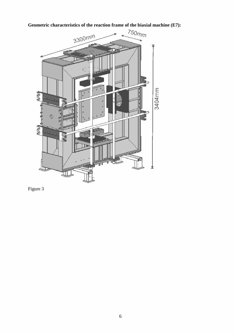
Geometric characteristics of the reaction frame of the biaxial machine (E7):
Figure 3

7
Loaded frame of E4:
Figure 4 3 – EQUIPMENTS Test equipments
Servo-controlled fatigue machine of +/- 1000 kN (frequency not exceeding 12 Hz); Servo-controlled system for static tests that can control one axis: SENTUR II; Servo-controlled systems for static tests that can control two axis: SENTUR III, SENTUR V; Servo-controlled systems for fatigue tests (frequency not exceeding 4 Hz): SENTUR IV; Biaxial machine of 2000kN in compression and 200 kN in tension; Equipment for compression tests (2500 kN in close-loop; 5000 kN in pressure control); Six devices for creep tests
Actuators (C – compression; T - Tension)
Servo-actuator of 100 kN (T/C) Non-servo-actuators: 2 of 50 kN and 4 of 100 kN; Servo-actuators: 1 of 600 kN (C); 1 of 200 kN (T/C) 1 of 300 kN (T/C); 200 kN (T/C); 1 of 100 kN (T/C); 2 of 50 kN(T/C);
Hydraulic groups
Hydraulic group to control non-servo-actuators
Displacement transducers

8
Type Reference Measuring length Linearity Connexion to SENTUR (channel) Model
DD1 (DC) 211.20-2001 "+/- 2,5 (mm) "+/- 0.05 % 7B HBM
Displacement.(AC) 2990 "+/- 12,5 (mm) "+/- 0.06% 3A RDP Displacement (AC) 2987 "+/- 12,5 (mm) "+/- 0.08% 3B RDP Displacement (AC) 3558 "+/- 25 (mm) "+/- 0.09 % 2A RDP Displacement (AC) 3468 "+/- 25 (mm) "+/- 0.08 % 4B RDP Displacement (AC) 2934 "+/- 12,5 (mm) "+/- 0.10 % 1A RDP Displacement (AC) 31923 "+/- 2,5 (mm) "+/- 0.16 % 8B RDP Displacement (AC) 39916 "+/- 2,5 (mm) "+/- 0.10 % 1B RDP Displacement (AC) 19948 "+/- 2,5 (mm) "+/- 0.09 % 2B RDP Displacement (AC) 47790 "+/- 2,5 (mm) "+/- 0.02 % 4A RDP
Displacement HBM(AC) 50710122 10 (mm) "+/- 0.05 % 8A HBM Displacement (DC) 13625 0_6.3 (mm) "+/- 0.05 % It is not connected MPE Displacement (AC) 18897 "+/- 50 (mm) "+/- 0.08 % It is not connected RDP Displacement (AC) 47789 "+/- 2,5 (mm) "+/- 0.06% Connected to the 2nd Computer RDP Displacement (AC) 40351 "+/- 5 (mm) "+/- 0.17% It is not connected RDP Displacement (AC) 40352 "+/- 5 (mm) "+/- 0.17% It is not connected RDP Displacement (AC) 31925 "+/- 2,5 (mm) "+/- 0.22% It is not connected RDP Displacement (AC) 19661 "+/- 12,5 (mm) "+/- 0.06% It is not connected RDP Displacement (AC) 19906 "+/- 25 (mm) "+/- 0.07% It is not connected RDP Displacement (AC) 50855 "+/- 2,5 (mm) "+/- 0.09% It is not connected RDP Displacement (AC) 50237 "+/- 1 (mm) "+/- 0.1% It is not connected RDP Displacement (AC) 50238 "+/- 1 (mm) "+/- 0.08% It is not connected RDP Displacement (AC) 50239 "+/- 1 (mm) "+/- 0.08% It is not connected RDP 8 Acelerómetros Pressure transducer
Model P3MB, Reference CP_HBM_1000 Model Pressure transmitter, Reference CP_CG_600 Load cells and force transducers
Type Reference Load capacity Linearity
Connexion to SENTUR (channel) Model
Force (DC) 1221EX 250 KN "+/- 0.05
% 5A INTERFACE
Force (DC) H30162 50 KN(2) "+/- 0.5
% 7A HBM
Force (DC) H30153 50 KN(1) "+/- 0.5
% 5B HBM
Force (DC) S91165 10 KN "+/- 0.05
% 6A HBM
Force (DC) 14285 200 KN "+/- 0.05
% Connected to SENTUR Microteste Force (DC) H? 20 KN "+/- 0.5% It is not connected HBM
Force (DC) 32200 100 KN "+/-
0.05% Connected to the second computer HBM Force (DC) 500 kN (T/C) Force (DC) 200 kN (T/C) Force (DC) 300 kN (T/C) Force (DC) 25 kN (T/C) Force (DC) 1000 kN (C) Force (DC) 25 kN (T/C) Force (DC) 25 kN (C)

9
Data acquisition systems
HBM, model MGCPlus, designation SA_HBM_MGCPlus; 4 Modelar 600 RDP; 2 Amplifiers for strain gages; 2 Spyder 8 A module of SCXI of National Instruments Reaction frames
50 steel profiles for reaction frames Reaction fram of the compression machine, reference PR_GC_700 Reaction frame of 1000 kN carrying capacity Computers
5 Computers Moulds
22 cylindrical moulds 150*30mm 9 prismatic moulds 150*150*600mm Miscellaneous
Aspirador Industrial 2 Porta paletes Ponte rolante 5000Kg Registógrafo Pilodyn 6J Câmara Buroscópica Mini OTDR Ramac / GPR DRMS 2 Aparelhos de Soldar 3 Rebarbadoras 3 Máquinas de Furar Multímetro Igómetro / Termómetro Aparelho de Ultra-sons Máquina de Etiquetagem Esclerómetro Detector de Armaduras 2 Alomgametros – 1 Digital / 1 Analógico Ups Pulse Analiser Martelo Instrumentado

![Repair and Partial Replacement of the Highway Department ... AND... · Gates, Landscaping. [Division 3]: ... Structural Steel, ... Architectural Woodwork, Plastic Fabrications. [Division](https://img.pdfslide.us/doc/110x75/5b0015ec7f8b9ad85d8c1bee/repair-and-partial-replacement-of-the-highway-department-andgates-landscaping.jpg)