Embed Size (px)
Citation preview
Configuration and Management of Networks - 2013
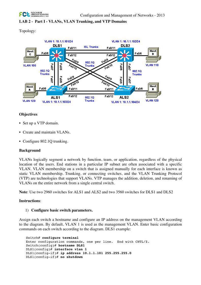
LAB 2 - Part I - VLANs, VLAN Trunking, and VTP Domains Topology:
Objectives
• Set up a VTP domain.
• Create and maintain VLANs.
• Configure 802.1Q trunking. ���
Background ���
VLANs logically segment a network by function, team, or application, regardless of the physical location of the users. End stations in a particular IP subnet are often associated with a specific VLAN. VLAN membership on a switch that is assigned manually for each interface is known as static VLAN membership. ���Trunking, or connecting switches, and the VLAN Trunking Protocol (VTP) are technologies that support VLANs. VTP manages the addition, deletion, and renaming of VLANs on the entire network from a single central switch.
Note: Use two 2960 switches for ALS1 and ALS2 and two 3560 switches for DLS1 and DLS2
Instructions:
1) Configure basic switch parameters. ���Assign each switch a hostname and configure an IP address on the management VLAN according to the diagram. By default, VLAN 1 is used as the management VLAN. ���Enter basic configuration commands on each switch according to the diagram. DLS1 example:
All contents are Copyright © 1992–2010 Cisco Systems, Inc. All rights reserved. This document is Cisco Public Information. Page 1 of 16
CCNPv6 SWITCH
Chapter 2 Lab 2-1, Static VLANS, VLAN Trunking, and VTP Domains and Modes
Topology
Objectives x Set up a VTP domain. x Create and maintain VLANs. x Configure ISL and 802.1Q trunking.
Background VLANs logically segment a network by function, team, or application, regardless of the physical location of the users. End stations in a particular IP subnet are often associated with a specific VLAN. VLAN membership on a switch that is assigned manually for each interface is known as static VLAN membership.
Trunking, or connecting switches, and the VLAN Trunking Protocol (VTP) are technologies that support VLANs. VTP manages the addition, deletion, and renaming of VLANs on the entire network from a single central switch.
Note: This lab uses Cisco WS-C2960-24TT-L switches with the Cisco IOS image c2960-lanbasek9-mz.122-46.SE.bin, and Catalyst 3560-24PS with the Cisco IOS image c3560-advipservicesk9-mz.122-46.SE.bin. You can use other switches (such as a 2950 or 3550) and Cisco IOS Software versions if they have comparable capabilities and features. Depending on the switch model and Cisco IOS Software version, the commands available and output produced might vary from what is shown in this lab.
CCNPv6 SWITCH
All contents are Copyright © 1992–2010 Cisco Systems, Inc. All rights reserved. This document is Cisco Public Information. Page 2 of 16
Required Resources x 2 switches (Cisco 2960 with the Cisco IOS Release 12.2(46)SE C2960-LANBASEK9-M image or
comparable) x 2 switches (Cisco 3560 with the Cisco IOS Release 12.2(46)SE C3560-ADVIPSERVICESK9-M
image or comparable) x 4 PCs (optional) x Ethernet and console cables
Step 1: Prepare the switches for the lab. Power up the switches and use the standard process for establishing a HyperTerminal console connection from a workstation to each switch in your pod. If you are connecting remotely to the switches, follow the instructions that have been supplied by your instructor.
Remove all VLAN information and configurations that may have been previously entered into the switches. Refer to Lab 1-1, “Clearing a Switch,” and Lab 1-2, “Clearing a Switch Connected to a Larger Network.”
Step 2: Configure basic switch parameters. Assign each switch a hostname and configure an IP address on the management VLAN according to the diagram. By default, VLAN 1 is used as the management VLAN.
Enter basic configuration commands on each switch according to the diagram.
DLS1 example: Switch# configure terminal Enter configuration commands, one per line. End with CNTL/Z. Switch(config)# hostname DLS1 DLS1(config)# interface vlan 1 DLS1(config-if)# ip address 10.1.1.101 255.255.255.0 DLS1(config-if)# no shutdown
(Optional) On each switch, create an enable secret password and configure the vty lines to allow remote access from other network devices.
DLS1 example: DLS1(config)# enable secret cisco DLS1(config)# line vty 0 15 DLS1(config-line)# password cisco DLS1(config-line)# login
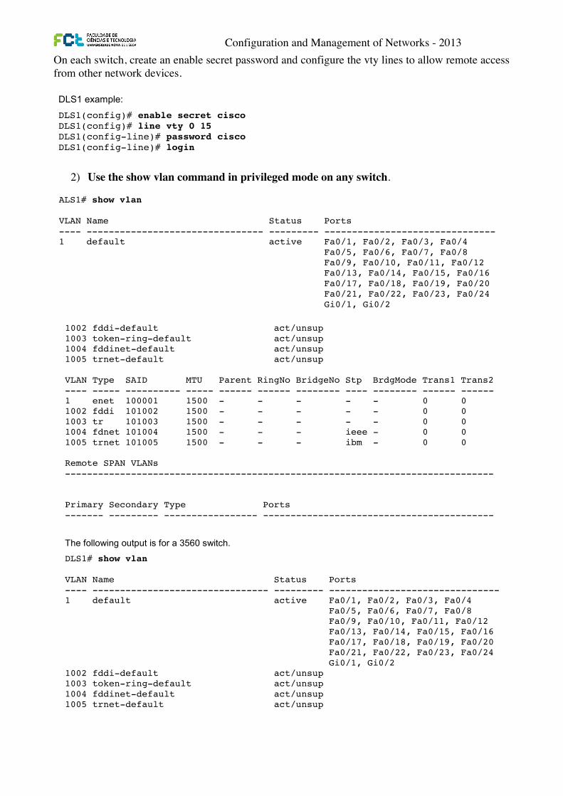
Step 3: Display the switch default VLAN information. Use the show vlan command in privileged mode on any switch. The following output is for a 2960 switch.
ALS1# show vlan VLAN Name Status Ports ---- -------------------------------- --------- ------------------------------- 1 default active Fa0/1, Fa0/2, Fa0/3, Fa0/4 Fa0/5, Fa0/6, Fa0/7, Fa0/8 Fa0/9, Fa0/10, Fa0/11, Fa0/12 Fa0/13, Fa0/14, Fa0/15, Fa0/16 Fa0/17, Fa0/18, Fa0/19, Fa0/20 Fa0/21, Fa0/22, Fa0/23, Fa0/24 Gi0/1, Gi0/2
Configuration and Management of Networks - 2013
On each switch, create an enable secret password and configure the vty lines to allow remote access from other network devices.
2) Use the show vlan command in privileged mode on any switch.
CCNPv6 SWITCH
All contents are Copyright © 1992–2010 Cisco Systems, Inc. All rights reserved. This document is Cisco Public Information. Page 2 of 16
Required Resources x 2 switches (Cisco 2960 with the Cisco IOS Release 12.2(46)SE C2960-LANBASEK9-M image or
comparable) x 2 switches (Cisco 3560 with the Cisco IOS Release 12.2(46)SE C3560-ADVIPSERVICESK9-M
image or comparable) x 4 PCs (optional) x Ethernet and console cables
Step 1: Prepare the switches for the lab. Power up the switches and use the standard process for establishing a HyperTerminal console connection from a workstation to each switch in your pod. If you are connecting remotely to the switches, follow the instructions that have been supplied by your instructor.
Remove all VLAN information and configurations that may have been previously entered into the switches. Refer to Lab 1-1, “Clearing a Switch,” and Lab 1-2, “Clearing a Switch Connected to a Larger Network.”
Step 2: Configure basic switch parameters. Assign each switch a hostname and configure an IP address on the management VLAN according to the diagram. By default, VLAN 1 is used as the management VLAN.
Enter basic configuration commands on each switch according to the diagram.
DLS1 example: Switch# configure terminal Enter configuration commands, one per line. End with CNTL/Z. Switch(config)# hostname DLS1 DLS1(config)# interface vlan 1 DLS1(config-if)# ip address 10.1.1.101 255.255.255.0 DLS1(config-if)# no shutdown
(Optional) On each switch, create an enable secret password and configure the vty lines to allow remote access from other network devices.
DLS1 example: DLS1(config)# enable secret cisco DLS1(config)# line vty 0 15 DLS1(config-line)# password cisco DLS1(config-line)# login
Step 3: Display the switch default VLAN information. Use the show vlan command in privileged mode on any switch. The following output is for a 2960 switch.
ALS1# show vlan VLAN Name Status Ports ---- -------------------------------- --------- ------------------------------- 1 default active Fa0/1, Fa0/2, Fa0/3, Fa0/4 Fa0/5, Fa0/6, Fa0/7, Fa0/8 Fa0/9, Fa0/10, Fa0/11, Fa0/12 Fa0/13, Fa0/14, Fa0/15, Fa0/16 Fa0/17, Fa0/18, Fa0/19, Fa0/20 Fa0/21, Fa0/22, Fa0/23, Fa0/24 Gi0/1, Gi0/2
CCNPv6 SWITCH
All contents are Copyright © 1992–2010 Cisco Systems, Inc. All rights reserved. This document is Cisco Public Information. Page 2 of 16
Required Resources x 2 switches (Cisco 2960 with the Cisco IOS Release 12.2(46)SE C2960-LANBASEK9-M image or
comparable) x 2 switches (Cisco 3560 with the Cisco IOS Release 12.2(46)SE C3560-ADVIPSERVICESK9-M
image or comparable) x 4 PCs (optional) x Ethernet and console cables
Step 1: Prepare the switches for the lab. Power up the switches and use the standard process for establishing a HyperTerminal console connection from a workstation to each switch in your pod. If you are connecting remotely to the switches, follow the instructions that have been supplied by your instructor.
Remove all VLAN information and configurations that may have been previously entered into the switches. Refer to Lab 1-1, “Clearing a Switch,” and Lab 1-2, “Clearing a Switch Connected to a Larger Network.”
Step 2: Configure basic switch parameters. Assign each switch a hostname and configure an IP address on the management VLAN according to the diagram. By default, VLAN 1 is used as the management VLAN.
Enter basic configuration commands on each switch according to the diagram.
DLS1 example: Switch# configure terminal Enter configuration commands, one per line. End with CNTL/Z. Switch(config)# hostname DLS1 DLS1(config)# interface vlan 1 DLS1(config-if)# ip address 10.1.1.101 255.255.255.0 DLS1(config-if)# no shutdown
(Optional) On each switch, create an enable secret password and configure the vty lines to allow remote access from other network devices.
DLS1 example: DLS1(config)# enable secret cisco DLS1(config)# line vty 0 15 DLS1(config-line)# password cisco DLS1(config-line)# login
Step 3: Display the switch default VLAN information. Use the show vlan command in privileged mode on any switch. The following output is for a 2960 switch.
ALS1# show vlan VLAN Name Status Ports ---- -------------------------------- --------- ------------------------------- 1 default active Fa0/1, Fa0/2, Fa0/3, Fa0/4 Fa0/5, Fa0/6, Fa0/7, Fa0/8 Fa0/9, Fa0/10, Fa0/11, Fa0/12 Fa0/13, Fa0/14, Fa0/15, Fa0/16 Fa0/17, Fa0/18, Fa0/19, Fa0/20 Fa0/21, Fa0/22, Fa0/23, Fa0/24 Gi0/1, Gi0/2 CCNPv6 SWITCH
All contents are Copyright © 1992–2010 Cisco Systems, Inc. All rights reserved. This document is Cisco Public Information. Page 3 of 16
1002 fddi-default act/unsup 1003 token-ring-default act/unsup 1004 fddinet-default act/unsup 1005 trnet-default act/unsup VLAN Type SAID MTU Parent RingNo BridgeNo Stp BrdgMode Trans1 Trans2 ---- ----- ---------- ----- ------ ------ -------- ---- -------- ------ ------ 1 enet 100001 1500 - - - - - 0 0 1002 fddi 101002 1500 - - - - - 0 0 1003 tr 101003 1500 - - - - - 0 0 1004 fdnet 101004 1500 - - - ieee - 0 0 1005 trnet 101005 1500 - - - ibm - 0 0 Remote SPAN VLANs ------------------------------------------------------------------------------ Primary Secondary Type Ports ------- --------- ----------------- ------------------------------------------
The following output is for a 3560 switch.
DLS1# show vlan VLAN Name Status Ports ---- -------------------------------- --------- ------------------------------- 1 default active Fa0/1, Fa0/2, Fa0/3, Fa0/4 Fa0/5, Fa0/6, Fa0/7, Fa0/8 Fa0/9, Fa0/10, Fa0/11, Fa0/12 Fa0/13, Fa0/14, Fa0/15, Fa0/16 Fa0/17, Fa0/18, Fa0/19, Fa0/20 Fa0/21, Fa0/22, Fa0/23, Fa0/24 Gi0/1, Gi0/2 1002 fddi-default act/unsup 1003 token-ring-default act/unsup 1004 fddinet-default act/unsup 1005 trnet-default act/unsup VLAN Type SAID MTU Parent RingNo BridgeNo Stp BrdgMode Trans1 Trans2 ---- ----- ---------- ----- ------ ------ -------- ---- -------- ------ ------ 1 enet 100001 1500 - - - - - 0 0 1002 fddi 101002 1500 - - - - - 0 0 1003 tr 101003 1500 - - - - - 0 0 1004 fdnet 101004 1500 - - - ieee - 0 0 1005 trnet 101005 1500 - - - ibm - 0 0 Remote SPAN VLANs ------------------------------------------------------------------------------ Primary Secondary Type Ports ------- --------- ----------------- ------------------------------------------
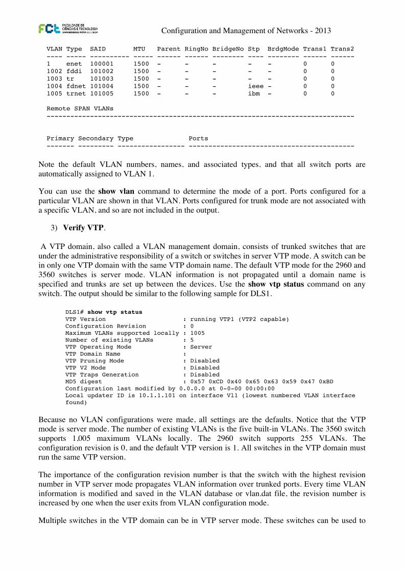
Note the default VLAN numbers, names, and associated types, and that all switch ports are automatically assigned to VLAN 1.
CCNPv6 SWITCH
All contents are Copyright © 1992–2010 Cisco Systems, Inc. All rights reserved. This document is Cisco Public Information. Page 3 of 16
1002 fddi-default act/unsup 1003 token-ring-default act/unsup 1004 fddinet-default act/unsup 1005 trnet-default act/unsup VLAN Type SAID MTU Parent RingNo BridgeNo Stp BrdgMode Trans1 Trans2 ---- ----- ---------- ----- ------ ------ -------- ---- -------- ------ ------ 1 enet 100001 1500 - - - - - 0 0 1002 fddi 101002 1500 - - - - - 0 0 1003 tr 101003 1500 - - - - - 0 0 1004 fdnet 101004 1500 - - - ieee - 0 0 1005 trnet 101005 1500 - - - ibm - 0 0 Remote SPAN VLANs ------------------------------------------------------------------------------ Primary Secondary Type Ports ------- --------- ----------------- ------------------------------------------
The following output is for a 3560 switch.
DLS1# show vlan VLAN Name Status Ports ---- -------------------------------- --------- ------------------------------- 1 default active Fa0/1, Fa0/2, Fa0/3, Fa0/4 Fa0/5, Fa0/6, Fa0/7, Fa0/8 Fa0/9, Fa0/10, Fa0/11, Fa0/12 Fa0/13, Fa0/14, Fa0/15, Fa0/16 Fa0/17, Fa0/18, Fa0/19, Fa0/20 Fa0/21, Fa0/22, Fa0/23, Fa0/24 Gi0/1, Gi0/2 1002 fddi-default act/unsup 1003 token-ring-default act/unsup 1004 fddinet-default act/unsup 1005 trnet-default act/unsup VLAN Type SAID MTU Parent RingNo BridgeNo Stp BrdgMode Trans1 Trans2 ---- ----- ---------- ----- ------ ------ -------- ---- -------- ------ ------ 1 enet 100001 1500 - - - - - 0 0 1002 fddi 101002 1500 - - - - - 0 0 1003 tr 101003 1500 - - - - - 0 0 1004 fdnet 101004 1500 - - - ieee - 0 0 1005 trnet 101005 1500 - - - ibm - 0 0 Remote SPAN VLANs ------------------------------------------------------------------------------ Primary Secondary Type Ports ------- --------- ----------------- ------------------------------------------
Note the default VLAN numbers, names, and associated types, and that all switch ports are automatically assigned to VLAN 1.
Configuration and Management of Networks - 2013
Note the default VLAN numbers, names, and associated types, and that all switch ports are automatically assigned to VLAN 1.
You can use the show vlan command to determine the mode of a port. Ports configured for a particular VLAN are shown in that VLAN. Ports configured for trunk mode are not associated with a specific VLAN, and so are not included in the output.
3) Verify VTP.
A VTP domain, also called a VLAN management domain, consists of trunked switches that are under the administrative responsibility of a switch or switches in server VTP mode. A switch can be in only one VTP domain with the same VTP domain name. The default VTP mode for the 2960 and 3560 switches is server mode. VLAN information is not propagated until a domain name is specified and trunks are set up between the devices. Use the show vtp status command on any switch. The output should be similar to the following sample for DLS1.
Because no VLAN configurations were made, all settings are the defaults. Notice that the VTP mode is server mode. The number of existing VLANs is the five built-in VLANs. The 3560 switch supports 1,005 maximum VLANs locally. The 2960 switch supports 255 VLANs. The configuration revision is 0, and the default VTP version is 1. All switches in the VTP domain must run the same VTP version.
The importance of the configuration revision number is that the switch with the highest revision number in VTP server mode propagates VLAN information over trunked ports. Every time VLAN information is modified and saved in the VLAN database or vlan.dat file, the revision number is increased by one when the user exits from VLAN configuration mode.
Multiple switches in the VTP domain can be in VTP server mode. These switches can be used to
CCNPv6 SWITCH
All contents are Copyright © 1992–2010 Cisco Systems, Inc. All rights reserved. This document is Cisco Public Information. Page 3 of 16
1002 fddi-default act/unsup 1003 token-ring-default act/unsup 1004 fddinet-default act/unsup 1005 trnet-default act/unsup VLAN Type SAID MTU Parent RingNo BridgeNo Stp BrdgMode Trans1 Trans2 ---- ----- ---------- ----- ------ ------ -------- ---- -------- ------ ------ 1 enet 100001 1500 - - - - - 0 0 1002 fddi 101002 1500 - - - - - 0 0 1003 tr 101003 1500 - - - - - 0 0 1004 fdnet 101004 1500 - - - ieee - 0 0 1005 trnet 101005 1500 - - - ibm - 0 0 Remote SPAN VLANs ------------------------------------------------------------------------------ Primary Secondary Type Ports ------- --------- ----------------- ------------------------------------------
The following output is for a 3560 switch.
DLS1# show vlan VLAN Name Status Ports ---- -------------------------------- --------- ------------------------------- 1 default active Fa0/1, Fa0/2, Fa0/3, Fa0/4 Fa0/5, Fa0/6, Fa0/7, Fa0/8 Fa0/9, Fa0/10, Fa0/11, Fa0/12 Fa0/13, Fa0/14, Fa0/15, Fa0/16 Fa0/17, Fa0/18, Fa0/19, Fa0/20 Fa0/21, Fa0/22, Fa0/23, Fa0/24 Gi0/1, Gi0/2 1002 fddi-default act/unsup 1003 token-ring-default act/unsup 1004 fddinet-default act/unsup 1005 trnet-default act/unsup VLAN Type SAID MTU Parent RingNo BridgeNo Stp BrdgMode Trans1 Trans2 ---- ----- ---------- ----- ------ ------ -------- ---- -------- ------ ------ 1 enet 100001 1500 - - - - - 0 0 1002 fddi 101002 1500 - - - - - 0 0 1003 tr 101003 1500 - - - - - 0 0 1004 fdnet 101004 1500 - - - ieee - 0 0 1005 trnet 101005 1500 - - - ibm - 0 0 Remote SPAN VLANs ------------------------------------------------------------------------------ Primary Secondary Type Ports ------- --------- ----------------- ------------------------------------------
Note the default VLAN numbers, names, and associated types, and that all switch ports are automatically assigned to VLAN 1.
CCNPv6 SWITCH
All contents are Copyright © 1992–2010 Cisco Systems, Inc. All rights reserved. This document is Cisco Public Information. Page 4 of 16
You can use the show vlan command to determine the mode of a port. Ports configured for a particular VLAN are shown in that VLAN. Ports configured for trunk mode are not associated with a specific VLAN, and so are not included in the output.
Step 4: Examine VTP information. A VTP domain, also called a VLAN management domain, consists of trunked switches that are under the administrative responsibility of a switch or switches in server VTP mode. A switch can be in only one VTP domain with the same VTP domain name. The default VTP mode for the 2960 and 3560 switches is server mode. VLAN information is not propagated until a domain name is specified and trunks are set up between the devices.
The following table describes the three VTP modes.
VTP Mode Description
VTP server You can create, modify, and delete VLANs and specify other configuration parameters, such as VTP version and VTP pruning, for the entire VTP domain. VTP servers advertise their VLAN configuration to other switches in the same VTP domain and synchronize their VLAN configuration with other switches based on advertisements received over trunk links.
VTP server is the default mode.
VTP client VTP clients behave the same way as VTP servers, but you cannot create, change, or delete VLANs on a VTP client.
VTP transparent VTP transparent switches do not participate in VTP. A VTP transparent switch does not advertise its VLAN configuration nor synchronize its VLAN configuration based on received advertisements. Transparent switches do forward VTP advertisements that they receive out their trunk ports in VTP Version 2.
Use the show vtp status command on any switch. The output should be similar to the following sample for DLS1.
DLS1# show vtp status VTP Version : running VTP1 (VTP2 capable) Configuration Revision : 0 Maximum VLANs supported locally : 1005 Number of existing VLANs : 5 VTP Operating Mode : Server VTP Domain Name : VTP Pruning Mode : Disabled VTP V2 Mode : Disabled VTP Traps Generation : Disabled MD5 digest : 0x57 0xCD 0x40 0x65 0x63 0x59 0x47 0xBD Configuration last modified by 0.0.0.0 at 0-0-00 00:00:00 Local updater ID is 10.1.1.101 on interface Vl1 (lowest numbered VLAN interface found)
Configuration and Management of Networks - 2013
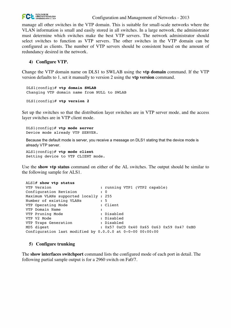
manage all other switches in the VTP domain. This is suitable for small-scale networks where the VLAN information is small and easily stored in all switches. In a large network, the administrator must determine which switches make the best VTP servers. The network administrator should select switches to function as VTP servers. The other switches in the VTP domain can be configured as clients. The number of VTP servers should be consistent based on the amount of redundancy desired in the network.
4) Configure VTP.
Change the VTP domain name on DLS1 to SWLAB using the vtp domain command. If the VTP version defaults to 1, set it manually to version 2 using the vtp version command.
Set up the switches so that the distribution layer switches are in VTP server mode, and the access layer switches are in VTP client mode.
Use the show vtp status command on either of the AL switches. The output should be similar to the following sample for ALS1.
5) Configure trunking
The show interfaces switchport command lists the configured mode of each port in detail. The following partial sample output is for a 2960 switch on Fa0/7.
CCNPv6 SWITCH
All contents are Copyright © 1992–2010 Cisco Systems, Inc. All rights reserved. This document is Cisco Public Information. Page 5 of 16
Because no VLAN configurations were made, all settings are the defaults. Notice that the VTP mode is server mode. The number of existing VLANs is the five built-in VLANs. The 3560 switch supports 1,005 maximum VLANs locally. The 2960 switch supports 255 VLANs. The configuration revision is 0, and the default VTP version is 1. All switches in the VTP domain must run the same VTP version.
The importance of the configuration revision number is that the switch with the highest revision number in VTP server mode propagates VLAN information over trunked ports. Every time VLAN information is modified and saved in the VLAN database or vlan.dat file, the revision number is increased by one when the user exits from VLAN configuration mode.
Multiple switches in the VTP domain can be in VTP server mode. These switches can be used to manage all other switches in the VTP domain. This is suitable for small-scale networks where the VLAN information is small and easily stored in all switches. In a large network, the administrator must determine which switches make the best VTP servers. The network administrator should select switches to function as VTP servers. The other switches in the VTP domain can be configured as clients. The number of VTP servers should be consistent based on the amount of redundancy desired in the network.
Step 5: Configure VTP on the switches. Change the VTP domain name on DLS1 to SWLAB using the vtp domain command. If the VTP version defaults to 1, set it manually to version 2 using the vtp version command.
DLS1(config)# vtp domain SWLAB Changing VTP domain name from NULL to SWLAB DLS1(config)# vtp version 2
Note: The newest VTP version, VTPv3, is not supported by the IOS used on the switches in this lab. However, it is supported in IOS versions 12.2(52)SE and newer on all platforms eligible for this IOS (2960, 3560, 3750, etc.). VTPv3 has improvements in three major areas.
Better administrative control over which device is allowed to update other devices’ view of the VLAN topology. The chance of unintended and disruptive changes is significantly reduced, and availability is increased.
Functionality for the VLAN environment has been significantly expanded. In addition to supporting the earlier ISL VLAN range from 1 to 1001, the new version supports the whole IEEE 802.1Q VLAN range up to 4095. In addition to supporting the concept of normal VLANs, VTP version 3 can transfer information regarding Private VLAN (PVLAN) structures.
The third area of major improvement is support for databases other than VLAN (for example, MST).
Set up the switches so that the distribution layer switches are in VTP server mode, and the access layer switches are in VTP client mode. Set the version number to 2 on the DL switches.
DLS1(config)# vtp mode server Device mode already VTP SERVER.
Because the default mode is server, you receive a message on DLS1 stating that the device mode is already VTP server. ALS1(config)# vtp mode client Setting device to VTP CLIENT mode.
Note: You cannot modify the version in VTP client mode
Use the show vtp status command on either of the AL switches. The output should be similar to the following sample for ALS1.
CCNPv6 SWITCH
All contents are Copyright © 1992–2010 Cisco Systems, Inc. All rights reserved. This document is Cisco Public Information. Page 6 of 16
ALS1# show vtp status VTP Version : running VTP1 (VTP2 capable) Configuration Revision : 0 Maximum VLANs supported locally : 255 Number of existing VLANs : 5 VTP Operating Mode : Client VTP Domain Name : VTP Pruning Mode : Disabled VTP V2 Mode : Disabled VTP Traps Generation : Disabled MD5 digest : 0x57 0xCD 0x40 0x65 0x63 0x59 0x47 0xBD Configuration last modified by 0.0.0.0 at 0-0-00 00:00:00
Notice that you do not see the VTP domain name that you set up on DLS1. Because no trunks are set up between the switches, they have not started to distribute any VLAN information. There is no IP address (0.0.0.0) or time listed for the last configuration modification.
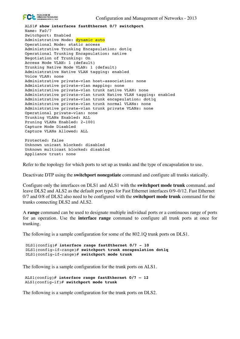
Step 6: Configure trunking. The show interfaces switchport command lists the configured mode of each port in detail. The following partial sample output is for a 2960 switch on Fa0/7.
ALS1# show interfaces fastEthernet 0/7 switchport Name: Fa0/7 Switchport: Enabled Administrative Mode: dynamic auto Operational Mode: static access Administrative Trunking Encapsulation: dot1q Operational Trunking Encapsulation: native Negotiation of Trunking: On Access Mode VLAN: 1 (default) Trunking Native Mode VLAN: 1 (default) Administrative Native VLAN tagging: enabled Voice VLAN: none Administrative private-vlan host-association: none Administrative private-vlan mapping: none Administrative private-vlan trunk native VLAN: none Administrative private-vlan trunk Native VLAN tagging: enabled Administrative private-vlan trunk encapsulation: dot1q Administrative private-vlan trunk normal VLANs: none Administrative private-vlan trunk private VLANs: none Operational private-vlan: none Trunking VLANs Enabled: ALL Pruning VLANs Enabled: 2-1001 Capture Mode Disabled Capture VLANs Allowed: ALL Protected: false Unknown unicast blocked: disabled Unknown multicast blocked: disabled Appliance trust: none
Ports on the 2960 and 3560 switches are set to dynamic auto by default. This means that they are willing to negotiate a trunk with the neighbor; however, if both sides are set to dynamic auto, the link will remain in access mode. This can be done by configuring one end of the trunk using the switchport mode trunk command. On the 3560 switches, you also need to configure the trunk encapsulation with the switchport
Configuration and Management of Networks - 2013
Refer to the topology for which ports to set up as trunks and the type of encapsulation to use.
Deactivate DTP using the switchport nonegotiate command and configure all trunks statically.
Configure only the interfaces on DLS1 and ALS1 with the switchport mode trunk command, and leave DLS2 and ALS2 as the default port types for Fast Ethernet interfaces 0/9–0/12. Fast Ethernet 0/7 and 0/8 of DLS2 also need to be configured with the switchport mode trunk command for the trunks connecting DLS2 and ALS2.
A range command can be used to designate multiple individual ports or a continuous range of ports for an operation. Use the interface range command to configure all trunk ports at once for trunking.
The following is a sample configuration for some of the 802.1Q trunk ports on DLS1.
The following is a sample configuration for the trunk ports on ALS1.
The following is a sample configuration for the trunk ports on DLS2.
CCNPv6 SWITCH
All contents are Copyright © 1992–2010 Cisco Systems, Inc. All rights reserved. This document is Cisco Public Information. Page 6 of 16
ALS1# show vtp status VTP Version : running VTP1 (VTP2 capable) Configuration Revision : 0 Maximum VLANs supported locally : 255 Number of existing VLANs : 5 VTP Operating Mode : Client VTP Domain Name : VTP Pruning Mode : Disabled VTP V2 Mode : Disabled VTP Traps Generation : Disabled MD5 digest : 0x57 0xCD 0x40 0x65 0x63 0x59 0x47 0xBD Configuration last modified by 0.0.0.0 at 0-0-00 00:00:00
Notice that you do not see the VTP domain name that you set up on DLS1. Because no trunks are set up between the switches, they have not started to distribute any VLAN information. There is no IP address (0.0.0.0) or time listed for the last configuration modification.
Step 6: Configure trunking. The show interfaces switchport command lists the configured mode of each port in detail. The following partial sample output is for a 2960 switch on Fa0/7.
ALS1# show interfaces fastEthernet 0/7 switchport Name: Fa0/7 Switchport: Enabled Administrative Mode: dynamic auto Operational Mode: static access Administrative Trunking Encapsulation: dot1q Operational Trunking Encapsulation: native Negotiation of Trunking: On Access Mode VLAN: 1 (default) Trunking Native Mode VLAN: 1 (default) Administrative Native VLAN tagging: enabled Voice VLAN: none Administrative private-vlan host-association: none Administrative private-vlan mapping: none Administrative private-vlan trunk native VLAN: none Administrative private-vlan trunk Native VLAN tagging: enabled Administrative private-vlan trunk encapsulation: dot1q Administrative private-vlan trunk normal VLANs: none Administrative private-vlan trunk private VLANs: none Operational private-vlan: none Trunking VLANs Enabled: ALL Pruning VLANs Enabled: 2-1001 Capture Mode Disabled Capture VLANs Allowed: ALL Protected: false Unknown unicast blocked: disabled Unknown multicast blocked: disabled Appliance trust: none
Ports on the 2960 and 3560 switches are set to dynamic auto by default. This means that they are willing to negotiate a trunk with the neighbor; however, if both sides are set to dynamic auto, the link will remain in access mode. This can be done by configuring one end of the trunk using the switchport mode trunk command. On the 3560 switches, you also need to configure the trunk encapsulation with the switchport
Configuration and Management of Networks - 2013
Refer to the topology for which ports to set up as trunks and the type of encapsulation to use.
Deactivate DTP using the switchport nonegotiate command and configure all trunks statically.
Configure only the interfaces on DLS1 and ALS1 with the switchport mode trunk command, and leave DLS2 and ALS2 as the default port types for Fast Ethernet interfaces 0/9–0/12. Fast Ethernet 0/7 and 0/8 of DLS2 also need to be configured with the switchport mode trunk command for the trunks connecting DLS2 and ALS2.
A range command can be used to designate multiple individual ports or a continuous range of ports for an operation. Use the interface range command to configure all trunk ports at once for trunking.
The following is a sample configuration for the 802.1Q and ISL trunk ports on DLS1.
The following is a sample configuration for the trunk ports on ALS1.
The following is a sample configuration for the trunk ports on DLS2.
CCNPv6 SWITCH
All contents are Copyright © 1992–2010 Cisco Systems, Inc. All rights reserved. This document is Cisco Public Information. Page 6 of 16
ALS1# show vtp status VTP Version : running VTP1 (VTP2 capable) Configuration Revision : 0 Maximum VLANs supported locally : 255 Number of existing VLANs : 5 VTP Operating Mode : Client VTP Domain Name : VTP Pruning Mode : Disabled VTP V2 Mode : Disabled VTP Traps Generation : Disabled MD5 digest : 0x57 0xCD 0x40 0x65 0x63 0x59 0x47 0xBD Configuration last modified by 0.0.0.0 at 0-0-00 00:00:00
Notice that you do not see the VTP domain name that you set up on DLS1. Because no trunks are set up between the switches, they have not started to distribute any VLAN information. There is no IP address (0.0.0.0) or time listed for the last configuration modification.
Step 6: Configure trunking. The show interfaces switchport command lists the configured mode of each port in detail. The following partial sample output is for a 2960 switch on Fa0/7.
ALS1# show interfaces fastEthernet 0/7 switchport Name: Fa0/7 Switchport: Enabled Administrative Mode: dynamic auto Operational Mode: static access Administrative Trunking Encapsulation: dot1q Operational Trunking Encapsulation: native Negotiation of Trunking: On Access Mode VLAN: 1 (default) Trunking Native Mode VLAN: 1 (default) Administrative Native VLAN tagging: enabled Voice VLAN: none Administrative private-vlan host-association: none Administrative private-vlan mapping: none Administrative private-vlan trunk native VLAN: none Administrative private-vlan trunk Native VLAN tagging: enabled Administrative private-vlan trunk encapsulation: dot1q Administrative private-vlan trunk normal VLANs: none Administrative private-vlan trunk private VLANs: none Operational private-vlan: none Trunking VLANs Enabled: ALL Pruning VLANs Enabled: 2-1001 Capture Mode Disabled Capture VLANs Allowed: ALL Protected: false Unknown unicast blocked: disabled Unknown multicast blocked: disabled Appliance trust: none
Ports on the 2960 and 3560 switches are set to dynamic auto by default. This means that they are willing to negotiate a trunk with the neighbor; however, if both sides are set to dynamic auto, the link will remain in access mode. This can be done by configuring one end of the trunk using the switchport mode trunk command. On the 3560 switches, you also need to configure the trunk encapsulation with the switchport
CCNPv6 SWITCH
All contents are Copyright © 1992–2010 Cisco Systems, Inc. All rights reserved. This document is Cisco Public Information. Page 7 of 16
trunk encapsulation command. The 3560 switch can use either Inter-Switch Link (ISL) or 802.1Q encapsulation, whereas the 2960 switch only supports 802.1Q.
Refer to the lab diagram for which ports to set up as trunks and the type of encapsulation to use.
Configure only the interfaces on DLS1 and ALS1 with the switchport mode trunk command, and leave DLS2 and ALS2 as the default port types for Fast Ethernet interfaces 0/9–0/12. Fast Ethernet 0/7 and 0/8 of DLS2 also need to be configured with the switchport mode trunk command for the trunks connecting DLS2 and ALS2.
The 2960 and 3560 switches have a range command that you can use to designate multiple individual ports or a continuous range of ports for an operation. Use the interface range command to configure all trunk ports at once for trunking.
The following is a sample configuration for the 802.1Q and ISL trunk ports on DLS1.
DLS1(config)# interface range fastEthernet 0/7 - 10 DLS1(config-if-range)# switchport trunk encapsulation dot1q DLS1(config-if-range)# switchport mode trunk DLS1(config)# interface range fastEthernet 0/11 - 12 DLS1(config-if-range)# switchport trunk encapsulation isl DLS1(config-if-range)# switchport mode trunk
The following is a sample configuration for the trunk ports on ALS1.
ALS1(config)# interface range fastEthernet 0/7 – 12 ALS1(config-if)# switchport mode trunk
The following is a sample configuration for the trunk ports on DLS2.
DLS2(config)# interface range fastEthernet 0/7 - 8 DLS2(config-if-range)# switchport trunk encapsulation dot1q DLS2(config-if-range)# switchport mode trunk
Note: This lab uses dynamic trunking protocol (DTP) to negotiate trunking, which can lead to security issues. In general, when configuring trunks, it is a good practice to deactivate DTP using the switchport nonegotiate command and configure all trunks statically.
Step 7: Verify trunk configuration. Use the show interfaces fastEthernet 0/7 switchport command on ALS2.
ALS2# show interfaces fastEthernet 0/7 switchport Name: Fa0/7 Switchport: Enabled Administrative Mode: dynamic auto Operational Mode: trunk Administrative Trunking Encapsulation: dot1q Operational Trunking Encapsulation: dot1q Negotiation of Trunking: On Access Mode VLAN: 1 (default) Trunking Native Mode VLAN: 1 (default) Administrative Native VLAN tagging: enabled Voice VLAN: none Administrative private-vlan host-association: none Administrative private-vlan mapping: none Administrative private-vlan trunk native VLAN: none
Configuration and Management of Networks - 2013
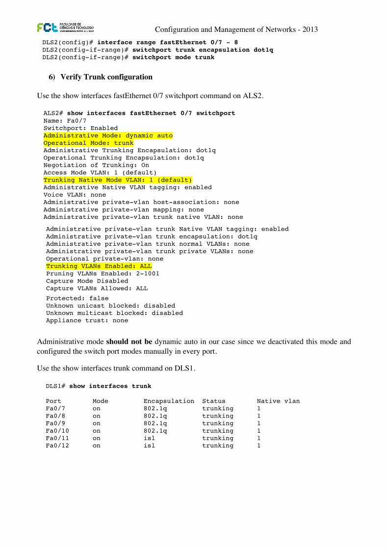
6) Verify Trunk configuration
Use the show interfaces fastEthernet 0/7 switchport command on ALS2.
Administrative mode should not be dynamic auto in our case since we deactivated this mode and configured the switch port modes manually in every port.
Use the show interfaces trunk command on DLS1.
CCNPv6 SWITCH
All contents are Copyright © 1992–2010 Cisco Systems, Inc. All rights reserved. This document is Cisco Public Information. Page 7 of 16
trunk encapsulation command. The 3560 switch can use either Inter-Switch Link (ISL) or 802.1Q encapsulation, whereas the 2960 switch only supports 802.1Q.
Refer to the lab diagram for which ports to set up as trunks and the type of encapsulation to use.
Configure only the interfaces on DLS1 and ALS1 with the switchport mode trunk command, and leave DLS2 and ALS2 as the default port types for Fast Ethernet interfaces 0/9–0/12. Fast Ethernet 0/7 and 0/8 of DLS2 also need to be configured with the switchport mode trunk command for the trunks connecting DLS2 and ALS2.
The 2960 and 3560 switches have a range command that you can use to designate multiple individual ports or a continuous range of ports for an operation. Use the interface range command to configure all trunk ports at once for trunking.
The following is a sample configuration for the 802.1Q and ISL trunk ports on DLS1.
DLS1(config)# interface range fastEthernet 0/7 - 10 DLS1(config-if-range)# switchport trunk encapsulation dot1q DLS1(config-if-range)# switchport mode trunk DLS1(config)# interface range fastEthernet 0/11 - 12 DLS1(config-if-range)# switchport trunk encapsulation isl DLS1(config-if-range)# switchport mode trunk
The following is a sample configuration for the trunk ports on ALS1.
ALS1(config)# interface range fastEthernet 0/7 – 12 ALS1(config-if)# switchport mode trunk
The following is a sample configuration for the trunk ports on DLS2.
DLS2(config)# interface range fastEthernet 0/7 - 8 DLS2(config-if-range)# switchport trunk encapsulation dot1q DLS2(config-if-range)# switchport mode trunk
Note: This lab uses dynamic trunking protocol (DTP) to negotiate trunking, which can lead to security issues. In general, when configuring trunks, it is a good practice to deactivate DTP using the switchport nonegotiate command and configure all trunks statically.
Step 7: Verify trunk configuration. Use the show interfaces fastEthernet 0/7 switchport command on ALS2.
ALS2# show interfaces fastEthernet 0/7 switchport Name: Fa0/7 Switchport: Enabled Administrative Mode: dynamic auto Operational Mode: trunk Administrative Trunking Encapsulation: dot1q Operational Trunking Encapsulation: dot1q Negotiation of Trunking: On Access Mode VLAN: 1 (default) Trunking Native Mode VLAN: 1 (default) Administrative Native VLAN tagging: enabled Voice VLAN: none Administrative private-vlan host-association: none Administrative private-vlan mapping: none Administrative private-vlan trunk native VLAN: none
CCNPv6 SWITCH
All contents are Copyright © 1992–2010 Cisco Systems, Inc. All rights reserved. This document is Cisco Public Information. Page 8 of 16
Administrative private-vlan trunk Native VLAN tagging: enabled Administrative private-vlan trunk encapsulation: dot1q Administrative private-vlan trunk normal VLANs: none Administrative private-vlan trunk private VLANs: none Operational private-vlan: none Trunking VLANs Enabled: ALL Pruning VLANs Enabled: 2-1001 Capture Mode Disabled Capture VLANs Allowed: ALL Protected: false Unknown unicast blocked: disabled Unknown multicast blocked: disabled Appliance trust: none
Notice that administrative mode on Fa0/7 is still the default dynamic auto. Fa0/7 on ALS2 is operating as a trunk, because port Fa0/7 of DLS2 was configured using the switchport mode trunk command. Once this command was issued, trunking was negotiated between the two switch ports.
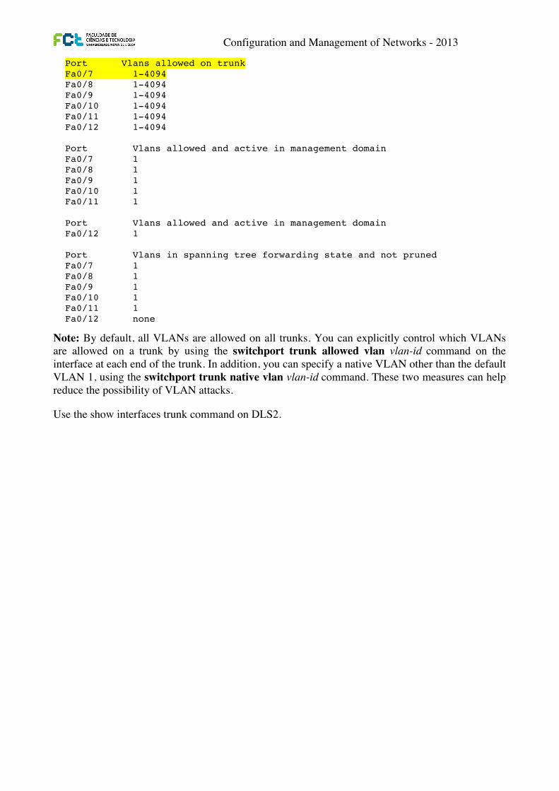
Use the show interfaces trunk command on DLS1. DLS1# show interfaces trunk Port Mode Encapsulation Status Native vlan Fa0/7 on 802.1q trunking 1 Fa0/8 on 802.1q trunking 1 Fa0/9 on 802.1q trunking 1 Fa0/10 on 802.1q trunking 1 Fa0/11 on isl trunking 1 Fa0/12 on isl trunking 1 Port Vlans allowed on trunk Fa0/7 1-4094 Fa0/8 1-4094 Fa0/9 1-4094 Fa0/10 1-4094 Fa0/11 1-4094 Fa0/12 1-4094 Port Vlans allowed and active in management domain Fa0/7 1 Fa0/8 1 Fa0/9 1 Fa0/10 1 Fa0/11 1 Port Vlans allowed and active in management domain Fa0/12 1 Port Vlans in spanning tree forwarding state and not pruned Fa0/7 1 Fa0/8 1 Fa0/9 1 Fa0/10 1 Fa0/11 1 Fa0/12 none
CCNPv6 SWITCH
All contents are Copyright © 1992–2010 Cisco Systems, Inc. All rights reserved. This document is Cisco Public Information. Page 8 of 16
Administrative private-vlan trunk Native VLAN tagging: enabled Administrative private-vlan trunk encapsulation: dot1q Administrative private-vlan trunk normal VLANs: none Administrative private-vlan trunk private VLANs: none Operational private-vlan: none Trunking VLANs Enabled: ALL Pruning VLANs Enabled: 2-1001 Capture Mode Disabled Capture VLANs Allowed: ALL Protected: false Unknown unicast blocked: disabled Unknown multicast blocked: disabled Appliance trust: none
Notice that administrative mode on Fa0/7 is still the default dynamic auto. Fa0/7 on ALS2 is operating as a trunk, because port Fa0/7 of DLS2 was configured using the switchport mode trunk command. Once this command was issued, trunking was negotiated between the two switch ports.
Use the show interfaces trunk command on DLS1. DLS1# show interfaces trunk Port Mode Encapsulation Status Native vlan Fa0/7 on 802.1q trunking 1 Fa0/8 on 802.1q trunking 1 Fa0/9 on 802.1q trunking 1 Fa0/10 on 802.1q trunking 1 Fa0/11 on isl trunking 1 Fa0/12 on isl trunking 1 Port Vlans allowed on trunk Fa0/7 1-4094 Fa0/8 1-4094 Fa0/9 1-4094 Fa0/10 1-4094 Fa0/11 1-4094 Fa0/12 1-4094 Port Vlans allowed and active in management domain Fa0/7 1 Fa0/8 1 Fa0/9 1 Fa0/10 1 Fa0/11 1 Port Vlans allowed and active in management domain Fa0/12 1 Port Vlans in spanning tree forwarding state and not pruned Fa0/7 1 Fa0/8 1 Fa0/9 1 Fa0/10 1 Fa0/11 1 Fa0/12 none
Configuration and Management of Networks - 2013
Note: By default, all VLANs are allowed on all trunks. You can explicitly control which VLANs are allowed on a trunk by using the switchport trunk allowed vlan vlan-id command on the interface at each end of the trunk. In addition, you can specify a native VLAN other than the default VLAN 1, using the switchport trunk native vlan vlan-id command. These two measures can help reduce the possibility of VLAN attacks.
Use the show interfaces trunk command on DLS2.
CCNPv6 SWITCH
All contents are Copyright © 1992–2010 Cisco Systems, Inc. All rights reserved. This document is Cisco Public Information. Page 8 of 16
Administrative private-vlan trunk Native VLAN tagging: enabled Administrative private-vlan trunk encapsulation: dot1q Administrative private-vlan trunk normal VLANs: none Administrative private-vlan trunk private VLANs: none Operational private-vlan: none Trunking VLANs Enabled: ALL Pruning VLANs Enabled: 2-1001 Capture Mode Disabled Capture VLANs Allowed: ALL Protected: false Unknown unicast blocked: disabled Unknown multicast blocked: disabled Appliance trust: none
Notice that administrative mode on Fa0/7 is still the default dynamic auto. Fa0/7 on ALS2 is operating as a trunk, because port Fa0/7 of DLS2 was configured using the switchport mode trunk command. Once this command was issued, trunking was negotiated between the two switch ports.
Use the show interfaces trunk command on DLS1. DLS1# show interfaces trunk Port Mode Encapsulation Status Native vlan Fa0/7 on 802.1q trunking 1 Fa0/8 on 802.1q trunking 1 Fa0/9 on 802.1q trunking 1 Fa0/10 on 802.1q trunking 1 Fa0/11 on isl trunking 1 Fa0/12 on isl trunking 1 Port Vlans allowed on trunk Fa0/7 1-4094 Fa0/8 1-4094 Fa0/9 1-4094 Fa0/10 1-4094 Fa0/11 1-4094 Fa0/12 1-4094 Port Vlans allowed and active in management domain Fa0/7 1 Fa0/8 1 Fa0/9 1 Fa0/10 1 Fa0/11 1 Port Vlans allowed and active in management domain Fa0/12 1 Port Vlans in spanning tree forwarding state and not pruned Fa0/7 1 Fa0/8 1 Fa0/9 1 Fa0/10 1 Fa0/11 1 Fa0/12 none
Configuration and Management of Networks - 2013
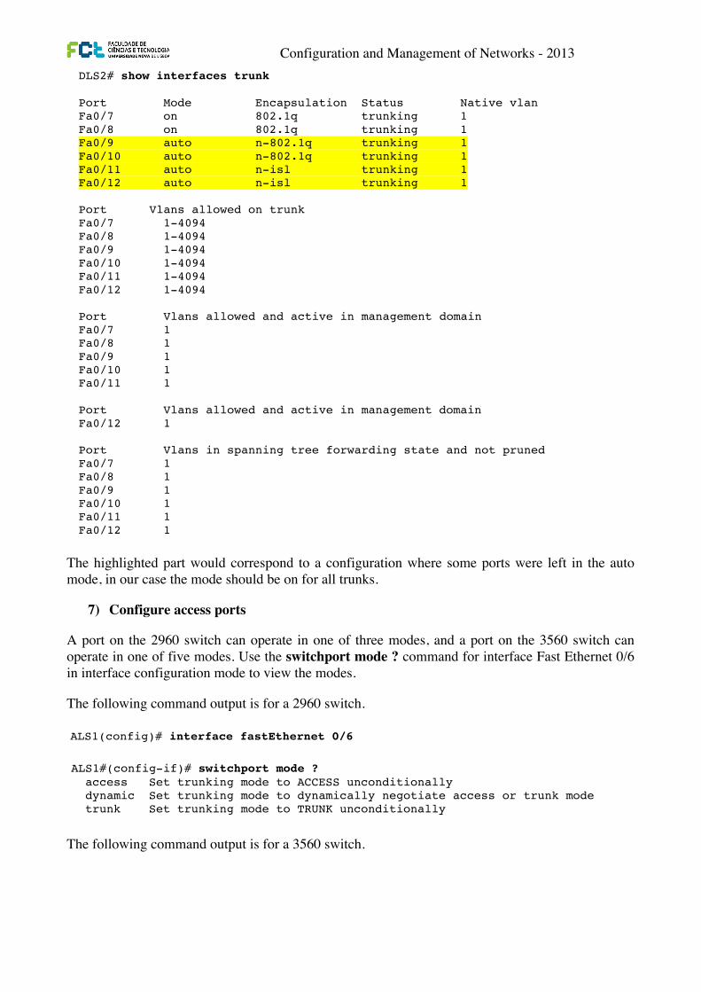
The highlighted part would correspond to a configuration where some ports were left in the auto mode, in our case the mode should be on for all trunks.
7) Configure access ports
A port on the 2960 switch can operate in one of three modes, and a port on the 3560 switch can operate in one of five modes. Use the switchport mode ? command for interface Fast Ethernet 0/6 in interface configuration mode to view the modes.
The following command output is for a 2960 switch.
The following command output is for a 3560 switch.
CCNPv6 SWITCH
All contents are Copyright © 1992–2010 Cisco Systems, Inc. All rights reserved. This document is Cisco Public Information. Page 9 of 16
Note: By default, all VLANs are allowed on all trunks. You can explicitly control which VLANs are allowed on a trunk by using the switchport trunk allowed vlan vlan-id command on the interface at each end of the trunk. In addition, you can specify a native VLAN other than the default VLAN 1, using the switchport trunk native vlan vlan-id command. These two measures can help reduce the possibility of VLAN attacks.
Use the show interfaces trunk command on DLS2.
DLS2# show interfaces trunk Port Mode Encapsulation Status Native vlan Fa0/7 on 802.1q trunking 1 Fa0/8 on 802.1q trunking 1 Fa0/9 auto n-802.1q trunking 1 Fa0/10 auto n-802.1q trunking 1 Fa0/11 auto n-isl trunking 1 Fa0/12 auto n-isl trunking 1 Port Vlans allowed on trunk Fa0/7 1-4094 Fa0/8 1-4094 Fa0/9 1-4094 Fa0/10 1-4094 Fa0/11 1-4094 Fa0/12 1-4094 Port Vlans allowed and active in management domain Fa0/7 1 Fa0/8 1 Fa0/9 1 Fa0/10 1 Fa0/11 1 Port Vlans allowed and active in management domain Fa0/12 1 Port Vlans in spanning tree forwarding state and not pruned Fa0/7 1 Fa0/8 1 Fa0/9 1 Fa0/10 1 Fa0/11 1 Fa0/12 1
Notice the highlighted portion of the above output from DLS2 where it indicates that these ports became trunks by negotiation. For example, port Fa0/9 mode is Auto and encapsulation is n-802.1q. The “n” indicates the 802.1q encapsulation was negotiated. The connected ports of the respective switches were configured using the switchport mode trunk command.
Step 8: Configure access ports. A port on the 2960 switch can operate in one of three modes, and a port on the 3560 switch can operate in one of five modes. Use the switchport mode ? command for interface Fast Ethernet 0/6 in interface configuration mode to view the modes.
The following command output is for a 2960 switch.
ALS1(config)# interface fastEthernet 0/6
CCNPv6 SWITCH
All contents are Copyright © 1992–2010 Cisco Systems, Inc. All rights reserved. This document is Cisco Public Information. Page 9 of 16
Note: By default, all VLANs are allowed on all trunks. You can explicitly control which VLANs are allowed on a trunk by using the switchport trunk allowed vlan vlan-id command on the interface at each end of the trunk. In addition, you can specify a native VLAN other than the default VLAN 1, using the switchport trunk native vlan vlan-id command. These two measures can help reduce the possibility of VLAN attacks.
Use the show interfaces trunk command on DLS2.
DLS2# show interfaces trunk Port Mode Encapsulation Status Native vlan Fa0/7 on 802.1q trunking 1 Fa0/8 on 802.1q trunking 1 Fa0/9 auto n-802.1q trunking 1 Fa0/10 auto n-802.1q trunking 1 Fa0/11 auto n-isl trunking 1 Fa0/12 auto n-isl trunking 1 Port Vlans allowed on trunk Fa0/7 1-4094 Fa0/8 1-4094 Fa0/9 1-4094 Fa0/10 1-4094 Fa0/11 1-4094 Fa0/12 1-4094 Port Vlans allowed and active in management domain Fa0/7 1 Fa0/8 1 Fa0/9 1 Fa0/10 1 Fa0/11 1 Port Vlans allowed and active in management domain Fa0/12 1 Port Vlans in spanning tree forwarding state and not pruned Fa0/7 1 Fa0/8 1 Fa0/9 1 Fa0/10 1 Fa0/11 1 Fa0/12 1
Notice the highlighted portion of the above output from DLS2 where it indicates that these ports became trunks by negotiation. For example, port Fa0/9 mode is Auto and encapsulation is n-802.1q. The “n” indicates the 802.1q encapsulation was negotiated. The connected ports of the respective switches were configured using the switchport mode trunk command.
Step 8: Configure access ports. A port on the 2960 switch can operate in one of three modes, and a port on the 3560 switch can operate in one of five modes. Use the switchport mode ? command for interface Fast Ethernet 0/6 in interface configuration mode to view the modes.
The following command output is for a 2960 switch.
ALS1(config)# interface fastEthernet 0/6 CCNPv6 SWITCH
All contents are Copyright © 1992–2010 Cisco Systems, Inc. All rights reserved. This document is Cisco Public Information. Page 10 of 16
ALS1#(config-if)# switchport mode ? access Set trunking mode to ACCESS unconditionally dynamic Set trunking mode to dynamically negotiate access or trunk mode trunk Set trunking mode to TRUNK unconditionally
The following command output is for a 3560 switch.
DLS1(config)# interface fastEthernet 0/6 DLS1(config-if)# switchport mode ? access Set trunking mode to ACCESS unconditionally dot1q-tunnel set trunking mode to TUNNEL unconditionally dynamic Set trunking mode to dynamically negotiate access or trunk mode private-vlan Set the mode to private-vlan host or promiscuous trunk Set trunking mode to TRUNK unconditionally
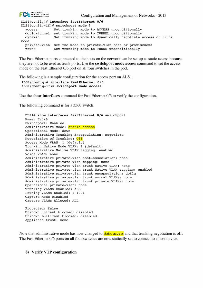
The Fast Ethernet ports connected to the hosts on the network can be set up as static access because they are not to be used as trunk ports. Use the switchport mode access command to set the access mode on the Fast Ethernet 0/6 port on all four switches in the pod.
The following is a sample configuration for the access port on ALS1.
ALS1(config)# interface fastEthernet 0/6 ALS1(config-if)# switchport mode access
Use the show interfaces command for Fast Ethernet 0/6 to verify the configuration.
The following command is for a 3560 switch.
DLS1# show interfaces fastEthernet 0/6 switchport Name: Fa0/6 Switchport: Enabled Administrative Mode: static access Operational Mode: down Administrative Trunking Encapsulation: negotiate Negotiation of Trunking: Off Access Mode VLAN: 1 (default) Trunking Native Mode VLAN: 1 (default) Administrative Native VLAN tagging: enabled Voice VLAN: none Administrative private-vlan host-association: none Administrative private-vlan mapping: none Administrative private-vlan trunk native VLAN: none Administrative private-vlan trunk Native VLAN tagging: enabled Administrative private-vlan trunk encapsulation: dot1q Administrative private-vlan trunk normal VLANs: none Administrative private-vlan trunk private VLANs: none Operational private-vlan: none Trunking VLANs Enabled: ALL Pruning VLANs Enabled: 2-1001 Capture Mode Disabled Capture VLANs Allowed: ALL Protected: false Unknown unicast blocked: disabled Unknown multicast blocked: disabled Appliance trust: none
Note that administrative mode has now changed to static access and that trunking negotiation is off. The Fast Ethernet 0/6 ports on all four switches are now statically set to connect to a host device.
Configuration and Management of Networks - 2013
The Fast Ethernet ports connected to the hosts on the network can be set up as static access because they are not to be used as trunk ports. Use the switchport mode access command to set the access mode on the Fast Ethernet 0/6 port on all four switches in the pod.
The following is a sample configuration for the access port on ALS1.
Use the show interfaces command for Fast Ethernet 0/6 to verify the configuration. The following command is for a 3560 switch.
Note that administrative mode has now changed to static access and that trunking negotiation is off. The Fast Ethernet 0/6 ports on all four switches are now statically set to connect to a host device.
8) Verify VTP configuration
CCNPv6 SWITCH
All contents are Copyright © 1992–2010 Cisco Systems, Inc. All rights reserved. This document is Cisco Public Information. Page 10 of 16
ALS1#(config-if)# switchport mode ? access Set trunking mode to ACCESS unconditionally dynamic Set trunking mode to dynamically negotiate access or trunk mode trunk Set trunking mode to TRUNK unconditionally
The following command output is for a 3560 switch.
DLS1(config)# interface fastEthernet 0/6 DLS1(config-if)# switchport mode ? access Set trunking mode to ACCESS unconditionally dot1q-tunnel set trunking mode to TUNNEL unconditionally dynamic Set trunking mode to dynamically negotiate access or trunk mode private-vlan Set the mode to private-vlan host or promiscuous trunk Set trunking mode to TRUNK unconditionally
The Fast Ethernet ports connected to the hosts on the network can be set up as static access because they are not to be used as trunk ports. Use the switchport mode access command to set the access mode on the Fast Ethernet 0/6 port on all four switches in the pod.
The following is a sample configuration for the access port on ALS1.
ALS1(config)# interface fastEthernet 0/6 ALS1(config-if)# switchport mode access
Use the show interfaces command for Fast Ethernet 0/6 to verify the configuration.
The following command is for a 3560 switch.
DLS1# show interfaces fastEthernet 0/6 switchport Name: Fa0/6 Switchport: Enabled Administrative Mode: static access Operational Mode: down Administrative Trunking Encapsulation: negotiate Negotiation of Trunking: Off Access Mode VLAN: 1 (default) Trunking Native Mode VLAN: 1 (default) Administrative Native VLAN tagging: enabled Voice VLAN: none Administrative private-vlan host-association: none Administrative private-vlan mapping: none Administrative private-vlan trunk native VLAN: none Administrative private-vlan trunk Native VLAN tagging: enabled Administrative private-vlan trunk encapsulation: dot1q Administrative private-vlan trunk normal VLANs: none Administrative private-vlan trunk private VLANs: none Operational private-vlan: none Trunking VLANs Enabled: ALL Pruning VLANs Enabled: 2-1001 Capture Mode Disabled Capture VLANs Allowed: ALL Protected: false Unknown unicast blocked: disabled Unknown multicast blocked: disabled Appliance trust: none
Note that administrative mode has now changed to static access and that trunking negotiation is off. The Fast Ethernet 0/6 ports on all four switches are now statically set to connect to a host device.
Configuration and Management of Networks - 2013
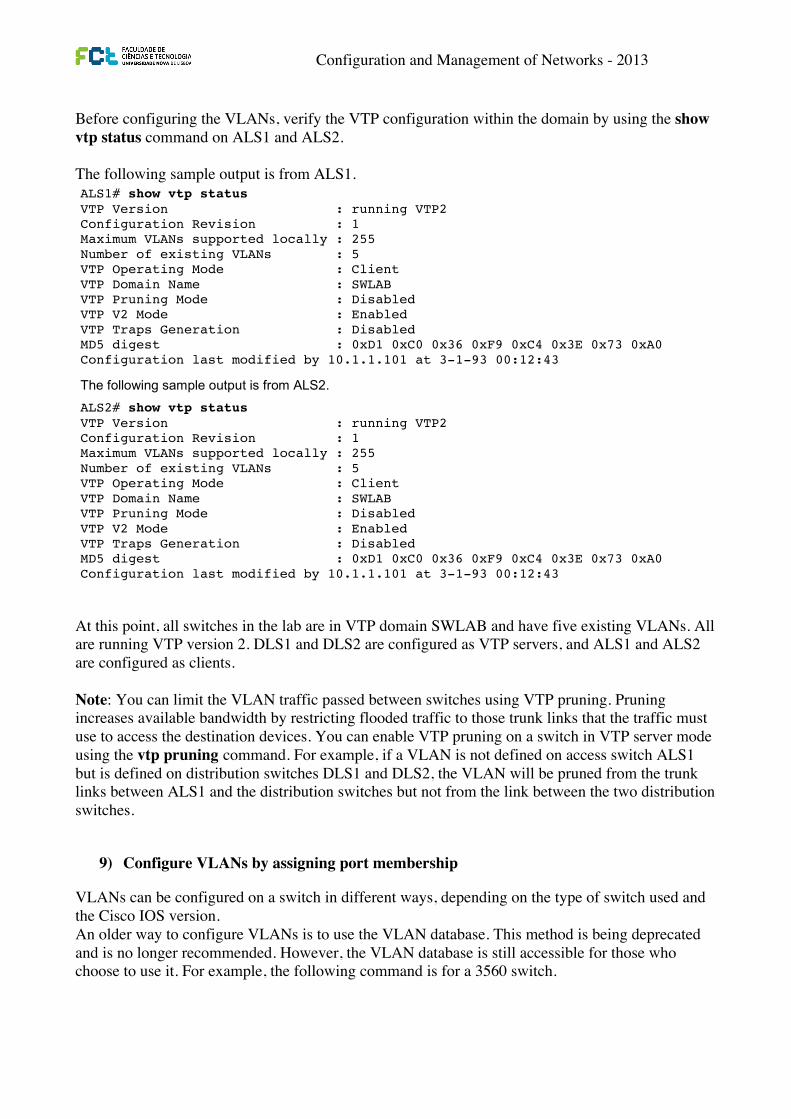
Before configuring the VLANs, verify the VTP configuration within the domain by using the show vtp status command on ALS1 and ALS2.��� The following sample output is from ALS1.
At this point, all switches in the lab are in VTP domain SWLAB and have five existing VLANs. All are running VTP version 2. DLS1 and DLS2 are configured as VTP servers, and ALS1 and ALS2 are configured as clients. Note: You can limit the VLAN traffic passed between switches using VTP pruning. Pruning increases available bandwidth by restricting flooded traffic to those trunk links that the traffic must use to access the destination devices. You can enable VTP pruning on a switch in VTP server mode using the vtp pruning command. For example, if a VLAN is not defined on access switch ALS1 but is defined on distribution switches DLS1 and DLS2, the VLAN will be pruned from the trunk links between ALS1 and the distribution switches but not from the link between the two distribution switches.
9) Configure VLANs by assigning port membership
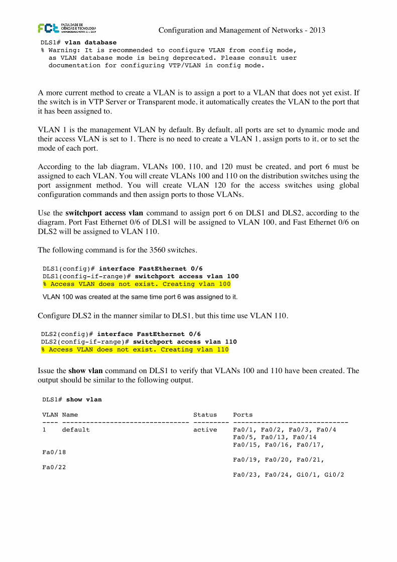
VLANs can be configured on a switch in different ways, depending on the type of switch used and the Cisco IOS version. An older way to configure VLANs is to use the VLAN database. This method is being deprecated and is no longer recommended. However, the VLAN database is still accessible for those who choose to use it. For example, the following command is for a 3560 switch.
CCNPv6 SWITCH
All contents are Copyright © 1992–2010 Cisco Systems, Inc. All rights reserved. This document is Cisco Public Information. Page 11 of 16
Step 9: Verify VTP configuration. Before configuring the VLANs, verify the VTP configuration within the domain by using the show vtp status command on ALS1 and ALS2.
The following sample output is from ALS1. ALS1# show vtp status VTP Version : running VTP2 Configuration Revision : 1 Maximum VLANs supported locally : 255 Number of existing VLANs : 5 VTP Operating Mode : Client VTP Domain Name : SWLAB VTP Pruning Mode : Disabled VTP V2 Mode : Enabled VTP Traps Generation : Disabled MD5 digest : 0xD1 0xC0 0x36 0xF9 0xC4 0x3E 0x73 0xA0 Configuration last modified by 10.1.1.101 at 3-1-93 00:12:43
The following sample output is from ALS2. ALS2# show vtp status VTP Version : running VTP2 Configuration Revision : 1 Maximum VLANs supported locally : 255 Number of existing VLANs : 5 VTP Operating Mode : Client VTP Domain Name : SWLAB VTP Pruning Mode : Disabled VTP V2 Mode : Enabled VTP Traps Generation : Disabled MD5 digest : 0xD1 0xC0 0x36 0xF9 0xC4 0x3E 0x73 0xA0 Configuration last modified by 10.1.1.101 at 3-1-93 00:12:43
At this point, all switches in the lab are in VTP domain SWLAB and have five existing VLANs. All are running VTP version 2. DLS1 and DLS2 are configured as VTP servers, and ALS1 and ALS2 are configured as clients.
Note: You can limit the VLAN traffic passed between switches using VTP pruning. Pruning increases available bandwidth by restricting flooded traffic to those trunk links that the traffic must use to access the destination devices. You can enable VTP pruning on a switch in VTP server mode using the vtp pruning command. For example, if a VLAN is not defined on access switch ALS1 but is defined on distribution switches DLS1 and DLS2, the VLAN will be pruned from the trunk links between ALS1 and the distribution switches but not from the link between the two distribution switches.
Step 10: Configure VLANs by assigning port membership. VLANs can be configured on a switch in different ways, depending on the type of switch used and the Cisco IOS version.
An older way to configure VLANs is to use the VLAN database. This method is being deprecated and is no longer recommended. However, the VLAN database is still accessible for those who choose to use it. For example, the following command is for a 3560 switch. DLS1# vlan database % Warning: It is recommended to configure VLAN from config mode, as VLAN database mode is being deprecated. Please consult user documentation for configuring VTP/VLAN in config mode.
Configuration and Management of Networks - 2013
A more current method to create a VLAN is to assign a port to a VLAN that does not yet exist. If the switch is in VTP Server or Transparent mode, it automatically creates the VLAN to the port that it has been assigned to. VLAN 1 is the management VLAN by default. By default, all ports are set to dynamic mode and their access VLAN is set to 1. There is no need to create a VLAN 1, assign ports to it, or to set the mode of each port. According to the lab diagram, VLANs 100, 110, and 120 must be created, and port 6 must be assigned to each VLAN. You will create VLANs 100 and 110 on the distribution switches using the port assignment method. You will create VLAN 120 for the access switches using global configuration commands and then assign ports to those VLANs. Use the switchport access vlan command to assign port 6 on DLS1 and DLS2, according to the diagram. Port Fast Ethernet 0/6 of DLS1 will be assigned to VLAN 100, and Fast Ethernet 0/6 on DLS2 will be assigned to VLAN 110. The following command is for the 3560 switches.
Configure DLS2 in the manner similar to DLS1, but this time use VLAN 110.
Issue the show vlan command on DLS1 to verify that VLANs 100 and 110 have been created. The output should be similar to the following output.
CCNPv6 SWITCH
All contents are Copyright © 1992–2010 Cisco Systems, Inc. All rights reserved. This document is Cisco Public Information. Page 11 of 16
Step 9: Verify VTP configuration. Before configuring the VLANs, verify the VTP configuration within the domain by using the show vtp status command on ALS1 and ALS2.
The following sample output is from ALS1. ALS1# show vtp status VTP Version : running VTP2 Configuration Revision : 1 Maximum VLANs supported locally : 255 Number of existing VLANs : 5 VTP Operating Mode : Client VTP Domain Name : SWLAB VTP Pruning Mode : Disabled VTP V2 Mode : Enabled VTP Traps Generation : Disabled MD5 digest : 0xD1 0xC0 0x36 0xF9 0xC4 0x3E 0x73 0xA0 Configuration last modified by 10.1.1.101 at 3-1-93 00:12:43
The following sample output is from ALS2. ALS2# show vtp status VTP Version : running VTP2 Configuration Revision : 1 Maximum VLANs supported locally : 255 Number of existing VLANs : 5 VTP Operating Mode : Client VTP Domain Name : SWLAB VTP Pruning Mode : Disabled VTP V2 Mode : Enabled VTP Traps Generation : Disabled MD5 digest : 0xD1 0xC0 0x36 0xF9 0xC4 0x3E 0x73 0xA0 Configuration last modified by 10.1.1.101 at 3-1-93 00:12:43
At this point, all switches in the lab are in VTP domain SWLAB and have five existing VLANs. All are running VTP version 2. DLS1 and DLS2 are configured as VTP servers, and ALS1 and ALS2 are configured as clients.
Note: You can limit the VLAN traffic passed between switches using VTP pruning. Pruning increases available bandwidth by restricting flooded traffic to those trunk links that the traffic must use to access the destination devices. You can enable VTP pruning on a switch in VTP server mode using the vtp pruning command. For example, if a VLAN is not defined on access switch ALS1 but is defined on distribution switches DLS1 and DLS2, the VLAN will be pruned from the trunk links between ALS1 and the distribution switches but not from the link between the two distribution switches.
Step 10: Configure VLANs by assigning port membership. VLANs can be configured on a switch in different ways, depending on the type of switch used and the Cisco IOS version.
An older way to configure VLANs is to use the VLAN database. This method is being deprecated and is no longer recommended. However, the VLAN database is still accessible for those who choose to use it. For example, the following command is for a 3560 switch. DLS1# vlan database % Warning: It is recommended to configure VLAN from config mode, as VLAN database mode is being deprecated. Please consult user documentation for configuring VTP/VLAN in config mode.
CCNPv6 SWITCH
All contents are Copyright © 1992–2010 Cisco Systems, Inc. All rights reserved. This document is Cisco Public Information. Page 12 of 16
A more current method to create a VLAN is to assign a port to a VLAN that does not yet exist. If the switch is in VTP Server or Transparent mode, it automatically creates the VLAN to the port that it has been assigned to.
VLAN 1 is the management VLAN by default. By default, all ports are set to dynamic mode and their access VLAN is set to 1. There is no need to create a VLAN 1, assign ports to it, or to set the mode of each port.
According to the lab diagram, VLANs 100, 110, and 120 must be created, and port 6 must be assigned to each VLAN. You will create VLANs 100 and 110 on the distribution switches using the port assignment method. You will create VLAN 120 for the access switches using global configuration commands and then assign ports to those VLANs.
Use the switchport access vlan command to assign port 6 on DLS1 and DLS2, according to the diagram. Port Fast Ethernet 0/6 of DLS1 will be assigned to VLAN 100, and Fast Ethernet 0/6 on DLS2 will be assigned to VLAN 110.
The following command is for the 3560 switches.
DLS1(config)# interface FastEthernet 0/6 DLS1(config-if-range)# switchport access vlan 100 % Access VLAN does not exist. Creating vlan 100
VLAN 100 was created at the same time port 6 was assigned to it.
Configure DLS2 in the manner similar to DLS1, but this time use VLAN 110.
DLS2(config)# interface FastEthernet 0/6 DLS2(config-if-range)# switchport access vlan 110 % Access VLAN does not exist. Creating vlan 110
Issue the show vlan command on DLS1 to verify that VLANs 100 and 110 have been created. The output should be similar to the following output.
DLS1# show vlan VLAN Name Status Ports ---- -------------------------------- --------- ----------------------------- 1 default active Fa0/1, Fa0/2, Fa0/3, Fa0/4 Fa0/5, Fa0/13, Fa0/14 Fa0/15, Fa0/16, Fa0/17, Fa0/18 Fa0/19, Fa0/20, Fa0/21, Fa0/22 Fa0/23, Fa0/24, Gi0/1, Gi0/2 100 VLAN0100 active Fa0/6 110 VLAN0110 active 1002 fddi-default act/unsup 1003 token-ring-default act/unsup 1004 fddinet-default act/unsup 1005 trnet-default act/unsup VLAN Type SAID MTU Parent RingNo BridgeNo Stp BrdgMode Trans1 Trans2 ---- ----- ---------- ----- ------ ------ -------- ---- -------- ------ ----- 1 enet 100001 1500 - - - - - 0 0 100 enet 100100 1500 - - - - - 0 0 110 enet 100110 1500 - - - - - 0 0 1002 fddi 101002 1500 - - - - - 0 0
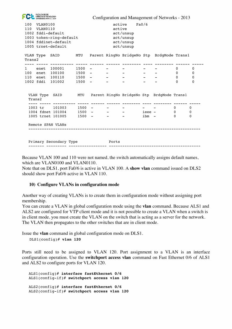
Configuration and Management of Networks - 2013
Because VLAN 100 and 110 were not named, the switch automatically assigns default names, which are VLAN0100 and VLAN0110. Note that on DLS1, port Fa0/6 is active in VLAN 100. A show vlan command issued on DLS2 should show port Fa0/6 active in VLAN 110.
10) Configure VLANs in configuration mode Another way of creating VLANs is to create them in configuration mode without assigning port membership. You can create a VLAN in global configuration mode using the vlan command. Because ALS1 and ALS2 are configured for VTP client mode and it is not possible to create a VLAN when a switch is in client mode, you must create the VLAN on the switch that is acting as a server for the network. The VLAN then propagates to the other switches that are in client mode. Issue the vlan command in global configuration mode on DLS1.
Ports still need to be assigned to VLAN 120. Port assignment to a VLAN is an interface configuration operation. Use the switchport access vlan command on Fast Ethernet 0/6 of ALS1 and ALS2 to configure ports for VLAN 120.
CCNPv6 SWITCH
All contents are Copyright © 1992–2010 Cisco Systems, Inc. All rights reserved. This document is Cisco Public Information. Page 12 of 16
A more current method to create a VLAN is to assign a port to a VLAN that does not yet exist. If the switch is in VTP Server or Transparent mode, it automatically creates the VLAN to the port that it has been assigned to.
VLAN 1 is the management VLAN by default. By default, all ports are set to dynamic mode and their access VLAN is set to 1. There is no need to create a VLAN 1, assign ports to it, or to set the mode of each port.
According to the lab diagram, VLANs 100, 110, and 120 must be created, and port 6 must be assigned to each VLAN. You will create VLANs 100 and 110 on the distribution switches using the port assignment method. You will create VLAN 120 for the access switches using global configuration commands and then assign ports to those VLANs.
Use the switchport access vlan command to assign port 6 on DLS1 and DLS2, according to the diagram. Port Fast Ethernet 0/6 of DLS1 will be assigned to VLAN 100, and Fast Ethernet 0/6 on DLS2 will be assigned to VLAN 110.
The following command is for the 3560 switches.
DLS1(config)# interface FastEthernet 0/6 DLS1(config-if-range)# switchport access vlan 100 % Access VLAN does not exist. Creating vlan 100
VLAN 100 was created at the same time port 6 was assigned to it.
Configure DLS2 in the manner similar to DLS1, but this time use VLAN 110.
DLS2(config)# interface FastEthernet 0/6 DLS2(config-if-range)# switchport access vlan 110 % Access VLAN does not exist. Creating vlan 110
Issue the show vlan command on DLS1 to verify that VLANs 100 and 110 have been created. The output should be similar to the following output.
DLS1# show vlan VLAN Name Status Ports ---- -------------------------------- --------- ----------------------------- 1 default active Fa0/1, Fa0/2, Fa0/3, Fa0/4 Fa0/5, Fa0/13, Fa0/14 Fa0/15, Fa0/16, Fa0/17, Fa0/18 Fa0/19, Fa0/20, Fa0/21, Fa0/22 Fa0/23, Fa0/24, Gi0/1, Gi0/2 100 VLAN0100 active Fa0/6 110 VLAN0110 active 1002 fddi-default act/unsup 1003 token-ring-default act/unsup 1004 fddinet-default act/unsup 1005 trnet-default act/unsup VLAN Type SAID MTU Parent RingNo BridgeNo Stp BrdgMode Trans1 Trans2 ---- ----- ---------- ----- ------ ------ -------- ---- -------- ------ ----- 1 enet 100001 1500 - - - - - 0 0 100 enet 100100 1500 - - - - - 0 0 110 enet 100110 1500 - - - - - 0 0 1002 fddi 101002 1500 - - - - - 0 0 CCNPv6 SWITCH
All contents are Copyright © 1992–2010 Cisco Systems, Inc. All rights reserved. This document is Cisco Public Information. Page 13 of 16
VLAN Type SAID MTU Parent RingNo BridgeNo Stp BrdgMode Trans1 Trans2 ---- ----- ---------- ----- ------ ------ -------- ---- -------- ------ ----- 1003 tr 101003 1500 - - - - - 0 0 1004 fdnet 101004 1500 - - - ieee - 0 0 1005 trnet 101005 1500 - - - ibm - 0 0 Remote SPAN VLANs ----------------------------------------------------------------------------- Primary Secondary Type Ports ------- --------- ----------------- -----------------------------------------
Because VLAN 100 and 110 were not named, the switch automatically assigns default names, which are VLAN0100 and VLAN0110.
Note that on DLS1, port Fa0/6 is active in VLAN 100. A show vlan command issued on DLS2 should show port Fa0/6 active in VLAN 110.
Step 11: Configure VLANs in configuration mode. Another way of creating VLANs is to create them in configuration mode without assigning port membership.
You can create a VLAN in global configuration mode using the vlan command. Because ALS1 and ALS2 are configured for VTP client mode and it is not possible to create a VLAN when a switch is in client mode, you must create the VLAN on the switch that is acting as a server for the network. The VLAN then propagates to the other switches that are in client mode.
Issue the vlan command in global configuration mode on DLS1.
DLS1(config)# vlan 120
Ports still need to be assigned to VLAN 120. Port assignment to a VLAN is an interface configuration operation. Use the switchport access vlan command on Fast Ethernet 0/6 of ALS1 and ALS2 to configure ports for VLAN 120.
ALS1(config)# interface fastEthernet 0/6 ALS1(config-if)# switchport access vlan 120 ALS2(config)# interface fastEthernet 0/6 ALS2(config-if)# switchport access vlan 120
Use the show vlan command to verify the creation of VLAN 120, with port Fa0/6 assigned to it. The output should be similar to the following.
ALS1# show vlan VLAN Name Status Ports ---- ------------------------------ --------- ----------------------------- 1 default active Fa0/1, Fa0/2, Fa0/3, Fa0/4 Fa0/5, Fa0/13, Fa0/14, Fa0/15 Fa0/16, Fa0/17, Fa0/18, Fa0/19 Fa0/20, Fa0/21, Fa0/22, Fa0/23 Fa0/24, Gi0/1, Gi0/2 100 VLAN0100 active 110 VLAN0110 active 120 VLAN0120 active Fa0/6 1002 fddi-default act/unsup 1003 token-ring-default act/unsup
CCNPv6 SWITCH
All contents are Copyright © 1992–2010 Cisco Systems, Inc. All rights reserved. This document is Cisco Public Information. Page 13 of 16
VLAN Type SAID MTU Parent RingNo BridgeNo Stp BrdgMode Trans1 Trans2 ---- ----- ---------- ----- ------ ------ -------- ---- -------- ------ ----- 1003 tr 101003 1500 - - - - - 0 0 1004 fdnet 101004 1500 - - - ieee - 0 0 1005 trnet 101005 1500 - - - ibm - 0 0 Remote SPAN VLANs ----------------------------------------------------------------------------- Primary Secondary Type Ports ------- --------- ----------------- -----------------------------------------
Because VLAN 100 and 110 were not named, the switch automatically assigns default names, which are VLAN0100 and VLAN0110.
Note that on DLS1, port Fa0/6 is active in VLAN 100. A show vlan command issued on DLS2 should show port Fa0/6 active in VLAN 110.
Step 11: Configure VLANs in configuration mode. Another way of creating VLANs is to create them in configuration mode without assigning port membership.
You can create a VLAN in global configuration mode using the vlan command. Because ALS1 and ALS2 are configured for VTP client mode and it is not possible to create a VLAN when a switch is in client mode, you must create the VLAN on the switch that is acting as a server for the network. The VLAN then propagates to the other switches that are in client mode.
Issue the vlan command in global configuration mode on DLS1.
DLS1(config)# vlan 120
Ports still need to be assigned to VLAN 120. Port assignment to a VLAN is an interface configuration operation. Use the switchport access vlan command on Fast Ethernet 0/6 of ALS1 and ALS2 to configure ports for VLAN 120.
ALS1(config)# interface fastEthernet 0/6 ALS1(config-if)# switchport access vlan 120 ALS2(config)# interface fastEthernet 0/6 ALS2(config-if)# switchport access vlan 120
Use the show vlan command to verify the creation of VLAN 120, with port Fa0/6 assigned to it. The output should be similar to the following.
ALS1# show vlan VLAN Name Status Ports ---- ------------------------------ --------- ----------------------------- 1 default active Fa0/1, Fa0/2, Fa0/3, Fa0/4 Fa0/5, Fa0/13, Fa0/14, Fa0/15 Fa0/16, Fa0/17, Fa0/18, Fa0/19 Fa0/20, Fa0/21, Fa0/22, Fa0/23 Fa0/24, Gi0/1, Gi0/2 100 VLAN0100 active 110 VLAN0110 active 120 VLAN0120 active Fa0/6 1002 fddi-default act/unsup 1003 token-ring-default act/unsup
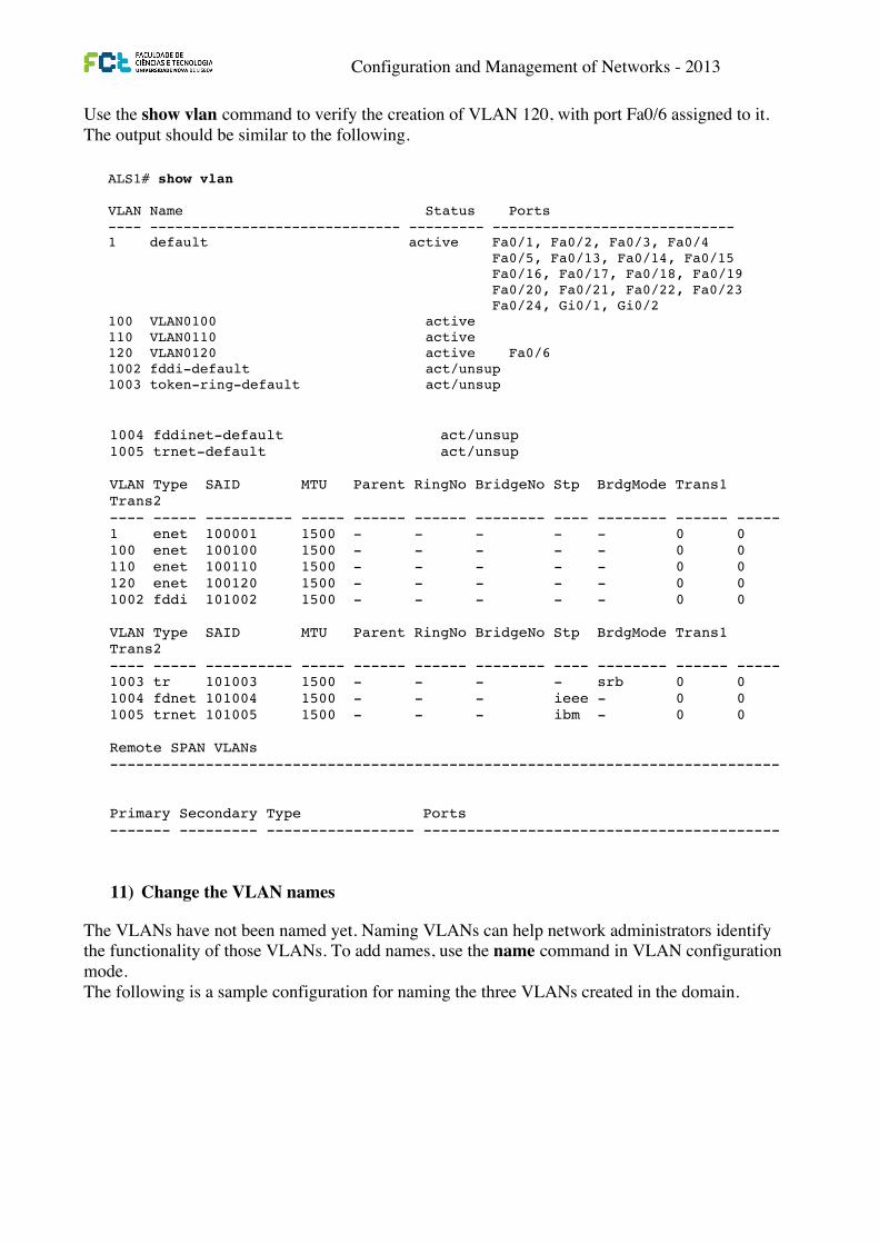
Configuration and Management of Networks - 2013
Use the show vlan command to verify the creation of VLAN 120, with port Fa0/6 assigned to it. The output should be similar to the following.
11) Change the VLAN names
The VLANs have not been named yet. Naming VLANs can help network administrators identify the functionality of those VLANs. To add names, use the name command in VLAN configuration mode. The following is a sample configuration for naming the three VLANs created in the domain.
CCNPv6 SWITCH
All contents are Copyright © 1992–2010 Cisco Systems, Inc. All rights reserved. This document is Cisco Public Information. Page 13 of 16
VLAN Type SAID MTU Parent RingNo BridgeNo Stp BrdgMode Trans1 Trans2 ---- ----- ---------- ----- ------ ------ -------- ---- -------- ------ ----- 1003 tr 101003 1500 - - - - - 0 0 1004 fdnet 101004 1500 - - - ieee - 0 0 1005 trnet 101005 1500 - - - ibm - 0 0 Remote SPAN VLANs ----------------------------------------------------------------------------- Primary Secondary Type Ports ------- --------- ----------------- -----------------------------------------
Because VLAN 100 and 110 were not named, the switch automatically assigns default names, which are VLAN0100 and VLAN0110.
Note that on DLS1, port Fa0/6 is active in VLAN 100. A show vlan command issued on DLS2 should show port Fa0/6 active in VLAN 110.
Step 11: Configure VLANs in configuration mode. Another way of creating VLANs is to create them in configuration mode without assigning port membership.
You can create a VLAN in global configuration mode using the vlan command. Because ALS1 and ALS2 are configured for VTP client mode and it is not possible to create a VLAN when a switch is in client mode, you must create the VLAN on the switch that is acting as a server for the network. The VLAN then propagates to the other switches that are in client mode.
Issue the vlan command in global configuration mode on DLS1.
DLS1(config)# vlan 120
Ports still need to be assigned to VLAN 120. Port assignment to a VLAN is an interface configuration operation. Use the switchport access vlan command on Fast Ethernet 0/6 of ALS1 and ALS2 to configure ports for VLAN 120.
ALS1(config)# interface fastEthernet 0/6 ALS1(config-if)# switchport access vlan 120 ALS2(config)# interface fastEthernet 0/6 ALS2(config-if)# switchport access vlan 120
Use the show vlan command to verify the creation of VLAN 120, with port Fa0/6 assigned to it. The output should be similar to the following.
ALS1# show vlan VLAN Name Status Ports ---- ------------------------------ --------- ----------------------------- 1 default active Fa0/1, Fa0/2, Fa0/3, Fa0/4 Fa0/5, Fa0/13, Fa0/14, Fa0/15 Fa0/16, Fa0/17, Fa0/18, Fa0/19 Fa0/20, Fa0/21, Fa0/22, Fa0/23 Fa0/24, Gi0/1, Gi0/2 100 VLAN0100 active 110 VLAN0110 active 120 VLAN0120 active Fa0/6 1002 fddi-default act/unsup 1003 token-ring-default act/unsup CCNPv6 SWITCH
All contents are Copyright © 1992–2010 Cisco Systems, Inc. All rights reserved. This document is Cisco Public Information. Page 14 of 16
1004 fddinet-default act/unsup 1005 trnet-default act/unsup VLAN Type SAID MTU Parent RingNo BridgeNo Stp BrdgMode Trans1 Trans2 ---- ----- ---------- ----- ------ ------ -------- ---- -------- ------ ----- 1 enet 100001 1500 - - - - - 0 0 100 enet 100100 1500 - - - - - 0 0 110 enet 100110 1500 - - - - - 0 0 120 enet 100120 1500 - - - - - 0 0 1002 fddi 101002 1500 - - - - - 0 0 VLAN Type SAID MTU Parent RingNo BridgeNo Stp BrdgMode Trans1 Trans2 ---- ----- ---------- ----- ------ ------ -------- ---- -------- ------ ----- 1003 tr 101003 1500 - - - - srb 0 0 1004 fdnet 101004 1500 - - - ieee - 0 0 1005 trnet 101005 1500 - - - ibm - 0 0 Remote SPAN VLANs ----------------------------------------------------------------------------- Primary Secondary Type Ports ------- --------- ----------------- -----------------------------------------
Step 12: Change the VLAN names. The VLANs have not been named yet. Naming VLANs can help network administrators identify the functionality of those VLANs. To add names, use the name command in VLAN configuration mode.
The following is a sample configuration for naming the three VLANs created in the domain.
DLS1(config)# vlan 100 DLS1(config-vlan)# name Server-Farm-1 DLS1(config-vlan)# exit DLS1(config)# vlan 110 DLS1(config-vlan)# name Server-Farm-2 DLS1(config-vlan)# exit DLS1(config)# vlan 120 DLS1(config-vlan)# name Net-Eng DLS1(config-vlan)# exit
Use the show vlan command on DLS1 to verify that the new names have been added.
DLS1# show vlan VLAN Name Status Ports ---- -------------------------------- --------- ------------------------------- 1 default active Fa0/1, Fa0/2, Fa0/3, Fa0/4 Fa0/5, Fa0/7, Fa0/8, Fa0/9 Fa0/10, Fa0/11, Fa0/12, Fa0/13 Fa0/14, Fa0/15, Fa0/16, Fa0/17 Fa0/18, Fa0/19, Fa0/20, Fa0/21 Fa0/22, Fa0/23, Fa0/24, Gi0/1 Gi0/2 100 Server-Farm-1 active Fa0/6 110 Server-Farm-2 active 120 Net-Eng active
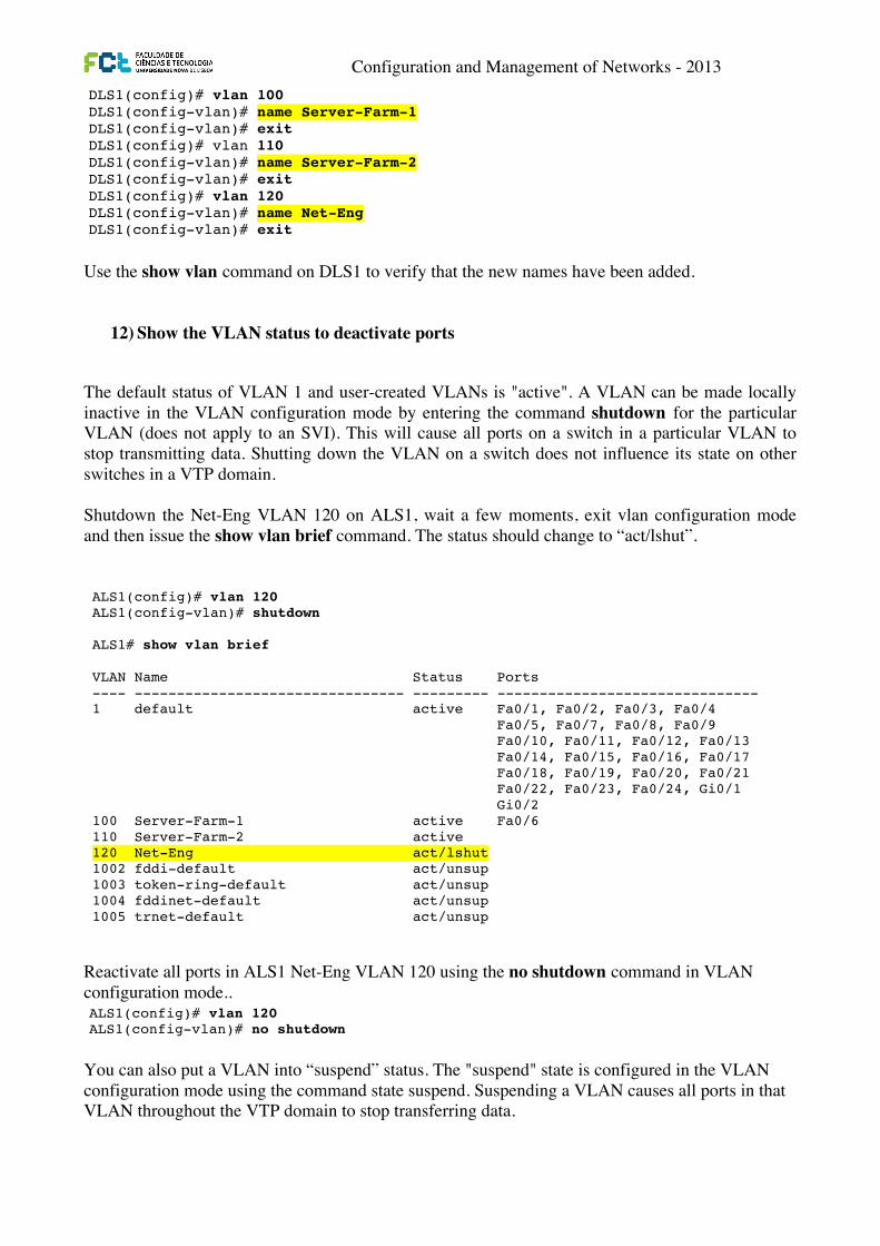
Configuration and Management of Networks - 2013
Use the show vlan command on DLS1 to verify that the new names have been added.
12) Show the VLAN status to deactivate ports
The default status of VLAN 1 and user-created VLANs is "active". A VLAN can be made locally inactive in the VLAN configuration mode by entering the command shutdown for the particular VLAN (does not apply to an SVI). This will cause all ports on a switch in a particular VLAN to stop transmitting data. Shutting down the VLAN on a switch does not influence its state on other switches in a VTP domain. Shutdown the Net-Eng VLAN 120 on ALS1, wait a few moments, exit vlan configuration mode and then issue the show vlan brief command. The status should change to “act/lshut”.
Reactivate all ports in ALS1 Net-Eng VLAN 120 using the no shutdown command in VLAN configuration mode..
You can also put a VLAN into “suspend” status. The "suspend" state is configured in the VLAN configuration mode using the command state suspend. Suspending a VLAN causes all ports in that VLAN throughout the VTP domain to stop transferring data.
CCNPv6 SWITCH
All contents are Copyright © 1992–2010 Cisco Systems, Inc. All rights reserved. This document is Cisco Public Information. Page 14 of 16
1004 fddinet-default act/unsup 1005 trnet-default act/unsup VLAN Type SAID MTU Parent RingNo BridgeNo Stp BrdgMode Trans1 Trans2 ---- ----- ---------- ----- ------ ------ -------- ---- -------- ------ ----- 1 enet 100001 1500 - - - - - 0 0 100 enet 100100 1500 - - - - - 0 0 110 enet 100110 1500 - - - - - 0 0 120 enet 100120 1500 - - - - - 0 0 1002 fddi 101002 1500 - - - - - 0 0 VLAN Type SAID MTU Parent RingNo BridgeNo Stp BrdgMode Trans1 Trans2 ---- ----- ---------- ----- ------ ------ -------- ---- -------- ------ ----- 1003 tr 101003 1500 - - - - srb 0 0 1004 fdnet 101004 1500 - - - ieee - 0 0 1005 trnet 101005 1500 - - - ibm - 0 0 Remote SPAN VLANs ----------------------------------------------------------------------------- Primary Secondary Type Ports ------- --------- ----------------- -----------------------------------------
Step 12: Change the VLAN names. The VLANs have not been named yet. Naming VLANs can help network administrators identify the functionality of those VLANs. To add names, use the name command in VLAN configuration mode.
The following is a sample configuration for naming the three VLANs created in the domain.
DLS1(config)# vlan 100 DLS1(config-vlan)# name Server-Farm-1 DLS1(config-vlan)# exit DLS1(config)# vlan 110 DLS1(config-vlan)# name Server-Farm-2 DLS1(config-vlan)# exit DLS1(config)# vlan 120 DLS1(config-vlan)# name Net-Eng DLS1(config-vlan)# exit
Use the show vlan command on DLS1 to verify that the new names have been added.
DLS1# show vlan VLAN Name Status Ports ---- -------------------------------- --------- ------------------------------- 1 default active Fa0/1, Fa0/2, Fa0/3, Fa0/4 Fa0/5, Fa0/7, Fa0/8, Fa0/9 Fa0/10, Fa0/11, Fa0/12, Fa0/13 Fa0/14, Fa0/15, Fa0/16, Fa0/17 Fa0/18, Fa0/19, Fa0/20, Fa0/21 Fa0/22, Fa0/23, Fa0/24, Gi0/1 Gi0/2 100 Server-Farm-1 active Fa0/6 110 Server-Farm-2 active 120 Net-Eng active
CCNPv6 SWITCH
All contents are Copyright © 1992–2010 Cisco Systems, Inc. All rights reserved. This document is Cisco Public Information. Page 15 of 16
1002 fddi-default act/unsup 1003 token-ring-default act/unsup 1004 fddinet-default act/unsup 1005 trnet-default act/unsup VLAN Type SAID MTU Parent RingNo BridgeNo Stp BrdgMode Trans1 Trans2 ---- ----- ---------- ----- ------ ------ -------- ---- -------- ------ ------ 1 enet 100001 1500 - - - - - 0 0 100 enet 100100 1500 - - - - - 0 0 110 enet 100110 1500 - - - - - 0 0 VLAN Type SAID MTU Parent RingNo BridgeNo Stp BrdgMode Trans1 Trans2 ---- ----- ---------- ----- ------ ------ -------- ---- -------- ------ ------ 120 enet 100120 1500 - - - - - 0 0 1002 fddi 101002 1500 - - - - - 0 0 1003 tr 101003 1500 - - - - - 0 0 1004 fdnet 101004 1500 - - - ieee - 0 0 1005 trnet 101005 1500 - - - ibm - 0 0 Remote SPAN VLANs ------------------------------------------------------------------------------ Primary Secondary Type Ports ------- --------- ----------------- ---------------------------------------
Step 13: Change the VLAN status to deactivate ports. The default status of VLAN 1 and user-created VLANs is "active". A VLAN can be made locally inactive in the VLAN configuration mode by entering the command shutdown for the particular VLAN (does not apply to an SVI). This will cause all ports on a switch in a particular VLAN to stop transmitting data. Shutting down the VLAN on a switch does not influence its state on other switches in a VTP domain.
Shutdown the Net-Eng VLAN 120 on ALS1, wait a few moments, exit vlan configuration mode and then issue the show vlan brief command. The status should change to “act/lshut”.
ALS1(config)# vlan 120 ALS1(config-vlan)# shutdown ALS1# show vlan brief VLAN Name Status Ports ---- -------------------------------- --------- ------------------------------- 1 default active Fa0/1, Fa0/2, Fa0/3, Fa0/4 Fa0/5, Fa0/7, Fa0/8, Fa0/9 Fa0/10, Fa0/11, Fa0/12, Fa0/13 Fa0/14, Fa0/15, Fa0/16, Fa0/17 Fa0/18, Fa0/19, Fa0/20, Fa0/21 Fa0/22, Fa0/23, Fa0/24, Gi0/1 Gi0/2 100 Server-Farm-1 active Fa0/6 110 Server-Farm-2 active 120 Net-Eng act/lshut 1002 fddi-default act/unsup 1003 token-ring-default act/unsup 1004 fddinet-default act/unsup 1005 trnet-default act/unsup
CCNPv6 SWITCH
All contents are Copyright © 1992–2010 Cisco Systems, Inc. All rights reserved. This document is Cisco Public Information. Page 16 of 16
Reactivate all ports in ALS1 Net-Eng VLAN 120 using the no shutdown command in VLAN configuration mode..
ALS1(config)# vlan 120 ALS1(config-vlan)# no shutdown
You can also put a VLAN into “suspend” status. The "suspend" state is configured in the VLAN configuration mode using the command state suspend. Suspending a VLAN causes all ports in that VLAN throughout the VTP domain to stop transferring data.
Suspend Net-Eng VLAN 120 on ALS1, wait a few moments, exit VLAN configuration mode and then issue the show vlan brief command. The status should change to “suspended”.
ALS1(config)# vlan 120 ALS1(config-vlan)# state suspend ALS1# show vlan brief VLAN Name Status Ports ---- -------------------------------- --------- ------------------------------- 1 default active Fa0/1, Fa0/2, Fa0/3, Fa0/4 Fa0/5, Fa0/7, Fa0/8, Fa0/9 Fa0/10, Fa0/11, Fa0/12, Fa0/13 Fa0/14, Fa0/15, Fa0/16, Fa0/17 Fa0/18, Fa0/19, Fa0/20, Fa0/21 Fa0/22, Fa0/23, Fa0/24, Gi0/1 Gi0/2 100 Server-Farm-1 active Fa0/6 110 Server-Farm-2 active 120 Net-Eng suspended 1002 fddi-default act/unsup 1003 token-ring-default act/unsup 1004 fddinet-default act/unsup 1005 trnet-default act/unsup
Reactivate VLAN 120 using the state active command in VLAN configuration mode..
ALS1(config)# vlan 120 ALS1(config-vlan)# state active
Note: The suspend state is advertised by VTP while the lshut state is not. The state suspend command can be issued on any switch in the VTP domain. It does not have to be issued on the VTP server.
Both options can be used to temporarily take a particular VLAN out of operation which can be useful in certain scenarios - especially for guests, infrequently used conference rooms and similar deployments.
Step 14: Prepare for the next lab. Prepare for the next lab by removing all the VLAN information and configurations. The VLAN database and startup configuration need to be deleted.
Note: Traffic between VLANs must be routed. Inter-VLAN routing will be covered in a later lab.
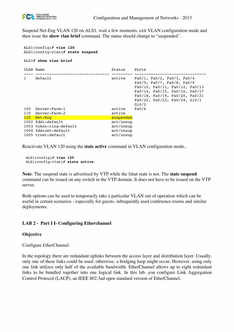
Configuration and Management of Networks - 2013
Suspend Net-Eng VLAN 120 on ALS1, wait a few moments, exit VLAN configuration mode and then issue the show vlan brief command. The status should change to “suspended”.
Reactivate VLAN 120 using the state active command in VLAN configuration mode..
Note: The suspend state is advertised by VTP while the lshut state is not. The state suspend command can be issued on any switch in the VTP domain. It does not have to be issued on the VTP server. Both options can be used to temporarily take a particular VLAN out of operation which can be useful in certain scenarios - especially for guests, infrequently used conference rooms and similar deployments. LAB 2 - Part I I- Configuring Etherchannel Objective Configure EtherChannel. In the topology there are redundant uplinks between the access layer and distribution layer. Usually, only one of these links could be used; otherwise, a bridging loop might occur. However, using only one link utilizes only half of the available bandwidth. EtherChannel allows up to eight redundant links to be bundled together into one logical link. In this lab, you configure Link Aggregation Control Protocol (LACP), an IEEE 802.3ad open standard version of EtherChannel.
CCNPv6 SWITCH
All contents are Copyright © 1992–2010 Cisco Systems, Inc. All rights reserved. This document is Cisco Public Information. Page 16 of 16
Reactivate all ports in ALS1 Net-Eng VLAN 120 using the no shutdown command in VLAN configuration mode..
ALS1(config)# vlan 120 ALS1(config-vlan)# no shutdown
You can also put a VLAN into “suspend” status. The "suspend" state is configured in the VLAN configuration mode using the command state suspend. Suspending a VLAN causes all ports in that VLAN throughout the VTP domain to stop transferring data.
Suspend Net-Eng VLAN 120 on ALS1, wait a few moments, exit VLAN configuration mode and then issue the show vlan brief command. The status should change to “suspended”.
ALS1(config)# vlan 120 ALS1(config-vlan)# state suspend ALS1# show vlan brief VLAN Name Status Ports ---- -------------------------------- --------- ------------------------------- 1 default active Fa0/1, Fa0/2, Fa0/3, Fa0/4 Fa0/5, Fa0/7, Fa0/8, Fa0/9 Fa0/10, Fa0/11, Fa0/12, Fa0/13 Fa0/14, Fa0/15, Fa0/16, Fa0/17 Fa0/18, Fa0/19, Fa0/20, Fa0/21 Fa0/22, Fa0/23, Fa0/24, Gi0/1 Gi0/2 100 Server-Farm-1 active Fa0/6 110 Server-Farm-2 active 120 Net-Eng suspended 1002 fddi-default act/unsup 1003 token-ring-default act/unsup 1004 fddinet-default act/unsup 1005 trnet-default act/unsup
Reactivate VLAN 120 using the state active command in VLAN configuration mode..
ALS1(config)# vlan 120 ALS1(config-vlan)# state active
Note: The suspend state is advertised by VTP while the lshut state is not. The state suspend command can be issued on any switch in the VTP domain. It does not have to be issued on the VTP server.
Both options can be used to temporarily take a particular VLAN out of operation which can be useful in certain scenarios - especially for guests, infrequently used conference rooms and similar deployments.
Step 14: Prepare for the next lab. Prepare for the next lab by removing all the VLAN information and configurations. The VLAN database and startup configuration need to be deleted.
Note: Traffic between VLANs must be routed. Inter-VLAN routing will be covered in a later lab.
Configuration and Management of Networks - 2013
1. Configure an 802.3ad LACP EtherChannel To configure a port channel as LACP, use the interface-level command channel-group number mode active. Active mode indicates that the switch actively tries to negotiate that link as LACP. For example to aggregate the ports of the link between DLS1 and ALS1 on ports Fa0/7 and Fa0/8 as an LACP EtherChannel you use the following commands on ALS1:
And apply similar commands in DLS1. Repeat the process for all the links between the distribution and access switches. Note: In order for the port channel to be successfully created all participating ports must have the same configuration after the creation of the Etherchannel configuration in the port-channel configuration mode is replicated in all ports belonging to that port-channel.
CCNPv6 SWITCH
All contents are Copyright © 1992–2010 Cisco Systems, Inc. All rights reserved. This document is Cisco Public Information. Page 4 of 6
<output omitted> ALS1# show spanning-tree VLAN0001 Spanning tree enabled protocol ieee Root ID Priority 32769 Address 0017.5a53.a380 Cost 19 Port 9 (FastEthernet0/9) Hello Time 2 sec Max Age 20 sec Forward Delay 15 sec Bridge ID Priority 32769 (priority 32768 sys-id-ext 1) Address 001d.4635.0c80 Hello Time 2 sec Max Age 20 sec Forward Delay 15 sec Aging Time 300 Interface Role Sts Cost Prio.Nbr Type ------------------- ---- --- --------- -------- ---------------------------- Fa0/7 Altn BLK 19 128.7 P2p Fa0/8 Altn BLK 19 128.8 P2p Fa0/9 Root FWD 19 128.9 P2p Fa0/10 Altn BLK 19 128.10 P2p Po1 Desg FWD 12 128.56 P2p
Step 4: Configure an 802.3ad LACP EtherChannel. a. In 2000, the IEEE passed 802.3ad, which is an open standard version of EtherChannel. Using the
previous commands, configure the link between DLS1 and ALS1 on ports Fa0/7 and Fa0/8 as an LACP EtherChannel. You must use a different port channel number on ALS1 than 1, because you already used that in the previous step. To configure a port channel as LACP, use the interface-level command channel-group number mode active. Active mode indicates that the switch actively tries to negotiate that link as LACP, as opposed to PAgP.
ALS1(config)# interface range fastEthernet 0/7 - 8 ALS1(config-if-range)# channel-group 2 mode active Creating a port-channel interface Port-channel 2 ALS1(config-if-range)# interface port-channel 2 ALS1(config-if)# switchport mode trunk
b. Apply a similar configuration on DLS1. Verify the configuration with the show etherchannel summary command.
ALS1# show etherchannel summary Flags: D - down P - in port-channel I - stand-alone s - suspended H - Hot-standby (LACP only) R - Layer3 S - Layer2 U - in use f - failed to allocate aggregator u - unsuitable for bundling w - waiting to be aggregated d - default port Number of channel-groups in use: 2 Number of aggregators: 2


![Lab8 : VLANssite.iugaza.edu.ps/nour/wp-content/uploads/Lab8_notes.pdfNETWORKS LAB [Lab8 : VLANs] 5 Switch 0: 1. Enter global conf. mode (managed switch). 2. Start creating VLANs by](https://img.pdfslide.us/doc/110x75/5acb75bf7f8b9a6b578e9c69/lab8-lab-lab8-vlans-5-switch-0-1-enter-global-conf-mode-managed-switch.jpg)