Embed Size (px)
Citation preview

Interconnecting CiscoNetworking Devices:AcceleratedVolume 1Version 2.0
CCNAX
Lab GuidePart Number: To be filled in later

Americas HeadquartersCisco Systems, Inc.San Jose, CA
Asia Pacific HeadquartersCisco Systems (USA) Pte. Ltd.Singapore
Europe HeadquartersCisco Systems International BVAmsterdam, The Netherlands
Cisco has more than 200 offices worldwide. Addresses, phone numbers, and fax numbers are listed on the Cisco Website atwww.cisco.com/go/offices.
Cisco and the Cisco logo are trademarks or registered trademarks of Cisco and/or its affiliates in the U.S. and other countries. Toview a list of Cisco trademarks, go to this URL: www.cisco.com/go/trademarks. Third party trademarks mentioned are the propertyof their respective owners. The use of the word partner does not imply a partnership relationship between Cisco and any othercompany. (1110R)
DISCLAIMER WARRANTY: THIS CONTENT IS BEING PROVIDED “AS IS.” CISCO MAKES AND YOU RECEIVE NOWARRANTIES IN CONNECTION WITH THE CONTENT PROVIDED HEREUNDER, EXPRESS, IMPLIED, STATUTORY OR INANY OTHER PROVISION OF THIS CONTENT OR COMMUNICATION BETWEEN CISCO AND YOU. CISCO SPECIFICALLYDISCLAIMS ALL IMPLIED WARRANTIES, INCLUDING WARRANTIES OF MERCHANTABILITY, NON-INFRINGEMENT ANDFITNESS FOR A PARTICULAR PURPOSE, OR ARISING FROM A COURSE OF DEALING, USAGE OR TRADE PRACTICE.This learning product may contain early release content, and while Cisco believes it to be accurate, it falls subject to thedisclaimer above.
© 2013 Cisco Systems, Inc.

Table of ContentsLab 1-1: Performing Switch Startup and Initial Configuration L-1
Visual Objective L-2Required Resources L-3Command List L-3Job Aids L-4Task 1: Perform a Reload and Verify that the Switch Is Unconfigured L-6Task 2: Configure the Switch with a Hostname and an IP Address L-8Task 3: Explore Context-Sensitive Help L-10Task 4: Improve the Usability of the CLI L-11
Lab 1-2: Troubleshooting Switch Media Issues L-13Visual Objective L-14Required Resources L-14Command List L-15Job Aids L-15Task 1: Lab Setup L-16Task 2: Troubleshoot Connectivity Between Computer PC1 and Switch SW1 L-17Task 3: Troubleshoot Connectivity Between Switch SW1 and the Branch Router L-18
Lab 2-1: Performing Initial Router Setup and Configuration L-19Visual Objective L-20Required Resources L-20Command List L-21Job Aids L-21Task 1: Inspect the Router Hardware and Software L-23Task 2: Create the Initial Router Configuration L-24Task 3: Improve the Usability of the CLI L-26Task 4: Discover Connected Neighbors with Cisco Discovery Protocol L-28
Lab 2-2: Connecting to the Internet L-31Visual Objective L-32Required Resources L-32Command List L-33Job Aids L-33Task 1: Configure a Manual IP Address and Static Default Route L-35Task 2: Configure a DHCP-Obtained IP Address L-39Task 3: Configure NAT L-42Task 4: Configure NAT with PAT L-47
Lab 3-1: Enhancing the Security of the Initial Configuration L-53Visual Objective L-54Required Resources L-54Command List L-55Job Aids L-56

Task 1: Add Password Protection L-57Task 2: Enable SSH Remote Access L-64Task 3: Limit Remote Access to Selected Network Addresses L-69Task 4: Configure a Login Banner L-71
Lab 3-2: Device Hardening L-73Visual Objective L-74Required Resources L-74Command List L-75Job Aids L-75Task 1: Disable Unused Ports L-77Task 2: Configure Port Security on a Switch L-78Task 3: Disable Unused Services L-81Task 4: Configure NTP L-83
Lab 3-3: Filtering Traffic with ACLs L-85Visual Objective L-86Required Resources L-86Command List L-87Job Aids L-87Task 1: Configure an ACL L-88Task 2: Lab Setup L-95Task 3: Troubleshoot an ACL L-96
Lab 4-1: Configure and Verify Basic IPv6 L-111Visual Objective L-112Required Resources L-112Command List L-113Job Aids L-113Task 1: Enable IPv6 on the Router L-114
Lab 4-2: Configure and Verify Stateless Autoconfiguration L-117Visual Objective L-117Required Resources L-118Command List L-118Job Aids L-119Task 1: Enable Stateless Autoconfiguration on the Router L-120
Lab 4-3: Configure and Verify IPv6 Routing L-125Visual Objective L-125Command List L-126Job Aids L-127Task 1: Task: Enable IPv6 Static Routing L-128
Lab 5-1: Configuring Expanded Switched Networks L-131Visual Objective L-132Required Resources L-132Command List L-133
ii Interconnecting Cisco Networking Devices: Accelerated © 2013 Cisco Systems, Inc.

Job Aids L-133Task 1: Configure a VLAN L-135Task 2: Configure the Link Between Switches as a Trunk L-140Task 3: Configure a Trunk Link on the Router L-141
Lab 5-2: Configuring DHCP Server L-145Visual Objective L-146Required Resources L-146Command List L-146Job Aids L-147Task 1: Configure DHCP Pools L-149Task 2: Exclude Specific IP Addresses from DHCP Pools L-153Task 3: Configure DHCP Relay Agent L-154Task 4: Manually Assign IP Addresses L-155
Lab 5-3: Troubleshooting VLANs and Trunks L-159Visual Objective L-159Required Resources L-160Command List L-160Job Aids L-161Task 1: Troubleshoot VLAN Connectivity L-163Task 2: Troubleshoot Trunk Connectivity Between the Switches L-167
Lab 5-4: Optimizing STP L-173Visual Objective L-173Required Resources L-174Command List L-174Job Aids L-175Task 1: Verify STP Operation L-177Task 2: Influence Root Bridge Selection L-180Task 3: Implement STP PortFast L-183Task 4: Implement STP BPDU Guard L-185
Lab 5-5: Configuring EtherChannel L-189Visual Objective L-189Required Resources L-190Command List L-190Job Aids L-191Task 1: Configure EtherChannel L-193Task 2: Verify EtherChannel Redundancy L-197
Lab 6-1: Troubleshooting IP Connectivity L-201Visual Objective L-201Required Resources L-202Command List L-202Job Aids L-203Task 1: Troubleshoot the Default Route L-205
© 2013 Cisco Systems, Inc. Lab Guide iii

Task 2: Troubleshoot an ACL L-209Task 3: Troubleshoot the Default Gateway and Name Resolution Settings L-212
Lab 7-1: Configuring and Troubleshooting a Serial Connection L-221Visual Objective L-221Required Resources L-222Command List L-222Job Aids L-223Task 1: Troubleshoot PPP L-225Task 2: Enable HDLC Encapsulation L-229
Lab 7-2: Establishing a Frame Relay WAN L-233Visual Objective L-233Required Resources L-234Command List L-234Job Aids L-235Task 1: Configure and Verify Basic Frame Relay L-237Task 2: Configure and Verify Frame Relay Subinterfaces L-240Task 3: Remove Frame Relay Configuration L-243
Lab 7-3: Establishing a GRE Tunnel L-245Visual Objective L-245Required Resources L-246Command List L-246Job Aids L-247Task 1: Configure and Verify a GRE Tunnel L-249
Lab 8-1: Implementing EIGRP L-251Visual Objective L-251Required Resources L-252Command List L-252Job Aids L-253Task 1: Configure and Verify EIGRP L-255Task 2: Investigate Neighbor Events L-259Task 3: Configure and Verify EIGRP over a GRE Tunnel L-260
Lab 8-2: Troubleshooting EIGRP L-267Visual Objective L-267Required Resources L-268Command List L-268Job Aids L-269Task 1: Troubleshoot Basic Connectivity L-272Task 2: Troubleshoot EIGRP Neighbors L-274Task 3: Troubleshoot Routing Table Issues L-276
Lab 8-3: Implementing EIGRP for IPv6 L-281Visual Objective L-281Required Resources L-282
iv Interconnecting Cisco Networking Devices: Accelerated © 2013 Cisco Systems, Inc.

Command List L-282Job Aids L-283Task 1: Enable IPv6 on the Interfaces L-285Task 2: Enable IPv6 EIGRP L-286
Lab 9-1: Implementing OSPF L-291Visual Objective L-291Required Resources L-292Command List L-292Job Aids L-293Task 1: Configure OSPF L-296
Lab 9-2: Configuring Multiarea OSPF L-299Visual Objective L-299Required Resources L-300Command List L-300Job Aids L-301Task 1: Configure Multiarea OSPF L-303Task 2: Verify Multiarea OSPF L-304
Lab 9-3: Troubleshooting Multiarea OSPF L-309Visual Objective L-309Required Resources L-310Command List L-310Job Aids L-311Task 1: Troubleshoot OSPF Neighbor Issues L-314Task 2: Troubleshoot OSPF Routing Table Issues L-320
Lab 9-4: Configuring OSPF for IPv6 L-323Visual Objective L-323Required Resources L-324Command List L-324Job Aids L-325Task 1: Enable OSPFv3 L-327
Lab 10-1: SNMP and Syslog Basic Configuration L-333Visual Objective L-333Required Resources L-334Command List L-335Job Aids L-335Task 1: Configure Router for SNMP Access L-338Task 2: Configure Router for Syslog L-340
Lab 10-2: Analyzing NetFlow Data L-343Visual Objective L-343Required Resources L-343Command List L-343Job Aids L-343
© 2013 Cisco Systems, Inc. Lab Guide v

Task 1: Analyze NetFlow Data L-343
Lab 10-3: Managing Cisco Devices and Licensing L-351Visual Objective L-351Required Resources L-352Command List L-352Job Aids L-353Task 1: Lab Setup L-356Task 2: Router Password Recovery L-357Task 3: Backing Up a Cisco IOS Image L-358Task 4: Manage the Configuration File L-360Task 5: Verify Licensing L-362
Lab Answer Keys L-363Lab 1-1: Performing Switch Startup and Initial Configuration L-363Lab 1-2: Troubleshooting Switch Media Issues L-370Lab 2-1: Performing Initial Router Setup and Configuration L-373Lab 2-2: Connecting to the Internet L-375Lab 3-1: Enhancing the Security of the Initial Configuration L-378Lab 3-2: Device Hardening L-381Lab 3-3: Filtering Traffic with ACLs L-384Lab 4-1: Configure and Verify Basic IPv6 L-385Lab 4-2: Configure and Verify Stateless Autoconfiguration L-386Lab 4-3: Configure and Verify IPv6 Routing L-386Lab 5-1: Configuring Expanded Switched Networks L-386Lab 5-2: Configuring DHCP Server L-389Lab 5-3: Troubleshooting VLANs and Trunks L-391Lab 5-4: Optimizing STP L-393Lab 5-5: Configuring EtherChannel L-395Lab 6-1: Troubleshooting IP Connectivity L-396Lab 7-1: Configuring and Troubleshooting a Serial Connection L-397Lab 7-2: Establishing a Frame Relay WAN L-398Lab 7-3: Establishing a GRE Tunnel L-400Lab 8-1: Implementing EIGRP L-401Lab 8-2: Troubleshooting EIGRP L-403Lab 8-3: Implementing EIGRP for IPv6 L-404Lab 9-1: Implementing OSPF L-406Lab 9-2: Configuring Multiarea OSPF L-406Lab 9-3: Troubleshooting Multiarea OSPF L-407Lab 9-4: Configuring OSPF for IPv6 L-409Lab 10-1: SNMP and Syslog Basic Configuration L-410Lab 10-2: Analyzing NetFlow Data L-411Lab 10-3: Managing Cisco Devices and Licensing L-411
vi Interconnecting Cisco Networking Devices: Accelerated © 2013 Cisco Systems, Inc.

Lab 1-1: Performing SwitchStartup and InitialConfiguration
Activity OverviewObjectivesIn this activity, you will observe the switch boot procedure and perform basic switch configuration. Afteryou have completed this activity, you will be able to meet these objectives:
Restart the switch and verify the initial configuration messages
Complete the initial configuration of the Cisco Catalyst switch
Explore context-sensitive help
Improve the usability of the CLI

Visual ObjectiveThe figure illustrates what you will accomplish in this activity.
Visual Objective for Lab 1-1: PerformingSwitch Startup and Initial Configuration
Server
PC1
PC2
SW1
SW2
Branch
HQ
© 2013 Cisco Systems, Inc.
Detailed Visual ObjectivePerform switch startup
and initial configuration.
PC1 SW1
© 2013 Cisco Systems, Inc.
L-2 Interconnecting Cisco Networking Devices: Accelerated © 2013 Cisco Systems, Inc.

Required ResourcesNo additional resources are required for this lab.
Command ListThe table describes the commands that are used in this activity. The commands are listed in alphabeticalorder so that you can easily locate the information that you need. Refer to this list if you need configurationcommand assistance during the lab activity.
Cisco IOS Switch CommandsCommand Description
? or help In user EXEC mode, lists the subset of commands that areavailable at that level
clock set Manages the system clock
configure terminal Activates the configuration mode from the terminal
copy running-config destination Copies the switch running configuration file to another destination.A typical destination is the startup configuration.
delete name Deletes a file from flash memory
do command Executes user EXEC or privileged EXEC commands from globalconfiguration mode or other configuration modes or submodes, inany configuration mode
enable Activates privileged EXEC mode. In privileged EXEC mode, morecommands are available. This command requires you to enter theenable password if an enable password is configured.
end Terminates configuration mode
erase startup-config Erases the startup configuration that is stored in nonvolatilememory
exit Exits the current configuration mode
history size number Sets the number of lines that are held in the history buffer forrecall. Two separate buffers are used: one for EXEC modecommands and the other for configuration mode commands
hostname hostname Sets the system name, which forms part of the prompt
interface vlan 1 Enters interface configuration mode for VLAN 1 to set the switchmanagement IP address
ip address ip-address subnet-mask Sets the IP address and mask of the interface
line console 0 Enters line console configuration mode
logging synchronous Synchronizes unsolicited messages and debugs privileged EXECcommand output with solicited device output and prompts for aspecific console port line or vty line
reload Restarts the switch and reloads the Cisco IOS operating systemand configuration
show clock Displays the system clock
© 2013 Cisco Systems, Inc. Lab Guide L-3

Command Description
show flash: Displays the layout and contents of a flash memory file system
show startup-config Displays the startup configuration settings that are saved inNVRAM
show terminal Displays the current settings for the terminal
show version Displays the configuration of the switch hardware and the varioussoftware versions
Job AidsThese job aids are available to help you complete the lab activity.
The table shows the hardware that is used in the lab and the operating system that is running on the devices.
Device Hardware Operating System
SW1 Catalyst 2960 Series Switch c2960-lanbasek9-mz.150-1.SE3
PC1 Any PC Microsoft Windows 7
There are no console or enable passwords set for the router and switch in the initial lab setup. The tableshows the username and password that are used to access PC1.
Device Username Password
PC1 Administrator admin
L-4 Interconnecting Cisco Networking Devices: Accelerated © 2013 Cisco Systems, Inc.

Topology and IP Addressing
Devices are connected by Ethernet connections. The figure illustrates the interface identification and IPaddresses that are used in this lab setup.
Topology and IP Addressing
10.1.1.100 10.1.1.11
PC1 SW1Fa0/1
© 2013 Cisco Systems, Inc.
The table shows the interface identification and IP addresses that are used in this lab setup.
Device Interface IP Address Subnet Mask
SW1 VLAN1 10.1.1.11 255.255.255.0
PC1 Ethernet adapter local areaconnection
10.1.1.100 255.255.255.0
© 2013 Cisco Systems, Inc. Lab Guide L-5

Setting the IP Address on a PC
On a PC, click Start and choose Control Panel. Click Change Adapter Settings and then right-clickLocal Area Network. Choose Properties. When you are presented with the Local Area ConnectionProperties dialog, click Internet Protocol version 4 (TCP/IPv4) and then click Properties. In the InternetProtocol Version 4 (TCP/IPv4) Properties window, click the Use the Following IP Address radio buttonand enter the appropriate IP address, subnet mask, and default gateway.
Task 1: Perform a Reload and Verify that theSwitch Is UnconfiguredIn this task, you will use the erase startup-config command to ensure that the switch has no priorconfiguration in the startup-config file. You will then reload the switch software and observe the output thatis generated during the reload. Finally, you will investigate the properties of the switch.
Activity ProcedureComplete the following steps:
Step 1
Access the CLI of switch SW1 and enter user EXEC mode.
You will be provided with information about how to access the lab equipment.
L-6 Interconnecting Cisco Networking Devices: Accelerated © 2013 Cisco Systems, Inc.

Step 2
To see the effect of entering a privileged-level command in user EXEC mode, enter the command erasestartup-config.
What was the result of issuing the command in an incorrect EXEC mode?
Step 3
Enter privileged EXEC mode.
How do you know if you are in privileged EXEC mode and not user EXEC mode?
Step 4
Erase the startup configuration. Because the switch also stores a small part of the configuration in the file,vlan.dat, stored in flash memory, delete it before performing a reload. Observe the output during the reload.
Step 5
Press Enter when the switch boots and skip the initial configuration dialog. You will know when the switchhas finished booting when you see "Press RETURN to get started!" in the console output.
How do you know that the startup configuration has been erased?
Step 6
Using the appropriate show command, investigate the switch model number, software version, and amountof RAM and flash memory.
Activity VerificationYou have completed this task when you attain these results:
You performed a switch reload.
You verified that the switch is unconfigured.
© 2013 Cisco Systems, Inc. Lab Guide L-7

Task 2: Configure the Switch with a Hostnameand an IP AddressIn this task, you will configure the switch with a hostname and an IP address.
Activity ProcedureComplete the following steps:
Step 1
Change the hostname of the switch to SW1.
Step 2
Assign an IP address to the VLAN 1 interface on switch SW1. Be sure that you assign the correct IPaddress, as described in the Job Aids section in the beginning of the lab document.
Note Configuring the IP address on the switch is not mandatory to start the switch running, but it is necessaryfor remote management access to the switch.
Step 3
Access the PC1. Use the username and password that is described in the Job Aids section in order to log in.
L-8 Interconnecting Cisco Networking Devices: Accelerated © 2013 Cisco Systems, Inc.

Step 4
Assign the IP address of PC1, as listed in the Job Aids section. Leave the default gateway empty.
Step 5
From PC1, ping the VLAN 1 IP address of SW1 to confirm Layer 3 connectivity.
Activity VerificationYou have completed this task when you attain these results:
You configured the switch with a hostname and a VLAN 1 IP address.
You configured PC1 with the correct IP address.
Your ping from PC1 to the VLAN 1 IP address of SW1 was successful.
© 2013 Cisco Systems, Inc. Lab Guide L-9

Task 3: Explore Context-Sensitive HelpIn this task, you will use context-sensitive help to locate commands and complete command syntax.
Activity ProcedureComplete the following steps:
Step 1
On switch SW1, enter privileged EXEC mode and enter ? (or help) to list the available commands.
Step 2
Using the ? command, set the clock on the switch to the current time and date.
Note Pressing the Tab key automatically completes the command if the characters that you have entered arenot ambiguous.
Step 3
Verify the current date and time using the appropriate show command.
Step 4
Type the following comment line at the prompt and then press Enter:
!ths command changuw the clck sped for the swch
Note An exclamation point (!) at the beginning of the line indicates that you are entering a comment. Thecomment will not be part of the switch configuration. Comments are a great help when you are workingon a configuration in a text editor and plan to upload it to a device.
Step 5
Press Ctrl-P or press the Up Arrow key to see the previous line. Use the editor commands Ctrl-A, Ctrl-F,Ctrl-E, and Ctrl-B to move along the line, and use the Backspace key to delete unwanted characters.Using the editing commands, correct the comment line to read:
!This command changes the clock speed for the switch.
Activity VerificationYou have completed this task when you attain these results:
You used the system help and command-completion functions.
You used the built-in editor and the keystrokes for cursor navigation.
L-10 Interconnecting Cisco Networking Devices: Accelerated © 2013 Cisco Systems, Inc.

Task 4: Improve the Usability of the CLIIn this task, you will enter commands to improve the usability of the CLI. You will increase the number oflines in the history buffer, increase the inactivity timer on the console port, and stop the attempted nameresolution of mistyped commands.
Activity ProcedureComplete the following steps:
Step 1
Using the show terminal command, verify that history is enabled, and determine the current history size forthe console line.
Step 2
Change the history size to 100 for the console line and verify that the change has taken place.
Note Alternatively, you could use the begin keyword. You will see the output beginning from the first match.
Step 3
The no ip domain lookup command disables the resolution of symbolic names. If you mistype a command,the system will not try to translate it into an IP address (it will take about 5 seconds to time out). Disable IPdomain lookup.
Step 4
The default console access EXEC timeout is set to 10 minutes. After 10 minutes of inactivity, the user isdisconnected from console access and is required to reconnect. Change this timer to 60 minutes.
Note Make sure that you are in console line configuration mode. To execute user EXEC or privileged EXECcommands from global configuration mode or other configuration modes or submodes, use the docommand in any configuration mode.
Step 5
The logging synchronous command synchronizes unsolicited messages and debugs privileged EXECcommand output with the input from the CLI. If you are in the middle of typing a command, statusmessages will appear where you are typing. Enable synchronous logging on line console 0.
Step 6
Save your running configuration to the startup configuration.
© 2013 Cisco Systems, Inc. Lab Guide L-11

Activity VerificationYou have completed this task when you attain these results:
You changed the history buffer size.
You disabled resolution of symbolic names.
You set the inactivity timeout on the console line to 60 minutes.
You enabled synchronous logging on the console line.
You saved the running configuration to the startup configuration file.
L-12 Interconnecting Cisco Networking Devices: Accelerated © 2013 Cisco Systems, Inc.
Lab 1-2: TroubleshootingSwitch Media Issues
Activity OverviewObjectivesIn this activity, you will use troubleshooting guidelines to isolate and correct switch media issues. Aftercompleting this activity, you will be able to meet these objectives:
Follow troubleshooting guidelines to determine the source of connectivity problems between acomputer and a switch, and fix them
Follow troubleshooting guidelines to determine the source of connectivity problems between a routerand a switch, and fix them

Visual ObjectiveThe figure illustrates what you will accomplish in this activity.
Visual Objective for Lab 1-2: TroubleshootingSwitch Media Issues
Server
PC1
PC2
SW1
SW2
Branch
HQ
© 2013 Cisco Systems, Inc.
Detailed Visual Objective
SW1PC1
Branch
Troubleshooting Task 1
Troubleshooting Task 2
© 2013 Cisco Systems, Inc.
Required ResourcesThese are the resources and equipment that are required to complete this activity:
Successful completion of Lab 1-1: Performing Switch Startup and Initial Configuration
L-14 Interconnecting Cisco Networking Devices: Accelerated © 2013 Cisco Systems, Inc.

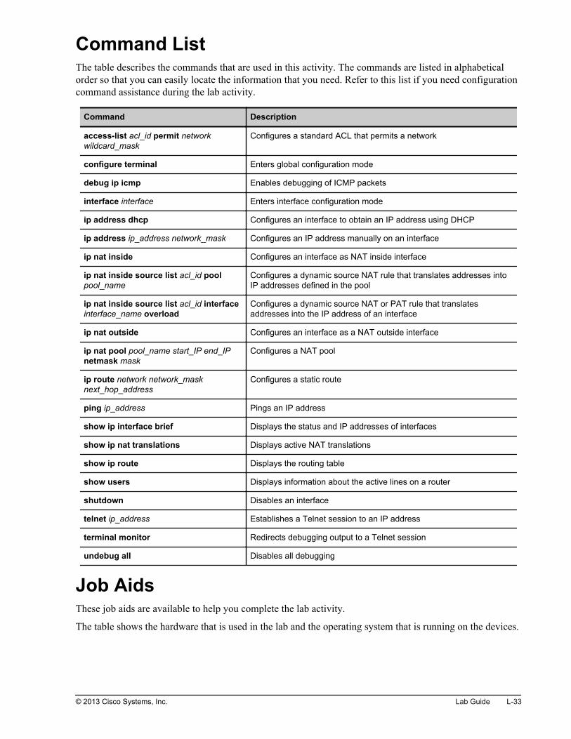
Command ListThe table describes the commands that are used in this activity. The commands are listed in alphabeticalorder so that you can easily locate the information that you need. Refer to this list if you need configurationcommand assistance during the lab activity.
CommandsCommand Description
configure terminal Enters global configuration mode
copy running-config startup-config Saves the running configuration into NVRAM as the startupconfiguration
duplex full Enables full duplex on an interface
enable Enters the privileged EXEC mode command interpreter
interface FastEthernet 0/13 Specifies interface FastEthernet 0/13 and enters interfaceconfiguration mode
shutdown/no shutdown Disables or enables an interface
ping ip-address Uses ICMP echo requests and ICMP echo replies todetermine whether a remote host is reachable
show interfaces FastEthernet 0/13 Displays information about interface FastEthernet 0/13
show ip interface brief Displays a brief summary of the interfaces on a device, which is usefulfor quickly checking the status of the device
Job AidsThese job aids are available to help you complete the lab activity.
The table shows the hardware that is used in the lab and the operating system that is running on the devices.
Device Hardware Operating System
Branch Cisco 2901 Integrated Services Router c2900-universalk9-mz.SPA.152-4.M1
SW1 Catalyst 2960 Series Switch c2960-lanbasek9-mz.150-1.SE3
PC1 Any PC Microsoft Windows 7
There are no console or enable passwords set for the router and switch in the initial lab setup. The tableshows the username and password that are used to access PC1.
Device Username Password
PC1 Administrator admin
Topology and IP Addressing
Devices are connected with Ethernet connections. The figure illustrates the interface identification and IPaddresses that are used in this lab setup.
© 2013 Cisco Systems, Inc. Lab Guide L-15

Topology and IP Addressing
PC1 SW1
Fa0/1
10.1.1.100 10.1.1.11
Fa0/13
Gi0/0 10.1.1.1
© 2013 Cisco Systems, Inc.
The table shows the interface identification and IP addresses that are used in this lab setup.
Device Interface IP Address/Subnet Mask
Branch Gi0/0 10.1.1.1/24
SW1 VLAN1 10.1.1.11/24
PC1 Ethernet adapter local area connection 10.1.1.100/24
Task 1: Lab SetupIn this setup task, you will load the configuration from the switch flash drive.
Activity ProcedureComplete these steps:
Step 1
Access the CLI of switch SW1.
You will be provided with information about accessing the lab equipment.
L-16 Interconnecting Cisco Networking Devices: Accelerated © 2013 Cisco Systems, Inc.

Step 2
Load the configuration file tshoot_media_issues_start.cfg from the flash drive of the switch.
SW1#copy flash:tshoot_sw_media.cfg run
At this point, you have loaded a configuration file that includes your trouble tickets, presented in Tasks 2and 3.
Activity VerificationYou have completed this task when you attain this result:
You loaded a configuration file from the switch flash drive.
Task 2: Troubleshoot Connectivity BetweenComputer PC1 and Switch SW1In this task, you will troubleshoot connectivity problems between switch SW1 and computer PC1.
Activity ProcedureComplete the following steps:
Step 1
John calls you about an issue that he is experiencing while using PC1. He says that PC1 has no networkconnectivity, and he insists that somebody unplugged his computer from the switch. The senior engineersare out. You are the only one who can solve this problem right now. You have access only to switch SW1.
Determine whether or not you can ping PC1 from switch SW1. The IP address of PC1 is listed in the JobAids section of this document. Is there Layer 3 connectivity between the computer and the switch?
Step 2
What is the status of interface FastEthernet0/1 on switch SW1, which connects to the PC1? What does thisstatus mean?
Note Use the ? command and the Tab key to help you with the command syntax.
© 2013 Cisco Systems, Inc. Lab Guide L-17

Step 3
Correct the issue so that John can continue his work.
Do not forget to verify Layer 3 connectivity between PC1 and SW1.
Step 4
Save the configuration of switch SW1.
Why is it important at this stage to save the configuration?
Activity VerificationYou have completed this task when you attain this result:
You identified and corrected the problem that was reported by the user on PC1.
Task 3: Troubleshoot Connectivity BetweenSwitch SW1 and the Branch RouterIn this task, you will troubleshoot connectivity problems between the Branch router and switch SW1. Youwill correct the existing problem.
Activity ProcedureComplete the following steps:
Step 1
Your colleague informs you that switch SW1 is showing messages about duplex mismatch and they areunable to prevent the messages. The senior engineers went out for lunch and left you alone to resolve thisissue. How do you solve the problem indicated by this message?
Using the appropriate show commands from the Command List section, identify the status of interfaceFastEthernet0/13, which connects to the Branch router.
Step 2
Correct the issue that you identified. Do not forget to save the changes that you made.
Activity VerificationYou have completed this task when you attain this result:
You identified and corrected the connectivity problem.
L-18 Interconnecting Cisco Networking Devices: Accelerated © 2013 Cisco Systems, Inc.

Lab 2-1: Performing InitialRouter Setup andConfiguration
Activity OverviewObjectivesIn this activity, you will observe the router boot procedure and perform basic router configuration. Aftercompleting this activity, you will be able to meet these objectives:
Inspect router hardware and software
Perform initial router configuration
Improve the usability of the CLI
Use Cisco Discovery Protocol to discover how devices are interconnected

Visual ObjectiveThe figure illustrates what you will accomplish in this activity.
Visual Objective for Lab 2-1: Performing InitialRouter Setup and Configuration
Server
PC1
PC2
SW1
SW2
Branch
HQ
© 2013 Cisco Systems, Inc.
Detailed Visual Objective
PC1
SW1
BranchVerify the router
and its settings.Perform router
initial configuration.
Use Cisco Discovery
Protocol to discover how
devices are interconnected.
© 2013 Cisco Systems, Inc.
Required ResourcesNo additional resources are required for this lab.
L-20 Interconnecting Cisco Networking Devices: Accelerated © 2013 Cisco Systems, Inc.

Command ListThe table describes the commands that are used in this activity. The commands are listed in alphabeticalorder so that you can easily locate the information that you need. Refer to this list if you need configurationcommand assistance during the lab activity.
Cisco IOS Router CommandsCommand Description
configure terminal Activates the configuration mode from the terminal.
copy running-config destination Copies the running configuration file to another destination. Atypical destination is the startup configuration.
description Adds a descriptive comment to the configuration of an interface.
enable Activates privileged EXEC mode. In privileged EXEC mode, morecommands are available.
erase startup-config Erases the startup configuration that is stored in nonvolatilememory.
exec-timeout Sets the interval before the user session is disconnected whenidle.
hostname hostname Sets the system name, which forms part of the prompt.
interface type module/slot/port Specifies an interface and enters interface configuration mode.
ip address ip-address subnet-mask Sets the IP address and mask of the interface.
[no] ip domain lookup Enables or disables DNS resolution of symbolic names.
line console 0 Enters line console configuration mode.
logging synchronous Synchronizes the display of router output messages with thecommand-line prompt.
ping ip_address Uses ICMP echo requests and ICMP echo replies to determinewhether a remote host is reachable.
reload Restarts the router and reloads the Cisco IOS operating system.
show cdp Displays global Cisco Discovery Protocol information.
show cdp neighbors [detail] Displays brief information about discovered neighboring Ciscodevices. If the keyword detail is used, detailed information aboutdiscovered devices is displayed.
show interfaces Displays information about all of the device interfaces.
show startup-config Displays the startup configuration settings that are saved innonvolatile memory.
show version Displays the configuration of the router hardware and thevarious software versions.
[no] shutdown Disables or enables an interface.
Job AidsThese job aids are available to help you complete the lab activity.
© 2013 Cisco Systems, Inc. Lab Guide L-21

The table shows the hardware that is used in the lab and the operating system that is running on the devices.
Device Hardware Operating System
Branch Cisco 2901 Integrated Services Router c2900-universalk9-mz.SPA.152-4.M1
SW1 Catalyst 2960 Series Switch c2960-lanbasek9-mz.150-1.SE3
PC1 Any PC Microsoft Windows 7
There are no console or enable passwords set for the router and switch in the initial lab setup. The tableshows the username and password that are used to access PC1.
Device Username Password
PC1 Administrator admin
Topology and IP Addressing
Devices are connected with Ethernet connections. The figure illustrates the interface identification and IPaddresses that are used in this lab setup.
Topology and IP Addressing
PC1 SW1
Fa0/1
10.1.1.100 10.1.1.11
Fa0/13
Gi0/0 10.1.1.1
© 2013 Cisco Systems, Inc.
The table shows the interface identification and IP addresses that are used in this lab setup.
Device Interface IP Address/Subnet Mask
Branch Gi0/0 10.1.1.1/24
SW1 VLAN1 10.1.1.11/24
PC1 Ethernet adapter local area connection 10.1.1.100/24
L-22 Interconnecting Cisco Networking Devices: Accelerated © 2013 Cisco Systems, Inc.

Task 1: Inspect the Router Hardware andSoftwareIn this task, you will first inspect the router hardware and software properties. You will verify that a startupconfiguration exists and delete it. You will then reload the router and observe the output that is generatedduring the reload.
Activity ProcedureComplete the following steps:
Step 1
Access the CLI of router Branch and enter privileged EXEC mode.
Step 2
Use the correct verification command to display hardware and software properties. Find and write down thefollowing information:
Router model
Serial number
RAM
Flash
Software version
Use command show version in privileged EXEC mode on the Branch router to display information aboutthe currently loaded software, along with hardware and device information.
Router#show versionCisco IOS Software, C2900 Software (C2900-UNIVERSALK9-M), Version 15.2(4)M1, RELEASE SOFTWARE (fc1)Technical Support: http://www.cisco.com/techsupportCopyright (c) 1986-2012 by Cisco Systems, Inc.Compiled Thu 26-Jul-12 20:54 by prod_rel_teamROM: System Bootstrap, Version 15.0(1r)M15, RELEASE SOFTWARE (fc1)Router uptime is 15 minutesSystem returned to ROM by reload at 17:06:50 UTC Thu Nov 22 2012System restarted at 17:09:24 UTC Thu Nov 22 2012System image file is "flash0:c2900-universalk9-mz.SPA.152-4.M1.bin"Last reload type: Normal ReloadLast reload reason: Reload Command<output omitted>Cisco CISCO2901/K9 (revision 1.0) with 483328K/40960K bytes of memory.Processor board ID FCZ1642C5XJ2 Gigabit Ethernet interfaces1 Serial(sync/async) interface1 terminal lineDRAM configuration is 64 bits wide with parity enabled.255K bytes of non-volatile configuration memory.250880K bytes of ATA System CompactFlash 0 (Read/Write)<output omitted>
© 2013 Cisco Systems, Inc. Lab Guide L-23

Step 3
Use the correct show command to verify that the router has a startup configuration. If it has, erase thestartup configuration by issuing the erase startup-config command.
Router#erase startup-configErasing the nvram filesystem will remove all configuration files! Continue? [confirm][OK]Erase of nvram: completeRouter#
After you have erased the startup configuration, verify that it no longer exists.
Router#show startup-configstartup-config is not present
Step 4
Reload the router and observe the console output during startup.
Router#reloadProceed with reload? [confirm]Sep 11 11:31:16.663: %SYS-5-RELOAD: Reload requested by console. Reload Reason: Reload Command.System Bootstrap, Version 15.0(1r)M1, RELEASE SOFTWARE (fc1)Technical Support: http://www.cisco.com/techsupportCopyright (c) 2009 by cisco Systems, Inc.Total memory size = 512 MB - On-board = 512 MB, DIMM0 = 0 MBCISCO2901/K9 platform with 524288 Kbytes of main memoryMain memory is configured to 72/-1(On-board/DIMM0) bit mode with ECC enabledReadonly ROMMON initializedprogram load complete, entry point: 0x80803000, size: 0x1b340program load complete, entry point: 0x80803000, size: 0x1b340IOS Image Load Test<output omitted>
Activity VerificationYou have completed this task when you attain these results:
You collected hardware and software device information.
You erased the startup configuration.
You reloaded the router and observed the startup output.
Task 2: Create the Initial Router ConfigurationIn this task, you will skip the initial configuration dialog and proceed with manual configuration. You willconfigure system parameters and router interfaces. You will then verify connectivity.
L-24 Interconnecting Cisco Networking Devices: Accelerated © 2013 Cisco Systems, Inc.

Activity ProcedureComplete the following steps:
Step 1
Skip the initial configuration dialog, terminate the autoinstall, and enter privileged EXEC mode.
Step 2
Set the router host name to Branch. The prompt will reflect the new hostname.
Step 3
Enable interface GigabitEthernet0/0 and set its description to Link to LAN Switch.
Step 4
Configure the IP address 10.1.1.1 on the interface. Use subnet mask of 255.255.255.0.
Step 5
Return to the privileged EXEC command and verify GigabitEthernet0/0 interface status, interfacedescription, and correct IP address assignment by using a suitable verification command.
Branch#show interfaces GigabitEthernet 0/0GigabitEthernet0/0 is up, line protocol is up Hardware is CN Gigabit Ethernet, address is 5475.d08e.9ad8 (bia 5475.d08e.9ad8) Description: Link to LAN Switch Internet address is 10.1.1.1/24 MTU 1500 bytes, BW 100000 Kbit/sec, DLY 100 usec, reliability 255/255, txload 1/255, rxload 1/255 Encapsulation ARPA, loopback not set Keepalive set (10 sec) Full Duplex, 100Mbps, media type is RJ45 <output omitted>
Step 6
Save the current configuration on the Branch router.
Activity VerificationYou have completed this task when you attain these results:
Step 1
The console prompt shows the configured hostname:
Branch#
© 2013 Cisco Systems, Inc. Lab Guide L-25

Step 2
You verified IP connectivity between router Branch and PC1 by using ICMP ping:
Branch#ping 10.1.1.100Type escape sequence to abort.Sending 5, 100-byte ICMP Echos to 10.1.1.100, timeout is 2 seconds:.!!!!Success rate is 80 percent (4/5), round-trip min/avg/max = 1/1/4 ms
The ping should be successful.
Note The ping might fail due to slow STP convergence on the SW1 switch. If the ping fails, try to issue anotherping after a few seconds.
Note The first ICMP packet could time out because ARP needs to obtain Layer 2 addressing before thepacket can be sent out of the interface.
Task 3: Improve the Usability of the CLIIn this task, you will improve the CLI experience by increasing the inactivity timer on the console line andby disabling the resolution of symbolic names.
Activity ProcedureComplete the following steps:
Step 1
Change the EXEC timeout on the console line, which is set to 10 minutes by default, to a value of 60minutes.
L-26 Interconnecting Cisco Networking Devices: Accelerated © 2013 Cisco Systems, Inc.

Step 2
Verify the EXEC timeout value on the Branch router:
Branch#show line console 0 Tty Line Typ Tx/Rx A Modem Roty AccO AccI Uses Noise Overruns Int* 0 0 CTY - - - - - 0 0 0/0 -Line 0, Location: "", Type: ""Length: 24 lines, Width: 80 columnsStatus: PSI Enabled, Ready, Active, Automore OnCapabilities: noneModem state: ReadyRJ45 Console is in useUSB Console baud rate = 9600Modem hardware state: CTS* noDSR DTR RTSSpecial Chars: Escape Hold Stop Start Disconnect Activation ^^x none - - noneTimeouts: Idle EXEC Idle Session Modem Answer Session Dispatch 01:00:00 never none not set Idle Session Disconnect Warning never Login-sequence User Response 00:00:30 Autoselect Initial Wait not set<output omitted>
Step 3
Improve the readability of the console access by synchronizing unsolicited messages and debug outputswith the input from the CLI.
Step 4
Disable the resolution of symbolic names to prevent the system from attempting to translate a mistypedcommand into an IP address.
Step 5
Save the configured changes to the startup configuration.
Activity VerificationYou have completed this task when you attain these results:
You have set the inactivity timeout on the console line to 60 minutes.
You have enabled synchronous logging on the console line.
You have disabled resolution of symbolic names.
© 2013 Cisco Systems, Inc. Lab Guide L-27

Task 4: Discover Connected Neighbors withCisco Discovery ProtocolIn this task, you will use Cisco Discovery Protocol to obtain information about directly connected Ciscodevices. You will gather information about neighbor capabilities and IP addresses and discover how devicesare interconnected.
Activity ProcedureComplete the following steps:
Step 1
On the Branch router, issue the show cdp command to verify that Cisco Discovery Protocol is enabled andto display its global information.
Branch#show cdpGlobal CDP information: Sending CDP packets every 60 seconds Sending a holdtime value of 180 seconds Sending CDPv2 advertisements is enabled
L-28 Interconnecting Cisco Networking Devices: Accelerated © 2013 Cisco Systems, Inc.

Step 2
Enter the Cisco Discovery Protocol verification command to display all known neighboring Cisco devices.
Write down the information about the discovered neighbors in the table:
Device ID Platform Local Interface Remote Interface (PortID)
#
#
The information that you gather about the local and remote interfaces that are used reveals how neighboringdevices are physically interconnected.
On the Branch router, use the show cdp neighbors command to display all neighboring Cisco devices:
Branch#show cdp neighborsCapability Codes: R - Router, T - Trans Bridge, B - Source Route Bridge S - Switch, H - Host, I - IGMP, r - Repeater, P - Phone, D - Remote, C - CVTA, M - Two-port Mac RelayDevice ID Local Intrfce Holdtme Capability Platform Port IDSW1 Gig 0/0 158 S I WS-C2960- Fas 0/13
Use the Cisco Discovery Protocol verification command with the keyword detail to display additionalinformation about other Cisco devices. Write down the IP address of a neighboring switch, with exactinformation about its platform and software version.
Branch#show cdp neighbors detail-------------------------Device ID: SW1Entry address(es): IP address: 10.1.1.11Platform: cisco WS-C2960-24TT-L, Capabilities: Switch IGMPInterface: GigabitEthernet0/0, Port ID (outgoing port): FastEthernet0/13Holdtime : 146 secVersion :Cisco IOS Software, C2960 Software (C2960-LANBASEK9-M), Version 15.0(1)SE3, RELEASE SOFTWARE (fc1)Technical Support: http://www.cisco.com/techsupportCopyright (c) 1986-2012 by Cisco Systems, Inc.Compiled Wed 30-May-12 14:26 by prod_rel_teamadvertisement version: 2Protocol Hello: OUI=0x00000C, Protocol ID=0x0112; payload len=27, value=00000000FFFFFFFF010221FF000000000000001E147CBD00FF0000VTP Management Domain: 'rlab'Native VLAN: 1Duplex: fullBranch#
© 2013 Cisco Systems, Inc. Lab Guide L-29

Activity VerificationYou have completed this task when you attain these results:
You observed Cisco Discovery Protocol output for directly attached Cisco neighbors.
You gathered detailed information about a neighbor switch.
L-30 Interconnecting Cisco Networking Devices: Accelerated © 2013 Cisco Systems, Inc.

Lab 2-2: Connecting to theInternet
Activity OverviewObjectivesIn this activity, you will establish Internet connectivity by enabling static routing, DHCP, and NAT. Aftercompleting this activity, you will be able to meet these objectives:
Configure a static default route
Enable DHCP on a public interface
Configure NAT using a pool
Configure NAT with PAT

Visual ObjectiveThe figure illustrates what you will accomplish in this activity.
Visual Objective for Lab 2-2: Connecting to theInternet
Server
PC1
PC2
SW1
SW2
Branch
HQ
© 2013 Cisco Systems, Inc.
Detailed Visual Objective
Internet Server
PC1
PC2
SW1
Branch HQ
Configure NAT
with PAT.
Inside
Outside
Configure static and DHCP-
obtained IP addresses.
© 2013 Cisco Systems, Inc.
Required ResourcesNo additional resources are required for this lab.
L-32 Interconnecting Cisco Networking Devices: Accelerated © 2013 Cisco Systems, Inc.
Command ListThe table describes the commands that are used in this activity. The commands are listed in alphabeticalorder so that you can easily locate the information that you need. Refer to this list if you need configurationcommand assistance during the lab activity.
Command Description
access-list acl_id permit networkwildcard_mask
Configures a standard ACL that permits a network
configure terminal Enters global configuration mode
debug ip icmp Enables debugging of ICMP packets
interface interface Enters interface configuration mode
ip address dhcp Configures an interface to obtain an IP address using DHCP
ip address ip_address network_mask Configures an IP address manually on an interface
ip nat inside Configures an interface as NAT inside interface
ip nat inside source list acl_id poolpool_name
Configures a dynamic source NAT rule that translates addresses intoIP addresses defined in the pool
ip nat inside source list acl_id interfaceinterface_name overload
Configures a dynamic source NAT or PAT rule that translatesaddresses into the IP address of an interface
ip nat outside Configures an interface as a NAT outside interface
ip nat pool pool_name start_IP end_IPnetmask mask
Configures a NAT pool
ip route network network_masknext_hop_address
Configures a static route
ping ip_address Pings an IP address
show ip interface brief Displays the status and IP addresses of interfaces
show ip nat translations Displays active NAT translations
show ip route Displays the routing table
show users Displays information about the active lines on a router
shutdown Disables an interface
telnet ip_address Establishes a Telnet session to an IP address
terminal monitor Redirects debugging output to a Telnet session
undebug all Disables all debugging
Job AidsThese job aids are available to help you complete the lab activity.
The table shows the hardware that is used in the lab and the operating system that is running on the devices.
© 2013 Cisco Systems, Inc. Lab Guide L-33

Device Hardware Operating System
Branch Cisco 2901 Integrated Services Router c2900-universalk9-mz.SPA.152-4.M1
HQ Cisco 2901 Integrated Services Router c2900-universalk9-mz.SPA.152-4.M1
SW1 Catalyst 2960 Series Switch c2960-lanbasek9-mz.150-1.SE3
PC1 Any PC Microsoft Windows 7
PC2 Any PC Microsoft Windows 7
There are no console or enable passwords set for the routers and switches in the initial lab setup. The tableshows the username and password that are used to access PC1 and PC2.
Device Username Password
PC1 Administrator admin
PC2 Administrator admin
Topology and IP Addressing
Devices are connected with Ethernet links. The figure illustrates the interface identification and IPaddresses that are used in this lab setup.
Topology and IP Addressing
InternetServer
PC1
PC2
SW1
Branch
HQ
Fa0/1
Gi0/0
Fa0/13
Fa0/3
Gi0/1
209.165.201.1
Gi0/1
209.165.201.2
10.1.1.100
10.1.1.101
10.1.1.11
VLAN 1: 10.1.1.1 172.16.1.100
0/3
© 2013 Cisco Systems, Inc.
The table shows the interface identification and IP addresses that are used in this lab setup.
Device Interface IP Address/Subnet Mask
Branch Gi0/1 209.165.201.1/27
Branch Gi0/0 10.1.1.1/24
HQ Gi0/1 209.165.201.2/27
L-34 Interconnecting Cisco Networking Devices: Accelerated © 2013 Cisco Systems, Inc.

Device Interface IP Address/Subnet Mask
HQ Loopback0 172.16.1.100/24
SW1 VLAN1 10.1.1.11/24
PC1 Ethernet adapter local area connection 10.1.1.100/24
PC2 Ethernet adapter local area connection 10.1.1.101/24
Task 1: Configure a Manual IP Address and StaticDefault RouteIn this task, you will configure an IP address on the Internet-facing interface of the Branch router. You willalso configure a static default route on the Branch router to reach Internet networks. Then you will verifyconnectivity between the Branch router, HQ router, and server.
Activity ProcedureComplete the following steps:
Step 1
Access the Branch router.
Step 2
Verify interface status and IP address on the Branch router.
Branch#show ip interface brief Interface IP-Address OK? Method Status ProtocolEmbedded-Service-Engine0/0 unassigned YES NVRAM administratively down down GigabitEthernet0/0 10.1.1.1 YES manual up up GigabitEthernet0/1 unassigned YES NVRAM administratively down down GigabitEthernet0/2 unassigned YES NVRAM administratively down down
You should see that only GigabitEthernet0/0 is up and configured with an IP address.
Step 3
Enable the GigabitEthernet0/1 interface. Manually assign the 209.165.201.1 IP address to the interface. Usea mask of 255.255.255.224.
© 2013 Cisco Systems, Inc. Lab Guide L-35

Step 4
Verify interface status and IP address on the Branch router again.
Branch#show ip interface brief Interface IP-Address OK? Method Status ProtocolEmbedded-Service-Engine0/0 unassigned YES NVRAM administratively down down GigabitEthernet0/0 10.1.1.1 YES manual up up GigabitEthernet0/1 209.165.201.1 YES manual up up GigabitEthernet0/2 unassigned YES NVRAM administratively down down Serial0/0/0 unassigned YES manual administratively down down
The GigabitEthernet0/1 interface should be up and it should have an IP address configured.
Step 5
From the Branch router, ping the HQ router at 209.165.201.2.
Branch#ping 209.165.201.2Type escape sequence to abort.Sending 5, 100-byte ICMP Echos to 209.165.201.2, timeout is 2 seconds:.!!!!Success rate is 80 percent (4/5), round-trip min/avg/max = 1/1/4 m
The ping should be successful, because the destination IP address is in a directly connected network.
Step 6
From the Branch router, ping the server at 172.16.1.100, which is behind the HQ router.
Branch#ping 172.16.1.100Type escape sequence to abort.Sending 5, 100-byte ICMP Echos to 172.16.1.100, timeout is 2 seconds:.....Success rate is 0 percent (0/5)
The ping should not be successful. What is the reason for an unsuccessful ping?
L-36 Interconnecting Cisco Networking Devices: Accelerated © 2013 Cisco Systems, Inc.

Step 7
Verify the routing table on the Branch router.
Branch#show ip route Codes: L - local, C - connected, S - static, R - RIP, M - mobile, B - BGP D - EIGRP, EX - EIGRP external, O - OSPF, IA - OSPF inter area N1 - OSPF NSSA external type 1, N2 - OSPF NSSA external type 2 E1 - OSPF external type 1, E2 - OSPF external type 2 i - IS-IS, su - IS-IS summary, L1 - IS-IS level-1, L2 - IS-IS level-2 ia - IS-IS inter area, * - candidate default, U - per-user static route o - ODR, P - periodic downloaded static route, H - NHRP, l - LISP + - replicated route, % - next hop overrideGateway of last resort is not set 10.0.0.0/8 is variably subnetted, 2 subnets, 2 masksC 10.1.1.0/24 is directly connected, GigabitEthernet0/0L 10.1.1.1/32 is directly connected, GigabitEthernet0/0 209.165.201.0/24 is variably subnetted, 2 subnets, 2 masksC 209.165.201.0/27 is directly connected, GigabitEthernet0/1L 209.165.201.1/32 is directly connected, GigabitEthernet0/1
Is there a route present for the IP address of the server?
Step 8
On the Branch router, configure a static default route that points to the next-hop IP address 209.165.201.2.
Step 9
Save the running configuration to the startup configuration.
Step 10
From the Branch router, ping the server at 172.16.1.100 again.
Branch#ping 172.16.1.100Type escape sequence to abort.Sending 5, 100-byte ICMP Echos to 172.16.1.100, timeout is 2 seconds:!!!!!Success rate is 100 percent (5/5), round-trip min/avg/max = 1/1/4 ms
The ping should be successful because you configured a static default route.
© 2013 Cisco Systems, Inc. Lab Guide L-37

Step 11
Verify the routing table on the Branch router.
Branch#show ip route Codes: L - local, C - connected, S - static, R - RIP, M - mobile, B - BGP D - EIGRP, EX - EIGRP external, O - OSPF, IA - OSPF inter area N1 - OSPF NSSA external type 1, N2 - OSPF NSSA external type 2 E1 - OSPF external type 1, E2 - OSPF external type 2 i - IS-IS, su - IS-IS summary, L1 - IS-IS level-1, L2 - IS-IS level-2 ia - IS-IS inter area, * - candidate default, U - per-user static route o - ODR, P - periodic downloaded static route, H - NHRP, l - LISP + - replicated route, % - next hop overrideGateway of last resort is 209.165.201.2 to network 0.0.0.0S* 0.0.0.0/0 [1/0] via 209.165.201.2 10.0.0.0/8 is variably subnetted, 2 subnets, 2 masksC 10.1.1.0/24 is directly connected, GigabitEthernet0/0L 10.1.1.1/32 is directly connected, GigabitEthernet0/0 209.165.201.0/24 is variably subnetted, 2 subnets, 2 masksC 209.165.201.0/27 is directly connected, GigabitEthernet0/1L 209.165.201.1/32 is directly connected, GigabitEthernet0/1
The default route is designated with S and an asterisk (*).
Step 12
Remove the previously configured static default route from the Branch router to prepare the router for thenext task.
Step 13
Verify the routing table on the Branch router again to make sure that no default route is present on therouter.
Branch#show ip route Codes: L - local, C - connected, S - static, R - RIP, M - mobile, B - BGP D - EIGRP, EX - EIGRP external, O - OSPF, IA - OSPF inter area N1 - OSPF NSSA external type 1, N2 - OSPF NSSA external type 2 E1 - OSPF external type 1, E2 - OSPF external type 2 i - IS-IS, su - IS-IS summary, L1 - IS-IS level-1, L2 - IS-IS level-2 ia - IS-IS inter area, * - candidate default, U - per-user static route o - ODR, P - periodic downloaded static route, H - NHRP, l - LISP + - replicated route, % - next hop overrideGateway of last resort is not set 10.0.0.0/8 is variably subnetted, 2 subnets, 2 masksC 10.1.1.0/24 is directly connected, GigabitEthernet0/0L 10.1.1.1/32 is directly connected, GigabitEthernet0/0 209.165.201.0/24 is variably subnetted, 2 subnets, 2 masksC 209.165.201.0/27 is directly connected, GigabitEthernet0/1L 209.165.201.1/32 is directly connected, GigabitEthernet0/1
L-38 Interconnecting Cisco Networking Devices: Accelerated © 2013 Cisco Systems, Inc.

Activity VerificationNo additional verification is needed in this task.
Task 2: Configure a DHCP-Obtained IP AddressIn this task, you will configure the Branch router to obtain an IP address using DHCP from the HQ router.The HQ router has been preconfigured as a DHCP server. You will also verify connectivity between theBranch router, HQ router, and server.
Activity ProcedureComplete the following steps:
Step 1
Access the Branch router.
Step 2
Configure the GigabitEthernet0/1 interface to obtain an IP address using DHCP.
Step 3
Save the running configuration to the startup configuration.
Step 4
Verify interface status and IP address on the Branch router.
Branch#show ip interface brief Interface IP-Address OK? Method Status ProtocolEmbedded-Service-Engine0/0 unassigned YES NVRAM administratively down down GigabitEthernet0/0 10.1.1.1 YES manual up up GigabitEthernet0/1 209.165.201.1 YES DHCP up up
The GigabitEthernet0/1 interface should be up and it should have an IP address that was configured throughDHCP. Write down the IP address in the space that is provided.
© 2013 Cisco Systems, Inc. Lab Guide L-39

Step 5
Verify the routing table on the Branch router.
Branch#show ip routeCodes: L - local, C - connected, S - static, R - RIP, M - mobile, B - BGP D - EIGRP, EX - EIGRP external, O - OSPF, IA - OSPF inter area N1 - OSPF NSSA external type 1, N2 - OSPF NSSA external type 2 E1 - OSPF external type 1, E2 - OSPF external type 2 i - IS-IS, su - IS-IS summary, L1 - IS-IS level-1, L2 - IS-IS level-2 ia - IS-IS inter area, * - candidate default, U - per-user static route o - ODR, P - periodic downloaded static route, H - NHRP, l - LISP + - replicated route, % - next hop overrideGateway of last resort is 209.165.201.2 to network 0.0.0.0S* 0.0.0.0/0 [254/0] via 209.165.201.2 10.0.0.0/8 is variably subnetted, 2 subnets, 2 masksC 10.1.1.0/24 is directly connected, GigabitEthernet0/0L 10.1.1.1/32 is directly connected, GigabitEthernet0/0 209.165.201.0/24 is variably subnetted, 2 subnets, 2 masksC 209.165.201.0/27 is directly connected, GigabitEthernet0/1L 209.165.201.3/32 is directly connected, GigabitEthernet0/1
You should see a default route present in the table. Where did the default route come from?
Step 6
From the Branch router, ping the HQ router at 209.165.201.2.
Branch#ping 209.165.201.2Type escape sequence to abort.Sending 5, 100-byte ICMP Echos to 209.165.201.2, timeout is 2 seconds:.!!!!Success rate is 80 percent (4/5), round-trip min/avg/max = 1/1/4 m
The ping should be successful.
Step 7
From the Branch router, ping the server at 172.16.1.100.
Branch#ping 172.16.1.100Type escape sequence to abort.Sending 5, 100-byte ICMP Echos to 172.16.1.100, timeout is 2 seconds:!!!!!Success rate is 100 percent (5/5), round-trip min/avg/max = 1/1/4 ms
The ping should be successful because the Branch router received knowledge of the default gateway fromthe DHCP server. The Branch router set the default route automatically and it set the route next-hop IPaddress to the IP address of the default gateway..
L-40 Interconnecting Cisco Networking Devices: Accelerated © 2013 Cisco Systems, Inc.

Step 8
Access PC1.
Step 9
From PC1, ping the Branch router at its public IP address, which was obtained through DHCP.
C:\>ping 209.165.201.1Pinging 209.165.201.1 with 32 bytes of data:Reply from 209.165.201.1: bytes=32 time=1ms TTL=255Reply from 209.165.201.1: bytes=32 time<1ms TTL=255Reply from 209.165.201.1: bytes=32 time<1ms TTL=255Reply from 209.165.201.1: bytes=32 time<1ms TTL=255Ping statistics for 209.165.201.1: Packets: Sent = 4, Received = 4, Lost = 0 (0% loss),Approximate round trip times in milli-seconds: Minimum = 0ms, Maximum = 1ms, Average = 0ms
The ping should be successful.
Step 10
From PC1, ping the server at 172.16.1.100.
C:\>ping 172.16.1.100Pinging 172.16.1.100 with 32 bytes of data:Request timed out.Request timed out.Request timed out.Request timed out.Ping statistics for 172.16.1.100: Packets: Sent = 4, Received = 0, Lost = 4 (100% loss),
The ping should not be successful. In the next step, you will examine why the ping is not successful.
Step 11
Return to the Branch router and establish a remote Telnet session to the HQ router at 209.165.201.2. Enabledebugging of ICMP packets using the debug ip icmp command. Direct the output of the debug messages tothe Telnet session using the terminal monitor command. Leave the console window open.
Branch#telnet 209.165.201.2Trying 209.165.201.2 ... OpenHQ#debug ip icmp ICMP packet debugging is onHQ#terminal monitor
© 2013 Cisco Systems, Inc. Lab Guide L-41

Note Establishing remote Telnet sessions and redirecting output of the debug messages to a remote sessionhas not been discussed so far. In this task, it is needed only to verify that packets from PC1 actuallyreach the HQ router.
Step 12
Return to PC1 and ping the server at 172.16.1.100 again. Return to the HQ Telnet session and observe thedebugging messages.
HQ#Sep 7 13:18:27.881: ICMP: echo reply sent, src 172.16.1.100, dst 10.1.1.100, topology BASE, dscp 0 topoid 0HQ#Sep 7 13:18:32.853: ICMP: echo reply sent, src 172.16.1.100, dst 10.1.1.100, topology BASE, dscp 0 topoid 0HQ#Sep 7 13:18:37.857: ICMP: echo reply sent, src 172.16.1.100, dst 10.1.1.100, topology BASE, dscp 0 topoid 0HQ#Sep 7 13:18:42.861: ICMP: echo reply sent, src 172.16.1.100, dst 10.1.1.100, topology BASE, dscp 0 topoid 0
You should see one debugging message for each ping packet coming from PC1. You can see that the pingsactually reach the HQ router and replies are sent back to PC1. However, the HQ router is not aware of thenetwork that PC1 is coming from and therefore discards the returning packets. You can verify thisconclusion by verifying the routing table on the HQ router.
What solution could be implemented on the Branch router to overcome this problem?
Step 13
Return to the HQ Telnet session. Disable debugging and exit the Telnet session.
HQ#undebug allAll possible debugging has been turned offHQ#exit[Connection to 209.165.201.2 closed by foreign host]Branch#
Activity VerificationNo additional verification is needed in this task.
Task 3: Configure NATIn this task, you will configure dynamic NAT on the Branch router to translate the IP addresses of insidehosts to public IP addresses. Then, you will verify the NAT configuration and connectivity from PC1 andPC2 to the server.
L-42 Interconnecting Cisco Networking Devices: Accelerated © 2013 Cisco Systems, Inc.

Activity ProcedureComplete the following steps:
Step 1
Access the Branch router.
Step 2
Configure a standard ACL that allows the 10.1.1.0/24 network. Use 1 as the ACL identifier. This ACL willbe used to define networks that are eligible for NAT translations.
Step 3
Create a NAT pool with the following parameters:
Pool name NAT_POOL
Starting IP address 209.165.201.5
Ending IP address 209.165.201.10
Network mask 255.255.255.224
How many hosts that require NAT can you accommodate at the same time using this NAT pool?
Step 4
Configure the GigabitEthernet0/0 interface as the NAT inside interface.
Note When you enable the interface as NAT inside, the router will block for approximately 1 minute. After that,you will see a log message about the router creating NVI0 interface. This interface is used internally bythe router to perform NAT.
Step 5
Configure the GigabitEthernet0/1 interface as the NAT outside interface.
Step 6
Configure a dynamic source NAT rule that will translate inside hosts into the IP addresses that were definedin the previously configured NAT pool. Use the previously configured ACL to specify hosts that areeligible for translations, and use the previously configured NAT pool.
Step 7
Save the running configuration to the startup configuration.
© 2013 Cisco Systems, Inc. Lab Guide L-43
Activity VerificationYou have completed this task when you attain these results:
Step 1
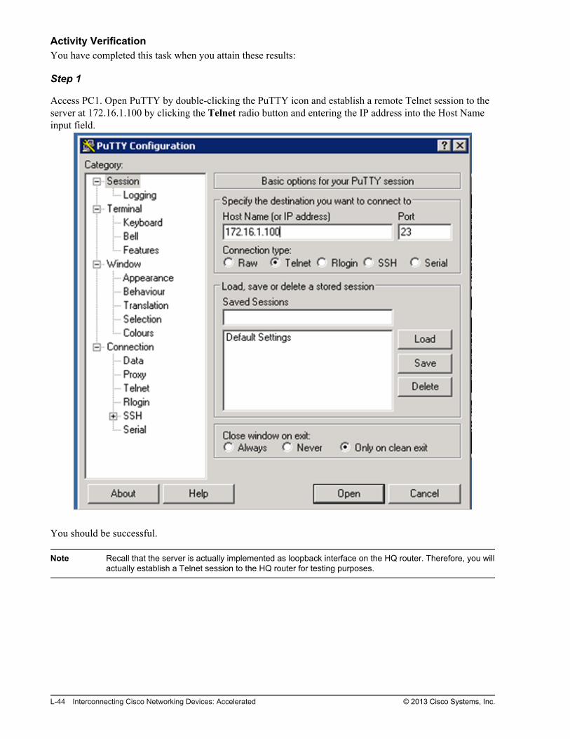
Access PC1. Open PuTTY by double-clicking the PuTTY icon and establish a remote Telnet session to theserver at 172.16.1.100 by clicking the Telnet radio button and entering the IP address into the Host Nameinput field.
You should be successful.
Note Recall that the server is actually implemented as loopback interface on the HQ router. Therefore, you willactually establish a Telnet session to the HQ router for testing purposes.
L-44 Interconnecting Cisco Networking Devices: Accelerated © 2013 Cisco Systems, Inc.

Step 2
Verify the user connection to the server using the show users command. This command will displaymanagement sessions to the router via console or via remote access.
HQ#show users Line User Host(s) Idle Location 0 con 0 idle 00:42:00*514 vty 0 idle 00:00:00 209.165.201.5
You should see that the Telnet session from PC1 is seen as originating from a translated IP address. Thetranslated IP address is the first free IP address from the NAT pool.
Note The session marked with an asterisk (*) is the one that is currently active and used.
© 2013 Cisco Systems, Inc. Lab Guide L-45

Step 3
Access PC2. Open PuTTY by double-clicking the PuTTY icon and establish a Telnet session to the serverat 172.16.1.100.
If PC2 is not configured with an IP address, assign it an IP address of 10.1.1.101/24.
You should be successful.
L-46 Interconnecting Cisco Networking Devices: Accelerated © 2013 Cisco Systems, Inc.

Step 4
Verify the user connection to the server using the show users command.
HQ#show users Line User Host(s) Idle Location 514 vty 0 idle 00:00:29 209.165.201.5*515 vty 1 idle 00:00:00 209.165.201.6
You should see that the Telnet session from PC2 is seen as originating from a translated IP address. Thetranslated IP address is the next free IP address from the NAT pool.
Step 5
Return to the Branch router. Verify that there are active NAT translations.
Branch#show ip nat translations Pro Inside global Inside local Outside local Outside globaltcp 209.165.201.5:1035 10.1.1.100:1035 172.16.1.100:23 172.16.1.100:23--- 209.165.201.5 10.1.1.100 --- ---tcp 209.165.201.6:1030 10.1.1.101:1030 172.16.1.100:23 172.16.1.100:23--- 209.165.201.6 10.1.1.101 --- ---
Notice that inside local IP addresses are translated into inside global IP addresses.
Step 6
Close the Telnet session on PC1 and PC2.
Task 4: Configure NAT with PATIn this task, you will configure dynamic NAT with PAT on the Branch router to translate the IP addressesof inside hosts to the public IP address of the Branch router. Then you will verify the NAT configurationand connectivity from PC1 and PC2 to the server.
Activity ProcedureComplete the following steps:
Step 1
Return to the Branch router.
Step 2
Remove the previously configured dynamic NAT rule.
© 2013 Cisco Systems, Inc. Lab Guide L-47

Step 3
Configure a dynamic source NAT/PAT (NAT with overload) rule that will translate inside hosts into the IPaddress of the router outside interface. Use the previously configured ACL to specify the hosts that areeligible for translations.
How many hosts that require NAT can you accommodate at the same time by overloading the IP address ofthe interface?
Step 4
Save the running configuration to the startup configuration.
Activity VerificationYou have completed this task when you attain these results:
L-48 Interconnecting Cisco Networking Devices: Accelerated © 2013 Cisco Systems, Inc.

Step 1
Access PC1. Open PuTTY by double-clicking the PuTTY icon and establish a Telnet session to the serverat 172.16.1.100.
You should be successful.
Step 2
Verify the user connection to the server using the show users command.
HQ#show users Line User Host(s) Idle Location*514 vty 0 idle 00:00:00 209.165.201.1
You should see that the Telnet session from PC1 is seen as originating from the IP address of the Branchrouter outside interface.
© 2013 Cisco Systems, Inc. Lab Guide L-49

Step 3
Access PC2. Open PuTTY by double-clicking the PuTTY icon and establish a Telnet session to the serverat 172.16.1.100.
You should be successful.
L-50 Interconnecting Cisco Networking Devices: Accelerated © 2013 Cisco Systems, Inc.

Step 4
Verify the user connection to the server using the show users command.
HQ#show users Line User Host(s) Idle Location 514 vty 0 idle 00:01:05 209.165.201.1*515 vty 1 idle 00:00:00 209.165.201.1
You should see that the Telnet session from PC2 is again seen as originating from the IP address of theBranch router outside interface.
Step 5
Return to the Branch router. Verify that there are active NAT translations.
Branch#show ip nat translations Pro Inside global Inside local Outside local Outside globaltcp 209.165.201.1:1042 10.1.1.100:1042 172.16.1.100:23 172.16.1.100:23tcp 209.165.201.1:1036 10.1.1.101:1036 172.16.1.100:23 172.16.1.100:23
Notice that two inside local IP addresses are translated into the same inside global IP address, which isconfigured on the Branch router outside interface. To provide two distinct translations, different sourceports are used.
Step 6
Close the Telnet session on PC1 and PC2.
© 2013 Cisco Systems, Inc. Lab Guide L-51

L-52 Interconnecting Cisco Networking Devices: Accelerated © 2013 Cisco Systems, Inc.

Lab 3-1: Enhancing theSecurity of the InitialConfiguration
Activity OverviewObjectivesSecuring administrative access to devices is crucial because you do not want unauthorized users to haveaccess to your network devices. In this lab, you will increase the security of the initial switch and routerconfiguration. After you have completed this activity, you will be able to meet these objectives:
Configure passwords on a router and switch
Configure and limit remote access to SSH
Configure an ACL to limit remote access
Configure the login banner

Visual ObjectiveThe figure illustrates what you will accomplish in this activity.
Visual Objective for Lab 3-1: Enhancing theSecurity of the Initial Configuration
© 2013 Cisco Systems, Inc.
Detailed Visual ObjectiveBranch
1WS1CP
• Add password protection
• Enable SSH
• Con!gure a login banner
• Add password protection
• Enable SSH
• Limit access with an ACL
• Con!gure a login banner
© 2013 Cisco Systems, Inc.
Required ResourcesThere are no additional resources that are required for this lab.
L-54 Interconnecting Cisco Networking Devices: Accelerated © 2013 Cisco Systems, Inc.
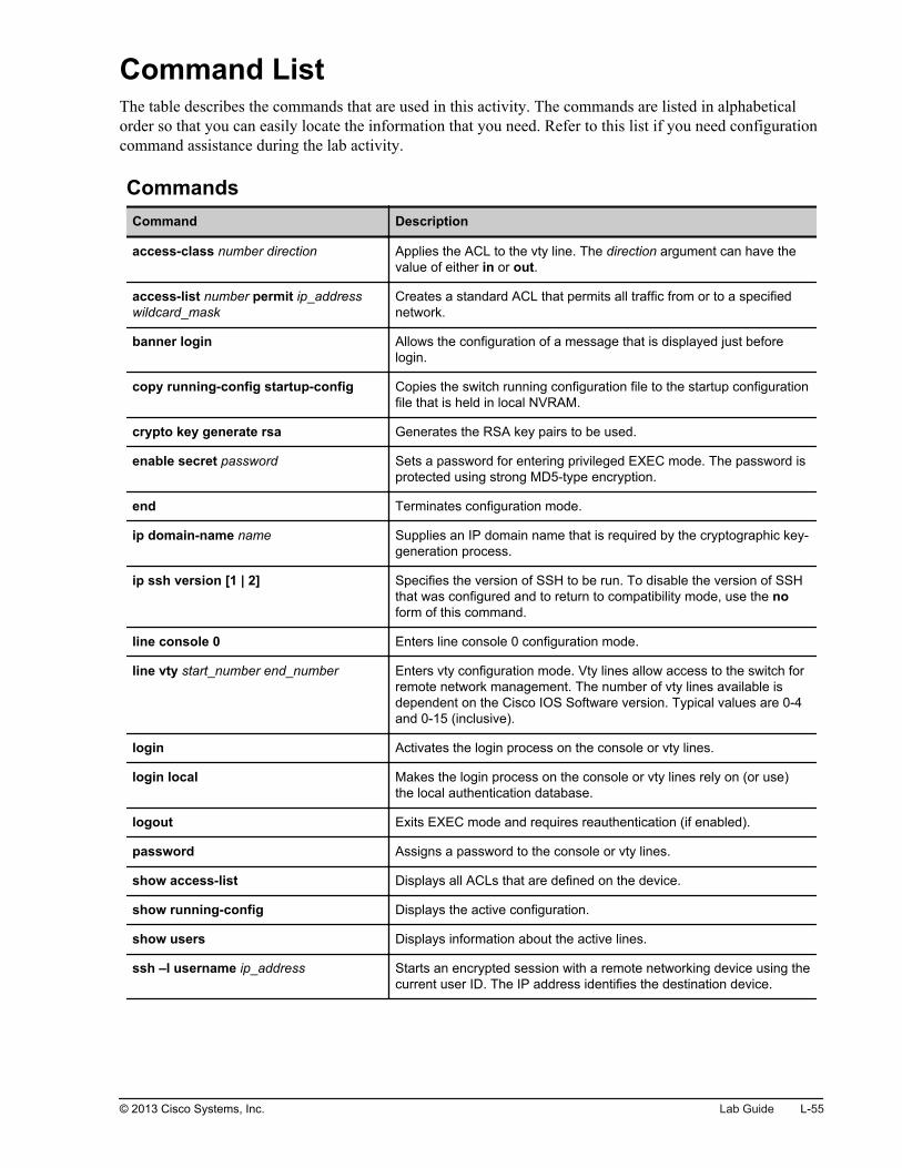
Command ListThe table describes the commands that are used in this activity. The commands are listed in alphabeticalorder so that you can easily locate the information that you need. Refer to this list if you need configurationcommand assistance during the lab activity.
CommandsCommand Description
access-class number direction Applies the ACL to the vty line. The direction argument can have thevalue of either in or out.
access-list number permit ip_addresswildcard_mask
Creates a standard ACL that permits all traffic from or to a specifiednetwork.
banner login Allows the configuration of a message that is displayed just beforelogin.
copy running-config startup-config Copies the switch running configuration file to the startup configurationfile that is held in local NVRAM.
crypto key generate rsa Generates the RSA key pairs to be used.
enable secret password Sets a password for entering privileged EXEC mode. The password isprotected using strong MD5-type encryption.
end Terminates configuration mode.
ip domain-name name Supplies an IP domain name that is required by the cryptographic key-generation process.
ip ssh version [1 | 2] Specifies the version of SSH to be run. To disable the version of SSHthat was configured and to return to compatibility mode, use the noform of this command.
line console 0 Enters line console 0 configuration mode.
line vty start_number end_number Enters vty configuration mode. Vty lines allow access to the switch forremote network management. The number of vty lines available isdependent on the Cisco IOS Software version. Typical values are 0-4and 0-15 (inclusive).
login Activates the login process on the console or vty lines.
login local Makes the login process on the console or vty lines rely on (or use)the local authentication database.
logout Exits EXEC mode and requires reauthentication (if enabled).
password Assigns a password to the console or vty lines.
show access-list Displays all ACLs that are defined on the device.
show running-config Displays the active configuration.
show users Displays information about the active lines.
ssh –l username ip_address Starts an encrypted session with a remote networking device using thecurrent user ID. The IP address identifies the destination device.
© 2013 Cisco Systems, Inc. Lab Guide L-55

Command Description
transport input [telnet | ssh | all] Specifies which protocols to use to connect to a specific line of thedevice.
username username secret password Creates a username and password pair that can then be used as alocal authentication database.
Job AidsThese job aids are available to help you complete the lab activity.
The table shows the hardware that is used in the lab and the operating system that is running on the devices.
Device Hardware Operating System
Branch Cisco 2901 Integrated Services Router c2900-universalk9-mz.SPA.152-4.M1
Headquarters
Cisco 2901 Integrated Services Router c2900-universalk9-mz.SPA.152-4.M1
SW1 Catalyst 2960 Series Switch c2960-lanbasek9-mz.150-1.SE3
PC1 Any PC Microsoft Windows 7
PC2 Any PC Microsoft Windows 7
There are no console or enable passwords that are set for the routers and switches in the initial lab setup.The table shows the username and password that are used to access PC1 and PC2.
Device Username Password
PC1 Administrator admin
PC2 Administrator admin
Topology and IP Addressing
Devices are connected with Ethernet links. The figure illustrates the interface identification and IPaddresses that are used in this lab setup.
L-56 Interconnecting Cisco Networking Devices: Accelerated © 2013 Cisco Systems, Inc.

Topology and IP Addressing
PC1 SW1
Branch
Fa0/1
Gi0/0
Fa0/13
10.1.1.100
10.1.1.11
VLAN 1: 10.1.1.1
© 2013 Cisco Systems, Inc.
The table shows the interface identification and IP addresses that are used in this lab setup.
Device Interface IP Address/Subnet Mask
Branch Gi0/1 209.165.201.1/27
Branch Gi0/0 10.1.1.1/24
Headquarters Gi0/1 209.165.201.2/27
Headquarters Loopback0 172.16.1.100/24
SW1 VLAN1 10.1.1.11/24
PC1 Ethernet adapter local area connection 10.1.1.100/24
PC2 Ethernet adapter local area connection 10.1.1.101/24
Task 1: Add Password ProtectionFollowing the initial configuration of the switch, where passwords have been configured for the vty lines,two potential security holes exist. First, a security breach is possible when the vty lines have the loginprocess deactivated and the password is too simple. Second, security can be breached because the consoleport initially is not protected by a password at all. In this task, you will secure console access and access toprivileged EXEC mode on a router and a switch.
Activity ProcedureComplete the following steps:
Step 1
Access the Branch router.
© 2013 Cisco Systems, Inc. Lab Guide L-57

Step 2
Secure the console line with the password cisco.
Step 3
Exit to the console login screen by issuing the end and exit commands.
You will be asked for the password that you configured in the previous step.
Branch(config-line)# endBranch# exitBranch con0 is now availablePress RETURN to get started.User Access VerificationPassword:Branch>
Step 4
Examine the running configuration and identify the password that was configured for the console line. Notethat the password is in cleartext.
Branch# show running-config | section line conline con 0 exec-timeout 60 0 password cisco logging synchronous login
Step 5
Create the username ccna and assign the secret password cisco to it. Look at the Command List section toidentify the correct command.
Then change the mode of authentication on the console line so that this user is authenticated using thisusername and password.
L-58 Interconnecting Cisco Networking Devices: Accelerated © 2013 Cisco Systems, Inc.

Step 6
Exit to the console login screen by issuing the end and exit commands.
You will be asked for a username and password. Enter the credentials that you created in the previous step.
Branch(config-line)# endBranch# exitBranch con0 is now availablePress RETURN to get started.User Access VerificationUsername: ccnaPassword:Branch>
Step 7
Examine the running configuration and identify the username and password that you created.
Note that the password is encrypted, not in cleartext. You could use the service password-encryptioncommand to encode the cleartext password, but this encryption type is weak.
Branch# show running-config | section usernameusername ccna secret 4 tnhtc92DXBhelxjYk8LWJrPV36S2i4ntXrpb4RFmfqY
Step 8
Secure vty lines 0 through 15. Users should be able to log in using the username ccna and password ciscothat you previously defined.
For security reasons, the passwords for console and vty access should be different. Also, in productionenvironments, you should use strong passwords (at least eight characters and a combination of letters,numbers, and special characters). In the lab environment, we are using the same passwords for console andvty access.
© 2013 Cisco Systems, Inc. Lab Guide L-59

Step 9
On PC1, open PuTTY and establish a Telnet session to the Branch router to verify that you configured vtysecurity correctly.
Enter the appropriate credentials to log into the Branch router.
L-60 Interconnecting Cisco Networking Devices: Accelerated © 2013 Cisco Systems, Inc.

Step 10
On the Branch router, secure access to privileged EXEC mode with the password cisco. The password mustbe encrypted with strong encryption.
Step 11
Save the changes that you made on the Branch router.
Step 12
Exit privileged EXEC mode and then re-enter it. When prompted, enter the password that you configured inthe previous step.
Branch# disableBranch> enablePassword:Branch#
Step 13
Examine the running configuration of the Branch router and identify the line where the password thatallows access to privileged EXEC mode is configured. Notice that the password is encrypted.
Branch# show running-config | section enableenable secret 4 tnhtc92DXBhelxjYk8LWJrPV36S2i4ntXrpb4RFmfqY
© 2013 Cisco Systems, Inc. Lab Guide L-61

Step 14
Access switch SW1. Configure it with the enable secret password cisco. Users should be able to log into theconsole and vty lines by using the username ccna and the password cisco. Use strong encryption.
Step 15
Save the changes that you made on the SW1 switch.
Step 16
On the SW switch, go to the user EXEC mode by entering the end and exit commands. Log into the switchSW console by using the previously configured username and password in order to verify consoleprotection.
SW1(config-line)# endSW1# exitSW1 con0 is now availablePress RETURN to get started.User Access VerificationUsername: ccnaPassword: SW1>
Step 17
On the SW switch, enter the privileged EXEC mode by entering the previously configured password.
SW1> enablePassword: SW1#
L-62 Interconnecting Cisco Networking Devices: Accelerated © 2013 Cisco Systems, Inc.

Step 18
Return to PC1, open PuTTY, and establish a Telnet session to the SW1 switch to verify that you configuredvty security correctly.
Enter the appropriate credentials to log into the switch.
© 2013 Cisco Systems, Inc. Lab Guide L-63
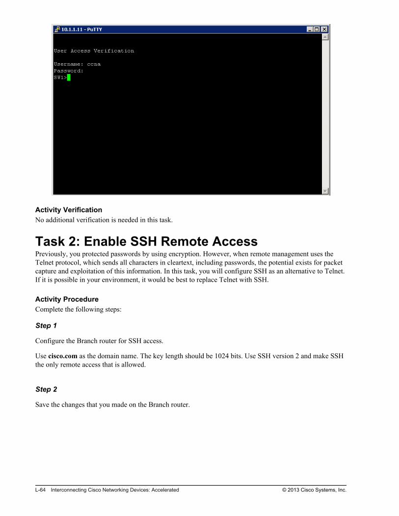
Activity VerificationNo additional verification is needed in this task.
Task 2: Enable SSH Remote AccessPreviously, you protected passwords by using encryption. However, when remote management uses theTelnet protocol, which sends all characters in cleartext, including passwords, the potential exists for packetcapture and exploitation of this information. In this task, you will configure SSH as an alternative to Telnet.If it is possible in your environment, it would be best to replace Telnet with SSH.
Activity ProcedureComplete the following steps:
Step 1
Configure the Branch router for SSH access.
Use cisco.com as the domain name. The key length should be 1024 bits. Use SSH version 2 and make SSHthe only remote access that is allowed.
Step 2
Save the changes that you made on the Branch router.
L-64 Interconnecting Cisco Networking Devices: Accelerated © 2013 Cisco Systems, Inc.

Step 3
Configure the SW1 switch for SSH access.
Use cisco.com as the domain name, specify a key length of 1024 bits, use SSH version 2, and make SSHthe only remote access that is allowed.
Step 4
Save the changes that you made on the SW1 switch.
Step 5
On PC1, open PuTTY and try to connect to the Branch router using Telnet. Your attempt will beunsuccessful.
© 2013 Cisco Systems, Inc. Lab Guide L-65

Step 6
Now try to remotely connect from PC1 to the Branch router using SSH. Your attempt should be successful.
Leave the connection open for the next step.
L-66 Interconnecting Cisco Networking Devices: Accelerated © 2013 Cisco Systems, Inc.

Step 7
On the Branch router, show the users that are logged into the system. Identify the user that is using the vtyline.
Branch# show users Line User Host(s) Idle Location* 0 con 0 ccna idle 00:00:00 514 vty 0 ccna idle 00:00:27 10.1.1.100 Interface User Mode Idle Peer Address
© 2013 Cisco Systems, Inc. Lab Guide L-67

Step 8
Return to PC1. Open another PuTTY and apply SSH to the SW1 switch in order to verify the SSHconfiguration on the switch. Your attempt should be successful.
L-68 Interconnecting Cisco Networking Devices: Accelerated © 2013 Cisco Systems, Inc.

Activity VerificationNo additional verification is needed in this task.
Task 3: Limit Remote Access to Selected NetworkAddressesIn this task, you will create an ACL on the SW1 switch and apply it to the vty lines. The ACL will permitremote sessions from the Branch router but not from PC1.
Activity ProcedureComplete the following steps:
Step 1
On the SW1 switch, define a standard ACL that will permit only the IP address of the Branch router.
Any attempts to establish remote sessions from unauthorized devices should be logged.
Step 2
Apply the defined ACL to all vty lines of the SW1 switch.
SW1(config)# line vty 0 15SW1(config-line)# access-class 1 in
Step 3
Save the changes that you made on the SW1 switch.
© 2013 Cisco Systems, Inc. Lab Guide L-69

Activity VerificationYou have completed this task when you attain this result:
Step 1
Try to establish an SSH remote session from PC1 to SW1 at 10.1.1.11.
You should not be successful because the ACL that you defined allows only the Branch router to establishsessions to the SW1 switch.
Step 2
Try to establish an SSH remote session from the Branch router.
You should be successful.
Branch# ssh -l ccna 10.1.1.11Password:SW1>
L-70 Interconnecting Cisco Networking Devices: Accelerated © 2013 Cisco Systems, Inc.
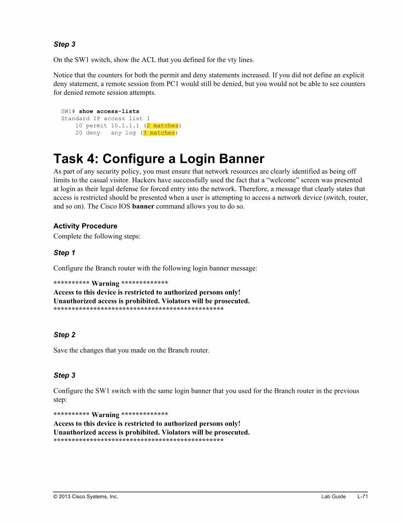
Step 3
On the SW1 switch, show the ACL that you defined for the vty lines.
Notice that the counters for both the permit and deny statements increased. If you did not define an explicitdeny statement, a remote session from PC1 would still be denied, but you would not be able to see countersfor denied remote session attempts.
SW1# show access-listsStandard IP access list 1 10 permit 10.1.1.1 (2 matches) 20 deny any log (3 matches)
Task 4: Configure a Login BannerAs part of any security policy, you must ensure that network resources are clearly identified as being offlimits to the casual visitor. Hackers have successfully used the fact that a “welcome” screen was presentedat login as their legal defense for forced entry into the network. Therefore, a message that clearly states thataccess is restricted should be presented when a user is attempting to access a network device (switch, router,and so on). The Cisco IOS banner command allows you to do so.
Activity ProcedureComplete the following steps:
Step 1
Configure the Branch router with the following login banner message:
********** Warning *************Access to this device is restricted to authorized persons only!Unauthorized access is prohibited. Violators will be prosecuted.***********************************************
Step 2
Save the changes that you made on the Branch router.
Step 3
Configure the SW1 switch with the same login banner that you used for the Branch router in the previousstep:
********** Warning *************Access to this device is restricted to authorized persons only!Unauthorized access is prohibited. Violators will be prosecuted.***********************************************
© 2013 Cisco Systems, Inc. Lab Guide L-71

Step 4
Save the changes that you made on the SW1 switch.
Activity VerificationYou have completed this task when you attain these results:
Step 1
Access the Branch router. Log out of the Branch router and then log back in.
Notice the login banner that you were presented with as you logged in.
Branch# logoutBranch con0 is now availablePress RETURN to get started.********** Warning *************Access to this device is restricted to authorized persons only!Unauthorized access is prohibited. Violators will be prosecuted.***********************************************User Access VerificationUsername: ccnaPassword:
Step 2
Access SW1. Log out of the SW1 switch console and then log back in.
Notice the login banner that you were presented with as you logged in.
SW1# logoutSW1 con0 is now availablePress RETURN to get started.********** Warning *************Access to this device is restricted to authorized persons only!Un-authorized access is prohibited. Violators will be prosecuted.***********************************************User Access VerificationUsername: ccnaPassword:
Note When accessing network devices via the SSH protocol, some terminal clients such as PuTTY display thelogin banner only after the username parameter is entered as input.
L-72 Interconnecting Cisco Networking Devices: Accelerated © 2013 Cisco Systems, Inc.

Lab 3-2: Device Hardening
Activity OverviewObjectivesDevice hardening is crucial to increasing security in the network. In this lab, you will perform securitydevice hardening on a router and switch. After you have completed this activity, you will be able to meetthese objectives:
Disable unused ports
Configure port security on a switch
Disable unused services
Configure NTP

Visual ObjectiveThe figure illustrates what you will accomplish in this activity.
Visual Objective for Lab 3-2: Device Hardening
© 2013 Cisco Systems, Inc.
Detailed Visual Objective
• Disable unused ports
• Configure port security
• Disable Cisco Discovery Protocol
• Configure NTP client
Internet Server
PC1 SW1
QHhcnarB
Configure NTP
client and server
Inside
Outside
NTP server
© 2013 Cisco Systems, Inc.
Required ResourcesNo additional resources are required for this lab.
L-74 Interconnecting Cisco Networking Devices: Accelerated © 2013 Cisco Systems, Inc.

Command ListThe table that follows describes the commands that are used in this activity. The commands are listed inalphabetical order so that you can easily locate the information that you need. Refer to this list if you needconfiguration command assistance during the lab activity.
CommandsCommand Description
[no] cdp enable Enables or disables Cisco Discovery Protocol on an interface
configure terminal Enters configuration mode
interface interface Enters interface configuration mode
ntp master [stratum] Configures Cisco IOS Software as an NTP master clock.
ntp server {ip-address} Allows the software clock to be synchronized by an NTP time server
ping dest_IP Verifies connectivity between the source IP and destination IP
show cdp neighbors Displays detailed information about neighboring devices that arediscovered by using Cisco Discovery Protocol
show interfaces Displays statistics for all interfaces that are configured on the router
show interfaces status Displays the status of interfaces
show port-security interface interface Displays the port security settings that are defined for an interface
show ntp associations Displays the status of NTP associations
show ntp status Displays the status of NTP
show port-security address Displays the secure MAC addresses for all ports
[no] shutdown Enables or disables an interface on the router
switchport mode access Configures a switchport as an access port
switchport port-security Enables the port security feature on the interface
switchport port-security mac-addressmac-address
Enters a secure MAC address for the interface
Job AidsThese job aids are available to help you complete the lab activity.
The table shows the hardware that is used in the lab and the operating system that is running on the devices.
Device Hardware Operating System
Branch Cisco 2901 Integrated Services Router c2900-universalk9-mz.SPA.152-4.M1
Headquarters
Cisco 2901 Integrated Services Router c2900-universalk9-mz.SPA.152-4.M1
SW1 Catalyst 2960 Series Switch c2960-lanbasek9-mz.150-1.SE3
© 2013 Cisco Systems, Inc. Lab Guide L-75

Device Hardware Operating System
PC1 Any PC Microsoft Windows 7
PC2 Any PC Microsoft Windows 7
The table shows usernames and passwords that are used to access the lab devices.
Device Username Password
PC1 Administrator admin
PC2 Administrator admin
Branch (console access) ccna cisco
Branch (enable password) / cisco
SW1 (console access) ccna cisco
SW1 (enable password) / cisco
Topology and IP Addressing
Devices are connected with Ethernet links. The figure illustrates the interface identification and IPaddresses that are used in this lab setup.
Topology and IP Addressing
InternetServer
PC1
PC2
SW1
Branch
HQ
Fa0/1
Gi0/0
Fa0/13
Fa0/3
Gi0/1
209.165.201.1
Gi0/1
209.165.201.2
10.1.1.100
10.1.1.101
10.1.1.11
VLAN 1: 10.1.1.1 172.16.1.100
0/3
© 2013 Cisco Systems, Inc.
The table shows the interface identification and IP addresses that are used in this lab setup.
Device Interface IP Address/Subnet Mask
Branch Gi0/1 209.165.201.1/27
Branch Gi0/0 10.1.1.1/24
Headquarters Gi0/1 209.165.201.2/27
L-76 Interconnecting Cisco Networking Devices: Accelerated © 2013 Cisco Systems, Inc.

Device Interface IP Address/Subnet Mask
Headquarters Loopback0 172.16.1.100/24
SW1 VLAN1 10.1.1.11/24
PC1 Ethernet adapter local area connection 10.1.1.100/24
PC2 Ethernet adapter local area connection 10.1.1.101/24
Task 1: Disable Unused PortsUnused ports on a switch can be a security risk. A hacker can plug a switch into an unused port and becomepart of the network. In this task, you will disable unused ports on a network switch.
Activity ProcedureComplete the following steps:
Step 1
Access the SW1 switch.
Step 2
Disable unused interfaces FastEthernet 0/14 to FastEthernet 0/24 with as few configuration steps aspossible.
Step 3
Examine the status of interfaces FastEthernet 0/14 to FastEthernet 0/24.
You should see interfaces FastEthernet 0/14 to FastEthernet 0/24 as disabled.
SW1# show interfaces statusPort Name Status Vlan Duplex Speed Type<output omitted>Fa0/13 connected 1 a-full a-100 10/100BaseTXFa0/14 disabled 1 auto auto 10/100BaseTXFa0/15 disabled 1 auto auto 10/100BaseTXFa0/16 disabled 1 auto auto 10/100BaseTXFa0/17 disabled 1 auto auto 10/100BaseTXFa0/18 disabled 1 auto auto 10/100BaseTXFa0/19 disabled 1 auto auto 10/100BaseTXFa0/20 disabled 1 auto auto 10/100BaseTXFa0/21 disabled 1 auto auto 10/100BaseTXFa0/22 disabled 1 auto auto 10/100BaseTXFa0/23 disabled 1 auto auto 10/100BaseTXFa0/24 disabled 1 auto auto 10/100BaseTX
Step 4
Save the running configuration to the startup configuration.
© 2013 Cisco Systems, Inc. Lab Guide L-77

Activity VerificationNo additional verification is needed in this task.
Task 2: Configure Port Security on a SwitchPort security is a feature that is supported on Cisco Catalyst switches that restricts a switch port to a specificset or number of MAC addresses. In this task, you will configure port security on the switch interface thatfaces the router. You will also demonstrate a port security violation.
Activity ProcedureComplete the following steps:
Step 1
Access the Branch router.
Step 2
Examine the MAC address of the Branch router interface GigabitEthernet 0/0, which faces the SW1 switch.
Write down the MAC address, which you will need to configure the port security feature.
Branch# show interfaces GigabitEthernet 0/0GigabitEthernet0/0 is up, line protocol is up Hardware is CN Gigabit Ethernet, address is f866.f231.7250 (bia f866.f231.7250)
Note Your MAC address might be different from the the address that is shown in the output.
Step 3
Access the SW1 switch.
Step 4
Configure interface FastEthernet0/13, which faces the Branch router, as a static access port.
Step 5
Enable the port security feature on interface FastEthernet0/13. Manually specify the secure MAC addressf866.f231.7251 (which is not the MAC address of the Branch router).
You will simulate a port security violation by misconfiguring the secure MAC address.
L-78 Interconnecting Cisco Networking Devices: Accelerated © 2013 Cisco Systems, Inc.

Step 6
Observe the switch output and verify the status of SW1 interface FastEthernet0/13. Make sure that a portsecurity violation occurred because of the misconfigured secure MAC address.
Sep 28 11:16:18.312: %PM-4-ERR_DISABLE: psecure-violation error detected on Fa0/13, putting Fa0/13 in err-disable stateSep 28 11:16:18.312: %PORT_SECURITY-2-PSECURE_VIOLATION: Security violation occurred, caused by MAC address f866.f231.7250 on port FastEthernet0/13.Sep 28 11:16:19.318: %LINEPROTO-5-UPDOWN: Line protocol on Interface FastEthernet0/13, changed state to downSep 28 11:16:20.317: %LINK-3-UPDOWN: Interface FastEthernet0/13, changed state to downSW1# show interfaces FastEthernet 0/13FastEthernet0/13 is down, line protocol is down (err-disabled) Hardware is Fast Ethernet, address is 001e.147c.6f0d (bia 001e.147c.6f0d)SW1#show port-security interface FastEthernet 0/13Port Security : EnabledPort Status : Secure-shutdownViolation Mode : ShutdownAging Time : 0 minsAging Type : AbsoluteSecureStatic Address Aging : DisabledMaximum MAC Addresses : 1Total MAC Addresses : 1Configured MAC Addresses : 1Sticky MAC Addresses : 0Last Source Address:Vlan : f866.f231.7250:1Security Violation Count : 1
A port security violation occurs due to management traffic (Cisco Discovery Protocol, for example) comingfrom the router toward the switch.
Step 7
Try to ping PC1 at 10.1.1.100 from the Branch router. Your attempt should fail because the switch portconnecting to the Branch router is error-disabled.
Branch# ping 10.1.1.100Type escape sequence to abort.Sending 5, 100-byte ICMP Echos to 10.1.1.100, timeout is 2 seconds:U.U.USuccess rate is 0 percent (0/5)
Step 8
Change the port security of the secure MAC address on SW1 interface FastEthernet0/13 to the correct MACaddress, which you wrote down.
Note Your MAC address for the Branch router might be different from the address that was shown in theoutput.
© 2013 Cisco Systems, Inc. Lab Guide L-79

Step 9
Make the FastEthernet0/13 interface on SW1 operational again.
Step 10
Observe the switch output. Verify the status of the FastEthernet0/13 interface on SW1 and make sure thatthe interface is operational again.
Sep 28 11:10:07.080: %LINK-3-UPDOWN: Interface FastEthernet0/13, changed state to upSep 28 11:10:08.087: %LINEPROTO-5-UPDOWN: Line protocol on Interface FastEthernet0/13, changed state to upSW1# show interfaces FastEthernet 0/13FastEthernet0/13 is down, line protocol is up Hardware is Fast Ethernet, address is 001e.147c.6f0d (bia 001e.147c.6f0d)
Step 11
Try to ping PC1 at 10.1.1.100 from the Branch router. Your attempt should succeed now.
Branch# ping 10.1.1.100Type escape sequence to abort.Sending 5, 100-byte ICMP Echos to 10.1.1.100, timeout is 2 seconds:!!!!!
Step 12
Display the secure MAC addresses for interface FastEthernet0/13.
SW1# show port-security address Secure Mac Address Table--------------------------------------------------------------------------Vlan Mac Address Type Ports Remaining Age (mins)---- ----------- ---- ----- ------------- 1 f866.f231.7250 SecureConfigured Fa0/13 ---------------------------------------------------------------------------Total Addresses in System (excluding one mac per port) : 1Max Addresses limit in System (excluding one mac per port) : 8192
L-80 Interconnecting Cisco Networking Devices: Accelerated © 2013 Cisco Systems, Inc.

Step 13
Display the port security settings for the SW1 switch.
SW1# show port-securitySecure Port MaxSecureAddr CurrentAddr SecurityViolation Security Action (Count) (Count) (Count)--------------------------------------------------------------------------- Fa0/13 1 1 0 Shutdown---------------------------------------------------------------------------Total Addresses in System (excluding one mac per port) : 1Max Addresses limit in System (excluding one mac per port) : 8192
Step 14
Disable the port security feature on interface FastEthernet 0/13.
Step 15
Save the running configuration to the startup configuration.
Activity VerificationNo additional verification is needed in this task.
Task 3: Disable Unused ServicesSome services may not be needed on the router and therefore can be disabled. You will disable CiscoDiscovery Protocol on the switch interface toward the router.
Activity ProcedureComplete the following steps:
Step 1
Access the Branch router.
Step 2
Examine the neighbor devices of the Branch router.
You should see the SW1 switch as the neighbor device.
Branch# show cdp neighborsCapability Codes: R - Router, T - Trans Bridge, B - Source Route Bridge S - Switch, H - Host, I - IGMP, r - Repeater, P - Phone, D - Remote, C - CVTA, M - Two-port Mac RelayDevice ID Local Intrfce Holdtme Capability Platform Port IDSW1 Gig 0/0 135 S I WS-C2960- Fas 0/13
© 2013 Cisco Systems, Inc. Lab Guide L-81

Step 3
Disable Cisco Discovery Protocol on the SW1 interface that is facing the Branch router.
Step 4
Examine the neighbor devices of the Branch router.
You should not see switch SW1 anymore as a neighbor device because you disabled Cisco DiscoveryProtocol on the switch interface toward the router.
Branch# show cdp neighborsCapability Codes: R - Router, T - Trans Bridge, B - Source Route Bridge S - Switch, H - Host, I - IGMP, r - Repeater, P - Phone, D - Remote, C - CVTA, M - Two-port Mac RelayDevice ID Local Intrfce Holdtme Capability Platform Port ID
Note It may take up to 3 minutes for the neighbor to disappear from the output because of the holddown timerthat is set to 180 seconds.
Step 5
Examine the neighbor devices of the SW1 switch.
You should see no neighbor device because you disabled Cisco Discovery Protocol on the switch interfacetoward the Branch router.
SW1# show cdp neighborsCapability Codes: R - Router, T - Trans Bridge, B - Source Route Bridge S - Switch, H - Host, I - IGMP, r - Repeater, P - Phone, D - Remote, C - CVTA, M - Two-port Mac RelayDevice ID Local Intrfce Holdtme Capability Platform Port ID
Step 6
Enable Cisco Discovery Protocol on the SW1 interface that faces the Branch router.
Step 7
Save the running configuration to the startup configuration.
Activity VerificationNo additional verification is needed in this task.
L-82 Interconnecting Cisco Networking Devices: Accelerated © 2013 Cisco Systems, Inc.

Task 4: Configure NTPNetworks use NTP to synchronize the clocks of various devices across a network. Clock synchronizationwithin a network is critical for digital certificates and for correct interpretation of events within syslog data.In this task, you will configure the Branch router as an NTP client of the server. The Branch router will alsoact as an NTP server for SW1 at the same time. The server has been preconfigured as the NTP server withstratum 3.
Activity ProcedureComplete the following steps:
Step 1
Configure the Branch router as an NTP client of the server at 172.16.1.100.
Step 2
Verify NTP associations on the Branch router.
Branch# show ntp associations address ref clock st when poll reach delay offset disp*~172.16.1.100 127.127.1.1 3 58 128 77 1.067 36.634 0.968 * sys.peer, # selected, + candidate, - outlyer, x falseticker, ~ configured
You should see that the Branch router synchronized its clock with the server.
Note It may take several minutes in order to synchronize the clock with the NTP server.
Step 3
Verify the NTP status on the Branch router.
Branch# show ntp status Clock is synchronized, stratum 4, reference is 172.16.1.100 nominal freq is 250.0000 Hz, actual freq is 249.9989 Hz, precision is 2**21ntp uptime is 139700 (1/100 of seconds), resolution is 4016reference time is D46AE7E9.B6A4139E (09:46:17.713 UTC Thu Dec 6 2012)clock offset is 35.7065 msec, root delay is 0.87 msecroot dispersion is 40.23 msec, peer dispersion is 1.88 msecloopfilter state is 'CTRL' (Normal Controlled Loop), drift is 0.000004366 s/ssystem poll interval is 128, last update was 121 sec ago.
What is the stratum of the clock on the Branch router?
Step 4
Access the SW1 switch.
© 2013 Cisco Systems, Inc. Lab Guide L-83

Step 5
Configure SW1 as an NTP client that will synchronize its time with the Branch router. Although the Branchrouter is configured only with NTP client configuration, it will respond to time requests from other clients.It will act as a server for switch SW1.
Step 6
Verify the NTP status and the NTP association status on the SW1 switch.
SW1# show ntp status Clock is synchronized, stratum 5, reference is 10.1.1.1 nominal freq is 119.2092 Hz, actual freq is 119.2091 Hz, precision is 2**17reference time is D46AEB16.D3639982 (09:59:50.825 UTC Thu Dec 6 2012)clock offset is 58.8216 msec, root delay is 2.30 msecroot dispersion is 122.31 msec, peer dispersion is 8.38 msecloopfilter state is 'CTRL' (Normal Controlled Loop), drift is 0.000001118 s/ssystem poll interval is 128, last update was 862 sec ago.SW1# show ntp associations address ref clock st when poll reach delay offset disp*~10.1.1.1 172.16.1.100 4 115 128 377 1.436 58.821 8.389 * sys.peer, # selected, + candidate, - outlyer, x falseticker, ~ configured
You should see that SW1 synchronized its clock with the Branch router.
What is the stratum of the clock on the SW1 switch?
Note It may take several minutes in order to synchronize the clock with the NTP server.
Step 7
Save the running configuration to the startup configuration.
Activity VerificationNo additional verification is needed in this task.
L-84 Interconnecting Cisco Networking Devices: Accelerated © 2013 Cisco Systems, Inc.

Lab 3-3: Filtering Traffic withACLs
Activity OverviewObjectivesA common mechanism for filtering traffic is ACLs, which enable you to allow, limit, or restrict access to anetwork resource. In this lab, you will configure traffic filtering using ACLs. After you have completed thisactivity, you will be able to meet these objectives:
Configure extended, named ACLs
Troubleshoot ACLs

Visual ObjectiveThe figure illustrates what you will accomplish in this activity.
Visual Objective for Lab 3-3: Filtering Trafficwith ACLs
Server
PC1
PC2
SW1
SW2
Branch
HQ
© 2013 Cisco Systems, Inc.
Detailed Visual Objective
Internet
Server
PC1
PC2
SW1
QHhcnarBConfigure ACL
Troubleshoot ACL
Telnet Allowed
Telnet Blocked
All Other Traffic Allowed
All Other Traffic Allowed
© 2013 Cisco Systems, Inc.
Required ResourcesThere are no additional required resources for this lab.
L-86 Interconnecting Cisco Networking Devices: Accelerated © 2013 Cisco Systems, Inc.
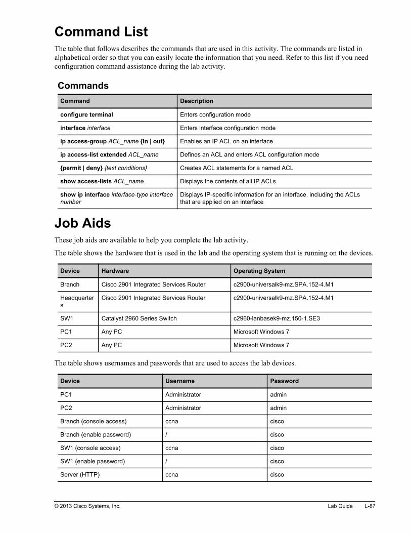
Command ListThe table that follows describes the commands that are used in this activity. The commands are listed inalphabetical order so that you can easily locate the information that you need. Refer to this list if you needconfiguration command assistance during the lab activity.
CommandsCommand Description
configure terminal Enters configuration mode
interface interface Enters interface configuration mode
ip access-group ACL_name {in | out} Enables an IP ACL on an interface
ip access-list extended ACL_name Defines an ACL and enters ACL configuration mode
{permit | deny} {test conditions} Creates ACL statements for a named ACL
show access-lists ACL_name Displays the contents of all IP ACLs
show ip interface interface-type interfacenumber
Displays IP-specific information for an interface, including the ACLsthat are applied on an interface
Job AidsThese job aids are available to help you complete the lab activity.
The table shows the hardware that is used in the lab and the operating system that is running on the devices.
Device Hardware Operating System
Branch Cisco 2901 Integrated Services Router c2900-universalk9-mz.SPA.152-4.M1
Headquarters
Cisco 2901 Integrated Services Router c2900-universalk9-mz.SPA.152-4.M1
SW1 Catalyst 2960 Series Switch c2960-lanbasek9-mz.150-1.SE3
PC1 Any PC Microsoft Windows 7
PC2 Any PC Microsoft Windows 7
The table shows usernames and passwords that are used to access the lab devices.
Device Username Password
PC1 Administrator admin
PC2 Administrator admin
Branch (console access) ccna cisco
Branch (enable password) / cisco
SW1 (console access) ccna cisco
SW1 (enable password) / cisco
Server (HTTP) ccna cisco
© 2013 Cisco Systems, Inc. Lab Guide L-87

Topology and IP Addressing
Devices are connected with Ethernet links. The figure illustrates the interface identification and IPaddresses that are used in this lab setup.
Topology and IP Addressing
InternetServer
PC1
PC2
SW1
Branch
HQ
Fa0/1
Gi0/0
Fa0/13
Fa0/3
Gi0/1
209.165.201.1
Gi0/1
209.165.201.2
10.1.1.100
10.1.1.101
10.1.1.11
VLAN 1: 10.1.1.1 172.16.1.100
0/3
© 2013 Cisco Systems, Inc.
The table shows the interface identification and IP addresses that are used in this lab setup.
Device Interface IP Address/Subnet Mask
Branch Gi0/1 209.165.201.1/27
Branch Gi0/0 10.1.1.1/24
Headquarters Gi0/1 209.165.201.2/27
Headquarters Loopback0 172.16.1.100/24
SW1 VLAN1 10.1.1.11/24
PC1 Ethernet adapter local area connection 10.1.1.100/24
PC2 Ethernet adapter local area connection 10.1.1.101/24
Task 1: Configure an ACLACLs enable you to control access to network resources based on Layer 3 packet-header information. Inthis task, you will configure an ACL that will prevent a Telnet connection from PC2 to the server. All otherIP traffic will be permitted.
Activity ProcedureComplete the following steps:
L-88 Interconnecting Cisco Networking Devices: Accelerated © 2013 Cisco Systems, Inc.

Step 1
Access the Branch router. Use the credentials provided in the Job Aids section of the document in order tolog in.
Step 2
Configure an extended ACL named Telnet that will prevent a Telnet connection from PC2 to the server. Allother IP traffic should be permitted.
Step 3
Verify the content of the configured ACL.
Branch# show access-lists TelnetExtended IP access list Telnet 10 deny tcp host 10.1.1.101 host 172.16.1.100 eq telnet 20 permit ip any any
Step 4
Apply the configured ACL to the GigabitEthernet0/0 interface in the correct direction.
Step 5
Verify that the configured interface is applied to the GigabitEthernet0/0 interface in the correct direction.
Branch# show ip interface GigabitEthernet 0/0GigabitEthernet0/0 is up, line protocol is up Internet address is 10.1.1.1/24 Broadcast address is 255.255.255.255 Address determined by setup command MTU is 1500 bytes Helper address is not set Directed broadcast forwarding is disabled Outgoing access list is not set Inbound access list is Telnet Proxy ARP is enabled Local Proxy ARP is disabled <...output omitted...>
Step 6
Save the running configuration to the startup configuration.
© 2013 Cisco Systems, Inc. Lab Guide L-89

Step 7
Access PC1. Open PuTTY by double-clicking the PuTTY icon and establish a Telnet session to the serverat 172.16.1.100.
L-90 Interconnecting Cisco Networking Devices: Accelerated © 2013 Cisco Systems, Inc.

You should be successful.
Step 8
Verify that the counter that was matched by the permit ACL statement increased.
Branch# show access-lists TelnetExtended IP access list Telnet 10 deny tcp host 10.1.1.101 host 172.16.1.100 eq telnet 20 permit ip any any (10 matches)
Note The actual number of ACL hits may differ from the outputs that are provided in the lab guide.
© 2013 Cisco Systems, Inc. Lab Guide L-91

Step 9
Access PC2. Open PuTTY by double-clicking the PuTTY icon and establish a Telnet session to the serverat 172.16.1.100.
L-92 Interconnecting Cisco Networking Devices: Accelerated © 2013 Cisco Systems, Inc.

You should not be successful because the configured ACL blocks Telnet traffic from PC2 to the server.
Step 10
Verify that the counter that was matched by the deny ACL statement increased.
Branch#show access-lists TelnetExtended IP access list Telnet 10 deny tcp host 10.1.1.101 host 172.16.1.100 eq telnet (9 matches) 20 permit ip any any (10 matches)
© 2013 Cisco Systems, Inc. Lab Guide L-93

Step 11
Access PC1. Open Internet Explorer and try to reach the HTTP server at IP address 172.16.1.100. Use thecredentials that are provided in the Job Aids section of the document in order to log in.
You should be successful.
L-94 Interconnecting Cisco Networking Devices: Accelerated © 2013 Cisco Systems, Inc.

Step 12
Access PC2. Open Internet Explorer and try to reach the HTTP server at IP address 172.16.1.100. Use thecredentials that are provided in the Job Aids section of the document in order to log in.
You should be successful.
Step 13
Verify that the counter that was matched by the permit ACL statement increased.
Branch# show access-lists TelnetExtended IP access list Telnet 10 deny tcp host 10.1.1.101 host 172.16.1.100 eq telnet (9 matches) 20 permit ip any any (274 matches)
Activity VerificationNo additional verification is needed in this task.
Task 2: Lab SetupIn this lab setup procedure, you will load a configuration to the Branch router to create a trouble ticket. Youwill resolve this ticket in the next task.
© 2013 Cisco Systems, Inc. Lab Guide L-95

Activity ProcedureComplete the following steps:
Step 1
Access the Branch router.
Step 2
Copy the TSHOOT_Troubleshoot_ACLs_Branch.cfg file from the router flash memory into the routerrunning configuration.
Branch# copy flash:TSHOOT_Troubleshoot_ACLs_Branch.cfg running-config3341 bytes copied in 3.490 secs (957 bytes/sec)
Activity VerificationNo additional verification is needed in this task.
Task 3: Troubleshoot an ACLIt is very important to be able to analyze the behavior of configured ACLs and to troubleshoot them. In thistask, you will troubleshoot the previously loaded trouble ticket. You should change the configuration so thata Telnet connection from PC2 to the server is not permitted, while all other IP traffic to the server isallowed.
Activity ProcedureComplete the following steps:
L-96 Interconnecting Cisco Networking Devices: Accelerated © 2013 Cisco Systems, Inc.

Step 1
Access PC1. Open PuTTY by double-clicking the PuTTY icon and establish a Telnet session to the serverat 172.16.1.100.
© 2013 Cisco Systems, Inc. Lab Guide L-97

You should be successful.
L-98 Interconnecting Cisco Networking Devices: Accelerated © 2013 Cisco Systems, Inc.

Step 2
Access PC2. Open PuTTY by double-clicking the PuTTY icon and establish a Telnet session to the serverat 172.16.1.100.
© 2013 Cisco Systems, Inc. Lab Guide L-99

You will be successful, although Telnet traffic from PC2 to the server should be blocked.
L-100 Interconnecting Cisco Networking Devices: Accelerated © 2013 Cisco Systems, Inc.

Step 3
Access PC1. Open Internet Explorer and try to reach the HTTP server at IP address 172.16.1.100. Use thecredentials that are provided in the Job Aids section of the document in order to log in.
You should be successful.
© 2013 Cisco Systems, Inc. Lab Guide L-101

Step 4
Access PC2. Open Internet Explorer and try to reach the HTTP server at IP address 172.16.1.100. Use thecredentials that are provided in the Job Aids section of the document in order to log in.
You should be successful.
Step 5
Access the Branch router.
L-102 Interconnecting Cisco Networking Devices: Accelerated © 2013 Cisco Systems, Inc.

Step 6
Verify that the configured ACL is applied to the GigabitEthernet0/0 interface in the correct direction.
Branch# show ip interface GigabitEthernet 0/0GigabitEthernet0/0 is up, line protocol is up Internet address is 10.1.1.1/24 Broadcast address is 255.255.255.255 Address determined by setup command MTU is 1500 bytes Helper address is not set Directed broadcast forwarding is disabled Outgoing access list is Telnet Inbound access list is not set Proxy ARP is enabled Local Proxy ARP is disabled <...output omitted...>
Step 7
Apply the configured ACL to the GigabitEthernet0/0 interface in the correct direction.
Step 8
Verify the contents of the configured ACL.
Branch# show access-lists TelnetExtended IP access list Telnet 10 permit ip any any (338 matches) 20 deny ip any any 30 deny tcp host 10.1.1.101 host 172.16.1.100 eq telnet
Step 9
Change the Telnet ACL so that it prevents Telnet connections from PC2 to the server. All other IP trafficshould be permitted.
Step 10
Save the running configuration to the startup configuration.
© 2013 Cisco Systems, Inc. Lab Guide L-103
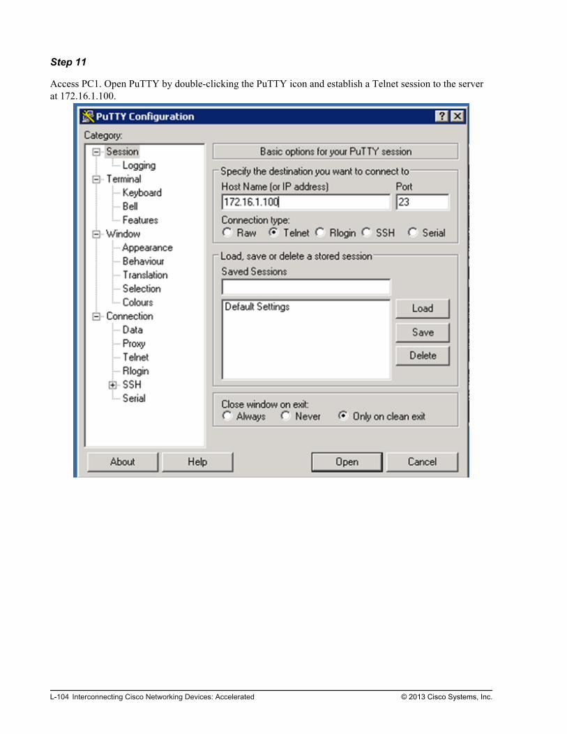
Step 11
Access PC1. Open PuTTY by double-clicking the PuTTY icon and establish a Telnet session to the serverat 172.16.1.100.
L-104 Interconnecting Cisco Networking Devices: Accelerated © 2013 Cisco Systems, Inc.

You should be successful.
© 2013 Cisco Systems, Inc. Lab Guide L-105

Step 12
Access PC2. Open PuTTY by double-clicking the PuTTY icon and establish a Telnet session to the serverat 172.16.1.100.
L-106 Interconnecting Cisco Networking Devices: Accelerated © 2013 Cisco Systems, Inc.

You should not be successful because the configured ACL blocks Telnet traffic from PC2 to the server.
© 2013 Cisco Systems, Inc. Lab Guide L-107

Step 13
Access PC1. Open Internet Explorer and try to reach the HTTP server at IP address 172.16.1.100. Use thecredentials that are provided in the Job Aids section of the document in order to log in.
You should be successful.
L-108 Interconnecting Cisco Networking Devices: Accelerated © 2013 Cisco Systems, Inc.

Step 14
Access PC2. Open Internet Explorer and try to reach the HTTP server at IP address 172.16.1.100. Use thecredentials that are provided in the Job Aids section of the document in order to log in.
You should be successful.
Activity VerificationNo additional verification is needed in this task.
© 2013 Cisco Systems, Inc. Lab Guide L-109

L-110 Interconnecting Cisco Networking Devices: Accelerated © 2013 Cisco Systems, Inc.

Lab 4-1: Configure and VerifyBasic IPv6
Activity OverviewObjectivesIn this activity, you will enable IPv6 globally and manually configure an IPv6 address on the interface.After completing this lab activity, you will be able to meet this objective:
Enable IPv6 support on a router and perform basic configuration

Visual ObjectiveThe figure illustrates what you will accomplish in this activity.
Visual Objective for Lab 4-1: Configure andVerify Basic IPv6
Server
PC1
PC2
SW1
SW2
Branch
HQ
© 2013 Cisco Systems, Inc.
Detailed Visual Objective
Branch HQ
Configure and verify
basic IPv6
© 2013 Cisco Systems, Inc.
Required ResourcesNo additional resources are required for this lab.
L-112 Interconnecting Cisco Networking Devices: Accelerated © 2013 Cisco Systems, Inc.

Command ListThe table describes the commands that are used in this activity. The commands are listed in alphabeticalorder so that you can easily locate the information that you need. Refer to this list if you need configurationor verification Cisco IOS command assistance during the lab activity.
CommandsCommand Description
configure terminal Enters configuration mode
exit Exits from the Telnet session
interface interface Enters interface configuration mode
ipv6 address ipv6_address/ipv6_mask Configures IPv6 address to the interface
ipv6 unicast-routing Enables IPv6 forwarding support on the router
ping destination_address Pings the specified IP address
show ipv6 interface interface Displays IPv6 status on the interface
telnet ip_address Uses Telnet to connect to the specified IP address
traceroute ip_address Traces to the specified IP address
Job AidsThese job aids are available to help you complete the lab activity.
The table shows the hardware that is used in the lab and the operating system that is running on the devices.
Device Hardware Operating System
Branch Cisco 2901 Integrated Services Router c2900-universalk9-mz.SPA.152-4.M1
HQ Cisco 2901 Integrated Services Router c2900-universalk9-mz.SPA.152-4.M1
The table shows the usernames and passwords that are used to access the lab equipment.
Device Username Password
Branch (console access) ccna cisco
Branch (enable password) / cisco
Topology and IP Addressing
Devices are connected with an Ethernet connection. The figure illustrates IP addresses that are used in thislab setup.
© 2013 Cisco Systems, Inc. Lab Guide L-113

Topology and IP Addressing
Internet
Server
Branch HQ
2001:DB8:D1A5:C900::1 2001:DB8:D1A5:C900::2
2001:DB8:AC10:100::64
© 2013 Cisco Systems, Inc.
The table shows the interface identification and IP addresses that are used in this lab setup.
Device Interface IP Address/Subnet Mask
Branch Gi0/1 2001:DB8:D1A5:C900::1/64
HQ Gi0/1 2001:DB8:D1A5:C900::2/64
HQ Loopback0 2001:DB8:AC10:100::64/64
Task 1: Enable IPv6 on the RouterIn this task, you will enable IPv6 globally and manually configure an IPv6 address on the interface.
The HQ router is already configured with an IPv6 address on the Gigabit Ethernet interface.
Activity ProcedureComplete the following steps:
Step 1
On the Branch router, enable IPv6 unicast routing.
Step 2
On the Branch router, configure an IPv6 address on the GigabitEthernet0/1 interface.
Step 3
Save the running configuration to the startup configuration.
L-114 Interconnecting Cisco Networking Devices: Accelerated © 2013 Cisco Systems, Inc.

Activity VerificationYou have completed this task when you attain this result:
Step 1
On the Branch router, verify IPv6 setup on the GigabitEthernet 0/1 interface.
Branch# show ipv6 interface GigabitEthernet 0/1GigabitEthernet0/1 is up, line protocol is up IPv6 is enabled, link-local address is FE80::FE99:47FF:FEE5:2599 No Virtual link-local address(es): Description: Link to HQ Global unicast address(es): 2001:DB8:D1A5:C900::1, subnet is 2001:DB8:D1A5:C900::/64 Joined group address(es): FF02::1 FF02::2 FF02::1:FF00:1 FF02::1:FFE5:2599 MTU is 1500 bytes ICMP error messages limited to one every 100 milliseconds ICMP redirects are enabled ICMP unreachables are sent ND DAD is enabled, number of DAD attempts: 1 ND reachable time is 30000 milliseconds (using 30000) ND advertised reachable time is 0 (unspecified) ND advertised retransmit interval is 0 (unspecified) ND router advertisements are sent every 200 seconds ND router advertisements live for 1800 seconds ND advertised default router preference is Medium Hosts use stateless autoconfig for addresses.
The GigabitEthernet0/1 interface is up and running. An IPv6 address is successfully enabled on theinterface.
Step 2
On the Branch router, ping the HQ router GigabitEthernet0/1 interface (2001:DB8:D1A5:C900::2). Theping should be successful.
Branch# ping 2001:db8:D1A5:C900::2Type escape sequence to abort.Sending 5, 100-byte ICMP Echos to 2001:DB8:D1A5:C900::2, timeout is 2 seconds:!!!!!Success rate is 100 percent (5/5), round-trip min/avg/max = 0/1/4 ms
© 2013 Cisco Systems, Inc. Lab Guide L-115

Step 3
On the Branch router, trace route to the IPv6 address 2001:DB8:D1A5:C900::2. You should see a responsefrom the HQ router.
Branch# traceroute 2001:db8:D1A5:C900::2Type escape sequence to abort.Tracing the route to 2001:DB8:D1A5:C900::2 1 2001:DB8:D1A5:C900::2 0 msec 4 msec 0 msec
Step 4
From the Branch router, use Telnet to connect to IPv6 address 2001:DB8:D1A5:C900::2. You should see asuccessful Telnet to the HQ router.
Branch# telnet 2001:db8:D1A5:C900::2Trying 2001:DB8:D1A5:C900::2 ... OpenHQ#
Disconnect from the HQ router by performing the exit command.
HQ# exit[Connection to 2001:db8:D1A5:C900::2 closed by foreign host]Branch#
L-116 Interconnecting Cisco Networking Devices: Accelerated © 2013 Cisco Systems, Inc.

Lab 4-2: Configure and VerifyStateless Autoconfiguration
Activity OverviewObjectivesIn this lab, you will enable and verify stateless autoconfiguration. When you have completed the activity,you will be able to meet this objective:
Configure and verify stateless autoconfiguration
Visual ObjectiveThe figure illustrates what you will accomplish in this activity.

Visual Objective for Lab 4-2: Configure andVerify Stateless Autoconfiguration
Server
PC1
PC2
SW1
SW2
Branch
HQ
© 2013 Cisco Systems, Inc.
Detailed Visual Objective
Branch HQ
Enable and verify IPv6
stateless autoconfiguration
© 2013 Cisco Systems, Inc.
Required ResourcesNo additional resources are required for this lab.
Command ListThe table describes the commands that are used in this activity. The commands are listed in alphabeticalorder so that you can easily locate the information that you need. Refer to this list if you need configurationor verification Cisco IOS command assistance during the lab activity.
L-118 Interconnecting Cisco Networking Devices: Accelerated © 2013 Cisco Systems, Inc.

CommandsCommand Description
configure terminal Enters configuration mode
exit Exits from the Telnet session
interface interface Enters interface configuration mode
ipv6 address autoconfig Enables IPv6 autoconfiguration on the interface
ping destination_address Pings the specified IP address
show ipv6 interface interface Displays IPv6 status on the interface
telnet ip_address Uses Telnet to connect to the specified IP address
traceroute ip_address Traces to the specified IP address
Job AidsThese job aids are available to help you complete the lab activity.
The table shows the hardware that is used in the lab and the operating system that is running on the devices.
Device Hardware Operating System
Branch Cisco 2901 Integrated Services Router c2900-universalk9-mz.SPA.152-4.M1
HQ Cisco 2901 Integrated Services Router c2900-universalk9-mz.SPA.152-4.M1
The table shows the usernames and passwords that are used to access the lab equipment.
Device Username Password
Branch (console access) ccna cisco
Branch (enable password) / cisco
Topology and IP Addressing
Devices are connected with an Ethernet connection. The figure illustrates IP addresses that are used in thislab setup.
© 2013 Cisco Systems, Inc. Lab Guide L-119

Topology and IP Addressing
Internet
Server
Branch HQ
2001:DB8:D1A5:C900::1 2001:DB8:D1A5:C900::2
2001:DB8:AC10:100::64
© 2013 Cisco Systems, Inc.
The table shows the interface identification and IP addresses that are used in this lab setup.
Device Interface IP Address/Subnet Mask
Branch Gi0/1 2001:DB8:D1A5:C900::1/64
HQ Gi0/1 2001:DB8:D1A5:C900::2/64
HQ Loopback0 2001:DB8:AC10:100::64/64
Task 1: Enable Stateless Autoconfiguration onthe RouterIn this task, you will first remove the configured IPv6 address from the interface and then configurestateless autoconfiguration on the interface.
The HQ router is already configured with an IPv6 address on the GigabitEthernet interface.
Activity ProcedureComplete the following steps:
L-120 Interconnecting Cisco Networking Devices: Accelerated © 2013 Cisco Systems, Inc.

Step 1
On the Branch router, verify the current GigabitEthernet 0/1 configuration.
Branch#show running-config interface GigabitEthernet 0/1Building configuration...Current configuration : 159 bytes!interface GigabitEthernet0/1 ip address dhcp ip nat outside ip virtual-reassembly in duplex auto speed auto ipv6 address 2001:DB8:D1A5:C900::1/64end
There is an IPv6 address configured on the interface.
Step 2
On the Branch router, remove the IPv6 address from the GigabitEthernet 0/1 interface.
Step 3
On the Branch router, configure stateless autoconfiguration on the GigabitEthernet 0/1 interface.
Activity VerificationYou have completed this task when you attain this result:
© 2013 Cisco Systems, Inc. Lab Guide L-121

Step 1
On the Branch router, verify the IPv6 setup on the GigabitEthernet 0/1 interface.
Branch#show ipv6 interface GigabitEthernet 0/1GigabitEthernet0/1 is up, line protocol is up IPv6 is enabled, link-local address is FE80::FE99:47FF:FEE5:2599 No Virtual link-local address(es): Description: Link to HQ Stateless address autoconfig enabled Global unicast address(es): 2001:DB8:D1A5:C900:FE99:47FF:FEE5:2599, subnet is 2001:DB8:D1A5:C900::/64 [EUI/CAL/PRE] valid lifetime 2591996 preferred lifetime 604796 Joined group address(es): FF02::1 FF02::2 FF02::1:FFE5:2599 MTU is 1500 bytes ICMP error messages limited to one every 100 milliseconds ICMP redirects are enabled ICMP unreachables are sent ND DAD is enabled, number of DAD attempts: 1 ND reachable time is 30000 milliseconds (using 30000) ND advertised reachable time is 0 (unspecified) ND advertised retransmit interval is 0 (unspecified) ND router advertisements are sent every 200 seconds ND router advertisements live for 1800 seconds ND advertised default router preference is Medium Hosts use stateless autoconfig for addresses.
The GigabitEthernet 0/1 interface is up and running. The IPv6 address is successfully set on the interface.The IPv6 prefix is the same as the one configured on the HQ router and the host portion of the IPv6 addressis calculated from the GigabitEthernet 0/1 interface MAC address.
Step 2
On the Branch router, ping the HQ router GigabitEthernet0/1 interface (2001:DB8:D1A5:C900::2). Theping should be successful.
Branch#ping 2001:db8:D1A5:C900::2Type escape sequence to abort.Sending 5, 100-byte ICMP Echos to 2001:DB8:D1A5:C900::2, timeout is 2 seconds:!!!!!Success rate is 100 percent (5/5), round-trip min/avg/max = 0/1/4 ms
L-122 Interconnecting Cisco Networking Devices: Accelerated © 2013 Cisco Systems, Inc.

Step 3
On the Branch router, trace route to the IPv6 address 2001:DB8:D1A5:C900::2. You should see a responsefrom the HQ router.
Branch#traceroute 2001:db8:D1A5:C900::2Type escape sequence to abort.Tracing the route to 2001:DB8:D1A5:C900::2 1 2001:DB8:D1A5:C900::2 0 msec 4 msec 0 msec
© 2013 Cisco Systems, Inc. Lab Guide L-123

L-124 Interconnecting Cisco Networking Devices: Accelerated © 2013 Cisco Systems, Inc.

Lab 4-3: Configure and VerifyIPv6 RoutingComplete this lab activity to practice what you learned in the related module.
ObjectivesIn this lab, you will configure and verify IPv6 routing by enabling static routing. When you have completedthe activity, you will be able to meet this objective:
Enable and verify static routing
Visual ObjectiveThe figure illustrates what you will accomplish in this activity.

Visual Objective for Lab 4-3: Configure andVerify IPv6 Routing
Server
PC1
PC2
SW1
SW2
Branch
HQ
© 2013 Cisco Systems, Inc.
Visual Objective
IPv6
QHhcnarB
Gi0/1
Configure IPv6
default route
2001:DB8:AC10:100::/642001:DB8:D1A5:C900::2/64
© 2013 Cisco Systems, Inc.
Command ListThe table describes the commands that are used in this activity. The commands are listed in alphabeticalorder so that you can easily locate the information that you need. Refer to this list if you need configurationor verification Cisco IOS command assistance during the lab activity.
L-126 Interconnecting Cisco Networking Devices: Accelerated © 2013 Cisco Systems, Inc.

CommandsCommand Description
[no] ipv6 route ::/0 interface next_hop Enables or disables the IPv6 default route.
configure terminal Enters configuration mode.
interface interface Enters interface configuration mode.
ping destination_address Pings the specified IP address.
show ipv6 route Displays the IPv6 routing table.
Job AidsThese Job Aids are available to help you complete the lab activity.
Pod Information
Each pod has two routers. The server is simulated on the HQ router by the IP address that is assigned to theloopback interface. One or two students will work in one pod.
The table shows the hardware that is used in the lab and the operating system that is running on the devices.
Device Hardware Operating System
Branch Cisco 2901 Integrated Services Router c2900-universalk9-mz.SPA.151-4.M4
HQ Cisco 2901 Integrated Services Router c2900-universalk9-mz.SPA.151-4.M4
There are no console or enable passwords that are set for the routers in the initial lab setup.
Topology and IP Addressing
Devices are connected with an Ethernet connection. The figure illustrates the IP addresses that are used inthis lab setup.
© 2013 Cisco Systems, Inc. Lab Guide L-127

Topology and IP Addressing
© 2013 Cisco Systems, Inc.
The table shows the interface identification and IP addresses that are used in this lab setup.
Device Interface IP Address/Subnet Mask
Branch Gi0/1 2001:DB8:D1A5:C900::1/64
HQ Gi0/1 2001:DB8:D1A5:C900::2/64
HQ Loopback0 2001:DB8:AC10:100::64/64
Task 1: Task: Enable IPv6 Static RoutingIn this task, you will configure an IPv6 default route on the Branch router.
Activity ProcedureComplete the following steps:
Step 1
On the Branch router, verify IPv6 connectivity to the IPv6 address 2001:DB8:AC10:100::64.
Branch#ping 2001:DB8:AC10:100::64Type escape sequence to abort.Sending 5, 100-byte ICMP Echos to 2001:DB8:AC10:100::64, timeout is 2 seconds:% No valid source address for destinationSuccess rate is 0 percent (0/1)
The ping is not successful because there is no valid route for network 2001:DB8:AC10:100::/64 in therouting table.
L-128 Interconnecting Cisco Networking Devices: Accelerated © 2013 Cisco Systems, Inc.
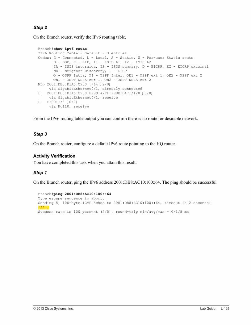
Step 2
On the Branch router, verify the IPv6 routing table.
Branch#show ipv6 routeIPv6 Routing Table - default - 3 entriesCodes: C - Connected, L - Local, S - Static, U - Per-user Static route B - BGP, R - RIP, I1 - ISIS L1, I2 - ISIS L2 IA - ISIS interarea, IS - ISIS summary, D - EIGRP, EX - EIGRP external ND - Neighbor Discovery, l - LISP O - OSPF Intra, OI - OSPF Inter, OE1 - OSPF ext 1, OE2 - OSPF ext 2 ON1 - OSPF NSSA ext 1, ON2 - OSPF NSSA ext 2NDp 2001:DB8:D1A5:C900::/64 [2/0] via GigabitEthernet0/1, directly connectedL 2001:DB8:D1A5:C900:FE99:47FF:FEDE:B471/128 [0/0] via GigabitEthernet0/1, receiveL FF00::/8 [0/0] via Null0, receive
From the IPv6 routing table output you can confirm there is no route for desirable network.
Step 3
On the Branch router, configure a default IPv6 route pointing to the HQ router.
Activity VerificationYou have completed this task when you attain this result:
Step 1
On the Branch router, ping the IPv6 address 2001:DB8:AC10:100::64. The ping should be successful.
Branch#ping 2001:DB8:AC10:100::64Type escape sequence to abort.Sending 5, 100-byte ICMP Echos to 2001:DB8:AC10:100::64, timeout is 2 seconds:!!!!!Success rate is 100 percent (5/5), round-trip min/avg/max = 0/1/8 ms
© 2013 Cisco Systems, Inc. Lab Guide L-129

Step 2
On the Branch router, verify the IPv6 routing table.
Branch#show ipv6 route IPv6 Routing Table - default - 4 entriesCodes: C - Connected, L - Local, S - Static, U - Per-user Static route B - BGP, R - RIP, I1 - ISIS L1, I2 - ISIS L2 IA - ISIS interarea, IS - ISIS summary, D - EIGRP, EX - EIGRP external ND - Neighbor Discovery, l - LISP O - OSPF Intra, OI - OSPF Inter, OE1 - OSPF ext 1, OE2 - OSPF ext 2 ON1 - OSPF NSSA ext 1, ON2 - OSPF NSSA ext 2S ::/0 [1/0] via 2001:DB8:D1A5:C900::2, GigabitEthernet0/1NDp 2001:DB8:D1A5:C900::/64 [2/0] via GigabitEthernet0/1, directly connectedL 2001:DB8:D1A5:C900:FE99:47FF:FEDE:B471/128 [0/0] via GigabitEthernet0/1, receiveL FF00::/8 [0/0] via Null0, receive
There is still no route for network 2001:DB8:AC10:100::/64, but you can see the static default route. TheBranch router uses the default route to reach IPv6 networks that are not present in the routing table.
L-130 Interconnecting Cisco Networking Devices: Accelerated © 2013 Cisco Systems, Inc.

Lab 5-1: ConfiguringExpanded SwitchedNetworks
Activity OverviewObjectivesIn this lab, you will configure two switches to meet specified VLAN requirements. After completing thisactivity, you will be able to meet these objectives:
Configure VLANs
Configure trunking
Configure router with a trunk link

Visual ObjectiveThe figure illustrates what you will accomplish in this activity.
Visual Objective for Lab 5-1: ConfiguringExpanded Switched Networks
Server
PC1
PC2
SW1
SW2
Branch
HQ
© 2013 Cisco Systems, Inc.
Detailed Visual Objective
Branch
PC1
VLAN 10
Configure VLANs and
assign user ports to the
proper VLAN
SW1
SW2
Configure trunking
Configure a router
with a trunk link
Fa0/1
Fa0/1
Fa0/3
Fa0/3PC2
VLAN 20
Gi0/1
Fa0/13
© 2013 Cisco Systems, Inc.
Required ResourcesThere are no additional resources required for this lab.
L-132 Interconnecting Cisco Networking Devices: Accelerated © 2013 Cisco Systems, Inc.

Command ListThe table describes the commands that are used in this activity. The commands are listed in alphabeticalorder so that you can easily locate the information that you need. Refer to this list if you need configurationcommand assistance during the lab activity.
Cisco IOS CommandsCommand Description
encapsulation dot1q vlan Enables IEEE 802.1Q encapsulation of traffic on a specifiedsubinterface in VLANs. This command can be entered when you arein interface configuration mode.
interface interface_nameinterface_number
Enters interface configuration mode for the specified interface.
ip address ip_address network_mask Sets an IP address, along with the subnet mask, on an interface. Enterinterface configuration mode to issue this command.
show interfaces trunk Displays trunking information.
show vlan Displays VLAN information.
show vlans When you configure a router on a stick, use this command to verifytrunking and VLANs.
[no] shutdown Disables or enables an interface. Issue this command from interfaceconfiguration mode.
switchport access vlan vlan Assigns a port to a VLAN. Issue this command from interfaceconfiguration mode.
switchport mode mode Interface configuration mode command. There are four options. Thetwo non-negotiating modes are trunk and switch, and the two DTPnegotiation modes are dynamic auto and dynamic desirable.
switchport trunk allowed vlan vlan_list Specifies VLANs from which traffic is allowed over the trunk link.
vlan vlan_number Creates the VLAN that is specified. Issue this command from globalconfiguration mode.
Microsoft Windows CommandsCommand Description
ping ip_address Issues a ping to the specified IP address
tracert ip_address Issues a traceroute to the specified IP address
Job AidsThese job aids are available to help you complete the lab activity.
The table shows the hardware that is used in the lab and the operating system that is running on the devices.
© 2013 Cisco Systems, Inc. Lab Guide L-133

Device Hardware Operating System
Branch Cisco 2901 Integrated Services Router c2900-universalk9-mz.SPA.152-4.M1
Headquarters
Cisco 2901 Integrated Services Router c2900-universalk9-mz.SPA.152-4.M1
SW1 Catalyst 2960 Series Switch c2960-lanbasek9-mz.150-1.SE3
SW2 Catalyst 2960 Series Switch c2960-lanlitek9-mz.150-1.SE3
PC1 Any PC Microsoft Windows 7
PC2 Any PC Microsoft Windows 7
The table shows usernames and passwords that are used to access the lab devices.
Device Username Password
PC1 Administrator admin
PC2 Administrator admin
Branch (console access) ccna cisco
Branch (enable password) / cisco
SW1 (console access) ccna cisco
SW1 (enable password) / cisco
Server (HTTP) ccna cisco
Topology and IP Addressing
Devices are connected with Ethernet links. The figure illustrates the interface identification and IPaddresses that will be used in this lab.
Topology and IP Addressing
InternetServer
PC1
PC2
SW1
Branch
HQ
Fa0/1
Gi0/0
Fa0/13
Fa0/3
Gi0/1
209.165.201.1
Gi0/1
209.165.201.2
10.1.1.100
10.1.1.11
VLAN1:10.1.1.1 172.16.1.100
a0/3
Fa0/3
SW2
Fa0/1
10.1.1.101 10.1.1.12
© 2013 Cisco Systems, Inc.
L-134 Interconnecting Cisco Networking Devices: Accelerated © 2013 Cisco Systems, Inc.

The table shows the interface identification and IP addresses that are used in this lab setup.
Device Interface IP Address/Subnet Mask
Branch Gi0/1 209.165.201.1/27
Branch Gi0/0 10.1.1.1/24
Headquarters Gi0/1 209.165.201.2/27
Headquarters Loopback0 172.16.1.100/24
SW1 VLAN1 10.1.1.11/24
SW2 VLAN1 10.1.1.12/24
PC1 Ethernet adapter local area connection 10.1.1.100/24
PC2 Ethernet adapter local area connection 10.1.1.101/24
Task 1: Configure a VLANIn this task, you will create VLANs and assign the ports that are specified to them.
Activity ProcedureComplete the following steps:
Step 1
Access switch SW2.
For the purpose of management, configure the VLAN 1 interface with the IP address 10.1.1.12/24.
© 2013 Cisco Systems, Inc. Lab Guide L-135

Step 2
Access PC2.
Assign the IP address 10.1.1.101/24 to it. The default gateway should be set to the IP address of a Branchrouter.
Step 3
Access PC1 and ping PC2 (10.1.1.101).
The ping should be successful because ports on both PCs are access ports belonging to VLAN 1.
C:\Users\Administrator> ping 10.1.1.101Pinging 10.1.1.101 with 32 bytes of data:Reply from 10.1.1.101: bytes=32 time<3ms TTL=128Reply from 10.1.1.101: bytes=32 time<3ms TTL=128Reply from 10.1.1.101: bytes=32 time<2ms TTL=128Reply from 10.1.1.101: bytes=32 time<2ms TTL=128Ping statistics for 10.1.1.101: Packets: Sent = 4, Received = 4, Lost = 0 (0% loss), Approximate round trip times in milli-seconds: Minimum = 2ms, Maximum = 3ms, Average = 3ms
L-136 Interconnecting Cisco Networking Devices: Accelerated © 2013 Cisco Systems, Inc.

Step 4
On both switches, SW1 and SW2, create VLANs 10 and 20.
Step 5
On SW1, assign the port to which PC1 connects (FastEthernet0/1) to VLAN 10.
On SW2, assign the port to which PC2 connects (FastEthernet0/1) to VLAN 20.
Step 6
Save the running configuration to the startup configuration on both switches.
Step 7
Change the IP address of PC1 to 10.1.10.100/24. Set the default gateway to 10.1.10.1, which you will laterconfigure on the Branch router.
This step provides PC1 addressing in accordance with its VLAN assignment.
© 2013 Cisco Systems, Inc. Lab Guide L-137

Step 8
Change the IP address of PC2 to 10.1.20.100/24. Set the default gateway to 10.1.20.1, which you will laterconfigure on the Branch router.
This step provides PC2 addressing in accordance with its VLAN assignment.
Activity VerificationYou have completed this task when you attain these results:
L-138 Interconnecting Cisco Networking Devices: Accelerated © 2013 Cisco Systems, Inc.

Step 1
On SW1 and SW2, verify that VLANs 10 and 20 are present.
SW1 should have FastEthernet0/1 belonging to VLAN 10, and SW2 should have FastEthernet0/1 belongingto VLAN 20.
SW1# show vlanVLAN Name Status Ports---- -------------------------------- --------- -------------------------------1 default active Fa0/2, Fa0/3, Fa0/4, Fa0/5 Fa0/6, Fa0/7, Fa0/8, Fa0/9 Fa0/10, Fa0/11, Fa0/12, Fa0/13 Fa0/14, Fa0/15, Fa0/16, Fa0/17 Fa0/18, Fa0/19, Fa0/20, Fa0/21 Fa0/22, Fa0/23, Fa0/24, Gi0/1 Gi0/210 VLAN0010 active Fa0/120 VLAN0020 active1002 fddi-default act/unsup1003 token-ring-default act/unsup1004 fddinet-default act/unsup1005 trnet-default act/unsup
SW2# show vlanVLAN Name Status Ports---- -------------------------------- --------- -------------------------------1 default active Fa0/2, Fa0/3, Fa0/4, Fa0/5 Fa0/6, Fa0/7, Fa0/8, Fa0/9 Fa0/10, Fa0/11, Fa0/12, Fa0/13 Fa0/14, Fa0/15, Fa0/16, Fa0/17 Fa0/18, Fa0/19, Fa0/20, Fa0/21 Fa0/22, Fa0/23, Fa0/24, Gi0/1 Gi0/210 VLAN0010 active20 VLAN0020 active Fa0/11002 fddi-default act/unsup1003 token-ring-default act/unsup1004 fddinet-default act/unsup1005 trnet-default act/unsup<output omitted>
© 2013 Cisco Systems, Inc. Lab Guide L-139

Step 2
At this point, PC1 belongs to VLAN 10, and PC2 belongs to VLAN 20.
From PC1, ping PC2 (10.1.20.100).
The connectivity test should not be successful. You first need to configure a trunk between switches thatwill carry traffic from both VLANs and then configure a Layer 3 device that will route between those twoVLANs.
C:\Users\Administrator> ping 10.1.20.100Pinging 10.1.20.100 with 32 bytes of data:Reply from 10.1.10.100: Destination host unreachable.Reply from 10.1.10.100: Destination host unreachable.Reply from 10.1.10.100: Destination host unreachable.Reply from 10.1.10.100: Destination host unreachable.Ping statistics for 10.1.20.100: Packets: Sent = 4, Received = 4, Lost = 0 (0% loss),
Task 2: Configure the Link Between Switches as aTrunkIn this task, you will configure the link between two switches as a trunk. This configuration will enable thelink to carry traffic from multiple VLANs.
Activity ProcedureComplete the following steps:
Step 1
On switch SW1, configure the link toward switch SW2 (FastEthernet0/3) as a trunk. To follow the bestpractice, allow only VLANs 1, 10, and 20 to cross the trunk. You can limit which VLANs are allowed totraverse the trunk link with the switchport trunk allowed vlan command.
By default, ports are in DTP negotiation mode (dynamic auto). This mode presents a security risk, so thebest practice is to configure the ports manually to non-negotiation modes (access or trunk).
Repeat the same procedure on SW2.
Step 2
Save the running configuration to the startup configuration on both switches.
L-140 Interconnecting Cisco Networking Devices: Accelerated © 2013 Cisco Systems, Inc.

Step 3
On switch SW1, verify that the link toward SW2 is trunking and that VLANs 1, 10, and 20 are the onlyVLANs that are allowed.
SW1# show interfaces trunkPort Mode Encapsulation Status Native vlanFa0/3 on 802.1q trunking 1Port Vlans allowed on trunkFa0/3 1,10,20<output omitted>
On switch SW2, verify that the link toward SW1 is trunking and that VLANs 1, 10, and 20 are the onlyVLANs that are allowed.
SW2# show interfaces trunkPort Mode Encapsulation Status Native vlanFa0/3 on 802.1q trunking 1Port Vlans allowed on trunkFa0/3 1,10,20<output omitted>
Step 4
At this point, PC1 belongs to VLAN 10, and PC2 belongs to VLAN 20. The link between the two switchesis configured to carry more than one VLAN. It is a trunk.
From PC1, ping PC2 (10.1.20.100).
The connectivity test will not be successful. You first need to configure a trunk between switches that willcarry traffic from both VLANs and then configure a Layer 3 device that will route between those twoVLANs.
C:\Users\Administrator> ping 10.1.20.100Pinging 10.1.20.100 with 32 bytes of data:Reply from 10.1.20.100: Destination host unreachable.Reply from 10.1.20.100: Destination host unreachable.Reply from 10.1.20.100: Destination host unreachable.Reply from 10.1.20.100: Destination host unreachable.Ping statistics for 10.1.20.100: Packets: Sent = 4, Received = 4, Lost = 0 (0% loss),
Activity VerificationNo additional verification is needed in this task.
Task 3: Configure a Trunk Link on the RouterIn this task, you will configure a trunk link on the Branch router. It will serve as a Layer 3 device that willroute between the two VLANs.
© 2013 Cisco Systems, Inc. Lab Guide L-141

Activity ProcedureComplete the following steps:
Step 1
On switch SW1, configure the link toward the Branch router (FastEthernet0/13) as a trunk.
Step 2
Save the running configuration to the startup configuration on the SW1 switch.
Step 3
On the Branch router, remove the IP address from the GigabitEthernet0/0 interface.
Step 4
On the Branch router, configure three subinterfaces. Subinterface GigabitEthernet0/0.1 should have an IPaddress of 10.1.1.1/24 and belong to VLAN 1. Subinterface GigabitEthernet0/0.10 should have an IPaddress of 10.1.10.1/24 and belong to VLAN 10. Subinterface GigabitEthernet0/0.20 should have an IPaddress of 10.1.20.1/24 and belong to VLAN 20.
Step 5
Save the running configuration to the startup configuration on the Branch router.
L-142 Interconnecting Cisco Networking Devices: Accelerated © 2013 Cisco Systems, Inc.

Step 6
On the Branch router, verify that you have interface IP addresses that are configured in VLANs 1, 10, and20.
Branch# show vlans Virtual LAN ID: 1 (IEEE 802.1Q Encapsulation) vLAN Trunk Interface: GigabitEthernet0/0.1 This is configured as native Vlan for the following interface(s) :GigabitEthernet0/0 Native-vlan Tx-type: Untagged Protocols Configured: Address: Received: Transmitted: IP 10.1.1.1 0 0 Other 0 2 2 packets, 518 bytes input 2 packets, 435 bytes outputVirtual LAN ID: 10 (IEEE 802.1Q Encapsulation) vLAN Trunk Interface: GigabitEthernet0/0.10 Protocols Configured: Address: Received: Transmitted: IP 10.1.10.1 0 0 Other 0 1 0 packets, 0 bytes input 1 packets, 46 bytes outputVirtual LAN ID: 20 (IEEE 802.1Q Encapsulation) vLAN Trunk Interface: GigabitEthernet0/0.20 Protocols Configured: Address: Received: Transmitted: IP 10.1.20.1 0 0 Other 0 1 0 packets, 0 bytes input 1 packets, 46 bytes output
Activity VerificationYou have completed this task when you attain these results:
Step 1
Access PC1. Issue a ping command from PC1 to PC2 (10.1.20.100).
The attempt should be successful. The first ping or first few pings might fail due to the ARP process.
C:\Users\Administrator> ping 10.1.20.100Pinging 10.1.20.100 with 32 bytes of data:Reply from 10.1.20.100: bytes=32 time<3ms TTL=128Reply from 10.1.20.100: bytes=32 time<3ms TTL=128Reply from 10.1.20.100: bytes=32 time<2ms TTL=128Reply from 10.1.20.100: bytes=32 time<2ms TTL=128Ping statistics for 10.1.20.100: Packets: Sent = 4, Received = 4, Lost = 0 (0% loss), Approximate round trip times in milli-seconds: Minimum = 2ms, Maximum = 3ms, Average = 3ms
© 2013 Cisco Systems, Inc. Lab Guide L-143

Step 2
From PC1, use the traceroute (tracert command) utility to trace the path from PC1 to PC2.
Notice that the traffic goes through the Branch router.
C:\Users\Administrator> tracert 10.1.20.100Tracing route to 10.1.20.100 over a maximum of 30 hops 1 4 ms 1 ms 1 ms 10.1.10.1 2 2 ms 1 ms 1 ms 10.1.20.100Trace complete.
L-144 Interconnecting Cisco Networking Devices: Accelerated © 2013 Cisco Systems, Inc.

Lab 5-2: Configuring DHCPServer
Activity OverviewObjectivesIn this lab, you will assign IP addresses to network devices using DHCP. After completing this activity, youwill be able to meet these objectives:
Configure a DHCP server
Exclude specific IP addresses from DHCP pools
Configure a DHCP relay agent
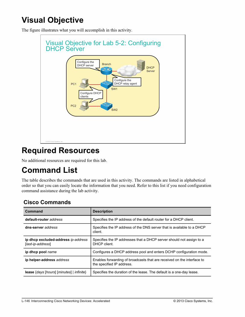
Visual ObjectiveThe figure illustrates what you will accomplish in this activity.
Visual Objective for Lab 5-2: ConfiguringDHCP Server
DHCP
Server
PC1
PC2
SW1
SW2
BranchConfigure the
DHCP server
Configure the
DHCP relay agent
Configure DHCP
clients
© 2013 Cisco Systems, Inc.
Required ResourcesNo additional resources are required for this lab.
Command ListThe table describes the commands that are used in this activity. The commands are listed in alphabeticalorder so that you can easily locate the information that you need. Refer to this list if you need configurationcommand assistance during the lab activity.
Cisco CommandsCommand Description
default-router address Specifies the IP address of the default router for a DHCP client.
dns-server address Specifies the IP address of the DNS server that is available to a DHCPclient.
ip dhcp excluded-address ip-address[last-ip-address]
Specifies the IP addresses that a DHCP server should not assign to aDHCP client.
ip dhcp pool name Configures a DHCP address pool and enters DCHP configuration mode.
ip helper-address address Enables forwarding of broadcasts that are received on the interface tothe specified IP address.
lease {days [hours] [minutes] | infinite} Specifies the duration of the lease. The default is a one-day lease.
L-146 Interconnecting Cisco Networking Devices: Accelerated © 2013 Cisco Systems, Inc.

Command Description
network network-number [mask |prefix-length]
Defines addresses in the DHCP pool. Optionally, defines the subnetmask or prefix length. Either of these parameters determines whichportion of the specified network number refers to the network part.
show ip dhcp binding Displays a list of all DHCP address bindings.
show ip interface brief Displays a brief summary of the IP information and status of an interface.
show running-config Displays the running configuration.
Microsoft Windows CommandsCommand Description
ping ip_address Issues a ping to the specified IP address.
ipconfig {/all} Displays IP address information. Uses option /all to display all details.
ipconfig /release Releases the DHCP leases.
ipconfig /renew Renews all network adapters and initiates a DHCP discover messageif DHCP is enabled on the interface.
Job AidsThese job aids are available to help you complete the lab activity.
The table shows the hardware that is used in the lab and the operating system that is running on the devices.
Device Hardware Operating System
Branch Cisco 2901 Integrated Services Router c2900-universalk9-mz.SPA.152-4.M1
Headquarters
Cisco 2901 Integrated Services Router c2900-universalk9-mz.SPA.152-4.M1
SW1 Catalyst 2960 Series Switch c2960-lanbasek9-mz.150-1.SE3
SW2 Catalyst 2960 Series Switch c2960-lanlitek9-mz.150-1.SE3
PC1 Any PC Microsoft Windows 7
PC2 Any PC Microsoft Windows 7
The table shows the usernames and passwords that are used to access the lab equipment.
Device Username Password
PC1 Administrator admin
PC2 Administrator admin
Branch (console access) ccna cisco
Branch (enable password) / cisco
SW1 (console access) ccna cisco
SW1 (enable password) / cisco
© 2013 Cisco Systems, Inc. Lab Guide L-147

Topology and IP Addressing
Devices are connected with Ethernet links. The figure illustrates the interface identification and IPaddresses that are used in this lab setup.
Topology and IP Addressing
SW2
10.1.1.12
DHCP
Server
PC1
PC2
SW1
Branch
HQ
Fa0/1
Fa0/13
Fa0/3
Gi0/1
209.165.201.1
Gi0/1
209.165.201.2
10.1.10.100
10.1.20.100
10.1.1.11
Gi0/0—VLAN 1:10.1.1.1
Gi0/0.10—VLAN 10: 10.1.10.1
Gi0/0.20—VLAN 20: 10.1.20.1 172.16.1.100
Fa0/1
Fa0/3
© 2013 Cisco Systems, Inc.
The table shows the interface identification and IP addresses that are used in this lab setup.
Device Interface IP Address/Subnet Mask
Branch Gi0/1 209.165.201.1/27
Branch Gi0/0.1 10.1.1.1/24
Branch Gi0/0.10 10.1.10.1/24
Branch Gi0/0.20 10.1.20.1/24
HQ Gi0/1 209.165.201.2/27
HQ Loopback0 172.16.1.100/24
SW1 VLAN1 10.1.1.11/24
SW2 VLAN1 10.1.1.12/24
PC1 Ethernet adapter local area connection 10.1.10.100/24
PC2 Ethernet adapter local area connection 10.1.20.100/24
VLAN Setup
Three VLANs are configured on the switches. VLAN 1 is used for switch management, VLAN 10 is usedto connect PC1, and VLAN 20 is used to connect PC2. A trunk is enabled between the switches andbetween the SW1 switch and the Branch router. The figure illustrates the trunk and VLAN setup.
L-148 Interconnecting Cisco Networking Devices: Accelerated © 2013 Cisco Systems, Inc.
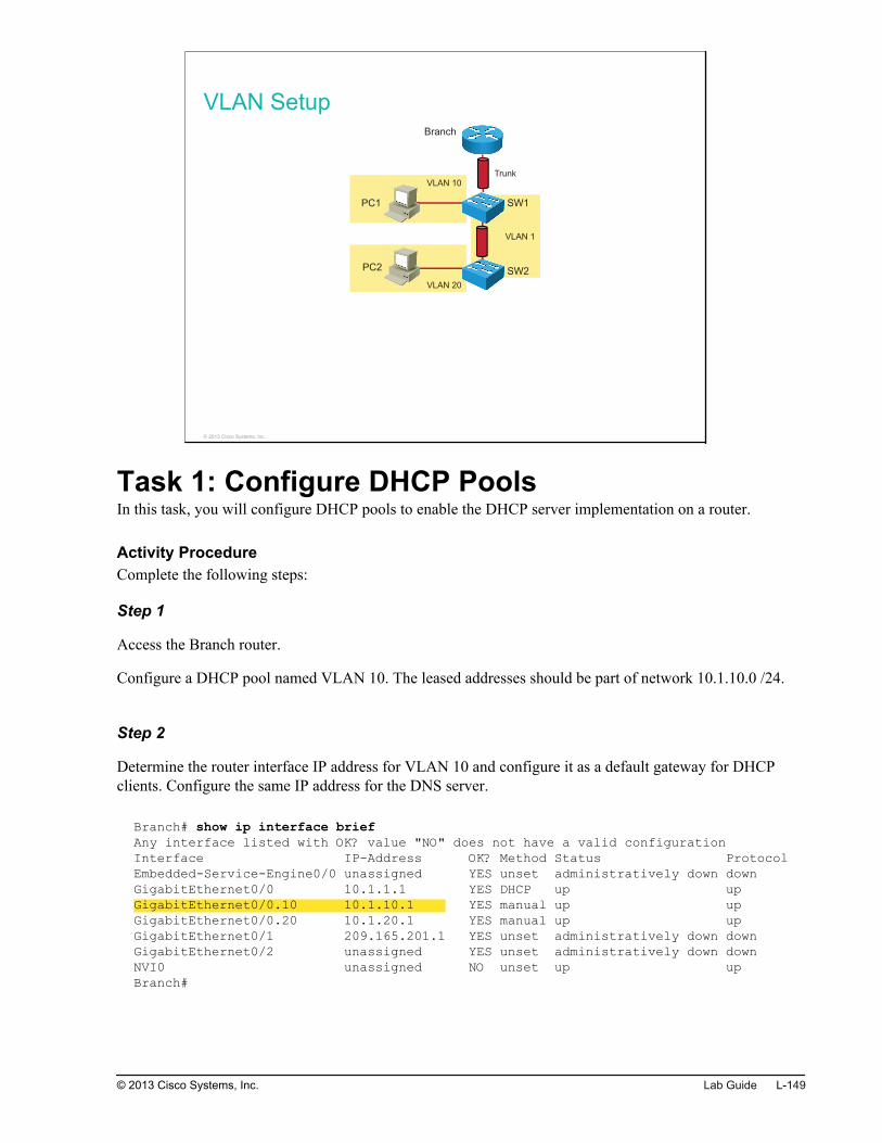
VLAN Setup
VLAN 1
VLAN 10
VLAN 20
PC1
PC2
SW1
SW2
Branch
Trunk
© 2013 Cisco Systems, Inc.
Task 1: Configure DHCP PoolsIn this task, you will configure DHCP pools to enable the DHCP server implementation on a router.
Activity ProcedureComplete the following steps:
Step 1
Access the Branch router.
Configure a DHCP pool named VLAN 10. The leased addresses should be part of network 10.1.10.0 /24.
Step 2
Determine the router interface IP address for VLAN 10 and configure it as a default gateway for DHCPclients. Configure the same IP address for the DNS server.
Branch# show ip interface briefAny interface listed with OK? value "NO" does not have a valid configurationInterface IP-Address OK? Method Status ProtocolEmbedded-Service-Engine0/0 unassigned YES unset administratively down downGigabitEthernet0/0 10.1.1.1 YES DHCP up upGigabitEthernet0/0.10 10.1.10.1 YES manual up upGigabitEthernet0/0.20 10.1.20.1 YES manual up upGigabitEthernet0/1 209.165.201.1 YES unset administratively down downGigabitEthernet0/2 unassigned YES unset administratively down downNVI0 unassigned NO unset up upBranch#
© 2013 Cisco Systems, Inc. Lab Guide L-149

Step 3
Change the default lease time to 2 hours.
Step 4
Save the running configuration to the startup configuration on the Branch router.
Step 5
Access PC1.
Open the network adapter settings and edit the IPv4 settings. Set them to obtain an IP address and DNSaddress automatically.
L-150 Interconnecting Cisco Networking Devices: Accelerated © 2013 Cisco Systems, Inc.

Step 6
Verify that PC1 has obtained an IP address dynamically by executing a DHCP verification command on theBranch router.
Branch# show ip dhcp bindingBindings from all pools not associated with VRF:IP address Client-ID/ Lease expiration Type Hardware address/ User name10.1.10.2 0100.0c29.8fa8.a6 Oct 25 2012 12:18 PM Automatic
In addition, verify the IP address settings using the command prompt on PC1.
C:\Windows\system32> ipconfig /all<output omitted>Ethernet adapter LAB: Connection-specific DNS Suffix . : Description . . . . . . . . . . . : VMware Accelerated AMD PCNet Adapter #2 Physical Address. . . . . . . . . : 00-0C-29-45-32-BE DHCP Enabled. . . . . . . . . . . : Yes Autoconfiguration Enabled . . . . : Yes Link-local IPv6 Address . . . . . : fe80::8c6e:3fe3:ca7e:c7c7%13(Preferred) IPv4 Address. . . . . . . . . . . : 10.1.10.2(Preferred) Subnet Mask . . . . . . . . . . . : 255.255.255.0 Lease Obtained. . . . . . . . . . : Friday, October 19, 2012 2:39:34 PM Lease Expires . . . . . . . . . . : Friday, October 19, 2012 4:39:34 PM Default Gateway . . . . . . . . . : 10.1.10.1 DHCP Server . . . . . . . . . . . : 10.1.10.1 DHCPv6 IAID . . . . . . . . . . . : 285215785 DHCPv6 Client DUID. . . . . . . . : 00-01-00-01-13-3B-A1-51-00-0C-29-87-5C-B5 DNS Servers . . . . . . . . . . . : 10.1.10.1 NetBIOS over Tcpip. . . . . . . . : Disabled
Step 7
Configure a DHCP pool for VLAN 20.
The leased addresses should be part of network 10.1.20.0 /24. For the DNS server and default gateway, usethe router VLAN 20 interface (10.1.20.1). Set the lease time to 12 hours.
© 2013 Cisco Systems, Inc. Lab Guide L-151

Step 8
On the Branch router, verify the configured pools by using the show ip dhcp pool verification command.
Branch# show ip dhcp poolPool VLAN10 : Utilization mark (high/low) : 100 / 0 Subnet size (first/next) : 0 / 0 Total addresses : 254 Leased addresses : 1 Pending event : none 1 subnet is currently in the pool : Current index IP address range Leased addresses 10.1.10.3 10.1.10.1 - 10.1.10.254 1Pool VLAN20 : Utilization mark (high/low) : 100 / 0 Subnet size (first/next) : 0 / 0 Total addresses : 254 Leased addresses : 0 Pending event : none 1 subnet is currently in the pool : Current index IP address range Leased addresses 10.1.20.1 10.1.20.1 - 10.1.20.254 0
Step 9
Access PC2.
Open the network adapter settings and edit the IPv4 settings. Set them to obtain an IP address and DNSaddress automatically.
Step 10
Check the DHCP address bindings on the router to verify that PC2 has obtained an IP address dynamically.
Activity VerificationYou have completed this task when you attain these results:
Step 1
You verified that both PC1 and PC2 have dynamically assigned IP addresses.
L-152 Interconnecting Cisco Networking Devices: Accelerated © 2013 Cisco Systems, Inc.

Step 2
You have successfully verified connectivity between the PCs using the ping command:
C:\Windows\system32> ping 10.1.20.2Pinging 10.1.20.2 with 32 bytes of data:Reply from 10.1.20.2: bytes=32 time=30ms TTL=127Reply from 10.1.20.2: bytes=32 time=1ms TTL=127Reply from 10.1.20.2: bytes=32 time=1ms TTL=127Reply from 10.1.20.2: bytes=32 time=1ms TTL=127Ping statistics for 10.1.20.2: Packets: Sent = 4, Received = 4, Lost = 0 (0% loss),Approximate round trip times in milli-seconds: Minimum = 1ms, Maximum = 30ms, Average = 8ms
Task 2: Exclude Specific IP Addresses fromDHCP PoolsThe configured DHCP server can assign any valid IP address from the pool to DHCP clients. Commonly,certain IP addresses within the subnet that are assigned to the DCHP pool are configured manually on someend hosts, such as servers or printers. In this task, you will configure DHCP to limit the valid IP addresseswithin the pool to the desired uses.
Activity ProcedureComplete the following steps:
Step 1
On the Branch router, change the configuration of the DHCP server to assign IP addresses to DHCP clientsonly from x.x.x.100 to x.x.x.150 within the configured pools.
Step 2
Save the running configuration to the startup configuration on the Branch router.
Step 3
To verify the DHCP configuration, connect to PC1, enter the command prompt, and release the existingDHCP lease with the ipconfig /release command.
Repeat this step on PC2.
Step 4
Instruct PC1 to request new a DCHP lease by issuing the ipconfig /renew command.
Repeat this step on PC2.
© 2013 Cisco Systems, Inc. Lab Guide L-153

Activity VerificationYou have completed this task when you have attained this result:
Step 1
On the Branch router, verify that PC1 and PC2 have been assigned new IP addresses:
Branch# show ip dhcp bindingBindings from all pools not associated with VRF:IP address Client-ID/ Lease expiration Type Hardware address/ User name10.1.10.100 0100.0c29.4532.be Oct 19 2012 03:39 PM Automatic10.1.20.100 0100.0c29.8807.34 Oct 20 2012 01:24 AM Automatic
Task 3: Configure DHCP Relay AgentIn this task, you will reconfigure the Branch router to support a centralized DHCP server.
Activity ProcedureComplete the following steps:
Step 1
Access the Branch router and remove the DHCP server configuration.
Step 2
Verify that no DHCP server configuration is present on the Branch router by using a DHCP pool showcommand.
Branch# show ip dhcp poolBranch#
Step 3
Configure a DHCP relay agent on the Branch router to forward DHCP messages to a centralized DHCPserver with IP address 172.16.1.100. Configure the relay agent on both logical subinterfaces, which are partof VLAN 10 and VLAN 20.
Step 4
Save the running configuration to the startup configuration on the Branch router.
Step 5
Access PC1 and release the current DHCP lease.
L-154 Interconnecting Cisco Networking Devices: Accelerated © 2013 Cisco Systems, Inc.

Step 6
Renew the DHCP lease using the ipconfig /renew command and verify that PC1 has dynamically obtainedan IP address from the 10.1.10.200–10.1.10.254 range.
C:\Windows\system32> ipconfigWindows IP ConfigurationEthernet adapter LAB: Connection-specific DNS Suffix . : Link-local IPv6 Address . . . . . : fe80::1844:cd29:1d13:1905%13 IPv4 Address. . . . . . . . . . . : 10.1.10.200 Subnet Mask . . . . . . . . . . . : 255.255.255.0 Default Gateway . . . . . . . . . : 10.1.10.1<output omitted>
Step 7
Renew the DHCP lease using the ipconfig /renew command and verify that PC2 has dynamically obtainedan IP address from the 10.1.20.200–10.1.20.254 range.
C:\Windows\system32> ipconfig /all<output omitted>Ethernet adapter LAB: Connection-specific DNS Suffix . : Description . . . . . . . . . . . : VMware Accelerated AMD PCNet Adapter #2 Physical Address. . . . . . . . . : 00-0C-29-50-EB-9D DHCP Enabled. . . . . . . . . . . : Yes Autoconfiguration Enabled . . . . : Yes Link-local IPv6 Address . . . . . : fe80::b423:4279:f330:b1f5%13(Preferred) IPv4 Address. . . . . . . . . . . : 10.1.20.200 Subnet Mask . . . . . . . . . . . : 255.255.255.0 Lease Obtained. . . . . . . . . . : Tuesday, October 23, 2012 11:04:21 AM Lease Expires . . . . . . . . . . : Tuesday, October 23, 2012 11:04:21 PM Default Gateway . . . . . . . . . : 10.1.20.1 DHCP Server . . . . . . . . . . . : 209.165.201.2<output omitted>
Activity VerificationNo additional verification is needed in this task.
Task 4: Manually Assign IP AddressesIn this task, you will manually assign IP addresses on both PCs.
Activity ProcedureComplete the following steps:
© 2013 Cisco Systems, Inc. Lab Guide L-155

Step 1
Access both PCs and edit the IPv4 network settings. Manually set the parameters according to the table.
IP AddressingDevice IP Address Subnet Mask Default Gateway
PC1 10.1.10.100 255.255.255.0 10.1.10.1
PC2 10.1.20.100 255.255.255.0 10.1.20.1
On PC1:
On PC2:
L-156 Interconnecting Cisco Networking Devices: Accelerated © 2013 Cisco Systems, Inc.

Step 2
To verify the manual settings, use the ping command to verify connectivity between PC1 and PC2.
C:\Windows\system32> ping 10.1.20.100Pinging 10.1.20.100 with 32 bytes of data:Reply from 10.1.20.100: bytes=32 time=12ms TTL=127Reply from 10.1.20.100: bytes=32 time=1ms TTL=127Reply from 10.1.20.100: bytes=32 time=1ms TTL=127Reply from 10.1.20.100: bytes=32 time=1ms TTL=127Ping statistics for 10.1.20.100: Packets: Sent = 4, Received = 4, Lost = 0 (0% loss),Approximate round trip times in milli-seconds: Minimum = 1ms, Maximum = 12ms, Average = 3ms
Activity VerificationNo additional verification is needed in this task.
© 2013 Cisco Systems, Inc. Lab Guide L-157

L-158 Interconnecting Cisco Networking Devices: Accelerated © 2013 Cisco Systems, Inc.

Lab 5-3: TroubleshootingVLANs and Trunks
Activity OverviewObjectivesIn this lab, you will explore various trouble tickets related to VLANs and trunks, identify the problems thatthey present, and correct the problems. After completing this activity, you will be able to meet theseobjectives:
Troubleshoot VLAN connectivity
Troubleshoot trunk connectivity
Visual ObjectiveThe figure illustrates what you will accomplish in this activity.

Visual Objective for Lab 5-3: TroubleshootingVLANs and Trunks
Internet
WAN
Server
PC1
PC2
SW1
SW2
Branch
HQ
© 2013 Cisco Systems, Inc.
Detailed Visual Objective
Fa0/3
Fa0/3a0/333
PC1
PC2
SW1
SW2
Branch
Fa0/1
a0/3
Troubleshoot
VLAN
Troubleshoot
Trunk
© 2013 Cisco Systems, Inc.
Required ResourcesNo additional resources are required for this lab.
Command ListThe table describes the commands that are used in this activity. The commands are listed in alphabeticalorder so that you can easily locate the information that you need. Refer to this list if you need configurationcommand assistance during the lab activity.
L-160 Interconnecting Cisco Networking Devices: Accelerated © 2013 Cisco Systems, Inc.

CommandsCommand Description
configure terminal Enters global configuration mode.
interface interface Enters interface configuration mode.
show interfaces interface Displays the interface status and statistics.
show interfaces interface switchport Displays the switch port status of an interface.
show vlan Displays VLAN database.
switchport mode trunk Statically configures an interface for trunking.
switchport nonegotiate Disables DTP on an interface.
switchport trunk native vlan vlan_id Configures native VLAN on a trunk interface.
vlan vlan_id Creates a VLAN.
Job AidsThese job aids are available to help you complete the lab activity.
The table shows the hardware that is used in the lab and the operating system that is running on the devices.
Device Hardware Operating System
Branch Cisco 2901 Integrated Services Router c2900-universalk9-mz.SPA.152-4.M1
HQ Cisco 2901 Integrated Services Router c2900-universalk9-mz.SPA.152-4.M1
SW1 Catalyst 2960 Series Switch c2960-lanbasek9-mz.150-1.SE3
SW2 Catalyst 2960 Series Switch c2960-lanlitek9-mz.150-1.SE3
PC1 Any PC Microsoft Windows 7
PC2 Any PC Microsoft Windows 7
The table shows the usernames and passwords that are used to access the equipment in this lab.
Device User name Password
PC1 Administrator admin
PC2 Administrator admin
Topology and IP Addressing
Devices are connected with Ethernet and serial connections. The figure illustrates the interfaceidentification and IP addresses that are used in this lab setup.
© 2013 Cisco Systems, Inc. Lab Guide L-161

Topology and IP Addressing
Internet
WAN
Server
PC1
PC2
SW1
SW2
Branch
HQ
Fa0/1
Fa0/1
Gi0/0
Fa0/13
Fa0/3 Fa0/4
Fa0/3 Fa0/4
Gi0/1
209.165.201.1
Gi0/1
209.165.201.2
S0/0/0
192.168.1.2
S0/0/0
192.168.1.1
10.1.10.100
10.1.20.100
10.1.1.11
10.1.1.12
VLAN 1—10.1.1.1
VLAN 10—10.1.10.1
VLAN 20—10.1.20.1
172.16.1.100
© 2013 Cisco Systems, Inc.
The table shows the interface identification and IP addresses that are used in this lab setup.
Device Interface IP Address/Subnet Mask
Branch GigabitEthernet0/0.1 (VLAN1) 10.1.1.1/24
Branch GigabitEthernet0/0.10 (VLAN10) 10.1.10.1/24
Branch GigabitEthernet0/0.20 (VLAN20) 10.1.20.1/24
Branch GigabitEthernet0/1 209.165.201.1/27
Branch Serial0/0/0 192.168.1.1/24
HQ GigabitEthernet0/1 209.165.201.2/27
HQ Serial0/0/0 192.168.1.2/24
HQ Loopback0 172.16.1.100/24
SW1 VLAN1 10.1.1.11/24
SW2 VLAN1 10.1.1.12/24
PC1 Ethernet adapter local area connection 10.1.10.100/24
PC2 Ethernet adapter local area connection 10.1.20.100/24
Trunk and VLAN Setup
Three VLANs are configured on the switches. VLAN 1 is used for switch management, VLAN 10 is usedto connect PC1, and VLAN 20 is used to connect PC2. A trunk is configured between switches SW1 andSW2. SW1 and the Branch router are connected by a trunk link. The figure illustrates the trunk and VLANsetup.
L-162 Interconnecting Cisco Networking Devices: Accelerated © 2013 Cisco Systems, Inc.

Trunk and VLAN Setup
© 2013 Cisco Systems, Inc.
Task 1: Troubleshoot VLAN ConnectivityAfter you configured the network, your colleague wanted to make some additional modifications and endedup breaking the connectivity for some users. Look at the job aids to remember how the network should beconfigured. The Branch router should be configured to route between VLANs 1, 10, and 20. PC1 and PC2should be able to ping each other.
You have been informed that users in VLAN 10 cannot communicate. Specifically, a user on PC1 cannotping the default gateway on the Branch router. As a network engineer, you have to troubleshoot and correctthe problem. A senior network engineer has confirmed that the problem is not between the SW1 switch andthe Branch router.
Activity ProcedureComplete the following steps:
Step 1
Access PC1.
© 2013 Cisco Systems, Inc. Lab Guide L-163

Step 2
On PC1, open a command prompt. Ping the default gateway at 10.1.10.1.
c:\>ping 10.1.10.1Pinging 10.1.10.1 with 32 bytes of data:Reply from 10.1.10.100: Destination host unreachable.Reply from 10.1.10.100: Destination host unreachable.Reply from 10.1.10.100: Destination host unreachable.Reply from 10.1.10.100: Destination host unreachable.Ping statistics for 10.1.10.1: Packets: Sent = 4, Received = 0, Lost = 4 (100Approximate round trip times in milli-seconds: Minimum = 0ms, Maximum = 0ms, Average = 0ms
The ping should not be successful. You should proceed to troubleshoot the connectivity between SW1 andPC1.
Step 3
Access the SW1 switch.
Step 4
On SW1, verify the status of the interface connecting to PC1.
SW1#show interfaces fastEthernet0/1FastEthernet0/1 is up, line protocol is up (connected) <output omitted>
You should see that the interface status is up/up.
L-164 Interconnecting Cisco Networking Devices: Accelerated © 2013 Cisco Systems, Inc.

Step 5
Verify the switch port status of the interface connecting to PC1. Examine the access VLAN of the interface.
SW1#show interfaces fastEthernet0/1 switchport Name: Fa0/1Switchport: EnabledAdministrative Mode: static accessOperational Mode: static accessAdministrative Trunking Encapsulation: dot1qOperational Trunking Encapsulation: nativeNegotiation of Trunking: OffAccess Mode VLAN: 10 (Inactive) Trunking Native Mode VLAN: 1 (default)Administrative Native VLAN tagging: enabled<output omitted>
What is the access VLAN that the interface is configured in? Do you see the switch port status as active orinactive? Why is the interface inactive?
Step 6
Verify the VLAN database to confirm that VLAN 10 is missing on the switch.
SW1#show vlanVLAN Name Status Ports---- -------------------------------- --------- -------------------------------1 default active Fa0/2, Fa0/3, Fa0/4, Fa0/5 Fa0/6, Fa0/7, Fa0/8, Fa0/9 Fa0/10, Fa0/11, Fa0/12, Fa0/14 Fa0/15, Fa0/16, Fa0/17, Fa0/18 Fa0/19, Fa0/20, Fa0/21, Fa0/22 Fa0/23, Fa0/24, Gi0/1, Gi0/2 20 VLAN0020 active 100 VLAN0100 active 1002 fddi-default act/unsup 1003 token-ring-default act/unsup 1004 fddinet-default act/unsup 1005 trnet-default act/unsup
Step 7
Resolve the problem by creating VLAN 10 on SW1.
© 2013 Cisco Systems, Inc. Lab Guide L-165

Step 8
Verify the VLAN database to confirm that VLAN 10 has been created.
SW1#show vlanVLAN Name Status Ports---- -------------------------------- --------- -------------------------------1 default active Fa0/2, Fa0/3, Fa0/4, Fa0/5 Fa0/6, Fa0/7, Fa0/8, Fa0/9 Fa0/10, Fa0/11, Fa0/12, Fa0/14 Fa0/15, Fa0/16, Fa0/17, Fa0/18 Fa0/19, Fa0/20, Fa0/21, Fa0/22 Fa0/23, Fa0/24, Gi0/1, Gi0/2 10 VLAN0010 active Fa0/120 VLAN0020 active 100 VLAN0100 active 1002 fddi-default act/unsup 1003 token-ring-default act/unsup 1004 fddinet-default act/unsup 1005 trnet-default act/unsup
Step 9
Verify the switch port status of the interface connecting to PC1.
SW1#show interfaces fastEthernet0/1 switchport Name: Fa0/1Switchport: EnabledAdministrative Mode: static accessOperational Mode: static accessAdministrative Trunking Encapsulation: dot1qOperational Trunking Encapsulation: nativeNegotiation of Trunking: OffAccess Mode VLAN: 10 (VLAN0010)Trunking Native Mode VLAN: 1 (default)Administrative Native VLAN tagging: enabled<output omitted>
The interface should be in VLAN 10 and should no longer be inactive.
L-166 Interconnecting Cisco Networking Devices: Accelerated © 2013 Cisco Systems, Inc.

Step 10
Finally, return to PC1 and ping the default gateway at 10.1.10.1 again.
c:\>ping 10.1.10.1Pinging 10.1.10.1 with 32 bytes of data:Reply from 10.1.10.1: bytes=32 time=2ms TTL=255Reply from 10.1.10.1: bytes=32 time<1ms TTL=255Reply from 10.1.10.1: bytes=32 time=1ms TTL=255Reply from 10.1.10.1: bytes=32 time=1ms TTL=255Ping statistics for 10.1.10.1: Packets: Sent = 4, Received = 4, Lost = 0 (0%Approximate round trip times in milli-seconds: Minimum = 0ms, Maximum = 2ms, Average = 1ms
This time the ping should be successful.
Activity VerificationNo additional verification is needed in this task.
Task 2: Troubleshoot Trunk Connectivity Betweenthe SwitchesYou have been informed that users in VLAN 10 cannot communicate with users in VLAN 20. Specifically,a user on PC1 cannot ping PC2. As a network engineer, you have to troubleshoot and correct the problem.The senior network engineer has confirmed that the problem is on the trunk link between the SW1 and SW2switches.
Activity ProcedureComplete the following steps:
Step 1
Access PC1.
© 2013 Cisco Systems, Inc. Lab Guide L-167

Step 2
On PC1, open a command prompt. Ping PC2 at 10.1.20.100.
c:\>ping 10.1.20.100Pinging 10.1.20.100 with 32 bytes of data: Request timed out. Request timed out. Request timed out. Request timed out. Ping statistics for 10.1.20.100: Packets: Sent = 4, Received = 0, Lost = 4 (100Approximate round trip times in milli-seconds: Minimum = 0ms, Maximum = 0ms, Average = 0ms
The ping should not be successful. You should proceed to troubleshoot the connectivity between SW1 andSW2.
Step 3
Access the SW1 switch.
Step 4
On SW1, examine the status of the FastEthernet0/3 interface. This interface connects SW1 and SW2.
SW1#show interfaces fastEthernet0/3 FastEthernet0/3 is up, line protocol is up (connected) <output omitted>
You should see that the interface is up. Proceed with troubleshooting the configuration of the trunk betweenthe switches.
L-168 Interconnecting Cisco Networking Devices: Accelerated © 2013 Cisco Systems, Inc.

Step 5
On SW1, verify the switch port configuration of the FastEthernet0/3 interface.
SW1#show interfaces fastEthernet0/3 switchport Name: Fa0/3Switchport: EnabledAdministrative Mode: dynamic auto Operational Mode: static access Administrative Trunking Encapsulation: dot1qOperational Trunking Encapsulation: nativeNegotiation of Trunking: On<output omitted>
You should see that the interface is in dynamic auto DTP mode. However, the operational mode is access.
Step 6
Access the SW2 switch.
Step 7
On SW2, verify the switch port configuration of the FastEthernet0/3 interface.
SW2#show interfaces fastEthernet0/3 switchport Name: Fa0/3Switchport: EnabledAdministrative Mode: dynamic auto Operational Mode: static access Administrative Trunking Encapsulation: dot1qOperational Trunking Encapsulation: nativeNegotiation of Trunking: On<output omitted>
You should see that the interface is in the same mode as the interface on SW1. What is the reason that thetrunk has not established between the switches?
Step 8
On SW2, configure the FastEthernet0/3 interface as trunk. Disable DTP as well.
Step 9
Return to SW1, and configure the FastEthernet 0/3 interface as trunk. Disable DTP as well.
© 2013 Cisco Systems, Inc. Lab Guide L-169

Step 10
On SW1, verify the switch port configuration of the FastEthernet0/3 interface.
SW1#show interfaces fastEthernet0/3 switchport Name: Fa0/3Switchport: EnabledAdministrative Mode: trunkOperational Mode: trunkAdministrative Trunking Encapsulation: dot1qOperational Trunking Encapsulation: dot1qNegotiation of Trunking: Off<output omitted>
You should see that the interface is in now in trunk operational mode and that negotiation of trunking is setto Off.
Step 11
Return to PC1 and ping PC2 at 10.1.20.100 again.
c:\>ping 10.1.20.100Pinging 10.1.20.100 with 32 bytes of data:Request timed out.Request timed out.Request timed out.Request timed out.Ping statistics for 10.1.20.100: Packets: Sent = 4, Received = 0, Lost = 4 (100Approximate round trip times in milli-seconds: Minimum = 0ms, Maximum = 0ms, Average = 0ms
The ping should still not be successful. There is obviously another problem on the trunk between theswitches.
L-170 Interconnecting Cisco Networking Devices: Accelerated © 2013 Cisco Systems, Inc.

Step 12
Observe the console of both switches. You should see a Cisco Discovery Protocol message about a nativeVLAN mismatch on the trunk link.
SW1#Sep 5 08:42:00.725: %CDP-4-NATIVE_VLAN_MISMATCH: Native VLAN mismatch discovered on FastEthernet0/3 (20), with SW2 FastEthernet0/3 (15).SW2#Sep 5 08:41:00.191: %CDP-4-NATIVE_VLAN_MISMATCH: Native VLAN mismatch discovered on FastEthernet0/3 (15), with SW1 FastEthernet0/3 (20).
You can verify the VLAN mismatch by viewing the switch port configuration of the FastEthernet0/3interface on both switches.
SW1#show interfaces fastEthernet0/3 switchport Name: Fa0/3Switchport: EnabledAdministrative Mode: trunkOperational Mode: trunkAdministrative Trunking Encapsulation: dot1qOperational Trunking Encapsulation: dot1qNegotiation of Trunking: OffAccess Mode VLAN: 1 (default)Trunking Native Mode VLAN: 20 (VLAN0020)<output omitted>
SW2#show interfaces fastEthernet 0/3 switchport Name: Fa0/3Switchport: EnabledAdministrative Mode: trunkOperational Mode: trunkAdministrative Trunking Encapsulation: dot1qOperational Trunking Encapsulation: dot1qNegotiation of Trunking: OffAccess Mode VLAN: 1 (default)Trunking Native Mode VLAN: 15 (VLAN0015)<output omitted>
Assume that the Branch router has a frame for PC2, which is in VLAN 20. This frame will reach SW1, butbecause SW1 has VLAN 20 configured as native, it will not be tagged to cross the trunk to SW2. SW2 hasVLAN 15 configured as the native VLAN, and for that reason, all arriving frames that are untagged willbelong to VLAN 15. The frame will never arrive to PC2.
Step 13
On SW1, set VLAN 1 as the native VLAN on the trunk link between the two switches.
© 2013 Cisco Systems, Inc. Lab Guide L-171

Step 14
On SW2, set VLAN 1 as the native VLAN on the trunk link between the two switches.
Step 15
Return to PC1 and ping PC2 at 10.1.20.100 again.
C:\>ping 10.1.20.100Pinging 10.1.20.100 with 32 bytes of data:Reply from 10.1.20.100: bytes=32 time=4ms TTL=127Reply from 10.1.20.100: bytes=32 time=1ms TTL=127Reply from 10.1.20.100: bytes=32 time=1ms TTL=127Reply from 10.1.20.100: bytes=32 time=1ms TTL=127Ping statistics for 10.1.20.100: Packets: Sent = 4, Received = 4, Lost = 0 (0% loss),Approximate round trip times in milli-seconds: Minimum = 1ms, Maximum = 4ms, Average = 1ms
The ping should finally be successful.
Note It can take up to a minute until an incomplete ARP entry on the Branch router expires. If your verificationping was not successful, retry after one minute.
Step 16
Save the configurations on the switches SW1 and SW2.
Activity VerificationNo additional verification is needed in this task.
L-172 Interconnecting Cisco Networking Devices: Accelerated © 2013 Cisco Systems, Inc.

Lab 5-4: Optimizing STP
Activity OverviewObjectivesIn this lab, you will optimize STP. When you have completed this activity, you will be able to meet theseobjectives:
Verify STP operation
Influence root bridge selection
Implement STP PortFast
Implement STP BPDU guard
Visual ObjectiveThe figure illustrates what you will accomplish in this activity.

Visual Objective for Lab 5-4: Optimizing STP
Internet
WAN
Server
PC1
PC2
SW1
SW2
Branch
HQ
© 2013 Cisco Systems, Inc.
Detailed Visual Objective
PC1 SW1
SW2
Branch
Set Switch as STP
Root Bridge for
VLAN 1, 10, and 20
Configure STP
PortFast
Configure STP
BPDU Guard
© 2013 Cisco Systems, Inc.
Required ResourcesNo additional resources are required for this lab.
Command ListThe table describes the commands that are used in this activity. The commands are listed in alphabeticalorder so that you can easily locate the information that you need. Refer to this list if you need configurationcommand assistance during the lab activity.
L-174 Interconnecting Cisco Networking Devices: Accelerated © 2013 Cisco Systems, Inc.

CommandsCommand Description
configure terminal Enters configuration mode.
[no] debug spanning-tree events Enables or disables STP event debugging.
interface interface Enters interface configuration mode.
show interfaces interface Displays the interface status and statistics.
show spanning-tree summary Displays the STP summary of port states and STP operationinformation.
show spanning-tree vlan vlan Displays spanning-tree information for the specified VLAN.
show spanning-tree vlan vlan bridgedetail
Displays detailed spanning-tree status and configuration of a bridge.
show spanning-tree vlan vlan rootdetail
Displays detailed spanning-tree status and configuration of the rootbridge.
show vlan Displays VLAN status.
[no] shutdown Enables or disables interface.
[no] spanning-tree bpduguard enable Enables or disables the STP BPDU guard feature on the port.
spanning-tree portfast Enables the STP PortFast feature on the port.
spanning-tree vlan vlan root primary Forces this switch to be the root bridge for the specified VLAN.
switchport mode trunk Statically configures an interface for trunking.
switchport nonegotiate Disables DTP on an interface.
switchport trunk allowed vlan vlan_list Specifies VLANs that are allowed over the trunk link.
Job AidsThese job aids are available to help you complete the lab activity.
The table shows the hardware that is used in the lab and the operating system that is running on the devices.
Device Hardware Operating System
Branch Cisco 2901 Integrated Services Router c2900-universalk9-mz.SPA.152-4.M1
HQ Cisco 2901 Integrated Services Router c2900-universalk9-mz.SPA.152-4.M1
SW1 Catalyst 2960 Series Switch c2960-lanbasek9-mz.150-1.SE3
SW2 Catalyst 2960 Series Switch c2960-lanlitek9-mz.150-1.SE3
PC1 Any PC Microsoft Windows 7
PC2 Any PC Microsoft Windows 7
The table shows the usernames and passwords that are used to access the equipment in this lab.
© 2013 Cisco Systems, Inc. Lab Guide L-175

Device Username Password
PC1 Administrator admin
PC2 Administrator admin
Topology and IP Addressing
Devices are connected with Ethernet and serial connections. The figure illustrates the interfaceidentification and IP addresses that are used in this lab setup.
Topology and IP Addressing
Internet
WAN
Server
PC1
PC2
SW1
SW2
Branch
HQ
Fa0/1
Fa0/1
Gi0/0
Fa0/13
Fa0/3 Fa0/4
Fa0/3 Fa0/4
Gi0/1
209.165.201.1
Gi0/1
209.165.201.2
S0/0/0
192.168.1.2
S0/0/0
192.168.1.1
10.1.10.100
10.1.20.100
10.1.1.11
10.1.1.12
VLAN 1—10.1.1.1
VLAN 10—10.1.10.1
VLAN 20—10.1.20.1
172.16.1.100
© 2013 Cisco Systems, Inc.
The table shows the interface identification and IP addresses that are used in this lab setup.
Device Interface IP Address/Subnet Mask
Branch GigabitEthernet0/0.1 (VLAN1) 10.1.1.1/24
Branch GigabitEthernet0/0.10 (VLAN10) 10.1.10.1/24
Branch GigabitEthernet0/0.20 (VLAN20) 10.1.20.1/24
Branch GigabitEthernet0/1 209.165.201.1/27
Branch Serial0/0/0 192.168.1.1/24
HQ GigabitEthernet0/1 209.165.201.2/27
HQ Serial0/0/0 192.168.1.2/24
HQ Loopback0 172.16.1.100/24
SW1 VLAN1 10.1.1.11/24
SW2 VLAN1 10.1.1.12/24
PC1 Ethernet adapter local area connection 10.1.10.100/24
PC2 Ethernet adapter local area connection 10.1.20.100/24
L-176 Interconnecting Cisco Networking Devices: Accelerated © 2013 Cisco Systems, Inc.

Trunk and VLAN Setup
Three VLANs are configured on the switches. VLAN 1 is used for switch management, VLAN 10 is usedto connect PC1, and VLAN 20 is used to connect PC2. A trunk is configured between switches SW1 andSW2. SW1 and the Branch router are connected by a trunk link. The figure illustrates the trunk and VLANsetup.
Trunk and VLAN Setup
© 2013 Cisco Systems, Inc.
Task 1: Verify STP OperationIn this task, you will verify STP operation on the switches. First, you will determine which STP mode isrunning on the switches. You will then determine which switch is selected as the STP root bridge and whichport is being put into the blocking state by STP.
Activity ProcedureComplete the following steps:
Step 1
On the SW1 and SW2 switches, enable the FastEthernet 0/4 port. Configure both ports as trunks and allowonly VLANs 1, 10, and 20 to go across the trunk. Disable DTP negotiation on both ports.
SW1 and SW2 are now connected with two links.
© 2013 Cisco Systems, Inc. Lab Guide L-177

Step 2
On SW1 and SW2, examine the STP mode that is running. The output of the show spanning-treesummary command displays the STP mode.
SW1#show spanning-tree summarySwitch is in pvst modeRoot bridge for: VLAN0001, VLAN0010, VLAN0020Extended system ID is enabledPortfast Default is disabledPortFast BPDU Guard Default is disabledPortfast BPDU Filter Default is disabledLoopguard Default is disabledEtherChannel misconfig guard is enabledUplinkFast is disabledBackboneFast is disabledConfigured Pathcost method used is shortName Blocking Listening Learning Forwarding STP Active---------------------- -------- --------- -------- ---------- ----------VLAN0001 0 0 0 3 3VLAN0010 0 0 0 4 4VLAN0020 0 0 0 3 3---------------------- -------- --------- -------- ---------- ----------3 vlans 0 0 0 10 10
SW2#show spanning-tree summary Switch is in pvst modeRoot bridge for: noneExtended system ID is enabledPortfast Default is disabledPortFast BPDU Guard Default is disabledPortfast BPDU Filter Default is disabledLoopguard Default is disabledEtherChannel misconfig guard is enabledUplinkFast is disabledBackboneFast is disabledConfigured Pathcost method used is shortName Blocking Listening Learning Forwarding STP Active---------------------- -------- --------- -------- ---------- ----------VLAN0001 1 0 0 1 2VLAN0010 1 0 0 1 2VLAN0020 1 0 0 2 3---------------------- -------- --------- -------- ---------- ----------3 vlans 3 0 0 4 7
The STP mode running on the SW1 and SW2 should be PVST.
L-178 Interconnecting Cisco Networking Devices: Accelerated © 2013 Cisco Systems, Inc.

Step 3
On SW1 and SW2, use the show spanning-tree vlan 1 root detail command to verify which switch is theSTP root bridge.
SW1#show spanning-tree vlan 1 root detail VLAN0001 Root ID Priority 32769 Address 001e.145e.4980 This bridge is the root Hello Time 2 sec Max Age 20 sec Forward Delay 15 sec
SW2#show spanning-tree vlan 1 root detailVLAN0001 Root ID Priority 32769 Address 001e.145e.4980 Cost 19 Port 3 (FastEthernet0/3) Hello Time 2 sec Max Age 20 sec Forward Delay 15 sec
In the scenario shown, SW1 is selected as the STP root bridge. Because the switch priorities are equal, theMAC addresses will be compared. The switch with the lowest MAC address will become the STP rootbridge. In your case, SW2 might be the root bridge if it has the lower MAC address.
To display the SW2 MAC address, use the show spanning-tree vlan 1 bridge detail command. Note thatthe SW2 MAC address is higher than the SW1 MAC address.
SW2#show spanning-tree vlan 1 bridge detail VLAN0001 Bridge ID Priority 32769 (priority 32768 sys-id-ext 1) Address 001e.147c.6f00 Hello Time 2 sec Max Age 20 sec Forward Delay 15 sec
© 2013 Cisco Systems, Inc. Lab Guide L-179

Step 4
There are two FastEthernet links between switches SW1 and SW2. Switches SW1 and SW2 are connectedwith the FastEthernet 0/3 and FastEthernet 0/4 ports. On SW1 and SW2, use the show spanning-tree vlan1 command to check the STP states of these ports.
Note that the outputs are shown for a network where SW1 is the root bridge.
SW1#show spanning-tree vlan 1VLAN0001 Spanning tree enabled protocol ieee Root ID Priority 32769 Address 001e.145e.4980 This bridge is the root Hello Time 2 sec Max Age 20 sec Forward Delay 15 sec Bridge ID Priority 32769 (priority 32768 sys-id-ext 1) Address 001e.145e.4980 Hello Time 2 sec Max Age 20 sec Forward Delay 15 sec Aging Time 300 secInterface Role Sts Cost Prio.Nbr Type------------------- ---- --- --------- -------- --------------------------------Fa0/3 Desg FWD 19 128.3 P2p Fa0/4 Desg FWD 19 128.4 P2p Fa0/13 Desg FWD 19 128.13 P2p
SW2#show spanning-tree vlan 1VLAN0001 Spanning tree enabled protocol ieee Root ID Priority 32769 Address 001e.145e.4980 Cost 19 Port 3 (FastEthernet0/3) Hello Time 2 sec Max Age 20 sec Forward Delay 15 sec Bridge ID Priority 32769 (priority 32768 sys-id-ext 1) Address 001e.147c.6f00 Hello Time 2 sec Max Age 20 sec Forward Delay 15 sec Aging Time 300 secInterface Role Sts Cost Prio.Nbr Type------------------- ---- --- --------- -------- --------------------------------Fa0/3 Root FWD 19 128.3 P2p Fa0/4 Altn BLK 19 128.4 P2p
In the scenario shown, only the FastEthernet 0/4 port on SW2 is in the blocking state. By putting oneinterface into the blocking state, STP prevents Layer 2 loops between the SW1 and SW2 switches.
Activity VerificationNo additional verification is needed in this task.
Task 2: Influence Root Bridge SelectionIn this task, you will change the STP root bridge selection for all active VLANs. In the previous task, youlearned which switch is the root bridge. In this task, you will make the other switch the STP root bridge.
L-180 Interconnecting Cisco Networking Devices: Accelerated © 2013 Cisco Systems, Inc.

Note In your lab setup, the initial STP root bridge selection may be different. Make the appropriateadjustments to the following activity procedure.
Activity ProcedureComplete the following steps:
Step 1
On SW2, use the show spanning-tree vlan 20 command to verify the SW2 STP priority for VLAN 20.Check if SW2 is the root bridge for VLAN 20.
SW2#show spanning-tree vlan 20VLAN0020 Spanning tree enabled protocol ieee Root ID Priority 32788 Address 001e.145e.4980 Cost 19 Port 3 (FastEthernet0/3) Hello Time 2 sec Max Age 20 sec Forward Delay 15 sec Bridge ID Priority 32788 (priority 32768 sys-id-ext 20) Address 001e.147c.6f00 Hello Time 2 sec Max Age 20 sec Forward Delay 15 sec Aging Time 300 secInterface Role Sts Cost Prio.Nbr Type------------------- ---- --- --------- -------- --------------------------------Fa0/1 Desg FWD 19 128.1 P2pFa0/3 Desg FWD 19 128.3 P2pFa0/4 Desg BLK 19 128.4 P2p
Notice that the bridge ID priority is the sum of the configured or default priority and the VLAN ID. In theexample here, the (default) priority is 32768 and VLAN ID is 20. The bridge ID sums up to 32788. SW2 isnot the root bridge for VLAN 20 in this example.
Step 2
If SW2 is not the STP root bridge in your pod, make it the root bridge for VLAN 20.
© 2013 Cisco Systems, Inc. Lab Guide L-181
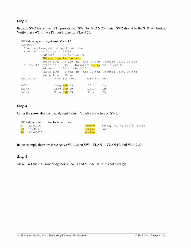
Step 3
Because SW2 has a lower STP priority than SW1 for VLAN 20, switch SW2 should be the STP root bridge.Verify that SW2 is the STP root bridge for VLAN 20.
SW2#show spanning-tree vlan 20VLAN0020 Spanning tree enabled protocol ieee Root ID Priority 24596 Address 001e.147c.6f00 This bridge is the root Hello Time 2 sec Max Age 20 sec Forward Delay 15 sec Bridge ID Priority 24596 (priority 24576 sys-id-ext 20) Address 001e.147c.6f00 Hello Time 2 sec Max Age 20 sec Forward Delay 15 sec Aging Time 300 secInterface Role Sts Cost Prio.Nbr Type------------------- ---- --- --------- -------- --------------------------------Fa0/1 Desg FWD 19 128.1 P2pFa0/3 Desg FWD 19 128.3 P2pFa0/4 Desg FWD 19 128.4 P2p
Step 4
Using the show vlan command, verify which VLANs are active on SW1.
SW1#show vlan | include active1 default active Fa0/2, Fa0/4, Fa0/5, Fa0/610 VLAN0010 active Fa0/120 VLAN0020 active
In the example there are three active VLANs on SW1: VLAN 1, VLAN 10, and VLAN 20.
Step 5
Make SW1 the STP root bridge for VLAN 1 and VLAN 10 (if it is not already).
L-182 Interconnecting Cisco Networking Devices: Accelerated © 2013 Cisco Systems, Inc.

Step 6
Verify that SW1 is now the STP root bridge for VLANs 1 and 10.
SW1#show spanning-tree vlan 1VLAN0001 Spanning tree enabled protocol ieee Root ID Priority 24577 Address 001e.145e.4980 This bridge is the root Hello Time 2 sec Max Age 20 sec Forward Delay 15 sec Bridge ID Priority 24577 (priority 24576 sys-id-ext 1) Address 001e.145e.4980 Hello Time 2 sec Max Age 20 sec Forward Delay 15 sec Aging Time 300 secInterface Role Sts Cost Prio.Nbr Type------------------- ---- --- --------- -------- --------------------------------Fa0/3 Desg FWD 19 128.3 P2pFa0/4 Desg FWD 19 128.4 P2pFa0/13 Desg FWD 19 128.13 P2pSW1#show spanning-tree vlan 10VLAN0010 Spanning tree enabled protocol ieee Root ID Priority 24586 Address 001e.145e.4980 This bridge is the root Hello Time 2 sec Max Age 20 sec Forward Delay 15 sec Bridge ID Priority 24586 (priority 24576 sys-id-ext 10) Address 001e.145e.4980 Hello Time 2 sec Max Age 20 sec Forward Delay 15 sec Aging Time 300 secInterface Role Sts Cost Prio.Nbr Type------------------- ---- --- --------- -------- --------------------------------Fa0/1 Desg FWD 19 128.1 P2pFa0/3 Desg FWD 19 128.3 P2pFa0/4 Desg FWD 19 128.4 P2pFa0/13 Desg FWD 19 128.13 P2p
Activity VerificationNo additional verification is needed in this task.
Task 3: Implement STP PortFastFirst, you will determine how long it takes for a switch port to become fully operational when a host isconnected. You will then configure a switch port connecting the host with the STP PortFast feature. Youwill again test how long it takes for the switch port to become fully operational. You will noticeimprovement in the switch port behavior.
Activity ProcedureComplete the following steps:
© 2013 Cisco Systems, Inc. Lab Guide L-183

Step 1
On SW1, shut down the FastEthernet 0/1 port. PC1 is connected to the SW1 FastEthernet 0/1 port.
In the example, there are three active VLANs on SW2: VLAN 1, VLAN 10, and VLAN 20.
Step 2
On SW1, use the debug spanning-tree events command to enable STP event debugging.
SW1#debug spanning-tree events Spanning Tree event debugging is on
STP event debugging will show you exactly how long it takes for the port to become fully operational afteryou enable the router interface.
Step 3
On SW1, enable the FastEthernet 0/1 port and examine the debugging output. Wait until the FastEthernet0/1 port on SW1 is in the forwarding state.
Aug 30 08:05:42.704: set portid: VLAN0010 Fa0/1: new port id 8001Aug 30 08:05:42.704: STP: VLAN0010 Fa0/1 -> listeningAug 30 08:05:43.115: %LINK-3-UPDOWN: Interface FastEthernet0/1, changed state to upAug 30 08:05:44.122: %LINEPROTO-5-UPDOWN: Line protocol on Interface FastEthernet0/1, changed state to upAug 30 08:05:57.711: STP: VLAN0010 Fa0/1 -> learningAug 30 08:06:12.719: STP[10]: Generating TC trap for port FastEthernet0/1Aug 30 08:06:12.719: STP: VLAN0010 sent Topology Change Notice on Fa0/3Aug 30 08:06:12.719: STP: VLAN0010 Fa0/1 -> forwardingAug 30 08:06:12.744: STP: VLAN0010 Topology Change rcvd on Fa0/1Aug 30 08:06:12.744: STP: VLAN0010 sent Topology Change Notice on Fa0/3
Note that there is approximately 30 seconds between these two events:
FastEthernet 0/1 enters the listening state at Aug 30 08:05:42.704.
FastEthernet 0/1 enters the forwarding state at Aug 30 08:06:12.719.
Step 4
On SW1, configure FastEthernet 0/1 with the STP PortFast feature.
L-184 Interconnecting Cisco Networking Devices: Accelerated © 2013 Cisco Systems, Inc.

Step 5
Perform the test again by disabling and enabling the SW1 FastEthernet 0/1 port. On SW1, examine thedebugging output.
Aug 30 08:27:42.685: STP: VLAN0010 sent Topology Change Notice on Fa0/3Aug 30 08:27:42.685: STP[10]: Generating TC trap for port FastEthernet0/1Aug 30 08:27:44.682: %LINK-3-UPDOWN: Interface FastEthernet0/1, changed state to downAug 30 08:27:45.529: set portid: VLAN0010 Fa0/1: new port id 8001Aug 30 08:27:45.529: STP: VLAN0010 Fa0/1 ->jump to forwarding from blockingAug 30 08:27:46.728: STP: VLAN0010 heard root 33274-000f.34f9.9200 on Fa0/1Aug 30 08:27:46.737: STP: VLAN0010 Topology Change rcvd on Fa0/1Aug 30 08:27:46.737: STP: VLAN0010 sent Topology Change Notice on Fa0/3Aug 30 08:27:47.525: %LINK-3-UPDOWN: Interface FastEthernet0/1, changed state to up
Note that after you enabled the STP PortFast feature, it takes less than a second for the port to become fullyoperational. STP puts the port immediately into the forwarding state.
Step 6
On SW1, use the no debug all command to disable all debugging.
SW1#no debug allAll possible debugging has been turned off
Activity VerificationNo additional verification is needed in this task.
Task 4: Implement STP BPDU GuardIn this task, you will enable the STP BPDU guard feature. For testing purposes, you will enable the featureon a port that is connected to another switch. When the switch receives a BPDU from another switch, theport enters the down state, with an error-disable message.
Activity ProcedureComplete the following steps:
Step 1
On SW1, use the debug spanning-tree events command to enable STP event debugging.
SW1#debug spanning-tree events Spanning Tree event debugging is on
The STP event debugging will show you what happens when STP BPDU guard is enabled on the port and aBPDU is received.
© 2013 Cisco Systems, Inc. Lab Guide L-185

Step 2
On SW1, enable the STP BPDU guard feature on the FastEthernet 0/3 port and examine the debuggingoutput. The FastEthernet 0/3 port connects to SW2.
Aug 30 09:12:29.875: %SPANTREE-2-BLOCK_BPDUGUARD: Received BPDU on port Fa0/3 with BPDU Guard enabled. Disabling port.Aug 30 09:12:29.875: %PM-4-ERR_DISABLE: bpduguard error detected on Fa0/3, putting Fa0/3 in err-disable stateAug 30 09:12:30.882: %LINEPROTO-5-UPDOWN: Line protocol on Interface FastEthernet0/3, changed state to downAug 30 09:12:31.888: %LINK-3-UPDOWN: Interface FastEthernet0/3, changed state to down
Note that the BPDU guard feature immediately disables the port because a BPDU was received from SW2.
Step 3
On SW1, use the show interfaces FastEthernet 0/3 command to verify that the FastEthernet 0/3 port isdown.
SW1#show interfaces FastEthernet 0/3 FastEthernet0/3 is down, line protocol is down (err-disabled) Hardware is Fast Ethernet, address is 001e.147c.bd03 (bia 001e.147c.bd03) MTU 1500 bytes, BW 10000 Kbit/sec, DLY 1000 usec, reliability 255/255, txload 1/255, rxload 1/255<output omitted>
Note the message “err-disabled” next to “line protocol is down,” which means that the port was disabled bythe BPDU guard feature.
Step 4
To make the FastEthernet 0/3 port operational on SW1, disable the STP BPDU guard feature. You alsoneed to disable and enable the port.
Step 5
On SW1, use the show interfaces FastEthernet 0/3 command to verify that the FastEthernet 0/3 port is upand operational.
SW1#show interfaces FastEthernet 0/3FastEthernet0/3 is up, line protocol is up (connected) Hardware is Fast Ethernet, address is 001e.147c.bd03 (bia 001e.147c.bd03) MTU 1500 bytes, BW 100000 Kbit/sec, DLY 100 usec, reliability 255/255, txload 1/255, rxload 1/255<output omitted>
L-186 Interconnecting Cisco Networking Devices: Accelerated © 2013 Cisco Systems, Inc.

Step 6
On SW1, use the no debug all command to disable all debugging.
SW1#no debug allAll possible debugging has been turned off
Step 7
Save the configurations on the switches SW1 and SW2.
Activity VerificationNo additional verification is needed in this task.
© 2013 Cisco Systems, Inc. Lab Guide L-187

L-188 Interconnecting Cisco Networking Devices: Accelerated © 2013 Cisco Systems, Inc.

Lab 5-5: ConfiguringEtherChannel
Activity OverviewObjectivesIn this lab, you will become familiar with EtherChannel technology. When you have completed thisactivity, you will be able to meet these objectives:
Configure EtherChannel
Verify EtherChannel redundancy
Visual ObjectiveThe figure illustrates what you will accomplish in this activity.

Visual Objective for Lab 5-5: ConfiguringEtherChannel
Internet
WAN
Server
PC1
PC2
SW1
SW2
Branch
HQ
© 2013 Cisco Systems, Inc.
Detailed Visual Objective
PC1
PC2
SW1
SW2
Branch
Fa0/3 Fa0/4
Fa0/3 Fa0/4
Configure
EtherChannel
Test
EtherChannel
Redundancy
© 2013 Cisco Systems, Inc.
Required ResourcesNo additional resources are required for this lab.
Command ListThe table describes the commands that are used in this activity. The commands are listed in alphabeticalorder so that you can easily locate the information that you need. Refer to this list if you need configurationcommand assistance during the lab activity.
L-190 Interconnecting Cisco Networking Devices: Accelerated © 2013 Cisco Systems, Inc.

CommandsCommand Description.
channel-group channel_id mode active Configures an interface or interfaces as EtherChannel bundlemembers using LACP in active mode.
configure terminal Enters global configuration mode.
interface interface Enters interface configuration mode.
interface range interface_range Enters interface range configuration mode.
show etherchannel port-channel Displays port channel interface information.
show interfaces interface Displays interface status and statistics.
show spanning-tree vlan vlan_id Verifies spanning tree configuration for a VLAN.
shutdown Disables an interface.
Job AidsThese job aids are available to help you complete the lab activity.
The table shows the hardware that is used in the lab and the operating system that is running on the devices.
Device Hardware Operating System
Branch Cisco 2901 Integrated Services Router c2900-universalk9-mz.SPA.152-4.M1
HQ Cisco 2901 Integrated Services Router c2900-universalk9-mz.SPA.152-4.M1
SW1 Catalyst 2960 Series Switch c2960-lanbasek9-mz.150-1.SE3
SW2 Catalyst 2960 Series Switch c2960-lanlitek9-mz.150-1.SE3
PC1 Any PC Microsoft Windows 7
PC2 Any PC Microsoft Windows 7
The table shows the usernames and passwords that are used to access the equipment in this lab.
Device Username Password
PC1 Administrator admin
PC2 Administrator admin
Topology and IP Addressing
Devices are connected with Ethernet and serial connections. The figure illustrates the interfaceidentification and IP addresses that are used in this lab setup.
© 2013 Cisco Systems, Inc. Lab Guide L-191

Topology and IP Addressing
Internet
WAN
Server
PC1
PC2
SW1
SW2
Branch
HQ
Fa0/1
Fa0/1
Gi0/0
Fa0/13
Fa0/3 Fa0/4
Fa0/3 Fa0/4
Gi0/1
209.165.201.1
Gi0/1
209.165.201.2
S0/0/0
192.168.1.2
S0/0/0
192.168.1.1
10.1.10.100
10.1.20.100
10.1.1.11
10.1.1.12
VLAN 1—10.1.1.1
VLAN 10—10.1.10.1
VLAN 20—10.1.20.1
172.16.1.100
© 2013 Cisco Systems, Inc.
The table shows the interface identification and IP addresses that are used in this lab setup.
Device Interface IP Address/Subnet Mask
Branch GigabitEthernet0/0.1 (VLAN1) 10.1.1.1/24
Branch GigabitEthernet0/0.10 (VLAN10) 10.1.10.1/24
Branch GigabitEthernet0/0.20 (VLAN20) 10.1.20.1/24
Branch GigabitEthernet0/1 209.165.201.1/27
Branch Serial0/0/0 192.168.1.1/24
HQ GigabitEthernet0/1 209.165.201.2/27
HQ Serial0/0/0 192.168.1.2/24
HQ Loopback0 172.16.1.100/24
SW1 VLAN1 10.1.1.11/24
SW2 VLAN1 10.1.1.12/24
PC1 Ethernet adapter local area connection 10.1.10.100/24
PC2 Ethernet adapter local area connection 10.1.20.100/24
Trunk and VLAN Setup
Three VLANs are configured on the switches. VLAN 1 is used for switch management, VLAN 10 is usedto connect PC1, and VLAN 20 is used to connect PC2. A trunk is configured on each of the two linksbetween switches SW1 and SW2. SW1 and the Branch router are connected by a single trunk link. Thefigure illustrates the trunk and VLAN setup.
L-192 Interconnecting Cisco Networking Devices: Accelerated © 2013 Cisco Systems, Inc.

Trunk and VLAN Setup
VLAN1
VLAN10
VLAN20
PC1
PC2
SW1
SW2
Branch
Trunk
© 2013 Cisco Systems, Inc.
Task 1: Configure EtherChannelIn this task, you will first verify that STP blocked one of the ports between the switches. Then you willconfigure an EtherChannel bundle between the SW1 and SW2 switches to use both available interfaces toincrease bandwidth and provide redundancy between the switches.
Activity ProcedureComplete the following steps:
© 2013 Cisco Systems, Inc. Lab Guide L-193

Step 1
On SW2, verify the spanning-tree configuration for VLAN 10. Your output should look like this example:
SW2#show spanning-tree vlan 10VLAN0010 Spanning tree enabled protocol ieee Root ID Priority 24586 Address 001e.147c.6f00 Cost 19 Port 3 (FastEthernet0/3) Hello Time 2 sec Max Age 20 sec Forward Delay 15 sec Bridge ID Priority 32778 (priority 32768 sys-id-ext 10) Address 001e.145e.4980 Hello Time 2 sec Max Age 20 sec Forward Delay 15 sec Aging Time 300 secInterface Role Sts Cost Prio.Nbr Type------------------- ---- --- --------- -------- --------------------------------Fa0/3 Root FWD 19 128.3 P2pFa0/4 Altn BLK 19 128.4 P2p
You should see that FastEthernet0/3 is in the forwarding state and FastEthernet0/4 is in the blocking state.Thus, only one link between the switches is in a forwarding state, because of STP. In the next step, you willbundle both interfaces into an EtherChannel to use both interfaces to increase bandwidth and provideredundancy.
Step 2
On SW1, configure FastEthernet0/3 and FastEthernet0/4 interfaces as EtherChannel members. Use 1 as theport channel identifier and configure LACP in the active mode.
Step 3
On SW2, configure the FastEthernet0/3 and FastEthernet0/4 interfaces as EtherChannel members. Use 1 asthe port channel identifier and configure LACP in the active mode.
Activity VerificationYou have completed this task when you attain these results:
L-194 Interconnecting Cisco Networking Devices: Accelerated © 2013 Cisco Systems, Inc.

Step 1
On SW2, verify the spanning-tree configuration for VLAN 10.
SW2#show spanning-tree vlan 10VLAN0010 Spanning tree enabled protocol ieee Root ID Priority 24586 Address 001e.147c.6f00 Cost 12 Port 64 (Port-channel1) Hello Time 2 sec Max Age 20 sec Forward Delay 15 sec Bridge ID Priority 32778 (priority 32768 sys-id-ext 10) Address 001e.145e.4980 Hello Time 2 sec Max Age 20 sec Forward Delay 15 sec Aging Time 300 secInterface Role Sts Cost Prio.Nbr Type------------------- ---- --- --------- -------- --------------------------------Po1 Root FWD 12 128.64 P2p
Before you had ports FastEthernet 0/3 and 0/4 listed, now there is one single interface, Port-channel 1, thatbundled the two interfaces.
Step 2
On SW1, verify the state of the port channel interface:
SW1#show interfaces port-channel 1Port-channel1 is up, line protocol is up (connected)<output omitted>
Step 3
On SW2, verify the state of the port channel interface:
SW2#show interfaces port-channel 1Port-channel1 is up, line protocol is up (connected) <output omitted>
© 2013 Cisco Systems, Inc. Lab Guide L-195

Step 4
On SW1, display the port channel interface information:
SW1#show etherchannel port-channel Channel-group listing: ----------------------Group: 1 ---------- Port-channels in the group: ---------------------------Port-channel: Po1 (Primary Aggregator)------------Age of the Port-channel = 0d:00h:29m:43sLogical slot/port = 2/1 Number of ports = 2HotStandBy port = null Port state = Port-channel Ag-Inuse Protocol = LACPPort security = DisabledPorts in the Port-channel: Index Load Port EC state No of bits------+------+------+------------------+----------- 0 00 Fa0/3 Active 0 0 00 Fa0/4 Active 0Time since last port bundled: 0d:00h:29m:39s Fa0/4
Step 5
On SW2, display the port channel interface information:
SW2#show etherchannel port-channel Channel-group listing: ----------------------Group: 1 ---------- Port-channels in the group: ---------------------------Port-channel: Po1 (Primary Aggregator)------------Age of the Port-channel = 0d:00h:31m:06sLogical slot/port = 2/1 Number of ports = 2HotStandBy port = null Port state = Port-channel Ag-Inuse Protocol = LACPPort security = DisabledPorts in the Port-channel: Index Load Port EC state No of bits------+------+------+------------------+----------- 0 00 Fa0/3 Active 0 0 00 Fa0/4 Active 0Time since last port bundled: 0d:00h:30m:41s Fa0/4
L-196 Interconnecting Cisco Networking Devices: Accelerated © 2013 Cisco Systems, Inc.

Step 6
On SW1, verify the spanning tree configuration for VLAN 10. You should see that the EtherChannelinterface appears as a single interface to STP.
SW1#show spanning-tree vlan 10VLAN0010 Spanning tree enabled protocol ieee Root ID Priority 10 Address 001e.145e.4980 Cost 12 Port 64 (Port-channel1) Hello Time 2 sec Max Age 20 sec Forward Delay 15 sec Bridge ID Priority 32778 (priority 32768 sys-id-ext 10) Address 001e.147c.6f00 Hello Time 2 sec Max Age 20 sec Forward Delay 15 sec Aging Time 300 secInterface Role Sts Cost Prio.Nbr Type------------------- ---- --- --------- -------- --------------------------------Fa0/1 Desg FWD 19 128.1 P2p Fa0/13 Desg FWD 19 128.13 P2p Po1 Root FWD 12 128.64 P2p
Task 2: Verify EtherChannel RedundancyIn this task, you will verify EtherChannel redundancy by shutting down one of the ports in theEtherChannel bundle. You will observe the connectivity between the PCs while shutting down the port.
Activity ProcedureComplete the following steps:
Step 1
Access PC1. Open a command prompt and trigger a continuous ping to PC2 at 10.1.20.100. Leave thecommand prompt open.
c:\>ping 10.1.20.100 -tPinging 10.1.20.100 with 32 bytes of data:Reply from 10.1.20.100: bytes=32 time=1ms TTL=127Reply from 10.1.20.100: bytes=32 time<10ms TTL=127Reply from 10.1.20.100: bytes=32 time=1ms TTL=127Reply from 10.1.20.100: bytes=32 time=1ms TTL=127<output omitted>
Step 2
Access SW1.
© 2013 Cisco Systems, Inc. Lab Guide L-197

Step 3
Shut down the FastEthernet0/3 interface. Return to the command prompt on the PC1 and observe the pings.
Were any packets lost when the interface was shut down?
Step 4
On SW1, display the port channel interface information.
SW1#show etherchannel port-channel Channel-group listing: ----------------------Group: 1 ---------- Port-channels in the group: ---------------------------Port-channel: Po1 (Primary Aggregator)------------Age of the Port-channel = 0d:00h:01m:47sLogical slot/port = 2/1 Number of ports = 1HotStandBy port = null Port state = Port-channel Ag-Inuse Protocol = LACPPort security = DisabledPorts in the Port-channel: Index Load Port EC state No of bits------+------+------+------------------+----------- 0 00 Fa0/4 Active 0 Time since last port bundled: 0d:00h:01m:11s Fa0/3Time since last port Un-bundled: 0d:00h:00m:17s Fa0/3
You should see that only one interface is in the bundle. You should also see how long ago the interface wasremoved from the EtherChannel bundle.
Step 5
Bring the FastEthernet0/3 interface back up.
L-198 Interconnecting Cisco Networking Devices: Accelerated © 2013 Cisco Systems, Inc.

Step 6
On SW1, display the port channel interface information.
SW1#show etherchannel port-channel Channel-group listing: ----------------------Group: 1 ---------- Port-channels in the group: ---------------------------Port-channel: Po1 (Primary Aggregator)------------Age of the Port-channel = 0d:00h:10m:21sLogical slot/port = 2/1 Number of ports = 2HotStandBy port = null Port state = Port-channel Ag-Inuse Protocol = LACPPort security = DisabledPorts in the Port-channel: Index Load Port EC state No of bits------+------+------+------------------+----------- 0 00 Fa0/3 Active 0 0 00 Fa0/4 Active 0Time since last port bundled: 0d:00h:00m:05s Fa0/3Time since last port Un-bundled: 0d:00h:08m:51s Fa0/3
You should see that both interfaces are in the bundle. You should also see how long ago the interface wasadded back into the EtherChannel bundle.
Step 7
Return to PC1 and interrupt the continuous ping using the Ctrl-C combination.
Step 8
Save the configurations on the switches SW1 and SW2.
Activity VerificationNo additional verification is needed in this task.
© 2013 Cisco Systems, Inc. Lab Guide L-199

L-200 Interconnecting Cisco Networking Devices: Accelerated © 2013 Cisco Systems, Inc.

Lab 6-1: Troubleshooting IPConnectivity
Activity OverviewObjectivesIn this activity, you will explore various trouble tickets related to IP connectivity, identifying the problemsand correcting them. After completing this activity, you will be able to meet these objectives:
Troubleshoot the default route
Troubleshoot an ACL problem
Troubleshoot the default gateway
Troubleshoot name resolution
Visual ObjectiveThe figure illustrates what you will accomplish in this activity.

Visual Objective for Lab 6-1: TroubleshootingIP Connectivity
Internet
WAN
Server
PC1
PC2
SW1
SW2
Branch
HQ
© 2013 Cisco Systems, Inc.
Detailed Visual Objective
Desirable Path for Telnet Session
Internet
Server
PC1 SW1
Branch
HQ
Troubleshoot the ACL. Troubleshoot the default route.
Troubleshoot the default gateway and DNS.
© 2013 Cisco Systems, Inc.
Required ResourcesNo additional resources are required for this lab.
Command ListThe table describes the commands that are used in this activity. The commands are listed in alphabeticalorder so that you can easily locate the information that you need. Refer to this list if you need assistancewith configuration or verification of Cisco IOS commands during the lab activity.
L-202 Interconnecting Cisco Networking Devices: Accelerated © 2013 Cisco Systems, Inc.

CommandsCommand Description
configure terminal Enters configuration mode.
ip access-list extended ACL-name Configures extended access list and enters extended access listconfiguration mode.
ip route network mask next-hop Configures IP static route.
permit protocol source destination eq port Adds permit statement into extended access list.
ping ip_address Verifies IP connectivity.
show interfaces interface Displays interface status and statistics.
show ip access-lists Displays IP access lists.
show ip interface Displays interface IP setup.
show ip route Displays IP routing table.
telnet ip_address [tcp_port] Uses Telnet to connect to the IP address—with an optional TCP port,it opens Telnet to a specified TCP port.
traceroute ip_address Traces IP address.
Refer to this list if you need assistance with configuration or verification of Windows commands during thelab activity.
CommandsCommand Description
cd directory Changes directory in the command prompt
ipconfig Displays interface adapter IP settings
notepad file Lunches Microsoft Notepad application and opens specified file
ping ip_address Verifies IP connectivity
tracert ip_address Traces IP address
Job AidsThese job aids are available to help you complete the lab activity.
The table shows the hardware that is used in the lab and the operating system that is running on the devices.
Device Hardware Operating System
Branch Cisco 2901 Integrated Services Router c2900-universalk9-mz.SPA.152-4.M1
HQ Cisco 2901 Integrated Services Router c2900-universalk9-mz.SPA.152-4.M1
SW1 Catalyst 2960 Series Switch c2960-lanbasek9-mz.150-1.SE3
SW2 Catalyst 2960 Series Switch c2960-lanlitek9-mz.150-1.SE3
© 2013 Cisco Systems, Inc. Lab Guide L-203

Device Hardware Operating System
PC1 Any PC Microsoft Windows 7
PC2 Any PC Microsoft Windows 7
The table shows the usernames and passwords that are used to access the equipment in this lab.
Device Username Password
PC1 Administrator admin
PC2 Administrator admin
Topology and IP Addressing
Devices are connected with Ethernet and serial connections. The figure illustrates the interfaceidentification and IP addresses that are used in this lab setup.
Topology and IP Addressing
Internet
WAN
Server
PC1
PC2
SW1
SW2
Branch
HQ
Fa0/1
Fa0/1
Gi0/0
Fa0/13
Fa0/3 Fa0/4
Fa0/3 Fa0/4
Gi0/1
209.165.201.1
Gi0/1
209.165.201.2
S0/0/0
192.168.1.2
S0/0/0
192.168.1.1
10.1.10.100
10.1.20.100
10.1.1.11
10.1.1.12
VLAN 1—10.1.1.1
VLAN 10—10.1.10.1
VLAN 20—10.1.20.1
172.16.1.100
© 2013 Cisco Systems, Inc.
The table shows the interface identification and IP addresses that are used in this lab setup.
Device Interface IP Address/Subnet Mask
Branch GigabitEthernet0/0.1 (VLAN 1) 10.1.1.1/24
Branch GigabitEthernet0/0.10 (VLAN 10) 10.1.10.1/24
Branch GigabitEthernet0/0.20 (VLAN 20) 10.1.20.1/24
Branch GigabitEthernet0/1 209.165.201.1/27
Branch Serial0/0/0 192.168.1.1/24
Branch Loopback10 10.100.100.100/32
HQ GigabitEthernet0/1 209.165.201.2/27
L-204 Interconnecting Cisco Networking Devices: Accelerated © 2013 Cisco Systems, Inc.

Device Interface IP Address/Subnet Mask
HQ Serial0/0/0 192.168.1.2/24
HQ Loopback0 172.16.1.100/24
SW1 VLAN 1 10.1.1.11/24
SW2 VLAN 1 10.1.1.12/24
PC1 Ethernet adapter local area connection 10.1.10.100/24
PC2 Ethernet adapter local area connection 10.1.20.100/24
Trunk and VLAN Setup
Three VLANs are configured on the switches. VLAN 1 is used for switch management, VLAN 10 is usedto connect PC1, and VLAN 20 is used to connect PC2. The two links between SW1 and SW2 are bondedinto an EtherChannel and a trunk is configured on it. The SW1 switch and the Branch router are connectedby a trunk link. The figure illustrates trunk and VLAN setup.
Trunk and VLAN Setup
© 2013 Cisco Systems, Inc.
Task 1: Troubleshoot the Default RouteYou have been informed that the user in VLAN 10 cannot establish a Telnet or an HTTP connection to theserver. As a network engineer, you have to troubleshoot and correct the problem. You will run your testsfrom the switch where users connect.
The senior network engineer has confirmed that the problem is not between the SW1 switch and the Branchrouter. You also found out that the name server should be resolved into IP address 172.16.1.100.Connectivity to the server is provided through the GigabitEthernet 0/1 interface on the Branch router. Thesenior network engineer configured the static IP address and default route on the Branch router while hewas looking into the issue.
© 2013 Cisco Systems, Inc. Lab Guide L-205

Activity ProcedureComplete the following steps:
Step 1
On SW1, verify that you can ping the IP address of the server (172.16.1.100).
SW1#ping 172.16.1.100Type escape sequence to abort.Sending 5, 100-byte ICMP Echos to 172.16.1.100, timeout is 2 seconds:U.U.USuccess rate is 0 percent (0/5)
The ping is not successful. From the output, you can see that the destination is unreachable and an errorPDU is received.
The table below lists the possible output characters from the ping command:
Character Description
! Each exclamation point indicates the receipt of a reply.
. Each period indicates the network server timed out while waiting for a reply.
U A destination unreachable error PDU was received.
Q Source quench (destination too busy).
M Could not fragment.
? Unknown packet type.
& Packet lifetime is exceeded.
L-206 Interconnecting Cisco Networking Devices: Accelerated © 2013 Cisco Systems, Inc.

Step 2
On SW1, perform a trace to the IP address of the server (172.16.1.100).
SW1#traceroute 172.16.1.100Type escape sequence to abort.Tracing the route to Server (172.16.1.100) 1 10.1.1.1 0 msec 8 msec 0 msec 2 10.1.1.1 !H * !H
From the traceroute command output, you can see that the host is unreachable and the last hop thatanswers is from IP 10.1.1.1. This means that there is a possible problem on the router with IP address10.1.1.1.
From the network diagram, you find out that IP address 10.1.1.1 is on the Branch router. You will continuetroubleshooting on the Branch router.
The table lists the characters that can appear in the traceroute command output.
Character Description
nn msec For each node, the round-trip time in milliseconds for the specified number of probes.
* The probe timed out.
A Administratively prohibited (for example, an access list).
Q Source quench (destination too busy).
I User interrupted test.
U Port unreachable.
H Host unreachable.
N Network unreachable.
P Protocol unreachable.
T Timeout.
? Unknown packet type.
© 2013 Cisco Systems, Inc. Lab Guide L-207

Step 3
On the Branch router, verify that interface GigabitEthernet 0/1, which connects to the Internet, isoperational.
Branch#show interfaces GigabitEthernet 0/1GigabitEthernet0/1 is up, line protocol is up Hardware is CN Gigabit Ethernet, address is 5475.d08e.9ad9 (bia 5475.d08e.9ad9) Description: Link to HQ Internet address is 209.165.201.1/27 MTU 1500 bytes, BW 100000 Kbit/sec, DLY 100 usec, reliability 255/255, txload 1/255, rxload 1/255 Encapsulation ARPA, loopback not set Keepalive set (10 sec) Full Duplex, 100Mbps, media type is RJ45 output flow-control is unsupported, input flow-control is unsupported <output omitted>
The interface is fully operational.
Step 4
On the Branch router, verify that there is a route to the server (172.16.1.100). There should be a static routeconfigured on the Branch router.
Branch#show ip route Codes: L - local, C - connected, S - static, R - RIP, M - mobile, B - BGP D - EIGRP, EX - EIGRP external, O - OSPF, IA - OSPF inter area N1 - OSPF NSSA external type 1, N2 - OSPF NSSA external type 2 E1 - OSPF external type 1, E2 - OSPF external type 2 i - IS-IS, su - IS-IS summary, L1 - IS-IS level-1, L2 - IS-IS level-2 ia - IS-IS inter area, * - candidate default, U - per-user static route o - ODR, P - periodic downloaded static route, H - NHRP, l - LISP + - replicated route, % - next hop overrideGateway of last resort is not set 10.0.0.0/8 is variably subnetted, 6 subnets, 2 masksC 10.1.1.0/24 is directly connected, GigabitEthernet0/0.1L 10.1.1.1/32 is directly connected, GigabitEthernet0/0.1C 10.1.10.0/24 is directly connected, GigabitEthernet0/0.10L 10.1.10.1/32 is directly connected, GigabitEthernet0/0.10C 10.1.20.0/24 is directly connected, GigabitEthernet0/0.20L 10.1.20.1/32 is directly connected, GigabitEthernet0/0.20 209.165.201.0/24 is variably subnetted, 2 subnets, 2 masksC 209.165.201.0/27 is directly connected, GigabitEthernet0/1L 209.165.201.1/32 is directly connected, GigabitEthernet0/1
The Branch router has no specific route to the server. Also, there is no default route configured.
L-208 Interconnecting Cisco Networking Devices: Accelerated © 2013 Cisco Systems, Inc.

Step 5
On the Branch router, configure the default route with the next-hop IP address 209.165.201.2.
Verify the routing table once again.
Branch#show ip route Codes: L - local, C - connected, S - static, R - RIP, M - mobile, B - BGP D - EIGRP, EX - EIGRP external, O - OSPF, IA - OSPF inter area N1 - OSPF NSSA external type 1, N2 - OSPF NSSA external type 2 E1 - OSPF external type 1, E2 - OSPF external type 2 i - IS-IS, su - IS-IS summary, L1 - IS-IS level-1, L2 - IS-IS level-2 ia - IS-IS inter area, * - candidate default, U - per-user static route o - ODR, P - periodic downloaded static route, H - NHRP, l - LISP + - replicated route, % - next hop overrideGateway of last resort is 209.165.201.2 to network 0.0.0.0S* 0.0.0.0/0 [1/0] via 209.165.201.2 10.0.0.0/8 is variably subnetted, 6 subnets, 2 masksC 10.1.1.0/24 is directly connected, GigabitEthernet0/0.1L 10.1.1.1/32 is directly connected, GigabitEthernet0/0.1C 10.1.10.0/24 is directly connected, GigabitEthernet0/0.10L 10.1.10.1/32 is directly connected, GigabitEthernet0/0.10C 10.1.20.0/24 is directly connected, GigabitEthernet0/0.20L 10.1.20.1/32 is directly connected, GigabitEthernet0/0.20 209.165.201.0/24 is variably subnetted, 2 subnets, 2 masksC 209.165.201.0/27 is directly connected, GigabitEthernet0/1L 209.165.201.1/32 is directly connected, GigabitEthernet0/1
The configured default route should appear as a static route, and the gateway of last resort should be shownin the routing table of the Branch router.
Activity VerificationYou have completed this task when you attain this result:
Step 1
On SW1, verify that you can ping the IP address of the server (172.16.1.100).
SW1#ping 172.16.1.100Type escape sequence to abort.Sending 5, 100-byte ICMP Echos to 172.16.1.100, timeout is 2 seconds:!!!!!Success rate is 100 percent (5/5), round-trip min/avg/max = 1/4/9 ms
The ping is successful.
Task 2: Troubleshoot an ACLIn this task, you will continue troubleshooting by checking whether the user in VLAN 10 is able to reachthe server via Telnet and HTTP. The user on PC1 should only be allowed HTTP, Telnet, traceroute, andping traffic types to and from the server at 172.16.1.100.
© 2013 Cisco Systems, Inc. Lab Guide L-209

Activity ProcedureComplete the following steps:
Step 1
On SW1, use Telnet and try to connect to 172.16.1.100 on ports 23 (Telnet) and 80 (HTTP).
SW1#telnet 172.16.1.100 23Trying 172.16.1.100, 80 ...% Destination unreachable; gateway or host downSW1#telnet 172.16.1.100 80Trying 172.16.1.100, 80 ...% Destination unreachable; gateway or host down
There is no connectivity between SW1 and the server at 172.16.1.100 through ports 23 and 80.
Step 2
On SW1, trace to the IP address of the server (172.16.1.100).
SW1#traceroute 172.16.1.100Type escape sequence to abort.Tracing the route to Server (172.16.1.100) 1 10.1.1.1 0 msec 8 msec 0 msec 2 10.1.1.1 !A * !A
From the traceroute output, you can see that packets with IP address 10.1.1.1 are administrativelyprohibited by the router. There may be an ACL that prohibits Telnet and HTTP as well. You will continuetroubleshooting on the Branch router.
Step 3
On the Branch router, examine the interfaces to see if any ACLs are used.
Branch#show ip interface | include GigabitEthernet|access listGigabitEthernet0/0 is up, line protocol is upGigabitEthernet0/0.1 is up, line protocol is up Outgoing access list is not set Inbound access list is not setGigabitEthernet0/0.10 is up, line protocol is up Outgoing access list is not set Inbound access list is not setGigabitEthernet0/0.20 is up, line protocol is up Outgoing access list is not set Inbound access list is not setGigabitEthernet0/1 is up, line protocol is up Outgoing access list is Outbound-ACL Inbound access list is not set
Notice that there is an ACL, Outbound-ACL, set as outgoing on the GigabitEthernet0/1 interface.
L-210 Interconnecting Cisco Networking Devices: Accelerated © 2013 Cisco Systems, Inc.

Step 4
On the Branch router, examine the Outbound-ACL ACL.
Branch#show ip access-lists Outbound-ACLExtended IP access list Outbound-ACL 10 permit icmp any any 20 permit tcp any any eq ftp 30 permit tcp any any eq ftp-data
The ACL that is displayed is permitting all ICMP traffic, but from TCP, only ports FTP and FTP-DATA arepermitted. All other protocols and ports are denied. To allow users to access the server via Telnet andHTTP, you need to adjust the ACL entries on the Branch router.
Step 5
On the Branch router, adjust Outbound-ACL to permit Telnet (23) and HTTP (80) ports in TCP.
Step 6
From SW1, verify the establishment of Telnet and HTTP sessions to the server (172.16.1.100).
SW1#telnet 172.16.1.100Trying 172.16.1.100 ... OpenHQ>exit[Connection to 172.16.1.100 closed by foreign host]SW1#
SW1#telnet 172.16.1.100 80Trying 172.16.1.100, 80 ... Openexit
Telnet connection to standard port 23 is successful, as well as Telnet connection to HTTP port 80 (indicatedby the "... Open" response). Now it is very likely that the user in VLAN 10 will be able to reach the servervia both protocols.
© 2013 Cisco Systems, Inc. Lab Guide L-211

Step 7
Issue a traceroute command from SW1 to 172.16.1.100. Response should still not be successful.
Which configuration step is missing to have a successful traceroute response?
SW1#traceroute 172.16.1.100Type escape sequence to abort.Tracing the route to 172.16.1.100 1 10.1.1.1 0 msec 8 msec 0 msec 2 10.1.1.1 !A * !A
Activity VerificationNo additional verification is needed in this task.
Task 3: Troubleshoot the Default Gateway andName Resolution SettingsIn this task, you will troubleshoot the default gateway and name resolution setup on PC1, which isconnected to VLAN 10.
From the network diagram, you learned that the default gateway for VLAN 10 is 10.1.10.1. Additionally,the senior network engineer has confirmed that no DNS server is set in the domain. Users will need to setlocal name resolution mapping on their PCs to be able to connect to the server without specifying an IPaddress.
Activity ProcedureComplete the following steps:
Step 1
On PC1, open the command prompt and verify that a ping to the server is not successful.
C:\>ping ServerPing request could not find host Server. Please check the name and try again.C:\>
PC1 cannot resolve the name server into IP address 172.16.1.100.
L-212 Interconnecting Cisco Networking Devices: Accelerated © 2013 Cisco Systems, Inc.

Step 2
On PC1, use the command prompt and browse to the C:\Windows\System32\drivers\etc directory. Open theHosts file with the Notepad application.
C:\>cd C:\Windows\System32\drivers\etcC:\Windows\System32\drivers\etc>notepad hosts
The Notepad application opens the Hosts file.
Step 3
On the PC1 Hosts file, enter the mapping of the IP address 172.16.1.100 to the name server.
172.16.1.100 Server
Save the Hosts file as shown.
PC1 now has a local DNS entry to resolve the name server into IP address 172.16.1.100.
© 2013 Cisco Systems, Inc. Lab Guide L-213

Step 4
On PC1, from the command prompt, use the tracert command to locate the problem.
C:\Windows\System32\drivers\etc>tracert ServerTracing route to Server [172.16.1.100]over a maximum of 30 hops: 1 Windows7 [10.1.10.100] reports: Destination host unreachable.Trace complete.C:\Windows\System32\drivers\etc>
From the output, you can see that PC1 is not able to find the destination. It may be a problem in the localroute on PC1.
Step 5
On PC1, use the ipconfig command to verify that the default gateway is correctly set.
C:\Windows\System32\drivers\etc>ipconfigWindows IP ConfigurationEthernet adapter LAB: Connection-specific DNS Suffix . : Link-local IPv6 Address . . . . . : fe80::dc6d:98e9:82b7:d637%13 IPv4 Address. . . . . . . . . . . : 10.1.10.100 Subnet Mask . . . . . . . . . . . : 255.255.255.0 Default Gateway . . . . . . . . . : 10.1.10.10<output omitted>
The default gateway is not correctly set. The default gateway IP address should be 10.1.10.1.
L-214 Interconnecting Cisco Networking Devices: Accelerated © 2013 Cisco Systems, Inc.

Step 6
On PC1, change the default gateway from 10.1.10.10 to 10.1.10.1 on the Ethernet adapter that connects toSW1.
To change the default gateway on PC1, right-click to the Network icon in the Task menu and choose theOpen Network and Sharing Center option.
In the Network and Sharing Center window, choose Change Adapter Settings from the left menu.
Right-click the LAN adapter and choose Properties.
The LAN Properties window opens. Choose Internet Protocol version 4 (TCP/IPv4) and clickProperties.
© 2013 Cisco Systems, Inc. Lab Guide L-215

Change the default gateway from 10.1.10.10 to 10.1.10.1 and click OK.
L-216 Interconnecting Cisco Networking Devices: Accelerated © 2013 Cisco Systems, Inc.

Click OK in the Properties window. You have changed the default gateway on PC1.
Step 7
Save the changes you made on the Branch router.
Activity VerificationYou have completed this task when you attain this result:
© 2013 Cisco Systems, Inc. Lab Guide L-217

Step 1
On PC1, open the command prompt and verify that the ping to the server is successful.
C:\Windows\System32\drivers\etc>ping ServerPinging Server [172.16.1.100] with 32 bytes of data:Reply from 172.16.1.100: bytes=32 time=2ms TTL=254Reply from 172.16.1.100: bytes=32 time=1ms TTL=254Reply from 172.16.1.100: bytes=32 time=1ms TTL=254Reply from 172.16.1.100: bytes=32 time=1ms TTL=254Ping statistics for 172.16.1.100: Packets: Sent = 4, Received = 4, Lost = 0 (0% loss),Approximate round trip times in milli-seconds: Minimum = 1ms, Maximum = 2ms, Average = 1msC:\Windows\System32\drivers\etc>
The ping to the server should be successful.
Step 2
On PC1, use the PuTTY application and establish a Telnet connection to the server.
Establishment of a Telnet session to the server should be successful.
L-218 Interconnecting Cisco Networking Devices: Accelerated © 2013 Cisco Systems, Inc.

Step 3
Access PC1. Open Internet Explorer and try to connect to the server. If you are prompted for credentials,enter ccna as the username and cisco as the password.
You should be successful in establishing the HTTP session.
© 2013 Cisco Systems, Inc. Lab Guide L-219

L-220 Interconnecting Cisco Networking Devices: Accelerated © 2013 Cisco Systems, Inc.

Lab 7-1: Configuring andTroubleshooting a SerialConnection
Activity OverviewObjectivesIn this activity, you will identify and correct connectivity problems that are caused by misconfigured PPPencapsulation. Then, you will change the encapsulation from PPP to HDLC. After you have completed thisactivity, you will be able to meet these objectives:
Troubleshoot PPP encapsulation
Configure and verify HDLC encapsulation
Visual ObjectiveThe figure illustrates what you will accomplish in this activity.

Visual Objective for Lab 7-1: Configuring andTroubleshooting a Serial Connection
Internet
WAN
Server
PC1
PC2
SW1
SW2
Branch
HQ
© 2013 Cisco Systems, Inc.
Detailed Visual Objective
© 2013 Cisco Systems, Inc.
Required ResourcesNo additional resources are required for this lab.
Command ListThe table describes the commands that are used in this activity. The commands are listed in alphabeticalorder so that you can easily locate the information that you need. Refer to this list if you need assistancewith Cisco IOS configuration or verification commands during the lab activity.
L-222 Interconnecting Cisco Networking Devices: Accelerated © 2013 Cisco Systems, Inc.

CommandsCommand Description
configure terminal Enters configuration mode
debug ppp authentication Enables PPP authentication debugging
debug ppp negotiation Enables PPP negotiation debugging
disconnect line Disconnects the Telnet session to the remote host
encapsulation hdlc Enables HDLC encapsulation on the serial interface
interface interface Enters interface configuration mode
ping destination_address Pings the specified IP address
ppp authentication chap Enables CHAP PPP authentication on the serial interface
show interface interface Displays interface setup and statistics
show ip interface brief Displays a brief interface status
show running-config Displays the running configuration
no debug all Disables all debugging
[no] shutdown Enables or disables an interface
telnet ip_address Connects via Telnet to the specified IP address
username username passwordpassword
Configures a user on the router
Job AidsThese job aids are available to help you complete the lab activity.
The table shows the hardware that is used in the lab and the operating system that is running on the devices.
Device Hardware Operating System
Branch Cisco 2901 Integrated Services Router c2900-universalk9-mz.SPA.152-4.M4
HQ Cisco 2901 Integrated Services Router c2900-universalk9-mz.SPA.152-4.M4
SW1 Catalyst 2960 Series Switch c2960-lanbasek9-mz.150-1.SE3
SW2 Catalyst 2960 Series Switch c2960-lanlitek9-mz.150-1.SE3
PC1 Any PC Microsoft Windows 7
PC2 Any PC Microsoft Windows 7
The table shows the usernames and passwords that are used to access the equipment in this lab.
Device Username Password
PC1 Administrator admin
PC2 Administrator admin
© 2013 Cisco Systems, Inc. Lab Guide L-223

Topology and IP Addressing
Devices are connected with Ethernet and serial connections. The figure illustrates the interfaceidentification and IP addresses that are used in this lab setup.
Topology and IP Addressing
Internet
WAN
Server
PC1
PC2
SW1
SW2
Branch
HQ
Fa0/1
Fa0/1
Gi0/0
Fa0/13
Fa0/3 Fa0/4
Fa0/3 Fa0/4
Gi0/1
209.165.201.1
Gi0/1
209.165.201.2
S0/0/0
192.168.1.2
S0/0/0
192.168.1.1
10.1.10.100
10.1.20.100
10.1.1.11
10.1.1.12
VLAN 1—10.1.1.1
VLAN 10—10.1.10.1
VLAN 20—10.1.20.1
172.16.1.100
© 2013 Cisco Systems, Inc.
The table shows the interface identification and IP addresses that are used in this lab setup.
Device Interface IP Address/Subnet Mask
Branch GigabitEthernet0/0.1 (VLAN 1) 10.1.1.1/24
Branch GigabitEthernet0/0.10 (VLAN 10) 10.1.10.1/24
Branch GigabitEthernet0/0.20 (VLAN 20) 10.1.20.1/24
Branch GigabitEthernet0/1 209.165.201.1/27
Branch Serial0/0/0 192.168.1.1/24
Branch Loopback10 10.100.100.100/32
HQ GigabitEthernet0/1 209.165.201.2/27
HQ Serial0/0/0 192.168.1.2/24
HQ Loopback0 172.16.1.100/24
SW1 VLAN 1 10.1.1.11/24
SW2 VLAN 1 10.1.1.12/24
PC1 Ethernet adapter local area connection 10.1.10.100/24
PC2 Ethernet adapter local area connection 10.1.20.100/24
L-224 Interconnecting Cisco Networking Devices: Accelerated © 2013 Cisco Systems, Inc.

Trunk and VLAN Setup
Three VLANs are configured on the switches. VLAN 1 is used for switch management, VLAN 10 is usedto connect PC1, and VLAN 20 is used to connect PC2. The two links between SW1 and SW2 are bondedinto an EtherChannel and a trunk is configured on it. The SW1 switch and the Branch router are connectedby a trunk link. The figure illustrates trunk and VLAN setup.
Trunk and VLAN Setup
© 2013 Cisco Systems, Inc.
Task 1: Troubleshoot PPPIn this task, you will troubleshoot PPP encapsulation on the serial link between the Branch and HQ routers.
The serial interfaces on the Branch and HQ routers were both configured by your colleague. He configuredthem with an IP address (look at the job aids), enabled them, and configured them with PPP encapsulationusing CHAP authentication (username "ccna" and password "cisco"). However, the link is not functional.You have been instructed to troubleshoot this connection.
Activity ProcedureComplete the following steps:
© 2013 Cisco Systems, Inc. Lab Guide L-225

Step 1
On the Branch router, verify that the first serial interface is operational.
Branch#show ip interface briefInterface IP-Address OK? Method Status ProtocolGigabitEthernet0/0 unassigned YES NVRAM up upGigabitEthernet0/0.1 10.1.1.1 YES manual up upGigabitEthernet0/0.10 10.1.10.1 YES manual up upGigabitEthernet0/0.20 10.1.20.1 YES manual up upGigabitEthernet0/1 209.165.201.1 YES manual administratively down downSerial0/0/0 192.168.1.1 YES manual up down<output omitted>
The status of the Serial 0/0/0 interface is up, but the protocol is down.
Step 2
On the Branch router, verify the encapsulation of the first serial interface.
Branch#show interfaces Serial 0/0/0Serial0/0/0 is up, line protocol is down Hardware is GT96K Serial Description: Link to HQ Internet address is 192.168.1.1/24 MTU 1500 bytes, BW 1544 Kbit/sec, DLY 20000 usec, reliability 255/255, txload 1/255, rxload 1/255 Encapsulation PPP, LCP Closed, loopback not set Keepalive set (10 sec) CRC checking enabled Last input 00:00:01, output 00:00:01, output hang never Last clearing of "show interface" counters 02:04:40 Input queue: 0/75/0/0 (size/max/drops/flushes); Total output drops: 0 Queueing strategy: weighted fair Output queue: 0/1000/64/0 (size/max total/threshold/drops) Conversations 0/1/256 (active/max active/max total) Reserved Conversations 0/0 (allocated/max allocated) Available Bandwidth 1158 kilobits/sec<output omitted>
Encapsulation on the Serial 0/0/0 interface is correctly set to PPP. However, the status of the LCP will beeither Closed, ACKsent, or REQsent, but not Open.
L-226 Interconnecting Cisco Networking Devices: Accelerated © 2013 Cisco Systems, Inc.

Step 3
On the Branch router, determine the PPP authentication method that is used.
Branch#show running-config interface Serial 0/0/0Building configuration...Current configuration : 206 bytes!interface Serial0/0/0 description Link to HQ ip address 192.168.1.1 255.255.255.0 encapsulation ppp ppp authentication papendBranch#
The PPP authentication method is PAP.
Step 4
On the Branch router, enter the debug ppp negotiation command and observe the output.
Notice that one end (Branch) of the serial connection is configured with PAP type authentication, and theother end (HQ) is configured with CHAP.
Turn off all debugging on the Branch router.
Branch#debug ppp negotiationPPP protocol negotiation debugging is onBranch#Dec 3 14:30:18.383: Se0/0/0 LCP: O CONFACK [REQsent] id 1 len 15Dec 3 14:30:18.383: Se0/0/0 LCP: AuthProto CHAP (0x0305C22305)Dec 3 14:30:18.383: Se0/0/0 LCP: MagicNumber 0x9967C432 (0x05069967C432)Dec 3 14:30:18.383: Se0/0/0 LCP: Event[Receive ConfReq+] State[REQsent to ACKsent]Branch#Dec 3 14:30:18.387: Se0/0/0 LCP: O CONFREQ [ACKsent] id 16 len 14Dec 3 14:30:18.387: Se0/0/0 LCP: AuthProto PAP (0x0304C023)Dec 3 14:30:18.387: Se0/0/0 LCP: MagicNumber 0x995A9970 (0x0506995A9970)Branch#no debug all
Step 5
On the Branch router, change the PPP authentication method on the Serial 0/0/0 interface from PAP toCHAP. This way, the authentication types will match.
Step 6
On the Branch router, enable PPP authentication debugging using the debug ppp authenticationcommand.
© 2013 Cisco Systems, Inc. Lab Guide L-227

Step 7
The debug shows PPP authentication messages. Observe that authentication is not successful.
*Oct 24 11:53:29.731: Se0/0/0 PPP: Using default call direction*Oct 24 11:53:29.731: Se0/0/0 PPP: Treating connection as a dedicated line*Oct 24 11:53:29.731: Se0/0/0 PPP: Session handle[750000B1] Session id[177]*Oct 24 11:53:29.771: Se0/0/0 CHAP: O CHALLENGE id 1 len 27 from "Branch"*Oct 24 11:53:29.779: Se0/0/0 CHAP: I CHALLENGE id 1 len 23 from "HQ"*Oct 24 11:53:29.779: Se0/0/0 PPP: Sent CHAP SENDAUTH Request*Oct 24 11:53:29.783: Se0/0/0 PPP: Received SENDAUTH Response PASS*Oct 24 11:53:29.783: Se0/0/0 CHAP: Using hostname from configured hostname*Oct 24 11:53:29.783: Se0/0/0 CHAP: Using password from AAA*Oct 24 11:53:29.783: Se0/0/0 CHAP: O RESPONSE id 1 len 27 from "Branch"*Oct 24 11:53:29.791: Se0/0/0 CHAP: I RESPONSE id 1 len 23 from "HQ"*Oct 24 11:53:29.791: Se0/0/0 PPP: Sent CHAP LOGIN Request*Oct 24 11:53:29.795: Se0/0/0 PPP: Received LOGIN Response FAIL*Oct 24 11:53:29.795: Se0/0/0 CHAP: O FAILURE id 1 len 25 msg is "Authentication failed"
Step 8
The Serial 0/0/0 interface CHAP password should be “cisco.” Examine the configuration on the Branchrouter.
Branch#show running-config | include usernameusername HQ password 0 CiscoBranch#
Observe that the password for user HQ is wrong. A capital letter is used.
Step 9
On the Branch router, change the password for user HQ to “cisco.”
L-228 Interconnecting Cisco Networking Devices: Accelerated © 2013 Cisco Systems, Inc.
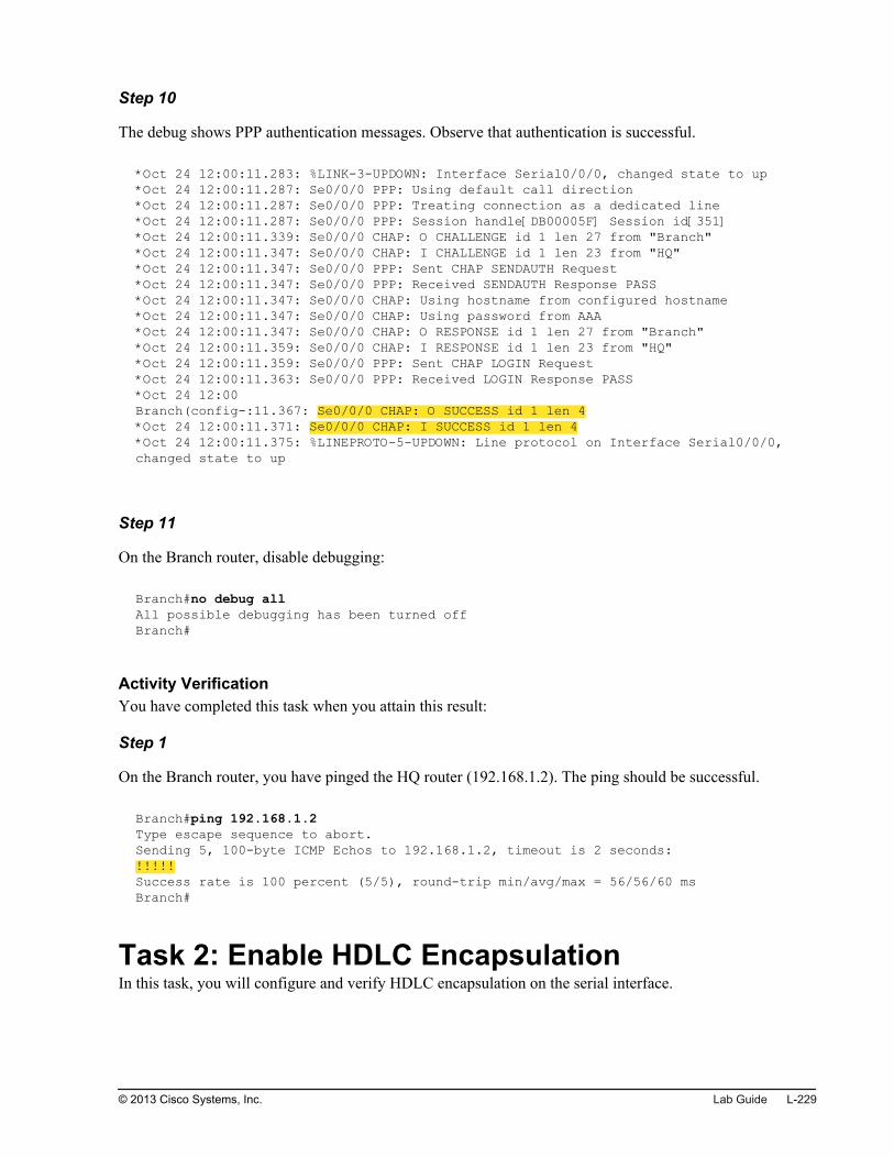
Step 10
The debug shows PPP authentication messages. Observe that authentication is successful.
*Oct 24 12:00:11.283: %LINK-3-UPDOWN: Interface Serial0/0/0, changed state to up*Oct 24 12:00:11.287: Se0/0/0 PPP: Using default call direction*Oct 24 12:00:11.287: Se0/0/0 PPP: Treating connection as a dedicated line*Oct 24 12:00:11.287: Se0/0/0 PPP: Session handle[DB00005F] Session id[351]*Oct 24 12:00:11.339: Se0/0/0 CHAP: O CHALLENGE id 1 len 27 from "Branch"*Oct 24 12:00:11.347: Se0/0/0 CHAP: I CHALLENGE id 1 len 23 from "HQ"*Oct 24 12:00:11.347: Se0/0/0 PPP: Sent CHAP SENDAUTH Request*Oct 24 12:00:11.347: Se0/0/0 PPP: Received SENDAUTH Response PASS*Oct 24 12:00:11.347: Se0/0/0 CHAP: Using hostname from configured hostname*Oct 24 12:00:11.347: Se0/0/0 CHAP: Using password from AAA*Oct 24 12:00:11.347: Se0/0/0 CHAP: O RESPONSE id 1 len 27 from "Branch"*Oct 24 12:00:11.359: Se0/0/0 CHAP: I RESPONSE id 1 len 23 from "HQ"*Oct 24 12:00:11.359: Se0/0/0 PPP: Sent CHAP LOGIN Request*Oct 24 12:00:11.363: Se0/0/0 PPP: Received LOGIN Response PASS*Oct 24 12:00Branch(config-:11.367: Se0/0/0 CHAP: O SUCCESS id 1 len 4*Oct 24 12:00:11.371: Se0/0/0 CHAP: I SUCCESS id 1 len 4*Oct 24 12:00:11.375: %LINEPROTO-5-UPDOWN: Line protocol on Interface Serial0/0/0, changed state to up
Step 11
On the Branch router, disable debugging:
Branch#no debug allAll possible debugging has been turned offBranch#
Activity VerificationYou have completed this task when you attain this result:
Step 1
On the Branch router, you have pinged the HQ router (192.168.1.2). The ping should be successful.
Branch#ping 192.168.1.2 Type escape sequence to abort.Sending 5, 100-byte ICMP Echos to 192.168.1.2, timeout is 2 seconds:!!!!!Success rate is 100 percent (5/5), round-trip min/avg/max = 56/56/60 msBranch#
Task 2: Enable HDLC EncapsulationIn this task, you will configure and verify HDLC encapsulation on the serial interface.
© 2013 Cisco Systems, Inc. Lab Guide L-229

Because you do not have console access to the HQ router, you will use Telnet to connect to the HQ routerand change the serial interface encapsulation on the HQ router first. The serial link will go down, and youwill lose the Telnet connection to the HQ router. Then you will change the serial interface encapsulation onthe Branch router, and the link should come up again.
Activity ProcedureComplete the following steps:
Step 1
From the Branch router, use Telnet to connect to the HQ router (192.168.1.2).
Branch#telnet 192.168.1.2Trying 192.168.1.2 ... OpenHQ#
Step 2
On the HQ router, change the encapsulation on the Serial 0/0/0 interface to HDLC.
You will lose Telnet connectivity to the HQ router. Return to the Branch router by pressing Ctrl-Shift-6and then pressing x.
Step 3
On the Branch router, disconnect the Telnet session to the HQ router.
Branch#disconnect 1Closing connection to 192.168.1.2 [confirm]Branch#
Step 4
On the Branch router, change the encapsulation on the Serial 0/0/0 interface to HDLC.
Step 5
Save the changes you made on the Branch router.
Telnet to the HQ router at 192.168.1.2 and save the changes you made on the HQ router.
Activity VerificationYou have completed this task when you attain this result:
L-230 Interconnecting Cisco Networking Devices: Accelerated © 2013 Cisco Systems, Inc.

Step 1
On the Branch router, you have verified the serial interface encapsulation.
Branch#show interfaces Serial 0/0/0Serial0/0/0 is up, line protocol is up Hardware is GT96K Serial Description: Link to HQ Internet address is 192.168.1.1/24 MTU 1500 bytes, BW 1544 Kbit/sec, DLY 20000 usec, reliability 255/255, txload 1/255, rxload 1/255 Encapsulation HDLC, loopback not set Keepalive set (10 sec) CRC checking enabled Last input 00:00:00, output 00:00:00, output hang never Last clearing of "show interface" counters 00:07:47 Input queue: 0/75/0/0 (size/max/drops/flushes); Total output drops: 0 Queueing strategy: weighted fair Output queue: 0/1000/64/0 (size/max total/threshold/drops) Conversations 0/1/256 (active/max active/max total) Reserved Conversations 0/0 (allocated/max allocated) Available Bandwidth 1158 kilobits/sec<output omitted>
The Serial 0/0/0 interface is up and the encapsulation is HDLC.
© 2013 Cisco Systems, Inc. Lab Guide L-231

L-232 Interconnecting Cisco Networking Devices: Accelerated © 2013 Cisco Systems, Inc.

Lab 7-2: Establishing aFrame Relay WAN
Activity OverviewObjectivesIn this activity, you will configure basic Frame Relay. After completing this activity, you will be able tomeet these objectives:
Configure and verify basic Frame Relay
Configure and verify Frame Relay subinterfaces
Remove the Frame Relay configuration
Visual ObjectiveThe figure illustrates what you will accomplish in this activity.

Visual Objective for Lab 7-2: Establishing aFrame Relay WAN
© 2013 Cisco Systems, Inc.
Detailed Visual Objective
WAN
Server Branch
HQ
S0/0/0 S0/0/0
Configure and verify
Frame Relay.
Configure
Frame Relay.
172.16.1.100 192.168.1.1 192.168.1.2
DLCI = 120 DLCI = 120
© 2013 Cisco Systems, Inc.
Required ResourcesNo additional resources are required for this lab.
Command ListThe table describes the commands that are used in this activity. The commands are listed in alphabeticalorder so that you can easily locate the information that you need. Refer to this list if you need configurationcommand assistance during the lab activity.
L-234 Interconnecting Cisco Networking Devices: Accelerated © 2013 Cisco Systems, Inc.

CommandsCommand Description
configure terminal Enters global configuration mode
encapsulation frame-relay Sets encapsulation on an interface to Frame Relay
encapsulation hdlc Sets encapsulation on an interface to HDLC
frame-relay interface-dlci dlci Assigns a DLCI to an interface or subinterface
ip address ip_address mask Configures an IP address on an interface
interface interface Enters interface configuration mode
interface interface.subinterface point-to-point
Creates a subinterface and enters subinterface configuration mode
ping ip_address Pings the specified IP address
show frame-relay lmi Displays LMI statistic
show frame-relay pvc Displays PVC statistics.
show frame-relay map Displays Frame Relay mappings
show ip ospf interfaces interface Shows OSPF-related information on interfaces
show ip ospf neighbors Shows OSPF neighbors
show interfaces interface Displays interface status and counters
telnet ip_address Connects to a specified host with Telnet
Job AidsThese job aids are available to help you complete the lab activity.
The table shows the hardware that is used in the lab and the operating system that is running on the devices.
Device Hardware Operating System
Branch Cisco 2901 Integrated Services Router c2900-universalk9-mz.SPA.152-4.M4
HQ Cisco 2901 Integrated Services Router c2900-universalk9-mz.SPA.152-4.M4
SW1 Catalyst 2960 Series Switch c2960-lanbasek9-mz.150-1.SE3
SW2 Catalyst 2960 Series Switch c2960-lanlitek9-mz.150-1.SE3
PC1 Any PC Microsoft Windows 7
PC2 Any PC Microsoft Windows 7
The table shows the usernames and passwords that are used to access the equipment in this lab.
Device Username Password
PC1 Administrator admin
PC2 Administrator admin
© 2013 Cisco Systems, Inc. Lab Guide L-235

Topology and IP Addressing
Devices are connected with Ethernet and serial connections. The figure illustrates the interfaceidentification and IP addresses that are used in this lab setup.
Topology and IP Addressing
Internet
WAN
Server
PC1
PC2
SW1
SW2
Branch
HQ
Fa0/1
Fa0/1
Gi0/0
Fa0/13
Fa0/3 Fa0/4
Fa0/3 Fa0/4
Gi0/1
209.165.201.1
Gi0/1
209.165.201.2
S0/0/0
192.168.1.2
S0/0/0
192.168.1.1
10.1.10.100
10.1.20.100
10.1.1.11
10.1.1.12
VLAN 1—10.1.1.1
VLAN 10—10.1.10.1
VLAN 20—10.1.20.1
172.16.1.100
© 2013 Cisco Systems, Inc.
The table shows the interface identification and IP addresses that are used in this lab setup.
Device Interface IP Address/Subnet Mask
Branch GigabitEthernet0/0.1 (VLAN 1) 10.1.1.1/24
Branch GigabitEthernet0/0.10 (VLAN 10) 10.1.10.1/24
Branch GigabitEthernet0/0.20 (VLAN 20) 10.1.20.1/24
Branch GigabitEthernet0/1 209.165.201.1/27
Branch Serial0/0/0 192.168.1.1/24
Branch Loopback10 10.100.100.100/32
HQ GigabitEthernet0/1 209.165.201.2/27
HQ Serial0/0/0 192.168.1.2/24
HQ Loopback0 172.16.1.100/24
SW1 VLAN 1 10.1.1.11/24
SW2 VLAN 1 10.1.1.12/24
PC1 Ethernet adapter local area connection 10.1.10.100/24
PC2 Ethernet adapter local area connection 10.1.20.100/24
L-236 Interconnecting Cisco Networking Devices: Accelerated © 2013 Cisco Systems, Inc.

Trunk and VLAN Setup
Three VLANs are configured on the switches. VLAN 1 is used for switch management, VLAN 10 is usedto connect PC1, and VLAN 20 is used to connect PC2. The two links between SW1 and SW2 are bondedinto an EtherChannel and a trunk is configured on it. The SW1 switch and the Branch router are connectedby a trunk link. The figure illustrates trunk and VLAN setup.
Trunk and VLAN Setup
© 2013 Cisco Systems, Inc.
Task 1: Configure and Verify Basic Frame RelayIn this task, you will configure and verify basic Frame Relay on the Serial0/0/0 interface of the Branchrouter. The router will use LMI and Inverse ARP to learn available DLCIs and the mapping between aDLCI and remote IP address.
Note In a real-life scenario, you would have a Frame Relay network with Frame Relay switches between theBranch and HQ routers. In this lab environment, the HQ router acts as a both a Frame Relay switch anda router.
Activity ProcedureComplete the following steps:
Step 1
Access the Branch router.
Step 2
Bring up the GigabitEthernet0/1 interface on the Branch router.
You need this connection so you do not lose connectivity when you are configuring the serial interface onthe HQ router.
© 2013 Cisco Systems, Inc. Lab Guide L-237

Step 3
From the Branch router, use Telnet to connect to the HQ router at 209.165.201.2.
Branch#telnet 209.165.201.2Trying 209.165.201.2 ... OpenHQ#
Step 4
Copy or type the following configuration to the HQ router (you must be in the global configuration modewhen you paste in the below configuration):
frame-relay switching!interface Serial0/0/0 encapsulation frame-relay frame-relay map ip 192.168.1.1 120 frame-relay interface-dlci 120 frame-relay intf-type dce
The configuration you just used enables the HQ router to function as a Frame Relay switch, which wouldnormally be a device within the cloud of the service provider. You do not need to know these commands,you only need to understand how to set up a router to communicate with the Frame Relay switch.
Step 5
Exit the Telnet session.
HQ#exit[Connection to 209.165.201.2 closed by foreign host]Branch#
Step 6
On the Branch router, enable Frame Relay encapsulation on the Serial0/0/0 interface. You should see thatthe interface went up.
Nov 8 10:13:00.298: %LINEPROTO-5-UPDOWN: Line protocol on Interface Serial0/0/0, changed state to up
Activity VerificationYou have completed this task when you attain these results:
L-238 Interconnecting Cisco Networking Devices: Accelerated © 2013 Cisco Systems, Inc.

Step 1
You have verified the status of the Serial0/0/0 interface. You should see that the interface is up andencapsulation is set to Frame Relay:
Branch#show interfaces Serial0/0/0Serial0/0/0 is up, line protocol is up Hardware is WIC MBRD Serial Internet address is 192.168.1.1/24 MTU 1500 bytes, BW 1544 Kbit/sec, DLY 20000 usec, reliability 255/255, txload 1/255, rxload 1/255 Encapsulation FRAME-RELAY, loopback not set Keepalive set (10 sec) LMI enq sent 61, LMI stat recvd 62, LMI upd recvd 0, DTE LMI up LMI enq recvd 0, LMI stat sent 0, LMI upd sent 0 LMI DLCI 1023 LMI type is CISCO frame relay DTE
Step 2
You have displayed LMI statistics. You should see that a number of LMI messages are being exchangedbetween the routers:
Branch#show frame-relay lmi LMI Statistics for interface Serial0/0/0 (Frame Relay DTE) LMI TYPE = CISCO Invalid Unnumbered info 0 Invalid Prot Disc 0 Invalid dummy Call Ref 0 Invalid Msg Type 0 Invalid Status Message 0 Invalid Lock Shift 0 Invalid Information ID 0 Invalid Report IE Len 0 Invalid Report Request 0 Invalid Keep IE Len 0 Num Status Enq. Sent 67 Num Status msgs Rcvd 68 Num Update Status Rcvd 0 Num Status Timeouts 0 Last Full Status Req 00:00:13 Last Full Status Rcvd 00:00:13
Step 3
You have displayed PVC statistics. You should see that one PVC is active on the Serial0/0/0 interface:
Branch#show frame-relay pvcPVC Statistics for interface Serial0/0/0 (Frame Relay DTE) Active Inactive Deleted Static Local 1 0 0 0 Switched 0 0 0 0 Unused 0 0 0 0DLCI = 120, DLCI USAGE = LOCAL, PVC STATUS = ACTIVE, INTERFACE = Serial0/0/0<output omitted>
What is the local DLCI number?
© 2013 Cisco Systems, Inc. Lab Guide L-239

Step 4
You have displayed Frame Relay mappings. You should see dynamic mapping between the local DLCI andthe IP address of the HQ router, which was learned through Inverse ARP:
Branch#show frame-relay mapSerial0/0/0 (up): ip 192.168.1.2 dlci 120(0x78,0x1C80), dynamic, broadcast, CISCO, status defined, active
Write down the mapping between the remote IP address and the local DLCI:
Step 5
From the Branch router, you have pinged the HQ router at 192.168.1.2. The ping should be successful:
Branch#ping 192.168.1.2 Type escape sequence to abort.Sending 5, 100-byte ICMP Echos to 192.168.1.2, timeout is 2 seconds:!!!!!Success rate is 100 percent (5/5), round-trip min/avg/max = 56/56/56 ms
Task 2: Configure and Verify Frame RelaySubinterfacesIn this task, you will configure a point-to-point subinterface on the Branch router. Since the router uses LMIand Inverse ARP to obtain DLCI information and the mapping between a DLCI and a remote IP address,you will be also required to map a DLCI to the configured subinterface.
Activity ProcedureComplete the following steps:
Step 1
Access the Branch router.
Step 2
On the Branch router, remove the IP address from the Serial0/0/0 interface.
L-240 Interconnecting Cisco Networking Devices: Accelerated © 2013 Cisco Systems, Inc.

Step 3
On the Branch router, create a point-to-point subinterface on the Serial0/0/0 interface. Use 120 as thesubinterface identifier. Assign the previously removed IP address (192.168.1.1) to the subinterface.
Step 4
Verify the Frame Relay mappings and LMI statistics. No Frame Relay mappings should be seen. However,you should see that the counter of sent and received LMI messages is being incremented.
Branch#show frame-relay map Branch#show frame-relay lmi LMI Statistics for interface Serial0/0/0 (Frame Relay DTE) LMI TYPE = CISCO Invalid Unnumbered info 0 Invalid Prot Disc 0 Invalid dummy Call Ref 0 Invalid Msg Type 0 Invalid Status Message 0 Invalid Lock Shift 0 Invalid Information ID 0 Invalid Report IE Len 0 Invalid Report Request 0 Invalid Keep IE Len 0 Num Status Enq. Sent 563 Num Status msgs Rcvd 564 Num Update Status Rcvd 0 Num Status Timeouts 0 Last Full Status Req 00:00:53 Last Full Status Rcvd 00:00:53
Why are no Frame Relay mappings learned, even though LMI is operational?
Step 5
On the Branch router, assign DLCI 120 to subinterface Serial0/0/0.120.
Note Note that manual assignment of DLCIs to subinterfaces is not needed when you use static Frame Relaymappings.
Activity VerificationYou have completed this task when you attain these results:
© 2013 Cisco Systems, Inc. Lab Guide L-241

Step 1
You have verified the status of the Serial0/0/0.120 subinterface. You should see that the subinterface is up:
Branch#show interfaces Serial0/0/0.120Serial0/0/0.120 is up, line protocol is up Hardware is WIC MBRD Serial Internet address is 192.168.1.1/24 MTU 1500 bytes, BW 1544 Kbit/sec, DLY 20000 usec, reliability 255/255, txload 1/255, rxload 1/255 Encapsulation FRAME-RELAY<output omitted>
Step 2
You have displayed PVC statistics. You should see that one PVC is active on the Serial0/0/0.120subinterface:
Branch#show frame-relay pvcPVC Statistics for interface Serial0/0/0 (Frame Relay DTE) Active Inactive Deleted Static Local 1 0 0 0 Switched 0 0 0 0 Unused 0 0 0 0DLCI = 120, DLCI USAGE = LOCAL, PVC STATUS = ACTIVE, INTERFACE = Serial0/0/0.120<output omitted>
Notice that the local DLCI number is 120.
Step 3
You have displayed Frame Relay mappings. You should see dynamic mapping between the local DLCI andthe IP address of the HQ router:
Branch#show frame-relay mapSerial0/0/0.120 (up): point-to-point dlci, dlci 120(0x78,0x1C80), broadcast status defined, active
Step 4
From the Branch router, you have pinged the HQ router at 192.168.1.2. The ping should be successful:
Branch#ping 192.168.1.2 Type escape sequence to abort.Sending 5, 100-byte ICMP Echos to 192.168.1.2, timeout is 2 seconds:!!!!!Success rate is 100 percent (5/5), round-trip min/avg/max = 56/56/56 ms
L-242 Interconnecting Cisco Networking Devices: Accelerated © 2013 Cisco Systems, Inc.

Task 3: Remove Frame Relay ConfigurationIn this task, you will remove the configured subinterface from the Branch router and remove Frame Relayencapsulation from both routers.
Activity ProcedureComplete the following steps:
Step 1
Access the Branch router.
Step 2
On the Branch router, remove the previously configured subinterface.
Step 3
On the Branch router, enable HDLC encapsulation on the Serial0/0/0 interface.
Step 4
On the Branch router, assign IP address 192.168.1.1 to the Serial0/0/0 interface.
Step 5
From the Branch router, use Telnet to connect to the HQ router at 209.165.201.2.
Branch#telnet 209.165.201.2Trying 209.165.201.2 ... OpenHQ#
Step 6
On the HQ router, enable HDLC encapsulation on the Serial0/0/0 interface.
Step 7
Save the configuration on the HQ router.
Exit the Telnet session.
Save the configuration on the Branch router.
Activity VerificationYou have completed this task when you attain these results:
© 2013 Cisco Systems, Inc. Lab Guide L-243

Step 1
You have verified the status of the Serial0/0/0 subinterface on the Branch router. You should see that theinterface is up and encapsulation is set to HDLC.
Branch#show interfaces Serial0/0/0Serial0/0/0 is up, line protocol is up Hardware is WIC MBRD Serial Description: Link to HQ Internet address is 192.168.1.1/24 MTU 1500 bytes, BW 1544 Kbit/sec, DLY 20000 usec, reliability 255/255, txload 1/255, rxload 1/255 Encapsulation HDLC, loopback not set<output omitted>
Step 2
From the Branch router, you have pinged the HQ router at 192.168.1.2. The ping should be successful:
Branch#ping 192.168.1.2 Type escape sequence to abort.Sending 5, 100-byte ICMP Echos to 192.168.1.2, timeout is 2 seconds:!!!!!Success rate is 100 percent (5/5), round-trip min/avg/max = 56/56/56 ms
L-244 Interconnecting Cisco Networking Devices: Accelerated © 2013 Cisco Systems, Inc.

Lab 7-3: Establishing a GRETunnel
Activity OverviewObjectivesIn this activity, you will implement a GRE tunnel. After completing this activity, you will be able to meetthis objective:
Configure and verify a GRE tunnel
Visual ObjectiveThe figure illustrates what you will accomplish in this activity.

Visual Objective for Lab 7-3: Establishing aGRE Tunnel
© 2013 Cisco Systems, Inc.
Detailed Visual Objective
© 2013 Cisco Systems, Inc.
Required ResourcesNo additional resources are required for this lab.
Command ListThe table describes the commands that are used in this activity. The commands are listed in alphabeticalorder so that you can easily locate the information that you need. Refer to this list if you need assistancewith Cisco IOS configuration or verification commands during the lab activity.
L-246 Interconnecting Cisco Networking Devices: Accelerated © 2013 Cisco Systems, Inc.

CommandsCommand Description
configure terminal Enters configuration mode
interface interface Enters interface configuration mode
ip address ip_address subnet_mask Sets an IP address on the interface
ping destination_address Pings the specified IP address
show interface interface Displays interface setup and statistics
show ip interface brief Displays a brief interface status
show ip route Displays the routing table
[no] shutdown Enables or disables the interface
tunnel source ip_address Specifies the tunnel source IP address in interface tunnel configurationmode
tunnel destination ip_address Specifies the tunnel destination IP address in interface tunnelconfiguration mode
Job AidsThese job aids are available to help you complete the lab activity.
The table shows the hardware that is used in the lab and the operating system that is running on the devices.
Device Hardware Operating System
Branch Cisco 2901 Integrated Services Router c2900-universalk9-mz.SPA.152-4.M4
HQ Cisco 2901 Integrated Services Router c2900-universalk9-mz.SPA.152-4.M4
SW1 Catalyst 2960 Series Switch c2960-lanbasek9-mz.150-1.SE3
SW2 Catalyst 2960 Series Switch c2960-lanlitek9-mz.150-1.SE3
PC1 Any PC Microsoft Windows 7
PC2 Any PC Microsoft Windows 7
The table shows the usernames and passwords that are used to access the equipment in this lab.
Device Username Password
PC1 Administrator admin
PC2 Administrator admin
Topology and IP Addressing
Devices are connected with Ethernet and serial connections. The figure illustrates the interfaceidentification and IP addresses that are used in this lab setup.
© 2013 Cisco Systems, Inc. Lab Guide L-247

Topology and IP Addressing
Internet
WAN
Server
PC1
PC2
SW1
SW2
Branch
HQ
Fa0/1
Fa0/1
Gi0/0
Fa0/13
Fa0/3 Fa0/4
Fa0/3 Fa0/4
Gi0/1
209.165.201.1
Gi0/1
209.165.201.2
S0/0/0
192.168.1.2
S0/0/0
192.168.1.1
10.1.10.100
10.1.20.100
10.1.1.11
10.1.1.12
VLAN 1—10.1.1.1
VLAN 10—10.1.10.1
VLAN 20—10.1.20.1
172.16.1.100
© 2013 Cisco Systems, Inc.
The table shows the interface identification and IP addresses that are used in this lab setup.
Device Interface IP Address/Subnet Mask
Branch GigabitEthernet0/0.1 (VLAN 1) 10.1.1.1/24
Branch GigabitEthernet0/0.10 (VLAN 10) 10.1.10.1/24
Branch GigabitEthernet0/0.20 (VLAN 20) 10.1.20.1/24
Branch GigabitEthernet0/1 209.165.201.1/27
Branch Serial0/0/0 192.168.1.1/24
Branch Loopback10 10.100.100.100/32
HQ GigabitEthernet0/1 209.165.201.2/27
HQ Serial0/0/0 192.168.1.2/24
HQ Loopback0 172.16.1.100/24
SW1 VLAN 1 10.1.1.11/24
SW2 VLAN 1 10.1.1.12/24
PC1 Ethernet adapter local area connection 10.1.10.100/24
PC2 Ethernet adapter local area connection 10.1.20.100/24
Trunk and VLAN Setup
Three VLANs are configured on the switches. VLAN 1 is used for switch management, VLAN 10 is usedto connect PC1, and VLAN 20 is used to connect PC2. The two links between SW1 and SW2 are bondedinto an EtherChannel and a trunk is configured on it. The SW1 switch and the Branch router are connectedby a trunk link. The figure illustrates trunk and VLAN setup.
L-248 Interconnecting Cisco Networking Devices: Accelerated © 2013 Cisco Systems, Inc.

Trunk and VLAN Setup
© 2013 Cisco Systems, Inc.
Task 1: Configure and Verify a GRE TunnelIn this task, you will configure a GRE tunnel between the Branch router and HQ router over an Internetlink. The HQ router is preconfigured for a GRE tunnel, so you will configure only the Branch router.
Activity ProcedureComplete the following steps:
Step 1
On the Branch router, create a GRE tunnel with these parameters:
Tunnel source: Interface GigabitEthernet 0/1 on the Branch router
Tunnel destination: Interface GigabitEthernet 0/1 on the HQ router
IP address: 192.168.2.1/24
Note GRE tunnel mode is the default tunnel interface mode of Cisco IOS Software.
Step 2
Your colleague preconfigured a GRE tunnel on the HQ router, but he left the tunnel interface shut down.
Telnet to the HQ router and enable interface Tunnel 0.
© 2013 Cisco Systems, Inc. Lab Guide L-249

Step 3
Verify connectivity through the tunnel interface. Use the ping command to verify if the other end of thetunnel is reachable. You should be successful.
Branch#ping 192.168.2.2Type escape sequence to abort.Sending 5, 100-byte ICMP Echos to 192.168.2.2, timeout is 2 seconds:!!!!!Success rate is 100 percent (5/5), round-trip min/avg/max = 1/1/4 ms
Activity VerificationYou have completed this task when you attain this result:
Step 1
On the Branch router, you have verified that the GRE tunnel is up and that the tunnel mode is set to GRE.
Branch#show interface Tunnel 0Tunnel0 is up, line protocol is up Hardware is Tunnel Internet address is 192.168.2.1/24 MTU 17916 bytes, BW 100 Kbit/sec, DLY 50000 usec, reliability 255/255, txload 1/255, rxload 1/255 Encapsulation TUNNEL, loopback not set Keepalive not set Tunnel source 209.165.201.1, destination 209.165.201.2 Tunnel protocol/transport GRE/IP<output omitted>
L-250 Interconnecting Cisco Networking Devices: Accelerated © 2013 Cisco Systems, Inc.

Lab 8-1: ImplementingEIGRP
Activity OverviewObjectivesIn this activity, you will configure EIGRP, investigate EIGRP neighbor events, and enable EIGRP overGRE tunnel. After completing this activity, you will be able to meet these objectives:
Configure and verify basic EIGRP
Investigate EIGRP neighbor events
Configure and verify EIGRP over GRE tunnel
Visual ObjectiveThe figure illustrates what you will accomplish in this activity.

Visual Objective for Lab 8-1: ImplementingEIGRP
© 2013 Cisco Systems, Inc.
Detailed Visual ObjectiveEIGRP AS 1
WAN
ServerQHhcnarB
S0/0/0
192.168.1.2
S0/0/0
192.168.1.1
172.16.1.100
PC1 SW1Fa0/1
Gi0/0
Fa0/13
10.1.10.100
Investigate
neighbor events
Verify connectivity
to 172.16.1.100
Configure EIGRP
over GRE
Configure EIGRP
© 2013 Cisco Systems, Inc.
Required ResourcesNo additional resources are required for this lab.
Command ListThe table describes the commands that are used in this activity. The commands are listed in alphabeticalorder so that you can easily locate the information that you need. Refer to this list if you need configurationcommand assistance during the lab activity.
L-252 Interconnecting Cisco Networking Devices: Accelerated © 2013 Cisco Systems, Inc.

CommandsCommand Description
debug eigrp neighbors Debugs neighbor events.
interface interface Enters interface configuration mode.
network network [wildcard_mask] Enables the routing protocol on the interfaces that match the specifiednetwork. Using the wildcard mask, you can further narrow thenetworks that you want to advertise.
[no] router eigrp autonomous-system Disables and enables the EIGRP routing process.
[no] router ospf area area_number Disables and enables the OSPF routing process.
show ip eigrp interfaces Shows interfaces that are enabled for the EIGRP process.
show ip eigrp neighbors Shows EIGRP neighbors.
show ip eigrp topology Shows the EIGRP topology table.
show ip protocols Displays values about routing protocols and routing protocol timerinformation that is associated with the router.
show ip route [destination_network] Displays the routing table. You can specify the destination network toinvestigate which route is being used for routing for this specificnetwork.
[no] shutdown Enables or disables the interface.
undebug all Turns off all debugging.
Job AidsThese job aids are available to help you complete the lab activity.
The table shows the hardware that is used in the lab and the operating system that is running on the devices.
Device Hardware Operating System
Branch Cisco 2901 Integrated Services Router c2900-universalk9-mz.SPA.152-4.M4
HQ Cisco 2901 Integrated Services Router c2900-universalk9-mz.SPA.152-4.M4
SW1 Catalyst 2960 Series Switch c2960-lanbasek9-mz.150-1.SE3
SW2 Catalyst 2960 Series Switch c2960-lanlitek9-mz.150-1.SE3
PC1 Any PC Microsoft Windows 7
PC2 Any PC Microsoft Windows 7
The table shows the usernames and passwords that are used to access the equipment in this lab.
Device Username Password
PC1 Administrator admin
PC2 Administrator admin
© 2013 Cisco Systems, Inc. Lab Guide L-253

Topology and IP Addressing
Devices are connected with Ethernet and serial connections. The figure illustrates the interfaceidentification and IP addresses that are used in this lab setup.
Topology and IP Addressing
Internet
WAN
Server
PC1
PC2
SW1
SW2
Branch
HQ
Fa0/1
Fa0/1
Gi0/0
Fa0/13
Fa0/3 Fa0/4
Fa0/3 Fa0/4
Gi0/1
209.165.201.1
Gi0/1
209.165.201.2
S0/0/0
192.168.1.2
Tu0 (GRE)
192.168.2.1
S0/0/0
192.168.1.1
Tu0 (GRE)
192.168.2.1
10.1.10.100
10.1.20.100
10.1.1.11
10.1.1.12
VLAN 1—10.1.1.1
VLAN 10—10.1.10.1
VLAN 20—10.1.20.1
172.16.1.100
a0/3 Fa0
/3 Fa0
WWAWW N
© 2013 Cisco Systems, Inc.
The table shows the interface identification and IP addresses that are used in this lab setup.
Device Interface IP Address/Subnet Mask
Branch GigabitEthernet0/0.1 (VLAN 1) 10.1.1.1/24
Branch GigabitEthernet0/0.10 (VLAN 10) 10.1.10.1/24
Branch GigabitEthernet0/0.20 (VLAN 20) 10.1.20.1/24
Branch GigabitEthernet0/1 209.165.201.1/27
Branch Serial0/0/0 192.168.1.1/24
Branch Loopback10 10.100.100.100/32
Branch Tunnel0 192.168.2.1/24
HQ GigabitEthernet0/1 209.165.201.2/27
HQ Serial0/0/0 192.168.1.2/24
HQ Loopback0 172.16.1.100/24
HQ Tunnel0 192.168.2.2/24
SW1 VLAN 1 10.1.1.11/24
SW2 VLAN 1 10.1.1.12/24
PC1 Ethernet adapter local area connection 10.1.10.100/24
PC2 Ethernet adapter local area connection 10.1.20.100/24
L-254 Interconnecting Cisco Networking Devices: Accelerated © 2013 Cisco Systems, Inc.

Trunk and VLAN Setup
Three VLANs are configured on the switches. VLAN 1 is used for switch management, VLAN 10 is usedto connect PC1, and VLAN 20 is used to connect PC2. The two links between SW1 and SW2 are bondedinto an EtherChannel and a trunk is configured on it. The SW1 switch and the Branch router are connectedby a trunk link. The figure illustrates trunk and VLAN setup.
Trunk and VLAN Setup
© 2013 Cisco Systems, Inc.
Task 1: Configure and Verify EIGRPIn this task, you will configure and verify EIGRP on the Branch router. The HQ router is already configuredwith EIGRP.
Activity ProcedureComplete the following steps:
Step 1
Enable the EIGRP routing process on the Branch router. Use an EIGRP autonomous system number of 1.
Step 2
Configure EIGRP so that the interface toward the LAN (GigabitEthernet0/0 subinterfaces) and the interfacetoward the WAN (Serial0/0/0) are running EIGRP.
© 2013 Cisco Systems, Inc. Lab Guide L-255

Activity Verification
Step 1
On the Branch router, issue the show ip protocols command, verify that the EIGRP process is turned on,and that networks 192.168.10 and 10.0.0.0 are being routed for.
Branch#show ip protocols*** IP Routing is NSF aware ***Routing Protocol is "eigrp 1" Outgoing update filter list for all interfaces is not set Incoming update filter list for all interfaces is not set Default networks flagged in outgoing updates Default networks accepted from incoming updates EIGRP-IPv4 Protocol for AS(1) Metric weight K1=1, K2=0, K3=1, K4=0, K5=0 NSF-aware route hold timer is 240 Router-ID: 209.165.201.1 Topology : 0 (base) Active Timer: 3 min Distance: internal 90 external 170 Maximum path: 4 Maximum hopcount 100 Maximum metric variance 1 Automatic Summarization: disabled Maximum path: 4 Routing for Networks: 10.1.1.0/24 10.1.10.0/24 10.1.20.0/24 192.168.1.0 Routing Information Sources: Gateway Distance Last Update 192.168.1.2 90 00:00:50 Distance: internal 90 external 170
L-256 Interconnecting Cisco Networking Devices: Accelerated © 2013 Cisco Systems, Inc.

Step 2
On the Branch router investigate the routing table. Verify that the route to network 172.16.1.0, acquiredthrough EIGRP, is present.
Branch#show ip routeCodes: L - local, C - connected, S - static, R - RIP, M - mobile, B - BGP D - EIGRP, EX - EIGRP external, O - OSPF, IA - OSPF inter area N1 - OSPF NSSA external type 1, N2 - OSPF NSSA external type 2 E1 - OSPF external type 1, E2 - OSPF external type 2 i - IS-IS, su - IS-IS summary, L1 - IS-IS level-1, L2 - IS-IS level-2 ia - IS-IS inter area, * - candidate default, U - per-user static route o - ODR, P - periodic downloaded static route, H - NHRP, l - LISP + - replicated route, % - next hop overrideGateway of last resort is 209.165.201.2 to network 0.0.0.0S* 0.0.0.0/0 [1/0] via 209.165.201.2 10.0.0.0/8 is variably subnetted, 6 subnets, 2 masksC 10.1.1.0/24 is directly connected, GigabitEthernet0/0.1L 10.1.1.1/32 is directly connected, GigabitEthernet0/0.1C 10.1.10.0/24 is directly connected, GigabitEthernet0/0.10L 10.1.10.1/32 is directly connected, GigabitEthernet0/0.10C 10.1.20.0/24 is directly connected, GigabitEthernet0/0.20L 10.1.20.1/32 is directly connected, GigabitEthernet0/0.20 172.16.0.0/24 is subnetted, 1 subnetsD 172.16.1.0 [90/2297856] via 192.168.1.2, 00:03:26, Serial0/0/0 192.168.1.0/24 is variably subnetted, 2 subnets, 2 masksC 192.168.1.0/24 is directly connected, Serial0/0/0L 192.168.1.1/32 is directly connected, Serial0/0/0 192.168.2.0/24 is variably subnetted, 2 subnets, 2 masksC 192.168.2.0/24 is directly connected, Tunnel0L 192.168.2.1/32 is directly connected, Tunnel0 209.165.201.0/24 is variably subnetted, 2 subnets, 2 masksC 209.165.201.0/27 is directly connected, GigabitEthernet0/1L 209.165.201.1/32 is directly connected, GigabitEthernet0/1
Step 3
On the Branch router, issue the show ip eigrp interfaces command to verify that the Serial0/0/0,GigabitEthernet0/0.1, GigabitEthernet0/0.10, and GigabitEthernet0/0.20 interfaces are participating in theEIGRP routing process.
Branch#show ip eigrp interfacesEIGRP-IPv4 Interfaces for AS(1) Xmit Queue PeerQ Mean Pacing Time Multicast PendingInterface Peers Un/Reliable Un/Reliable SRTT Un/Reliable Flow Timer RoutesGi0/0.1 0 0/0 0/0 0 0/0 0 0Gi0/0.10 0 0/0 0/0 0 0/0 0 0Gi0/0.20 0 0/0 0/0 0 0/0 0 0Se0/0/0 1 0/0 0/0 1289 0/16 6420 0
© 2013 Cisco Systems, Inc. Lab Guide L-257

Step 4
On the Branch router, verify that you have an EIGRP neighbor.
Branch#show ip eigrp neighborsEIGRP-IPv4 Neighbors for AS(1)H Address Interface Hold Uptime SRTT RTO Q Seq (sec) (ms) Cnt Num0 192.168.1.2 Se0/0/0 11 00:00:12 48 288 0 4
Step 5
Issue the show ip route 172.16.1.0 command on the Branch router. Notice that the route to the172.16.1.0/24 network is now routed by EIGRP because EIGRP (AD=90) is more trustworthy than OSPF(AD=110).
Branch#show ip route 172.16.1.0Routing entry for 172.16.1.0/24 Known via "eigrp 1", distance 90, metric 2297856, type internal Redistributing via eigrp 1 Last update from 192.168.1.2 on Serial0/0/0, 00:10:24 ago Routing Descriptor Blocks: * 192.168.1.2, from 192.168.1.2, 00:10:24 ago, via Serial0/0/0 Route metric is 2297856, traffic share count is 1 Total delay is 25000 microsec, minimum bandwidth is 1544 Kb Reliability 255/255, minimum MTU 1500 B Loading 1/255, Hops 1
Step 6
Investigate the EIGRP topology table on the Branch router. Identify the FD and reported distance to the172.16.1.0/24 network. In the following example output, the FD to 172.16.1.0/24 is 2,297,856: the HQreported distance of 128,256 plus the Branch cost of 2,169,600.
Branch#show ip eigrp topologyEIGRP-IPv4 Topology Table for AS(1)/ID(192.168.1.1)Codes: P - Passive, A - Active, U - Update, Q - Query, R - Reply, r - reply Status, s - sia StatusP 192.168.1.0/24, 1 successors, FD is 2169856 via Connected, Serial0/0/0P 172.16.1.0/24, 1 successors, FD is 2297856 via 192.168.1.2 (2297856/128256), Serial0/0/0P 10.1.10.0/24, 1 successors, FD is 28160 via Connected, GigabitEthernet0/0.1P 10.1.20.0/24, 1 successors, FD is 28160 via Connected, GigabitEthernet0/0.2P 10.1.1.0/24, 1 successors, FD is 28160 via Connected, GigabitEthernet0/0
L-258 Interconnecting Cisco Networking Devices: Accelerated © 2013 Cisco Systems, Inc.

Task 2: Investigate Neighbor EventsIn this task, you will debug EIGRP. This will help you know what to look for when you need totroubleshoot EIGRP issues.
Activity ProcedureComplete the following steps:
Step 1
On the Branch router, display the EIGRP neighbor events with the debug eigrp neighbors command.
Step 2
On the Branch router, shut down the Serial0/0/0 interface. Observe the output of the debug command,telling you which EIGRP neighbor was lost.
Sep 20 07:58:55.135: %DUAL-5-NBRCHANGE: EIGRP-IPv4 1: Neighbor 192.168.1.2 (Serial0/0/0) is down: interface downSep 20 07:58:55.135: Going down: Peer 192.168.1.2 total=0 stub 0, iidb-stub=0 iid-all=0Sep 20 07:58:55.139: EIGRP: BFD client initializedSep 20 07:58:55.139: EIGRP(0:1):[bfd_reg] state:2 iidb:Se0/0/0 peer:192.168.1.2Sep 20 07:58:55.139: EIGRP: Handle deallocation failure [0]Sep 20 07:58:55.139: EIGRP: Neighbor 192.168.1.2 went down on Serial0/0/0Sep 20 07:58:57.131: %LINK-5-CHANGED: Interface Serial0/0/0, changed state to administratively downSep 20 07:58:58.131: %LINEPROTO-5-UPDOWN: Line protocol on Interface Serial0/0/0, changed state to down
Step 3
Wait 10 seconds and then enable the Serial0/0/0 interface. Observe the output, informing you that anEIGRP adjacency was established.
Sep 20 08:04:21.691: %SYS-5-CONFIG_I: Configured from console by consoleSep 20 08:04:22.671: %DUAL-5-NBRCHANGE: EIGRP-IPv4 1: Neighbor 192.168.1.2 (Serial0/0/0) is down: peer restartedSep 20 08:04:22.671: Going down: Peer 192.168.1.2 total=0 stub 0, iidb-stub=0 iid-all=0Sep 20 08:04:22.671: EIGRP(0:1):[bfd_reg] state:2 iidb:Se0/0/0 peer:192.168.1.2Sep 20 08:04:22.671: EIGRP: Handle deallocation failure [0]Sep 20 08:04:22.671: EIGRP: Neighbor 192.168.1.2 went down on Serial0/0/0Sep 20 08:04:24.659: EIGRP: Neighbor(192.168.1.2) not yet foundSep 20 08:04:27.199: EIGRP: New peer 192.168.1.2Sep 20 08:04:27.199: %DUAL-5-NBRCHANGE: EIGRP-IPv4 1: Neighbor 192.168.1.2 (Serial0/0/0) is up: new adjacency
© 2013 Cisco Systems, Inc. Lab Guide L-259

Step 4
Turn off debugging on the Branch router:
Branch#undebug all
Activity VerificationYou have completed this task when you attain this result:
Step 1
Issue a ping command from PC1 to the Server with an IP address of 172.16.1.100 to verify connectivity.The ping should be successful.
C:\Users\Administrator>ping 172.16.1.100Pinging 172.16.1.100 with 32 bytes of data:Reply from 172.16.1.100: bytes=32 time<44ms TTL=128Reply from 172.16.1.100: bytes=32 time<82ms TTL=128Reply from 172.16.1.100: bytes=32 time<36ms TTL=128Reply from 172.16.1.100: bytes=32 time<36ms TTL=128Ping statistics for 172.16.1.100: Packets: Sent = 4, Received = 4, Lost = 0 (0% loss),Approximate round trip times in milli-seconds: Minimum = 36ms, Maximum = 82ms, Average = 49ms
Task 3: Configure and Verify EIGRP over a GRETunnelIn this task, you will configure EIGRP over a GRE tunnel. The WAN link between the Branch router andHQ router is configured, so you will add a GRE tunnel to the EIGRP process. EIGRP over a GRE tunnel ispreconfigured on the HQ router, so you will configure it only on the Branch router.
Activity ProcedureComplete the following steps:
Step 1
On the Branch router, configure EIGRP to exchange routes over the GRE tunnel. HQ router already has anetwork statement including Tunnel0 interface into EIGRP process.
L-260 Interconnecting Cisco Networking Devices: Accelerated © 2013 Cisco Systems, Inc.

Step 2
Verify that an EIGRP adjacency has been established over the GRE tunnel.
Branch#show ip eigrp neighborsEIGRP-IPv4 Neighbors for AS(1)H Address Interface Hold Uptime SRTT RTO Q Seq (sec) (ms) Cnt Num1 192.168.2.2 Tu0 11 00:00:35 16 1470 0 60 192.168.1.2 Se0/0/0 10 00:13:00 41 246 0 4
You should see the HQ router as a neighbor over two interfaces. One of them should be the GRE tunnelinterface.
Step 3
Verify the current routing table on the Branch router.
Branch#show ip routeCodes: L - local, C - connected, S - static, R - RIP, M - mobile, B - BGP D - EIGRP, EX - EIGRP external, O - OSPF, IA - OSPF inter area N1 - OSPF NSSA external type 1, N2 - OSPF NSSA external type 2 E1 - OSPF external type 1, E2 - OSPF external type 2 i - IS-IS, su - IS-IS summary, L1 - IS-IS level-1, L2 - IS-IS level-2 ia - IS-IS inter area, * - candidate default, U - per-user static route o - ODR, P - periodic downloaded static route, H - NHRP, l - LISP + - replicated route, % - next hop overrideGateway of last resort is 209.165.201.2 to network 0.0.0.0S* 0.0.0.0/0 [1/0] via 209.165.201.2 10.0.0.0/8 is variably subnetted, 6 subnets, 2 masksC 10.1.1.0/24 is directly connected, GigabitEthernet0/0.1L 10.1.1.1/32 is directly connected, GigabitEthernet0/0.1C 10.1.10.0/24 is directly connected, GigabitEthernet0/0.10L 10.1.10.1/32 is directly connected, GigabitEthernet0/0.10C 10.1.20.0/24 is directly connected, GigabitEthernet0/0.20L 10.1.20.1/32 is directly connected, GigabitEthernet0/0.20 172.16.0.0/24 is subnetted, 1 subnetsD 172.16.1.0 [90/2297856] via 192.168.1.2, 00:01:52, Serial0/0/0 192.168.1.0/24 is variably subnetted, 2 subnets, 2 masksC 192.168.1.0/24 is directly connected, Serial0/0/0L 192.168.1.1/32 is directly connected, Serial0/0/0 192.168.2.0/24 is variably subnetted, 2 subnets, 2 masksC 192.168.2.0/24 is directly connected, Tunnel0L 192.168.2.1/32 is directly connected, Tunnel0 209.165.201.0/24 is variably subnetted, 2 subnets, 2 masksC 209.165.201.0/27 is directly connected, GigabitEthernet0/1L 209.165.201.1/32 is directly connected, GigabitEthernet0/1
You should see that EIGRP chooses the path over the serial link as the best path toward the server.
© 2013 Cisco Systems, Inc. Lab Guide L-261

Step 4
On the Branch router, disable interface Serial 0/0/0.
Note By shutting down the interface, you are simulating the failure of that interface.
Step 5
Verify the current routing table on the Branch router.
Branch#show ip routeCodes: L - local, C - connected, S - static, R - RIP, M - mobile, B - BGP D - EIGRP, EX - EIGRP external, O - OSPF, IA - OSPF inter area N1 - OSPF NSSA external type 1, N2 - OSPF NSSA external type 2 E1 - OSPF external type 1, E2 - OSPF external type 2 i - IS-IS, su - IS-IS summary, L1 - IS-IS level-1, L2 - IS-IS level-2 ia - IS-IS inter area, * - candidate default, U - per-user static route o - ODR, P - periodic downloaded static route, H - NHRP, l - LISP + - replicated route, % - next hop overrideGateway of last resort is 209.165.201.2 to network 0.0.0.0S* 0.0.0.0/0 [1/0] via 209.165.201.2 10.0.0.0/8 is variably subnetted, 6 subnets, 2 masksC 10.1.1.0/24 is directly connected, GigabitEthernet0/0.1L 10.1.1.1/32 is directly connected, GigabitEthernet0/0.1C 10.1.10.0/24 is directly connected, GigabitEthernet0/0.10L 10.1.10.1/32 is directly connected, GigabitEthernet0/0.10C 10.1.20.0/24 is directly connected, GigabitEthernet0/0.20L 10.1.20.1/32 is directly connected, GigabitEthernet0/0.20 172.16.0.0/24 is subnetted, 1 subnetsD 172.16.1.0 [90/27008000] via 192.168.2.2, 00:01:17, Tunnel0 192.168.2.0/24 is variably subnetted, 2 subnets, 2 masksC 192.168.2.0/24 is directly connected, Tunnel0L 192.168.2.1/32 is directly connected, Tunnel0 209.165.201.0/24 is variably subnetted, 2 subnets, 2 masksC 209.165.201.0/27 is directly connected, GigabitEthernet0/1L 209.165.201.1/32 is directly connected, GigabitEthernet0/1
You should see that EIGRP chooses the path over the GRE tunnel as the best path toward the server.
Step 6
Ping the server from the Branch router.
Branch#ping 172.16.1.100Type escape sequence to abort.Sending 5, 100-byte ICMP Echos to 172.16.1.100, timeout is 2 seconds:!!!!!Success rate is 100 percent (5/5), round-trip min/avg/max = 1/1/4 ms
You should see that attempt is successful.
L-262 Interconnecting Cisco Networking Devices: Accelerated © 2013 Cisco Systems, Inc.

Step 7
Verify that traffic enters the GRE tunnel.
Branch#show interfaces tunnel 0Tunnel0 is up, line protocol is up Hardware is Tunnel Internet address is 192.168.2.1/24 MTU 17916 bytes, BW 100 Kbit/sec, DLY 50000 usec, reliability 255/255, txload 1/255, rxload 1/255 Encapsulation TUNNEL, loopback not set Keepalive not set Tunnel source 209.165.201.1, destination 209.165.201.2 Tunnel protocol/transport GRE/IP Key disabled, sequencing disabled Checksumming of packets disabled Tunnel TTL 255, Fast tunneling enabled Tunnel transport MTU 1476 bytes Tunnel transmit bandwidth 8000 (kbps) Tunnel receive bandwidth 8000 (kbps) Last input 00:00:05, output 00:00:01, output hang never Last clearing of "show interface" counters 00:33:03 Input queue: 0/75/0/0 (size/max/drops/flushes); Total output drops: 0 Queueing strategy: fifo Output queue: 0/0 (size/max) 5 minute input rate 0 bits/sec, 0 packets/sec 5 minute output rate 0 bits/sec, 0 packets/sec 217 packets input, 22588 bytes, 0 no buffer Received 0 broadcasts (0 IP multicasts) 0 runts, 0 giants, 0 throttles 0 input errors, 0 CRC, 0 frame, 0 overrun, 0 ignored, 0 abort 117 packets output, 12380 bytes, 0 underruns<output omitted>
You should see that the input and output counters increase for the GRE tunnel interface.
Step 8
On the Branch router, enable the Serial 0/0/0 interface.
© 2013 Cisco Systems, Inc. Lab Guide L-263

Step 9
On the Branch router verify the route to the server at 172.16.1.100. The WAN route is again the profferedone (over the route over the GRE tunnel). This is because the directly connected routers negotiate a verylow bandwidth (100 kb/s) over the GRE tunnel.
Branch#show ip routeCodes: L - local, C - connected, S - static, R - RIP, M - mobile, B - BGP D - EIGRP, EX - EIGRP external, O - OSPF, IA - OSPF inter area N1 - OSPF NSSA external type 1, N2 - OSPF NSSA external type 2 E1 - OSPF external type 1, E2 - OSPF external type 2 i - IS-IS, su - IS-IS summary, L1 - IS-IS level-1, L2 - IS-IS level-2 ia - IS-IS inter area, * - candidate default, U - per-user static route o - ODR, P - periodic downloaded static route, H - NHRP, l - LISP + - replicated route, % - next hop overrideGateway of last resort is 209.165.201.2 to network 0.0.0.0S* 0.0.0.0/0 [1/0] via 209.165.201.2 10.0.0.0/8 is variably subnetted, 6 subnets, 2 masksC 10.1.1.0/24 is directly connected, GigabitEthernet0/0.1L 10.1.1.1/32 is directly connected, GigabitEthernet0/0.1C 10.1.10.0/24 is directly connected, GigabitEthernet0/0.10L 10.1.10.1/32 is directly connected, GigabitEthernet0/0.10C 10.1.20.0/24 is directly connected, GigabitEthernet0/0.20L 10.1.20.1/32 is directly connected, GigabitEthernet0/0.20 172.16.0.0/24 is subnetted, 1 subnetsD 172.16.1.0 [90/2297856] via 192.168.1.2, 00:00:33, Serial0/0/0 192.168.1.0/24 is variably subnetted, 2 subnets, 2 masksC 192.168.1.0/24 is directly connected, Serial0/0/0L 192.168.1.1/32 is directly connected, Serial0/0/0 192.168.2.0/24 is variably subnetted, 2 subnets, 2 masksC 192.168.2.0/24 is directly connected, Tunnel0L 192.168.2.1/32 is directly connected, Tunnel0 209.165.201.0/24 is variably subnetted, 2 subnets, 2 masksC 209.165.201.0/27 is directly connected, GigabitEthernet0/1L 209.165.201.1/32 is directly connected, GigabitEthernet0/1
Step 10
On the Branch router remove the appropriate network statement under the EIGRP routing process so thatthe two routers will not exchange routes over the GRE tunnel.
Step 11
Verify EIGRP neighbors on the Branch router. You will see only one adjacency is established - the one overthe WAN link.
Branch#show ip eigrp neighborsEIGRP-IPv4 Neighbors for AS(1)H Address Interface Hold Uptime SRTT RTO Q Seq (sec) (ms) Cnt Num0 192.168.1.2 Se0/0/0 14 00:06:08 1044 5000 0 16
L-264 Interconnecting Cisco Networking Devices: Accelerated © 2013 Cisco Systems, Inc.

Step 12
Use Telnet to connect to the HQ router at 192.168.1.2.
Save the configuration on the HQ router.
Exit the Telnet session.
Save the configuration on the Branch router.
Activity VerificationVerification is part of the activity procedure.
© 2013 Cisco Systems, Inc. Lab Guide L-265

L-266 Interconnecting Cisco Networking Devices: Accelerated © 2013 Cisco Systems, Inc.

Lab 8-2: TroubleshootingEIGRP
Activity OverviewObjectivesIn this activity, you will troubleshoot connectivity problems that are related to EIGRP. After completingthis activity, you will be able to meet these objectives:
Troubleshoot EIGRP neighbors
Troubleshoot routing table issues
Visual ObjectiveThe figure illustrates what you will accomplish in this activity.

Visual Objective for Lab 8-2: TroubleshootingEIGRP
© 2013 Cisco Systems, Inc.
Detailed Visual Objective
© 2013 Cisco Systems, Inc.
Required ResourcesNo additional resources are required for this lab.
Command ListThe table describes the commands that are used in this activity. The commands are listed in alphabeticalorder so that you can easily locate the information that you need. Refer to this list if you need configurationcommand assistance during the lab activity.
L-268 Interconnecting Cisco Networking Devices: Accelerated © 2013 Cisco Systems, Inc.

CommandsCommand Description
copy running-config startup-config Copies the device running configuration file to the startupconfiguration.
network network [wildcard_mask] Enables the routing protocol on the interfaces that match the specifiednetwork. Using the wildcard mask, you can further narrow thenetworks that you want to advertise.
[no] passive interface interface Disables and enables the passive interface for the EIGRP routingprocess.
router eigrp autonomous-system Enables EIGRP.
show ip eigrp interfaces Show interfaces that are enabled for the EIGRP process.
show ip eigrp neighbors Show EIGRP neighbors.
show ip eigrp topology Show the EIGRP topology table.
show ip interface brief Displays IP-specific information of an interface.
show ip protocols Displays values about routing protocols and routing protocol timerinformation that are associated with the router.
show ip route [destination_network] Displays the routing table. You can specify the destination network toinvestigate which route is being used for routing for this specificnetwork.
Job AidsThese job aids are available to help you complete the lab activity.
The table shows the hardware that is used in the lab and the operating system that is running on the devices.
Device Hardware Operating System
Branch Cisco 2901 Integrated Services Router c2900-universalk9-mz.SPA.152-4.M1
HQ Cisco 2901 Integrated Services Router c2900-universalk9-mz.SPA.152-4.M1
SW1 Catalyst 2960 Series Switch c2960-lanbasek9-mz.150-1.SE3
SW2 Catalyst 2960 Series Switch c2960-lanlitek9-mz.150-1.SE3
PC1 Any PC Microsoft Windows 7
PC2 Any PC Microsoft Windows 7
The table shows the usernames and passwords that are used to access the equipment in this lab.
Device Username Password
PC1 Administrator admin
PC2 Administrator admin
© 2013 Cisco Systems, Inc. Lab Guide L-269

Topology and IP Addressing
Devices are connected with Ethernet and serial connections. The figure illustrates the interfaceidentification and IP addresses that are used in this lab setup.
Topology and IP Addressing
Internet
WAN
Server
PC1
PC2
SW1
SW2
Branch
HQ
Fa0/1
Fa0/1
Gi0/0
Fa0/13
Fa0/3 Fa0/4
Fa0/3 Fa0/4
Gi0/1
209.165.201.1
Gi0/1
209.165.201.2
S0/0/0
192.168.1.2
Tu0 (GRE)
192.168.2.1
S0/0/0
192.168.1.1
Tu0 (GRE)
192.168.2.1
10.1.10.100
10.1.20.100
10.1.1.11
10.1.1.12
VLAN 1—10.1.1.1
VLAN 10—10.1.10.1
VLAN 20—10.1.20.1
172.16.1.100
a0/3 Fa0
/3 Fa0
WWAWW N
© 2013 Cisco Systems, Inc.
The table shows the interface identification and IP addresses that are used in this lab setup.
Device Interface IP Address/Subnet Mask
Branch GigabitEthernet0/0.1 (VLAN 1) 10.1.1.1/24
Branch GigabitEthernet0/0.10 (VLAN 10) 10.1.10.1/24
Branch GigabitEthernet0/0.20 (VLAN 20) 10.1.20.1/24
Branch GigabitEthernet0/1 209.165.201.1/27
Branch Serial0/0/0 192.168.1.1/24
Branch Loopback10 10.100.100.100/32
Branch Tunnel0 192.168.2.1/24
HQ GigabitEthernet0/1 209.165.201.2/27
HQ Serial0/0/0 192.168.1.2/24
HQ Loopback0 172.16.1.100/24
HQ Tunnel0 192.168.2.2/24
SW1 VLAN 1 10.1.1.11/24
SW2 VLAN 1 10.1.1.12/24
PC1 Ethernet adapter local area connection 10.1.10.100/24
PC2 Ethernet adapter local area connection 10.1.20.100/24
L-270 Interconnecting Cisco Networking Devices: Accelerated © 2013 Cisco Systems, Inc.

Trunk and VLAN Setup
Three VLANs are configured on the switches. VLAN 1 is used for switch management, VLAN 10 is usedto connect PC1, and VLAN 20 is used to connect PC2. The two links between SW1 and SW2 are bondedinto an EtherChannel and a trunk is configured on it. The SW1 switch and the Branch router are connectedby a trunk link. The figure illustrates trunk and VLAN setup.
Trunk and VLAN Setup
© 2013 Cisco Systems, Inc.
IP Routing
EIGRP is running in AS 1 between the HQ and Branch routers. The figure illustrates the EIGRP setup.
IP Routing
© 2013 Cisco Systems, Inc.
© 2013 Cisco Systems, Inc. Lab Guide L-271

Task 1: Troubleshoot Basic ConnectivityIn this task, you will follow the instructions to troubleshoot connectivity issues in your network.
Activity ProcedureComplete the following steps:
Step 1
You have received reports that PC1 is unable to ping the server at 172.16.1.100.
When you get reports like these, always make sure the reports are accurate. From PC1, ping server172.16.1.100. The ping should not be successful.
C:\Users\Administrator>ping 172.16.1.100Pinging 172.16.1.100 with 32 bytes of data:Reply from 10.1.10.1: Destination host unreachable.Reply from 10.1.10.1: Destination host unreachable.Reply from 10.1.10.1: Destination host unreachable.Reply from 10.1.10.1: Destination host unreachable.Ping statistics for 172.16.1.100: Packets: Sent = 4, Received = 4, Lost = 0 (0% loss),
Step 2
From PC1, ping its default gateway. The ping is successful. This tells you that the first hop is OK and theproblem lies somewhere further in the network.
C:\Users\Administrator>ping 10.1.10.1Pinging 10.1.10.1 with 32 bytes of data:Reply from 10.1.10.1: bytes=32 time<2ms TTL=128Reply from 10.1.10.1: bytes=32 time<1ms TTL=128Reply from 10.1.10.1: bytes=32 time<1ms TTL=128Reply from 10.1.10.1: bytes=32 time<1ms TTL=128Ping statistics for 172.16.1.100: Packets: Sent = 4, Received = 4, Lost = 0 (0% loss),Approximate round trip times in milli-seconds: Minimum = 1ms, Maximum = 2ms, Average = 1ms
Step 3
From the Branch router, ping the HQ router. The ping should not be successful.
This means that the connectivity problem is between the Branch and HQ routers.
Branch#ping 192.168.1.2Type escape sequence to abort.Sending 5, 100-byte ICMP Echos to 192.168.1.2, timeout is 2 seconds:.....Success rate is 0 percent (0/5)
L-272 Interconnecting Cisco Networking Devices: Accelerated © 2013 Cisco Systems, Inc.

Step 4
On the Branch router, investigate if the interface toward the HQ router is operational.
Branch#show ip interface briefInterface IP-Address OK? Method Status ProtocolGigabitEthernet0/0 unassigned YES manual up upGigabitEthernet0/0.1 10.1.1.1 YES manual up upGigabitEthernet0/0.10 10.1.10.1 YES manual up upGigabitEthernet0/0.20 10.1.20.1 YES manual up upGigabitEthernet0/1 unassigned YES unset administratively down downSerial0/0/0 192.168.1.1 YES manual administratively down downTunnel0 192.168.2.1 YES manual up down
Why is the interface not operational?
Step 5
Correct the issue that you identified in the previous step.
Step 6
Notice that the IOS system informed you that the Serial0/0/0 interface is now operational.
Sep 21 08:38:38.859: %LINK-3-UPDOWN: Interface Serial0/0/0, changed state to upSep 21 08:38:39.859: %LINEPROTO-5-UPDOWN: Line protocol on Interface Serial0/0/0, changed state to up
Step 7
You can now repeat the connectivity test from PC1 to the server at 172.16.1.100. The ping is still notsuccessful.
C:\Users\Administrator>ping 172.16.1.100Pinging 172.16.1.100 with 32 bytes of data:Reply from 10.1.10.1: Destination host unreachable.Reply from 10.1.10.1: Destination host unreachable.Reply from 10.1.10.1: Destination host unreachable.Reply from 10.1.10.1: Destination host unreachable.Ping statistics for 172.16.1.100: Packets: Sent = 4, Received = 4, Lost = 0 (0% loss),
© 2013 Cisco Systems, Inc. Lab Guide L-273

Step 8
Investigate if the Branch router has a path to the 172.16.1.0/24 network. Your output should be similar tothe one below. There is no path to the remote network.
Branch#show ip routeCodes: L - local, C - connected, S - static, R - RIP, M - mobile, B - BGP D - EIGRP, EX - EIGRP external, O - OSPF, IA - OSPF inter area N1 - OSPF NSSA external type 1, N2 - OSPF NSSA external type 2 E1 - OSPF external type 1, E2 - OSPF external type 2 i - IS-IS, su - IS-IS summary, L1 - IS-IS level-1, L2 - IS-IS level-2 ia - IS-IS inter area, * - candidate default, U - per-user static route o - ODR, P - periodic downloaded static route, H - NHRP, l - LISP + - replicated route, % - next hop overrideGateway of last resort is not set 10.0.0.0/8 is variably subnetted, 6 subnets, 2 masksC 10.1.1.0/24 is directly connected, GigabitEthernet0/0.1L 10.1.1.1/32 is directly connected, GigabitEthernet0/0.1C 10.1.10.0/24 is directly connected, GigabitEthernet0/0.10L 10.1.10.1/32 is directly connected, GigabitEthernet0/0.10C 10.1.20.0/24 is directly connected, GigabitEthernet0/0.20L 10.1.20.1/32 is directly connected, GigabitEthernet0/0.20 192.168.1.0/24 is variably subnetted, 2 subnets, 2 masksC 192.168.1.0/24 is directly connected, Serial0/0/0L 192.168.1.1/32 is directly connected, Serial0/0/0
Proceed to the next task, where you will continue with your troubleshooting.
Activity VerificationNo additional verification is needed in this task.
Task 2: Troubleshoot EIGRP NeighborsIn this task, you will troubleshoot EIGRP neighbor issues.
Activity ProcedureComplete the following steps:
Step 1
Investigate if routers in your pod are EIGRP neighbors.
Branch#show ip eigrp neighborsEIGRP-IPv4 Neighbors for AS(1)
What are the possible causes of routers not establishing neighbor adjacency?
L-274 Interconnecting Cisco Networking Devices: Accelerated © 2013 Cisco Systems, Inc.

Step 2
Investigate the possible causes of missing neighbor adjacencies as you identified them in the previous step.Use telnet from the Branch router to access the HQ router.
Why are the two routers not becoming neighbors?
Branch#show ip protocols*** IP Routing is NSF aware ***Routing Protocol is "eigrp 1" Outgoing update filter list for all interfaces is not set Incoming update filter list for all interfaces is not set Default networks flagged in outgoing updates Default networks accepted from incoming updates EIGRP-IPv4 Protocol for AS(1) Metric weight K1=1, K2=0, K3=1, K4=0, K5=0 NSF-aware route hold timer is 240 Router-ID: 192.168.2.1 Topology : 0 (base) Active Timer: 3 min Distance: internal 90 external 170 Maximum path: 4 Maximum hopcount 100 Maximum metric variance 1 Automatic Summarization: disabled Maximum path: 4 Routing for Networks: 192.168.1.0 Passive Interface(s): Serial0/0/0 Routing Information Sources: Gateway Distance Last Update Distance: internal 90 external 170
Branch#telnet 192.168.1.2Trying 192.168.1.2 ... OpenHQ#show ip protocols*** IP Routing is NSF aware ***Routing Protocol is "eigrp 1" Outgoing update filter list for all interfaces is not set Incoming update filter list for all interfaces is not set Default networks flagged in outgoing updates Default networks accepted from incoming updates EIGRP-IPv4 Protocol for AS(1) Metric weight K1=1, K2=0, K3=1, K4=0, K5=0 NSF-aware route hold timer is 240 Router-ID: 172.16.1.100 Topology : 0 (base) Active Timer: 3 min Distance: internal 90 external 170 Maximum path: 4 Maximum hopcount 100 Maximum metric variance 1 Automatic Summarization: disabled Maximum path: 4
© 2013 Cisco Systems, Inc. Lab Guide L-275

Routing for Networks: 172.16.0.0 192.168.1.0 Routing Information Sources: Gateway Distance Last Update Distance: internal 90 external 170<output omitted>
Step 3
Correct the issue that you identified in the previous step.
Step 4
Notice that you were informed of a new EIGRP adjacency.
Sep 21 09:28:37.583: %DUAL-5-NBRCHANGE: EIGRP-IPv4 1: Neighbor 192.168.1.2 (Serial0/0/0) is up: new adjacency
Activity VerificationNo additional verification is needed in this task.
Task 3: Troubleshoot Routing Table IssuesIn this task, you will troubleshoot routing table issues.
Activity ProcedureComplete the following steps:
Step 1
You can now repeat the connectivity test from PC1 to the HQ router. The ping is still not successful.
What are the possible causes of this lack of connectivity?
C:\Users\Administrator>ping 172.16.1.100 Pinging 172.16.1.100 with 32 bytes of data:Request timed out.Request timed out.Request timed out.Request timed out. Ping statistics for 172.16.1.100: Packets: Sent = 4, Received = 4, Lost = 0 (0% loss),
L-276 Interconnecting Cisco Networking Devices: Accelerated © 2013 Cisco Systems, Inc.

Step 2
Check if the HQ router is advertising the 172.16.1.0/24 network.
Does the Branch router know the route to the 172.16.1.0/24 network?
What would be your next step in troubleshooting connectivity?
HQ#show ip protocols*** IP Routing is NSF aware ***Routing Protocol is "eigrp 1" Outgoing update filter list for all interfaces is not set Incoming update filter list for all interfaces is not set Default networks flagged in outgoing updates Default networks accepted from incoming updates EIGRP-IPv4 Protocol for AS(1) Metric weight K1=1, K2=0, K3=1, K4=0, K5=0 NSF-aware route hold timer is 240 Router-ID: 172.16.1.100 Topology : 0 (base) Active Timer: 3 min Distance: internal 90 external 170 Maximum path: 4 Maximum hopcount 100 Maximum metric variance 1 Automatic Summarization: disabled Maximum path: 4 Routing for Networks: 172.16.0.0 192.168.1.0 Routing Information Sources: Gateway Distance Last Update Distance: internal 90 external 170
Branch#show ip routeCodes: L - local, C - connected, S - static, R - RIP, M - mobile, B - BGP D - EIGRP, EX - EIGRP external, O - OSPF, IA - OSPF inter area N1 - OSPF NSSA external type 1, N2 - OSPF NSSA external type 2 E1 - OSPF external type 1, E2 - OSPF external type 2 i - IS-IS, su - IS-IS summary, L1 - IS-IS level-1, L2 - IS-IS level-2 ia - IS-IS inter area, * - candidate default, U - per-user static route o - ODR, P - periodic downloaded static route, H - NHRP, l - LISP + - replicated route, % - next hop overrideGateway of last resort is not set 10.0.0.0/8 is variably subnetted, 6 subnets, 2 masksC 10.1.1.0/24 is directly connected, GigabitEthernet0/0.1L 10.1.1.1/32 is directly connected, GigabitEthernet0/0.1C 10.1.10.0/24 is directly connected, GigabitEthernet0/0.10L 10.1.10.1/32 is directly connected, GigabitEthernet0/0.10C 10.1.20.0/24 is directly connected, GigabitEthernet0/0.20L 10.1.20.1/32 is directly connected, GigabitEthernet0/0.20
© 2013 Cisco Systems, Inc. Lab Guide L-277

172.16.0.0/24 is subnetted, 1 subnetsD 172.16.1.0 [90/2297856] via 192.168.1.2, 00:04:51, Serial0/0/0 192.168.1.0/24 is variably subnetted, 2 subnets, 2 masksC 192.168.1.0/24 is directly connected, Serial0/0/0L 192.168.1.1/32 is directly connected, Serial0/0/0
Step 3
Issue the show ip protocols command on the Branch router and identify the issue that is causing the lack ofconnectivity.
Branch#show ip protocols*** IP Routing is NSF aware ***Routing Protocol is "eigrp 1" Outgoing update filter list for all interfaces is not set Incoming update filter list for all interfaces is not set Default networks flagged in outgoing updates Default networks accepted from incoming updates EIGRP-IPv4 Protocol for AS(1) Metric weight K1=1, K2=0, K3=1, K4=0, K5=0 NSF-aware route hold timer is 240 Router-ID: 192.168.2.1 Topology : 0 (base) Active Timer: 3 min Distance: internal 90 external 170 Maximum path: 4 Maximum hopcount 100 Maximum metric variance 1 Automatic Summarization: disabled Maximum path: 4 Routing for Networks: 192.168.1.0 Routing Information Sources: Gateway Distance Last Update 192.168.1.2 90 00:07:18 Distance: internal 90 external 170
The Branch router is not routing for networks 10.1.1.0/24, 10.1.10.0/24, and 10.1.20.0/24. There arenetwork commands that are missing in the configuration.
Step 4
Correct the issue that you identified in the previous step.
L-278 Interconnecting Cisco Networking Devices: Accelerated © 2013 Cisco Systems, Inc.

Step 5
Issue a ping command from PC1 to the server with an IP address of 172.16.1.100. The ping should besuccessful.
C:\Users\Administrator>ping 172.16.1.100Pinging 172.16.1.100 with 32 bytes of data:Reply from 172.16.1.100: bytes=32 time<44ms TTL=128Reply from 172.16.1.100: bytes=32 time<82ms TTL=128Reply from 172.16.1.100: bytes=32 time<36ms TTL=128Reply from 172.16.1.100: bytes=32 time<36ms TTL=128Ping statistics for 172.16.1.100: Packets: Sent = 4, Received = 4, Lost = 0 (0% loss),Approximate round trip times in milli-seconds: Minimum = 36ms, Maximum = 82ms, Average = 49ms
Step 6
Save the changes that you made to the configuration on the Branch router.
Activity VerificationNo additional verification is needed in this task.
© 2013 Cisco Systems, Inc. Lab Guide L-279

L-280 Interconnecting Cisco Networking Devices: Accelerated © 2013 Cisco Systems, Inc.

Lab 8-3: ImplementingEIGRP for IPv6
Activity OverviewObjectivesIn this activity, you will configure and verify EIGRP for IPv6. After completing this lab activity, you willbe able to meet this objective:
Configure EIGRP for IPv6 and verify the configuration
Visual ObjectiveThe figure illustrates what you will accomplish in this activity.
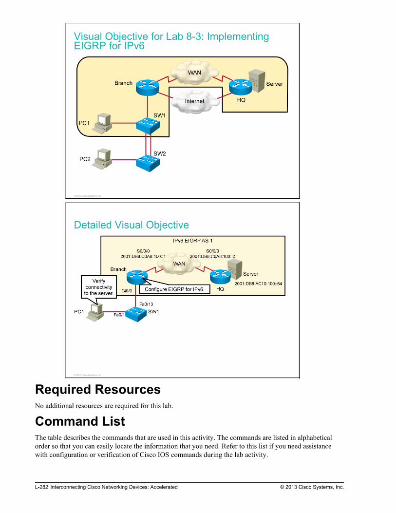
Visual Objective for Lab 8-3: ImplementingEIGRP for IPv6
© 2013 Cisco Systems, Inc.
Detailed Visual Objective
© 2013 Cisco Systems, Inc.
Required ResourcesNo additional resources are required for this lab.
Command ListThe table describes the commands that are used in this activity. The commands are listed in alphabeticalorder so that you can easily locate the information that you need. Refer to this list if you need assistancewith configuration or verification of Cisco IOS commands during the lab activity.
L-282 Interconnecting Cisco Networking Devices: Accelerated © 2013 Cisco Systems, Inc.

CommandsCommand Description
configure terminal Enters configuration mode.
interface interface Enters interface configuration mode.
ipv6 address ipv6_address/mask Sets an IPv6 address for an interface and the subnet mask.
ipv6 eigrp as_number Configures EIGRP for IPv6 on an interface.
ipv6 router eigrp as_number Creates and enters the IPv6 EIGRP router submode.
ipv6 unicast-routing Enables IPv6 unicast routing.
no shutdown Starts EIGRP for IPv6. The process is started by default on IOSversion 15.
ping destination_address Pings the specified address (IPv4 or IPv6).
show ipv6 eigrp interfaces Displays IPv6 EIGRP interfaces.
show ipv6 eigrp neighbors Displays IPv6 EIGRP neighbors.
show ipv6 eigrp topology Displays the IPv6 EIGRP topology table.
show ipv6 interface Displays the interface IPv6 setup.
show ipv6 route Displays the IP routing table.
Job AidsThese job aids are available to help you complete the lab activity.
The table shows the hardware that is used in the lab and the operating system that is running on the devices.
Device Hardware Operating System
Branch Cisco 2901 Integrated Services Router c2900-universalk9-mz.SPA.152-4.M4
HQ Cisco 2901 Integrated Services Router c2900-universalk9-mz.SPA.152-4.M4
SW1 Catalyst 2960 Series Switch c2960-lanbasek9-mz.150-1.SE3
SW2 Catalyst 2960 Series Switch c2960-lanlitek9-mz.150-1.SE3
PC1 Any PC Microsoft Windows 7
PC2 Any PC Microsoft Windows 7
The table shows the usernames and passwords that are used to access the equipment in this lab.
Device Username Password
PC1 Administrator admin
PC2 Administrator admin
© 2013 Cisco Systems, Inc. Lab Guide L-283

Topology and IP Addressing
Devices are connected with Ethernet and serial connections. The figure illustrates the interfaceidentification and IP addresses that are used in this lab setup.
Topology and IP Addressing
© 2013 Cisco Systems, Inc.
The table shows the interface identification and IP addresses that are used in this lab setup.
Device Interface IP Address/Subnet Mask
Branch GigabitEthernet0/0.1 (VLAN 1) 2001:db8 :0A01:100::1/64
Branch GigabitEthernet0/0.10 (VLAN 10) 2001:db8 :0A01:A00::1/64
Branch GigabitEthernet0/0.20 (VLAN 20) 2001:db8 :0A01:1400::1/64
Branch GigabitEthernet0/1 2001:db8 :D1A5:C900::1/64
Branch Serial0/0/0 2001:db8 :C0A8:100::1/64
HQ GigabitEthernet0/1 2001:db8 :D1A5:C900::2/64
HQ Serial0/0/0 2001:db8 :C0A8:100::2/64
HQ Loopback0 2001:db8 :AC10:100::64/64
PC1 Ethernet adapter local area connection IP address is acquired dynamically.
PC2 Ethernet adapter local area connection IP address is acquired dynamically.
Trunk and VLAN Setup
Three VLANs are configured on the switches. VLAN 1 is used for switch management, VLAN 10 is usedto connect PC1, and VLAN 20 is used to connect PC2. The two links between SW1 and SW2 are bondedinto an EtherChannel and a trunk is configured on it. The SW1 switch and the Branch router are connectedby a trunk link. The figure illustrates trunk and VLAN setup.
L-284 Interconnecting Cisco Networking Devices: Accelerated © 2013 Cisco Systems, Inc.

Trunk and VLAN Setup
© 2013 Cisco Systems, Inc.
IP Routing
As shown in the figure at the beginning of this lab, your pod has an HQ router configured with EIGRP forIPv6.
IP Routing
© 2013 Cisco Systems, Inc.
Task 1: Enable IPv6 on the InterfacesIn this task, you will enable IPv6 routing and configure an IPv6 address on the interface.
IPv6 is already properly configured on the HQ router, so you will only configure the Branch side.
© 2013 Cisco Systems, Inc. Lab Guide L-285

Activity ProcedureComplete the following steps:
Step 1
On the Branch router, enable routing for IPv6.
Step 2
On the Branch router, configure the IPv6 address on the serial interface connected to the HQ router. Alsoconfigure IPv6 addresses on subinterfaces GigabitEthernet0/0.1, GigabitEthernet0/0.10, andGigabitEthernet0/0.20.
Use the IPv6 address as shown in the visual objective of this exercise. The subnet mask should be /64.
Activity VerificationYou have completed this task when you attain these results:
Step 1
On the Branch router, verify that IPv6 is enabled. Verify that the global IPv6 unicast address is correctlyconfigured on Serial0/0/0, GigabitEthernet0/0.1, GigabitEthernet0/0.10a, and GigabitEthernet0/0.20.
Branch#show ipv6 interfaceGigabitEthernet0/0.1 is up, line protocol is up IPv6 is enabled, link-local address is FE80::FE99:47FF:FEE5:2700 No Virtual link-local address(es): Global unicast address(es): 2001:DB8:A01:100::1, subnet is 2001:DB8:A01:100::/64<output omitted>GigabitEthernet0/0.10 is up, line protocol is up IPv6 is enabled, link-local address is FE80::FE99:47FF:FEE5:2700 No Virtual link-local address(es): Global unicast address(es): 2001:DB8:A01:A00::1, subnet is 2001:DB8:A01:A00::/64<output omitted>GigabitEthernet0/0.20 is up, line protocol is up IPv6 is enabled, link-local address is FE80::FE99:47FF:FEE5:2700 No Virtual link-local address(es): Global unicast address(es): 2001:DB8:A01:1400::1, subnet is 2001:DB8:A01:1400::/64<output omitted>Serial0/0/0 is up, line protocol is up IPv6 is enabled, link-local address is FE80::FE99:47FF:FEE5:2700 No Virtual link-local address(es): Description: Link to HQ Global unicast address(es): 2001:DB8:C0A8:100::1, subnet is 2001:DB8:C0A8:100::/64<output omitted>
Task 2: Enable IPv6 EIGRPIn this task, you will enable EIGRP for IPv6.
The HQ router is already properly configured with EIGRP for IPv6.
L-286 Interconnecting Cisco Networking Devices: Accelerated © 2013 Cisco Systems, Inc.

Activity ProcedureComplete the following steps:
Step 1
On the Branch router, enable EIGRP routing for IPv6. Use AS 1.
Step 2
On the Branch router, configure IPv6 EIGRP routing on Serial0/0/0, GigabitEthernet0/0.1,GigabitEthernet0/0.10, and GigabitEthernet0/0.20.
Activity VerificationYou have completed this task when you attain these results:
Step 1
On the Branch router, verify the interfaces on which IPv6 EIGRP is enabled:
Branch#show ipv6 eigrp interfacesEIGRP-IPv6 Interfaces for AS(1) Xmit Queue PeerQ Mean Pacing Time Multicast PendingInterface Peers Un/Reliable Un/Reliable SRTT Un/Reliable Flow Timer RoutesSe0/0/0 1 0/0 0/0 686 0/16 3400 0Gi0/0.1 0 0/0 0/0 0 0/0 0 0Gi0/0.10 0 0/0 0/0 0 0/0 0 0Gi0/0.20 0 0/0 0/0 0 0/0 0 0
IPv6 EIGRP is enabled on first serial interface.
Step 2
On the Branch router, verify which IPv6 EIGRP neighbors are seen by the router:
Branch#show ipv6 eigrp neighbors IPv6-EIGRP neighbors for process 1H Address Interface Hold Uptime SRTT RTO Q Seq (sec) (ms) Cnt Num0 Link-local address: Se0/0/0 12 00:27:05 61 366 0 2 FE80::21E:7AFF:FEA3:5F30
The IPv6 EIGRP neighbor is specified with a link-local address.
© 2013 Cisco Systems, Inc. Lab Guide L-287

Step 3
On the Branch router, verify which routes are in the IPv6 EIGRP topology:
Branch#show ipv6 eigrp topologyEIGRP-IPv6 Topology Table for AS(1)/ID(209.165.201.1)Codes: P - Passive, A - Active, U - Update, Q - Query, R - Reply, r - reply Status, s - sia StatusP 2001:DB8:A01:100::/64, 1 successors, FD is 28160 via Connected, GigabitEthernet0/0.1P 2001:DB8:A01:1400::/64, 1 successors, FD is 28160 via Connected, GigabitEthernet0/0.20P 2001:DB8:C0A8:100::/64, 1 successors, FD is 2169856 via Connected, Serial0/0/0P 2001:DB8:A01:A00::/64, 1 successors, FD is 28160 via Connected, GigabitEthernet0/0.10P 2001:DB8:AC10:100::/64, 1 successors, FD is 2297856 via FE80::FE99:47FF:FEE5:2670 (2297856/128256), Serial0/0/0
The topology table holds successor routes to different destination networks. In this network, there are nofeasible successor routes.
Step 4
On the Branch router, verify which IPv6 routes are learned via IPv6 EIGRP:
Branch#show ipv6 route eigrp IPv6 Routing Table - 4 entriesCodes: C - Connected, L - Local, S - Static, R - RIP, B - BGP U - Per-user Static route, M - MIPv6 I1 - ISIS L1, I2 - ISIS L2, IA - ISIS interarea, IS - ISIS summary O - OSPF intra, OI - OSPF inter, OE1 - OSPF ext 1, OE2 - OSPF ext 2 ON1 - OSPF NSSA ext 1, ON2 - OSPF NSSA ext 2 D - EIGRP, EX - EIGRP externalD 2001:DB8:AC10:100::/64 [90/2297856] via FE80::21E:7AFF:FEA3:5F30, Serial0/0/0
There is one EIGRP route present in the IPv6 routing table.
L-288 Interconnecting Cisco Networking Devices: Accelerated © 2013 Cisco Systems, Inc.

Step 5
Go to PC1 and verify it has a global unicast IPv6 address configured using the ipconfig command.
Stateless address configuration is a unique feature to IPv6, where the client picks their own address basedon the prefix being advertised on their connected interface. All Cisco devices have the ability to participatein stateless address autoconfiguration.
Step 6
On PC1, issue a ping to the server at 2001:db8:ac10:100::64. This end-to-end connectivity test should besuccessful.
© 2013 Cisco Systems, Inc. Lab Guide L-289

L-290 Interconnecting Cisco Networking Devices: Accelerated © 2013 Cisco Systems, Inc.

Lab 9-1: Implementing OSPF
Activity OverviewObjectivesAfter completing this activity, you will be able to meet this objective:
Configure OSPF
Visual ObjectiveThe figure illustrates what you will accomplish in this activity.
Visual Objective for Lab 9-1: ImplementingOSPF
© 2013 Cisco Systems, Inc.

Detailed Visual ObjectiveOSPF Area 0
WAN
ServerQHhcnarB
S0/0/0
192.168.1.2
S0/0/0
192.168.1.1
172.16.1.100
PC1 SW1Fa0/1
Gi0/0
Fa0/13
10.1.10.100
Configure OSPF
© 2013 Cisco Systems, Inc.
Required ResourcesNo additional resources are required for this lab.
Command ListThe table describes the commands that are used in this activity. The commands are listed in alphabeticalorder so that you can easily locate the information that you need. Refer to this list if you need configurationcommand assistance during the lab activity.
Cisco CommandsCommand Description
interface interface Enters interface configuration mode.
ip address ip_address network_mask Sets an IP address, along with the subnet mask, on an interface. Enterinterface configuration mode to issue this command.
[no] router eigrp autonomous-system Disables or enables the EIGRP routing process.
router ospf process_id Starts the OSPF routing process with the specified process ID. Theprocess ID is of local significance, so two routers can have differentprocess IDs and still become neighbors.
show ip interfaces brief Shows a brief version of the operational state and IP information of allinterfaces.
show ip ospf interface Displays interface information related to OSPF.
show ip ospf neighbor Shows all OSPF neighbors of the router.
show ip route Displays the IP route table.
L-292 Interconnecting Cisco Networking Devices: Accelerated © 2013 Cisco Systems, Inc.

Microsoft Windows CommandsCommand Description
ping ip_address Issues a ping to the specified IP address.
Job AidsThese job aids are available to help you complete the lab activity.
The table shows the hardware that is used in the lab and the operating system that is running on the devices.
Device Hardware Operating System
Branch Cisco 2901 Integrated Services Router c2900-universalk9-mz.SPA.152-4.M1
HQ Cisco 2901 Integrated Services Router c2900-universalk9-mz.SPA.152-4.M1
SW1 Catalyst 2960 Series Switch c2960-lanbasek9-mz.150-1.SE3
SW2 Catalyst 2960 Series Switch c2960-lanlitek9-mz.150-1.SE3
PC1 Any PC Microsoft Windows 7
PC2 Any PC Microsoft Windows 7
The table shows the usernames and passwords that are used to access the equipment in this lab.
Device Username Password
PC1 Administrator admin
PC2 Administrator admin
Topology and IP Addressing
Devices are connected with Ethernet and serial connections. The figure illustrates the interfaceidentification and IP addresses that are used in this lab setup.
© 2013 Cisco Systems, Inc. Lab Guide L-293

Topology and IP Addressing
Internet
WAN
Server
PC1
PC2
SW1
SW2
Branch
HQ
Fa0/1
Fa0/1
Gi0/0
Fa0/13
Fa0/3 Fa0/4
Fa0/3 Fa0/4
Gi0/1
209.165.201.1
Gi0/1
209.165.201.2
S0/0/0
192.168.1.2
Tu0 (GRE)
192.168.2.1
S0/0/0
192.168.1.1
Tu0 (GRE)
192.168.2.1
10.1.10.100
10.1.20.100
10.1.1.11
10.1.1.12
VLAN 1—10.1.1.1
VLAN 10—10.1.10.1
VLAN 20—10.1.20.1
172.16.1.100
a0/3 Fa0
/3 Fa0
WWAWW N
© 2013 Cisco Systems, Inc.
The table shows the interface identification and IP addresses that are used in this lab setup.
Device Interface IP Address/Subnet Mask
Branch GigabitEthernet0/0.1 (VLAN 1) 10.1.1.1/24
Branch GigabitEthernet0/0.10 (VLAN 10) 10.1.10.1/24
Branch GigabitEthernet0/0.20 (VLAN 20) 10.1.20.1/24
Branch GigabitEthernet0/1 209.165.201.1/27
Branch Serial0/0/0 192.168.1.1/24
Branch Loopback10 10.100.100.100/32
Branch Tunnel0 192.168.2.1/24
HQ GigabitEthernet0/1 209.165.201.2/27
HQ Serial0/0/0 192.168.1.2/24
HQ Loopback0 172.16.1.100/24
HQ Tunnel0 192.168.2.2/24
SW1 VLAN 1 10.1.1.11/24
SW2 VLAN 1 10.1.1.12/24
PC1 Ethernet adapter local area connection 10.1.10.100/24
PC2 Ethernet adapter local area connection 10.1.20.100/24
L-294 Interconnecting Cisco Networking Devices: Accelerated © 2013 Cisco Systems, Inc.

Trunk and VLAN Setup
Three VLANs are configured on the switches. VLAN 1 is used for switch management, VLAN 10 is usedto connect PC1, and VLAN 20 is used to connect PC2. The two links between SW1 and SW2 are bondedinto an EtherChannel and a trunk is configured on it. The SW1 switch and the Branch router are connectedby a trunk link. The figure illustrates trunk and VLAN setup.
Trunk and VLAN Setup
© 2013 Cisco Systems, Inc.
IP Routing
EIGRP is running in AS 1 between the HQ and Branch routers. The figure illustrates the EIGRP setup.
IP Routing
© 2013 Cisco Systems, Inc.
© 2013 Cisco Systems, Inc. Lab Guide L-295

Task 1: Configure OSPFIn this task, you will first remove EIGRP (with the AS of 1) and then configure OSPF on the Branch router.The HQ router was configured with OSPF by your coworker. The two routers will then become neighborsand exchange routing information.
Activity ProcedureComplete the following steps:
Step 1
Access the Branch router.
Step 2
Remove the EIGRP routing process from the Branch router. Recall that EIGRP has lower administrativedistance then OSPF. Without removing EIGRP, OSPF routes would not be considered when installingroutes into the routing table.
Step 3
Configure the Loopback10 interface on the Branch router. Assign the 10.100.100.100/32 IP address to theinterface. This IP address will serve as the router ID for OSPF.
Step 4
Create the OSPF routing process on the Branch router. Use 1 as the process ID number.
Step 5
Enable OSPF for Area 0 on the WAN interface (Serial0/0/0).
Step 6
Configure OSPF so that it also advertises networks 10.1.1.0/24, 10.1.10.0/24, and 10.1.20.0./24.
The HQ router was already configured with OSPF by your colleague.
Activity VerificationYou have completed this task when you attain these results:
L-296 Interconnecting Cisco Networking Devices: Accelerated © 2013 Cisco Systems, Inc.

Step 1
Verify OSPF process status:
Branch#show ip protocols*** IP Routing is NSF aware ***Routing Protocol is "ospf 1" Outgoing update filter list for all interfaces is not set Incoming update filter list for all interfaces is not set Router ID 10.100.100.100 Number of areas in this router is 1. 1 normal 0 stub 0 nssa Maximum path: 4 Routing for Networks: 10.1.1.0 0.0.0.255 area 0 10.1.10.0 0.0.0.255 area 0 10.1.20.0 0.0.0.255 area 0 192.168.1.0 0.0.0.255 area 0 Routing Information Sources: Gateway Distance Last Update 1.1.1.1 110 00:01:11 Distance: (default is 110)
You should see the OSPF router ID set to the IP address of the Loopback10 interface. You should also seethat OSPF is enabled on the WAN and LAN interfaces for Area 0.
Step 2
On the Branch router, determine whether you see the HQ router as a neighbor.
The HQ router is configured with the router ID of 1.1.1.1.
Branch#show ip ospf neighborNeighbor ID Pri State Dead Time Address Interface1.1.1.1 0 FULL/ - 00:00:35 192.168.1.2 Serial0/0/0
Step 3
On the Branch router, verify that GigabitEthernet0/0.1, GigabitEthernet0/0.10, GigabitEthernet0/0.20, andGigabitEthernet0/1 are enabled for the OSPF process.
Branch#show ip ospf interface briefInterface PID Area IP Address/Mask Cost State Nbrs F/CGi0/0.20 1 0 10.1.20.1/24 1 DR 0/0Gi0/0.10 1 0 10.1.10.1/24 1 DR 0/0Gi0/0.1 1 0 10.1.1.1/24 1 DR 0/0Se0/0/0 1 0 192.168.1.1/24 64 P2P 1/1
© 2013 Cisco Systems, Inc. Lab Guide L-297

Step 4
On the Branch router, view the routing table. Note the entry for the 172.16.1.0/24 network that wasacquired via the OSPF routing process.
Branch#show ip routeCodes: L - local, C - connected, S - static, R - RIP, M - mobile, B - BGP D - EIGRP, EX - EIGRP external, O - OSPF, IA - OSPF inter area N1 - OSPF NSSA external type 1, N2 - OSPF NSSA external type 2 E1 - OSPF external type 1, E2 - OSPF external type 2 i - IS-IS, su - IS-IS summary, L1 - IS-IS level-1, L2 - IS-IS level-2 ia - IS-IS inter area, * - candidate default, U - per-user static route o - ODR, P - periodic downloaded static route, H - NHRP, l - LISP + - replicated route, % - next hop overrideGateway of last resort is 209.165.201.2 to network 0.0.0.0S* 0.0.0.0/0 [1/0] via 209.165.201.2 10.0.0.0/8 is variably subnetted, 7 subnets, 2 masksC 10.1.1.0/24 is directly connected, GigabitEthernet0/0.1L 10.1.1.1/32 is directly connected, GigabitEthernet0/0.1C 10.1.10.0/24 is directly connected, GigabitEthernet0/0.10L 10.1.10.1/32 is directly connected, GigabitEthernet0/0.10C 10.1.20.0/24 is directly connected, GigabitEthernet0/0.20L 10.1.20.1/32 is directly connected, GigabitEthernet0/0.20C 10.100.100.100/32 is directly connected, Loopback10 172.16.0.0/24 is subnetted, 1 subnetsO 172.16.1.0 [110/65] via 192.168.1.2, 00:00:36, Serial0/0/0 192.168.1.0/24 is variably subnetted, 2 subnets, 2 masksC 192.168.1.0/24 is directly connected, Serial0/0/0L 192.168.1.1/32 is directly connected, Serial0/0/0 192.168.2.0/24 is variably subnetted, 2 subnets, 2 masksC 192.168.2.0/24 is directly connected, Tunnel0L 192.168.2.1/32 is directly connected, Tunnel0 209.165.201.0/24 is variably subnetted, 2 subnets, 2 masksC 209.165.201.0/27 is directly connected, GigabitEthernet0/1L 209.165.201.1/32 is directly connected, GigabitEthernet0/1
Step 5
From PC1, ping the 172.16.1.100 server. Your attempt should be successful, because now the HQ routerknows how to get back to the 10.1.10.0/24 network.
C:\Users\Administrator>ping 172.16.1.100 Pinging 172.16.1.100 with 32 bytes of data:Reply from 172.16.1.100: bytes=32 time=44ms TTL=128Reply from 172.16.1.100: bytes=32 time=41ms TTL=128Reply from 172.16.1.100: bytes=32 time=36ms TTL=128Reply from 172.16.1.100: bytes=32 time=36ms TTL=128Ping statistics for 172.16.1.100: Packets: Sent = 4, Received = 4, Lost = 0 (0% loss), Approximate round trip times in milli-seconds: Minimum = 36ms, Maximum = 44ms, Average = 39ms
L-298 Interconnecting Cisco Networking Devices: Accelerated © 2013 Cisco Systems, Inc.

Lab 9-2: ConfiguringMultiarea OSPF
Activity OverviewObjectivesAfter completing this activity, you will be able to meet these objectives:
Configure multiarea OSPF
Verify multiarea OSPF configuration
Visual ObjectiveThe figure illustrates what you will accomplish in this activity.

Visual Objective for Lab 9-2: ConfiguringMultiarea OSPF
© 2013 Cisco Systems, Inc.
Detailed Visual Objective
OSPF Area 1
OSPF Area 0
WAN
ServerBranch
HQ
S0/0/0
192.168.1.2
S0/0/0
192.168.1.1 172.16.1.100
Configure
multiarea OSPF
PC1 SW1Fa0/1
Gi0/0
Fa0/13
10.1.10.100Verify connectivity
to 172.16.1.100
© 2013 Cisco Systems, Inc.
Required ResourcesNo additional resources are required for this lab.
Command ListThe table describes the commands that are used in this activity. The commands are listed in alphabeticalorder so that you can easily locate the information that you need. Refer to this list if you need configurationcommand assistance during the lab activity.
L-300 Interconnecting Cisco Networking Devices: Accelerated © 2013 Cisco Systems, Inc.

CommandsCommand Description
configure terminal Enters global configuration mode.
ip address ip_address mask Configures the IP address on an interface.
interface interface Enters interface configuration mode.
network network wildcard_mask areaarea_id
Enables the OSPF routing protocol for the specified area on theinterfaces that match the specified network.
[no] router eigrp autonomous-system Disables or enables the EIGRP routing process.
router ospf process_id Enables the OSPF routing process.
show ip ospf interfaces brief Shows interfaces that are enabled for the OSPF routing process.
show ip ospf neighbors Shows OSPF neighbors.
show ip protocols Displays the routing protocol status and routing protocol timerinformation that is associated with the router.
show ip route [ospf] Displays the routing table.
telnet ip_address Uses Telnet to connect to the specified host.
Job AidsThese job aids are available to help you complete the lab activity.
The table shows the hardware that is used in the lab and the operating system that is running on the devices.
Device Hardware Operating System
Branch Cisco 2901 Integrated Services Router c2900-universalk9-mz.SPA.152-4.M4
HQ Cisco 2901 Integrated Services Router c2900-universalk9-mz.SPA.152-4.M4
SW1 Catalyst 2960 Series Switch c2960-lanbasek9-mz.150-1.SE3
SW2 Catalyst 2960 Series Switch c2960-lanlitek9-mz.150-1.SE3
PC1 Any PC Microsoft Windows 7
PC2 Any PC Microsoft Windows 7
The table shows the usernames and passwords that are used to access the equipment in this lab.
Device Username Password
PC1 Administrator admin
PC2 Administrator admin
Topology and IP Addressing
Devices are connected with Ethernet and serial connections. The figure illustrates the interfaceidentification and IP addresses that are used in this lab setup.
© 2013 Cisco Systems, Inc. Lab Guide L-301

Topology and IP Addressing
Internet
WAN
Server
PC1
PC2
SW1
SW2
Branch
HQ
Fa0/1
Fa0/1
Gi0/0
Fa0/13
Fa0/3 Fa0/4
Fa0/3 Fa0/4
Gi0/1
209.165.201.1
Gi0/1
209.165.201.2
S0/0/0
192.168.1.2
Tu0 (GRE)
192.168.2.1
S0/0/0
192.168.1.1
Tu0 (GRE)
192.168.2.1
10.1.10.100
10.1.20.100
10.1.1.11
10.1.1.12
VLAN 1—10.1.1.1
VLAN 10—10.1.10.1
VLAN 20—10.1.20.1
172.16.1.100
a0/3 Fa0
/3 Fa0
WWAWW N
© 2013 Cisco Systems, Inc.
The table shows the interface identification and IP addresses that are used in this lab setup.
Device Interface IP Address/Subnet Mask
Branch GigabitEthernet0/0.1 (VLAN 1) 10.1.1.1/24
Branch GigabitEthernet0/0.10 (VLAN 10) 10.1.10.1/24
Branch GigabitEthernet0/0.20 (VLAN 20) 10.1.20.1/24
Branch GigabitEthernet0/1 209.165.201.1/27
Branch Serial0/0/0 192.168.1.1/24
Branch Loopback10 10.100.100.100/32
Branch Tunnel0 192.168.2.1/24
HQ GigabitEthernet0/1 209.165.201.2/27
HQ Serial0/0/0 192.168.1.2/24
HQ Loopback0 172.16.1.100/24
HQ Tunnel0 192.168.2.2/24
SW1 VLAN 1 10.1.1.11/24
SW2 VLAN 1 10.1.1.12/24
PC1 Ethernet adapter local area connection 10.1.10.100/24
PC2 Ethernet adapter local area connection 10.1.20.100/24
L-302 Interconnecting Cisco Networking Devices: Accelerated © 2013 Cisco Systems, Inc.

Trunk and VLAN Setup
Three VLANs are configured on the switches. VLAN 1 is used for switch management, VLAN 10 is usedto connect PC1, and VLAN 20 is used to connect PC2. The two links between SW1 and SW2 are bondedinto an EtherChannel and a trunk is configured on it. The SW1 switch and the Branch router are connectedby a trunk link. The figure illustrates trunk and VLAN setup.
Trunk and VLAN Setup
© 2013 Cisco Systems, Inc.
IP Routing
As the figure shows, OSPF is set up as the routing protocol on both routers.
Task 1: Configure Multiarea OSPFIn this task, you will configure multiarea OSPF on the Branch router. You will set the LAN interfaces forOSPF Area 1 and the WAN interface for OSPF Area 0. The HQ router has been preconfigured.
Activity ProcedureComplete the following steps:
Step 1
Access the Branch router.
© 2013 Cisco Systems, Inc. Lab Guide L-303

Step 2
Reconfigure the LAN interfaces (GigabitEthernet0/0 subinterfaces) and the Loopback10 interface to be partof OSPF Area 1.
Activity VerificationYou have completed this task when you attain this result:
Step 1
Verify the OSPF process status:
Branch#show ip protocols*** IP Routing is NSF aware ***Routing Protocol is "ospf 1" Outgoing update filter list for all interfaces is not set Incoming update filter list for all interfaces is not set Router ID 10.100.100.100 It is an area border router Number of areas in this router is 2. 2 normal 0 stub 0 nssa Maximum path: 4 Routing for Networks: 10.1.1.0 0.0.0.255 area 1 10.1.10.0 0.0.0.255 area 1 10.1.20.0 0.0.0.255 area 1 10.100.100.100 0.0.0.0 area 1 192.168.1.0 0.0.0.255 area 0 Routing Information Sources: Gateway Distance Last Update 1.1.1.1 110 00:00:50 Distance: (default is 110)
You should see the OSPF router ID set to the IP address of the Loopback10 interface. You should also seethat OSPF is enabled on the WAN interface for Area 0 and on the LAN and loopback interfaces for Area 1.
Task 2: Verify Multiarea OSPFIn this task, you will verify multiarea OSPF configuration and operations.
Activity ProcedureComplete the following steps:
L-304 Interconnecting Cisco Networking Devices: Accelerated © 2013 Cisco Systems, Inc.

Step 1
On the Branch router, verify OSPF adjacencies:
Branch#show ip ospf neighborNeighbor ID Pri State Dead Time Address Interface1.1.1.1 0 FULL/ - 00:00:33 192.168.1.2 Serial0/0/0
You should see the HQ router as a neighbor. The HQ router ID is 1.1.1.1. The neighbors should be in thefull state.
Step 2
On the Branch router, investigate which interfaces are enabled for OSPF.
Branch#show ip ospf interface briefInterface PID Area IP Address/Mask Cost State Nbrs F/CSe0/0/0 1 0 192.168.1.1/24 64 P2P 1/1Lo10 1 1 10.100.100.100/32 1 LOOP 0/0Gi0/0.20 1 1 10.1.20.1/24 1 DR 0/0Gi0/0.10 1 1 10.1.10.1/24 1 DR 0/0Gi0/0.1 1 1 10.1.1.1/24 1 DR 0/0
Step 3
On the Branch router, verify OSPF routes in the routing table:
Branch#show ip route ospf Codes: L - local, C - connected, S - static, R - RIP, M - mobile, B - BGP D - EIGRP, EX - EIGRP external, O - OSPF, IA - OSPF inter area N1 - OSPF NSSA external type 1, N2 - OSPF NSSA external type 2 E1 - OSPF external type 1, E2 - OSPF external type 2 i - IS-IS, su - IS-IS summary, L1 - IS-IS level-1, L2 - IS-IS level-2 ia - IS-IS inter area, * - candidate default, U - per-user static route o - ODR, P - periodic downloaded static route, H - NHRP, l - LISP + - replicated route, % - next hop overrideGateway of last resort is not set 172.16.0.0/24 is subnetted, 1 subnetsO 172.16.1.0 [110/65] via 192.168.1.2, 00:00:04, Serial0/0/0
You should see the 172.16.1.0/24 network in the routing table. Is the network seen as an interarea or intra-area route? Why?
© 2013 Cisco Systems, Inc. Lab Guide L-305

Step 4
From the Branch router, use Telnet to connect to the HQ router:
Branch#telnet 192.168.1.2Trying 192.168.1.2 ... OpenHQ#
Step 5
On the HQ router, verify OSPF routes in the routing table:
HQ#show ip route ospf Codes: L - local, C - connected, S - static, R - RIP, M - mobile, B - BGP D - EIGRP, EX - EIGRP external, O - OSPF, IA - OSPF inter area N1 - OSPF NSSA external type 1, N2 - OSPF NSSA external type 2 E1 - OSPF external type 1, E2 - OSPF external type 2 i - IS-IS, su - IS-IS summary, L1 - IS-IS level-1, L2 - IS-IS level-2 ia - IS-IS inter area, * - candidate default, U - per-user static route o - ODR, P - periodic downloaded static route, H - NHRP, l - LISP + - replicated route, % - next hop overrideGateway of last resort is not set 10.0.0.0/8 is variably subnetted, 4 subnets, 2 masksO IA 10.1.1.0/24 [110/65] via 192.168.1.1, 00:06:41, Serial0/0/0O IA 10.1.10.0/24 [110/65] via 192.168.1.1, 00:07:36, Serial0/0/0O IA 10.1.20.0/24 [110/65] via 192.168.1.1, 00:07:36, Serial0/0/0O IA 10.100.100.100/32 [110/65] via 192.168.1.1, 00:20:57, Serial0/0/0
You should see the LAN networks in the routing table. Are the LAN networks seen as an interarea or intra-area route? Why?
Step 6
Access PC1.
Step 7
Open a command prompt on PC1. Ping the server at 172.16.1.100. The ping should be successful.
C:\Windows\system32>ping 172.16.1.100Pinging 172.16.1.100 with 32 bytes of data:Reply from 172.16.1.100: bytes=32 time=37ms TTL=254Reply from 172.16.1.100: bytes=32 time=36ms TTL=254Reply from 172.16.1.100: bytes=32 time=36ms TTL=254Reply from 172.16.1.100: bytes=32 time=36ms TTL=254Ping statistics for 172.16.1.100: Packets: Sent = 4, Received = 4, Lost = 0 (0% loss),Approximate round trip times in milli-seconds: Minimum = 36ms, Maximum = 37ms, Average = 36ms
L-306 Interconnecting Cisco Networking Devices: Accelerated © 2013 Cisco Systems, Inc.

Step 8
Save the changes that you made to the configuration on the Branch router.
Activity VerificationNo additional verification is needed in this task.
© 2013 Cisco Systems, Inc. Lab Guide L-307

L-308 Interconnecting Cisco Networking Devices: Accelerated © 2013 Cisco Systems, Inc.

Lab 9-3: TroubleshootingMultiarea OSPF
Activity OverviewObjectivesIn this lab, you will be presented with two multiarea OSPF troubleshooting tickets. After this lab activity,you will be able to meet these objectives:
Troubleshoot OSPF neighbor issues
Troubleshoot OSPF routing table issues
Visual ObjectiveThe figure illustrates what you will accomplish in this activity.
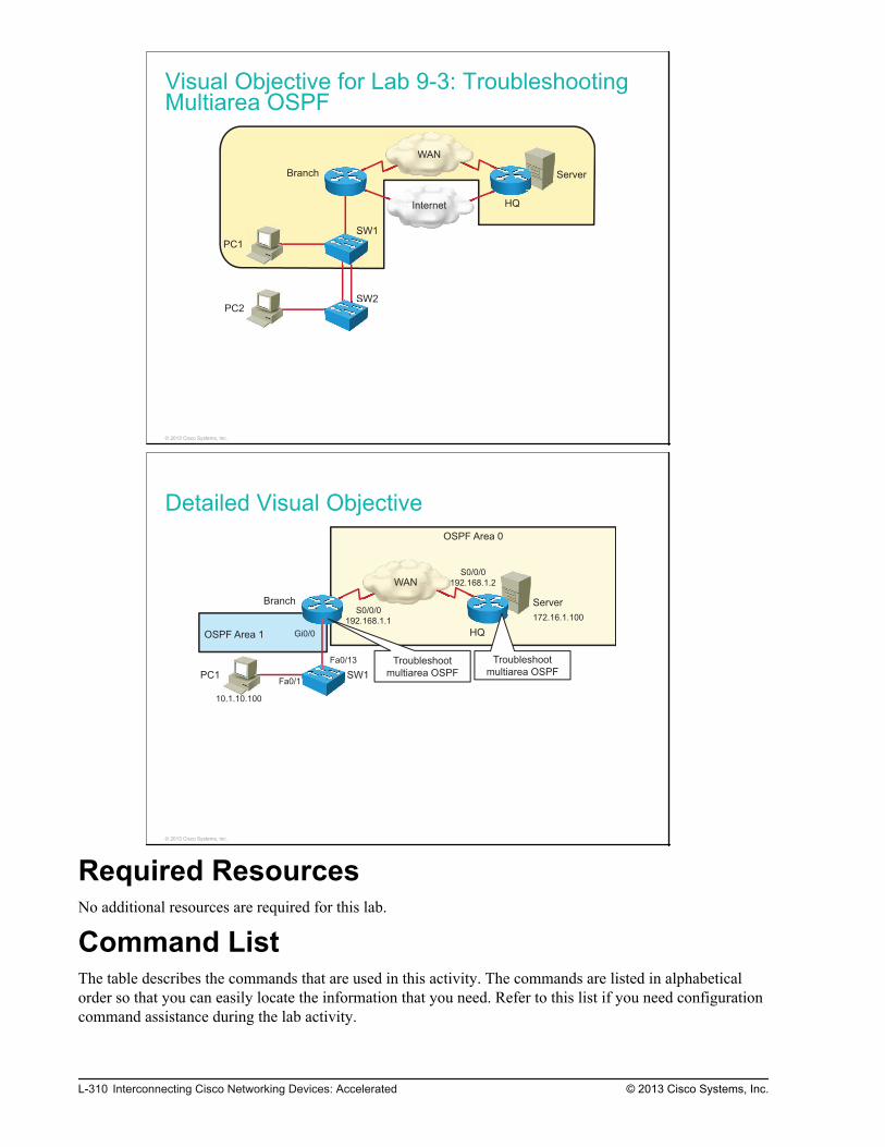
Visual Objective for Lab 9-3: TroubleshootingMultiarea OSPF
Internet
WAN
Server
PC1
PC2
SW1
SW2
Branch
HQ
SW
SW
© 2013 Cisco Systems, Inc.
Detailed Visual Objective
OSPF Area 1
OSPF Area 0
WAN
ServerBranch
HQ
S0/0/0
192.168.1.2
S0/0/0
192.168.1.1172.16.1.100
Troubleshoot
multiarea OSPFPC1 SW1Fa0/1
Gi0/0
Fa0/13
10.1.10.100
Troubleshoot
multiarea OSPF
© 2013 Cisco Systems, Inc.
Required ResourcesNo additional resources are required for this lab.
Command ListThe table describes the commands that are used in this activity. The commands are listed in alphabeticalorder so that you can easily locate the information that you need. Refer to this list if you need configurationcommand assistance during the lab activity.
L-310 Interconnecting Cisco Networking Devices: Accelerated © 2013 Cisco Systems, Inc.

CommandsCommand Description
configure terminal Enters global configuration mode.
debug ip ospf adj Enables debugging of OSPF adjacency events.
network network wildcard_mask areaarea_id
Enables the OSPF routing protocol for the specified area on theinterfaces that match the specified network.
[no] passive-interface interface Disables the interface as a passive interface.
ping ip_address source interface Pings an IP address from the specified interface.
router ospf process_id Enables the OSPF routing process.
show ip interface interface Displays the interface status and other IP-related information.
show ip ospf interfaces Shows OSPF-related information on interfaces.
show ip ospf neighbors Shows OSPF neighbors.
show ip protocols Displays routing protocol status and routing protocol timer informationthat are associated with the router.
show ip route Displays the routing table.
telnet ip_address Uses Telnet to connect to the specified host.
Job AidsThese job aids are available to help you complete the lab activity.
Pod Information
Each pod has two switches, two routers, and two PCs. The server is simulated on the Headquarters router bythe IP address that is assigned to the loopback interface.
The table shows the hardware that is used in the lab and the operating system that is running on the devices.
Device Hardware Operating System
Branch Cisco 2901 Integrated Services Router c2900-universalk9-mz.SPA.152-4.M4
Headquarters
Cisco 2901 Integrated Services Router c2900-universalk9-mz.SPA.152-4.M4
SW1 Catalyst 2960 Series Switch c2960-lanbasek9-mz.150-1.SE3
SW2 Catalyst 2960 Series Switch c2960-lanlitek9-mz.150-1.SE3
PC1 Any PC Microsoft Windows 7
PC2 Any PC Microsoft Windows 7
The table shows the usernames and passwords that are used to access the equipment in this lab.
Device Username Password
PC1 Administrator admin
PC2 Administrator admin
© 2013 Cisco Systems, Inc. Lab Guide L-311

Topology and IP Addressing
Devices are connected with Ethernet and serial connections. The figure illustrates the interfaceidentification and IP addresses that are used in this lab setup.
Topology and IP Addressing
Internet
WAN
Server
PC1
PC2
SW1
SW2
Branch
HQ
Fa0/1
Fa0/1
Gi0/0
Fa0/13
Fa0/3 Fa0/4
Fa0/3 Fa0/4
Gi0/1
209.165.201.1
Gi0/1
209.165.201.2
S0/0/0
192.168.1.2
Tu0 (GRE)
192.168.2.1
S0/0/0
192.168.1.1
Tu0 (GRE)
192.168.2.1
10.1.10.100
10.1.20.100
10.1.1.11
10.1.1.12
VLAN 1—10.1.1.1
VLAN 10—10.1.10.1
VLAN 20—10.1.20.1
172.16.1.100
a0/3 Fa0
/3 Fa0
WWAWW N
© 2013 Cisco Systems, Inc.
The table shows the interface identification and IP addresses that are used in this lab setup.
Device Interface IP Address/Subnet Mask
Branch GigabitEthernet0/0.1 (VLAN 1) 10.1.1.1/24
Branch GigabitEthernet0/0.10 (VLAN 10) 10.1.10.1/24
Branch GigabitEthernet0/0.20 (VLAN 20) 10.1.20.1/24
Branch GigabitEthernet0/1 209.165.201.1/27
Branch Serial0/0/0 192.168.1.1/24
Branch Loopback10 10.100.100.100/32
Branch Tunnel0 192.168.2.1/24
HQ GigabitEthernet0/1 209.165.201.2/27
HQ Serial0/0/0 192.168.1.2/24
HQ Loopback0 172.16.1.100/24
HQ Tunnel0 192.168.2.2/24
SW1 VLAN 1 10.1.1.11/24
SW2 VLAN 1 10.1.1.12/24
PC1 Ethernet adapter local area connection 10.1.10.100/24
PC2 Ethernet adapter local area connection 10.1.20.100/24
L-312 Interconnecting Cisco Networking Devices: Accelerated © 2013 Cisco Systems, Inc.

Trunk and VLAN Setup
Three VLANs are configured on the switches. VLAN 1 is used for switch management, VLAN 10 is usedto connect PC1, and VLAN 20 is used to connect PC2. The two links between SW1 and SW2 are bondedinto an EtherChannel, and a trunk is configured on it. The SW1 switch and the Branch router are connectedby a trunk link. The figure illustrates the trunk and VLAN setup.
Trunk and VLAN Setup
VLAN 1
VLAN 10
VLAN 20
PC1
PC2
SW1
SW2
Branch
Trunk
© 2013 Cisco Systems, Inc.
© 2013 Cisco Systems, Inc. Lab Guide L-313

IP Routing
The HQ router has interfaces Serial0/0/0 and Loopback0 in OSPF Area 0. The Branch router has only theinterface Serial0/0/0 enabled in Area 0. All of the interfaces on the Branch router toward the LAN areenabled for OSPF Area 1. The HQ router ID is 1.1.1.1.
IP RoutingOSPF Area 1 OSPF Area 0
Branch HQ10.1.1.0/24
10.1.10.0/24
10.1.20.0/24
10.100.100.100/32
172.16.1.0/24
192.168.1.0/24192.168.1.0/24
© 2013 Cisco Systems, Inc.
Task 1: Troubleshoot OSPF Neighbor IssuesYou have been informed that users behind the Branch router cannot communicate with the server in thecentral location. As a junior network engineer, you have to troubleshoot and correct the problem. A seniornetwork engineer has confirmed that the problem is in an OSPF adjacency between the Headquarters andBranch routers.
Activity ProcedureComplete the following steps:
Step 1
Access the Branch router.
L-314 Interconnecting Cisco Networking Devices: Accelerated © 2013 Cisco Systems, Inc.

Step 2
From the Branch router, ping the server at 172.16.1.100. Use GigabitEthernet0/0.10 as the source interface:
Branch# ping 172.16.1.100 source GigabitEthernet0/0.10Type escape sequence to abort.Sending 5, 100-byte ICMP Echos to 172.16.1.100, timeout is 2 seconds:Packet sent with a source address of 10.1.10.1 .....Success rate is 0 percent (0/5)
The ping should not be successful. This indicates a problem in connectivity between users behind theBranch router and the server in the central location.
Step 3
Examine the routing table on the Branch router. Verify if you received the 172.16.1.0/24 route from theHeadquarters router:
Branch# show ip route 172.16.1.0% Network not in table
You should see no route on the 172.16.1.0/24 network in the routing table.
Step 4
Verify OSPF neighbors:
Branch# show ip ospf neighborBranch#
You should see no OSPF neighbors on the Branch router.
Step 5
Verify if the interface connecting the Branch router to the Headquarters router is enabled on the Branchrouter. Use the visual objective to determine the interface:
Branch# show ip interface Serial0/0/0Serial0/0/0 is up, line protocol is up<output omitted>
Is the Serial0/0/0 interface enabled on the Branch router?
© 2013 Cisco Systems, Inc. Lab Guide L-315

Step 6
Verify if OSPF is enabled on the Serial 0/0/0 interface of the Branch router:
Branch# show ip protocols *** IP Routing is NSF aware ***Routing Protocol is "ospf 1" Outgoing update filter list for all interfaces is not set Incoming update filter list for all interfaces is not set Router ID 10.100.100.100 It is an area border router Number of areas in this router is 2. 2 normal 0 stub 0 nssa Maximum path: 4 Routing for Networks: 10.1.1.0 0.0.0.255 area 1 10.1.10.0 0.0.0.255 area 1 10.1.20.0 0.0.0.255 area 1 10.100.100.100 0.0.0.0 area 1 192.168.1.0 0.0.0.255 area 0<output omitted>
For which OSPF area is the interface enabled?
L-316 Interconnecting Cisco Networking Devices: Accelerated © 2013 Cisco Systems, Inc.

Step 7
Verify if the Serial0/0/0 interface is configured as a passive interface:
Branch# show ip protocols *** IP Routing is NSF aware ***Routing Protocol is "ospf 1" Outgoing update filter list for all interfaces is not set Incoming update filter list for all interfaces is not set Router ID 10.100.100.100 Number of areas in this router is 2. 2 normal 0 stub 0 nssa Maximum path: 4 Routing for Networks: 10.1.1.0 0.0.0.255 area 1 10.1.10.0 0.0.0.255 area 1 10.1.20.0 0.0.0.255 area 1 10.100.100.100 0.0.0.0 area 1 192.168.1.0 0.0.0.255 area 0 Passive Interface(s): Embedded-Service-Engine0/0 GigabitEthernet0/0 GigabitEthernet0/1 GigabitEthernet0/2 GigabitEthernet0/3 Loopback10 Serial0/0/0<output omitted>
Is the Serial0/0/0 interface configured as a passive interface? Why are adjacencies not established overpassive interfaces?
Step 8
Correct the problem by configuring the Serial0/0/0 interface as a nonpassive interface.
© 2013 Cisco Systems, Inc. Lab Guide L-317

Step 9
Verify if the Serial0/0/0 interface is configured as an OSPF nonpassive interface:
Branch# show ip protocols *** IP Routing is NSF aware ***Routing Protocol is "ospf 1" Outgoing update filter list for all interfaces is not set Incoming update filter list for all interfaces is not set Router ID 10.100.100.100 Number of areas in this router is 2. 2 normal 0 stub 0 nssa Maximum path: 4 Routing for Networks: 10.1.1.0 0.0.0.255 area 1 10.1.10.0 0.0.0.255 area 1 10.1.20.0 0.0.0.255 area 1 10.100.100.100 0.0.0.0 area 1 192.168.1.0 0.0.0.255 area 0 Passive Interface(s): Embedded-Service-Engine0/0 GigabitEthernet0/0 GigabitEthernet0/1 GigabitEthernet0/2 GigabitEthernet0/3 Loopback10<output omitted>
Serial0/0/0 should no longer be configured as a passive interface.
Step 10
Verify if the Branch router established OSPF adjacency with the Headquarters router after you corrected theproblem:
Branch# show ip ospf neighborBranch#
You should still see no OSPF neighbors on the Branch router. Proceed with troubleshooting the OSPFadjacency.
L-318 Interconnecting Cisco Networking Devices: Accelerated © 2013 Cisco Systems, Inc.

Step 11
Enable debugging of OSPF adjacencies using the debug ip ospf adj command and observe the output in theconsole:
Branch# debug ip ospf adjOSPF adjacency debugging is onBranch#Oct 30 09:02:28.471: OSPF-1 ADJ S0/0/0: Rcv pkt from 192.168.1.2, area 0.0.0.0, mismatched area 0.0.0.1 in the header
You should see routers trying to exchange hello packets, but the OSPF area is mismatched and thereforethey can not become neighbors. Because the Branch router is configured for a correct OSPF area, theHeadquarters router is probably configured for an incorrect OSPF area.
Step 12
Disable debugging of OSPF adjacencies using the no debug ip ospf adj command.
Branch# no debug ip ospf adjOSPF adjacency debugging is off
Step 13
Correct the problem by configuring the Serial0/0/0 interface for OSPF Area 0 on the Headquarters router.
Step 14
Exit the Telnet session. Verify if the Branch router established an OSPF adjacency with the Headquartersrouter after you corrected the problem.
HQ# exit[Connection to 192.168.1.2 closed by foreign host]Branch# show ip ospf neighborsNeighbor ID Pri State Dead Time Address Interface1.1.1.1 0 FULL/ - 00:00:32 192.168.1.2 Serial0/0/0
You should see that the OSPF adjacency was established this time. You successfully corrected the OSPFneighbor issues.
Activity VerificationNo additional verification is needed in this task.
© 2013 Cisco Systems, Inc. Lab Guide L-319
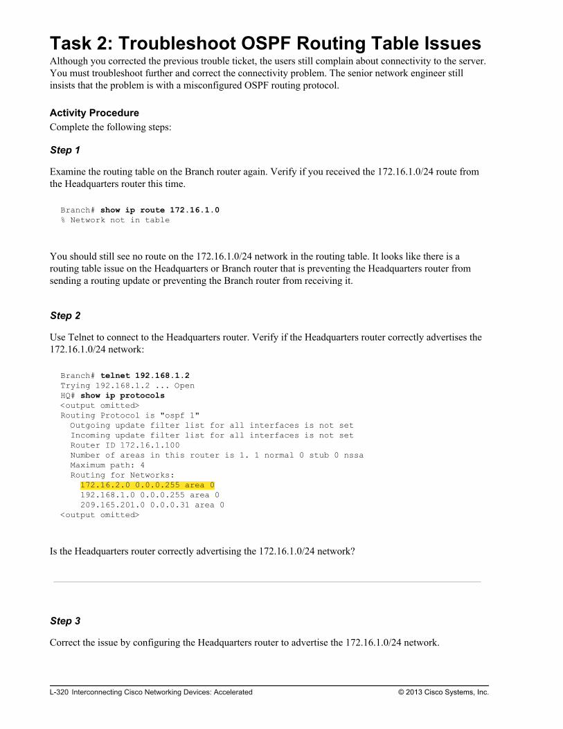
Task 2: Troubleshoot OSPF Routing Table IssuesAlthough you corrected the previous trouble ticket, the users still complain about connectivity to the server.You must troubleshoot further and correct the connectivity problem. The senior network engineer stillinsists that the problem is with a misconfigured OSPF routing protocol.
Activity ProcedureComplete the following steps:
Step 1
Examine the routing table on the Branch router again. Verify if you received the 172.16.1.0/24 route fromthe Headquarters router this time.
Branch# show ip route 172.16.1.0% Network not in table
You should still see no route on the 172.16.1.0/24 network in the routing table. It looks like there is arouting table issue on the Headquarters or Branch router that is preventing the Headquarters router fromsending a routing update or preventing the Branch router from receiving it.
Step 2
Use Telnet to connect to the Headquarters router. Verify if the Headquarters router correctly advertises the172.16.1.0/24 network:
Branch# telnet 192.168.1.2 Trying 192.168.1.2 ... OpenHQ# show ip protocols <output omitted> Routing Protocol is "ospf 1" Outgoing update filter list for all interfaces is not set Incoming update filter list for all interfaces is not set Router ID 172.16.1.100 Number of areas in this router is 1. 1 normal 0 stub 0 nssa Maximum path: 4 Routing for Networks: 172.16.2.0 0.0.0.255 area 0 192.168.1.0 0.0.0.255 area 0 209.165.201.0 0.0.0.31 area 0<output omitted>
Is the Headquarters router correctly advertising the 172.16.1.0/24 network?
Step 3
Correct the issue by configuring the Headquarters router to advertise the 172.16.1.0/24 network.
L-320 Interconnecting Cisco Networking Devices: Accelerated © 2013 Cisco Systems, Inc.

Step 4
Save the changes that you made on the Headquarters router.
Exit the Telnet session.
Save the changes that you made on the Branch router.
Activity VerificationYou have completed this task when you attain these results:
Step 1
On the Branch router, examine the routing table. Verify if you received the 172.16.1.0/24 route from theHeadquarters router this time.
Branch# show ip route 172.16.1.0Routing entry for 172.16.1.0/24 Known via "ospf 1", distance 110, metric 66, type intra area Last update from 192.168.1.2 on Serial0/0/0, 00:02:28 ago Routing Descriptor Blocks: * 192.168.1.2, from 172.16.1.100, 00:02:28 ago, via Serial0/0/0 Route metric is 66, traffic share count is 1
Step 2
From the Branch router, ping the server at 172.16.1.100. Use GigabitEthernet0/0.10 as a source interface:
Branch# ping 172.16.1.100 source GigabitEthernet0/0.10Type escape sequence to abort.Sending 5, 100-byte ICMP Echos to 172.16.1.100, timeout is 2 seconds:Packet sent with a source address of 10.1.10.1 !!!!!Success rate is 100 percent (5/5), round-trip min/avg/max = 1/1/1 ms
The ping should be successful. This indicates that you successfully corrected the routing table issue andrestored the connectivity between users behind the Branch router and the server in the central location.
© 2013 Cisco Systems, Inc. Lab Guide L-321

L-322 Interconnecting Cisco Networking Devices: Accelerated © 2013 Cisco Systems, Inc.

Lab 9-4: Configuring OSPFfor IPv6
Activity OverviewObjectivesIn this lab, you will remove EIGRP for IPv6 and replace it with the OSPFv3 routing protocol. After this labactivity, you will be able to meet these objectives:
Configure basic OSPF in an IPv6 network
Verify OSPFv3 configuration
Visual ObjectiveThe figure illustrates what you will accomplish in this activity.

Visual Objective for Lab 9-4: ConfiguringOSPF for IPv6
© 2013 Cisco Systems, Inc.
Detailed Visual Objective
© 2013 Cisco Systems, Inc.
Required ResourcesNo additional resources are required for this lab.
Command ListThe table describes the commands that are used in this activity. The commands are listed in alphabeticalorder so that you can easily locate the information that you need. Refer to this list if you need configurationor verification Cisco IOS command assistance during the lab activity.
L-324 Interconnecting Cisco Networking Devices: Accelerated © 2013 Cisco Systems, Inc.

CommandsCommand Description
configure terminal Enters configuration mode
interface interface Enters interface configuration mode
ipv6 ospf process-id area area-id Configures OSPFv3 on an interface
ipv6 router eigrp as_number Enters the IPv6 EIGRP router submode
ipv6 router ospf process-id Creates and enters the OSPFv3 router submode
ping destination_address Pings the specified address (IPv4 or IPv6)
router-id router-id Sets the OSPFv3 router ID
show ipv6 interface Displays the interface IPv6 setup
show ipv6 ospf Displays general information about OSPFv3 routing processes
show ipv6 ospf interface brief Display interfaces that are enabled for the OSPFv3 process
show ipv6 ospf neighbor Lists OSPFv3 neighbors
show ipv6 route Displays the IP routing table
shutdown Disables EIGRP for IPv6
Job AidsThese job aids are available to help you complete the lab activity.
The table shows the hardware that is used in the lab and the operating system that is running on the devices.
Device Hardware Operating System
Branch Cisco 2901 Integrated Services Router c2900-universalk9-mz.SPA.152-4.M4
HQ Cisco 2901 Integrated Services Router c2900-universalk9-mz.SPA.152-4.M4
SW1 Catalyst 2960 Series Switch c2960-lanbasek9-mz.150-1.SE3
SW2 Catalyst 2960 Series Switch c2960-lanlitek9-mz.150-1.SE3
PC1 Any PC Microsoft Windows 7
PC2 Any PC Microsoft Windows 7
The table shows the usernames and passwords that are used to access the equipment in this lab.
Device Username Password
PC1 Administrator admin
PC2 Administrator admin
Topology and IP Addressing
Devices are connected with Ethernet and serial connections. The figure illustrates the interfaceidentification and IP addresses that are used in this lab setup.
© 2013 Cisco Systems, Inc. Lab Guide L-325

Topology and IP Addressing
© 2013 Cisco Systems, Inc.
The table shows the interface identification and IP addresses that are used in this lab setup.
Device Interface IP Address/Subnet Mask
Branch GigabitEthernet0/0.1 (VLAN 1) 2001:db8:0a01:100::1/64
Branch GigabitEthernet0/0.10 (VLAN 10) 2001:db8:0a01:a00::1/64
Branch GigabitEthernet0/0.20 (VLAN 20) 2001:db8:0a01:1400::1/64
Branch GigabitEthernet0/1 2001:db8:d1a5:c900::1/64
Branch Serial0/0/0 2001:db8:c0a8:100::1/64
HQ GigabitEthernet0/1 2001:db8:d1a5:c900::2/64
HQ Serial0/0/0 2001:db8:c0a8:100::2/64
HQ Loopback0 2001:db8:ac10:100::64/64
PC1 Ethernet adapter local area connection IP address is acquired dynamically.
PC2 Ethernet adapter local area connection IP address is acquired dynamically.
Trunk and VLAN Setup
Three VLANs are configured on the switches. VLAN 1 is used for switch management, VLAN 10 is usedto connect PC1, and VLAN 20 is used to connect PC2. The two links between SW1 and SW2 are bondedinto an EtherChannel and a trunk is configured on it. The SW1 switch and the Branch router are connectedby a trunk link. The figure illustrates trunk and VLAN setup.
L-326 Interconnecting Cisco Networking Devices: Accelerated © 2013 Cisco Systems, Inc.

Trunk and VLAN Setup
© 2013 Cisco Systems, Inc.
IP Routing
As the figure shows, your pod has HQ and Branch routers configured with EIGRP for IPv6.
IP Routing
© 2013 Cisco Systems, Inc.
Task 1: Enable OSPFv3In this task, you will configure and verify OSPFv3.
The HQ router is already properly configured with OSPFv3.
© 2013 Cisco Systems, Inc. Lab Guide L-327

Activity ProcedureComplete the following steps:
Step 1
On the Branch router, configure OSPFv3 routing process with a process ID of 1. The router must haverouter ID 2.2.2.2.
Step 2
On the Branch router, disable the IPv6 EIGRP routing protocol. EIGRP is configured with AS number 1.
Step 3
On the Branch router, verify that interfaces Serial0/0/0, GigabitEthernet0/0.1, GigabitEthernet0/0.10, andGigabitEthernet0/0.20 all have IPv6 addresses configured.
Branch#show ipv6 interface briefEm0/0 [administratively down/down] unassignedGigabitEthernet0/0 [up/up] unassignedGigabitEthernet0/0.1 [up/up] FE80::FE99:47FF:FEE5:2700 2001:DB8:A01:100::1GigabitEthernet0/0.10 [up/up] FE80::FE99:47FF:FEE5:2700 2001:DB8:A01:A00::1GigabitEthernet0/0.20 [up/up] FE80::FE99:47FF:FEE5:2700 2001:DB8:A01:1400::1GigabitEthernet0/1 [administratively down/down] unassignedSerial0/0/0 [up/up] FE80::FE99:47FF:FEE5:2700 2001:DB8:C0A8:100::1Loopback10 [up/up] unassignedTunnel0 [up/up] unassigned
Step 4
On the Branch router, enable OSPFv3 in Area 0 on interface Serial0/0/0. Enable OSPFv3 in Area 1 oninterfaces GigabitEthernet0/0.1, GigabitEthernet0/0.10, and GigabitEthernet0/0.20. Use process ID number1.
Step 5
Save the changes that you made to the configuration on the Branch router.
L-328 Interconnecting Cisco Networking Devices: Accelerated © 2013 Cisco Systems, Inc.

Activity VerificationYou have completed this task when you attain these results:
Step 1
On the Branch router, verify the interfaces on which OSPFv3 is enabled:
Branch#show ipv6 ospf interface briefInterface PID Area Intf ID Cost State Nbrs F/CSe0/0/0 1 0 6 64 P2P 1/1Gi0/0.20 1 1 14 1 DR 0/0Gi0/0.10 1 1 13 1 DR 0/0Gi0/0.1 1 1 12 1 DR 0/0
Step 2
On the Branch router verify HQ is a neighbor. The HQ router ID is 1.1.1.1. The state should be full.
Branch#show ipv6 ospf neighbor OSPFv3 Router with ID (10.100.100.100) (Process ID 1)Neighbor ID Pri State Dead Time Interface ID Interface1.1.1.1 0 FULL/ - 00:00:31 6 Serial0/0/0
© 2013 Cisco Systems, Inc. Lab Guide L-329

Step 3
On the Branch router, verify general OSPFv3 information.
Branch#show ipv6 ospf Routing Process "ospfv3 1" with ID 2.2.2.2 Event-log enabled, Maximum number of events: 1000, Mode: cyclic It is an area border router Router is not originating router-LSAs with maximum metric Initial SPF schedule delay 5000 msecs Minimum hold time between two consecutive SPFs 10000 msecs Maximum wait time between two consecutive SPFs 10000 msecs Minimum LSA interval 5 secs Minimum LSA arrival 1000 msecs LSA group pacing timer 240 secs Interface flood pacing timer 33 msecs Retransmission pacing timer 66 msecs Number of external LSA 0. Checksum Sum 0x000000 Number of areas in this router is 2. 2 normal 0 stub 0 nssa Graceful restart helper support enabled Reference bandwidth unit is 100 mbps RFC1583 compatibility enabled Area BACKBONE(0) Number of interfaces in this area is 1 SPF algorithm executed 5 times Number of LSA 9. Checksum Sum 0x0479E4 Number of DCbitless LSA 0 Number of indication LSA 0 Number of DoNotAge LSA 0 Flood list length 0 Area 1 Number of interfaces in this area is 3 SPF algorithm executed 3 times Number of LSA 7. Checksum Sum 0x03EFD4 Number of DCbitless LSA 0 Number of indication LSA 0 Number of DoNotAge LSA 0 Flood list length 0
The Branch router has router ID 2.2.2.2. It has OSPFv3 configured in Areas 0 (backbone) and 1.
Step 4
On the Branch router, verify which IPv6 routes are learned via OSPFv3:
Branch#show ipv6 route ospf IPv6 Routing Table - default - 4 entriesCodes: C - Connected, L - Local, S - Static, U - Per-user Static route B - BGP, HA - Home Agent, MR - Mobile Router, R - RIP I1 - ISIS L1, I2 - ISIS L2, IA - ISIS interarea, IS - ISIS summary D - EIGRP, EX - EIGRP external, ND - Neighbor Discovery O - OSPF Intra, OI - OSPF Inter, OE1 - OSPF ext 1, OE2 - OSPF ext 2 ON1 - OSPF NSSA ext 1, ON2 - OSPF NSSA ext 2O 2001:DB8:AC10:100::64/128 [110/64] via FE80::21E:7AFF:FEA3:5F30, Serial0/0/0
L-330 Interconnecting Cisco Networking Devices: Accelerated © 2013 Cisco Systems, Inc.

Step 5
Go to PC1 and use the ipconfig command to verify that it has a global unicast IPv6 address configured.
Stateless address configuration is a unique feature to IPv6. It means that the client picks their own addressbased on the prefix being advertised on their connected interface. All Cisco devices have the ability toparticipate in stateless address autoconfiguration.
Step 6
On PC1, issue a ping to the server at 2001:db8:ac10:100::64. This end-to-end connectivity test should besuccessful.
© 2013 Cisco Systems, Inc. Lab Guide L-331

L-332 Interconnecting Cisco Networking Devices: Accelerated © 2013 Cisco Systems, Inc.

Lab 10-1: SNMP and SyslogBasic Configuration
Activity OverviewObjectivesIn this activity, you will configure the Branch router as an SNMP and syslog client. After completing thisactivity, you will be able to meet these objectives:
Configure the SNMP client
Configure the syslog client
Visual ObjectiveThe figure illustrates what you will accomplish in this activity.

Visual Objective for Lab 10-1: SNMP andSyslog Basic Configuration
Internet
WAN
Server
PC1
PC2
SW1
SW2
Branch
HQ
© 2013 Cisco Systems, Inc.
Detailed Visual Objective
PC1
SW1
Branch
• Retrieve SNMP data from
router
• Observe syslog messages
• Configure SNMP access
• Configure syslog
© 2013 Cisco Systems, Inc.
Required ResourcesPC1 has the HillSoft MIB browser and Kiwi Syslog Daemon installed. You will need both of them tocomplete this lab.
L-334 Interconnecting Cisco Networking Devices: Accelerated © 2013 Cisco Systems, Inc.

Command ListThe table describes the commands that are used in this activity. The commands are listed in alphabeticalorder so that you can easily locate the information that you need. Refer to this list if you need configurationcommand assistance during the lab activity.
CommandsCommand Description
[no] shutdown Enables or disables the interface
configure terminal Enters configuration mode
interface interface Enters interface configuration mode
logging ip-address Identifies a syslog server host to receive logging messages
logging trap severity Limits the syslog messages that are sent to the syslog server basedon severity
snmp-server community string [ro | rw] Defines the community access string with read-only or read-writeprivilege
snmp-server contact contact_name Sets the system contact string
snmp-server location location Sets the system location string
show logging Displays the state of syslog and the contents of the standard syslogbuffer
Job AidsThese job aids are available to help you complete the lab activity.
The table shows the hardware that is used in the lab and the operating system that is running on the devices.
Device Hardware Operating System
Branch Cisco 2901 Integrated Services Router c2900-universalk9-mz.SPA.152-4.M4
HQ Cisco 2901 Integrated Services Router c2900-universalk9-mz.SPA.152-4.M4
SW1 Catalyst 2960 Series Switch c2960-lanbasek9-mz.150-1.SE3
SW2 Catalyst 2960 Series Switch c2960-lanlitek9-mz.150-1.SE3
PC1 Any PC Microsoft Windows 7
PC2 Any PC Microsoft Windows 7
There are no console or enable passwords that are set for the routers and switches in the initial lab setup.The table shows the usernames and passwords that are used to access PC1 and PC2.
Device Username Password
PC1 Administrator admin
PC2 Administrator admin
© 2013 Cisco Systems, Inc. Lab Guide L-335
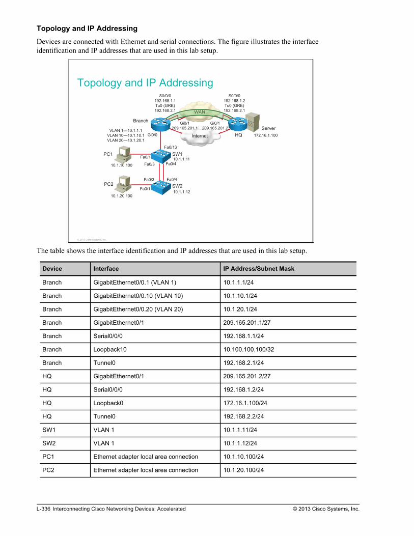
Topology and IP Addressing
Devices are connected with Ethernet and serial connections. The figure illustrates the interfaceidentification and IP addresses that are used in this lab setup.
Topology and IP Addressing
Internet
WAN
Server
PC1
PC2
SW1
SW2
Branch
HQ
Fa0/1
Fa0/1
Gi0/0
Fa0/13
Fa0/3 Fa0/4
Fa0/3 Fa0/4
Gi0/1
209.165.201.1
Gi0/1
209.165.201.2
S0/0/0
192.168.1.2
Tu0 (GRE)
192.168.2.1
S0/0/0
192.168.1.1
Tu0 (GRE)
192.168.2.1
10.1.10.100
10.1.20.100
10.1.1.11
10.1.1.12
VLAN 1—10.1.1.1
VLAN 10—10.1.10.1
VLAN 20—10.1.20.1
172.16.1.100
a0/3 Fa0
/3 Fa0
WWAWW N
© 2013 Cisco Systems, Inc.
The table shows the interface identification and IP addresses that are used in this lab setup.
Device Interface IP Address/Subnet Mask
Branch GigabitEthernet0/0.1 (VLAN 1) 10.1.1.1/24
Branch GigabitEthernet0/0.10 (VLAN 10) 10.1.10.1/24
Branch GigabitEthernet0/0.20 (VLAN 20) 10.1.20.1/24
Branch GigabitEthernet0/1 209.165.201.1/27
Branch Serial0/0/0 192.168.1.1/24
Branch Loopback10 10.100.100.100/32
Branch Tunnel0 192.168.2.1/24
HQ GigabitEthernet0/1 209.165.201.2/27
HQ Serial0/0/0 192.168.1.2/24
HQ Loopback0 172.16.1.100/24
HQ Tunnel0 192.168.2.2/24
SW1 VLAN 1 10.1.1.11/24
SW2 VLAN 1 10.1.1.12/24
PC1 Ethernet adapter local area connection 10.1.10.100/24
PC2 Ethernet adapter local area connection 10.1.20.100/24
L-336 Interconnecting Cisco Networking Devices: Accelerated © 2013 Cisco Systems, Inc.

Trunk and VLAN Setup
Three VLANs are configured on the switches. VLAN 1 is used for switch management, VLAN 10 is usedto connect PC1, and VLAN 20 is used to connect PC2. The two links between SW1 and SW2 are bondedinto an Etherchannel and a trunk is configured on it. SW1 switch and the Branch router are connected by atrunk link. The figure illustrates trunk and VLAN setup.
Trunk and VLAN Setup
© 2013 Cisco Systems, Inc.
© 2013 Cisco Systems, Inc. Lab Guide L-337

IP Routing
The HQ router has interfaces Serial0/0/0 and Loopback0 in OSPF Area 0. The Branch router has only theinterface Serial0/0/0 enabled in Area 0. All of the interfaces on the Branch router toward the LAN areenabled for OSPF Area 1. The HQ router ID is 1.1.1.1.
IP RoutingOSPF Area 1 OSPF Area 0
Branch HQ10.1.1.0/24
10.1.10.0/24
10.1.20.0/24
10.100.100.100/32
172.16.1.0/24
192.168.1.0/24192.168.1.0/24
© 2013 Cisco Systems, Inc.
Task 1: Configure Router for SNMP AccessIn this task, you will configure a community access string to permit SNMP access to the router.
Activity ProcedureComplete the following steps:
Step 1
On the Branch router, define the community access string "Cisco" with read-write privileges.
Step 2
On the Branch router, set the SNMP system contact string to "Joe Summer" and SNMP system locationstring to "San Jose."
L-338 Interconnecting Cisco Networking Devices: Accelerated © 2013 Cisco Systems, Inc.

Step 3
On PC1, run HillSoft MIB Browser. Click Tools >SNMP Entities and fill in the required fields to be ableto retrieve SNMP data from the Branch router.
Step 4
In the MIB tree view, navigate to iso->org->dod->internet->mgmt->mib-2->system.
Activity VerificationYou have completed this task when you attain this result:
© 2013 Cisco Systems, Inc. Lab Guide L-339

Step 1
Choose sysContact SNMP OID, choose GET as the SNMP method, and click the green button.
You should see that value for this OID is "Joe Summer."
Step 2
Repeat the same procedure for other OIDs (sysUpTime, sysName, sysLocation, and so on).
Task 2: Configure Router for SyslogIn this task, you will configure the Branch router to send syslog messages to the syslog server, which isinstalled on PC1.
Activity ProcedureComplete the following steps:
Step 1
On the Branch router, configure PC1 as the syslog server host that receives syslog messages.
Step 2
On the Branch router, specify that syslog messages with all severity levels are sent to the syslog server.
L-340 Interconnecting Cisco Networking Devices: Accelerated © 2013 Cisco Systems, Inc.

Step 3
Run Kiwi Syslog Daemon, which is installed on PC1.
Step 4
On the Branch router, disable the Serial0/0/0 interface.
Note By doing this, you will initiate the generation of syslog messages.
Step 5
After observing syslog messages on the Kiwi Syslog server, enable the Serial0/0/0 interface on the Branchrouter.
Step 6
Save the changes that you made on the Branch router.
Branch# copy running-config startup-config
Activity VerificationYou have completed this task when you attain these results:
Step 1
Observe the syslog messages that are received on the Kiwi Syslog server.
You should see the syslog message of the Serial0/0/0 interface going down and the message of OSPF stategoing from FULL to DOWN.
© 2013 Cisco Systems, Inc. Lab Guide L-341

Step 2
On the Branch router, display the state of syslog and the contents of the standard system logging buffer.
Branch# show loggingSyslog logging: enabled (0 messages dropped, 2 messages rate-limited, 0 flushes, 0 overruns, xml disabled, filtering disabled)No Active Message Discriminator.No Inactive Message Discriminator. Console logging: level debugging, 27 messages logged, xml disabled, filtering disabled Monitor logging: level debugging, 0 messages logged, xml disabled, filtering disabled Buffer logging: level debugging, 50 messages logged, xml disabled, filtering disabled Exception Logging: size (4096 bytes) Count and timestamp logging messages: disabled Persistent logging: disabled Trap logging: level debugging, 53 message lines logged Logging to 10.1.10.100 (udp port 514, audit disabled, link up), 23 message lines logged, 0 message lines rate-limited, 0 message lines dropped-by-MD, xml disabled, sequence number disabled filtering disabled Logging Source-Interface: VRF Name:<output omitted>
You should see that the syslog logging level is debugging and the syslog messages are sent to the serverwith IP address 10.1.10.100.
L-342 Interconnecting Cisco Networking Devices: Accelerated © 2013 Cisco Systems, Inc.

Lab 10-2: Analyzing NetFlowData
Activity OverviewObjectivesIn this activity, you will look at outputs from a NetFlow analyzer and answer questions about them. Aftercompleting this activity, you will be able to meet this objective:
Analyze data that is captured by the NetFlow Collector
Visual ObjectiveThere is no visual objective for this lab.
Required ResourcesNo additional resources are required for this lab.
Command ListThere are no commands that are needed for completing this lab.
Job AidsThere are no job aids that are needed for completing this lab.
Task 1: Analyze NetFlow DataIn this task, you analyze and interpret NetFlow data that is obtained in the NetFlow analyzer.
Activity ProcedureComplete the following steps:

Step 1
Which application is responsible for generating the most traffic in your network according to the followingpie chart?
The pie chart provides a view of the applications that are responsible for the most traffic passing throughthe viewed node or interface over the selected period of time. The table along with the pie chart providesthe following information:
The application name with its assigned port number
The amount of data, in both bytes and packets, flowing to the selected application through the viewednode
L-344 Interconnecting Cisco Networking Devices: Accelerated © 2013 Cisco Systems, Inc.

The percentage of all traffic through the viewed node that can be attributed to use of the listedapplication
Answer: _________________________________________________
© 2013 Cisco Systems, Inc. Lab Guide L-345

Step 2
Which is the most bandwidth-consuming conversation that is conducted over your monitored network?
The pie chart provides a list of the most bandwidth-consuming conversations that are conducted over yourmonitored network. Conversations are listed with the amount of data that is transferred in the conversation,in both bytes and packets. The table along with the pie chart provides the following information:
The application name
The amount of data, in both bytes and packets, flowing in the selected conversation through the viewednode or interface
The percentage of all traffic through the viewed node or interface
Answer: _________________________________________________
L-346 Interconnecting Cisco Networking Devices: Accelerated © 2013 Cisco Systems, Inc.

Step 3
Which receiver consumes the most bandwidth over your monitored network?
The pie chart provides a list of the receivers consuming the bandwidth over your monitored network.Receivers are listed with the amount of data that is transferred, in both bytes and packets, and the name orIP address of the receiving endpoint. The table along with the pie chart provides the following information:
The application name
The amount of data, in both bytes and packets, that is routed through the viewed node that is receivedby the listed endpoint over the specified period of time
The percentage of all traffic that is routed through the viewed node that is received by the listedendpoint over the specified period of time
Answer: _________________________________________________
© 2013 Cisco Systems, Inc. Lab Guide L-347

Step 4
Which transmitter consumes the most bandwidth over your monitored network?
The pie chart provides a list of the transmitters consuming the bandwidth over your monitored network.Transmitters are listed with the amount of data that is transferred, in both bytes and packets. The table alongwith the pie chart provides the following information:
The application name
The amount of data, in both bytes and packets, that is routed through the viewed node that is receivedby the listed endpoint over the specified period of time
The percentage of all traffic that is routed through the viewed node that is received by the listedendpoint over the specified period of time
Answer: _________________________________________________
L-348 Interconnecting Cisco Networking Devices: Accelerated © 2013 Cisco Systems, Inc.

Step 5
Which IP address group is responsible for the most traffic on your network?
The pie chart provides a view of the IP address groups that are responsible for the most traffic on yournetwork. With NetFlow, you can create IP groups that are based on IP addresses and/or a combination ofport and protocol. IP grouping is useful in tracking departmental bandwidth utilization, calculatingbandwidth costs, and ensuring appropriate usage of network bandwidth. The table along with the pie chartprovides the following information:
The IP address group range or the name of this IP range
The amount of data, in both bytes and packets, through the viewed node that is traceable to the listed IPaddress group over the selected period of time
The percentage of all traffic over the viewed node that is traceable to the listed IP address group
Answer: _________________________________________________
Activity VerificationNo additional verification is needed in this task.
© 2013 Cisco Systems, Inc. Lab Guide L-349

L-350 Interconnecting Cisco Networking Devices: Accelerated © 2013 Cisco Systems, Inc.

Lab 10-3: Managing CiscoDevices and Licensing
Activity OverviewObjectivesIn this lab, you will perform a password recovery, manage Cisco IOS image and configuration files, andverify licensing. After completing this activity, you will be able to meet these objectives:
Perform a password recovery on a router
Back up a Cisco IOS image
Manage configuration files
Verify licensing
Visual ObjectiveThe figure illustrates what you will accomplish in this activity.

Visual Objective for Lab 10-3: Managing CiscoDevices and Licensing
© 2013 Cisco Systems, Inc.
Detailed Visual Objective
© 2013 Cisco Systems, Inc.
Required ResourcesPC1 must have Cisco TFTP Server software installed.
Command ListThe table describes the commands that are used in this activity. The commands are listed in alphabeticalorder so that you can easily locate the information that you need. Refer to this list if you need configurationcommand assistance during the lab activity.
L-352 Interconnecting Cisco Networking Devices: Accelerated © 2013 Cisco Systems, Inc.

Command Description
configure terminal Activates the configuration mode from the terminal.
config-register value Sets the configuration register in privileged mode.
confreg value Sets the configuration register in the rommon mode.
copy running-config startup-config Saves the running configuration into the startup configuration.
copy running-config tftp: Copies the running configuration to the TFTP server.
copy startup-config running-config Brings and merges the startup configuration into the runningconfiguration.
copy tftp: running-config Copies the configuration on the TFTP server to the runningconfiguration.
disable Exits privileged EXEC mode.
enable Activates privileged EXEC mode. In privileged EXEC mode, morecommands are available. This command requires you to enter theenable password if one is configured.
enable secret password Configures the enable password in MD5-encrypted form.
exit Exits the router console.
hostname hostname Sets the system name, which forms part of the prompt.
ping ip_address Pings a destination IP address.
reload Restarts the switch and reloads the Cisco IOS operating systemand configuration.
reset Resets the router from rommon mode.
show ip interfaces brief Displays a brief summary of the IP information and status of aninterface.
show license Displays information about the Cisco IOS Software license.
show version Displays information about the currently loaded software, alongwith hardware and device information.
Job AidsThese job aids are available to help you complete the lab activity.
The table shows the hardware that is used in the lab and the operating system that is running on the devices.
Device Hardware Operating System
Branch Cisco 2901 Integrated Services Router c2900-universalk9-mz.SPA.152-4.M4
HQ Cisco 2901 Integrated Services Router c2900-universalk9-mz.SPA.152-4.M4
SW1 Catalyst 2960 Series Switch c2960-lanbasek9-mz.150-1.SE3
SW2 Catalyst 2960 Series Switch c2960-lanlitek9-mz.150-1.SE3
PC1 Any PC Microsoft Windows 7
PC2 Any PC Microsoft Windows 7
© 2013 Cisco Systems, Inc. Lab Guide L-353

There are no console or enable passwords that are set for the routers and switches in the initial lab setup.The table shows the usernames and passwords that are used to access PC1 and PC2.
Device Username Password
PC1 Administrator admin
PC2 Administrator admin
Topology and IP Addressing
Devices are connected with Ethernet and serial connections. The figure illustrates the interfaceidentification and IP addresses that are used in this lab setup.
Topology and IP Addressing
Internet
WAN
Server
PC1
PC2
SW1
SW2
Branch
HQ
Fa0/1
Fa0/1
Gi0/0
Fa0/13
Fa0/3 Fa0/4
Fa0/3 Fa0/4
Gi0/1
209.165.201.1
Gi0/1
209.165.201.2
S0/0/0
192.168.1.2
Tu0 (GRE)
192.168.2.1
S0/0/0
192.168.1.1
Tu0 (GRE)
192.168.2.1
10.1.10.100
10.1.20.100
10.1.1.11
10.1.1.12
VLAN 1—10.1.1.1
VLAN 10—10.1.10.1
VLAN 20—10.1.20.1
172.16.1.100
a0/3 Fa0
/3 Fa0
WWAWW N
© 2013 Cisco Systems, Inc.
The table shows the interface identification and IP addresses that are used in this lab setup.
Device Interface IP Address/Subnet Mask
Branch GigabitEthernet0/0.1 (VLAN 1) 10.1.1.1/24
Branch GigabitEthernet0/0.10 (VLAN 10) 10.1.10.1/24
Branch GigabitEthernet0/0.20 (VLAN 20) 10.1.20.1/24
Branch GigabitEthernet0/1 209.165.201.1/27
Branch Serial0/0/0 192.168.1.1/24
Branch Loopback10 10.100.100.100/32
Branch Tunnel0 192.168.2.1/24
HQ GigabitEthernet0/1 209.165.201.2/27
HQ Serial0/0/0 192.168.1.2/24
HQ Loopback0 172.16.1.100/24
L-354 Interconnecting Cisco Networking Devices: Accelerated © 2013 Cisco Systems, Inc.

Device Interface IP Address/Subnet Mask
HQ Tunnel0 192.168.2.2/24
SW1 VLAN 1 10.1.1.11/24
SW2 VLAN 1 10.1.1.12/24
PC1 Ethernet adapter local area connection 10.1.10.100/24
PC2 Ethernet adapter local area connection 10.1.20.100/24
Trunk and VLAN Setup
Three VLANs are configured on the switches. VLAN 1 is used for switch management, VLAN 10 is usedto connect PC1, and VLAN 20 is used to connect PC2. The two links between SW1 and SW2 are bondedinto an EtherChannel and a trunk is configured on it. The SW1 switch and the Branch router are connectedby a trunk link. The figure illustrates trunk and VLAN setup.
Trunk and VLAN Setup
© 2013 Cisco Systems, Inc.
© 2013 Cisco Systems, Inc. Lab Guide L-355

IP Routing
The HQ router has interfaces Serial0/0/0 and Loopback0 in OSPF Area 0. The Branch router has only theinterface Serial0/0/0 enabled in Area 0. All of the interfaces on the Branch router toward the LAN areenabled for OSPF Area 1. The HQ router ID is 1.1.1.1.
IP RoutingOSPF Area 1 OSPF Area 0
Branch HQ10.1.1.0/24
10.1.10.0/24
10.1.20.0/24
10.100.100.100/32
172.16.1.0/24
192.168.1.0/24192.168.1.0/24
© 2013 Cisco Systems, Inc.
Task 1: Lab SetupIn this task, you will load a configuration onto the Branch router to create a trouble ticket. You will resolvethese tickets in the next tasks.
Activity ProcedureComplete the following steps:
Step 1
Access the Branch router.
Step 2
Overwrite the running configuration with the file located in the router flash memory calledINIT_Managing_and_Licensing_Branch.cfg.
Branch#configure replace flash: INIT_Managing_and_Licensing_Branch.cfg
Activity VerificationNo additional verification is needed in this task.
L-356 Interconnecting Cisco Networking Devices: Accelerated © 2013 Cisco Systems, Inc.

Task 2: Router Password RecoveryYou are unable to access the Branch router, because the enable password is misconfigured. In this task, youwill perform password recovery on the Branch router.
Activity ProcedureComplete the following steps:
Step 1
Connect with the console to the Branch router, and try to access privileged mode.
Branch con0 is now availablePress RETURN to get started.Branch>Branch>enablePassword:ciscoPassword:
You will see the user mode prompt, but you will be unable to access privileged mode, because you do nothave the proper enable password.
Step 2
On the Branch router, perform a password recovery so that you can access privileged mode.
Step 3
After completing the password recovery process, all of the interfaces on the router will be in theadministratively shutdown state.
Branch#show ip interface briefInterface IP-Address OK? Method Status ProtocolEmbedded-Service-Engine0/0 unassigned YES unset administratively down downGigabitEthernet0/0 unassigned YES unset administratively down downGigabitEthernet0/0.1 10.1.1.1 YES TFTP administratively down downGigabitEthernet0/0.10 10.1.10.1 YES TFTP administratively down downGigabitEthernet0/0.20 10.1.20.1 YES TFTP administratively down downGigabitEthernet0/1 209.165.201.1 YES TFTP administratively down downSerial0/0/0 192.168.1.1 YES TFTP administratively down downLoopback10 10.100.100.100 YES TFTP up upTunnel0 192.168.2.1 YES TFTP up down
Bring up interfaces Serial0/0/0, GigabitEthernet0/0, and GigabitEthernet0/1.
© 2013 Cisco Systems, Inc. Lab Guide L-357

Activity Verification
Step 1
On the Branch router, exit privileged mode and try to re-enter with the password cisco:
Branch#disable Branch>enable Password:ciscoBranch#
You should be able to access Branch router privileged mode.
Step 2
On the Branch router, verify the value of the configuration register:
Branch#show version | include registerConfiguration register is 0x2142 (will be 0x2102 at next reload)
The configuration register will be 0x2102 at the next reload.
Step 3
Verify that for interfaces Serial0/0/0, GigabitEthernet0/0.1, GigabitEthernet0/0.10, andGigabitEthernet0/0.20, the status is up/up.
Branch#sh ip interfaces briefInterface IP-Address OK? Method Status ProtocolEmbedded-Service-Engine0/0 unassigned YES unset administratively down downGigabitEthernet0/0 unassigned YES unset up upGigabitEthernet0/0.1 10.1.1.1 YES TFTP up upGigabitEthernet0/0.10 10.1.10.1 YES TFTP up upGigabitEthernet0/0.20 10.1.20.1 YES TFTP up upGigabitEthernet0/1 209.165.201.1 YES TFTP up upSerial0/0/0 192.168.1.1 YES TFTP up upLoopback10 10.100.100.100 YES TFTP up upTunnel0 192.168.2.1 YES TFTP up up
Task 3: Backing Up a Cisco IOS ImageIn this task, you will copy an IOS image from the Branch router to the TFTP server installed on PC1.
Activity ProcedureComplete the following steps:
Step 1
On the Branch router, confirm the presence of the IOS image on the flash.
L-358 Interconnecting Cisco Networking Devices: Accelerated © 2013 Cisco Systems, Inc.

Step 2
Verify connectivity from the Branch router to PC1. You should have connectivity between the two devices.
Branch#ping 10.1.10.100 Type escape sequence to abort.Sending 5, 100-byte ICMP Echos to 10.1.10.100, timeout is 2 seconds:!!!!!Success rate is 100 percent (5/5), round-trip min/avg/max = 56/56/56 ms
Step 3
On the desktop of PC1, create a new folder named TFTP.
Run the Cisco TFTP Server software on PC1. Select the Options > Server Root directory and set the rootdirectory of the TFTP server to the folder you just created.
Step 4
On the Branch router, enter the sequence of commands that will back up its Cisco IOS image to the TFTPserver.
Activity VerificationYou have completed this task when you attain this result:
© 2013 Cisco Systems, Inc. Lab Guide L-359

Step 1
Verify that the IOS image was copied to C:\TFTP on PC1.
You should see the image file in the TFTP folder.
Task 4: Manage the Configuration FileIn this task, you will copy the configuration file from the Branch router to the TFTP server on PC1. Youwill open the configuration file and change it on PC1, and apply the changed configuration to the Branchrouter.
Activity ProcedureComplete the following steps:
Step 1
Copy the running configuration of the Branch router to the TFTP server on PC1.
L-360 Interconnecting Cisco Networking Devices: Accelerated © 2013 Cisco Systems, Inc.

Step 2
On PC1, open the transferred file C:\TFTP\branch-confg using WordPad and change the host name toBranch-changedconfiguration. Save and close the file.
Step 3
Copy the changed configuration from the TFTP server on PC1 to the running configuration of the Branchrouter.
Will the new configuration overwrite the old one?
Step 4
Verify that the host name of the router has changed.
Branch-changedconfiguration#
Step 5
Change the host name of the Branch router back to Branch.
© 2013 Cisco Systems, Inc. Lab Guide L-361

Step 6
Save the changes you made on the Branch router.
Activity VerificationNo additional verification is needed for this activity.
Task 5: Verify LicensingIn this task, you will verify which technology package licenses are installed on the Branch router.
Activity ProcedureComplete the following steps:
Step 1
Verify which technology package licenses or feature licenses are installed on the Branch router.
Which technology package license is installed and what license type is this?__________________________________________________________________
Activity VerificationNo additional verification is needed for this activity.
L-362 Interconnecting Cisco Networking Devices: Accelerated © 2013 Cisco Systems, Inc.

Lab Answer Keys
Lab 1-1: Performing Switch Startup and InitialConfiguration
Task 1: Perform a Reload and Verify that the Switch IsUnconfigured
Step 2
Since the erase startup-config command is a privileged-level command, entering it in user EXEC modewill have no effect on the system. You were informed that the command is invalid.
Switch>erase startup-config ^% Invalid input detected at '^' marker.
Step 3
When you have a right arrow (>) symbol after the device hostname, you are in user EXEC mode. When youissued the enable command, you moved into privileged EXEC mode, which is indicated by the pound sign(#) after the hostname. Enter privileged EXEC mode by typing enable in user EXEC mode.
Switch>enableSwitch#
Step 4
When you enter the erase startup-config command within privileged EXEC mode, it is accepted and youare prompted to press Enter to confirm this action.

SwitchX#delete vlan.datDelete filename [vlan.dat]? Delete flash:/vlan.dat? [confirm]Switch#erase startup-configErasing the nvram filesystem will remove all configuration files! Continue? [confirm][OK]Erase of nvram: complete
When you enter the reload command within privileged EXEC mode, you are asked to confirm the reload.Press Enter at that point.
Switch#reloadProceed with reload? [confirm]*Mar 1 00:16:18.229: %SYS-5-RELOAD: Reload requested by console. Reload Reason: Reload command.Boot Sector Filesystem (bs) installed, fsid: 2Base ethernet MAC Address: 00:1e:14:7c:bd:00Xmodem file system is available.The password-recovery mechanism is enabled.Initializing Flash...flashfs[0]: 549 files, 19 directoriesflashfs[0]: 0 orphaned files, 0 orphaned directoriesflashfs[0]: Total bytes: 32514048flashfs[0]: Bytes used: 14942208flashfs[0]: Bytes available: 17571840flashfs[0]: flashfs fsck took 11 seconds....done Initializing Flash.done.Loading "flash:/c2960-lanbasek9-mz.150-1.SE3/c2960-lanbasek9-mz.150-1.SE3.bin"... @@@@@@@@@@@@@@@@@@@@@@@@@@@@@@@@@@@@@@@@@@@@@@@@@@@@@@@@@@@@@@@@@@@@@@@@@@@@@@@@@@@@@@@@@@@@@@@@@@@@@@@@@@@@@@@@@@@@@@@@@@@@@@@@@@@@<… output omitted …>64K bytes of flash-simulated non-volatile configuration memory.Base ethernet MAC Address : 00:1E:14:7C:BD:00Motherboard assembly number : 73-10390-04Power supply part number : 341-0097-02Motherboard serial number : FOC114131RVPower supply serial number : AZS113600YMModel revision number : D0Motherboard revision number : A0Model number : WS-C2960-24TT-LSystem serial number : FOC1141Z8W9Top Assembly Part Number : 800-27221-03Top Assembly Revision Number : B0Version ID : V03CLEI Code Number : COM3L00BRBHardware Board Revision Number : 0x01Switch Ports Model SW Version SW Image------ ----- ----- ---------- ----------* 1 26 WS-C2960-24TT-L 15.0(1)SE3 C2960-LANBASEK9-MPress RETURN to get started!
Step 5
Your results should resemble the output displayed here. You should have answered No to the question(Would you like to enter the initial configuration dialog?).
L-364 Interconnecting Cisco Networking Devices: Accelerated © 2013 Cisco Systems, Inc.

--- System Configuration Dialog ---Would you like to enter the initial configuration dialog? [yes/no]: noSwitch>
If you skipped the initial configuration dialog, there is no startup configuration present. Alternatively, youcan verify that there is no configuration present by entering privileged EXEC mode and issuing the showstartup-config command.
Switch>enableSwitch#show startup-configstartup-config is not present
Step 6
You can issue the show version command from either user or privileged EXEC mode. In the output here,you see that the switch is a WS-C2960-24TT-L type, the software version is 15.0(1)SE3, and there is 65536KB (or 64 MB) of RAM.Note that your device may have different properties.
Switch#show versionCisco IOS Software, C2960 Software (C2960-LANBASEK9-M), Version 15.0(1)SE3, RELEASE SOFTWARE (fc1)Technical Support: http://www.cisco.com/techsupportCopyright (c) 1986-2012 by Cisco Systems, Inc.Compiled Wed 30-May-12 14:26 by prod_rel_teamROM: Bootstrap program is C2960 boot loaderBOOTLDR: C2960 Boot Loader (C2960-HBOOT-M) Version 12.2(44)SE6, RELEASE SOFTWARE (fc1)Switch1 uptime is 4 hours, 31 minutesSystem returned to ROM by power-onSystem restarted at 09:25:53 UTC Fri Aug 17 2012System image file is "flash:/c2960-lanbasek9-mz.150-1.SE3/c2960-lanbasek9-mz.150-1.SE3.bin"This product contains cryptographic features and is subject to UnitedStates and local country laws governing import, export, transfer anduse. Delivery of Cisco cryptographic products does not implythird-party authority to import, export, distribute or use encryption.Importers, exporters, distributors and users are responsible forcompliance with U.S. and local country laws. By using this product youagree to comply with applicable laws and regulations. If you are unableto comply with U.S. and local laws, return this product immediately.A summary of U.S. laws governing Cisco cryptographic products may be found at:http://www.cisco.com/wwl/export/crypto/tool/stqrg.htmlIf you require further assistance please contact us by sending email [email protected] WS-C2960-24TT-L (PowerPC405) processor (revision D0) with 65536K bytes of memory.<… output omitted …>
The show flash: command output here shows that the switch has 32514048 bytes (32 MB) of flash memoryand that 17569280 bytes of that memory is free (16.8 MB).
Note that your device may have different properties.
© 2013 Cisco Systems, Inc. Lab Guide L-365

Switch#show flashDirectory of flash:/ 2 drwx 256 Aug 8 2012 12:23:45 +00:00 c2960-lanbasek9-mz.150-1.SE3 567 -rwx 556 Nov 21 2012 08:17:08 +00:00 vlan.dat 568 -rwx 2072 Nov 21 2012 11:05:33 +00:00 multiple-fs32514048 bytes total (17573376 bytes free)
Task 2: Configure the Switch with a Hostname and an IPAddress
Step 1
Enter privileged EXEC mode and then global configuration mode. Issue the hostname command, as shownin the following output. Notice the change in the hostname of the device in the last line of the output.
Switch#enableSwitch#configure terminalEnter configuration commands, one per line. End with CNTL/Z.Switch(config)#hostname SW1SW1(config)#
Step 2
First, make sure that you are in global configuration mode.
SW1(config)#
Then enter interface configuration mode for VLAN 1 and assign it the proper IP address and network mask.
SW1(config)#interface vlan 1SW1(config-if)#ip address 10.1.1.11 255.255.255.0
Step 5
On PC1, click the Start button, enter cmd, and click Enter. When you are presented with a commandprompt window, enter ping, followed by the IP address of the VLAN 1 interface on the switch. This Layer3 test should succeed.
L-366 Interconnecting Cisco Networking Devices: Accelerated © 2013 Cisco Systems, Inc.

Task 3: Explore Context-Sensitive Help
Step 1
After you enter privileged EXEC mode and enter ?, you are presented with a list of available commands.Each command is listed with a description.
SW1>enableSW1#?Exec commands: access-enable Create a temporary Access-List entry access-profile Apply user-profile to interface access-template Create a temporary Access-List entry archive manage archive files beep Blocks Extensible Exchange Protocol commands<… output omitted …> where List active connections write Write running configuration to memory, network, or terminal
Step 2
First, make sure that you are in privileged EXEC mode. Enter clock, followed by ?. Complete theconfiguration as displayed here.
SW1#clock ? set Set the time and dateSW1#clock set ? hh:mm:ss Current TimeSW1#clock set 12:57:22 ? <1-31> Day of the month MONTH Month of the yearSW1#clock set 12:57:22 17 ? MONTH Month of the yearSW1#clock set 12:57:22 17 8 ?% Unrecognized commandLan_Switch_1#clock set 12:57:22 17 August ? <1993-2035> YearSW1#clock set 12:57:22 17 August 2012 ? <cr>SW1#clock set 12:57:22 17 August 2012
Step 3
When you are familiar only with how a command begins, you can get help by using the ? command. It willlist all commands that begin with the sequence of letters that you entered.
© 2013 Cisco Systems, Inc. Lab Guide L-367

SW1#sh?shell showSW1#show ? aaa Show AAA values access-lists List access lists aliases Display alias commands archive Archive functions arp ARP table authentication Shows Auth Manager registrations or sessions auto Show Automation Template beep Show BEEP information boot show boot attributes buffers Buffer pool statistics cable-diagnostics Show Cable Diagnostics Results call-home Show command for call home capability Capability Information cca CCA information cdp CDP information cisp Shows CISP information class-map Show CPL Class Map clock Display the system clock cluster Cluster information cns CNS agents configuration Contents of Non-Volatile memory controllers Interface controller status crypto Encryption moduleSW1#show clock?clockSW1#show clock13:01:24.145 UTC Fri Aug 17 2012
Task 4: Improve the Usability of the CLI
Step 1
You can enter the show terminal command and then investigate the output to determine the current historysize. Alternatively, you can use the pipe (|) along with the include command and the keyword history sizeto print out just the line with the information.
SW1>show terminal | include history sizeHistory is enabled, history size is 20.
Step 2
Enter global configuration mode.
SW1#configure terminalEnter configuration commands, one per line. End with CNTL/Z.
Enter line console 0 configuration mode.
SW1(config)#line console 0
L-368 Interconnecting Cisco Networking Devices: Accelerated © 2013 Cisco Systems, Inc.

Change the history size to 100.
SW1(config-line)#history size 100
Issue the exit command twice to get back to privileged EXEC mode.
SW1(config-line)#exitSW1(config)#exit
Verify that the history size is changed.
SW1#show terminal | i history sizeHistory is enabled, history size is 100.
Step 3
You must be in global configuration mode before issuing the no ip domain lookup command.
SW1>enableSW1#configure terminalSW1(config)#no ip domain-lookup
Step 4
Issue the exec-timeout 60 command to set the console timeout expiration timer to one hour.
SW1(config-line)#exec-timeout 60
Verify that idle exec timeout is set to one hour. Use the verification command directly from consoleconfiguration mode.
SW1(config-line)#do show terminal | begin TimeoutsTimeouts: Idle EXEC Idle Session Modem Answer Session Dispatch 01:00:00 never none not set<output omitted>SW1(config-line)#exit
Step 5
Make sure that you are in global configuration mode and then enter line console 0 configuration mode. Last,enable synchronous logging as shown in the output here.
SW1(config)#line console 0SW1(config-line)#logging synchronousSW1(config-line)#exitSW1(config)#exit
© 2013 Cisco Systems, Inc. Lab Guide L-369

Step 6
This command copies the running configuration to the startup configuration. If you do not save theconfiguration, you will lose it the next time the switch is restarted.
SW1#copy running-config startup-config
If you press Enter when asked for the destination filename, the running configuration is stored as thestartup configuration.
Destination filename [startup-config]?Building configuration...[OK]
Lab 1-2: Troubleshooting Switch Media Issues
Task 2: Troubleshoot Connectivity Between Computer PC1and Switch SW1
Step 1
When you issue a ping from SW1 to PC1, your success rate is 0 percent, so there is no Layer 3 connectivitybetween the two devices.
SW1>ping 10.1.1.100Type escape sequence to abort.Sending 5, 100-byte ICMP Echos to 10.1.1.11, timeout is 2 seconds:.....Success rate is 0 percent (0/5)
Step 2
The output of the show interfaces FastEthernet0/1 command tells you that the interface toward PC1 isadministratively down, which means that the interface was disabled by the administrator.
SW1>enableSW1#show interfaces FastEthernet0/1FastEthernet0/1 is administratively down, line protocol is down (disabled) Hardware is Fast Ethernet, address is 001e.147c.bd01 (bia 001e.147c.bd01) MTU 1500 bytes, BW 10000 Kbit/sec, DLY 1000 usec, reliability 255/255, txload 1/255, rxload 1/255 Encapsulation ARPA, loopback not set Keepalive set (10 sec) Auto-duplex, Auto-speed, media type is 10/100BaseTX
L-370 Interconnecting Cisco Networking Devices: Accelerated © 2013 Cisco Systems, Inc.

Step 3
Enter global configuration mode.
SW1#configure terminalEnter configuration commands, one per line. End with CTRL-Z.
Enter interface configuration mode for FastEthernet 0/1 and enable the interface with the no shutdowncommand.
SW1(config)#interface FastEthernet 0/1SW1(config-if)#no shutdown
Finally, verify Layer 3 connectivity between PC1 and SW1 by issuing a ping command. It should besuccessful.
SW1#ping 10.1.1.100Type escape sequence to abort.Sending 5, 100-byte ICMP Echos to 10.1.1.100, timeout is 2 seconds:!!!!!Success rate is 100 percent (5/5), round-trip min/avg/max = 1/5/9 ms
Step 4
It is important to save the configuration of SW1 because the no shutdown command would disappear if theswitch is restarted. John would again be cut off from the network.
SW1#copy running-config startup-config
Task 3: Troubleshoot Connectivity Between Switch SW1 andthe Branch Router
Step 1
Because you have console logging enabled (which you can verify with the show logging command), theswitch is reporting. This message tells you that the interfaces of SW1 and Branch have different duplexsettings. It looks like the Branch router FastEthernet0/0 interface is configured for full duplex, whileinterface FastEthernet0/13 on the switch is not configured for full duplex.
Aug 21 14:39:52.112: %CDP-4-DUPLEX_MISMATCH: duplex mismatch discovered on FastEthernet0/13 (not full duplex), with Branch FastEthernet0/0 (full duplex).
Use the show interfaces FastEthernet Fa0/13 command to identify the duplex setting on the interface.
© 2013 Cisco Systems, Inc. Lab Guide L-371

SW1#show interfaces FastEthernet 0/13FastEthernet 0/13 is up, line protocol is up (connected) Hardware is Fast Ethernet, address is 001e.147c.bd0d (bia 001e.147c.bd0d) MTU 1500 bytes, BW 100000 Kbit/sec, DLY 100 usec, reliability 255/255, txload 1/255, rxload 1/255 Encapsulation ARPA, loopback not set Keepalive set (10 sec) Half-duplex, 100Mb/s, media type is 10/100BaseTX input flow-control is off, output flow-control is unsupported<… output omitted …>
You can also use the show ip interface brief command to verify status of all interfaces. It shows thatinterface FastEthernet 0/13 is in an up/up state. This status means that even though the duplex settings aremismatched on the link, it is still functional. The drawback is that the connection is not efficient. With half-duplex operation, data cannot be sent and received at the same time.
SW1#show ip interface briefInterface IP-Address OK? Method Status Protocol<… output omitted …>FastEthernet0/13 unassigned YES unset up up<output omitted>
Step 2
Enter global configuration mode.
SW1#configure terminalEnter configuration commands, one per line. End with CTRL-Z.
Enter interface configuration mode.
SW1(config)#interface FastEthernet 0/13
Change the duplex setting to full.
SW1(config-if)#duplex full
Save your changes by copying the running configuration to the startup configuration.
SW1(config)#interface FastEthernet 0/13SW1(config-if)#endSW1#copy run startDestination filename [startup-config]?Building configuration...[OK]
L-372 Interconnecting Cisco Networking Devices: Accelerated © 2013 Cisco Systems, Inc.

Lab 2-1: Performing Initial Router Setup andConfiguration
Task 1: Inspect the Router Hardware and Software
Step 1
Enter this command on the Branch router:
Router>enableRouter#
Task 2: Create the Initial Router Configuration
Step 1
Answer No to the initial configuration dialog question and use the enable command to enter privilegedEXEC mode.
Would you like to enter the initial configuration dialog? [yes/no]: noWould you like to terminate autoinstall? [yes]: <output omitted>Router>Router>enableRouter#
Step 2
Use the command hostname to set the hostname.
Router(config)#Router(config)#hostname BranchBranch(config)#
Step 3
Enter these commands on the Branch router to enter interface configuration mode, enable the interface, andprovide a description:
Branch(config)#interface GigabitEthernet 0/0Branch(config-if)#no shutdown%LINK-3-UPDOWN: Interface GigabitEthernet0/0, changed state to down%LINK-3-UPDOWN: Interface GigabitEthernet0/0, changed state to up%LINEPROTO-5-UPDOWN: Line protocol on Interface GigabitEthernet0/0, changed state to upBranch(config-if)#description Link to LAN Switch
© 2013 Cisco Systems, Inc. Lab Guide L-373

Step 4
Enter this command on the Branch router:
Branch(config-if)#ip address 10.1.1.1 255.255.255.0
Step 6
Use this command on the Branch router:
Branch#copy running-config startup-configDestination filename [startup-config]?Building configuration...[OK]Branch#
Task 3: Improve the Usability of the CLI
Step 1
Enter these commands on the Branch router:
Branch#configure terminalBranch(config)#line console 0Branch(config-line)#exec-timeout 60 0
Step 3
Use the logging synchronous command on the Branch router:
Branch(config-line)#logging synchronous
Step 4
On the Branch router, use the command no ip domain lookup in global configuration mode to disable theresolution of symbolic names.
Branch(config)#no ip domain lookup
Step 5
On the Branch router, use the command write memory to copy the configuration into NVRAM.
Branch#write memory
L-374 Interconnecting Cisco Networking Devices: Accelerated © 2013 Cisco Systems, Inc.

Lab 2-2: Connecting to the Internet
Task 1: Configure a Manual IP Address and Static DefaultRoute
Step 3
Enter the following commands on the Branch router:
Branch(config)#interface GigabitEthernet0/1Branch(config-if)#no shutdownBranch(config-if)#ip address 209.165.201.1 255.255.255.224
Step 6
The Branch router does not have a route to reach networks that are not directly connected.
Step 7
No, there is no route present for the IP address of the server.
Step 8
Enter the following command on the Branch router:
Branch#configure terminalBranch(config)#ip route 0.0.0.0 0.0.0.0 209.165.201.2
Step 9
Enter the following commands on the Branch router:
Branch(config)#exitBranch#copy running-config startup-config
Step 12
Enter the following command on the Branch router:
Branch(config)#no ip route 0.0.0.0 0.0.0.0 209.165.201.2
Task 2: Configure a DHCP-Obtained IP Address
© 2013 Cisco Systems, Inc. Lab Guide L-375

Step 2
Enter the following commands on the Branch router:
Branch(config-if)#interface GigabitEthernet0/1Branch(config-if)#ip address dhcp
Step 3
Enter the following commands on the Branch router:
Branch(config-if)#exitBranch(config)#exitBranch#copy running-config startup-config
Step 5
The default route was set by the Branch router automatically. The Branch router received knowledge of thedefault gateway from the DHCP server and it set the static route next-hop IP address to the IP address of thedefault gateway.
Step 12
The solution that could be implemented on the Branch router to provide connectivity between PC1 and theserver is NAT. With NAT, the source IP address in a packet would be translated into the outside IP addressof the Branch router. The HQ router would then know how to send a returning packet back to the Branchrouter, because the routers are directly connected. The destination IP address in the packet would be thentranslated back to the IP address of PC1 and sent to PC1.
Task 3: Configure NAT
Step 2
Enter the following command on the Branch router:
Branch(config)#access-list 1 permit 10.1.1.0 0.0.0.255
Step 3
Enter the following commands on the Branch router:
Branch(config)#ip nat pool NAT_POOL 209.165.201.5 209.165.201.10 netmask 255.255.255.224
L-376 Interconnecting Cisco Networking Devices: Accelerated © 2013 Cisco Systems, Inc.

You can accommodate up to six hosts at the same time using the configured NAT pool.
Step 4
Enter the following commands on the Branch router:
Branch(config)#interface GigabitEthernet0/0Branch(config-if)#ip nat inside
Step 5
Enter the following commands on the Branch router:
Branch(config)#interface GigabitEthernet0/1Branch(config-if)#ip nat outside
Step 6
Enter the following command on the Branch router:
Branch(config)#ip nat inside source list 1 pool NAT_POOL
Step 7
Enter the following commands on the Branch router:
Branch(config)#exitBranch#copy running-config startup-config
Task 4: Configure NAT with PAT
Step 2
Enter the following command on the Branch router:
Branch(config)#no ip nat inside source list 1 pool NAT_POOLDynamic mapping in use, do you want to delete all entries? [no]: yes
Step 3
Enter the following command on the Branch router (and then answer with yes):
Branch(config)#ip nat inside source list 1 interface GigabitEthernet0/1 overload
© 2013 Cisco Systems, Inc. Lab Guide L-377

You can accommodate approximately 64,000 hosts by overloading one IP address.
Step 4
Enter the following commands on the Branch router:
Branch(config)#exitBranch#copy running-config startup-config
Lab 3-1: Enhancing the Security of the InitialConfiguration
Task 1: Add Password Protection
Step 2
Enter this sequence of commands into the Branch router:
Branch> enableBranch# configure terminalBranch(config)# line console 0Branch(config-line)# password cisco Branch(config-line)# login
Step 5
Enter the following command sequence into the Branch router:
Branch(config)# username ccna secret ciscoBranch(config)# line console 0Branch(config-line)# login local
Step 8
Enter this sequence of commands into the Branch router:
Branch(config)# line vty 0 15Branch(config-line)# login local
Step 10
Enter this command on the Branch router:
Branch(config)# enable secret cisco
L-378 Interconnecting Cisco Networking Devices: Accelerated © 2013 Cisco Systems, Inc.

Step 11
Enter this command on the Branch router:
Branch# copy running-config startup-config
Step 14
Enter this sequence of commands on SW1:
SW1(config)# enable secret ciscoSW1(config)# username ccna secret ciscoSW1(config)# line console 0SW1(config-line)# login localSW1(config-line)# line vty 0 15SW1(config-line)# login local
Step 15
Enter this command on the SW1 switch:
SW1# copy running-config startup-config
Task 2: Enable SSH Remote Access
Step 1
Enter this sequence of commands on the Branch router:
Branch(config)# ip domain-name cisco.comBranch(config)# crypto key generate rsaThe name for the keys will be: Branch.cisco.comChoose the size of the key modulus in the range of 360 to 2048 for your General Purpose Keys. Choosing a key modulus greater than 512 may take a few minutes.How many bits in the modulus [512]: 1024% Generating 1024 bit RSA keys, keys will be non-exportable...[OK]Branch(config)# line vty 0 15Branch(config-line)# transport input sshBranch(config-line)# exitBranch(config)# ip ssh version 2
Step 2
Enter this command on the Branch router:
Branch# copy running-config startup-config
© 2013 Cisco Systems, Inc. Lab Guide L-379

Step 3
Enter this sequence of commands on the SW1 switch:
SW1(config)# ip domain-name cisco.comSW1(config)# crypto key generate rsaThe name for the keys will be: SW1.cisco.comChoose the size of the key modulus in the range of 360 to 2048 for your General Purpose Keys. Choosing a key modulus greater than 512 may take a few minutes.How many bits in the modulus [512]: 1024% Generating 1024 bit RSA keys, keys will be non-exportable...[OK]SW1(config)# line vty 0 15SW1(config-line)# transport input sshSW1(config-line)# ip ssh version 2
Step 4
Enter this command on the SW1 switch:
SW1# copy running-config startup-config
Task 3: Limit Remote Access to Selected Network Addresses
Step 1
Enter this sequence of commands on the SW1 switch:
SW1(config)# access-list 1 permit host 10.1.1.1SW1(config)# access-list 1 deny any log
Step 3
Enter this command on the SW1 switch:
SW1# copy running-config startup-config
Task 4: Configure a Login Banner
Step 1
Enter the following command on the Branch router:
Branch(config)# banner login #********** Warning *************Enter TEXT message. End with the character '#'.Access to this device is restricted to authorized persons only!Unauthorized access is prohibited. Violators will be prosecuted.***********************************************#
L-380 Interconnecting Cisco Networking Devices: Accelerated © 2013 Cisco Systems, Inc.

Step 2
Enter this command on the Branch router:
Branch# copy running-config startup-config
Step 3
Enter the following command on the SW1 switch:
SW1(config)# banner login #********** Warning *************Enter TEXT message. End with the character '#'.Access to this device is restricted to authorized persons only!Unauthorized access is prohibited. Violators will be prosecuted.***********************************************#
Step 4
Enter this command on the SW1 switch:
SW1# copy running-config startup-config
Lab 3-2: Device Hardening
Task 1: Disable Unused Ports
Step 2
Enter this sequence of commands into the SW1 switch:
SW1(config)# interface range FastEthernet 0/14 - 24SW1(config-if-range)# shutdown
Step 4
Enter the following commands on the SW1 switch:
SW1# copy running-config startup-config
Task 2: Configure Port Security on a Switch
© 2013 Cisco Systems, Inc. Lab Guide L-381

Step 4
Enter these commands on the SW1 switch:
SW1(config)# interface FastEthernet 0/13SW1(config-if)# switchport mode access
Step 5
Enter this sequence of commands into the SW1 switch:
SW1(config-if)# switchport port-security mac-address f866.f231.7251SW1(config-if)# switchport port-security
Step 8
Enter this sequence of commands into the SW1 switch:
SW1(config-if)# no switchport port-security mac-address f866.f231.7251SW1(config-if)# switchport port-security mac-address f866.f231.7250
Step 9
Enter this sequence of commands into the SW1 switch:
SW1(config-if)# shutdownSW1(config-if)# no shutdown
Step 14
Enter this command into the SW1 switch:
SW1(config-if)# no switchport port-security
Step 15
Enter the following command on the SW1 switch:
SW1# copy running-config startup-config
Task 3: Disable Unused Services
L-382 Interconnecting Cisco Networking Devices: Accelerated © 2013 Cisco Systems, Inc.

Step 3
Enter this sequence of commands into the switch.
SW1(config)# interface FastEthernet 0/13SW1(config-if)# no cdp enable
Step 6
Enter this sequence of commands into the switch.
SW1(config)# interface FastEthernet 0/13SW1(config-if)# cdp enable
Step 7
Enter the following command on the SW1 switch:
SW1# copy running-config startup-config
Task 4: Configure NTP
Step 1
Enter the following command on the Branch router:
Branch(config)# ntp server 172.16.1.100
Step 3
The stratum of the clock on the Branch router is 4.
Step 5
Enter the following command on the SW1 switch:
SW1(config)# ntp server 10.1.1.1
Step 6
The stratum of the clock on the SW1 switch is 5.
© 2013 Cisco Systems, Inc. Lab Guide L-383

Step 7
Enter the following commands on the SW1 switch and Branch router:
SW1# copy running-config startup-config
Branch# copy running-config startup-config
Lab 3-3: Filtering Traffic with ACLs
Task 1: Configure an ACL
Step 2
Enter this sequence of commands into the Branch router:
Branch(config)# ip access-list extended TelnetBranch(config-ext-nacl)# deny tcp host 10.1.1.101 host 172.16.1.100 eq telnetBranch(config-ext-nacl)# permit ip any any
Step 4
Enter this sequence of commands into the Branch router:
Branch(config)# interface GigabitEthernet 0/0Branch(config-if)# ip access-group Telnet in
Step 6
Enter the following command on the Branch router:
Branch# copy running-config startup-config
Task 3: Troubleshoot an ACL
Step 7
Enter this sequence of commands into the Branch router:
Branch(config)# interface GigabitEthernet 0/0Branch(config-if)# no ip access-group outBranch(config-if)# ip access-group in
L-384 Interconnecting Cisco Networking Devices: Accelerated © 2013 Cisco Systems, Inc.

Step 9
Enter this sequence of commands into the Branch router:
Branch(config)# ip access-list extended TelnetBranch(config-ext-nacl)# no 10Branch(config-ext-nacl)# no 20Branch(config-ext-nacl)# 40 permit ip any any
Step 10
Enter the following command on the Branch router:
Branch# copy running-config startup-config
Lab 4-1: Configure and Verify Basic IPv6
Task 1: Enable IPv6 on the Router
Step 1
Enter this command on the Branch router:
Branch(config)# ipv6 unicast-routing
Step 2
Enter these commands on the Branch router:
Branch(config)# interface GigabitEthernet 0/1Branch(config-if)# ipv6 address 2001:db8:D1A5:C900::1/64
Step 3
Enter the following command on the Branch router:
Branch# copy running-config startup-config
© 2013 Cisco Systems, Inc. Lab Guide L-385

Lab 4-2: Configure and Verify StatelessAutoconfiguration
Task 1: Enable Stateless Autoconfiguration on the Router
Step 2
Enter these commands on the Branch router:
Branch(config)#interface GigabitEthernet 0/1Branch(config-if)#no ipv6 address 2001:DB8:D1A5:C900::1/64
Step 3
Enter these commands on the Branch router:
Branch(config)#interface GigabitEthernet 0/1 Branch(config-if)#ipv6 address autoconfig
Lab 4-3: Configure and Verify IPv6 Routing
Task 1: Task: Enable IPv6 Static Routing
Step 3
Enter this command on the Branch router:
Branch(config)#ipv6 route ::/0 Gi0/1 2001:DB8:D1A5:C900::2
Lab 5-1: Configuring Expanded SwitchedNetworks
Task 1: Configure a VLAN
Step 1
Enter this sequence of commands on SW1:
SW2# configure terminalSW2(config)# interface vlan 1SW2(config-if)# ip address 10.1.1.12 255.255.255.0
L-386 Interconnecting Cisco Networking Devices: Accelerated © 2013 Cisco Systems, Inc.

Step 4
Enter this sequence of commands on SW1:
SW1# configure terminalSW1(config)# vlan 10SW1(config)-vlan)# vlan 20
Enter this sequence of commands on SW2:
SW2# configure terminalSW2(config)# vlan 10SW2(config)-vlan)# vlan 20
Step 5
Enter this sequence of commands on SW1:
SW1(config)# interface FastEthernet0/1SW1(config-if)# switchport access vlan 10
Enter this sequence of commands on SW2:
SW2(config)# interface FastEthernet0/1SW2(config-if)# switchport access vlan 20
Step 6
Enter the following command on the SW1 switch.
SW1# copy running-config startup-config
Enter the following command on the SW2 switch.
SW2# copy running-config startup-config
Task 2: Configure the Link Between Switches as a Trunk
Step 1
Enter this sequence of commands on the SW1 switch:
SW1(config)# interface FastEthernet 0/3SW1(config-if)# switchport mode trunkSW1(config-if)# switchport trunk allowed vlan 1,10,20
© 2013 Cisco Systems, Inc. Lab Guide L-387

Enter this sequence of commands on the SW2 switch:
SW2(config)# interface FastEthernet 0/3SW2(config-if)# switchport mode trunkSW2(config-if)# switchport trunk allowed vlan 1,10,20
Step 2
Enter the following command on the SW1 switch.
SW1# copy running-config startup-config
Enter the following command on the SW2 switch.
SW2# copy running-config startup-config
Task 3: Configure a Trunk Link on the Router
Step 1
Enter this sequence of commands on the SW1 switch:
SW1(config)# interface FastEthernet 0/13SW1(config-if)# switchport mode trunk
Step 2
Enter the following command on the SW1 switch.
SW1# copy running-config startup-config
Step 3
Enter the following commands on the Branch router.
Branch# configure terminalBranch(config)# interface GigabitEthernet0/0Branch(config-if)# no ip address
Step 4
Enter the following commands on the Branch router.
L-388 Interconnecting Cisco Networking Devices: Accelerated © 2013 Cisco Systems, Inc.

Branch(config)# interface GigabitEthernet 0/0.1Branch(config-if)# encapsulation dot1q 1Branch(config-if)# ip address 10.1.1.1 255.255.255.0Branch(config-if)# exitBranch(config)# interface GigabitEthernet 0/0.10Branch(config-if)# encapsulation dot1q 10Branch(config-if)# ip address 10.1.10.1 255.255.255.0Branch(config-if)# exitBranch(config)# interface GigabitEthernet 0/0.20Branch(config-if)# encapsulation dot1q 20Branch(config-if)# ip address 10.1.20.1 255.255.255.0
Step 5
Enter the following command on the Branch router.
Branch# copy running-config startup-config
Lab 5-2: Configuring DHCP Server
Task 1: Configure DHCP Pools
Step 1
Enter global configuration mode and enter this sequence of commands on the Branch router:
Branch(config)# ip dhcp pool VLAN10Branch(dhcp-config)# network 10.1.10.0 /24
Step 2
Define the default gateway and DNS server for the configured DHCP pool, as indicated in the output.
Branch(config)# ip dhcp pool VLAN10Branch(dhcp-config)# default-router 10.1.10.1Branch(dhcp-config)# dns-server 10.1.10.1
Step 3
Enter this command on the router:
Branch(dhcp-config)# lease 0 2
Step 4
Enter the following command on the Branch router.
© 2013 Cisco Systems, Inc. Lab Guide L-389

Branch# copy running-config startup-config
Step 7
Enter this sequence of commands on the Branch router:
Branch(config)# ip dhcp pool VLAN20Branch(dhcp-config)# network 10.1.20.0 /24Branch(dhcp-config)# default-router 10.1.20.1Branch(dhcp-config)# dns-server 10.1.20.1Branch(dhcp-config)# lease 0 12
Step 10
Use the show ip dhcp binding command to verify that PC2 has obtained an IP address dynamically.
Branch# show ip dhcp bindingBindings from all pools not associated with VRF:IP address Client-ID/ Lease expiration Type Hardware address/ User name10.1.10.2 0100.0c29.4532.be Oct 19 2012 03:39 PM Automatic10.1.20.2 0100.0c29.8807.34 Oct 20 2012 01:24 AM Automatic
Task 2: Exclude Specific IP Addresses from DHCP Pools
Step 1
To exclude specific IP addresses, use the ip dhcp excluded-address command, as indicated in the output.
Branch(config)# ip dhcp excluded-address 10.1.10.1 10.1.10.99Branch(config)# ip dhcp excluded-address 10.1.10.150 10.1.10.254Branch(config)# ip dhcp excluded-address 10.1.20.1 10.1.20.99Branch(config)# ip dhcp excluded-address 10.1.20.150 10.1.20.254
Step 2
Enter the following command on the Branch router.
Branch# copy running-config startup-config
Task 3: Configure DHCP Relay Agent
Step 1
Use the following commands to remove the DHCP pool configuration:
L-390 Interconnecting Cisco Networking Devices: Accelerated © 2013 Cisco Systems, Inc.

Branch(config)# no ip dhcp pool VLAN10Branch(config)# no ip dhcp pool VLAN20
Step 3
Configure the DHCP relay agent using the ip helper-address command on both subinterfaces, as indicatedin the output:
Branch(config)# interface GigabitEthernet 0/0.10Branch(config-subif)# ip helper-address 172.16.1.100Branch(config-subif)# exitBranch(config)# interface GigabitEthernet 0/0.20Branch(config-subif)# ip helper-address 172.16.1.100
Step 4
Enter the following commands on the Branch router.
Branch# copy running-config startup-config
Step 5
Release the current DHCP lease using the ipconfig /release command.
Lab 5-3: Troubleshooting VLANs and Trunks
Task 1: Troubleshoot VLAN Connectivity
Step 5
The interface is in VLAN 10. However, the switch port is inactive, which means that VLAN 10 does notexist on the switch.
Step 7
Enter this command on the SW1 switch:
SW1(config)#vlan 10
Task 2: Troubleshoot Trunk Connectivity Between theSwitches
© 2013 Cisco Systems, Inc. Lab Guide L-391

Step 7
The trunk has not established because both interfaces are configured for dynamic auto DTP mode. Thiscombination does not establish a trunk.
Step 8
Enter these commands on the SW2 switch:
SW2(config)#interface fastEthernet0/3SW2(config-if)#switchport mode trunk SW2(config-if)#switchport nonegotiate
Step 9
Enter these commands on the SW1 switch:
SW1(config)#interface fastEthernet0/3SW1(config-if)#switchport mode trunk SW1(config-if)#switchport nonegotiate
Step 13
Enter these commands on the SW1 switch:
SW1(config)#interface FastEthernet0/3SW1(config-if)#switchport trunk native vlan 1
Step 14
Enter these commands on the SW2 switch:
SW2(config)#interface FastEthernet0/3SW2(config-if)#switchport trunk native vlan 1
Step 16
Enter this command on the SW1 switch:
SW1#copy running-config startup-config
Enter this command on the SW2 switch:
SW2#copy running-config startup-config
L-392 Interconnecting Cisco Networking Devices: Accelerated © 2013 Cisco Systems, Inc.
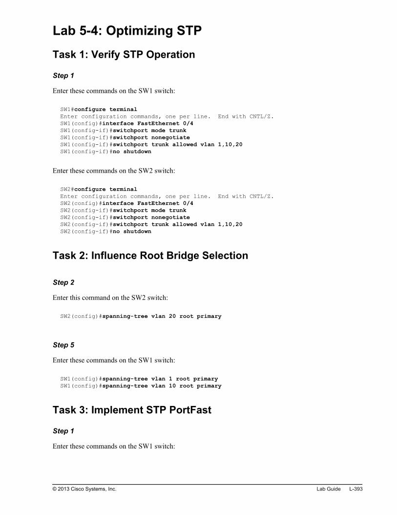
Lab 5-4: Optimizing STP
Task 1: Verify STP Operation
Step 1
Enter these commands on the SW1 switch:
SW1#configure terminal Enter configuration commands, one per line. End with CNTL/Z.SW1(config)#interface FastEthernet 0/4SW1(config-if)#switchport mode trunkSW1(config-if)#switchport nonegotiateSW1(config-if)#switchport trunk allowed vlan 1,10,20SW1(config-if)#no shutdown
Enter these commands on the SW2 switch:
SW2#configure terminal Enter configuration commands, one per line. End with CNTL/Z.SW2(config)#interface FastEthernet 0/4SW2(config-if)#switchport mode trunkSW2(config-if)#switchport nonegotiateSW2(config-if)#switchport trunk allowed vlan 1,10,20SW2(config-if)#no shutdown
Task 2: Influence Root Bridge Selection
Step 2
Enter this command on the SW2 switch:
SW2(config)#spanning-tree vlan 20 root primary
Step 5
Enter these commands on the SW1 switch:
SW1(config)#spanning-tree vlan 1 root primarySW1(config)#spanning-tree vlan 10 root primary
Task 3: Implement STP PortFast
Step 1
Enter these commands on the SW1 switch:
© 2013 Cisco Systems, Inc. Lab Guide L-393

SW1(config)#interface FastEthernet 0/1SW1(config-if)#shutdown
Step 3
Enter these commands on the SW1 switch:
SW1(config)#interface FastEthernet 0/1SW1(config-if)#no shutdown
Step 4
Enter these commands on the SW1 switch:
SW1(config)#interface FastEthernet 0/1SW1(config-if)#spanning-tree portfast
Step 5
Enter these commands on the SW1 switch:
SW1(config)#interface FastEthernet 0/1SW1(config-if)#shutdownSW1(config-if)#no shutdown
Task 4: Implement STP BPDU Guard
Step 2
Enter these commands on the SW1 switch:
SW1(config)#interface FastEthernet 0/3SW1(config-if)#spanning-tree bpduguard enable
Step 4
Enter these commands on the SW1 switch:
SW1(config)#interface FastEthernet 0/3SW1(config)#no spanning-tree bpduguard enableSW1(config)#shutdownSW1(config)#no shutdown
L-394 Interconnecting Cisco Networking Devices: Accelerated © 2013 Cisco Systems, Inc.
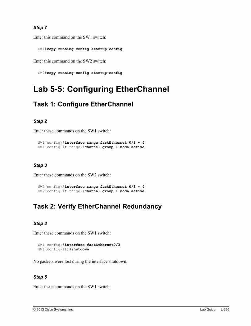
Step 7
Enter this command on the SW1 switch:
SW1#copy running-config startup-config
Enter this command on the SW2 switch:
SW2#copy running-config startup-config
Lab 5-5: Configuring EtherChannel
Task 1: Configure EtherChannel
Step 2
Enter these commands on the SW1 switch:
SW1(config)#interface range fastEthernet 0/3 - 4SW1(config-if-range)#channel-group 1 mode active
Step 3
Enter these commands on the SW2 switch:
SW2(config)#interface range fastEthernet 0/3 - 4SW2(config-if-range)#channel-group 1 mode active
Task 2: Verify EtherChannel Redundancy
Step 3
Enter these commands on the SW1 switch:
SW1(config)#interface fastEthernet0/3SW1(config-if)#shutdown
No packets were lost during the interface shutdown.
Step 5
Enter these commands on the SW1 switch:
© 2013 Cisco Systems, Inc. Lab Guide L-395

SW1(config)#interface fastEthernet0/3SW1(config-if)#no shutdown
Step 8
Enter this command on the SW1 switch:
SW1#copy running-config startup-config
Enter this command on the SW2 switch:
SW2#copy running-config startup-config
Lab 6-1: Troubleshooting IP Connectivity
Task 1: Troubleshoot the Default Route
Step 5
Enter this command on the Branch router:
Branch(config)#ip route 0.0.0.0 0.0.0.0 209.165.201.2
Task 2: Troubleshoot an ACL
Step 5
Enter these commands on the Branch router:
Branch(config)#ip access-list extended Outbound-ACLBranch(config-ext-nacl)#permit tcp any any eq Telnet Branch(config-ext-nacl)#permit tcp any any eq www
Step 7
To see a successful response from the traceroute command on SW1, allow UDP on the Branch router. Thetraceroute command is sending UDP packets with different TTL values. As a response to the original UDPpacket, the ICMP packet is sent.Because it was said that only HTTP and Telnet traffic should be allowed, access list permitting tracerouteis not needed at this point.
Task 3: Troubleshoot the Default Gateway and NameResolution Settings
L-396 Interconnecting Cisco Networking Devices: Accelerated © 2013 Cisco Systems, Inc.

Step 7
Enter this command on the Branch router.
Branch#copy running-config startup-config
Lab 7-1: Configuring and Troubleshooting a SerialConnection
Task 1: Troubleshoot PPP
Step 5
Enter these commands on the Branch router:
Branch(config)#interface Serial 0/0/0Branch(config-if)#ppp authentication chap
Step 6
Enter this command on the Branch router:
Branch# debug ppp authentication
Step 9
On the Branch router, configure this command:
Branch(config)#username HQ password cisco
Task 2: Enable HDLC Encapsulation
Step 2
Enter these commands on the HQ router:
HQ#configure terminal Enter configuration commands, one per line. End with CNTL/Z.HQ(config)#interface Serial 0/0/0HQ(config-if)#encapsulation hdlc
© 2013 Cisco Systems, Inc. Lab Guide L-397

Step 4
Enter these commands on the Branch router:
Branch(config)#interface Serial 0/0/0Branch(config-if)#encapsulation hdlc
Step 5
Enter this sequence of commands:
Branch#copy running-config startup-configDestination filename [startup-config]?Building configuration...[OK]Branch#telnet 192.168.1.2Trying 192.168.1.2 ... OpenHQ#copy running-config startup-configDestination filename [startup-config]?Building configuration...[OK]
Lab 7-2: Establishing a Frame Relay WAN
Task 1: Configure and Verify Basic Frame Relay
Step 2
Enter these commands on the Branch router:
Branch#configure terminalBranch(config)#interface GigabitEthernet 0/1Branch(config-if)#no shutdown
Step 6
Enter the following commands on the Branch router:
Branch#configure terminal Branch(config)#interface Serial0/0/0Branch(config-if)#encapsulation frame-relay
Step 3
The local DLCI number is 120.
L-398 Interconnecting Cisco Networking Devices: Accelerated © 2013 Cisco Systems, Inc.

Step 4
DLCI: 120, IP address: 192.168.1.2
Task 2: Configure and Verify Frame Relay Subinterfaces
Step 2
Enter the following commands on the Branch router:
Branch#configure terminal Branch(config)#interface Serial0/0/0Branch(config-if)#no ip address
Step 3
Enter the following commands on the Branch router:
Branch(config)#interface Serial0/0/0.120 point-to-point Branch(config-subif)#ip address 192.168.1.1 255.255.255.0
Step 4
On point-to-point subinterfaces, it is always assumed that the end point of the point-to-point connectionautomatically resides on the same subnet as the start point.
Step 5
Enter the following commands on the Branch router:
Branch(config)#interface Serial0/0/0.120 point-to-point Branch(config-subif)#frame-relay interface-dlci 120
Task 3: Remove Frame Relay Configuration
Step 2
Enter the following commands on the Branch router:
Branch#configure terminal Branch(config)#no interface Serial0/0/0.120
© 2013 Cisco Systems, Inc. Lab Guide L-399

Step 3
Enter the following commands on the Branch router:
Branch(config)#interface Serial0/0/0Branch(config-if)#encapsulation hdlc
Step 4
Enter the following commands on the Branch router:
Branch(config-if)#ip address 192.168.1.1 255.255.255.0
Step 6
Enter the following commands on the HQ router:
HQ(config)#interface Serial0/0/0HQ(config-if)#encapsulation hdlc
Step 7
Enter these commands:
HQ#copy running-config startup-configHQ#exit[Connection to 209.165.201.2 closed by foreign host]Branch#copy running-config startup-config
Lab 7-3: Establishing a GRE Tunnel
Task 1: Configure and Verify a GRE Tunnel
Step 1
Enter these commands on the Branch router:
Branch(config)#interface Tunnel0Branch(config-if)#tunnel source 209.165.201.1Branch(config-if)#tunnel destination 209.165.201.2Branch(config-if)#ip address 192.168.2.1 255.255.255.0
L-400 Interconnecting Cisco Networking Devices: Accelerated © 2013 Cisco Systems, Inc.

Step 2
Enter these commands:
Branch#telnet 172.16.1.100Trying 172.16.1.100 ... OpenHQ#configure terminalHQ(config)#interface Tunnel0HQ(config-if)#no shutdown
Lab 8-1: Implementing EIGRP
Task 1: Configure and Verify EIGRP
Step 1
Enter this command sequence on the Branch router:
Branch#configure terminalBranch(config)#router eigrp 1Branch(config-router)#
Step 2
Enter this command sequence on the Branch router:
Branch(config-router)#network 10.1.1.0 0.0.0.255Branch(config-router)#network 10.1.10.0 0.0.0.255Branch(config-router)#network 10.1.20.0 0.0.0.255Branch(config-router)#network 192.168.1.0 0.0.0.255
Task 2: Investigate Neighbor Events
Step 1
Enter the following command on the Branch router:
Branch#debug eigrp neighborsEIGRP Static Neighbor debugging is on
Step 2
Enter the following command on the Branch router:
© 2013 Cisco Systems, Inc. Lab Guide L-401

Branch#configure terminalBranch(config)#interface S0/0/0Branch(config-if)#shutdown
Step 3
Enter the following command on the Branch router:
Branch#configure terminalBranch(config)#interface S0/0/0Branch(config-if)#no shutdown
Task 3: Configure and Verify EIGRP over a GRE Tunnel
Step 1
Enter these commands on the Branch router:
Branch(config)#router eigrp 1Branch(config-router)#network 192.168.2.0 0.0.0.255
Step 4
Enter these commands on the Branch router:
Branch(config)#interface Serial 0/0/0Branch(config-if)#shutdown
Step 8
Enter these commands on the Branch router:
Branch(config)#interface Serial 0/0/0Branch(config-if)#no shutdown
Step 10
Enter this sequence of commands on the Branch router:
Branch(config)#router eigrp 1Branch(config-router)#no network 192.168.2.0 0.0.0.255
Step 12
Enter these commands on the Branch router:
L-402 Interconnecting Cisco Networking Devices: Accelerated © 2013 Cisco Systems, Inc.

Branch#telnet 192.168.1.2Trying 192.168.1.2 ... OpenHQ#copy running-config startup-configDestination filename [startup-config]?Building configuration...[OK]HQ#exit[Connection to 192.168.1.2 closed by foreign host]Branch#copy runningBranch#copy running-config startBranch#copy running-config startup-configDestination filename [startup-config]?Building configuration...[OK]Branch#
Lab 8-2: Troubleshooting EIGRP
Task 1: Troubleshoot Basic Connectivity
Step 4
The Serial0/0/0 interface that is connected to the HQ router is not operational because it is administrativelyshut down.
Step 5
Enter the following sequence of commands on the Branch router:
Branch#configure terminalBranch(config)#interface s0/0/0Branch(config-if)#no shutdownBranch(config-if)#
Task 2: Troubleshoot EIGRP Neighbors
Step 1
Some possible causes of routers not being EIGRP neighbors are EIGRP numbers being mismatched, thenetwork on the link between routers is not being advertised, or an interface that is configured as passive.
Step 2
The AS numbers match and both routers are advertising the 192.168.1.0 network that is their WAN link, butthe Branch router has the Serial0/0/0 interface configured as passive, so it is not sending or receivingEIGRP hello packets to the HQ router. Adjacency cannot be established without the hello packets.
© 2013 Cisco Systems, Inc. Lab Guide L-403

Step 3
On the Branch router, enter the following sequence of commands:
Branch#configure terminalEnter configuration commands, one per line. End with CNTL/Z.Branch(config)#router eigrp 1Branch(config-router)#no passive-interface s 0/0/0
Task 3: Troubleshoot Routing Table Issues
Step 1
There might be a routing table issue. It might be that all necessary networks are not being advertised or thatthere is an ACL that is blocking advertisements.
Step 2
The HQ router is advertising the 172.16.1.0/24 network and the Branch router knows about this network.The next step is to investigate whether the Branch router is advertising the network to which PC1 belongs.This is why the ping output states "Request timed out." Branch does know how to get to the 172.16.1.0/24network, but HQ does not know how to get back to PC1.
Step 4
Enter this sequence of commands on the Branch router:
Branch#configure terminalEnter configuration commands, one per line. End with CNTL/Z.Branch(config)#router eigrp 1Branch(config-router)#network 10.1.1.0 0.0.0.255Branch(config-router)#network 10.1.10.0 0.0.0.255Branch(config-router)#network 10.1.20.0 0.0.0.255
Step 6
Enter this command on the Branch router:
Branch#copy running-config startup-config
Lab 8-3: Implementing EIGRP for IPv6
Task 1: Enable IPv6 on the Interfaces
L-404 Interconnecting Cisco Networking Devices: Accelerated © 2013 Cisco Systems, Inc.

Step 1
Enter this command on the Branch router:
Branch(config)#ipv6 unicast-routing
Step 2
Enter these commands on the Branch router:
Branch(config)#interface Serial0/0/0Branch(config-if)#ipv6 address 2001:db8:C0A8:100::1/64Branch(config-if)#exitBranch(config)#interface GigabitEthernet0/0.1Branch(config-subif)#ipv6 address 2001:db8:0a01:100::1/64Branch(config-if)#exitBranch(config)#interface GigabitEthernet0/0.10Branch(config-subif)#ipv6 address 2001:db8:0a01:a00::1/64Branch(config-if)#exitBranch(config)#interface GigabitEthernet0/0.20Branch(config-subif)#ipv6 address 2001:db8:0a01:1400::1/64
Task 2: Enable IPv6 EIGRP
Step 1
Enter this command on the Branch router:
Branch(config)#ipv6 router eigrp 1Branch(config-rtr)#no shutdown
EIGRP for IPv6 has a shutdown feature. The routing process should be in no shutdown mode in order tostart running.
Step 2
Enter this command on the Branch router:
Branch(config)#interface Serial0/0/0Branch(config-if)#ipv6 eigrp 1Branch(config-if)#exitBranch(config)#interface GigabitEthernet0/0.1Branch(config-subif)#ipv6 eigrp 1Branch(config-subif)#exitBranch(config)#interface GigabitEthernet0/0.10Branch(config-subif)#ipv6 eigrp 1Branch(config-subif)#exitBranch(config)#interface GigabitEthernet0/0.20Branch(config-subif)#ipv6 eigrp 1
© 2013 Cisco Systems, Inc. Lab Guide L-405

Lab 9-1: Implementing OSPF
Task 1: Configure OSPF
Step 2
Enter the following commands on the Branch router:
Branch#configure terminalBranch(config)#no router eigrp 1
Step 3
Enter the following commands on the Branch router:
Branch(config)#interface Loopback10Branch(config-if)#ip address 10.100.100.100 255.255.255.255
Step 4
Enter the following command on the Branch router:
Branch(config)#router ospf 1
Step 5
Enter the following command on the Branch router:
Branch(config-router)#network 192.168.1.0 0.0.0.255 area 0
Step 6
Enter this sequence of commands on the Branch router:
Branch(config-router)#network 10.1.1.0 0.0.0.255 area 0Branch(config-router)#network 10.1.10.0 0.0.0.255 area 0Branch(config-router)#network 10.1.20.0 0.0.0.255 area 0
Lab 9-2: Configuring Multiarea OSPF
Task 1: Configure Multiarea OSPF
L-406 Interconnecting Cisco Networking Devices: Accelerated © 2013 Cisco Systems, Inc.

Step 2
Enter the following commands on the Branch router:
Branch(config)#router ospf 1Branch(config-router)#network 10.1.1.0 0.0.0.255 area 1Branch(config-router)#network 10.1.10.0 0.0.0.255 area 1Branch(config-router)#network 10.1.20.0 0.0.0.255 area 1Branch(config-router)#network 10.100.100.100 0.0.0.0 area 1
Task 2: Verify Multiarea OSPF
Step 3
The network is seen as an intra-area route. The Branch router is an ABR, which means that routes fromArea 0 and Area 1 are all seen as intra-area routes.
Step 5
The LAN networks are seen as interarea routes. The HQ router is the backbone router in Area 0, while theLAN networks came from Area 1.
Step 8
Enter this command on the Branch router:
Branch#copy running-config startup-config
Lab 9-3: Troubleshooting Multiarea OSPF
Task 1: Troubleshoot OSPF Neighbor Issues
Step 5
The Serial0/0/0 interface is enabled on the router.
Step 6
OSPF is enabled for Area 0 on the Serial0/0/0 interface.
© 2013 Cisco Systems, Inc. Lab Guide L-407

Step 7
The Serial0/0/0 interface is configured as a passive interface. Adjacencies are not established over passiveinterfaces because hello packets are not sent over passive interfaces.
Step 8
Enter these commands on the Branch router:
Branch# configure terminalBranch(config)# router ospf 1Branch(config-router)# no passive-interface Serial0/0/0
Step 13
Enter these commands on the Headquarters router:
Branch# telnet 192.168.1.2Trying 192.168.1.2 ... OpenHQ# configure terminalHQ(config)# router ospf 1HQ(config-router)# no network 192.168.1.0 0.0.0.255 area 1HQ(config-router)# network 192.168.1.0 0.0.0.255 area 0
Task 2: Troubleshoot OSPF Routing Table Issues
Step 2
The Headquarters router incorrectly advertises the 172.16.1.0/24 network. The router is configured toadvertise the 172.16.2.0/24 network, which is not connected to the Headquarters router.
Step 3
Enter these commands on the Headquarters router:
HQ# configure terminalHQ(config)# router ospf 1HQ(config-router)# no network 172.16.2.0 0.0.0.255 area 0HQ(config-router)# network 172.16.1.0 0.0.0.255 area 0
Step 4
Enter this sequence of commands:
L-408 Interconnecting Cisco Networking Devices: Accelerated © 2013 Cisco Systems, Inc.

HQ# copy running-config startup-configHQ# exit[Connection to 192.168.1.2 closed by foreign host]Branch# copy running-config startup-config
Lab 9-4: Configuring OSPF for IPv6
Task 1: Enable OSPFv3
Step 1
Enter these commands on the Branch router:
Branch(config)#ipv6 router ospf 1Branch(config-rtr)#router-id 2.2.2.2.
Step 2
Enter these commands on the Branch router:
Branch(config)#ipv6 router eigrp 1Branch(config-rtr)#shutdown
Step 4
Enter these commands on the Branch router:
Branch(config)#interface Serial 0/0/0Branch(config-if)#ipv6 ospf 1 area 0Branch(config-if)#exitBranch(config)#interface GigabitEthernet0/0.1Branch(config-subif)#ipv6 ospf 1 area 1Branch(config-if)#exitBranch(config)#interface GigabitEthernet0/0.10Branch(config-subif)#ipv6 ospf 1 area 1Branch(config-if)#exitBranch(config)#interface GigabitEthernet0/0.20Branch(config-subif)#ipv6 ospf 1 area 1Branch(config-if)#exit
Step 5
Enter this command on the Branch router:
Branch#copy run start
© 2013 Cisco Systems, Inc. Lab Guide L-409

Lab 10-1: SNMP and Syslog Basic Configuration
Task 1: Configure Router for SNMP Access
Step 1
Enter this command on the Branch router:
Branch(config)# snmp-server community Cisco RW
Step 2
Enter these commands on the Branch router:
Branch(config)# snmp-server location San JoseBranch(config)# snmp-server contact Joe Summer
Task 2: Configure Router for Syslog
Step 1
Enter this command on the Branch router:
Branch(config)# logging 10.1.10.100
Step 2
Enter this command on the Branch router:
Branch(config)# logging trap debugging
Step 4
Enter these commands on the Branch router:
Branch(config)# interface Serial 0/0/0Branch(config-if)# shutdown
Step 5
Enter these commands on the Branch router:
Branch(config)# interface Serial 0/0/0Branch(config-if)# no shutdown
L-410 Interconnecting Cisco Networking Devices: Accelerated © 2013 Cisco Systems, Inc.

Lab 10-2: Analyzing NetFlow Data
Task 1: Analyze NetFlow Data
Step 1
HTTP is responsible for generating the most traffic in your network.
Step 2
The most bandwidth-consuming conversation is the one between user "hmorisondev" and "rapidshare.com."
Step 3
User "hmorrisondev" is the receiver that consumes the most bandwidth.
Step 4
Web site "rapidshare.com" is the transmitter that consumes the most bandwidth.
Step 5
IP group "External" is responsible for the most traffic on your network.
Lab 10-3: Managing Cisco Devices and Licensing
Task 2: Router Password Recovery
Step 2
Power cycle the Branch router.When the router starts booting, send a break sequence to the console to interrupt the boot procedure.
Branch>System Bootstrap, Version 15.0(1r)M15, RELEASE SOFTWARE (fc1)Technical Support: http://www.cisco.com/techsupportCopyright (c) 2011 by cisco Systems, Inc.Total memory size = 512 MB - On-board = 512 MB, DIMM0 = 0 MBCISCO2901/K9 platform with 524288 Kbytes of main memoryMain memory is configured to 72/-1(On-board/DIMM0) bit mode with ECC enabledReadonly ROMMON initializedprogram load complete, entry point: 0x80803000, size: 0x1b340program load complete, entry point: 0x80803000, size: 0x1b340monitor: command "boot" aborted due to user interruptrommon 1 >
Change the configuration register to the value 0x2142 and reset the router.
© 2013 Cisco Systems, Inc. Lab Guide L-411

rommon 1 > confreg 0x2142You must reset or power cycle for new config to take effectrommon 2 > reset
Observe the Branch router console output. The router will start booting. Cancel the initial configurationdialog.
L-412 Interconnecting Cisco Networking Devices: Accelerated © 2013 Cisco Systems, Inc.

System Bootstrap, Version 15.0(1r)M15, RELEASE SOFTWARE (fc1)Technical Support: http://www.cisco.com/techsupportCopyright (c) 2011 by cisco Systems, Inc.Total memory size = 512 MB - On-board = 512 MB, DIMM0 = 0 MBCISCO2901/K9 platform with 524288 Kbytes of main memoryMain memory is configured to 72/-1(On-board/DIMM0) bit mode with ECC enabledReadonly ROMMON initializedprogram load complete, entry point: 0x80803000, size: 0x1b340program load complete, entry point: 0x80803000, size: 0x1b340IOS Image Load Test___________________Digitally Signed Release Softwareprogram load complete, entry point: 0x81000000, size: 0x5d433c0Self decompressing the image : ################################################################################################################################################################################################################################################################################################################################################################################################################################################################################################################################################################################################ [OK]Smart Init is enabledsmart init is sizing iomem TYPE MEMORY_REQ HWIC Slot 0 0x00200000 Onboard devices & buffer pools 0x0228F000----------------------------------------------- TOTAL: 0x0248F000Rounded IOMEM up to: 40Mb.Using 7 percent iomem. [40Mb/512Mb] Restricted Rights LegendUse, duplication, or disclosure by the Government issubject to restrictions as set forth in subparagraph(c) of the Commercial Computer Software - RestrictedRights clause at FAR sec. 52.227-19 and subparagraph(c) (1) (ii) of the Rights in Technical Data and ComputerSoftware clause at DFARS sec. 252.227-7013. cisco Systems, Inc. 170 West Tasman Drive San Jose, California 95134-1706Cisco IOS Software, C2900 Software (C2900-UNIVERSALK9-M), Version 15.2(4)M1, RELEASE SOFTWARE (fc1)Technical Support: http://www.cisco.com/techsupportCopyright (c) 1986-2012 by Cisco Systems, Inc.Compiled Thu 26-Jul-12 20:54 by prod_rel_teamThis product contains cryptographic features and is subject to UnitedStates and local country laws governing import, export, transfer anduse. Delivery of Cisco cryptographic products does not implythird-party authority to import, export, distribute or use encryption.Importers, exporters, distributors and users are responsible forcompliance with U.S. and local country laws. By using this product youagree to comply with applicable laws and regulations. If you are unableto comply with U.S. and local laws, return this product immediately.A summary of U.S. laws governing Cisco cryptographic products may be found at:http://www.cisco.com/wwl/export/crypto/tool/stqrg.htmlIf you require further assistance please contact us by sending email [email protected] CISCO2901/K9 (revision 1.0) with 483328K/40960K bytes of memory.Processor board ID FCZ1642C5XG2 Gigabit Ethernet interfaces1 Serial(sync/async) interface
© 2013 Cisco Systems, Inc. Lab Guide L-413

1 terminal lineDRAM configuration is 64 bits wide with parity enabled.255K bytes of non-volatile configuration memory.250880K bytes of ATA System CompactFlash 0 (Read/Write) --- System Configuration Dialog ---Would you like to enter the initial configuration dialog? [yes/no]: noPress RETURN to get started!<output omitted>Router>
Enter privileged mode and copy the startup configuration into the running configuration.
Router>enable Router#copy startup-config running-configDestination filename [running-config]? <Enter>1174 bytes copied in 0.116 secs (10121 bytes/sec)Branch#
On the Branch router, set the enable secret password to cisco and save the running configuration into thestartup configuration.
Branch#configure terminal Enter configuration commands, one per line. End with CNTL/Z.Branch(config)#enable secret ciscoBranch(config)#endBranch#*Nov 27 09:31:45.883: %SYS-5-CONFIG_I: Configured from console by consoleBranch#copy running-config startup-configDestination filename [startup-config]? <Enter>Building configuration...[OK]Branch#
On the Branch router, change the configuration register back to the value 0x2102.
Branch#configure terminal Enter configuration commands, one per line. End with CNTL/Z.Branch(config)#config-register 0x2102Branch(config)#
Step 3
Enter these commands on the Branch router:
Branch(config)#interface Serial0/0/0Branch(config-if)#no shutdownBranch(config-if)#exitBranch(config)#interface GigabitEthernet0/0.1Branch(config-subif)#no shutdownBranch(config-subif)#exitBranch(config-subif)#interface GigabitEthernet0/0.10Branch(config-subif)#no shutdownBranch(config-subif)#exitBranch(config-subif)#interface GigabitEthernet0/0.20Branch(config-subif)#no shutdown
L-414 Interconnecting Cisco Networking Devices: Accelerated © 2013 Cisco Systems, Inc.

Task 3: Backing Up a Cisco IOS Image
Step 1
Enter these commands on the Branch router:
Branch#show flash0:-#- --length-- -----date/time------ path1 97794040 Nov 16 2012 19:14:08 +00:00 c2900-universalk9-mz.SPA.152-4.M1.bin2 2814 Nov 16 2012 19:14:20 +00:00 cpconfig-29xx.cfg3 1551184 Nov 16 2012 19:14:28 +00:00 securedesktop-ios-3.1.1.45-k9.pkg4 122880 Nov 16 2012 19:14:34 +00:00 home.tar5 415956 Nov 16 2012 19:14:40 +00:00 sslclient-win-1.1.4.176.pkg6 3000320 Nov 16 2012 19:14:48 +00:00 cpexpress.tar7 1038 Nov 16 2012 19:14:56 +00:00 home.shtml8 290 Nov 23 2012 10:24:04 +00:00 TSHOOT_Troubleshoot_ACLs_Branch.cfg153583616 bytes available (102903808 bytes used)
Step 4
Enter these commands on the Branch router:
Branch#copy flash0: tftp:Source filename []? c2900-universalk9-mz.SPA.152-4.M1.binAddress or name of remote host []? 10.1.10.100Destination filename [c2900-universalk9-mz.SPA.152-4.M1.bin]?<Enter>!!!!!!!!!!!!!!!!!!!!!!!!!!!!!!!!!!!!!!!!!!!!!!!!!!!!!!!!!!!!!!!!!!!!!!!!!!!!!!!!!!!!!!!!!!!!!!!!!!!!!!!!!!!!!!!!!!!!!!!!!!!!!!!!!!!!!!!!!!!!!!!!!!!!!!!!!!!!!!!!!!!!!!!!!!!!!!!!!!!!!!!!!!!!!!!!!!!!!!!!!!!!!!!!!!!!!!!!!!!!!!!!!!!!!!!!!!!!!!!!!!!!!!!!!!!!!!!!!!!!!!!!!!!!!!!!!!!!!!!!!!!!!!!!!!!!!!!!!!!!!!!!!!!!!!!!!!!!!!!!!!!!!!!!!!!!!!!!!!!!!!!!!!!!!!!!!!!!!!!!!!!!!!!!!!!!!!!!!!!!!!!!!97794040 bytes copied in 374.688 secs (261001 bytes/sec)
Task 4: Manage the Configuration File
Step 1
Enter these commands on the Branch router:
Branch#copy running-config tftp:Address or name of remote host []? 10.1.10.100Destination filename [branch-confg]?<Enter>!!2049 bytes copied in 0.384 secs (5336 bytes/sec)
Step 3
Enter these commands on the Branch router:
© 2013 Cisco Systems, Inc. Lab Guide L-415

Branch#copy tftp: running-configAddress or name of remote host []? 10.1.10.100Source filename []? branch-confgDestination filename [running-config]?<Enter>Accessing tftp://10.1.10.100/branch-confg...Loading branch-confg from 10.1.10.100 (via GigabitEthernet0/0.10): ![OK - 2216 bytes]2216 bytes copied in 0.268 secs (8269 bytes/sec)
The configuration that is copied from the TFTP server will not overwrite the running configuration. Instead,the two configuration files will be merged.
Step 5
Enter these commands on the Branch router:
Branch-changedconfiguration#configure terminalBranch-changedconfig(config)#hostname BranchBranch(config)#
Step 6
Enter this command on the Branch router:
Branch#copy running-config startup-config
Task 5: Verify Licensing
Step 1
Enter these commands on the Branch router:
L-416 Interconnecting Cisco Networking Devices: Accelerated © 2013 Cisco Systems, Inc.

Branch#show licenseIndex 1 Feature: ipbasek9 Period left: Life time License Type: Permanent License State: Active, In Use License Count: Non-Counted License Priority: MediumIndex 2 Feature: securityk9 Period left: Not Activated Period Used: 0 minute 0 second License Type: EvalRightToUse License State: Not in Use, EULA not accepted License Count: Non-Counted License Priority: NoneIndex 3 Feature: uck9 Period left: Not Activated Period Used: 0 minute 0 second License Type: EvalRightToUse License State: Not in Use, EULA not accepted License Count: Non-Counted License Priority: NoneIndex 4 Feature: datak9 Period left: Not Activated Period Used: 0 minute 0 second License Type: EvalRightToUse License State: Not in Use, EULA not accepted License Count: Non-Counted License Priority: NoneIndex 5 Feature: gatekeeper Period left: Not Activated Period Used: 0 minute 0 second License Type: EvalRightToUse License State: Not in Use, EULA not accepted License Count: Non-Counted License Priority: None<output omitted>
Only the IPBase technology package is activated, which is done by default. This is a permanent license.
© 2013 Cisco Systems, Inc. Lab Guide L-417

L-418 Interconnecting Cisco Networking Devices: Accelerated © 2013 Cisco Systems, Inc.