Embed Size (px)
Citation preview

Configuration and Management of Networks Configuring BGP with default routing Topology
Instructions Step 1 - Build the topology in the Network simulator.
All contents are Copyright © 1992–2010 Cisco Systems, Inc. All rights reserved. This document is Cisco Public Information. Page 1 of 12
CCNPv6 ROUTE
Chapter 6 Lab 6-1, Configuring BGP with Default Routing
Topology
Objectives
! Configure BGP to exchange routing information with two ISPs.
Background
The International Travel Agency (ITA) relies extensively on the Internet for sales. For this reason, the ITA has
decided to create a multihomed ISP connectivity solution and contracted with two ISPs for Internet
connectivity with fault tolerance. Because the ITA is connecting to two different service providers, you must
configure BGP, which runs between the ITA boundary router and the two ISP routers.
Note: This lab uses Cisco 1841 routers with Cisco IOS Release 12.4(24)T1 and the Advanced IP Services
image c1841-advipservicesk9-mz.124-24.T1.bin. You can use other routers (such as a 2801 or 2811) and

Configuration and Management of Networks
CCNPv6 ROUTE
All contents are Copyright © 1992–2010 Cisco Systems, Inc. All rights reserved. This document is Cisco Public Information. Page 2 of 12
Cisco IOS Software versions if they have comparable capabilities and features. Depending on the router or
switch model and Cisco IOS Software version, the commands available and output produced might vary from
what is shown in this lab.
Required Resources
! 3 routers (Cisco 1841 with Cisco IOS Release 12.4(24)T1 Advanced IP Services or comparable)
! Serial and console cables
Step 1: Prepare the routers for the lab.
Cable the network as shown in the topology diagram. Erase the startup configuration and reload each router
to clear previous configurations.
Step 2: Configure the hostname and interface addresses.
a. Assign the routers hostnames. Using the addressing scheme in the diagram, create the loopback
interfaces and apply IP addresses to these and the serial interfaces on ISP1 (R1), ISP2 (R3), and ITA
(R2). The ISP loopbacks simulate real networks that can be reached through the ISP. The two loopbacks
for the ITA router simulate the connections between the ITA boundary router and their core routers. Set a
clock rate on the DCE serial interfaces.
You can copy and paste the following configurations into your routers to begin.
Router R1 (hostname ISP1)
hostname ISP1
!
interface Lo0
description ISP1 Internet Network
ip address 10.1.1.1 255.255.255.0
!
interface Serial0/0/0
description ISP1 -> ITA
ip address 10.0.0.1 255.255.255.252
clock rate 128000
no shutdown
!
end
Router R2 (hostname ITA)
hostname ITA
!
interface Lo0
description Core router network link 1
ip address 192.168.0.1 255.255.255.0
!
interface Lo1
description Core router network link 2
ip address 192.168.1.1 255.255.255.0
!
interface Serial0/0/0
description ITA -> ISP1
ip address 10.0.0.2 255.255.255.252
no shutdown
interface Serial0/0/1 CCNPv6 ROUTE
All contents are Copyright © 1992–2010 Cisco Systems, Inc. All rights reserved. This document is Cisco Public Information. Page 3 of 12
description ITA -> ISP2
ip address 172.16.0.2 255.255.255.252
clock rate 128000
no shutdown
!
end
Router R3 (hostname ISP2)
hostname ISP2
!
interface Lo0
description ISP2 Internet Network
ip address 172.16.1.1 255.255.255.0
!
interface Serial0/0/1
description ISP2 -> ITA
ip address 172.16.0.1 255.255.255.252
no shutdown
!
end
b. Use ping to test the connectivity between the directly connected routers. Note that router ISP1 cannot
reach router ISP2.
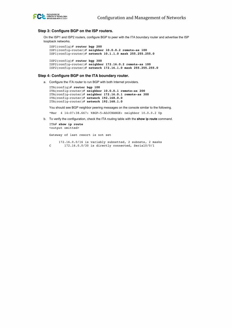
Step 3: Configure BGP on the ISP routers.
On the ISP1 and ISP2 routers, configure BGP to peer with the ITA boundary router and advertise the ISP
loopback networks.
ISP1(config)# router bgp 200
ISP1(config-router)# neighbor 10.0.0.2 remote-as 100
ISP1(config-router)# network 10.1.1.0 mask 255.255.255.0
ISP2(config)# router bgp 300
ISP2(config-router)# neighbor 172.16.0.2 remote-as 100
ISP2(config-router)# network 172.16.1.0 mask 255.255.255.0
Step 4: Configure BGP on the ITA boundary router.
a. Configure the ITA router to run BGP with both Internet providers.
ITA(config)# router bgp 100
ITA(config-router)# neighbor 10.0.0.1 remote-as 200
ITA(config-router)# neighbor 172.16.0.1 remote-as 300
ITA(config-router)# network 192.168.0.0
ITA(config-router)# network 192.168.1.0
You should see BGP neighbor peering messages on the console similar to the following.
*Mar 4 14:07:38.667: %BGP-5-ADJCHANGE: neighbor 10.0.0.2 Up
b. To verify the configuration, check the ITA routing table with the show ip route command.
ITA# show ip route
<output omitted>
Gateway of last resort is not set
172.16.0.0/16 is variably subnetted, 2 subnets, 2 masks
C 172.16.0.0/30 is directly connected, Serial0/0/1
CCNPv6 ROUTE
All contents are Copyright © 1992–2010 Cisco Systems, Inc. All rights reserved. This document is Cisco Public Information. Page 3 of 12
description ITA -> ISP2
ip address 172.16.0.2 255.255.255.252
clock rate 128000
no shutdown
!
end
Router R3 (hostname ISP2)
hostname ISP2
!
interface Lo0
description ISP2 Internet Network
ip address 172.16.1.1 255.255.255.0
!
interface Serial0/0/1
description ISP2 -> ITA
ip address 172.16.0.1 255.255.255.252
no shutdown
!
end
b. Use ping to test the connectivity between the directly connected routers. Note that router ISP1 cannot
reach router ISP2.
Step 3: Configure BGP on the ISP routers.
On the ISP1 and ISP2 routers, configure BGP to peer with the ITA boundary router and advertise the ISP
loopback networks.
ISP1(config)# router bgp 200
ISP1(config-router)# neighbor 10.0.0.2 remote-as 100
ISP1(config-router)# network 10.1.1.0 mask 255.255.255.0
ISP2(config)# router bgp 300
ISP2(config-router)# neighbor 172.16.0.2 remote-as 100
ISP2(config-router)# network 172.16.1.0 mask 255.255.255.0
Step 4: Configure BGP on the ITA boundary router.
a. Configure the ITA router to run BGP with both Internet providers.
ITA(config)# router bgp 100
ITA(config-router)# neighbor 10.0.0.1 remote-as 200
ITA(config-router)# neighbor 172.16.0.1 remote-as 300
ITA(config-router)# network 192.168.0.0
ITA(config-router)# network 192.168.1.0
You should see BGP neighbor peering messages on the console similar to the following.
*Mar 4 14:07:38.667: %BGP-5-ADJCHANGE: neighbor 10.0.0.2 Up
b. To verify the configuration, check the ITA routing table with the show ip route command.
ITA# show ip route
<output omitted>
Gateway of last resort is not set
172.16.0.0/16 is variably subnetted, 2 subnets, 2 masks
C 172.16.0.0/30 is directly connected, Serial0/0/1
Configuration and Management of Networks
CCNPv6 ROUTE
All contents are Copyright © 1992–2010 Cisco Systems, Inc. All rights reserved. This document is Cisco Public Information. Page 3 of 12
description ITA -> ISP2
ip address 172.16.0.2 255.255.255.252
clock rate 128000
no shutdown
!
end
Router R3 (hostname ISP2)
hostname ISP2
!
interface Lo0
description ISP2 Internet Network
ip address 172.16.1.1 255.255.255.0
!
interface Serial0/0/1
description ISP2 -> ITA
ip address 172.16.0.1 255.255.255.252
no shutdown
!
end
b. Use ping to test the connectivity between the directly connected routers. Note that router ISP1 cannot
reach router ISP2.
Step 3: Configure BGP on the ISP routers.
On the ISP1 and ISP2 routers, configure BGP to peer with the ITA boundary router and advertise the ISP
loopback networks.
ISP1(config)# router bgp 200
ISP1(config-router)# neighbor 10.0.0.2 remote-as 100
ISP1(config-router)# network 10.1.1.0 mask 255.255.255.0
ISP2(config)# router bgp 300
ISP2(config-router)# neighbor 172.16.0.2 remote-as 100
ISP2(config-router)# network 172.16.1.0 mask 255.255.255.0
Step 4: Configure BGP on the ITA boundary router.
a. Configure the ITA router to run BGP with both Internet providers.
ITA(config)# router bgp 100
ITA(config-router)# neighbor 10.0.0.1 remote-as 200
ITA(config-router)# neighbor 172.16.0.1 remote-as 300
ITA(config-router)# network 192.168.0.0
ITA(config-router)# network 192.168.1.0
You should see BGP neighbor peering messages on the console similar to the following.
*Mar 4 14:07:38.667: %BGP-5-ADJCHANGE: neighbor 10.0.0.2 Up
b. To verify the configuration, check the ITA routing table with the show ip route command.
ITA# show ip route
<output omitted>
Gateway of last resort is not set
172.16.0.0/16 is variably subnetted, 2 subnets, 2 masks
C 172.16.0.0/30 is directly connected, Serial0/0/1

Configuration and Management of Networks
CCNPv6 ROUTE
All contents are Copyright © 1992–2010 Cisco Systems, Inc. All rights reserved. This document is Cisco Public Information. Page 4 of 12
B 172.16.1.0/24 [20/0] via 172.16.0.1, 00:00:32
10.0.0.0/8 is variably subnetted, 2 subnets, 2 masks
B 10.1.1.0/24 [20/0] via 10.0.0.1, 00:00:31
C 10.0.0.0/30 is directly connected, Serial0/0/0
C 192.168.0.0/24 is directly connected, Loopback0
C 192.168.1.0/24 is directly connected, Loopback1
ITA has routes to the loopback networks at each ISP router.
c. Run the following Tcl script on all routers to verify connectivity If these pings are not successful,
troubleshoot.
Note: The WAN subnets connecting ITA (R2) to the ISPs (R1 and R3) are not advertised in BGP, so the
ISPs will not be able to ping each other’s serial interface address.
ITA# tclsh
foreach address {
10.0.0.1
10.0.0.2
10.1.1.1
172.16.0.1
172.16.0.2
172.16.1.1
192.168.0.1
192.168.1.1
} {
ping $address }
Step 5: Verify BGP on the routers.
a. To verify the BGP operation on ITA, issue the show ip bgp command.
ITA# show ip bgp
BGP table version is 5, local router ID is 192.168.1.1
Status codes: s suppressed, d damped, h history, * valid, > best, i -
internal
Origin codes: i - IGP, e - EGP, ? - incomplete
Network Next Hop Metric LocPrf Weight Path
*> 10.1.1.0/24 10.0.0.1 0 0 200 i
*> 172.16.1.0/24 172.16.0.1 0 0 300 i
*> 192.168.0.0 0.0.0.0 0 32768 i
*> 192.168.1.0 0.0.0.0 0 32768 i
What is the local router ID?
_______________________________________________________________________________
Which table version is displayed?
_______________________________________________________________________________
An asterisk (*) next to a route indicates that it is valid. An angle bracket (>) indicates that the route has
been selected as the best route.
b. To verify the operation of ISP1, issue the show ip bgp command.
ISP1# show ip bgp
BGP table version is 5, local router ID is 10.1.1.1
Status codes: s suppressed, d damped, h history, * valid, > best, i -
internal,
CCNPv6 ROUTE
All contents are Copyright © 1992–2010 Cisco Systems, Inc. All rights reserved. This document is Cisco Public Information. Page 4 of 12
B 172.16.1.0/24 [20/0] via 172.16.0.1, 00:00:32
10.0.0.0/8 is variably subnetted, 2 subnets, 2 masks
B 10.1.1.0/24 [20/0] via 10.0.0.1, 00:00:31
C 10.0.0.0/30 is directly connected, Serial0/0/0
C 192.168.0.0/24 is directly connected, Loopback0
C 192.168.1.0/24 is directly connected, Loopback1
ITA has routes to the loopback networks at each ISP router.
c. Run the following Tcl script on all routers to verify connectivity If these pings are not successful,
troubleshoot.
Note: The WAN subnets connecting ITA (R2) to the ISPs (R1 and R3) are not advertised in BGP, so the
ISPs will not be able to ping each other’s serial interface address.
ITA# tclsh
foreach address {
10.0.0.1
10.0.0.2
10.1.1.1
172.16.0.1
172.16.0.2
172.16.1.1
192.168.0.1
192.168.1.1
} {
ping $address }
Step 5: Verify BGP on the routers.
a. To verify the BGP operation on ITA, issue the show ip bgp command.
ITA# show ip bgp
BGP table version is 5, local router ID is 192.168.1.1
Status codes: s suppressed, d damped, h history, * valid, > best, i -
internal
Origin codes: i - IGP, e - EGP, ? - incomplete
Network Next Hop Metric LocPrf Weight Path
*> 10.1.1.0/24 10.0.0.1 0 0 200 i
*> 172.16.1.0/24 172.16.0.1 0 0 300 i
*> 192.168.0.0 0.0.0.0 0 32768 i
*> 192.168.1.0 0.0.0.0 0 32768 i
What is the local router ID?
_______________________________________________________________________________
Which table version is displayed?
_______________________________________________________________________________
An asterisk (*) next to a route indicates that it is valid. An angle bracket (>) indicates that the route has
been selected as the best route.
b. To verify the operation of ISP1, issue the show ip bgp command.
ISP1# show ip bgp
BGP table version is 5, local router ID is 10.1.1.1
Status codes: s suppressed, d damped, h history, * valid, > best, i -
internal, CCNPv6 ROUTE
All contents are Copyright © 1992–2010 Cisco Systems, Inc. All rights reserved. This document is Cisco Public Information. Page 5 of 12
r RIB-failure, S Stale
Origin codes: i - IGP, e - EGP, ? - incomplete
Network Next Hop Metric LocPrf Weight Path
*> 10.1.1.0/24 0.0.0.0 0 32768 i
*> 172.16.1.0/24 10.0.0.2 0 100 300 i
*> 192.168.0.0 10.0.0.2 0 0 100 i
*> 192.168.1.0 10.0.0.2 0 0 100 i
From ISP1, what is the path to network 172.16.1.0/24?
_______________________________________________________________________________
c. On the ISP1 router, issue the shutdown command on Loopback0. Then on ITA, issue the show ip bgp
command again.
ITA# show ip bgp
BGP table version is 6, local router ID is 192.168.1.1
Status codes: s suppressed, d damped, h history, * valid, > best, i -
internal,
r RIB-failure, S Stale
Origin codes: i - IGP, e - EGP, ? - incomplete
Network Next Hop Metric LocPrf Weight Path
*> 172.16.1.0/24 172.16.0.1 0 0 300 i
*> 192.168.0.0 0.0.0.0 0 32768 i
*> 192.168.1.0 0.0.0.0 0 32768 i
Which table version is displayed? Why?
_______________________________________________________________________________
_______________________________________________________________________________
What happened to the route for network 10.1.1.0/24?
_______________________________________________________________________________
d. Bring ISP1 router Loopback0 back up by issuing the no shutdown command.
e. On ITA, issue the show ip bgp neighbors command. The following is a partial sample output of the
command showing neighbor 172.16.0.1.
BGP neighbor is 172.16.0.1, remote AS 300, external link
BGP version 4, remote router ID 172.16.1.1
BGP state = Established, up for 00:16:00
Last read 00:00:54, last write 00:00:43, hold time is 180, keepalive
interval
is 60 seconds
Neighbor capabilities:
Route refresh: advertised and received(new)
New ASN Capability: advertised and received
Address family IPv4 Unicast: advertised and received
Message statistics:
InQ depth is 0
OutQ depth is 0
Sent Rcvd
Opens: 1 1
Notifications: 0 0
Updates: 5 1
Keepalives: 15 17
CCNPv6 ROUTE
All contents are Copyright © 1992–2010 Cisco Systems, Inc. All rights reserved. This document is Cisco Public Information. Page 5 of 12
r RIB-failure, S Stale
Origin codes: i - IGP, e - EGP, ? - incomplete
Network Next Hop Metric LocPrf Weight Path
*> 10.1.1.0/24 0.0.0.0 0 32768 i
*> 172.16.1.0/24 10.0.0.2 0 100 300 i
*> 192.168.0.0 10.0.0.2 0 0 100 i
*> 192.168.1.0 10.0.0.2 0 0 100 i
From ISP1, what is the path to network 172.16.1.0/24?
_______________________________________________________________________________
c. On the ISP1 router, issue the shutdown command on Loopback0. Then on ITA, issue the show ip bgp
command again.
ITA# show ip bgp
BGP table version is 6, local router ID is 192.168.1.1
Status codes: s suppressed, d damped, h history, * valid, > best, i -
internal,
r RIB-failure, S Stale
Origin codes: i - IGP, e - EGP, ? - incomplete
Network Next Hop Metric LocPrf Weight Path
*> 172.16.1.0/24 172.16.0.1 0 0 300 i
*> 192.168.0.0 0.0.0.0 0 32768 i
*> 192.168.1.0 0.0.0.0 0 32768 i
Which table version is displayed? Why?
_______________________________________________________________________________
_______________________________________________________________________________
What happened to the route for network 10.1.1.0/24?
_______________________________________________________________________________
d. Bring ISP1 router Loopback0 back up by issuing the no shutdown command.
e. On ITA, issue the show ip bgp neighbors command. The following is a partial sample output of the
command showing neighbor 172.16.0.1.
BGP neighbor is 172.16.0.1, remote AS 300, external link
BGP version 4, remote router ID 172.16.1.1
BGP state = Established, up for 00:16:00
Last read 00:00:54, last write 00:00:43, hold time is 180, keepalive
interval
is 60 seconds
Neighbor capabilities:
Route refresh: advertised and received(new)
New ASN Capability: advertised and received
Address family IPv4 Unicast: advertised and received
Message statistics:
InQ depth is 0
OutQ depth is 0
Sent Rcvd
Opens: 1 1
Notifications: 0 0
Updates: 5 1
Keepalives: 15 17

Configuration and Management of Networks
CCNPv6 ROUTE
All contents are Copyright © 1992–2010 Cisco Systems, Inc. All rights reserved. This document is Cisco Public Information. Page 5 of 12
r RIB-failure, S Stale
Origin codes: i - IGP, e - EGP, ? - incomplete
Network Next Hop Metric LocPrf Weight Path
*> 10.1.1.0/24 0.0.0.0 0 32768 i
*> 172.16.1.0/24 10.0.0.2 0 100 300 i
*> 192.168.0.0 10.0.0.2 0 0 100 i
*> 192.168.1.0 10.0.0.2 0 0 100 i
From ISP1, what is the path to network 172.16.1.0/24?
_______________________________________________________________________________
c. On the ISP1 router, issue the shutdown command on Loopback0. Then on ITA, issue the show ip bgp
command again.
ITA# show ip bgp
BGP table version is 6, local router ID is 192.168.1.1
Status codes: s suppressed, d damped, h history, * valid, > best, i -
internal,
r RIB-failure, S Stale
Origin codes: i - IGP, e - EGP, ? - incomplete
Network Next Hop Metric LocPrf Weight Path
*> 172.16.1.0/24 172.16.0.1 0 0 300 i
*> 192.168.0.0 0.0.0.0 0 32768 i
*> 192.168.1.0 0.0.0.0 0 32768 i
Which table version is displayed? Why?
_______________________________________________________________________________
_______________________________________________________________________________
What happened to the route for network 10.1.1.0/24?
_______________________________________________________________________________
d. Bring ISP1 router Loopback0 back up by issuing the no shutdown command.
e. On ITA, issue the show ip bgp neighbors command. The following is a partial sample output of the
command showing neighbor 172.16.0.1.
BGP neighbor is 172.16.0.1, remote AS 300, external link
BGP version 4, remote router ID 172.16.1.1
BGP state = Established, up for 00:16:00
Last read 00:00:54, last write 00:00:43, hold time is 180, keepalive
interval
is 60 seconds
Neighbor capabilities:
Route refresh: advertised and received(new)
New ASN Capability: advertised and received
Address family IPv4 Unicast: advertised and received
Message statistics:
InQ depth is 0
OutQ depth is 0
Sent Rcvd
Opens: 1 1
Notifications: 0 0
Updates: 5 1
Keepalives: 15 17 CCNPv6 ROUTE
All contents are Copyright © 1992–2010 Cisco Systems, Inc. All rights reserved. This document is Cisco Public Information. Page 6 of 12
Route Refresh: 0 0
Total: 21 19
Default minimum time between advertisement runs is 30 seconds
<output omitted>
Based on the output of this command, what is the BGP state between this router and ISP2?
_______________________________________________________________________________
_______________________________________________________________________________
How long has this connection been up?
_______________________________________________________________________________
Step 6: Configure route filters.
a. Check the ISP2 routing table using the show ip route command. ISP2 should have a route that belongs
to ISP1, network 10.1.1.0.
ISP2# show ip route
<output omitted>
172.16.0.0/16 is variably subnetted, 2 subnets, 2 masks
C 172.16.0.0/30 is directly connected, Serial0/0/1
C 172.16.1.0/24 is directly connected, Loopback0
10.0.0.0/24 is subnetted, 1 subnets
B 10.1.1.0 [20/0] via 172.16.0.2, 00:05:22
B 192.168.0.0/24 [20/0] via 172.16.0.2, 00:17:45
B 192.168.1.0/24 [20/0] via 172.16.0.2, 00:17:45
If ITA advertises a route belonging to ISP1, ISP2 installs that route in its table. ISP2 might then attempt to
route transit traffic through the ITA. Configure the ITA router so that it advertises only ITA networks
192.168.0.0 and 192.168.1.0 to both providers.
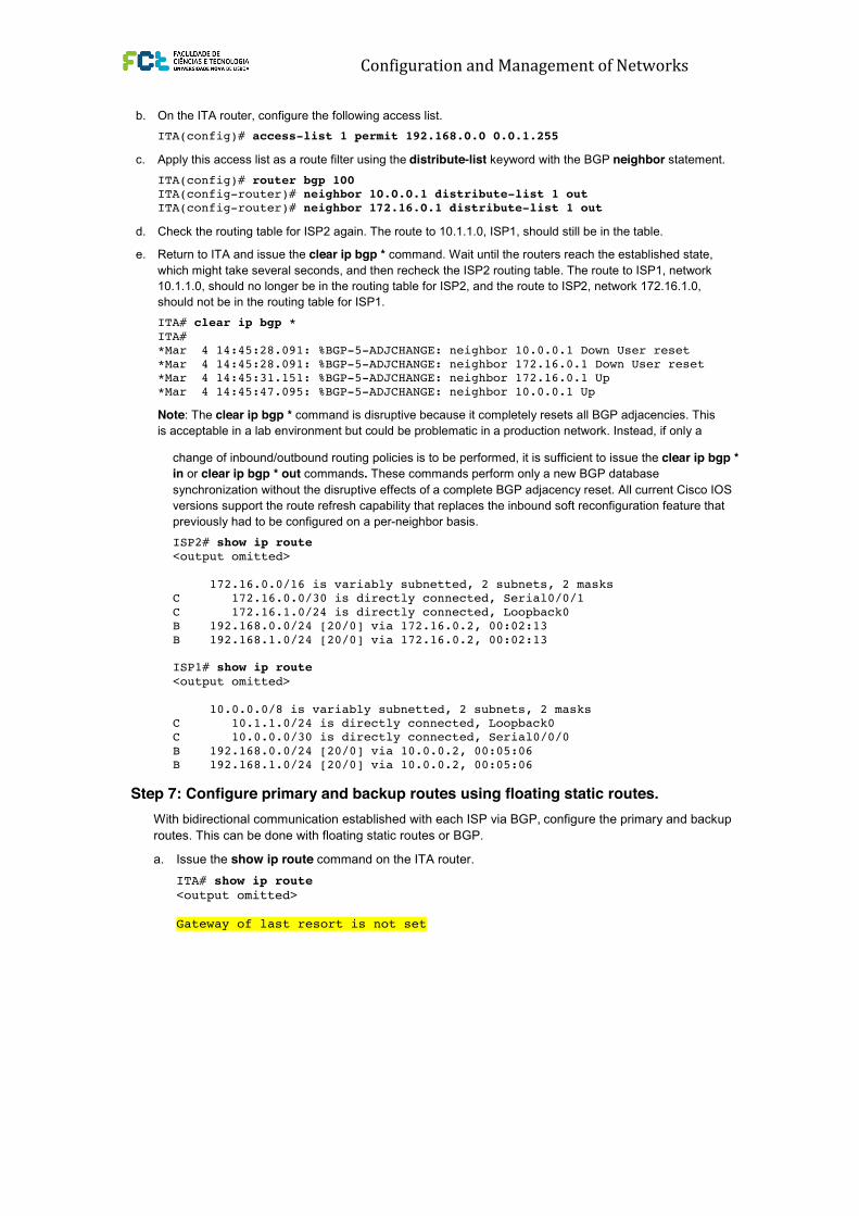
b. On the ITA router, configure the following access list.
ITA(config)# access-list 1 permit 192.168.0.0 0.0.1.255
c. Apply this access list as a route filter using the distribute-list keyword with the BGP neighbor statement.
ITA(config)# router bgp 100
ITA(config-router)# neighbor 10.0.0.1 distribute-list 1 out
ITA(config-router)# neighbor 172.16.0.1 distribute-list 1 out
d. Check the routing table for ISP2 again. The route to 10.1.1.0, ISP1, should still be in the table.
e. Return to ITA and issue the clear ip bgp * command. Wait until the routers reach the established state,
which might take several seconds, and then recheck the ISP2 routing table. The route to ISP1, network
10.1.1.0, should no longer be in the routing table for ISP2, and the route to ISP2, network 172.16.1.0,
should not be in the routing table for ISP1.
ITA# clear ip bgp *
ITA#
*Mar 4 14:45:28.091: %BGP-5-ADJCHANGE: neighbor 10.0.0.1 Down User reset
*Mar 4 14:45:28.091: %BGP-5-ADJCHANGE: neighbor 172.16.0.1 Down User reset
*Mar 4 14:45:31.151: %BGP-5-ADJCHANGE: neighbor 172.16.0.1 Up
*Mar 4 14:45:47.095: %BGP-5-ADJCHANGE: neighbor 10.0.0.1 Up
Note: The clear ip bgp * command is disruptive because it completely resets all BGP adjacencies. This
is acceptable in a lab environment but could be problematic in a production network. Instead, if only a
CCNPv6 ROUTE
All contents are Copyright © 1992–2010 Cisco Systems, Inc. All rights reserved. This document is Cisco Public Information. Page 6 of 12
Route Refresh: 0 0
Total: 21 19
Default minimum time between advertisement runs is 30 seconds
<output omitted>
Based on the output of this command, what is the BGP state between this router and ISP2?
_______________________________________________________________________________
_______________________________________________________________________________
How long has this connection been up?
_______________________________________________________________________________
Step 6: Configure route filters.
a. Check the ISP2 routing table using the show ip route command. ISP2 should have a route that belongs
to ISP1, network 10.1.1.0.
ISP2# show ip route
<output omitted>
172.16.0.0/16 is variably subnetted, 2 subnets, 2 masks
C 172.16.0.0/30 is directly connected, Serial0/0/1
C 172.16.1.0/24 is directly connected, Loopback0
10.0.0.0/24 is subnetted, 1 subnets
B 10.1.1.0 [20/0] via 172.16.0.2, 00:05:22
B 192.168.0.0/24 [20/0] via 172.16.0.2, 00:17:45
B 192.168.1.0/24 [20/0] via 172.16.0.2, 00:17:45
If ITA advertises a route belonging to ISP1, ISP2 installs that route in its table. ISP2 might then attempt to
route transit traffic through the ITA. Configure the ITA router so that it advertises only ITA networks
192.168.0.0 and 192.168.1.0 to both providers.
b. On the ITA router, configure the following access list.
ITA(config)# access-list 1 permit 192.168.0.0 0.0.1.255
c. Apply this access list as a route filter using the distribute-list keyword with the BGP neighbor statement.
ITA(config)# router bgp 100
ITA(config-router)# neighbor 10.0.0.1 distribute-list 1 out
ITA(config-router)# neighbor 172.16.0.1 distribute-list 1 out
d. Check the routing table for ISP2 again. The route to 10.1.1.0, ISP1, should still be in the table.
e. Return to ITA and issue the clear ip bgp * command. Wait until the routers reach the established state,
which might take several seconds, and then recheck the ISP2 routing table. The route to ISP1, network
10.1.1.0, should no longer be in the routing table for ISP2, and the route to ISP2, network 172.16.1.0,
should not be in the routing table for ISP1.
ITA# clear ip bgp *
ITA#
*Mar 4 14:45:28.091: %BGP-5-ADJCHANGE: neighbor 10.0.0.1 Down User reset
*Mar 4 14:45:28.091: %BGP-5-ADJCHANGE: neighbor 172.16.0.1 Down User reset
*Mar 4 14:45:31.151: %BGP-5-ADJCHANGE: neighbor 172.16.0.1 Up
*Mar 4 14:45:47.095: %BGP-5-ADJCHANGE: neighbor 10.0.0.1 Up
Note: The clear ip bgp * command is disruptive because it completely resets all BGP adjacencies. This
is acceptable in a lab environment but could be problematic in a production network. Instead, if only a
Configuration and Management of Networks
CCNPv6 ROUTE
All contents are Copyright © 1992–2010 Cisco Systems, Inc. All rights reserved. This document is Cisco Public Information. Page 6 of 12
Route Refresh: 0 0
Total: 21 19
Default minimum time between advertisement runs is 30 seconds
<output omitted>
Based on the output of this command, what is the BGP state between this router and ISP2?
_______________________________________________________________________________
_______________________________________________________________________________
How long has this connection been up?
_______________________________________________________________________________
Step 6: Configure route filters.
a. Check the ISP2 routing table using the show ip route command. ISP2 should have a route that belongs
to ISP1, network 10.1.1.0.
ISP2# show ip route
<output omitted>
172.16.0.0/16 is variably subnetted, 2 subnets, 2 masks
C 172.16.0.0/30 is directly connected, Serial0/0/1
C 172.16.1.0/24 is directly connected, Loopback0
10.0.0.0/24 is subnetted, 1 subnets
B 10.1.1.0 [20/0] via 172.16.0.2, 00:05:22
B 192.168.0.0/24 [20/0] via 172.16.0.2, 00:17:45
B 192.168.1.0/24 [20/0] via 172.16.0.2, 00:17:45
If ITA advertises a route belonging to ISP1, ISP2 installs that route in its table. ISP2 might then attempt to
route transit traffic through the ITA. Configure the ITA router so that it advertises only ITA networks
192.168.0.0 and 192.168.1.0 to both providers.
b. On the ITA router, configure the following access list.
ITA(config)# access-list 1 permit 192.168.0.0 0.0.1.255
c. Apply this access list as a route filter using the distribute-list keyword with the BGP neighbor statement.
ITA(config)# router bgp 100
ITA(config-router)# neighbor 10.0.0.1 distribute-list 1 out
ITA(config-router)# neighbor 172.16.0.1 distribute-list 1 out
d. Check the routing table for ISP2 again. The route to 10.1.1.0, ISP1, should still be in the table.
e. Return to ITA and issue the clear ip bgp * command. Wait until the routers reach the established state,
which might take several seconds, and then recheck the ISP2 routing table. The route to ISP1, network
10.1.1.0, should no longer be in the routing table for ISP2, and the route to ISP2, network 172.16.1.0,
should not be in the routing table for ISP1.
ITA# clear ip bgp *
ITA#
*Mar 4 14:45:28.091: %BGP-5-ADJCHANGE: neighbor 10.0.0.1 Down User reset
*Mar 4 14:45:28.091: %BGP-5-ADJCHANGE: neighbor 172.16.0.1 Down User reset
*Mar 4 14:45:31.151: %BGP-5-ADJCHANGE: neighbor 172.16.0.1 Up
*Mar 4 14:45:47.095: %BGP-5-ADJCHANGE: neighbor 10.0.0.1 Up
Note: The clear ip bgp * command is disruptive because it completely resets all BGP adjacencies. This
is acceptable in a lab environment but could be problematic in a production network. Instead, if only a CCNPv6 ROUTE
All contents are Copyright © 1992–2010 Cisco Systems, Inc. All rights reserved. This document is Cisco Public Information. Page 7 of 12
change of inbound/outbound routing policies is to be performed, it is sufficient to issue the clear ip bgp *
in or clear ip bgp * out commands. These commands perform only a new BGP database
synchronization without the disruptive effects of a complete BGP adjacency reset. All current Cisco IOS
versions support the route refresh capability that replaces the inbound soft reconfiguration feature that
previously had to be configured on a per-neighbor basis.
ISP2# show ip route
<output omitted>
172.16.0.0/16 is variably subnetted, 2 subnets, 2 masks
C 172.16.0.0/30 is directly connected, Serial0/0/1
C 172.16.1.0/24 is directly connected, Loopback0
B 192.168.0.0/24 [20/0] via 172.16.0.2, 00:02:13
B 192.168.1.0/24 [20/0] via 172.16.0.2, 00:02:13
ISP1# show ip route
<output omitted>
10.0.0.0/8 is variably subnetted, 2 subnets, 2 masks
C 10.1.1.0/24 is directly connected, Loopback0
C 10.0.0.0/30 is directly connected, Serial0/0/0
B 192.168.0.0/24 [20/0] via 10.0.0.2, 00:05:06
B 192.168.1.0/24 [20/0] via 10.0.0.2, 00:05:06
Step 7: Configure primary and backup routes using floating static routes.
With bidirectional communication established with each ISP via BGP, configure the primary and backup
routes. This can be done with floating static routes or BGP.
a. Issue the show ip route command on the ITA router.
ITA# show ip route
<output omitted>
Gateway of last resort is not set
172.16.0.0/16 is variably subnetted, 2 subnets, 2 masks
C 172.16.0.0/30 is directly connected, Serial0/0/1
B 172.16.1.0/24 [20/0] via 172.16.0.1, 00:06:58
10.0.0.0/8 is variably subnetted, 2 subnets, 2 masks
B 10.1.1.0/24 [20/0] via 10.0.0.1, 00:06:58
C 10.0.0.0/30 is directly connected, Serial0/0/0
C 192.168.0.0/24 is directly connected, Loopback0
C 192.168.1.0/24 is directly connected, Loopback1
Notice that there is no gateway of last resort defined. This is a problem because ITA is the border router
for the corporate network.
b. Configure static routes to reflect the policy that ISP1 is the primary provider and that ISP2 acts as the
backup by specifying a lower distance metric for the route to ISP1 (210) as compared to the backup route
to ISP2 (distance metric 220).
ITA(config)# ip route 0.0.0.0 0.0.0.0 10.0.0.1 210
ITA(config)# ip route 0.0.0.0 0.0.0.0 172.16.0.1 220
c. Verify that a default route is defined using the show ip route command.
ITA# show ip route
<output omitted>
CCNPv6 ROUTE
All contents are Copyright © 1992–2010 Cisco Systems, Inc. All rights reserved. This document is Cisco Public Information. Page 7 of 12
change of inbound/outbound routing policies is to be performed, it is sufficient to issue the clear ip bgp *
in or clear ip bgp * out commands. These commands perform only a new BGP database
synchronization without the disruptive effects of a complete BGP adjacency reset. All current Cisco IOS
versions support the route refresh capability that replaces the inbound soft reconfiguration feature that
previously had to be configured on a per-neighbor basis.
ISP2# show ip route
<output omitted>
172.16.0.0/16 is variably subnetted, 2 subnets, 2 masks
C 172.16.0.0/30 is directly connected, Serial0/0/1
C 172.16.1.0/24 is directly connected, Loopback0
B 192.168.0.0/24 [20/0] via 172.16.0.2, 00:02:13
B 192.168.1.0/24 [20/0] via 172.16.0.2, 00:02:13
ISP1# show ip route
<output omitted>
10.0.0.0/8 is variably subnetted, 2 subnets, 2 masks
C 10.1.1.0/24 is directly connected, Loopback0
C 10.0.0.0/30 is directly connected, Serial0/0/0
B 192.168.0.0/24 [20/0] via 10.0.0.2, 00:05:06
B 192.168.1.0/24 [20/0] via 10.0.0.2, 00:05:06
Step 7: Configure primary and backup routes using floating static routes.
With bidirectional communication established with each ISP via BGP, configure the primary and backup
routes. This can be done with floating static routes or BGP.
a. Issue the show ip route command on the ITA router.
ITA# show ip route
<output omitted>
Gateway of last resort is not set
172.16.0.0/16 is variably subnetted, 2 subnets, 2 masks
C 172.16.0.0/30 is directly connected, Serial0/0/1
B 172.16.1.0/24 [20/0] via 172.16.0.1, 00:06:58
10.0.0.0/8 is variably subnetted, 2 subnets, 2 masks
B 10.1.1.0/24 [20/0] via 10.0.0.1, 00:06:58
C 10.0.0.0/30 is directly connected, Serial0/0/0
C 192.168.0.0/24 is directly connected, Loopback0
C 192.168.1.0/24 is directly connected, Loopback1
Notice that there is no gateway of last resort defined. This is a problem because ITA is the border router
for the corporate network.
b. Configure static routes to reflect the policy that ISP1 is the primary provider and that ISP2 acts as the
backup by specifying a lower distance metric for the route to ISP1 (210) as compared to the backup route
to ISP2 (distance metric 220).
ITA(config)# ip route 0.0.0.0 0.0.0.0 10.0.0.1 210
ITA(config)# ip route 0.0.0.0 0.0.0.0 172.16.0.1 220
c. Verify that a default route is defined using the show ip route command.
ITA# show ip route
<output omitted>

Configuration and Management of Networks
CCNPv6 ROUTE
All contents are Copyright © 1992–2010 Cisco Systems, Inc. All rights reserved. This document is Cisco Public Information. Page 7 of 12
change of inbound/outbound routing policies is to be performed, it is sufficient to issue the clear ip bgp *
in or clear ip bgp * out commands. These commands perform only a new BGP database
synchronization without the disruptive effects of a complete BGP adjacency reset. All current Cisco IOS
versions support the route refresh capability that replaces the inbound soft reconfiguration feature that
previously had to be configured on a per-neighbor basis.
ISP2# show ip route
<output omitted>
172.16.0.0/16 is variably subnetted, 2 subnets, 2 masks
C 172.16.0.0/30 is directly connected, Serial0/0/1
C 172.16.1.0/24 is directly connected, Loopback0
B 192.168.0.0/24 [20/0] via 172.16.0.2, 00:02:13
B 192.168.1.0/24 [20/0] via 172.16.0.2, 00:02:13
ISP1# show ip route
<output omitted>
10.0.0.0/8 is variably subnetted, 2 subnets, 2 masks
C 10.1.1.0/24 is directly connected, Loopback0
C 10.0.0.0/30 is directly connected, Serial0/0/0
B 192.168.0.0/24 [20/0] via 10.0.0.2, 00:05:06
B 192.168.1.0/24 [20/0] via 10.0.0.2, 00:05:06
Step 7: Configure primary and backup routes using floating static routes.
With bidirectional communication established with each ISP via BGP, configure the primary and backup
routes. This can be done with floating static routes or BGP.
a. Issue the show ip route command on the ITA router.
ITA# show ip route
<output omitted>
Gateway of last resort is not set
172.16.0.0/16 is variably subnetted, 2 subnets, 2 masks
C 172.16.0.0/30 is directly connected, Serial0/0/1
B 172.16.1.0/24 [20/0] via 172.16.0.1, 00:06:58
10.0.0.0/8 is variably subnetted, 2 subnets, 2 masks
B 10.1.1.0/24 [20/0] via 10.0.0.1, 00:06:58
C 10.0.0.0/30 is directly connected, Serial0/0/0
C 192.168.0.0/24 is directly connected, Loopback0
C 192.168.1.0/24 is directly connected, Loopback1
Notice that there is no gateway of last resort defined. This is a problem because ITA is the border router
for the corporate network.
b. Configure static routes to reflect the policy that ISP1 is the primary provider and that ISP2 acts as the
backup by specifying a lower distance metric for the route to ISP1 (210) as compared to the backup route
to ISP2 (distance metric 220).
ITA(config)# ip route 0.0.0.0 0.0.0.0 10.0.0.1 210
ITA(config)# ip route 0.0.0.0 0.0.0.0 172.16.0.1 220
c. Verify that a default route is defined using the show ip route command.
ITA# show ip route
<output omitted>
CCNPv6 ROUTE
All contents are Copyright © 1992–2010 Cisco Systems, Inc. All rights reserved. This document is Cisco Public Information. Page 8 of 12
Gateway of last resort is 10.0.0.1 to network 0.0.0.0
172.16.0.0/16 is variably subnetted, 2 subnets, 2 masks
C 172.16.0.0/30 is directly connected, Serial0/0/1
B 172.16.1.0/24 [20/0] via 172.16.0.1, 00:11:41
10.0.0.0/8 is variably subnetted, 2 subnets, 2 masks
B 10.1.1.0/24 [20/0] via 10.0.0.1, 00:11:41
C 10.0.0.0/30 is directly connected, Serial0/0/0
C 192.168.0.0/24 is directly connected, Loopback0
C 192.168.1.0/24 is directly connected, Loopback1
S* 0.0.0.0/0 [210/0] via 10.0.0.1
d. Test this default route by creating an unadvertised loopback on the router for ISP1.
ISP1# config t
ISP1(config)# interface loopback 100
ISP1(config-if)# ip address 192.168.100.1 255.255.255.0
e. Issue the show ip route command to ensure that the newly added 192.168.100.0 /24 network does not
appear in the routing table.
ITA# show ip route
<output omitted>
Gateway of last resort is 10.0.0.1 to network 0.0.0.0
172.16.0.0/16 is variably subnetted, 2 subnets, 2 masks
C 172.16.0.0/30 is directly connected, Serial0/0/1
B 172.16.1.0/24 [20/0] via 172.16.0.1, 00:16:24
10.0.0.0/8 is variably subnetted, 2 subnets, 2 masks
B 10.1.1.0/24 [20/0] via 10.0.0.1, 00:01:47
C 10.0.0.0/30 is directly connected, Serial0/0/0
C 192.168.0.0/24 is directly connected, Loopback0
C 192.168.1.0/24 is directly connected, Loopback1
S* 0.0.0.0/0 [210/0] via 10.0.0.1
f. In extended ping mode, ping the ISP1 loopback 1 interface 192.168.100.1 with the source originating
from the ITA loopback 1 interface 192.168.1.1.
ITA# ping
Protocol [ip]: Target IP address: 192.168.100.1
Repeat count [5]:
Datagram size [100]:
Timeout in seconds [2]: Extended commands [n]: y
Source address or interface: 192.168.1.1
Type of service [0]:
Set DF bit in IP header? [no]:
Validate reply data? [no]:
Data pattern [0xABCD]:
Loose, Strict, Record, Timestamp, Verbose[none]:
Sweep range of sizes [n]:
Type escape sequence to abort.
Sending 5, 100-byte ICMP Echos to 192.168.100.1, timeout is 2 seconds:
!!!!!
Success rate is 100 percent (5/5), round-trip min/avg/max = 32/32/36 ms
Note: You can bypass extended ping prompted mode and ping while specifying a source address using
one of these abbreviated commands:

Configuration and Management of Networks
CCNPv6 ROUTE
All contents are Copyright © 1992–2010 Cisco Systems, Inc. All rights reserved. This document is Cisco Public Information. Page 8 of 12
Gateway of last resort is 10.0.0.1 to network 0.0.0.0
172.16.0.0/16 is variably subnetted, 2 subnets, 2 masks
C 172.16.0.0/30 is directly connected, Serial0/0/1
B 172.16.1.0/24 [20/0] via 172.16.0.1, 00:11:41
10.0.0.0/8 is variably subnetted, 2 subnets, 2 masks
B 10.1.1.0/24 [20/0] via 10.0.0.1, 00:11:41
C 10.0.0.0/30 is directly connected, Serial0/0/0
C 192.168.0.0/24 is directly connected, Loopback0
C 192.168.1.0/24 is directly connected, Loopback1
S* 0.0.0.0/0 [210/0] via 10.0.0.1
d. Test this default route by creating an unadvertised loopback on the router for ISP1.
ISP1# config t
ISP1(config)# interface loopback 100
ISP1(config-if)# ip address 192.168.100.1 255.255.255.0
e. Issue the show ip route command to ensure that the newly added 192.168.100.0 /24 network does not
appear in the routing table.
ITA# show ip route
<output omitted>
Gateway of last resort is 10.0.0.1 to network 0.0.0.0
172.16.0.0/16 is variably subnetted, 2 subnets, 2 masks
C 172.16.0.0/30 is directly connected, Serial0/0/1
B 172.16.1.0/24 [20/0] via 172.16.0.1, 00:16:24
10.0.0.0/8 is variably subnetted, 2 subnets, 2 masks
B 10.1.1.0/24 [20/0] via 10.0.0.1, 00:01:47
C 10.0.0.0/30 is directly connected, Serial0/0/0
C 192.168.0.0/24 is directly connected, Loopback0
C 192.168.1.0/24 is directly connected, Loopback1
S* 0.0.0.0/0 [210/0] via 10.0.0.1
f. In extended ping mode, ping the ISP1 loopback 1 interface 192.168.100.1 with the source originating
from the ITA loopback 1 interface 192.168.1.1.
ITA# ping
Protocol [ip]: Target IP address: 192.168.100.1
Repeat count [5]:
Datagram size [100]:
Timeout in seconds [2]: Extended commands [n]: y
Source address or interface: 192.168.1.1
Type of service [0]:
Set DF bit in IP header? [no]:
Validate reply data? [no]:
Data pattern [0xABCD]:
Loose, Strict, Record, Timestamp, Verbose[none]:
Sweep range of sizes [n]:
Type escape sequence to abort.
Sending 5, 100-byte ICMP Echos to 192.168.100.1, timeout is 2 seconds:
!!!!!
Success rate is 100 percent (5/5), round-trip min/avg/max = 32/32/36 ms
Note: You can bypass extended ping prompted mode and ping while specifying a source address using
one of these abbreviated commands: CCNPv6 ROUTE
All contents are Copyright © 1992–2010 Cisco Systems, Inc. All rights reserved. This document is Cisco Public Information. Page 9 of 12
ITA# ping 192.168.100.1 source 192.168.1.1
or
ITA# ping 192.168.100.1 source Lo1
Note: Testing the default route by creating an unadvertised network on ISP1 and pinging it works only
because the default route also points toward ISP1. If the preferred default route pointed toward ISP2, the
ping to that unadvertised network on ISP1 would not succeed. If the link to ISP1 failed, the default route
to ISP2 would become active, but the pings would be successful only if ISP1 and ISP2 have another
working interconnection and appropriate BGP peering between them, which is currently not the case.
Step 8: Configure primary and backup routes using a default network and a static route.
Another method for configuring primary and backup routes is to use the ip default-network command instead
of a 0.0.0.0/0 route.
a. Remove the floating static routes configured in Step 7.
ITA(config)# no ip route 0.0.0.0 0.0.0.0 10.0.0.1 210
ITA(config)# no ip route 0.0.0.0 0.0.0.0 172.16.0.1 220
b. The network that was added in Step 7, 192.168.100.0/24, should now be advertised on the ISP1 router.
You might need to wait a few moments for BGP to advertise the new network.
ISP1(config)# router bgp 200
ISP1(config-router)# network 192.168.100.0
ISP1(config-router)# end
c. Make sure that the classful network 192.168.100.0 /24 appears in the ITA routing table.
ITA# show ip route
<output omitted>
Gateway of last resort is not set
172.16.0.0/16 is variably subnetted, 2 subnets, 2 masks
C 172.16.0.0/30 is directly connected, Serial0/0/1
B 172.16.1.0/24 [20/0] via 172.16.0.1, 00:30:10
10.0.0.0/8 is variably subnetted, 2 subnets, 2 masks
B 10.1.1.0/24 [20/0] via 10.0.0.1, 00:02:33
C 10.0.0.0/30 is directly connected, Serial0/0/0
C 192.168.0.0/24 is directly connected, Loopback0
C 192.168.1.0/24 is directly connected, Loopback1 B 192.168.100.0/24 [20/0] via 10.0.0.1, 00:02:33
d. On the ITA router, configure the ip default-network statement to reestablish a gateway of last resort.
ITA(config)# ip default-network 192.168.100.0
Note: The behavior of this command is oriented toward legacy classful protocols and should be used only
with classful networks.
e. Wait a few moments and then reexamine the routing table on ITA.
ITA# show ip route
<output omitted>
Gateway of last resort is 10.0.0.1 to network 192.168.100.0
172.16.0.0/16 is variably subnetted, 2 subnets, 2 masks
C 172.16.0.0/30 is directly connected, Serial0/0/1
CCNPv6 ROUTE
All contents are Copyright © 1992–2010 Cisco Systems, Inc. All rights reserved. This document is Cisco Public Information. Page 9 of 12
ITA# ping 192.168.100.1 source 192.168.1.1
or
ITA# ping 192.168.100.1 source Lo1
Note: Testing the default route by creating an unadvertised network on ISP1 and pinging it works only
because the default route also points toward ISP1. If the preferred default route pointed toward ISP2, the
ping to that unadvertised network on ISP1 would not succeed. If the link to ISP1 failed, the default route
to ISP2 would become active, but the pings would be successful only if ISP1 and ISP2 have another
working interconnection and appropriate BGP peering between them, which is currently not the case.
Step 8: Configure primary and backup routes using a default network and a static route.
Another method for configuring primary and backup routes is to use the ip default-network command instead
of a 0.0.0.0/0 route.
a. Remove the floating static routes configured in Step 7.
ITA(config)# no ip route 0.0.0.0 0.0.0.0 10.0.0.1 210
ITA(config)# no ip route 0.0.0.0 0.0.0.0 172.16.0.1 220
b. The network that was added in Step 7, 192.168.100.0/24, should now be advertised on the ISP1 router.
You might need to wait a few moments for BGP to advertise the new network.
ISP1(config)# router bgp 200
ISP1(config-router)# network 192.168.100.0
ISP1(config-router)# end
c. Make sure that the classful network 192.168.100.0 /24 appears in the ITA routing table.
ITA# show ip route
<output omitted>
Gateway of last resort is not set
172.16.0.0/16 is variably subnetted, 2 subnets, 2 masks
C 172.16.0.0/30 is directly connected, Serial0/0/1
B 172.16.1.0/24 [20/0] via 172.16.0.1, 00:30:10
10.0.0.0/8 is variably subnetted, 2 subnets, 2 masks
B 10.1.1.0/24 [20/0] via 10.0.0.1, 00:02:33
C 10.0.0.0/30 is directly connected, Serial0/0/0
C 192.168.0.0/24 is directly connected, Loopback0
C 192.168.1.0/24 is directly connected, Loopback1 B 192.168.100.0/24 [20/0] via 10.0.0.1, 00:02:33
d. On the ITA router, configure the ip default-network statement to reestablish a gateway of last resort.
ITA(config)# ip default-network 192.168.100.0
Note: The behavior of this command is oriented toward legacy classful protocols and should be used only
with classful networks.
e. Wait a few moments and then reexamine the routing table on ITA.
ITA# show ip route
<output omitted>
Gateway of last resort is 10.0.0.1 to network 192.168.100.0
172.16.0.0/16 is variably subnetted, 2 subnets, 2 masks
C 172.16.0.0/30 is directly connected, Serial0/0/1

Configuration and Management of Networks
CCNPv6 ROUTE
All contents are Copyright © 1992–2010 Cisco Systems, Inc. All rights reserved. This document is Cisco Public Information. Page 9 of 12
ITA# ping 192.168.100.1 source 192.168.1.1
or
ITA# ping 192.168.100.1 source Lo1
Note: Testing the default route by creating an unadvertised network on ISP1 and pinging it works only
because the default route also points toward ISP1. If the preferred default route pointed toward ISP2, the
ping to that unadvertised network on ISP1 would not succeed. If the link to ISP1 failed, the default route
to ISP2 would become active, but the pings would be successful only if ISP1 and ISP2 have another
working interconnection and appropriate BGP peering between them, which is currently not the case.
Step 8: Configure primary and backup routes using a default network and a static route.
Another method for configuring primary and backup routes is to use the ip default-network command instead
of a 0.0.0.0/0 route.
a. Remove the floating static routes configured in Step 7.
ITA(config)# no ip route 0.0.0.0 0.0.0.0 10.0.0.1 210
ITA(config)# no ip route 0.0.0.0 0.0.0.0 172.16.0.1 220
b. The network that was added in Step 7, 192.168.100.0/24, should now be advertised on the ISP1 router.
You might need to wait a few moments for BGP to advertise the new network.
ISP1(config)# router bgp 200
ISP1(config-router)# network 192.168.100.0
ISP1(config-router)# end
c. Make sure that the classful network 192.168.100.0 /24 appears in the ITA routing table.
ITA# show ip route
<output omitted>
Gateway of last resort is not set
172.16.0.0/16 is variably subnetted, 2 subnets, 2 masks
C 172.16.0.0/30 is directly connected, Serial0/0/1
B 172.16.1.0/24 [20/0] via 172.16.0.1, 00:30:10
10.0.0.0/8 is variably subnetted, 2 subnets, 2 masks
B 10.1.1.0/24 [20/0] via 10.0.0.1, 00:02:33
C 10.0.0.0/30 is directly connected, Serial0/0/0
C 192.168.0.0/24 is directly connected, Loopback0
C 192.168.1.0/24 is directly connected, Loopback1 B 192.168.100.0/24 [20/0] via 10.0.0.1, 00:02:33
d. On the ITA router, configure the ip default-network statement to reestablish a gateway of last resort.
ITA(config)# ip default-network 192.168.100.0
Note: The behavior of this command is oriented toward legacy classful protocols and should be used only
with classful networks.
e. Wait a few moments and then reexamine the routing table on ITA.
ITA# show ip route
<output omitted>
Gateway of last resort is 10.0.0.1 to network 192.168.100.0
172.16.0.0/16 is variably subnetted, 2 subnets, 2 masks
C 172.16.0.0/30 is directly connected, Serial0/0/1 CCNPv6 ROUTE
All contents are Copyright © 1992–2010 Cisco Systems, Inc. All rights reserved. This document is Cisco Public Information. Page 10 of 12
B 172.16.1.0/24 [20/0] via 172.16.0.1, 00:32:55
10.0.0.0/8 is variably subnetted, 2 subnets, 2 masks
B 10.1.1.0/24 [20/0] via 10.0.0.1, 00:05:19
C 10.0.0.0/30 is directly connected, Serial0/0/0
C 192.168.0.0/24 is directly connected, Loopback0
C 192.168.1.0/24 is directly connected, Loopback1
B* 192.168.100.0/24 [20/0] via 10.0.0.1, 00:05:19
This establishes ISP1 as the only default route.
f. Make ISP2 the backup ISP by adding a backup route on ITA to ISP2 serial 0/0/1 interface 172.16.0.1.
ITA(config)# ip route 0.0.0.0 0.0.0.0 172.16.0.1 220
EBGP learned routes have an administrative distance of 20 and are preferred over any routes with an
administrative distance greater than 20, such as the default route defined above with an administrative
distance of 220. The default route acts as a backup if the 192.168.100.0 /24 network is unavailable
because of a fault or misconfiguration, or during the short period after a clear ip bgp 10.0.0.1 command
is issued.
g. Verify that this newly added route establishes a consistent default route while the BGP conversation
between ITA and ISP1 reestablishes. Notice that the routing table includes two candidate default routes
(*), only one of which is used because of different administrative distances.
ITA# show ip route
<output omitted>
Gateway of last resort is 10.0.0.1 to network 192.168.100.0
172.16.0.0/16 is variably subnetted, 2 subnets, 2 masks
C 172.16.0.0/30 is directly connected, Serial0/0/1
B 172.16.1.0/24 [20/0] via 172.16.0.1, 00:35:42
10.0.0.0/8 is variably subnetted, 2 subnets, 2 masks
B 10.1.1.0/24 [20/0] via 10.0.0.1, 00:08:05
C 10.0.0.0/30 is directly connected, Serial0/0/0
C 192.168.0.0/24 is directly connected, Loopback0
C 192.168.1.0/24 is directly connected, Loopback1
B* 192.168.100.0/24 [20/0] via 10.0.0.1, 00:08:05
S* 0.0.0.0/0 [220/0] via 172.16.0.1
ITA# clear ip bgp 10.0.0.1
ITA# show ip route
<output omitted>
Gateway of last resort is 172.16.0.1 to network 0.0.0.0
172.16.0.0/16 is variably subnetted, 2 subnets, 2 masks
C 172.16.0.0/30 is directly connected, Serial0/0/1
B 172.16.1.0/24 [20/0] via 172.16.0.1, 00:36:46
10.0.0.0/8 is variably subnetted, 2 subnets, 2 masks
B 10.1.1.0/24 [20/0] via 10.0.0.1, 00:00:00
C 10.0.0.0/30 is directly connected, Serial0/0/0
C 192.168.0.0/24 is directly connected, Loopback0
C 192.168.1.0/24 is directly connected, Loopback1
B 192.168.100.0/24 [20/0] via 10.0.0.1, 00:00:00
S* 0.0.0.0/0 [220/0] via 172.16.0.1
ITA# show ip route
<output omitted>
CCNPv6 ROUTE
All contents are Copyright © 1992–2010 Cisco Systems, Inc. All rights reserved. This document is Cisco Public Information. Page 10 of 12
B 172.16.1.0/24 [20/0] via 172.16.0.1, 00:32:55
10.0.0.0/8 is variably subnetted, 2 subnets, 2 masks
B 10.1.1.0/24 [20/0] via 10.0.0.1, 00:05:19
C 10.0.0.0/30 is directly connected, Serial0/0/0
C 192.168.0.0/24 is directly connected, Loopback0
C 192.168.1.0/24 is directly connected, Loopback1
B* 192.168.100.0/24 [20/0] via 10.0.0.1, 00:05:19
This establishes ISP1 as the only default route.
f. Make ISP2 the backup ISP by adding a backup route on ITA to ISP2 serial 0/0/1 interface 172.16.0.1.
ITA(config)# ip route 0.0.0.0 0.0.0.0 172.16.0.1 220
EBGP learned routes have an administrative distance of 20 and are preferred over any routes with an
administrative distance greater than 20, such as the default route defined above with an administrative
distance of 220. The default route acts as a backup if the 192.168.100.0 /24 network is unavailable
because of a fault or misconfiguration, or during the short period after a clear ip bgp 10.0.0.1 command
is issued.
g. Verify that this newly added route establishes a consistent default route while the BGP conversation
between ITA and ISP1 reestablishes. Notice that the routing table includes two candidate default routes
(*), only one of which is used because of different administrative distances.
ITA# show ip route
<output omitted>
Gateway of last resort is 10.0.0.1 to network 192.168.100.0
172.16.0.0/16 is variably subnetted, 2 subnets, 2 masks
C 172.16.0.0/30 is directly connected, Serial0/0/1
B 172.16.1.0/24 [20/0] via 172.16.0.1, 00:35:42
10.0.0.0/8 is variably subnetted, 2 subnets, 2 masks
B 10.1.1.0/24 [20/0] via 10.0.0.1, 00:08:05
C 10.0.0.0/30 is directly connected, Serial0/0/0
C 192.168.0.0/24 is directly connected, Loopback0
C 192.168.1.0/24 is directly connected, Loopback1
B* 192.168.100.0/24 [20/0] via 10.0.0.1, 00:08:05
S* 0.0.0.0/0 [220/0] via 172.16.0.1
ITA# clear ip bgp 10.0.0.1
ITA# show ip route
<output omitted>
Gateway of last resort is 172.16.0.1 to network 0.0.0.0
172.16.0.0/16 is variably subnetted, 2 subnets, 2 masks
C 172.16.0.0/30 is directly connected, Serial0/0/1
B 172.16.1.0/24 [20/0] via 172.16.0.1, 00:36:46
10.0.0.0/8 is variably subnetted, 2 subnets, 2 masks
B 10.1.1.0/24 [20/0] via 10.0.0.1, 00:00:00
C 10.0.0.0/30 is directly connected, Serial0/0/0
C 192.168.0.0/24 is directly connected, Loopback0
C 192.168.1.0/24 is directly connected, Loopback1
B 192.168.100.0/24 [20/0] via 10.0.0.1, 00:00:00
S* 0.0.0.0/0 [220/0] via 172.16.0.1
ITA# show ip route
<output omitted>

Configuration and Management of Networks
CCNPv6 ROUTE
All contents are Copyright © 1992–2010 Cisco Systems, Inc. All rights reserved. This document is Cisco Public Information. Page 11 of 12
Gateway of last resort is 10.0.0.1 to network 192.168.100.0
172.16.0.0/16 is variably subnetted, 2 subnets, 2 masks
C 172.16.0.0/30 is directly connected, Serial0/0/1
B 172.16.1.0/24 [20/0] via 172.16.0.1, 00:38:05
10.0.0.0/8 is variably subnetted, 2 subnets, 2 masks
B 10.1.1.0/24 [20/0] via 10.0.0.1, 00:01:19
C 10.0.0.0/30 is directly connected, Serial0/0/0
C 192.168.0.0/24 is directly connected, Loopback0
C 192.168.1.0/24 is directly connected, Loopback1
B* 192.168.100.0/24 [20/0] via 10.0.0.1, 00:01:19
S* 0.0.0.0/0 [220/0] via 172.16.0.1
As expected, while the BGP conversation was down between ITA and ISP1, the route to ISP2 was added
as the gateway of last resort. However, when BGP reestablished the conversation between ITA and ISP1,
the default route of 192.168.100.0 was again set as the gateway of last resort on ITA.
h. Run the following Tcl script on router ITA to verify connectivity.
ITA# tclsh
foreach address {
10.0.0.1
10.0.0.2
10.1.1.1
172.16.0.1
172.16.0.2
172.16.1.1
192.168.0.1
192.168.1.1
192.168.100.1
} {
ping $address }
Should ISP1 and ISP2 be able to ping all networks in the topology?
_______________________________________________________________________________
_______________________________________________________________________________
_______________________________________________________________________________
_______________________________________________________________________________
_______________________________________________________________________________
Note: Another option for setting up default routing is to inject a default route via BGP. The following
example configures the ISP1 router to inject a default route to itself that can be used by the ITA router:
ISP1(config)# router bgp 200
ISP1(config-router)# neighbor 10.0.0.2 default-originate