Embed Size (px)
Citation preview

03 April 2013
1
La inclusion del HRF como material con fines estructurales en el nuevo Codigo Modelo 2010
Group Concrete Structures
Seminario sobre experienceas internationales del Hormigon Reforzado con Fibras

03 April 2013 2
Do we really need codes?
...Meeting TG 8.6 Marseille 2012

03 April 2013 3
FRC and UHPFRC: one family or irreconcilable groups?
C20 C80 C180 C200
fib TG 8.3 FRC fib TG 8.6 UHPFRC
03 April 2013 4
Softening versus hardening behaviour in axial tension
Softening hardening

03 April 2013 5
Softening versus hardening: hard to define
Different response of structures made of FRC having a softening or hardening behaviour under uniaxial tension or bending

03 April 2013 6
New Model Code for Concrete Structures
Multi-level design strategy

03 April 2013 7
Test for determing FRC properties in tension

03 April 2013 8
Test for determing FRC properties in tension
2,2
3
sp
j
jRbh
lFf

03 April 2013 9
Definition of strength intervals
The strength interval is defined by two subsequent numbers in the series: 1,0 1,5 2,0 3,0 4,0 5,0 6,0 7,0 8,0 ….. [Mpa]
wherease the letters a, b, c, d, e correspond to the residual strength ratios: a if 0,5 fR3k/fR1k 0,7 b if 0,7 fR3k/fR1k 0,9 c if 0,9 fR3k/fR1k 1,1 d if 1,1 fR3k/fR1k 1,3 e if 1,3 fR3k/fR1k 1,5 Example: a fibre concrete denoted with “3b” has a strength between 3 and 4 Mpa and a fR3k/fR1k ratio ranging between 0,7 and 0,9

03 April 2013 10
Constitutive design laws (Level I)
3
3RFtu
ff
Rigid plastic model:
Linear model:
145,0 RFts ff
0)2,05,0( 13
3
RRFtsu
FtsFtu fffCMOD
wff

03 April 2013 11
Design of FRC members: design in shear
cpck
ctk
Ftukl
c
fRd ff
fkv 15.0)5.71100
18.03/1
,

03 April 2013 12
Constitutive design laws (Level I)
K-values added for different situations For isotropic fibre orientation K = 1,0

03 April 2013 13
The “K-factor” versus “Design by Testing”
0.0
0.5
1.0
1.5
2.0
2.5
0 4 8 12 16 20
Mid-span deflection [mm]
Be
nd
ing
mo
me
nt [k
Nm
]
X Y
Casting in Y-direction

03 April 2013 14
Taking advantage of fibre orientation
Production of precast elements for Haneda airport platform: determining the
most favourable casting method in combination with design by testing

03 April 2013 15
K-factor: relevance of casting method
Unforeseen sliding surface in UHPFRC prestressed beam

03 April 2013 16
Model Code for Concrete Structures
Concrete’s Design for structural safety Design for serviceability Design for durability Design for sustainability
- Constitutive relations for wide range of concrete’s
- Fibres as a reinforcing material - Service life design - Reliable NLFEM analysis - Maintenance as a design issue - Conceptual design

03 April 2013 17
Model Code for Concrete Structures
Concrete’s Design for structural safety Design for serviceability Design for durability Design for sustainability

03 April 2013 18
Introduction of “time” in a structural design code
Recording
Specification of conservation strategy
Determination of tactic and regime for condition control
Revision of conservation strategy and tactic
Final adoption of inspection regime
Start of through life condition monitoring
Condition survey
Condition assessment
Execution of chosen intervention
Condition evaluation
and decision-making
Condition survey (after construction or re-design)
Condition assessment (after construction or re-design)
i = 1 ? n
fib Model Code 2010

03 April 2013 19
New interpretation of aspect of “time” with regard to design and maintenance of concrete structures

03 April 2013 20
New interpretation of aspect of “time” with regard to design and maintenance of concrete structures

03 April 2013 21
Assessing the residual capacity
03 April 2013 22
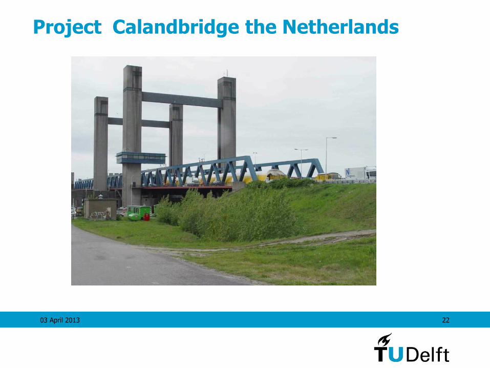
Project Calandbridge the Netherlands

03 April 2013 23
Removal of the asphalt layer
03 April 2013 24
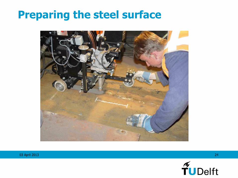
Preparing the steel surface

03 April 2013 25
Applying the epoxy bond layer

03 April 2013 26
Placement of the reinforcement

03 April 2013 27
Leveling the new concrete

03 April 2013 28
Typical characteristics of the new deck
- Thickness of concrete deck 60 mm
- Deck ready for use in 120 hours - Reduction of stress variation of 60% in bearing structure - Reduced vibration and noise

03 April 2013 29
Model Code for Concrete Structures
Concrete’s Design for structural safety Design for serviceability Design for durability Design for sustainability

03 April 2013 30
Model Code: design for sustainability
Concrete’s Level I Method Comparison of green house gas emission: material substitution: BREAM (UK), HQE (France), LEED (USA), CASBEE (Japan), Green Star (Netherlands)
Level II Method Environmental Impact Calculation (EIC): - Measure of Embodied Energy - Measure of CO2 - Calculation of Global Warming Potential (GWP)
Level III Method Full life cycle assessment (LCA), including durability and maintenance considerations, recyle and reuse

03 April 2013 31
EIC: Environmental Impact Calculation
- CO2 Emission - EE = Embodied Energy Energy consumed in the production of Portland Cement is estimated to be 4.88
MJ/kg and the total energy in the production of steel 23.7 MJ/kg
(Struble and Godfrey (2004)
- GWP = Global Warning Potential Contribution of CO2 on global warming, calculated through the equivalence of the effect of greenhouse gas (Elrod, 1999): for simplicity: 100 – year GWP = CO2 + 298 Nox + 25CH4
03 April 2013 32
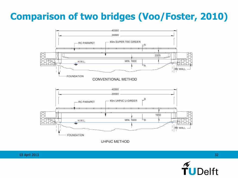
Comparison of two bridges (Voo/Foster, 2010)

03 April 2013 33
Comparison of two bridges
UHPC: - No shear reinforcement only fibres - fcm = 160 MPa

03 April 2013 34
Comparison of two bridges (Voo/Foster 2010)
03 April 2013 35
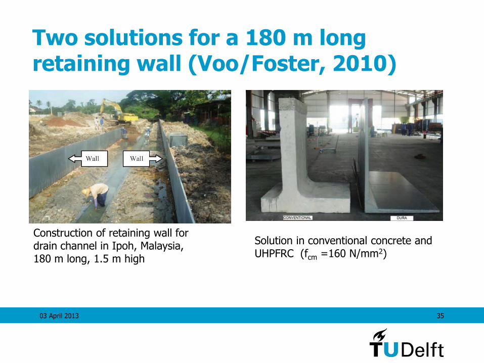
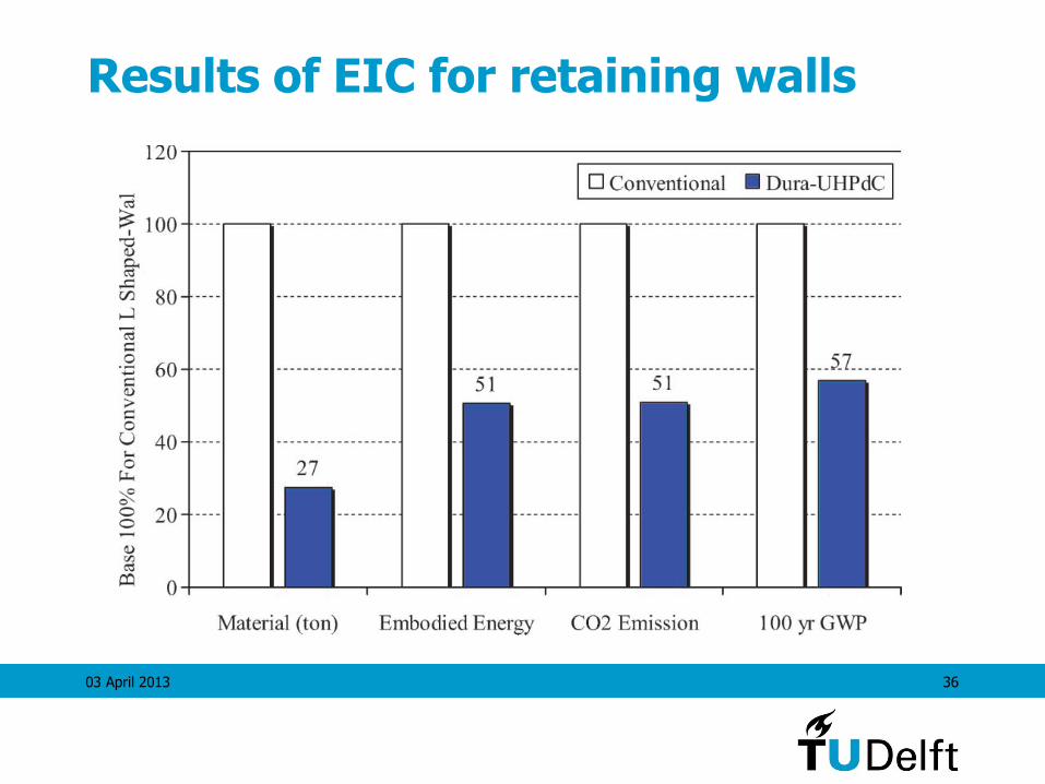
Two solutions for a 180 m long retaining wall (Voo/Foster, 2010)
Construction of retaining wall for drain channel in Ipoh, Malaysia, 180 m long, 1.5 m high
Solution in conventional concrete and UHPFRC (fcm =160 N/mm2)
03 April 2013 36
Results of EIC for retaining walls
03 April 2013 37
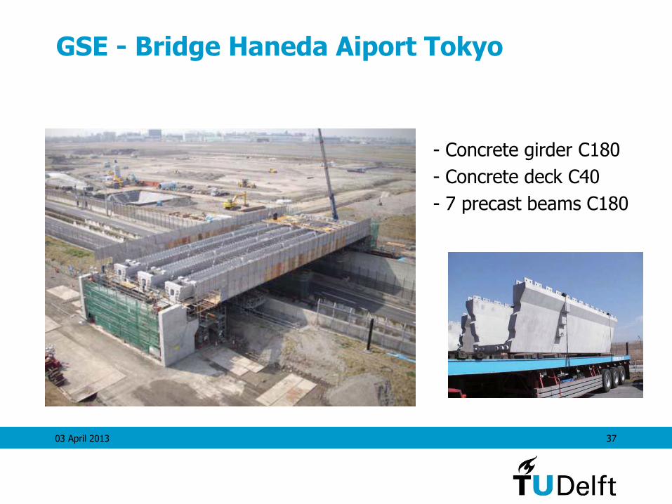
GSE - Bridge Haneda Aiport Tokyo
- Concrete girder C180
- Concrete deck C40
- 7 precast beams C180

03 April 2013 38
GSE Bridge Haneda Airport Tokyo
Advantages of the use of UHPFRC
- 40% Weight reduction
- 20% Reduction of cross-sectional depth (from 2.50 m to 2.00 m)
- Durability

03 April 2013 39
Concrete viaducts the Netherlands
Reduction of height of concrete deck = hughe reduction of soil supply for bridge ramps

03 April 2013 40
Model Code 2010
Design for structural safety Design for serviceability Design for durability Design for sustainability: elegance, beauty, harmony with environment, functionality, social value and acceptance, durability, reduction of nuisance for environment

Glenmore/Legsby pedestrian bridge Canada 2007
Span 53 m Suspended beams 34 m (h = 1,1 m) Crossing 8 traffic lanes Important aspects - Assembly in 8 hours - No intermediate support

03 April 2013 42
Elegant structures in harmony with environment
MuCem Marseille 2012
03 April 2013 43
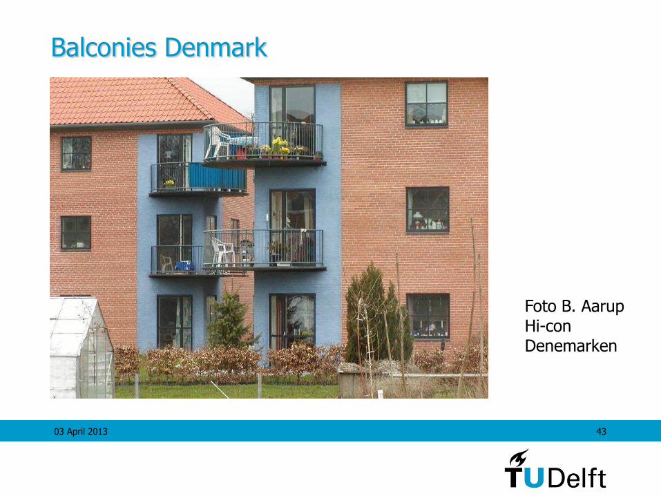
Balconies Denmark
Foto B. Aarup Hi-con Denemarken

Balconies Poptahof Delft 2011
Proofloading 1500 kg/m3

03 April 2013 45
Conclusions
- Adequate design recommendations for UHPFRC are a “must”: MC2010 gives a “level I approach” suitable for any fibre reinforced concrete -- Tailored recommendations (“Level II) are given for traditional concrete (RILEM) en HPFRC (fib TG 8.6) - UHPFRC can play an important role in service life design - UHPFRC is very suitable for retrofitting - Adequate criteria for sustainability of structures can become a hard argument for choosing this material - Architecture and functionality is a winning combination (conceptual design)