Embed Size (px)
Citation preview
Proceedings of the Third International Congress on Construction History, Cottbus, May 2009
INTRODUCTION
The subtitle of Becchi and Foce’s (2002) monumental discussion of masonry arches and vaults may be trans-lated as “mechanics and stereotomy in construction practice”. Becchi makes clear that “stereotomy” implies more than “stone cutting”, and quotes Frézier (1737-9): “The meaning of the words la Coupe des Pierres is not the one that first springs to mind; they do not simply describe the work of the craftsman who dresses the stone, but also the science of the mathematician which has led to the design of the vault, or to an element of a par-ticular shape made by the assembly of many small pieces”. (Author’s translation.) What is at issue is the way the joints should be made between these small pieces of stone. The problem does not seem to arise for the semicircular Roman arch, or at least it is not perceived as a prob-lem by Vitruvius. It was “obvious” that the joints between the voussoirs of such an arch should be radial, all di-rected to the same centre – and the term centering survives for the falsework necessary to support such an arch while it is being built. Radial joints in a circular arch lead to identical wedge-shaped voussoirs; the joints are perpendicular to the stones at both extrados and intrados, and it may perhaps have been thought that all voussoirs, of the same shape, acted in the same way. It is difficult to imagine what precisely was in the minds of the craftsmen; the concept of force, and in particu-lar of inclined force, is sophisticated. Certainly, even if a joint perpendicular to the masonry were thought to be appropriate, there was an immediate difficulty if the extrados and intrados were no longer circles to the same centre – a plane joint could not be constructed to cut both surfaces at right angles. Some input other than the purely geometrical was needed – perhaps the mathematician could give guidance as to how the stones in an arch give each other support, and so give some clue as to the “best” stereotomy. In fact, even for the simple semicircular arch, the voussoirs do not behave identically; the shape of the line of thrust (and the term “line of thrust” must be used carefully, as will be seen) is not that of a semicircle, but may be thought of as Hooke’s inverted hanging chain, and hence intersects the joints at differing inclinations and locations round the arch. Thus the radial joints of a semicircular arch may not be the “best” design. Philippe de La Hire (1695) was one of the first “mathematicians” to discuss the masonry arch; his objective was to try to determine the thrust that an arch exerts against it abutments, and so to design those abutments. It seemed clear that forces between the stones of an arch would be transmitted at right angles to the joints be-tween the stones – on this assumption, he attempted to find the shape of the arch (and derived valuable tools for arch analysis – the force polygon and the funicular polygon). He was forced to the (correct) conclusion that such an arch cannot be designed, and he put the problem aside for seventeen years.
ABSTRACT: The Author discusses the methods of calculation for masonry, and confesses to an error he made in 1969 in the determination of the minimum thickness of a semicircular arch (Couplet’s problem). The correct solution is given. The strength of a masonry structure depends on its stereotomy.
La Coupe des Pierres
Jacques Heyman University of Cambridge, UK
Proceedings of the Third International Congress on Construction History, May 2009
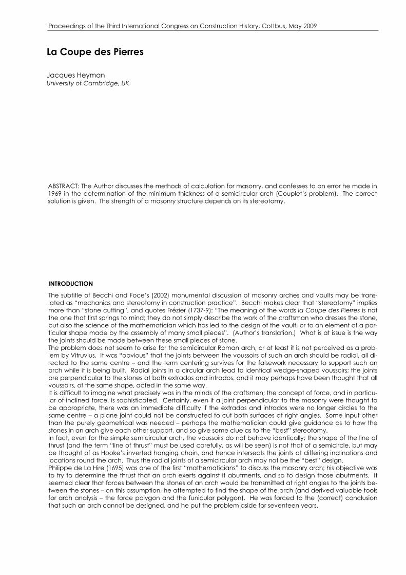
Figure 1: After La Hire (1712); Figure 2: Analysis of fig. 1. At the end of the seventeenth century the phenomenon of friction was under discussion at the Académie – in 1699 Amontons presented, with demonstrations, his famous memoir. In La Hire’s new analysis of the arch, in 1712, he abandoned the assumption that a force transmitted between voussoirs should act normal to the joint – friction would allow the force to be inclined. In order to find the position of that force – that is, to locate the “line of thrust” and so solve the problem of the statics of the arch – La Hire remarked that when the piers of an arch are too weak to carry the thrust, the arch cracks at a section somewhere between the springing and the keystone. In fig. 1 he takes joint LM to be critical, and the block LMF is regarded as a single voussoir, as is the block LMI resting on the pier. Thus, in fig. 2, the thrust P can be found by considering equilibrium of the upper block, and La Hire assumes that the arch thrust acts tangentially to the intrados at the point L. This assumption seems natural, but La Hire gives no comment; nor does he give any rule for locating the critical point L. The definitive early papers on masonry arches are those of Couplet, 1729 and 1730. The first paper explores frictionless behaviour, which Couplet knew not to be helpful, but the second paper makes the explicit assump-tions necessary for a “correct” analysis of masonry – namely that masonry has no tensile strength (the joints be-tween blocks cannot transmit tensile forces), that it has, effectively, infinite compressive strength, and that slid-ing failure cannot occur. Thus friction is introduced into the analysis.
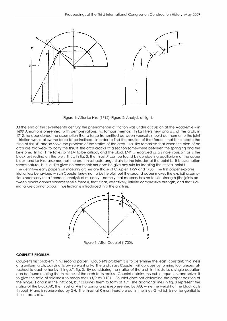
Figure 3: After Couplet (1730).
COUPLET’S PROBLEM
Couplet’s first problem in his second paper (“Couplet’s problem”) is to determine the least (constant) thickness of a uniform arch, carrying its own weight only. The arch, says Couplet, will collapse by forming four pieces, at-tached to each other by “hinges”, fig. 3. By considering the statics of the arch in this state, a single equation can be found relating the thickness of the arch to its radius. Couplet obtains this cubic equation, and solves it to give the ratio of thickness to mean radius t/R as 0.101. Couplet does not determine the proper position of the hinges T and K in the intrados, but assumes them to form at 45º. The additional lines in fig. 3 represent the statics of the block AK; the thrust at A is horizontal and is represented by AG, while the weight of the block acts through H and is represented by GH. The thrust at K must therefore act in the line KG, which is not tangential to the intrados at K.

Proceedings of the Third International Congress on Construction History, May 2009 Heyman “corrected” Couplet’s analysis in 1969 (see also Heyman 1972) using the same mechanism of col-lapse but (a) allowing the position of the intrados hinges to be determined by the mathematics, and (b) ensur-ing that the thrust at these hinges was tangential to the intrados. The value of β in fig. 4 was found to be 58.8º, and the corresponding value of t/R to be 0.106.
Figure 4: Collapse of minimum thickness arch Ochsendorf, in 2006 in a paper of much wider scope, showed that this solution must itself be wrong; and his analysis gave ß = 54.5º and t/R = 0.1075. The three results are tabulated:
ߺ t/R Couplet 1730 45 0.101 Heyman 1969 58.8 0.106 Ochsendorf 2006 54.5 0.1075
PLASTIC PRINCIPLES
The plastic theorems applied to the collapse of a ductile structure require the simultaneous construction of an equilibrium system of forces and of some mechanism of collapse. Ductility of masonry is conferred by the pos-sibility of “hinges” between blocks, and the assumptions of zero tensile strength and infinite compressive strength require that forces passed from block to block must lie within the boundaries of the masonry. A mechanism considered in isolation leads to an unsafe solution; thus the correct value of t/R must certainly be greater than the value 0.101 found by Couplet, who examined only a single mechanism of the type of fig. 4, with ß = 45º. Ochsendorf considered the same mechanism, and allowed the value of ß to vary in order to determine the largest value of t/R (0.1075). At collapse of the arch of minimum thickness the work done in an infinitesimal displacement of the mechanism of fig. 4 is zero, and this gives sufficient information for the value of t/R to be found for any value of ß. In a technical sense Ochsendorf’s solution is incomplete, since he made no study of the statics of the complete arch in the collapse state – what he had determined was the “least unsafe” solu-tion for the class of mechanism of fig. 4. This point is, however, academic; no other class of mechanism exists, and Ochsendorf’s solution is certainly correct. The errors in Couplet’s analysis, which leads to t/R = 0.101, are twofold. First, ß is assumed to be 45º, and sec-ond, the safety of blocks TR and KF (fig. 3) is not examined. The direction of the thrusts at the intrados hinges T and K could well lead to forces passing outside the masonry for these blocks, which is inadmissible. Couplet’s analysis is unsafe since it stems from the assumption of a particular mechanism, even though the calculations were made by statics rather than by writing the work equation. The Author’s (1969) error appears to be more subtle. The same mechanism (fig.4) was assumed, and the analysis was made by resolving forces and taking moments – in short, by satisfying the equations of equilibrium. Since the conditions of mechanism and equilibrium were satisfied simultaneously, the solution t/R = 0.106 should, by the plastic principles, be correct. In detail, the block of the arch between the crown and the radius ß in fig. 4 is acted on by a horizontal thrust at the crown (tangential to the extrados) by a thrust at the intrados hinge tangential to the intrados at that hinge, and by the weight of the block. Similar considerations for the block between the intrados hinge and the foot-ing lead finally to relationships which involve both ß ant t/R. It is found that
2
2
2 cos sin cos sincot
2 cos sin cos sin cos 2,
β β β β β πβ β
β β β β β β+ +
=+ −
(1)
which can be solved numerically to give β = 58.8º, and the resulting value of the thickness found from
( )( )( )sin 1 cos
2 ,1 cos
t
R
β β ββ β
− −=
+ (2)
that is t/R = 0.106.
Proceedings of the Third International Congress on Construction History, May 2009 Since this value of t/R is wrong, and since the mechanism is indisputably a mechanism, the statical analysis must somehow be at fault. The equations (1) and (2) are in fact written correctly – the error lies in the assump-tion that the direction of thrust at the intrados hinges lies tangential to the intrados.
THE LINE OF RESISTANCE AND THE LINE OF PRESSURE
Moseley, in 1839, introduced the terms “line of resistance” and “line of pressure”; the analysis was incorporated in his book Engineering and Architecture published in 1843. The ideas had been formulated a few years earlier by Gerstner (1831), but were explored and deepened by Moseley. The idea of the line of resistance is straight-forward, and is illustrated in Moseley’s diagram, fig. 5. An assemblage of uncemented stones is subjected to certain loads (including self weight), and equilibrium is achieved by (compressive) thrusts passed from stone to stone across their joints. The resultant thrust between the top two stones acts at a, between the next two at b, and so on, and the (curved) line joining these points is defined as the line of resistance. Clearly, if tension at joints is inadmissible, the line of resistance cannot pass outside the masonry. Heyman identified the “line of re-sistance” as the trace of Hooke’s inverted hanging chain, and applied the (loose) label “line of thrust” to the line of resistance. This led to the error in the analysis.
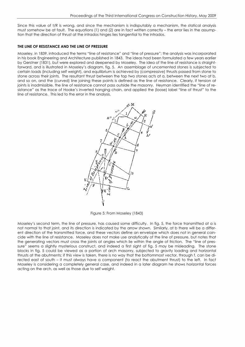
Figure 5: From Moseley (1843)
Moseley’s second term, the line of pressure, has caused some difficulty. In fig. 5, the force transmitted at a is not normal to that joint, and its direction is indicated by the arrow shown. Similarly, at b there will be a differ-ent direction of the transmitted force, and these vectors define an envelope which does not in general coin-cide with the line of resistance. Moseley does not make use analytically of the line of pressure, but notes that the generating vectors must cross the joints at angles which lie within the angle of friction. The “line of pres-sure” seems a slightly mysterious construct, and indeed a first sight of fig. 5 may be misleading. The stone blocks in fig. 5 could be viewed as a portion of arch masonry, subjected to gravity loading and horizontal thrusts at the abutments; if this view is taken, there is no way that the bottommost vector, through f, can be di-rected east of south – it must always have a component (to react the abutment thrust) to the left. In fact Moseley is considering a completely general case, and indeed in a later diagram he shows horizontal forces acting on the arch, as well as those due to self weight.

Proceedings of the Third International Congress on Construction History, May 2009
Figure 6: From Timoshenko (1953) That later commentators have been misled may be illustrated by fig. 6, taken from Timoshenko’s (1953) History of Strength of Materials. The left-hand figure derives from Moseley (fig. 5), as does that on the right, which illus-trates Moseley’s analysis of the minimum thrust H of an arch. The line of resistance is shown tangential to the in-trados at B, and Moseley shows that the value of H will be least when it acts at the extrados, A. Timoshenko in fact calls the dotted line the line of pressure, which it is not, and the fact that the line of resistance is tangential at B does not imply that the thrust vector at B is also tangential. Figure 7 illustrates the statics of the single voussoir at B under the action of self weight and the supporting forces. Although finite the voussoir is taken to be small, so that the two forces shown acting at the intrados are virtually parallel to each other. It is at once evident that these forces cannot act tangentially at B; if moment equilibrium is to be achieved, they must be inclined as sketched in order to provide a restoring moment against the gravity force. Statical analysis of an infinitesimally thin voussoir shows that, in the limit, the direction of the transmitted force at the intrados differs finitely from the direction of the tangent (as indicated in fig. 7). The line of resistance is tangential at B, but the line of pressure lies outside the masonry at that section.
Figure 7: Statics of thin voussoir; Figure 8: Vertical voussoir
LA COUPE DES PIERRES
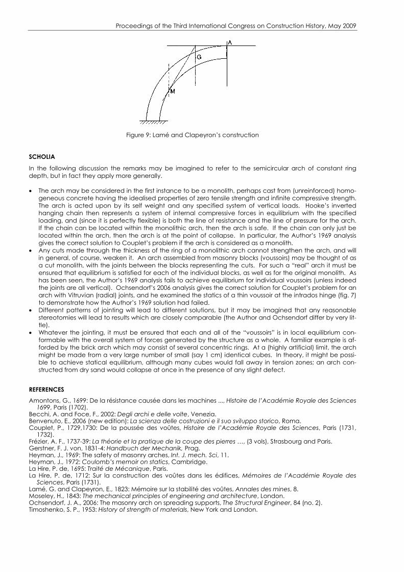
Implicit in this discussion of Couplet’s problem has been the fact that the semicircular arch has radial (Vitru-vian) joints. For example, in Ochsendorf’s work equations the four separate blocks defined by the hinge pat-tern of fig. 4 have prescribed boundaries; the top and bottom surfaces are the extrados and the intrados of the arch, and the other two surfaces are the separating radial joints. The mass of each block is thus defined and Ochsendorf’s analysis led to the value of 0.1075 for t/R. This value is correct for the Couplet arch with radial joints, but different values result if the joints are arranged differently. As an extreme, and improbable, example, if all joints were vertical, then the statics of a (thin) vous-soir adjacent to the intrados hinge leads to the sketch of fig. 8 (cf fig. 7). For equilibrium of this voussoir the transmitted thrust is compelled to be tangential to the intrados, and the Author’s 1969 solution applies uninten-tionally to an arch of this stereotomy. It is of extreme interest that Lamé and Clapeyron in 1823 gave a con-struction for determining the minimum value of the abutment thrust of the general masonry arch. The intrados hinge is located by trial and error by the construction of fig. 9 (reproduced from Benvenuto 2006); the cut at the hinge M is taken by Lamé and Clapeyron to be vertical, and the weight of the upper monolith AM, acting through G, determined correspondingly. In the statical analysis the thrust at the hinge M is truly tangential.
Proceedings of the Third International Congress on Construction History, May 2009
Figure 9: Lamé and Clapeyron’s construction
SCHOLIA
In the following discussion the remarks may be imagined to refer to the semicircular arch of constant ring depth, but in fact they apply more generally. • The arch may be considered in the first instance to be a monolith, perhaps cast from (unreinforced) homo-
geneous concrete having the idealised properties of zero tensile strength and infinite compressive strength. The arch is acted upon by its self weight and any specified system of vertical loads. Hooke’s inverted hanging chain then represents a system of internal compressive forces in equilibrium with the specified loading, and (since it is perfectly flexible) is both the line of resistance and the line of pressure for the arch. If the chain can be located within the monolithic arch, then the arch is safe. If the chain can only just be located within the arch, then the arch is at the point of collapse. In particular, the Author’s 1969 analysis gives the correct solution to Couplet’s problem if the arch is considered as a monolith.
• Any cuts made through the thickness of the ring of a monolithic arch cannot strengthen the arch, and will in general, of course, weaken it. An arch assembled from masonry blocks (voussoirs) may be thought of as a cut monolith, with the joints between the blocks representing the cuts. For such a “real” arch it must be ensured that equilibrium is satisfied for each of the individual blocks, as well as for the original monolith. As has been seen, the Author’s 1969 analysis fails to achieve equilibrium for individual voussoirs (unless indeed the joints are all vertical). Ochsendorf’s 2006 analysis gives the correct solution for Couplet’s problem for an arch with Vitruvian (radial) joints, and he examined the statics of a thin voussoir at the intrados hinge (fig. 7) to demonstrate how the Author’s 1969 solution had failed.
• Different patterns of jointing will lead to different solutions, but it may be imagined that any reasonable stereotomies will lead to results which are closely comparable (the Author and Ochsendorf differ by very lit-tle).
• Whatever the jointing, it must be ensured that each and all of the “voussoirs” is in local equilibrium con-formable with the overall system of forces generated by the structure as a whole. A familiar example is af-forded by the brick arch which may consist of several concentric rings. At a (highly artificial) limit, the arch might be made from a very large number of small (say 1 cm) identical cubes. In theory, it might be possi-ble to achieve statical equilibrium, although many cubes would fall away in tension zones; an arch con-structed from dry sand would collapse at once in the presence of any slight defect.
REFERENCES
Amontons, G., 1699: De la résistance causée dans les machines ..., Histoire de l’Académie Royale des Sciences 1699, Paris (1702).
Becchi, A. and Foce, F., 2002: Degli archi e delle volte, Venezia. Benvenuto, E., 2006 (new edition): La scienza delle costruzioni e il suo sviluppo storico, Roma. Couplet, P., 1729,1730: De la poussée des voûtes, Histoire de l’Académie Royale des Sciences, Paris (1731,
1732). Frézier, A. F., 1737-39: La théorie et la pratique de la coupe des pierres …, (3 vols), Strasbourg and Paris. Gerstner, F. J. von, 1831-4: Handbuch der Mechanik, Prag. Heyman, J., 1969: The safety of masonry arches, Int. J. mech. Sci, 11. Heyman, J., 1972: Coulomb’s memoir on statics, Cambridge. La Hire, P. de, 1695: Traité de Mécanique, Paris. La Hire, P. de, 1712: Sur la construction des voûtes dans les édifices, Mémoires de l’Académie Royale des
Sciences, Paris (1731). Lamé, G. and Clapeyron, E., 1823: Mémoire sur la stabilité des voûtes, Annales des mines, 8. Moseley, H., 1843: The mechanical principles of engineering and architecture, London. Ochsendorf, J. A., 2006: The masonry arch on spreading supports, The Structural Engineer, 84 (no. 2). Timoshenko, S. P., 1953: History of strength of materials, New York and London.