Embed Size (px)
Citation preview

page 1
KOLDWAVEPortable Air Condi� oners
5KK14BEA2AA005KK21BGA2AA005KK30BGA2AA00
SERVICE MANUAL
2 page
Service Manual 5KK14BEA2AA00 / 5KK21BGA2AA00 / 5KK30BGA2AA00
Table of ContentsGENERAL DESCRIPTION..............................................................................4 General air condi� oning system Portable air condi� oning system
SPECIFICATIONS.........................................................................................5 Exterior Dimension Diagram Technical Specifi ca� ons Characteris� cs
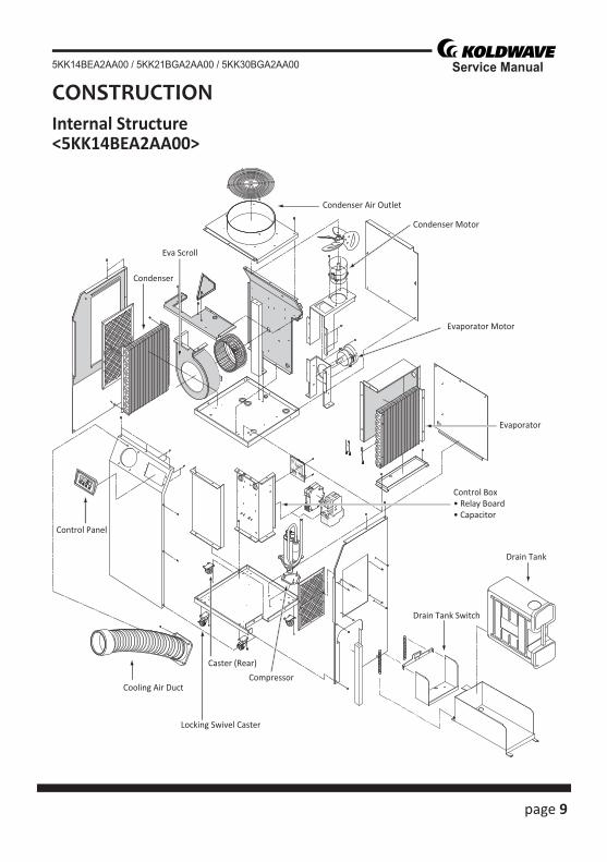
CONSTRUCTION.........................................................................................9 Internal Structure
REFRIGERANT SYSTEM CONSTRUCTION...................................................12 Compressor Compressor lubrica� on Condenser Capillary Tube Evaporator Accumulator
ELECTRICAL SYSTEM.................................................................................18 Circuit Diagram Control panel Program Se� ng Controller Board Control Specifi ca� ons Self-Diagnos� c Codes Compressor Evaporator Fan Motor Condenser Fan Motor Capacitor Molded Case Circuit Breaker Magne� c Contact Thermal Relay Temperature Thermistor Drain Tank Switch
page 3
Service Manual5KK14BEA2AA00 / 5KK21BGA2AA00 / 5KK30BGA2AA00
ASSEMBLY (For 5KK14BEA2AA00).................................................................32 Component parts General Safety Informa� on Troubleshoo� ng chart
ASSEMBLY (For 5KK21BGA2AA00)................................................................33 Component parts General Safety Informa� on Troubleshoo� ng chart
ASSEMBLY (For 5KK30BGA2AA00)................................................................34 Component parts General Safety Informa� on Troubleshoo� ng chart
DISASSEMBLY (For 5KK14BEA2AA00)............................................................38 Disassembly Control panel removal Electrical parts and relay board removal Fan motor removal
DISASSEMBLY (For 5KK21BGA2AA00)...........................................................45 Disassembly Control panel removal Electrical parts and relay board removal Fan motor removal
DISASSEMBLY (For 5KK30BGA2AA00)...........................................................52 Disassembly Control panel removal Electrical parts and relay board removal Fan motor removal
REFRGERANT SYSTEM REPAIR.......................................................................59 Brazing Removal of Refrigerant System Components Charging the System with R-410A Refrigerant Refrigerant Charging Work
4 page
Service Manual 5KK14BEA2AA00 / 5KK21BGA2AA00 / 5KK30BGA2AA00
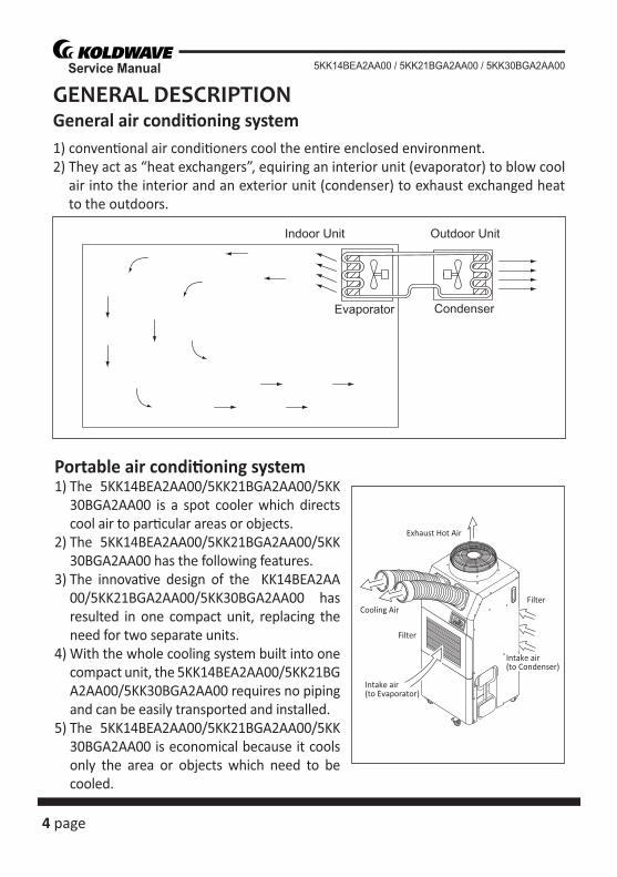
GENERAL DESCRIPTIONGeneral air condi� oning system1) conven� onal air condi� oners cool the en� re enclosed environment.2) They act as “heat exchangers”, equiring an interior unit (evaporator) to blow cool
air into the interior and an exterior unit (condenser) to exhaust exchanged heat to the outdoors.
Portable air condi� oning system1) The 5KK14BEA2AA00/5KK21BGA2AA00/5KK
30BGA2AA00 is a spot cooler which directs cool air to par� cular areas or objects.
2) The 5KK14BEA2AA00/5KK21BGA2AA00/5KK30BGA2AA00 has the following features.
3) The innova� ve design of the KK14BEA2AA00/5KK21BGA2AA00/5KK30BGA2AA00 has resulted in one compact unit, replacing the need for two separate units.
4) With the whole cooling system built into one compact unit, the 5KK14BEA2AA00/5KK21BGA2AA00/5KK30BGA2AA00 requires no piping and can be easily transported and installed.
5) The 5KK14BEA2AA00/5KK21BGA2AA00/5KK30BGA2AA00 is economical because it cools only the area or objects which need to be cooled.
Condenser
Outdoor Unit
Evaporator
Indoor Unit
Intake air(to Evaporator)
Intake air(to Condenser)
Filter
Filter
Exhaust Hot Air
Cooling Air
page 5
Service Manual5KK14BEA2AA00 / 5KK21BGA2AA00 / 5KK30BGA2AA00
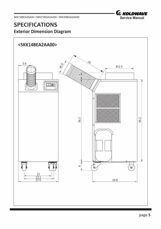
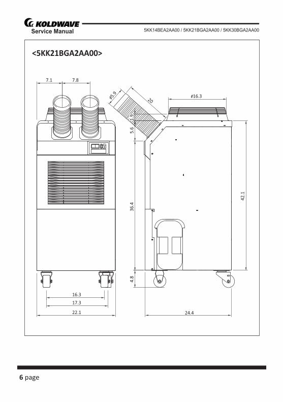
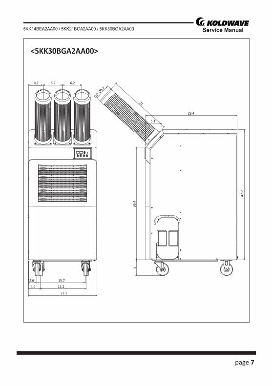
SPECIFICATIONSExterior Dimension Diagram
<5KK14BEA2AA00>
436
.22.
9
12.55.9
36.2
17.5 19.813.112
5.620
6 page
Service Manual 5KK14BEA2AA00 / 5KK21BGA2AA00 / 5KK30BGA2AA00
<5KK21BGA2AA00>
22.1
17.3
16.3
7.87.1
4.8
36.4
5.6
1.9
16.35.9
42.1
20
24.4
page 7
Service Manual5KK14BEA2AA00 / 5KK21BGA2AA00 / 5KK30BGA2AA00
<5KK30BGA2AA00>
4.7 6.2 6.2
2.6 15.7
4.0 15.2
22.1
536
.4
21
OD. Ø5.2
29.4
5.1
42.2
8 page
Service Manual 5KK14BEA2AA00 / 5KK21BGA2AA00 / 5KK30BGA2AA00
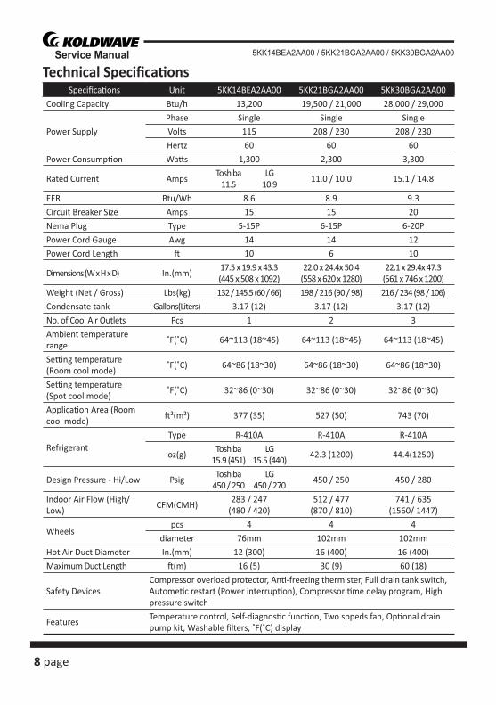
Specifi ca� ons Unit 5KK14BEA2AA00 5KK21BGA2AA00 5KK30BGA2AA00Cooling Capacity Btu/h 13,200 19,500 / 21,000 28,000 / 29,000
Power SupplyPhase Single Single SingleVolts 115 208 / 230 208 / 230Hertz 60 60 60
Power Consump� on Wa� s 1,300 2,300 3,300
Rated Current AmpsToshiba
11.5LG
10.911.0 / 10.0 15.1 / 14.8
EER Btu/Wh 8.6 8.9 9.3Circuit Breaker Size Amps 15 15 20Nema Plug Type 5-15P 6-15P 6-20PPower Cord Gauge Awg 14 14 12Power Cord Length � 10 6 10
Dimensions (W x H x D) In.(mm)17.5 x 19.9 x 43.3(445 x 508 x 1092)
22.0 x 24.4x 50.4(558 x 620 x 1280)
22.1 x 29.4x 47.3(561 x 746 x 1200)
Weight (Net / Gross) Lbs(kg) 132 / 145.5 (60 / 66) 198 / 216 (90 / 98) 216 / 234 (98 / 106)Condensate tank Gallons(Liters) 3.17 (12) 3.17 (12) 3.17 (12)No. of Cool Air Outlets Pcs 1 2 3Ambient temperature range
˚F(˚C) 64~113 (18~45) 64~113 (18~45) 64~113 (18~45)
Se� ng temperature (Room cool mode)
˚F(˚C) 64~86 (18~30) 64~86 (18~30) 64~86 (18~30)
Se� ng temperature (Spot cool mode)
˚F(˚C) 32~86 (0~30) 32~86 (0~30) 32~86 (0~30)
Applica� on Area (Room cool mode)
� ²(m²) 377 (35) 527 (50) 743 (70)
RefrigerantType R-410A R-410A R-410A
oz(g)Toshiba
15.9 (451)LG
15.5 (440)42.3 (1200) 44.4(1250)
Design Pressure - Hi/Low PsigToshiba
450 / 250LG
450 / 270450 / 250 450 / 280
Indoor Air Flow (High/Low)
CFM(CMH)283 / 247
(480 / 420)512 / 477
(870 / 810)741 / 635
(1560/ 1447)
Wheelspcs 4 4 4
diameter 76mm 102mm 102mmHot Air Duct Diameter In.(mm) 12 (300) 16 (400) 16 (400)Maximum Duct Length � (m) 16 (5) 30 (9) 60 (18)
Safety DevicesCompressor overload protector, An� -freezing thermister, Full drain tank switch, Autome� c restart (Power interrup� on), Compressor � me delay program, High pressure switch
FeaturesTemperature control, Self-diagnos� c func� on, Two sppeds fan, Op� onal drain pump kit, Washable fi lters, ˚F(˚C) display
Technical Specifi ca� ons
page 9
Service Manual5KK14BEA2AA00 / 5KK21BGA2AA00 / 5KK30BGA2AA00
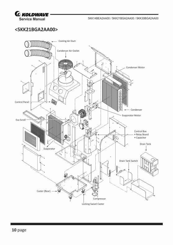
Condenser
Condenser Motor
Evaporator
Cooling Air Duct
Condenser Air Outlet
Control Box• Relay Board• Capacitor
Drain Tank
Drain Tank Switch
Compressor
Locking Swivel Caster
Caster (Rear)
Eva Scroll
Control Panel
Evaporator Motor
CONSTRUCTIONInternal Structure<5KK14BEA2AA00>
10 page
Service Manual 5KK14BEA2AA00 / 5KK21BGA2AA00 / 5KK30BGA2AA00
Control Panel
Eva Scroll
Drain Tank
Drain Tank Switch
Condenser
Condenser Motor
Control Box• Relay Board• Capacitor
Caster (Rear)
Locking Swivel Caster
Compressor
Evaporator
Evaporator Motor
Cooling Air Duct
Condenser Air Outlet
<5KK21BGA2AA00>

page 11
Service Manual5KK14BEA2AA00 / 5KK21BGA2AA00 / 5KK30BGA2AA00
Control Panel
Eva Scroll
Condenser
Control Box• Relay Board• Capacitor
Caster (Rear)Locking Swivel Caster
Compressor
Drain Tank Switch
Drain Tank
EvaporatorEva Filter
Evaporator Motor
Cooling Air Duct
Cowl
<5KK30BGA2AA00>
12 page
Service Manual 5KK14BEA2AA00 / 5KK21BGA2AA00 / 5KK30BGA2AA00
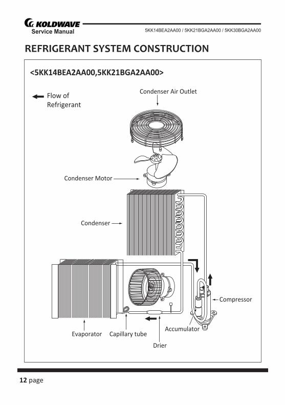
Flow ofRefrigerant
Condenser Air Outlet
Condenser Motor
Compressor
AccumulatorEvaporator Capillary tube
Drier
Condenser
REFRIGERANT SYSTEM CONSTRUCTION
<5KK14BEA2AA00,5KK21BGA2AA00>
page 13
Service Manual5KK14BEA2AA00 / 5KK21BGA2AA00 / 5KK30BGA2AA00
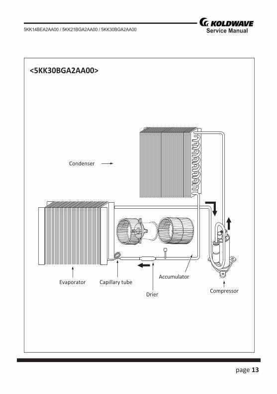
Compressor
AccumulatorEvaporator Capillary tube
Drier
Condenser
<5KK30BGA2AA00>
14 page
Service Manual 5KK14BEA2AA00 / 5KK21BGA2AA00 / 5KK30BGA2AA00
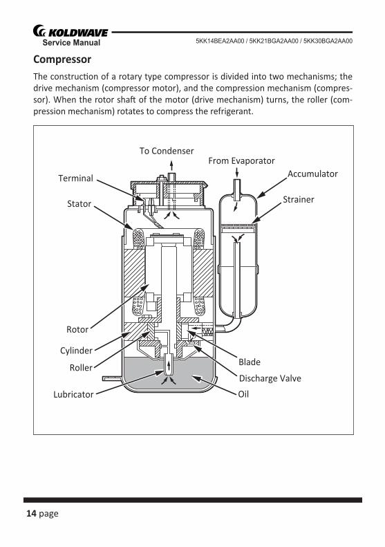
CompressorThe construc� on of a rotary type compressor is divided into two mechanisms; the drive mechanism (compressor motor), and the compression mechanism (compres-sor). When the rotor sha� of the motor (drive mechanism) turns, the roller (com-pression mechanism) rotates to compress the refrigerant.
To Condenser
Accumulator
Strainer
From Evaporator
Blade
Discharge Valve
OilLubricator
Roller
Cylinder
Rotor
Stator
Terminal
page 15
Service Manual5KK14BEA2AA00 / 5KK21BGA2AA00 / 5KK30BGA2AA00
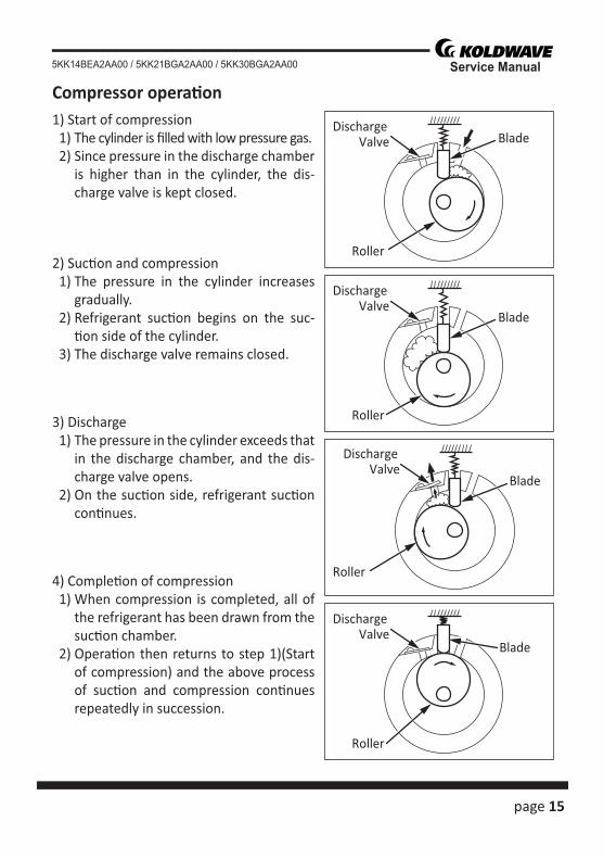
Compressor opera� on1) Start of compression 1) The cylinder is fi lled with low pressure gas. 2) Since pressure in the discharge chamber
is higher than in the cylinder, the dis-charge valve is kept closed.
2) Suc� on and compression 1) The pressure in the cylinder increases
gradually. 2) Refrigerant suc� on begins on the suc-
� on side of the cylinder. 3) The discharge valve remains closed.
3) Discharge 1) The pressure in the cylinder exceeds that
in the discharge chamber, and the dis-charge valve opens.
2) On the suc� on side, refrigerant suc� on con� nues.
4) Comple� on of compression 1) When compression is completed, all of
the refrigerant has been drawn from the suc� on chamber.
2) Opera� on then returns to step 1)(Start of compression) and the above process of suc� on and compression con� nues repeatedly in succession.
BladeDischarge
Valve
Roller
Blade
DischargeValve
Roller
Blade
DischargeValve
Roller
Blade
DischargeValve
Roller
16 page
Service Manual 5KK14BEA2AA00 / 5KK21BGA2AA00 / 5KK30BGA2AA00
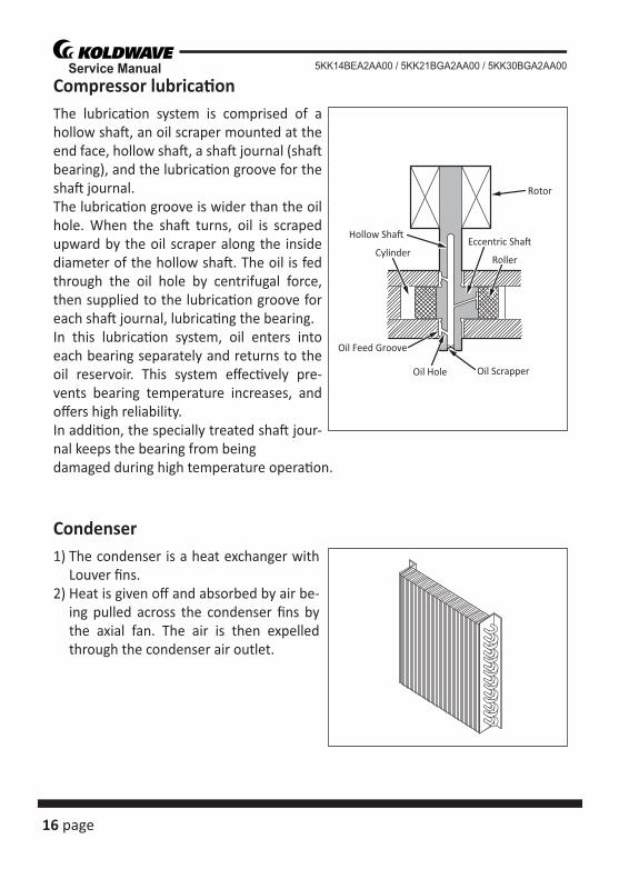
Compressor lubrica� onThe lubrica� on system is comprised of a hollow sha� , an oil scraper mounted at the end face, hollow sha� , a sha� journal (sha� bearing), and the lubrica� on groove for the sha� journal.The lubrica� on groove is wider than the oil hole. When the sha� turns, oil is scraped upward by the oil scraper along the inside diameter of the hollow sha� . The oil is fed through the oil hole by centrifugal force, then supplied to the lubrica� on groove for each sha� journal, lubrica� ng the bearing.In this lubrica� on system, oil enters into each bearing separately and returns to the oil reservoir. This system eff ec� vely pre-vents bearing temperature increases, and off ers high reliability.In addi� on, the specially treated sha� jour-nal keeps the bearing from beingdamaged during high temperature opera� on.
Condenser1) The condenser is a heat exchanger with
Louver fi ns.2) Heat is given off and absorbed by air be-
ing pulled across the condenser fi ns by the axial fan. The air is then expelled through the condenser air outlet.
Oil Feed Groove
Oil Hole Oil Scrapper
Roller
Rotor
Cylinder
Hollow Sha�Eccentric Sha�
page 17
Service Manual5KK14BEA2AA00 / 5KK21BGA2AA00 / 5KK30BGA2AA00
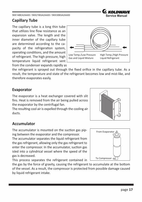
Capillary TubeThe capillary tube is a long thin tube that u� lizes line fl ow resistance as an expansion valve. The length and the inner diameter of the capillary tube are determined according to the ca-pacity of the refrigera� on system, opera� ng condi� ons, and the amount of refrigerant. The high pressure, high temperature liquid refrigerant sent from the condenser expands rapidly as the refrigerant is sprayed out through the fi xed orifi ce in the capillary tube. As a result, the temperature and state of the refrigerant becomes low and mist-like, and therefore evaporates easily.
EvaporatorThe evaporator is a heat exchanger covered with slit fi ns. Heat is removed from the air being pulled across the evaporator by the centrifugal fan.The resul� ng cool air is expelled through the cooling air ducts.
AccumulatorThe accumulator is mounted on the suc� on gas pip-ing between the evaporator and the compressor.The accumulator separates the liquid refrigerant from the gas refrigerant, allowing only the gas refrigerant to enter the compressor. In the accumulator, suc� on gas isled into a cylindrical vessel where the speed of the gas is decreased.This process separates the refrigerant contained in the gas by the force of gravity, causing the refrigerant to accumulate at the bo� om of the vessel. As a result, the compressor is protected from possible damage caused by liquid refrigerant intake.
High Temp./High PressureLiquid Refrigerant
Low Temp./Low PressureGas and Liquid Mixture
From Evaporator
To Compressor
18 page
Service Manual 5KK14BEA2AA00 / 5KK21BGA2AA00 / 5KK30BGA2AA00
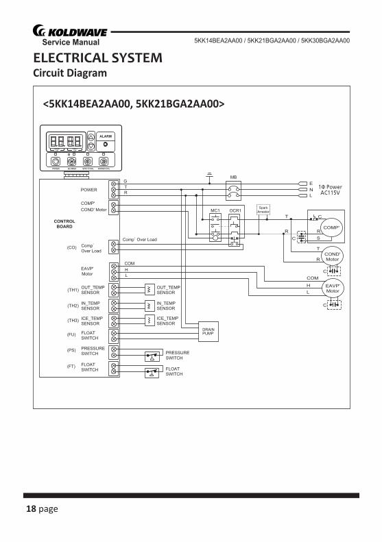
ELECTRICAL SYSTEMCircuit Diagram
<5KK14BEA2AA00, 5KK21BGA2AA00>
(TH1)
(TH2)
(TH3)
DRAINPUMP
page 19
Service Manual5KK14BEA2AA00 / 5KK21BGA2AA00 / 5KK30BGA2AA00
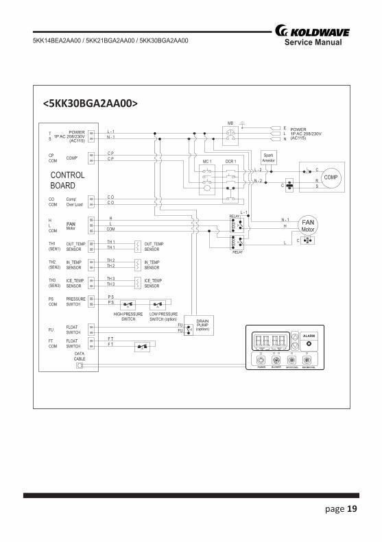
<5KK30BGA2AA00>
DRAINPUMP(option)
RELAY
RELAY
POWER1P AC 208/230V(AC115)
POWER1P AC 208/230V
(AC115)
20 page
Service Manual 5KK14BEA2AA00 / 5KK21BGA2AA00 / 5KK30BGA2AA00
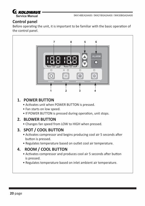
Control panelBefore opera� ng the unit, it is important to be familiar with the basic opera� on of the control panel.
1. POWER BUTTON • Ac� vates unit when POWER BUTTON is pressed. • Fan starts on low speed. • If POWER BUTTON is pressed during opera� on, unit stops.
2. BLOWER BUTTON • Changes fan speed from LOW to HIGH when pressed.
3. SPOT / COOL BUTTON • Ac� vates compressor and begins producing cool air 5 seconds a� er bu� on is pressed. • Regulates temperature based on outlet cool air temperature.
4. ROOM / COOL BUTTON • Ac� vates compressor and produces cool air 5 seconds a� er bu� on is pressed. • Regulates temperature based on inlet ambient air temperature.
1 2
5
3 4
687
page 21
Service Manual5KK14BEA2AA00 / 5KK21BGA2AA00 / 5KK30BGA2AA00
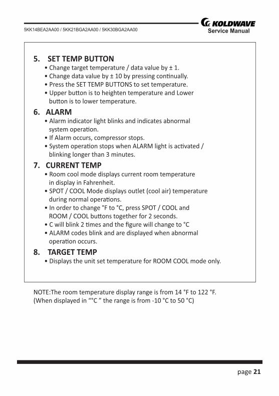
5. SET TEMP BUTTON • Change target temperature / data value by ± 1. • Change data value by ± 10 by pressing con� nually. • Press the SET TEMP BUTTONS to set temperature. • Upper bu� on is to heighten temperature and Lower bu� on is to lower temperature.
6. ALARM • Alarm indicator light blinks and indicates abnormal system opera� on. • If Alarm occurs, compressor stops. • System opera� on stops when ALARM light is ac� vated / blinking longer than 3 minutes.
7. CURRENT TEMP • Room cool mode displays current room temperature in display in Fahrenheit. • SPOT / COOL Mode displays outlet (cool air) temperature during normal opera� ons. • In order to change °F to °C, press SPOT / COOL and ROOM / COOL bu� ons together for 2 seconds. • C will blink 2 � mes and the fi gure will change to °C • ALARM codes blink and are displayed when abnormal opera� on occurs.
8. TARGET TEMP • Displays the unit set temperature for ROOM COOL mode only.
NOTE:The room temperature display range is from 14 °F to 122 °F.(When displayed in “°C ” the range is from -10 °C to 50 °C)
22 page
Service Manual 5KK14BEA2AA00 / 5KK21BGA2AA00 / 5KK30BGA2AA00
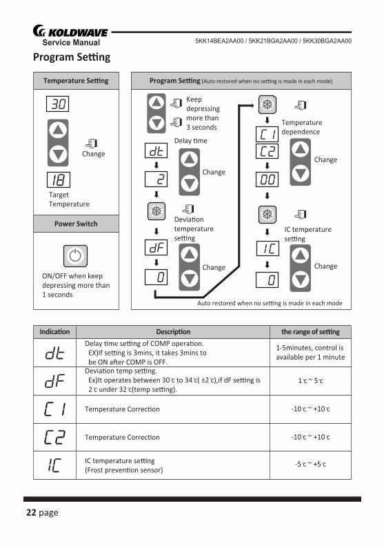
Program Se� ng
Change
Indica�on
Delay �me se�ng of COMP opera�on. EX)If se�ng is 3mins, it takes 3mins to be ON a�er COMP is OFF.Devia�on temp se�ng. Ex)It operates between 30 c to 34 c( ±2 c),if dF se�ng is 2 c under 32 c(temp se�ng).
IC temperature se�ng(Frost preven�on sensor)
Temperature Correc�on
Temperature Correc�on
1-5minutes, control isavailable per 1 minute
1 c ~ 5 c
Descrip�on the range of se�ng
Temperature Se�ng Program Se�ng (Auto restored when no se�ng is made in each mode)
Power Switch
TargetTemperature
ON/OFF when keepdepressing more than1 seconds
Keep depressingmore than 3 seconds
Delay �me
Change
Devia�ontemperaturese�ng
Change
Temperaturedependence
Change
IC temperaturese�ng
Change
Auto restored when no se�ng is made in each mode
-10 c ~ +10 c
-10 c ~ +10 c
-5 c ~ +5 c
page 23
Service Manual5KK14BEA2AA00 / 5KK21BGA2AA00 / 5KK30BGA2AA00
Relay BoardThe relay board contains the compressor and fan on relays, in addi� on to a step-down transformer that converts the line voltage (5KK14BEA2AA00: 115 VAC, 5KK21-BGA2AA00: 208/230, 5KK30BGA2AA00: 208/230 VAC) to 12V. This voltage is then converted from AC to DC and used for relay coil ac� va� on. The 12 V (DC) power is sent to the control panel assembly.
1) Power supply requirements The 5KK14BEA2AA00 requires a single-phase 115 V, 60 Hz power supply, while
the 5KK21BGA2AA00 / 5KK30BGA2AA00 requires a single-phase 208/230 V, 60 Hz power supply.
2) Relay board fuse The relay board fuse is the only serviceable component on the relay board assem-
bly. This fuse provides protec� on against damage to the step-down transformer. The fuse must be replaced with the exact same part, or a suitable equivalent.
Specifi ca� ons : 3.15 A 250 VAC
Failure to use the exact same fuse may result in damage to the unit and/or components, and will also void the unit warranty.CAUTION
24 page
Service Manual 5KK14BEA2AA00 / 5KK21BGA2AA00 / 5KK30BGA2AA00
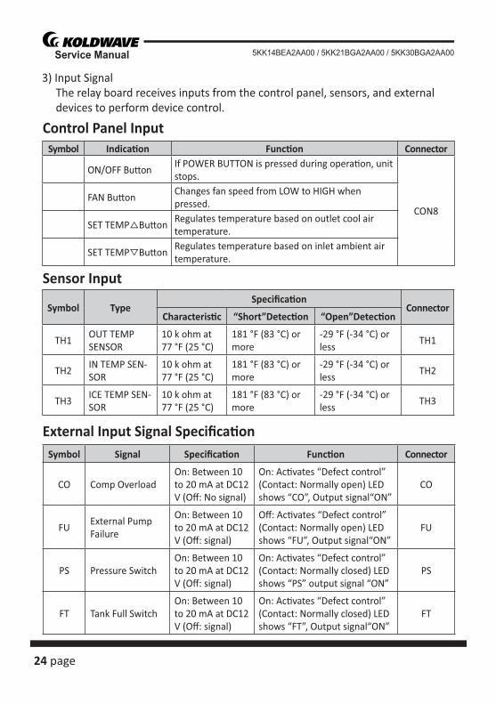
3) Input Signal The relay board receives inputs from the control panel, sensors, and external
devices to perform device control.
Symbol Indica� on Func� on Connector
ON/OFF Bu� onIf POWER BUTTON is pressed during opera� on, unit stops.
CON8FAN Bu� on
Changes fan speed from LOW to HIGH when pressed.
SET TEMP Bu� onRegulates temperature based on outlet cool air temperature.
SET TEMP Bu� onRegulates temperature based on inlet ambient air temperature.
Symbol TypeSpecifi ca� on
ConnectorCharacteris� c “Short”Detec� on “Open”Detec� on
TH1OUT TEMP SENSOR
10 k ohm at 77 °F (25 °C)
181 °F (83 °C) ormore
-29 °F (-34 °C) orless
TH1
TH2IN TEMP SEN-SOR
10 k ohm at 77 °F (25 °C)
181 °F (83 °C) ormore
-29 °F (-34 °C) orless
TH2
TH3ICE TEMP SEN-SOR
10 k ohm at 77 °F (25 °C)
181 °F (83 °C) ormore
-29 °F (-34 °C) orless
TH3
Symbol Signal Specifi ca� on Func� on Connector
CO Comp OverloadOn: Between 10 to 20 mA at DC12 V (Off : No signal)
On: Ac� vates “Defect control”(Contact: Normally open) LED shows “CO”, Output signal“ON”
CO
FUExternal Pump Failure
On: Between 10 to 20 mA at DC12 V (Off : signal)
Off : Ac� vates “Defect control”(Contact: Normally open) LED shows “FU”, Output signal“ON”
FU
PS Pressure SwitchOn: Between 10 to 20 mA at DC12 V (Off : signal)
On: Ac� vates “Defect control”(Contact: Normally closed) LED shows “PS” output signal “ON”
PS
FT Tank Full SwitchOn: Between 10 to 20 mA at DC12 V (Off : signal)
On: Ac� vates “Defect control”(Contact: Normally closed) LED shows “FT”, Output signal“ON”
FT
Control Panel Input
Sensor Input
External Input Signal Specifi ca� on
page 25
Service Manual5KK14BEA2AA00 / 5KK21BGA2AA00 / 5KK30BGA2AA00
Control Specifi ca� ons1) EVAPORATOR FAN MOTOR• When the BLOWER bu� on is pressed, the RL1/3 (fan motor HI/LOW) relay on the
relay board turns on, opera� ng the fan.
Specifi ca� ons:- RL1/3 (Fan motor HI-LOW) relay output: 10 A at AC 250 V
2) Compressor start control• When the ON/OFF bu� on is pressed, the RL4 relay on the relay board turns on,
opera� ng the compressor.
Specifi ca� ons:- RL4 (Compressor On-Off ) relay output: 5 A at AC 250 V
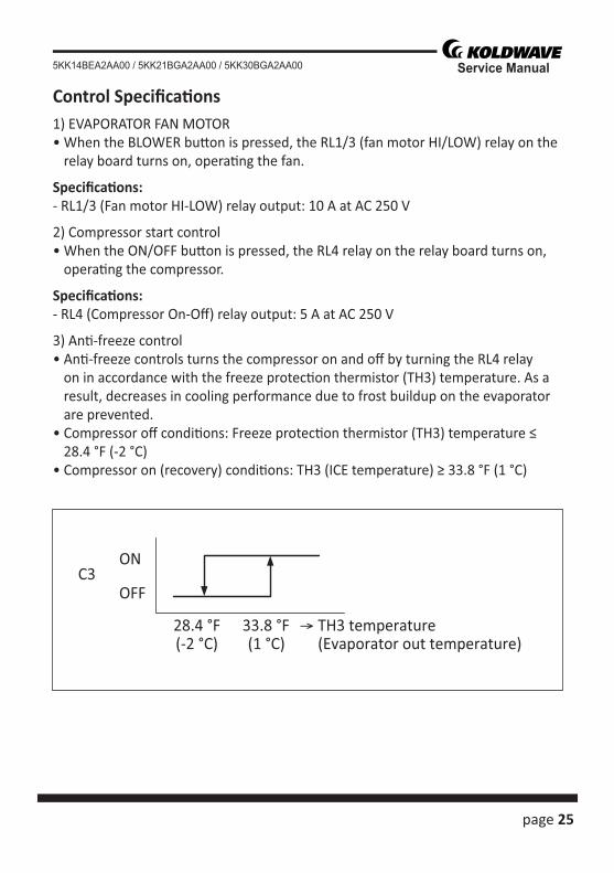
3) An� -freeze control• An� -freeze controls turns the compressor on and off by turning the RL4 relay
on in accordance with the freeze protec� on thermistor (TH3) temperature. As a result, decreases in cooling performance due to frost buildup on the evaporator are prevented.
• Compressor off condi� ons: Freeze protec� on thermistor (TH3) temperature ≤ 28.4 °F (-2 °C)
• Compressor on (recovery) condi� ons: TH3 (ICE temperature) ≥ 33.8 °F (1 °C)
ON
OFFC3
28.4 °F(-2 °C)
33.8 °F(1 °C)
TH3 temperature(Evaporator out temperature)
26 page
Service Manual 5KK14BEA2AA00 / 5KK21BGA2AA00 / 5KK30BGA2AA00
4) Compressor � me delay control (compressor protec� on) Compressor protec� on consists of a � me delay program within the microproces-
sor. This program prevents a heavy load from being applied to the compressor motor when restar� ng the unit (room/cool mode or spot/cool mode) a� er a very short period of � me. This “delay” is in eff ect any � me the compressor is turned on by either the POWER ON/OFF bu� on or ROOM/COOL or SPOT/COOL ON/OFF bu� on.
Specifi ca� ons:- Time Delay: 120 sec.
5) Automa� c restart and recovery func� on• The microprocessor contains a feature that automa� cally restart the unit a� er
power is lost and regained, and also has memory to store and recover opera� on status in the even of a power loss.
Status of memory during power interrup� on• When the input power is off , the status items below are saved in the memory. - Running status (on or off ) - Opera� ng mode: Cool mode or fan only mode - Set temperature - Temperature mode (°F or °C)
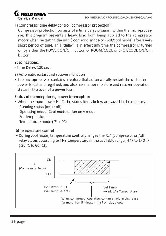
6) Temperature control• During cool mode, temperature control changes the RL4 (compressor on/off )
relay status according to TH3 temperature in the available range(-4 °F to 140 °F (-20 °C to 60 °C)).
ON
OFF
RL4(Compressor Relay)
(Set Temp. -3 °F)(Set Temp. -1.7 °C)
Set Temp Inlet Air Temperature
When compressor opera�on con�nues within this rangefor more than 5 minutes, the RL4 relay stops.
page 27
Service Manual5KK14BEA2AA00 / 5KK21BGA2AA00 / 5KK30BGA2AA00
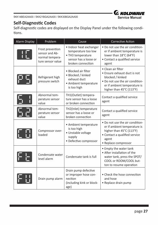
Alarm Display Problem Cause Correc� ve Ac� on
Frost preven� on sensor and Ab-normal tempera-ture sensor value
• Indoor heat exchanger temperature too low
• TH3 temperature sensor has a loose or broken connec� on
• Do not use the air condi� on-er if ambient temperature is lower than 18°C (64°F)
• Contact a qualifi ed service agent
Refrigerant highpressure switch
• Blocked air fi lter• Blocked / kinked
exhaust duct• Ambient temperature
is too high
• Clean air fi lter• Ensure exhaust duct is not
blocked / kinked• Do not use the air condi� on-
er if ambient temperature is higher than 45°C (113°F)
Abnormal tem-perature sensor value
TH1(Outlet) tempera-ture sensor has a loose or broken connec� on
Contact a qualifi ed service agent
Abnormal tem-perature sensor value
TH2(Inlet) temperature sensor has a loose or broken connec� on
Contact a qualifi ed service agent
Compressor over-loaded
• Ambient temperature is too high
• Unstable voltage supply
• Defec� ve compressor
• Do not use the air condi� on-er if ambient temperature is higher than 45°C (113°F)
• Contact a qualifi ed service agent
• Replace compressor
Condensate water level alarm
Condensate tank is full
• Empty the water tank• A� er installa� on of the
water tank, press the SPOT/COOL or ROOM/COOL but-ton to resume opera� on
Drain pump alarm
Drain pump defec� ve or improper hose con-nec� on(including kink or block-age)
• Check the hose connec� on and hose
• Replace drain pump
Self-Diagnos� c CodesSelf-diagnos� c codes are displayed on the Display Panel under the following condi-� ons.
28 page
Service Manual 5KK14BEA2AA00 / 5KK21BGA2AA00 / 5KK30BGA2AA00
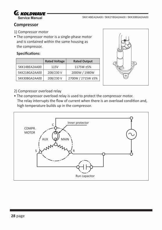
Compressor1) Compressor motor• The compressor motor is a single-phase motor and is contained within the same housing as the compressor.
Specifi ca� ons:
2) Compressor overload relay• The compressor overload relay is used to protect the compressor motor.
The relay interrupts the fl ow of current when there is an overload condi� on and, high temperature builds up in the compressor.
Rated Voltage Rated Output
5KK14BEA2AA00 115V 1175W ±5%
5KK21BGA2AA00 208/230 V 2000W / 1980W
5KK30BGA2AA00 208/230 V 2700W / 2715W ±5%
Run capacitor
AUX MAIN
RS
CCOMPR.MOTOR
Inner protector
page 29
Service Manual5KK14BEA2AA00 / 5KK21BGA2AA00 / 5KK30BGA2AA00
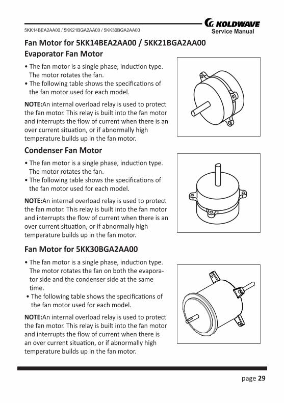
Evaporator Fan Motor• The fan motor is a single phase, induc� on type. The motor rotates the fan.• The following table shows the specifi ca� ons of the fan motor used for each model.
NOTE:An internal overload relay is used to protectthe fan motor. This relay is built into the fan motorand interrupts the fl ow of current when there is anover current situa� on, or if abnormally hightemperature builds up in the fan motor.
• The fan motor is a single phase, induc� on type. The motor rotates the fan on both the evapora-tor side and the condenser side at the same � me.
• The following table shows the specifi ca� ons of the fan motor used for each model.
NOTE:An internal overload relay is used to protect the fan motor. This relay is built into the fan motor and interrupts the fl ow of current when there is an over current situa� on, or if abnormally high temperature builds up in the fan motor.
Condenser Fan Motor• The fan motor is a single phase, induc� on type. The motor rotates the fan.• The following table shows the specifi ca� ons of the fan motor used for each model.
NOTE:An internal overload relay is used to protectthe fan motor. This relay is built into the fan motorand interrupts the fl ow of current when there is anover current situa� on, or if abnormally hightemperature builds up in the fan motor.
Fan Motor for 5KK14BEA2AA00 / 5KK21BGA2AA00
Fan Motor for 5KK30BGA2AA00
30 page
Service Manual 5KK14BEA2AA00 / 5KK21BGA2AA00 / 5KK30BGA2AA00
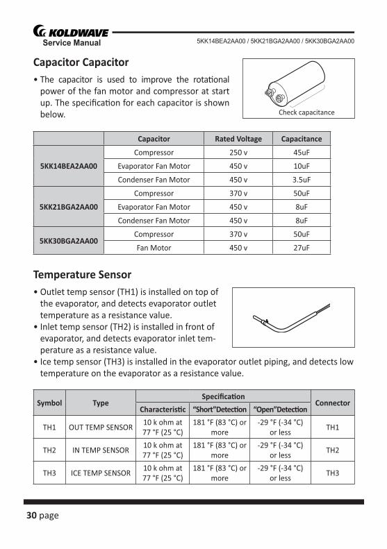
Capacitor Capacitor• The capacitor is used to improve the rota� onal
power of the fan motor and compressor at start up. The specifi ca� on for each capacitor is shown below.
Temperature Sensor• Outlet temp sensor (TH1) is installed on top of
the evaporator, and detects evaporator outlet temperature as a resistance value.
• Inlet temp sensor (TH2) is installed in front of evaporator, and detects evaporator inlet tem-perature as a resistance value.
• Ice temp sensor (TH3) is installed in the evaporator outlet piping, and detects low temperature on the evaporator as a resistance value.
Check capacitance
Capacitor Rated Voltage Capacitance
5KK14BEA2AA00
Compressor 250 v 45uF
Evaporator Fan Motor 450 v 10uF
Condenser Fan Motor 450 v 3.5uF
5KK21BGA2AA00
Compressor 370 v 50uF
Evaporator Fan Motor 450 v 8uF
Condenser Fan Motor 450 v 8uF
5KK30BGA2AA00Compressor 370 v 50uF
Fan Motor 450 v 27uF
Symbol TypeSpecifi ca� on
ConnectorCharacteris� c “Short”Detec� on “Open”Detec� on
TH1 OUT TEMP SENSOR10 k ohm at 77 °F (25 °C)
181 °F (83 °C) or more
-29 °F (-34 °C) or less
TH1
TH2 IN TEMP SENSOR10 k ohm at 77 °F (25 °C)
181 °F (83 °C) or more
-29 °F (-34 °C) or less
TH2
TH3 ICE TEMP SENSOR10 k ohm at 77 °F (25 °C)
181 °F (83 °C) or more
-29 °F (-34 °C) or less
TH3
page 31
Service Manual5KK14BEA2AA00 / 5KK21BGA2AA00 / 5KK30BGA2AA00
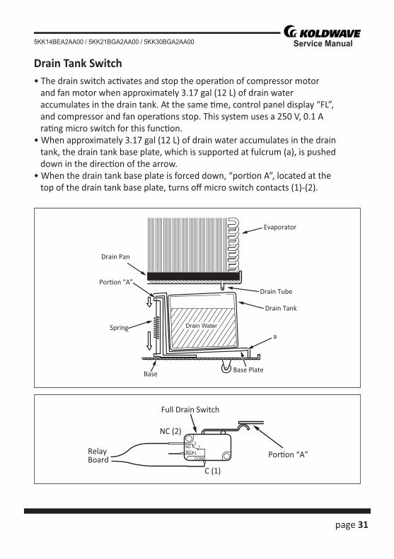
Drain Tank Switch• The drain switch ac� vates and stop the opera� on of compressor motor and fan motor when approximately 3.17 gal (12 L) of drain water accumulates in the drain tank. At the same � me, control panel display “FL”, and compressor and fan opera� ons stop. This system uses a 250 V, 0.1 A ra� ng micro switch for this func� on.• When approximately 3.17 gal (12 L) of drain water accumulates in the drain tank, the drain tank base plate, which is supported at fulcrum (a), is pushed down in the direc� on of the arrow.• When the drain tank base plate is forced down, “por� on A”, located at the top of the drain tank base plate, turns off micro switch contacts (1)-(2).
Evaporator
Drain Pan
Por�on “A”
Spring
Drain Tube
Drain Water
Base
Drain Tank
Base Plate
a
Full Drain Switch
Por�on “A”RelayBoard
12
3NC
COM
NO
C (1)
NC (2)
32 page
Service Manual 5KK14BEA2AA00 / 5KK21BGA2AA00 / 5KK30BGA2AA00
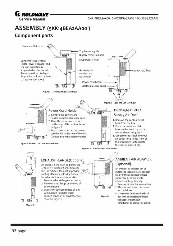
ASSEMBLY (5KK14BEA2AA00 )Component parts
Cool air outlet hose
Display / Control boardTop fan wire grille
Evaporator / filter
Guide bar for condensatewater tank
Figure 1 – Front and Right Side View
Condenser / filter
Figure 2 – Rear and Le� Side View
Power cord holderElectrical access panel
Casters
Figure 3 – Power Cord Holder a�achment
Figure 4 – Cool Air Outlet a�achment
Figure 5
Figure 6
An exhaust flange can be purchased separately. Exhaust flange fits over the top exhaust fan duct improvingcooling efficiency, allowing hot air to be exhausted to another loca�on.1. Remove exhaust flange from carton.2. Place exhaust flange on the top of air condi�oner.3. Use screws (enclosed inside of box with exhaust flange) to install exhaust flange on air condi�oner as shown in Figure 5.
An ambient air adapter can be purchased separately. Air adapter fits over the condenser to duct condenser air to the unit to improve cooling efficiency.1. Remove air adapter from carton.2. Place air adapter on the side of air condi�oner.3. Use screws (enclosed inside of box with air adapter) to install the adapter on the air condi�oner as shown in Figure 6.
1. Remove the power cord holder from the accessory pack2. Place the power cord holder on the rear of the unit as shown in Figure 33. Use screws to install the power cord holder to the rear of the unit (screws inside the accessory pack)
1. Remove the cool air outlet hose from the box2. Place the cool air outlet hose on the front top of the unit as shown in Figure 43. Use screws to install the cool air outlet hose to the front of the unit (screws a�ached to the cool air outlet hose)
Condensate water tank(Water level is sensed, and the unit opera�on is stopped when tank is full. An alarm will be displayed. Empty the tank and replace to resume opera�on)
Power Cord Holder Discharge Ducts /Supply Air Duct
EXHAUST FLANGE(Op�onal) AMBIENT AIR ADAPTER(Op�onal)
page 33
Service Manual5KK14BEA2AA00 / 5KK21BGA2AA00 / 5KK30BGA2AA00
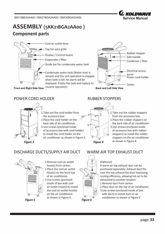
ASSEMBLY (5KK21BGA2AA00 )Component parts
Cool air outlet hose
Front and Right Side View
Display / Control board
Top fan wire grille
Evaporator / filter
Guide bar for condensate water tank
Condensate water tank (Water level issensed, and the unit opera�on is stoppedwhen tank is full. An alarm will bedisplayed. Empty the tank and replace toresume opera�on)
1.Take out the cord holder from the accessory box.2.Place the cord holder on the back side of air condi�oner.3.Use screws (enclosed inside of accessory box with cord holder) to install the cord holder on the air condi�oner as shown in Figure 3.
1.Remove cool air outlet hose(s) from carton.2.Place the cool air outlet hose(s) on the front top of air condi�oner.3.Use screws (enclosed inside of box with cool air outlet hose(s) to install the cool air outlet hose(s) on the air condi�oner as shown in Figure 5.
(Op�onal)A warm air top exhaust duct can bepurchased separately. Exhaust duct fitsover the top exhaust fan duct improvingcooling efficiency, allowing hot air to beexhausted to another loca�on.1.Remove duct from carton.2.Place duct on the top of air condi�oner.3.Use screws (enclosed inside of box with duct) to install duct on air condi�oner as shown in Figure 6.
1.Take out the rubber stoppers from the accessory box.2.Place the rubber stoppers on the back side of air condi�oner.3.Use screws (enclosed inside of accessory box with rubber stoppers) to install the rubber stoppers on the air condi�oner as shown in Figure 4.
POWER CORD HOLDER RUBBER STOPPERS
DISCHARGE DUCTS/SUPPLY AIR DUCT WARM AIR TOP EXHAUST DUCT
Side handleRubber stopper
Back and Left Side View
Condenser / filter
Power cord holder
Caster
Electrical accesspanel
Figure 3 Figure 4
Figure 5 Figure 6
34 page
Service Manual 5KK14BEA2AA00 / 5KK21BGA2AA00 / 5KK30BGA2AA00
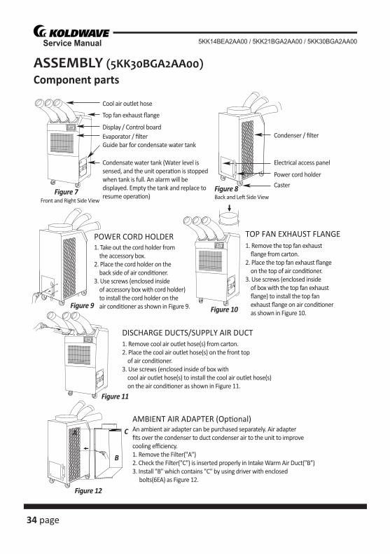
ASSEMBLY (5KK30BGA2AA00)Component parts
Cool air outlet hose
Front and Right Side View
Display / Control board
Top fan exhaust flange
Evaporator / filterGuide bar for condensate water tank
Condensate water tank (Water level issensed, and the unit opera�on is stoppedwhen tank is full. An alarm will bedisplayed. Empty the tank and replace toresume opera�on)
1. Take out the cord holder from the accessory box.2. Place the cord holder on the back side of air condi�oner.3. Use screws (enclosed inside of accessory box with cord holder) to install the cord holder on the air condi�oner as shown in Figure 9.
1. Remove cool air outlet hose(s) from carton.2. Place the cool air outlet hose(s) on the front top of air condi�oner.3. Use screws (enclosed inside of box with cool air outlet hose(s) to install the cool air outlet hose(s) on the air condi�oner as shown in Figure 11.
POWER CORD HOLDER
DISCHARGE DUCTS/SUPPLY AIR DUCT
Figure 8Figure 7
Figure 9
Figure 11
Figure 12
A
B
C
Back and Le� Side View
Condenser / filter
Power cord holder
Caster
Electrical access panel
1. Remove the top fan exhaust flange from carton.2. Place the top fan exhaust flange on the top of air condi�oner.3. Use screws (enclosed inside of box with the top fan exhaust flange) to install the top fan exhaust flange on air condi�oner as shown in Figure 10.
TOP FAN EXHAUST FLANGE
Figure 10
An ambient air adapter can be purchased separately. Air adapter fits over the condenser to duct condenser air to the unit to improve cooling efficiency.1. Remove the Filter("A")2. Check the Filter("C") is inserted properly in Intake Warm Air Duct("B")3. Install "B" which contains "C" by using driver with enclosed bolts(6EA) as Figure 12.
AMBIENT AIR ADAPTER (Op�onal)
page 35
Service Manual5KK14BEA2AA00 / 5KK21BGA2AA00 / 5KK30BGA2AA00
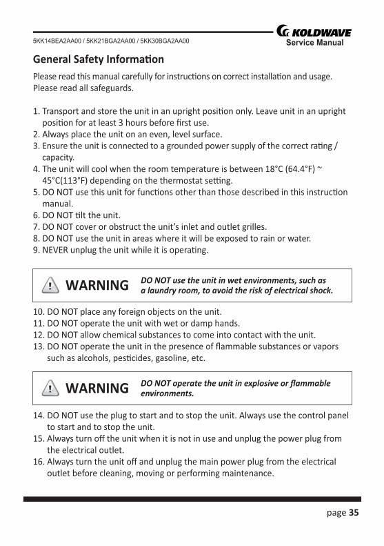
General Safety Informa� onPlease read this manual carefully for instruc� ons on correct installa� on and usage. Please read all safeguards.
1. Transport and store the unit in an upright posi� on only. Leave unit in an upright posi� on for at least 3 hours before fi rst use.
2. Always place the unit on an even, level surface.3. Ensure the unit is connected to a grounded power supply of the correct ra� ng /
capacity.4. The unit will cool when the room temperature is between 18°C (64.4°F) ~
45°C(113°F) depending on the thermostat se� ng.5. DO NOT use this unit for func� ons other than those described in this instruc� on
manual.6. DO NOT � lt the unit.7. DO NOT cover or obstruct the unit’s inlet and outlet grilles.8. DO NOT use the unit in areas where it will be exposed to rain or water.9. NEVER unplug the unit while it is opera� ng.
10. DO NOT place any foreign objects on the unit.11. DO NOT operate the unit with wet or damp hands.12. DO NOT allow chemical substances to come into contact with the unit.13. DO NOT operate the unit in the presence of fl ammable substances or vapors
such as alcohols, pes� cides, gasoline, etc.
14. DO NOT use the plug to start and to stop the unit. Always use the control panel to start and to stop the unit.
15. Always turn off the unit when it is not in use and unplug the power plug from the electrical outlet.
16. Always turn the unit off and unplug the main power plug from the electrical outlet before cleaning, moving or performing maintenance.
DO NOT use the unit in wet environments, such asa laundry room, to avoid the risk of electrical shock.
DO NOT operate the unit in explosive or fl ammableenvironments.
WARNING
WARNING
36 page
Service Manual 5KK14BEA2AA00 / 5KK21BGA2AA00 / 5KK30BGA2AA00
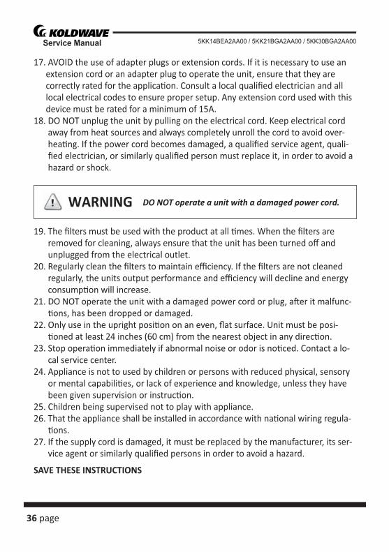
17. AVOID the use of adapter plugs or extension cords. If it is necessary to use an extension cord or an adapter plug to operate the unit, ensure that they are correctly rated for the applica� on. Consult a local qualifi ed electrician and all local electrical codes to ensure proper setup. Any extension cord used with this device must be rated for a minimum of 15A.
18. DO NOT unplug the unit by pulling on the electrical cord. Keep electrical cord away from heat sources and always completely unroll the cord to avoid over-hea� ng. If the power cord becomes damaged, a qualifi ed service agent, quali-fi ed electrician, or similarly qualifi ed person must replace it, in order to avoid a hazard or shock.
19. The fi lters must be used with the product at all � mes. When the fi lters are removed for cleaning, always ensure that the unit has been turned off and unplugged from the electrical outlet.
20. Regularly clean the fi lters to maintain effi ciency. If the fi lters are not cleaned regularly, the units output performance and effi ciency will decline and energy consump� on will increase.
21. DO NOT operate the unit with a damaged power cord or plug, a� er it malfunc-� ons, has been dropped or damaged.
22. Only use in the upright posi� on on an even, fl at surface. Unit must be posi-� oned at least 24 inches (60 cm) from the nearest object in any direc� on.
23. Stop opera� on immediately if abnormal noise or odor is no� ced. Contact a lo-cal service center.
24. Appliance is not to used by children or persons with reduced physical, sensory or mental capabili� es, or lack of experience and knowledge, unless they have been given supervision or instruc� on.
25. Children being supervised not to play with appliance.26. That the appliance shall be installed in accordance with na� onal wiring regula-
� ons.27. If the supply cord is damaged, it must be replaced by the manufacturer, its ser-
vice agent or similarly qualifi ed persons in order to avoid a hazard.
SAVE THESE INSTRUCTIONS
DO NOT operate a unit with a damaged power cord.WARNING
page 37
Service Manual5KK14BEA2AA00 / 5KK21BGA2AA00 / 5KK30BGA2AA00
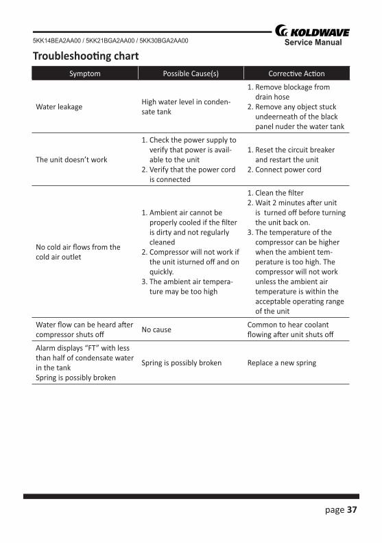
Troubleshoo� ng chartSymptom Possible Cause(s) Correc� ve Ac� on
Water leakageHigh water level in conden-sate tank
1. Remove blockage from drain hose
2. Remove any object stuck undeerneath of the black panel nuder the water tank
The unit doesn’t work
1. Check the power supply to verify that power is avail-able to the unit
2. Verify that the power cord is connected
1. Reset the circuit breaker and restart the unit
2. Connect power cord
No cold air fl ows from the cold air outlet
1. Ambient air cannot be properly cooled if the fi lter is dirty and not regularly cleaned
2. Compressor will not work if the unit isturned off and on quickly.
3. The ambient air tempera-ture may be too high
1. Clean the fi lter2. Wait 2 minutes a� er unit
is turned off before turning the unit back on.
3. The temperature of the compressor can be higher when the ambient tem-perature is too high. The compressor will not work unless the ambient air temperature is within the acceptable opera� ng range of the unit
Water fl ow can be heard a� er compressor shuts off
No causeCommon to hear coolant fl owing a� er unit shuts off
Alarm displays “FT” with less than half of condensate water in the tankSpring is possibly broken
Spring is possibly broken Replace a new spring
38 page
Service Manual 5KK14BEA2AA00 / 5KK21BGA2AA00 / 5KK30BGA2AA00
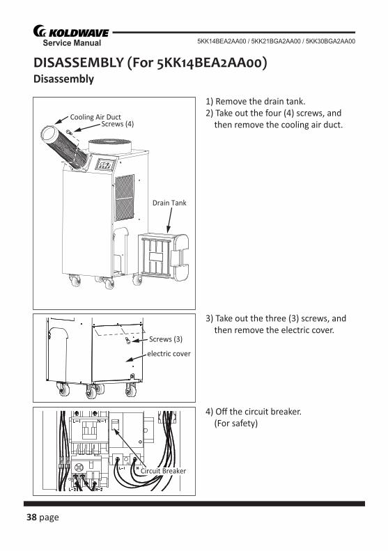
DISASSEMBLY (For 5KK14BEA2AA00)Disassembly
1) Remove the drain tank.2) Take out the four (4) screws, and then remove the cooling air duct.
3) Take out the three (3) screws, and then remove the electric cover.
4) Off the circuit breaker. (For safety)
Cooling Air DuctScrews (4)
Drain Tank
Screws (3)
electric cover
Circuit Breaker
page 39
Service Manual5KK14BEA2AA00 / 5KK21BGA2AA00 / 5KK30BGA2AA00
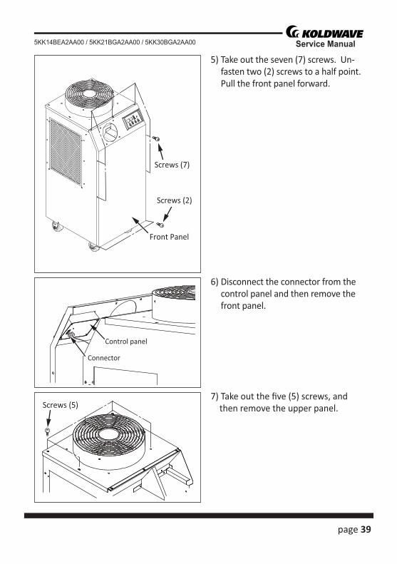
5) Take out the seven (7) screws. Un-fasten two (2) screws to a half point. Pull the front panel forward.
6) Disconnect the connector from the control panel and then remove the front panel.
7) Take out the fi ve (5) screws, and then remove the upper panel.
Screws (7)
Screws (2)
Front Panel
Connector
Control panel
Screws (5)
40 page
Service Manual 5KK14BEA2AA00 / 5KK21BGA2AA00 / 5KK30BGA2AA00
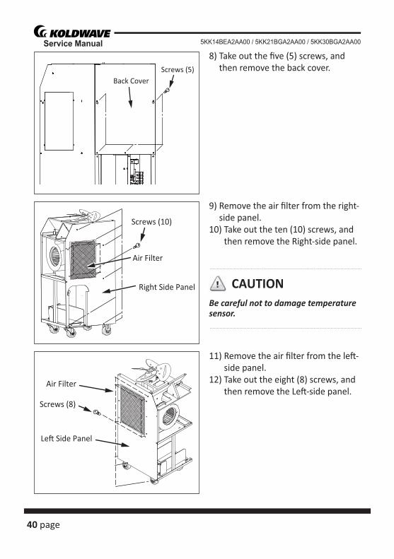
8) Take out the fi ve (5) screws, and then remove the back cover.
9) Remove the air fi lter from the right-side panel.
10) Take out the ten (10) screws, and then remove the Right-side panel.
11) Remove the air fi lter from the le� -side panel.
12) Take out the eight (8) screws, and then remove the Le� -side panel.
Screws (5)Back Cover
Screws (10)
Right Side Panel
Air Filter
Screws (8)
Le� Side Panel
Air Filter
Be careful not to damage temperaturesensor.
CAUTION
page 41
Service Manual5KK14BEA2AA00 / 5KK21BGA2AA00 / 5KK30BGA2AA00
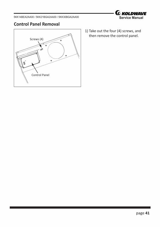
1) Take out the four (4) screws, and then remove the control panel.
Screws (4)
Control Panel
Control Panel Removal
42 page
Service Manual 5KK14BEA2AA00 / 5KK21BGA2AA00 / 5KK30BGA2AA00
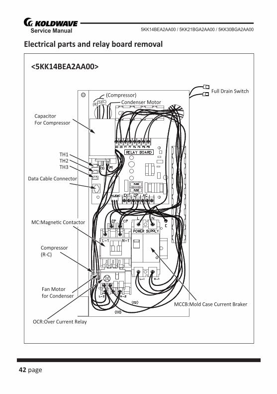
Electrical parts and relay board removal
<5KK14BEA2AA00>
MCCB:Mold Case Current Braker
OCR:Over Current Relay
Fan Motorfor Condenser
Compressor(R-C)
MC:Magne�c Contactor
Data Cable Connector
TH1
CapacitorFor Compressor
(R)
(Compressor)(S)(C) Condenser Motor
TH2TH3
Full Drain Switch
page 43
Service Manual5KK14BEA2AA00 / 5KK21BGA2AA00 / 5KK30BGA2AA00
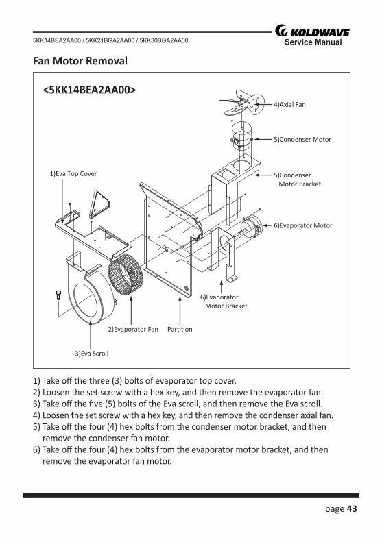
3)Eva Scroll
1)Eva Top Cover
2)Evaporator Fan Par��on
6)Evaporator Motor Bracket
5)Condenser Motor
5)Condenser Motor Bracket
4)Axial Fan
6)Evaporator Motor
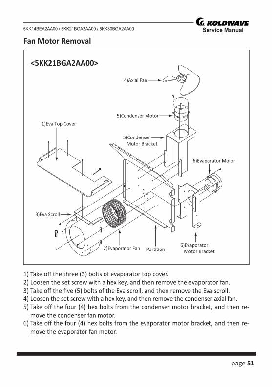
<5KK14BEA2AA00>
Fan Motor Removal
1) Take off the three (3) bolts of evaporator top cover.2) Loosen the set screw with a hex key, and then remove the evaporator fan.3) Take off the fi ve (5) bolts of the Eva scroll, and then remove the Eva scroll.4) Loosen the set screw with a hex key, and then remove the condenser axial fan.5) Take off the four (4) hex bolts from the condenser motor bracket, and then
remove the condenser fan motor.6) Take off the four (4) hex bolts from the evaporator motor bracket, and then
remove the evaporator fan motor.
44 page
Service Manual 5KK14BEA2AA00 / 5KK21BGA2AA00 / 5KK30BGA2AA00
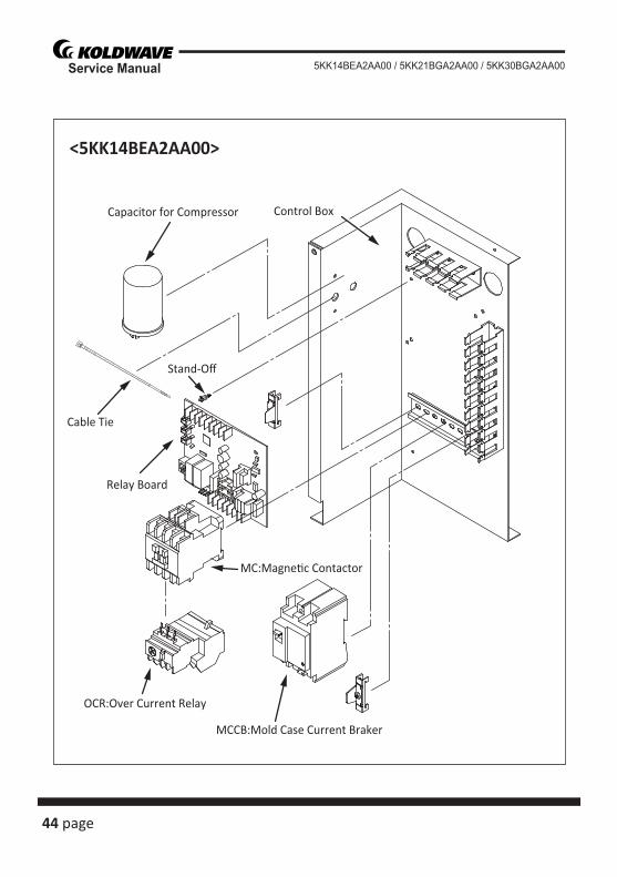
<5KK14BEA2AA00>
Control BoxCapacitor for Compressor
Cable Tie
Stand-Off
Relay Board
MC:Magne�c Contactor
OCR:Over Current Relay
MCCB:Mold Case Current Braker
page 45
Service Manual5KK14BEA2AA00 / 5KK21BGA2AA00 / 5KK30BGA2AA00
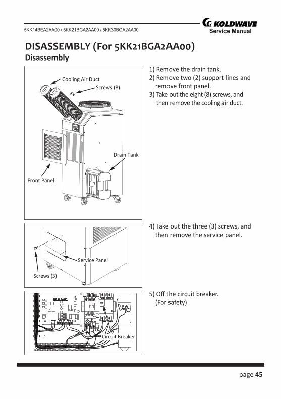
DISASSEMBLY (For 5KK21BGA2AA00)Disassembly
1) Remove the drain tank.2) Remove two (2) support lines and remove front panel.3) Take out the eight (8) screws, and
then remove the cooling air duct.
4) Take out the three (3) screws, and then remove the service panel.
5) Off the circuit breaker. (For safety)
Cooling Air DuctScrews (8)
Front Panel
Drain Tank
Screws (3)
Service Panel
Circuit Breaker
46 page
Service Manual 5KK14BEA2AA00 / 5KK21BGA2AA00 / 5KK30BGA2AA00
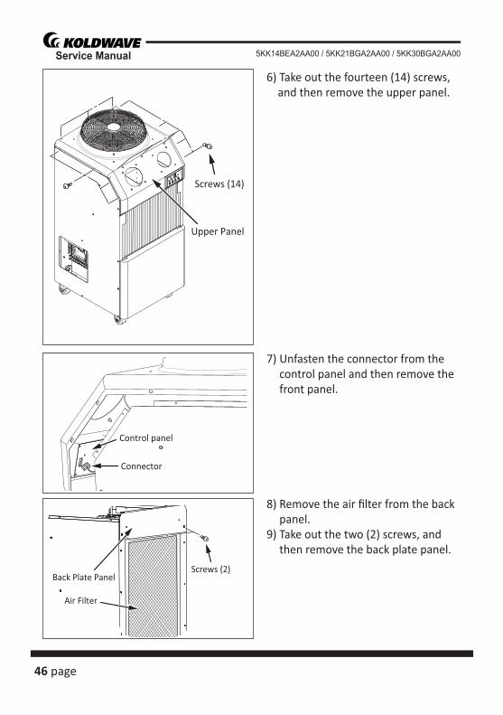
6) Take out the fourteen (14) screws, and then remove the upper panel.
7) Unfasten the connector from the control panel and then remove the front panel.
8) Remove the air fi lter from the back panel.
9) Take out the two (2) screws, and then remove the back plate panel.
Screws (14)
Upper Panel
Control panel
Connector
Screws (2)Back Plate Panel
Air Filter
page 47
Service Manual5KK14BEA2AA00 / 5KK21BGA2AA00 / 5KK30BGA2AA00
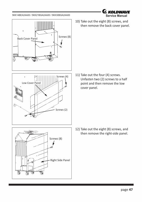
10) Take out the eight (8) screws, and then remove the back cover panel.
11) Take out the four (4) screws. Unfasten two (2) screws to a half point and then remove the low cover panel.
12) Take out the eight (8) screws, and then remove the right-side panel.
Screws (8)Back Cover Panel
Low Cover Panel
Screws (4)
Screws (2)
Screws (8)
Right Side Panel
48 page
Service Manual 5KK14BEA2AA00 / 5KK21BGA2AA00 / 5KK30BGA2AA00
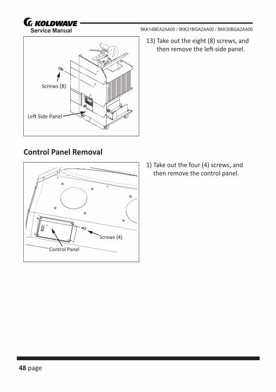
13) Take out the eight (8) screws, and then remove the le� -side panel.
1) Take out the four (4) screws, and then remove the control panel.
Screws (8)
Le� Side Panel
Screws (4)
Control Panel
Control Panel Removal
page 49
Service Manual5KK14BEA2AA00 / 5KK21BGA2AA00 / 5KK30BGA2AA00
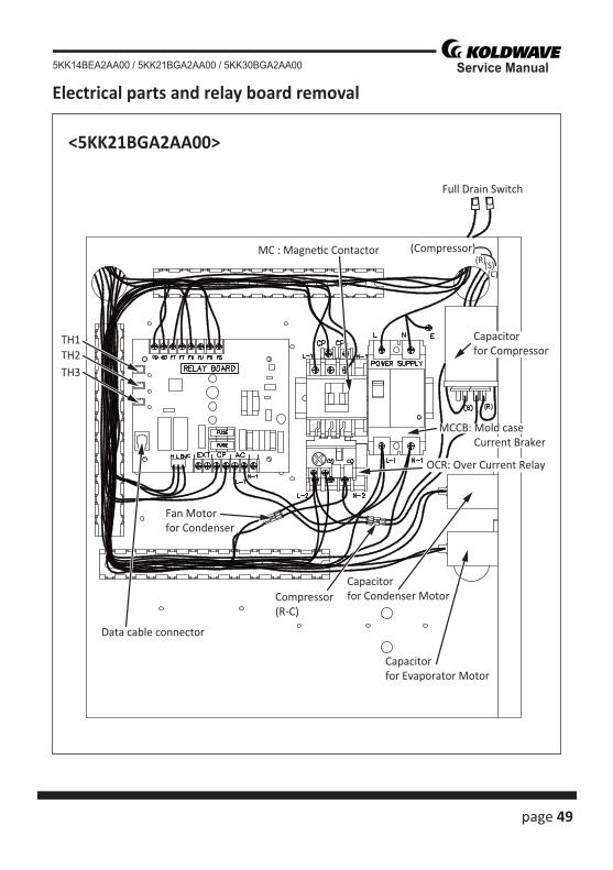
Electrical parts and relay board removal
<5KK21BGA2AA00>
MC : Magne�c Contactor
Data cable connector
Capacitorfor Evaporator Motor
Capacitorfor Condenser Motor
Fan Motorfor Condenser
Compressor(R-C)
(R)(Compressor)
(S)(C)
Full Drain Switch
TH1TH2TH3
MCCB: Mold case Current Braker
OCR: Over Current Relay
Capacitorfor Compressor
50 page
Service Manual 5KK14BEA2AA00 / 5KK21BGA2AA00 / 5KK30BGA2AA00
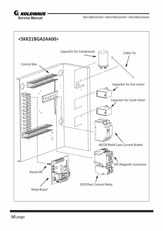
<5KK21BGA2AA00>
Control Box
Capacitor for Compressor Cable Tie
Capacitor for Eva motor
Capacitor for Cond motor
Stand-Off
Relay Board
MC:Magne�c Contactor
OCR:Over Current Relay
MCCB:Mold Case Current Braker
page 51
Service Manual5KK14BEA2AA00 / 5KK21BGA2AA00 / 5KK30BGA2AA00
3)Eva Scroll
1)Eva Top Cover
2)Evaporator Fan Par��on6)Evaporator Motor Bracket
6)Evaporator Motor
5)Condenser Motor Bracket
5)Condenser Motor
4)Axial Fan
Fan Motor Removal
<5KK21BGA2AA00>
1) Take off the three (3) bolts of evaporator top cover.2) Loosen the set screw with a hex key, and then remove the evaporator fan.3) Take off the fi ve (5) bolts of the Eva scroll, and then remove the Eva scroll.4) Loosen the set screw with a hex key, and then remove the condenser axial fan.5) Take off the four (4) hex bolts from the condenser motor bracket, and then re-
move the condenser fan motor.6) Take off the four (4) hex bolts from the evaporator motor bracket, and then re-
move the evaporator fan motor.
52 page
Service Manual 5KK14BEA2AA00 / 5KK21BGA2AA00 / 5KK30BGA2AA00
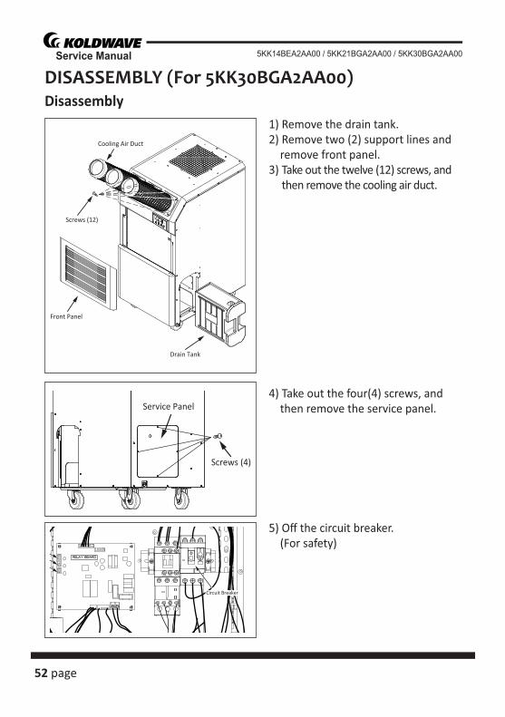
DISASSEMBLY (For 5KK30BGA2AA00)Disassembly
1) Remove the drain tank.2) Remove two (2) support lines and remove front panel.3) Take out the twelve (12) screws, and
then remove the cooling air duct.
4) Take out the four(4) screws, and then remove the service panel.
5) Off the circuit breaker. (For safety)
Cooling Air Duct
Screws (12)
Front Panel
Drain Tank
Screws (4)
Service Panel
Circuit Breaker
page 53
Service Manual5KK14BEA2AA00 / 5KK21BGA2AA00 / 5KK30BGA2AA00
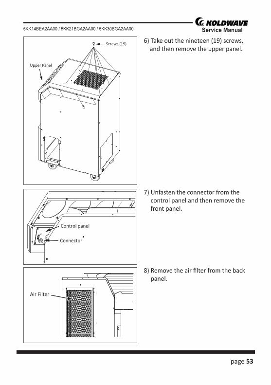
6) Take out the nineteen (19) screws, and then remove the upper panel.
7) Unfasten the connector from the control panel and then remove the front panel.
8) Remove the air fi lter from the back panel.
Screws (19)
Upper Panel
Control panel
Connector
Air Filter
54 page
Service Manual 5KK14BEA2AA00 / 5KK21BGA2AA00 / 5KK30BGA2AA00
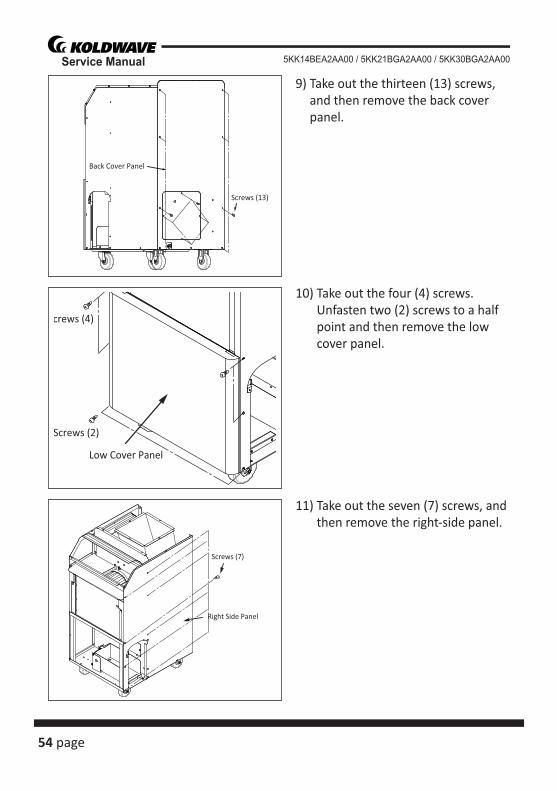
9) Take out the thirteen (13) screws, and then remove the back cover panel.
10) Take out the four (4) screws. Unfasten two (2) screws to a half point and then remove the low cover panel.
11) Take out the seven (7) screws, and then remove the right-side panel.
Screws (13)
Back Cover Panel
Low Cover Panel
crews (4)
Screws (2)
Screws (7)
Right Side Panel
page 55
Service Manual5KK14BEA2AA00 / 5KK21BGA2AA00 / 5KK30BGA2AA00
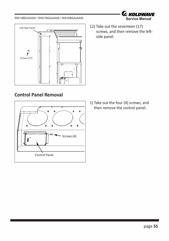
12) Take out the seventeen (17) screws, and then remove the le� -side panel.
1) Take out the four (4) screws, and then remove the control panel.
Screws (17)
Le� Side Panel
Screws (4)
Control Panel
Control Panel Removal
56 page
Service Manual 5KK14BEA2AA00 / 5KK21BGA2AA00 / 5KK30BGA2AA00
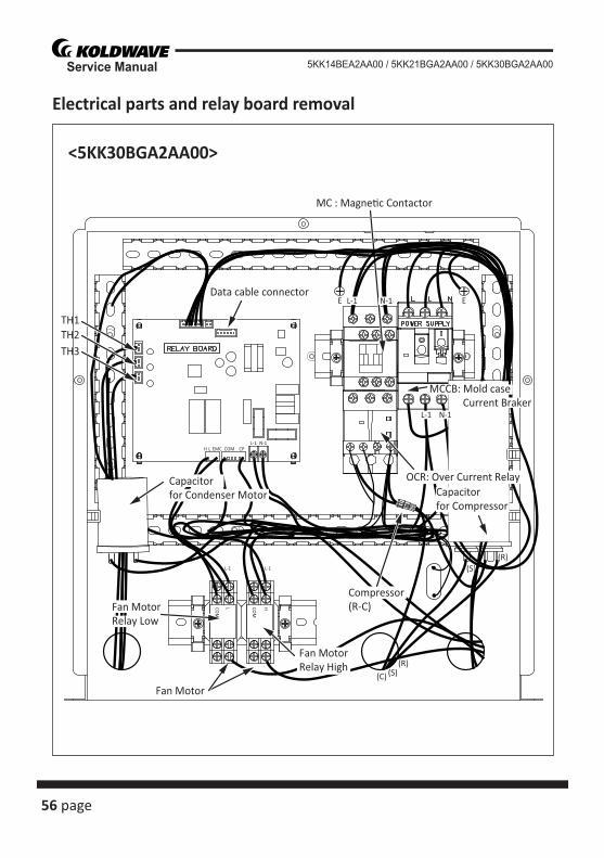
Electrical parts and relay board removal
<5KK30BGA2AA00>
MC : Magne�c Contactor
TH1TH2TH3
Data cable connector
(R)
(R)
(S)
(S)
(C)
Fan Motor
Capacitorfor Condenser Motor
N-1 EL-1
L-1
E
COMH
COM
COM
HL
L-1 L-1
L EMC CPL-1 N-1
Capacitorfor Compressor
MCCB: Mold case Current Braker
Compressor(R-C)Fan Motor
Relay Low
N-1
OCR: Over Current Relay
Fan MotorRelay High
page 57
Service Manual5KK14BEA2AA00 / 5KK21BGA2AA00 / 5KK30BGA2AA00
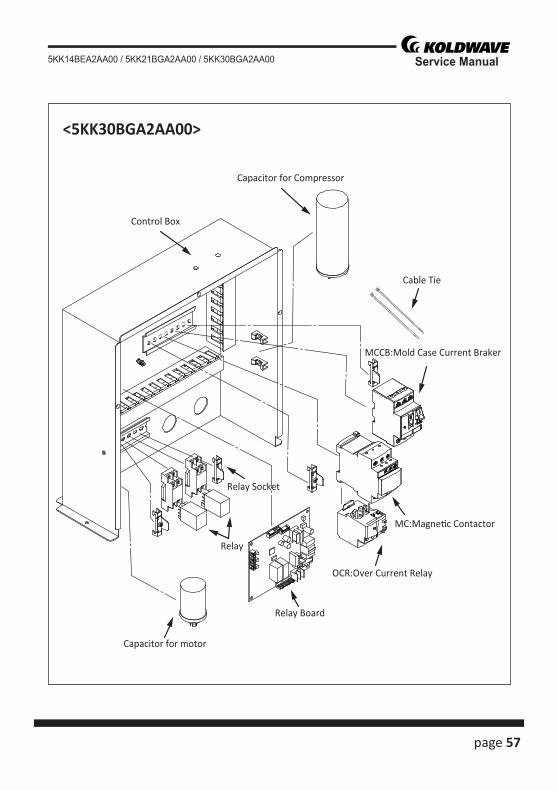
<5KK30BGA2AA00>
Control Box
Capacitor for Compressor
Cable Tie
Capacitor for motor
Relay Board
Relay
Relay Socket
MC:Magne�c Contactor
OCR:Over Current Relay
MCCB:Mold Case Current Braker
58 page
Service Manual 5KK14BEA2AA00 / 5KK21BGA2AA00 / 5KK30BGA2AA00
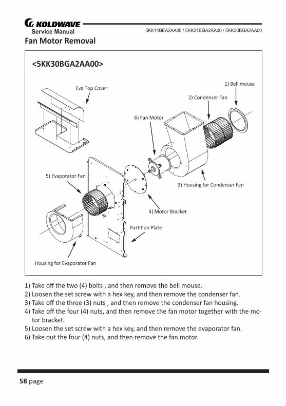
Fan Motor Removal
<5KK30BGA2AA00>
Eva Top Cover
5) Evaporator Fan
2) Condenser Fan
1) Bell mouse
6) Fan Motor
4) Motor Bracket
Par��on Plate
Housing for Evaporator Fan
3) Housing for Condenser Fan
1) Take off the two (4) bolts , and then remove the bell mouse.2) Loosen the set screw with a hex key, and then remove the condenser fan.3) Take off the three (3) nuts , and then remove the condenser fan housing.4) Take off the four (4) nuts, and then remove the fan motor together with the mo-
tor bracket.5) Loosen the set screw with a hex key, and then remove the evaporator fan.6) Take out the four (4) nuts, and then remove the fan motor.
page 59
Service Manual5KK14BEA2AA00 / 5KK21BGA2AA00 / 5KK30BGA2AA00
REFRIGERANT SYSTEM REPAIRBrazing• In the event of a leak, obstruc� on, or trouble in the refrigerant system of the unit,
replace or repair the defec� ve component. A� er replacing defec� ve component, braze all connec� ons.
1) Proper brazing techniques• When brazing, use a slightly reduced fl ame. Oxyacetylene is commonly used since
the fl ame condi� on can be easily judged and adjusted. Unlike gas welding, a sec-ondary fl ame is used for brazing. Properly preheat the base metal according to the shape, size and thermal conduc� vity of the brazed fi � ng.
• The most important point in fl ame brazing is to bring the en� re brazed fi � ng to a proper brazing temperature. Care should be taken not to cause overfl ow of the brazing fi ller metal, oxida� on of the brazing fi ller metal, or fi ller metal deteriora-� on due to overhea� ng the fl ux.
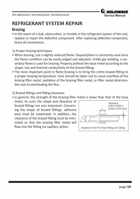
2) Brazed fi � ngs and fi � ng clearance• In general, the strength of the brazing fi ller metal is lower than that of the base
metal. As such, the shape and clearance of brazed fi � ngs are very important. Concern-ing the shape of brazed fi � ngs, adhesive area must be maximized. In addi� on, the clearance of the brazed fi � ng must be mini-mized so that the brazing fi ller metal will fl ow into the fi � ng via capillary ac� on.
Clearance
Clearance From The Pipe Fi�ng and Tubing.
0.001~0.003 in(0.025~0.075 mm)a
a
60 page
Service Manual 5KK14BEA2AA00 / 5KK21BGA2AA00 / 5KK30BGA2AA00
3) Cleaning brazing fi ller metal and piping• When the refrigerant system has been opened, exposure to heat may cause the
brazing fi ller metal to s� ck to the inside and outside of the piping. Brazing fi ller metal may also combine with oxygen in the air to form an oxide fi lm. In addi� on, grease and oils may s� ck to the pipe during handling. All these factors will reduce the eff ec� veness of brazing. Therefore, excess brazing fi ller metal must be removed with sand paper, and by thorough cleaning with a solvent such as Trichlene.
4) Dry Nitrogen gas use• During brazing, the inside of the pipe undergoes an oxida� ve reac� on due to the
brazing fl ame. Introduce dry nitrogen gas (0.3 gal/min (1 L/min); adjust with the fl ow regulator) through the pinch-off tube of the refrigerant cycle to prevent oxi-da� on.
NOTE:Do not get foreign ma� er such as dirt, water, or oil into the piping.
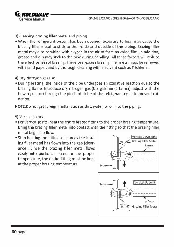
5) Ver� cal joints• For ver� cal joints, heat the en� re brazed fi � ng to the proper brazing temperature.
Bring the brazing fi ller metal into contact with the fi � ng so that the brazing fi ller metal begins to fl ow.
• Stop hea� ng the fi � ng as soon as the braz-ing fi ller metal has fl own into the gap (clear-ance). Since the brazing fi ller metal fl ows easily into por� ons heated to the proper temperature, the en� re fi � ng must be kept at the proper brazing temperature.
Burner45°
Tube
Brazing Filler MetalVer�cal Down Joint
Tube
Burner
45° Brazing Filler Metal
Ver�cal Up Joint
page 61
Service Manual5KK14BEA2AA00 / 5KK21BGA2AA00 / 5KK30BGA2AA00
WARNING
Charging the System with R-410A Refrigerant• Always ensure that the refrigerant system has been properly evacuated before
charging with the specifi ed amount of R-410A.• Equipments is only for R-410A.• Liquid charge (no gas charge).• Make sure not to use more than 90 % of the ini� al weight of R-410A in the cylin-
der.
• When handling refrigerant (R-410A), the following precau� ons should al-ways be observed:
- Always wear proper eye protec� on while handling refrigerant. - Maintain the temperature of the refrigerant container below 104 °F (40 °C). - Perform repairs in a properly ven� lated area. (Never in an enclosed environ-
ment.) - Do not expose refrigerant to an open fl ame. - Never smoke while performing repairs, especially when handling refrigerant. - Be careful the liquid refrigerant does not come in contact with the skin.• If liquid refrigerant strikes eye or skin: - Do not rub the eye or the skin. - Splash large quan� � es of cool water on the eye or the skin. - Apply clean petroleum jelly to the skin. - Go immediately to a physician or to a hospital for professional treatment
62 page
Service Manual 5KK14BEA2AA00 / 5KK21BGA2AA00 / 5KK30BGA2AA00
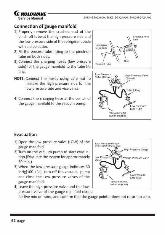
Connec� on of gauge manifold1) Properly remove the crushed end of the
pinch-off tube at the high pressure side and the low pressure side of the refrigerant cycle with a pipe cu� er.
2) Fit the process tube fi � ng to the pinch-off tube on both sides.
3) Connect the charging hoses (low pressure side) for the gauge manifold to the tube fi t-� ng.
NOTE: Connect the hoses using care not to mistake the high pressure side for the low pressure side and vice versa.
4) Connect the charging hose at the center of the gauge manifold to the vacuum pump.
Evacua� on1) Open the low pressure valve (LOW) of the
gauge manifold.2) Turn on the vacuum pump to start evacua-
� on.(Evacuate the system for approximately 30 min.)
3) When the low pressure gauge indicates 30 inHg(100 kPa), turn off the vacuum pump and close the Low pressure valves of the gauge manifold.
4) Leave the high pressure valve and the low-pressure valve of the gauge manifold closed for fi ve min or more, and confi rm that the gauge pointer does not return to zero.
High Pressure Valve(Closed)
Low PressureSide Tube
Vacuum Pump(when stopped)
Low PressureValve (Closed)
Tube Fitting
Pinch-Off TubeSeal
Charging HoseSide
RefrigerantCycle Side
Low PressureSide Tube
Vacuum Pump(when stopped)
30 inHg (100 kPa) or larger
High Pressure Valve
High Pressure Gauge
Low Pressure Gauge
Low PressureValve
page 63
Service Manual5KK14BEA2AA00 / 5KK21BGA2AA00 / 5KK30BGA2AA00
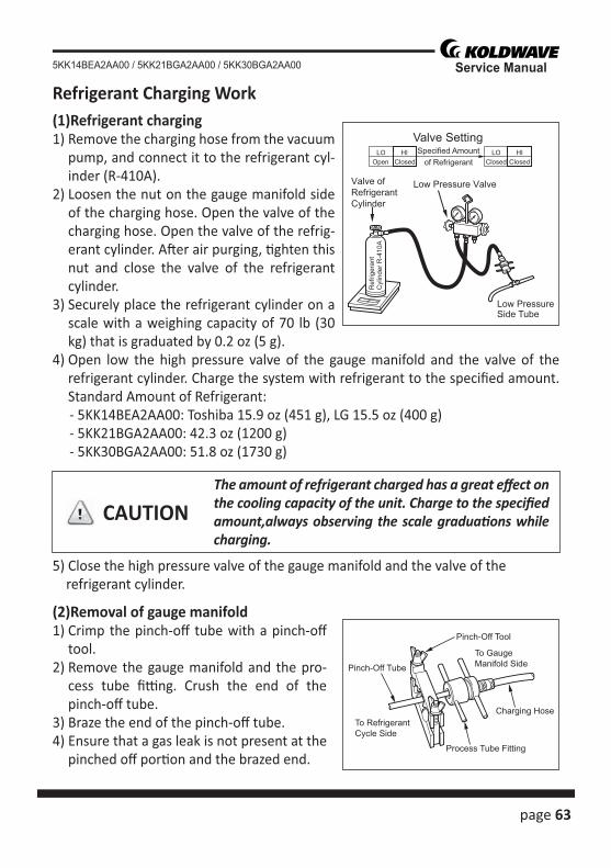
Refrigerant Charging Work(1)Refrigerant charging1) Remove the charging hose from the vacuum
pump, and connect it to the refrigerant cyl-inder (R-410A).
2) Loosen the nut on the gauge manifold side of the charging hose. Open the valve of the charging hose. Open the valve of the refrig-erant cylinder. A� er air purging, � ghten this nut and close the valve of the refrigerant cylinder.
3) Securely place the refrigerant cylinder on a scale with a weighing capacity of 70 lb (30 kg) that is graduated by 0.2 oz (5 g).
4) Open low the high pressure valve of the gauge manifold and the valve of the refrigerant cylinder. Charge the system with refrigerant to the specifi ed amount.Standard Amount of Refrigerant:
- 5KK14BEA2AA00: Toshiba 15.9 oz (451 g), LG 15.5 oz (400 g) - 5KK21BGA2AA00: 42.3 oz (1200 g) - 5KK30BGA2AA00: 51.8 oz (1730 g)
5) Close the high pressure valve of the gauge manifold and the valve of the refrigerant cylinder.
(2)Removal of gauge manifold 1) Crimp the pinch-off tube with a pinch-off
tool.2) Remove the gauge manifold and the pro-
cess tube fi � ng. Crush the end of the pinch-off tube.
3) Braze the end of the pinch-off tube.4) Ensure that a gas leak is not present at the
pinched off por� on and the brazed end.
CAUTIONThe amount of refrigerant charged has a great eff ect on the cooling capacity of the unit. Charge to the specifi ed amount,always observing the scale gradua� ons while charging.
Ref
riger
ant
Cyl
inde
r R-4
10A
Low PressureSide Tube
Low Pressure ValveValve ofRefrigerantCylinder
LOClosed
HIOpen
LOClosed
HIClosed
Valve SettingSpecified Amount
of Refrigerant
Pinch-Off Tube
Pinch-Off Tool
Process Tube Fitting
Charging Hose
To Gauge Manifold Side
To Refrigerant Cycle Side
64 page
Service Manual 5KK14BEA2AA00 / 5KK21BGA2AA00 / 5KK30BGA2AA00
•Do not a� empt any repair on a charged system.
• Before checking for gas leaks, fully confi rm that there is nothing fl ammable in the area to cause an explosion or fi re. Contact of refrigerant with an open fi re generates toxic gas.
WARNING
WARNING