Embed Size (px)
Citation preview
Kinematic Decoupling in Mechanisms and Application to a Passive Hand Controller Design Vincent Hayward, Chafye Nemri, Xianze Chen, and Bertrand Duplat’ Mc Gill University Research Center for Intelligent Machines 3480 University Street Montreal, Quebec H3A 2A7, Canada
Received March 2, 1992; accepted August 8, 1992
Observations regarding the kinematics of mechanisms are applied to the synthesis of a passive hand controller. It is argued that stiffness (and damping) properties are central to the effectiveness of such devices and in particular that the simplicity of these proper- ties is crucial. What simple means is analyzed and it is shown that only certain types of manipulators can appropriately be used. In effect, decoupling is shown to be architec- ture and configuration dependent. The properties of parallel mechanisms are reviewed and found appropriate for restricted-workspace hand controllers. A particular kinematic design is then derived and a practical implementation described. 0 1993 John Wiley & Sons, Inc.
1. INTRODUCTION
In this article we apply observations regarding the kinematic properties of mechanisms to the design of a simple yet effective hand-held mechanism in- tended to be used as an input device. Such a device can be used in particular for the remote control of a slave robotic manipulator, in computer graphics appli- cations, and other such cases. Because of its function, it will hereafter be called a “hand controller.”
*On leave from Electricit6 de France, Paris.
Journal of Robotic Systems 10(5), 767-790 (1993). 0 1993 by John W h y & Sons, Inc. CCC 0741 -2223/93/050767-024

768 Journal of Robotic Systems-1 993
Hand controllers can be active or passive. They can also be designed to provide a large workspace or a restricted range of motion. The combination of these properties form four broad categories that are now briefly discussed to specify the intended use of the described device.
A central function of active hand controllers is to provide feedback to the operator by applying forces and torques to her or his hand. They are conse- quently actuated mechanisms. Achieving adequate performance leads to many challenging design problems that are the subject to much research.14 In con- trast, passive hand controllers do not produce any mechanical energy but can only store it in springs or dissipate it through damping and friction. Thus, they necessarily act as unidirectional information transducers from an operator to a machine .
One central function of large-workspace hand controllers is to measure the position to which the operator moves them. Thus, a primary design require- ment is to allow the operator to use the hand controller comfortably. Large- workspace hand controllers are designed to provide sufficient workspace to allow the control of a task through geometric correspondence. A most familiar example is that of a “mouse” device commonly attached to computer worksta- tions: The motion of the screen cursor reflects geometrically that of the mouse. In robotic applications, hand controllers with five or six degrees of freedom (dof) usable inside a large workspace compatible with that of the human arm are required. Hand controllers that also have the possibility to impart force back to operators are normally called “master manipulator arms.” It is called master because another manipulator can be slaved to it, resulting in a bilaterally coupled system (see ref. 4 for more details). Some of these large-motion hand controllers are exact or approximate kinematic replica of the manipulator slaved to them. Others, the so-called “universal hand controllers,” have a kinematic structure that may result solely from performance requirements without a priori regard to the details of the system slaved to Digital com- puters then are used to carry out the necessary coordinate transformations. Additional discussion on this topic would fall outside the scope of this succinct classification.
Other hand controllers have restricted workspaces. The signals produced by the controller’s small displacements are mapped into velocities of the slave system being controlled. Thus, provided enough time, arbitrarily large motions of the slave manipulator can be controlled. The great majority of these control- lers are passive. The sophistication of such hand controllers can vary from a simple on/off push button (for example, an electric window in a car) to the measurement of the six components of the displacement of a handle.
Restricted displacement hand controllers that are also capable of reflecting forces have seldom been used in teleoperation, although they are fairly com- mon in some other contexts such as advanced aircraft control. A discussion of the reasons for this would also fall outside the scope of this article.
Provided adequate information returns from the task, most commonly via the vision channel and more rarely through audition, it has been observed that

Hayward et al.: Passive Hand Controller 769
passive hand controllers provide effective means to perform teleoperation, although force feedback has often been demonstrated to enhance teleoperation. Nevertheless, there exist many situations in which force feedback is impracti- cal or simply not wanted. Because of their simplicity, passive hand controllers are used in many applications and occupy a sizeable functional niche. In fact, passive hand controllers are routinely used in undersea operations, space (the only type used so far), and a variety of other applications such as earth-moving equipment, remote control of vehicles and drones, or displacement of cursors on computer screens.
2. FUNCTION AND DESIGN GOALS
We now turn our attention to the design of a passive, restricted displacement hand controller that is appropriate for workstation situations. As outlined above, the mechanical function of the hand controller is to undergo small motions resulting from the forces applied by an operator’s hand. Because of the restricted displacements, the intent is to use this device in rate mode; in other words, its measured displacements are mapped into velocities of the controlled object.
The human kinesthetic perception obtains cues from a variety of mechano- receptors distributed throughout the structure of the system (joints, muscles, tendons, skin). Using these cues, a subject experiences the simultaneous sensa- tion of position of, and forces applied to, an object held in the hand.6 It is generally accepted that a stable representation in the central nervous system of the motion of a held object results from a combination of several channels, in particular position and force. In teleoperation, vision will also be involved through the observation of the resulting task. We hypothesize that a general- purpose hand controller should attempt to maximize the use of all of the kines- thetic cues. The justification for this is discussed next.
In a quasistatic equilibrium, barring gravity, and considering that biomechan- ical friction forces are exceedingly low, the only forces counteracting those produced by the hand controller moved away from its free equilibrium position are those arising from the muscles of the operator of which she or he is keenly aware through many channels (possibly muscle spindles, Golgi tendon organs, and skin pressure receptors: SA I and SA 11).
If the device is made very stiff, forces generated by the muscular system of the operator will mostly result in elastic deformations of the various tissues forming the upper extremity of the operator. These deformations may also significantly involve any supporting structure: the operator’s body, the chair, etc. At the other extreme, if the hand controller is made perfectly compliant, or in other terms has zero stiffness, in the quasistatic case no other external forces will be felt by the operator other than those resulting from gravity forces.
It can be easily appreciated that the two extreme cases just outlined fail to exploit the full potential of the human perception system. In the case of infinite stiffness, no displacement results from the action of the operator other than

770 Journal of Robotic Systems-1 993
deformations of her or his own tissues. In the case of zero stiffness, no sensa- tion of force informing about the motion of the hand controller is received. It can therefore be supposed that an improved sensation of motion will result from a design between these two extreme cases.
If the device is to have some finite stiffness, forces applied to it will result in displacements. This relationship can be expressed as a mapping that is linear for infinitesimal motions and in the absence of significant friction: w, = Fx, where F is a square matrix with 36 entries (to be discussed in greater details in the next section). An operator can be expected to learn some of this mapping, thus internally constructing a set of constraints between sensed forces and displacements. The simpler this mapping is, the more successfid the learning will be and, consequently, the more effective use of these conetraints can be made by the operator.
Notice that if the device is given viscious friction properties the same reason- ing applies. In effect, the human kinesthetic system is capable of perceiving velocities. The establishment of a relationship between force and velocity, wv = Bv, can also be hypothesized to improve the perception of motion for some well-chosen damping matrix B. The prototype described later in this article does not have dampers, but these are planned for a later version.
To summarize, in the case of a passive hand controller having a simple stiffness-and possibly damping-properties the position and force sensations are related in a simple fashion that provides supplemental and consistent sen- sory feedback to the operator. In effect, this is a case of sensory syncretism that naturally lends itself to utilization. The stiffness (respectively viscous) behavior of a mechanism is thus central to the design of a passive hand control- ler. This will be discussed in greater detail in the following section.
Next comes the question of realizing desired properties by means of a me- chanical device. We could, of course, think of cutting or forming a piece of material yielding the required stiffness. This is the approach normally adopted in manufacturing force-torque sensors. It has also been carried out by Hirzinger to implement a hand controller.’ The cited design also proposes an optical solution for sensing the displacements of the handle. Another alternative for realizing a given stiffness is the use of linkages forming a spatial mechanism, some of the joints of the said mechanism being fitted with individual return springs, possibly dampers, and position sensors. It is later argued in this article that this approach can lead to effective designs, allowing greater freedom for their implementation. In particular, mechanisms with parallel linkages are found to be most appropriate for such a purpose. The issues discussed in the rest of this article must also be put in relation with the development of Remote Center of Compliance (RCC) devices, which exploit well-chosen stiffness prop- erties to accomplish high-speed assembly tasks.8
The questions that can now be addressed are: How can stiffness properties be characterized and how can these be obtained from a mechanism in general and a parallel mechanism in particular? Other questions related to implementa- tion techniques will only be briefly discussed.

Hayward et at.: Passive Hand Controller 771
3. STIFFNESS AND DAMPING OF MECHANISMS
3.1. Stiffness and Damping Matrices
First, consider arbitrary spatial mechanisms made of lower pairs. The rela- tive position of each lower pair is defined by one scalar variable, a “joint parameter.” We then consider those spatial mechanisms that have a configura- tion unambiguously defined by six joint parameters. These six scalar parame- ters form the input space. Because our analysis is local, we will be content with defining this input space as the neighborhood of a point in (R6).
The output space of the mechanism is the position in space of a selected link. It can be specified in a number of ways. A twist, a set of three infinitesimal displacements and three infinitesmal rotations, describes compactly the instan- taneous motion of a rigid body. A wrench, a set of three forces and three moments, describes the forces applied to a rigid body. Twists and wrenches are instances of general screws made of one line vector and one free vector. Screws are origin dependent and the vector of coordinates representation of a screw depends on a reference frame. It is well known that following the princi- ple of virtual works infinitesimal changes of joint parameters are related to the twist of the output link in a manner that is formally analogous to the relation- ship between joint forces and external wrenches (quasistatic equilibrium). Let J be the Jacobian matrix of the kinematic map from output link displacements to joint changes:
p = J x
w = J T h (2)
where p is the vector of joint parameters changes, x is the twist vector output link displacements, w is the external wrench applied to the output link, and h is vector of joints forces and torques. We are interested in the stiffness behavior of the device as seen from the output link. By construction, the contribution of the springs to joint forces is
h , = K p (3)
with K diagonal. In an analogous way to Salisbury’s approach to designing an algorithm for the control of a robot manipulator ~tiffness,~ we substitute for h, and p in (2) and (3):
w , = J T K J x (4)
By definition
w, = F x ( 5 )

772 Journal of Robotic Systems-1 993
where F is the stiffness matrix of the mechanism. From eqs. (4) and (3, we conclude that
F = J T K J (6)
If we wish to include the contribution of viscous friction to the forces acting at each joint, h = h, + h, = Kp + Br, where r is the vector of joint rates, an analogous substitution will lead to defining
V = J T B J (7)
as the mechanism damping matrix. Thus, the external wrench that balances elastic and viscous forces can be written:
w = J T K J x + J I B J v (8)
Keep in mind that the foregoing discussion applies perfectly to the case where the return springs and dampers are replaced by actuators, sensors, and a con- trol algorithm. Then, we would have the possibility to program the stiffness and damping matrices of a mechanism within the limits that are about to be dis- cussed, and at the expense of greater system complexity.
As a final remark in this section, we wish to point out that, more generally, every comment in the rest of this article regarding kinematic analysis and kinematic design of mechanisms may have impact on control law design be- cause the kinematics may be viewed as the “transfer function” between actua- tor effort and forces expressed in output link coordinates.
3.2. Decoupling
We may first observe, as did Xu and Paul,l0 that if all the joints have the same stiffness and the same damping, and if the product JTJ is a diagonal matrix, then the matrices F and V are also diagonal matrices proportional to JTJ. However, this decoupling property requires a more precise definition in associ- ation with a physical interpretation. This is done next in the sole case of the stiffness matrix because the results are completely analogous in the case of the damping matrix replacing infinitesimal displacements by velocities. We first rewrite the stiffness matrix in block form:
Decoupling occurs when F12 = F & = 0 . Because F is symmetric, F I I and FZ2 are symmetric too and can be factored into
Hayward et al.: Passive Hand Controller 773
Thus
The property of stiffness decoupling can now be better discussed. Isotropic decoupling means that external forces applied at a given point of
the output link cause pure translations of that link. Likewise, external moments generate pure rotations about a line passing by the same point. In addition, this relationship is the same in all directions. The stiffness matrix is then a diagonal matrix of the form F = diag[ul, UI, UI, u2, u2, UZ], and At and A2 in (10) are proportional to unit matrices. For a given architecture, it may be impossible to realize this type of decoupling by changing the design parameters. Neverthe- less, it is possible to imagine mechanisms that could be made to have this property readily: a gimbal supported by three serial prismatic joints arranged in orthogonal directions, for example. However, such serial mechanisms will not be considered for our purpose. Examples of obvious decoupling are more diffi- cult to exhibit in the parallel case.
General decoupling does not require isotropy: In the stiffness matrix (lo), QI and Q2 are equal and F has the form F = diag[ul, ~ 2 . 4 , u4, us, u61, ui f uj, i f j . Equation (10) assumes the form
A pure external force evokes only a translation, but in a direction that diverges from that of the force. Likewise, a pure external moment evokes only a rotation but around a direction that diverges from that of the external moment. There are three orthogonal directions in the space in which the said directions will coincide. When Q is a unit matrix, these three directions are aligned with the coordinate axes. So, actually, forces and moments may be decoupled but the device behaves anisotropically .
Partial decoupling means that a mechanism is decoupled between forces and moments, but forces are coupled together and so are the moments. Decoupling occurs among forces along three orthogonal directions in space and among moments around three other directions. Partial decoupling corresponds to a block diagonal stiffness matrix as in eq. (lo), where QI is different from Q2.
In summary, the three types of decouplings lead to decoupling between forces and moments. However, for isotropic decoupling forces and moments are decoupled among themselves and independently from the directions of action. For general decoupling, decoupling occurs also among forces and among moments only in three orthogonal directions in space. As a special case, these three directions can coincide with coordinate axes. For partial decou- pling, decoupling among forces and among moments cannot occur simulta- neously.

774 Journal of Robotic Systems-1 993
The expression of the stiffness matrix, F = J T K J , is related to the Jacobian matrix. Because the value of the Jacobian matrix varies with the configuration, decoupling can occur only locally at particular locations.
It must be noticed that in case of general decoupling the orientation of the reference frame must be selected for the stiffness matrix to take a diagonal form, whereas in the case of isotropic decoupling this orientation can be arbi- trary and the stiffness matrix will always assume a diagonal form. In the case of partial decoupling, we will naturally select a reference frame aligned with the directions in which decoupling occurs for forces, or for moments, leading to simpler expressions. This fact follows from the transformation of twists and wrenches in rotated reference frames. So, in the following we will assume the reference to be selected so that the stiffness matrix assumes the simplest form.
It could be thought that for an arbitrary mechanism it is possible to decouple the stiffness matrix by means of some systematic method, such as relocating the wrench acting point or altering the stiffness parameters of the springs, without changing the architecture and configuration. Unfortunately, it can be shown that decoupling is architecture and configuration dependent.
3.2.1. Effects of Moving the Acting Point
Stiffness depends on the acting point of an external force (possibly resulting from a system of forces). Let xo be a displacement twist and wo be a wrench acting at point 0, the origin. We now move the external wrench to act at point P. As seen from point P, the stiffness will be changed as the motion resulting from the translated system of forces will be changed. Let s denote the vector from point 0 to point P.
To obtain the stiffness at point P as a function of the stiffness at point 0, we simply express in frame 6 the twist measured at P and express in frame 6 the wrench applied at P. Let S = the skew symmetric matrix formed from vector s.
x o = [3 = [ p p - ; ” ” ] = [ o I S I ] [;;I = s x p (12)
fP I 0 wo = [to] = [ fp + mp] = [ I ] [ f p ] = S - T W P (13)
Substituting (12) and (13) into (4) yields
S - T wP = J ; K J~ s X,
Multiplying by ST on both sides of the above, we obtain
= [Jo SIT K [Jo S] x p

Hayward et al.: Passive Hand Controller 775
By definition
where J p denotes the Jacobian matrix in frame 9 originating at point P. Thus, two relationships are obtained:
The stiffness matrix at point P can be written in block form:
An arbitrary mechanism with undecoupled stiffness matrix cannot be made partially decoupled by moving the external wrench acting point because the two block matrices Fp12 and Fpzl (Fp12 = F L I ) cannot be simultaneously null matrices. For a partially decoupled mechanism, changing the point of action of the external wrench will lead to the following stiffness matrix:
The condition Fo1i.S = STF&, = 0 defines the location of the output link where the mechanism has partial decoupling. Moving from that point will destroy that property. For a generaIly decoupled or isotropically decoupled mechanism, the stiffness matrix for an arbitrary point (DI and D2 diagonal) is
Because D I S and STDl are zero only if s is zero, decoupling can occur at only one point.

776 Journal of Robotic Systems-1993
In summary, for a mechanism that is partially decoupled, generally decou- pled, or isotropically decoupled it will have these properties at only one point. Conversely, for an undecoupled mechanism it is impossible to decouple it by moving the point of action of the external wrench without changing the archi- tecture and configuration.
Equations (16) and (17) allow us to compute the Jacobian and stiffness matrices at any point.
3.2.2. Effects of Altering the Spring Constants
From the definition of the stiffness matrix F = J W J , another possible method for designing a mechanism such that the stiffness matrix to be diagonal is to alter the parameters in K, i.e., the stiffness of the return springs.
LetJj,jij, and kij be the elements of F, J , and K respectively. The element of F can be expressed as
leading to 36 equations. F is a symmetric matrix; to make it partially decoupled, nine elements of the off-diagonal block matrices must be zero. Nine equations are obtained:
6
k,jnijN = 0 i, j # n n = l
in which six independent parameters kn can be altered. Thus, there is no solu- tion in general. That means that selecting spring constants can only partially contribute to making the stiffness of a mechanism with return springs de- coupled.
3.2.3. Discussion
From moving the action point and altering the spring parameters, nine inde- pendent parameters can be selected. To make the stiffness partially decoupled, nine elements are required to be zero. Therefore, the possibility exists that this can be achieved for any arbitrary mechanism. In practice, the procedure can be complicated because it depends on the expression of the Jacobian matrix. To make the stiffness matrix generally decoupled, 15 nondiagonal elements in the stiffness matrix must be zero, which cannot be achieved in general. However, for special cases the methods mentioned can contribute to the goal and must be considered in a design procedure.
Thus, the property of stiffness decoupling of a mechanism is architecture and configuration dependent and cannot be achieved in general by changing the acting point of the external wrench and altering the spring parameters.
Hayward et al.: Passive Hand Controller 777
As an example, in the design of the hand controller described in this article, we will be satisfied with a special case of general decoupling leading to a stiffness matrix of the form F = diag[ul, ul, u2, u3, u3, 4 1 , this occurring for a particular set of spring constants and point of action of the external wrench. This has been obtained empirically from consideration of geometric symme- tries. Systematic methods for the design of architectures that lead to stiffness decoupling are left to future studies.
4. DESIGN OF THE HAND CONTROLLER
Before we expose the particulars of the geometric design of the proposed mechanism as well as practical implementations, a short discussion regarding the appropriateness of parallel mechanisms is carried out.
4.1. Properties of Parallel Mechanisms
labeled as follows: Parallel mechanisms have, in general, properties that can be summarized and
Property S. The foremost of these properties is that they can achieve high structural stiffness because they include closed kinematic chains.
Property L. As a consequence of property S, low inertia can be easily achieved, especially if the design strives to keep the mechanism as close as possible from a truss structure in which no structural member is stressed other than in compression or in tension.
Property I . In general, they display well-behaved inertial properties. Unlike serial manipulators, any motion of the end effector involves motions of all the links, thus inducing an averaging effect over the inertial forces appear- ing in each submechanism.
Property A. Instrumented parallel mechanisms can be made accurate because sensing errors do not accumulate but instead average. In addition, most parallel structures do not require long-lever arms, which decrease the accuracy of position measurements by means of rotary sensors. The same remarks hold for the backlash effects.
Property W. Parallel mechanisms tend to have small workspaces. This is due to two factors. First, there is an increased possibility for interference between links and trusses as the mechanism moves. This is usually difficult to avoid by design. Second, because there are combinatorially many kine- matic chains in a parallel mechanism (in particular, a spatial one), the portions of workspace free of singularities tend to shrink. As an aside, please see ref. 11 for possible remedies.
We now turn our attention to the desirable requirements for an input device:
Simplicity and robustness. This requirement is partially addressed thanks to the structural properties of parallel mechanisms (property S ) . Although

778 Journal of Robotic Systems-1993
parallel mechanisms tend to have many moving parts (often gimbals or spherical joints are required), many of these parts and subassemblies can be made identical. In addition, they are readily available from design cata- logues. Also, because of the accuracy of these designs (property A) low part tolerances may be used, which is important from a manufacturing viewpoint.
Structural stiffness. This is important because sensors should measure the motions of the mechanism and not its structural deformations. Because high stiffness can be easily achieved, in particular if any bending and twisting moments are avoided in the structure, ordinary materials and construction gives good results (property S).
Accuracy. The mechanism needs to be accurate. In the present application, absolute precision is not important; however, resolution is crucial. Aside from structural deformations, the precision depends on sensors' intrinsic precision, kinematic amplification, and backlash in the joints.
Weight and inertia. Because the device is hand held, low inertia is essential (property S). In addition, inertia should not vary steeply with the position
Smoothness and low friction. The initial design rationale is to construct a simple mapping between displacements and forces. The human motor sys- tem excels at dealing with friction as it is a requirement for everyday life. From our experience, a small amount of solid friction does not adversely affect hand motion comfort or accuracy. Small amounts may, in fact, be beneficial to reduce small-magnitude tremor. However, obviously, friction should not undergo abrupt changes in magnitude. The kinematic properties of parallel mechanisms contribute to achieving this requirement, due again to the averaging effect of joint motions.
In conclusion, it was tempting to consider the construction of an input device
(property I).
using a parallel structure.
4.2. Kinematlc Design
4.2.1. Theory
Among many possibilities, the widely studied Stewart mechanism, because of its regularity, was an attractive starting point. We mentioned earlier that looking for symmetries was a strategy for eliminating extraneous constraints. It can be observed that the mechanisms with triangular platforms form an octahe- dron and that their motion can be analyzed in terms of its deformations, which was done a century ago by Bricard.'* The decoupled case about to be derived is in fact close to a regular octahedron.
A fully parallel manipulator is characterized by a base plate and a movable plate connected with six sliding legs. There are 36 independent parameters in the design of this kind of mechanism because each leg has two ends and each end has three independent coordinates. These parameters, plus the spring con- stants, lead to a total of 42 design parameters. This, in principle, should allow

Hayward et al.: Passive Hand Controller 779
b2
Figre 1. Geometrical design parameters.
us to design any stiffness matrix we would want. The systematic solution to this problem was not attempted, but a particular solution will be exhibited.
A first simplification is to consider that the attachment points of the legs belong to two planes. Also, seeking decoupling, a symmetry under a set of discrete rotations leads to chose the platforms as hexagons with two alternating edge lengths. In selecting the design parameters, we use a method similar to that proposed by Ma and Angeles although they used this approach in the context of a different problem.” In a symmetrical arrangement, only five pa- rameters need to be selected: a ] , a2, b l , b2, and h. The mechanism is arranged as shown in Figure I in its neutral position at the center of its workspace away from singularities. The six legs have the same lengths I,. The distance between the two platforms is h.
Plucker coordinates can be used to write the Jacobian matrix by inspection of the geometry. We simply compile line by line the instantaneous change in leg length:
where the ris are vectors radiating from the center of the movable platform to each end of the legs and the qis are the directions of each leg:
l j = /Mi - BiJ (20)
The expression of the matrix is as follows:

780 Journal of Robotic Systems-1993
If the spring constants are all the same, K = kl, then
where
It can be seen that if we select parameters to set c5 = 0 the stiffness matrix will be diagonal, although not necessarily isotropic. Solving eq. (28) for c5 = 0 is zero yields

Hayward et al.: Passive Hand Controller 781
as a necessary and sufficient condition for the symmetrical design to have general decoupling. From this equation, we can find an infinite number of combinations of at, a2, b , , and b2.
Further study reveals that the elements of the stiffness matrix cannot be selected arbitrarily. For that to be possible, we would need additional geomet- ric parameters (five were used). That means we need to change the architecture and configuration and possibly choose different spring constants and select a different point of action.
4.2.2. Practice
Setting al = a2 = bl = b2 to satisfy condition (29) leads to an unreasonable choice because the platform is singular when the legs have the same length and extremely ill-conditioned otherwise.
We then notice that the decoupling property is independent of the choice of h. In other words, changes in the “aspect ratio” of the structure leaves the decoupling property invariant. Referring to Figure 1, it can be intuitively ob- served that changing h modifies the kinematic properties in a well-defined pattern. A slender design creates a large kinematic gain around the Z-axis: small joint changes corresponding to large swiveling motions; with a corre- sponding kinematic gain approaching one for motions along the Z-axis; while reciprocal properties occur along and around the X- and Y-axes. A flat design will have just the opposite effect.
It could be thought from the observations in the two previous paragraphs that better conditioning might occur for a design that would have two identical triangular platforms, at = b2 = 0 and a2 = bl, and some good choice for h. It can, however, be verified that condition (29) cannot hold in that case. Observ- ing now that the condition is trivially verified for at = b2 = 0 and a2 = 2bt, this solution is attempted. As can immediately be seen, the fixed platform is twice the size of the top platform, yielding a feature that in itself is not practical. Further, evaluating the stiffness matrix for a particular instance of the leg’s lengths we find that it takes the following form: ct = c2 = 0.5; c3 = 4.8; c4 = cs = 0.009; c6 = 0.004, with c;, i = 1,3 dimensionless and c;, i = 4, 6 in m2 rad-’, all these numbers multiplied by the leg’s spring constants, which are in Nm-’. This design has to be discarded because it results in too low angular stiffness in addition to an awkward configuration.
A search by trial and error, taking into account the scale of the device to provide space to lodge the operator’s hand and comfortable stiffness constants, led to the following choice of parameters: h = 0.225 m, at = b2 = 0.015 m, a2 = bt = 0.215 m, and k = 423 Nm-’, leading to a matrix of the form: cI = c2 = 0.6; c3 = 4.8; c4 = c5 = 0.038; c6 = 0.0152. The matrix is not perfectly decoupled as the four c5 coefficients only approach zero; cs = 0.068 m rad-’.
It must be recalled that because the Jacobian J changes as the mobile plat- form is moved the stiffness matrix changes too. To quantify the effectiveness of

782 Journal of Robotic Systems-1993
0 8 E 0
8 0
3 0 -
h -u
8 $9 ?
0 8 E- 0
0
3 0 -
h =
8 4
8 0 E 0

0.05
1
-5 -10
-5
0 5
10
Ang
le ab
out X
(Dee
) A
ngk
abou
t X (D
eg)
-5 ~IxI
-10
-5
0 5
10
Ang
k ab
out Y
(Dee)
::.y
--y
- I 0.03
-0.0
4
LL
-10
-5
0 5
10
Ang
le ab
out Y (D
ee)
~o
*m
~~
;o
.05rl
$0
io
B E
4.05
-10
-5
0 5
10
Ang
k ab
out 2 (D
cg)
4.05
-10
-5
0 5
10
Ang
k ab
out Z
@cg
)
0.06
1 1
Ang
k ab
out X
(Dee
)
1! O5
P
01
0 *D
-5
0
5 10
Ang
k ab
out Z
We)
Figure 2
. (b
) Plo
t of
the
var
ious
coup
ling
effe
cts.

784 Journal of Robotic Sysrems-1993
the decoupling effect, plots were made to display the cross-coupling for appre- ciably large motions of the platform. Inspection of Figure 2 shows that the worst case occurs in the coupling between translations along the X- (respec- tively Y-) axis and moments around the Y- (respectively X-) axis, as well as between rotations around the X- (respectively Y-) axis and forces along the Y- (respectively X-) axis. Plots are shown in Figure 3 to help appreciate the rela- tive importance of these effects. As can be seen, although the stiffness proper- ties along and around the principal directions remain fairly constant for large excursions of the platform (slope of the curves) decoupling degrades rapidly because, for example, in the worst case, a 5-cm translation excursion of the platform the the X direction creates a torque around the Y direction equivalent to a rotation about the same axis by 5”. However, from experience we have noticed that the operator learns, rather quickly, how to compensate for the translation to torque coupling. Thus, from a practical point of view, we achieved a design that has the desired stiffness characteristics.
5. PRACTICAL REALIZATION AND RESULTS
5.1. First Prototype
A first prototype was constructed by the authors. It was built out of simple materials and mechanical components. Sliding joints are made of precision steel shafts sliding in bronze bushings. Small ball bearings were used to decou- ple the rotary motion of the shafts from the position sensors. High-resolution linear potentiometers were used as position sensors. Although it is a rather simple construction, a great deal of accuracy, as well as a smooth feel, was easily achieved.
A clear feeling of the neutral position was first thought to be essential for this type of device. This has been implemented using antagonists springs with over- lapping mechanical stops that keep them slightly preloaded around the neutral position, thus creating a small dead-band in their response (see Fig. 4). This dead-band has been made small enough not to perturb the decoupled behavior and yet to be clearly felt by the operator. Although the results of this strategy were quite acceptable, they caused disturbing effects because in the course of a maneuver: one leg may return to its neutral position while the others do not, thus causing slight perturbations in the handle in arbitrary locations. This spuri- ous effect has, however, not proved to be much of a problem in itself because these perturbations can easily be distinguished from the true neutral position. The dead-band feature was nevertheless abandoned in the subsequent version.
As seen before, the resulting stiffness matrix is only semi-isotropic, so to speak. The handle used to move the device was part of the upper platform so that the center of compliance is located in the palm of the hand of the operator (see Fig. 5).
The six position sensors were then connected to a manipulator control sys- tem called “Kali” that was developed at McGill University, itself driving a PUMA manipulator. l4 The very design of this manipulator control system makes it particularly easy to handle the various coordinate transformation as

Hayward et al.: Passive Hand Controller 785

786 Journal of Robotic Systems-1 993
MOM1 Platform
Hooke Jolnt Direction I Of
PotenUometer
777$777 Fixed platform
Figure 4. First leg design. The precision steel shaft slides in the bronze bushings. Torsional motions are decoupled by the ball bearing so only pure translations are trans- mitted to the potentiometer. The distance between struts is adjusted so the two com- pression springs are slightly preloaded, creating a sensation of the neutral point.
Figure 5. Schematic of the first prototype. It has been successful. However, significant improvement is achieved in the second design. See text.
Hayward et al.: Passive Hand Controller 787
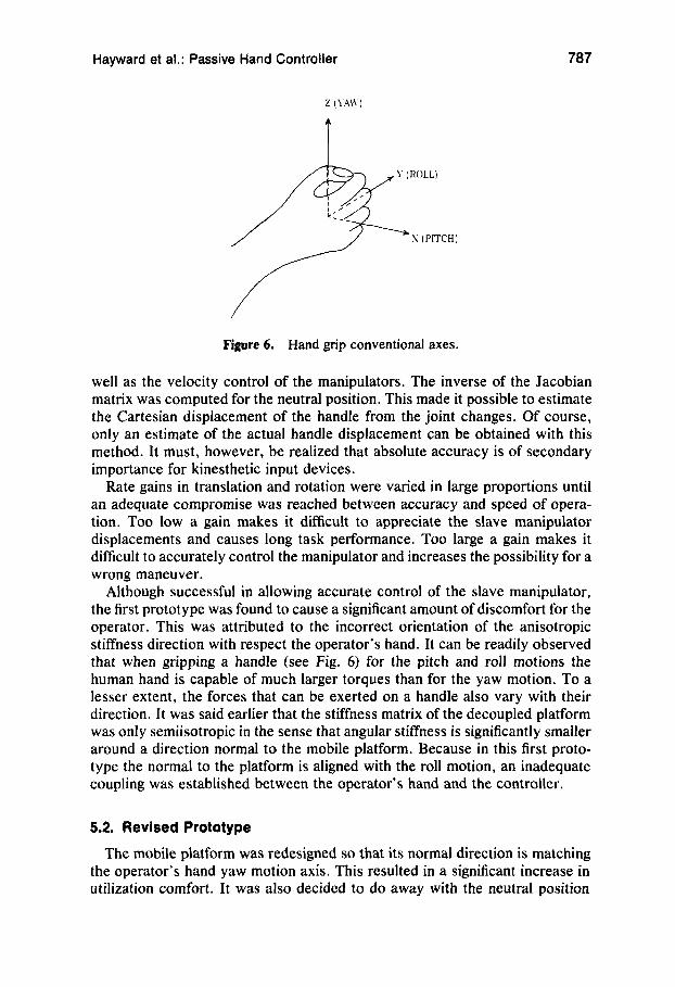
Figure 6. Hand grip conventional axes.
well as the velocity control of the manipulators. The inverse of the Jacobian matrix was computed for the neutral position. This made it possible to estimate the Cartesian displacement of the handle from the joint changes. Of course, only an estimate of the actual handle displacement can be obtained with this method. It must, however, be realized that absolute accuracy is of secondary importance for kinesthetic input devices.
Rate gains in translation and rotation were varied in large proportions until an adequate compromise was reached between accuracy and speed of opera- tion. Too low a gain makes it difficult to appreciate the slave manipulator displacements and causes long task performance. Too large a gain makes it difficult to accurately control the manipulator and increases the possibility for a wrong maneuver.
Although successful in allowing accurate control of the slave manipulator, the first prototype was found to cause a significant amount of discomfort for the operator. This was attributed to the incorrect orientation of the anisotropic stiffness direction with respect the operator’s hand. It can be readily observed that when gripping a handle (see Fig. 6) for the pitch and roll motions the human hand is capable of much larger torques than for the yaw motion. To a lesser extent, the forces that can be exerted on a handle also vary with their direction. It was said earlier that the stiffness matrix of the decoupled platform was only semiisotropic in the sense that angular stiffness is significantly smaller around a direction normal to the mobile platform. Because in this first proto- type the normal to the platform is aligned with the roll motion, an inadequate coupling was established between the operator’s hand and the controller.
5.2. Revised Prototype
The mobile platform was redesigned so that its normal direction is matching the operator’s hand yaw motion axis. This resulted in a significant increase in utilization comfort. It was also decided to do away with the neutral position

788 Journal of Robotic Systems-1993
Figure 7. Second prototype. The mechanism has been rotated by 90°, resulting in a horizontal mobile platform (see text). The problem of connecting the handle to the six legs has been solved by a molded piece that is made light and rigid. At the same time, a clean line provide an unambiguous sense of orientation at a glance, increasing the comfort of utilization.
indicator. Justification will be found in the next section. See Figure 7 for a view of the resulting system.
The design of the legs was significantly updated as well. Eliminating the neutral point nonlinearity made the construction much simpler. Note that the return spring's effect is still obtained using two springs per leg, simplifying construction because each spring is used only in compression and thus is not required to be attached. Moreover, adjustment of the distance between the two struts still can be used to create antagonist loading for a short distance around the neutral point, resulting in a nonlinearity, a change of the spring constant, but not a dead-band. This can be eliminated if desired (see Fig. 8).
Finally, because all the legs undergo the same gravity loading it is easy to compensate for gravity forces. This was done by adding long calibrated exten- sion springs. Because their length variation is small with respect to their aver- age operating length, the force they generate is quasiconstant and almost inde- pendent from the motions of the platform, thus creating minimum disturbance.
5.3. Observations Regarding the Utilization of the Device
Because the workspace is relatively large, spatial displacements are well perceived by the operator. Because of the elimination of couplings, pure straight-line motions or pure angular motions are easily achieved, thus confinn- ing the hypothesis discussed in the second section.

Hayward et al.: Passive Hand Controller 789
Potentiometer ---c
Predsion Steel Shaft
Figure 8. Second leg design. The weight of the moving parts is minimized and an extension spring is added for gravity compensation. The distance between struts can be adjusted for exact linearity or slight antagonism between the two compression springs.
The activation of the device is bound to a trigger button situated under the operator’s finger. This feature allows the relocation of the “zero position” of the hand controller at any location in the workspace, independently of the mechanical neutral position. This simple indexing scheme not only implements a safety “dead-man” feature but also virtually increases the workspace of the device.
In addition, rather unexpected strategies employed by the operators were observed. In particular, when a large-amplitude motion of the slaved manipula- tor was desired the operator would first move the controller in the direction opposite to the desired one, depress the activation trigger, and then move the handle in the desired direction to the neutral position (this also holds for rota- tions). This strategy has the effect of bringing the device back to the neutral position, where forces are small and accurate corrective motions are more easily achieved. Then, of course, releasing the trigger would immediately bring the robot to a stop.

790 Journal of Robotic Systems-1993
The authors acknowledge Prof. Blake Hannaford and the anonymous reviewers for their helpful comments on an earlier draft of this article. The help of John Foldvary has also been instrumental for constructing the prototypes. The contribution of Morton Rosengarten for advice and help on molding techniques is gratefully acknowledged. The financial support from the Natural Sciences and Engineering Research Council of Can- ada, Les Fonds pour la Formation des Chercheurs et I’Aide B la Recherche, QuCbec, and the Institute for Robotics and Intelligent Systems is also gratefully acknowledged.
References
1.
2.
3.
4.
5.
6.
7.
8.
9.
10.
11.
12. 13.
14.
15.
16.
B. Hannaford, “Kinesthetic feedback techniques in teleoperated systems,” in Control and Dynamic Systems, Academic Press, New York, 1991, Vol. 40. S. C. Jacobsen, H. KO, E. K. Iversen, and C. C. Davis, “Antagonist control of a tendon driven manipulator,” Proc. of the International Conf. of Robotics and Automation, 1989, pp. 1334-1339. J. Vertut and P. Coiffet, Robot Technology, in series Teleoperation and Robotics: Evolution and Development, Englewoods Cliffs, NJ, Prentice-Hall, 1986, Vol. 3A. J. K. Salisbury, “Teleoperator hand design issues,” Proc. of the International Conf. of Robotics and Automation, 1986, pp. 1355-1361. D. A. McAffee and P. Fiorini, “Hand controller design requirements and perfor- mance issues in telerobotics,” Proc. of the Fifth International Conf. on Advanced Robotics, 1991, pp. 187-191. K. R. Boff, L. Kaufman, and J. P. Thomas, Handbook of Perception and Human Performance, John Wiley & Sons, New York, 1986. G. Hirzinger and J. Dietrich, “Multisensory robots and sensor based path genera- tion,” Proc. of the International Conf. of Robotics and Automation, 1986, pp.
D. E. Whitney and J. M. Rourke, “Mechanical behavior and design equations for elastomer shear pad remote center of compliance,” ASME J. of Dynamic Sys- tems, Measurement, and Control, 108, 223-232 (1986). J. K. Salisbury, “Active stiffness control of a manipulator in Cartesian coordi- nates,” Proc. of the IEEE Decision and Control Conf., Albuquerque, NM, 1980. Y. Xu and R. P. Paul, “Decoupling compliance mechanisms of robot manipula- tors,” First International Workshop on Advances in Robot Kinematics, Ljubliana, Yugoslavia, 1988. V. Hayward, “Borrowing some design ideas from biological manipulators to de- sign an artificial one,” in Robots and Biological Systems, NATO Series, P. Dario, P. Aebisher, and G. Sandini, Eds., Springer-Verlag, New York, 1992. J. P. Merlet, Les Robots Paralleles, Hermts, Pans, 1990. 0. Ma and J. Angeles, “Optimum architecture design of platform manipulators,” Proc. of the IEEE International Conf. on Robotics and Automation, 1991, pp.
V. Hayward, L. K. Daneshmend, and S. Hayati, “An overview of Kali: A system to program and control cooperative manipulators,” Fourth International Con$ on Advanced Robotics, Columbus, OH, 1989, pp. 547-558. E. F. Fichter, “A Stewart platform based manipulator: general theory and practi- cal construction,” Int. J . of Robotics Research, 5 , (1986). P. Fisher, R. Daniel, and K. V. Siva, “Specification and design of input devices for teleoperation,” Proc. of IEEE International Conf. on Robotics and Automa- tion, Cincinnati, OH, 1990, pp. 540-546.
1992-2001.
1 130- 1 135.


![Kinematic Synthesis with Configuration Spaces ... · Compendiasuch as Artobolevsky's catalog [1] provide a library of known mechanisms indexed bytype (lever mechanisms, e.g.) and](https://img.pdfslide.us/doc/110x75/5b77dbae7f8b9a47518dfb0c/kinematic-synthesis-with-configuration-spaces-compendiasuch-as-artobolevskys.jpg)