Embed Size (px)
Citation preview
GEOMETRIC ANALYSIS OF THE KINEMATIC SENSITIVITY OF PLANARPARALLEL MECHANISMS
Mohammad Hossein Saadatzi1, Mehdi Tale Masouleh2, Hamid D. Taghirad1,Clement Gosselin2, Philippe Cardou2
1K.N. Toosi University of Technology, Tehran, Iran
E-mail: [email protected]; [email protected]
Universite Laval, Quebec, QC, Canada
E-mail: [email protected]; [email protected]; [email protected]
Received July 2011, Accepted October 2011
No. 11-CSME-67, E.I.C. Accession 3307
ABSTRACT
The kinematic sensitivity is a unit-consistent measure that has been recently proposed as amechanism performance index to compare robot architectures. This paper presents a robustgeometric approach for computing this index for the case of planar parallel mechanisms. Thephysical meaning of the kinematic sensitivity is investigated through different combinations ofthe Euclidean and infinity norms and by means of several illustrative examples. Finally, thispaper opens some avenues to the dimensional synthesis of parallel mechanisms by exploring themeaning of the global kinematic sensitivity index.
Keywords: performance index; kinematic sensitivity; planar parallel mechanisms; redundantmechanisms; mechanisms with dependent degrees of freedom.
ANALYSE GEOMETRIQUE DE LA SENSIBILITE CINEMATIQUE DESMECANISMES PARALLELES PLANS
RESUME
La sensibilite cinematique a ete proposee recemment comme un indice de performance pourcomparer les architectures des robots en fonction de leurs proprietes cinematiques. Cet articlepresente une approche geometrique robuste pour calculer la sensibilite cinematique desmecanismes paralleles incluant des exemples illustratifs. Dans cet article, la sensibilitecinematique est etudiee par une combinaison des normes euclidienne et infinie afin d’obtenirla combinaison la plus sensee, d’un point de vue physique. En outre, le present document ouvredes pistes pour la synthese dimensionnelle des mecanismes paralleles en explorant lasignification de l’indice global de sensibilite cinematique.
Mots-cles : indice de performance; sensibilite cinematique; mecanismes paralleles plans;mecanismes paralleles redondants; mecanismes paralleles avec des degres de liberte dependants.
Transactions of the Canadian Society for Mechanical Engineering, Vol. 35, No. 4, 2011 477
1. INTRODUCTION
The definition of sound general performance indices for mechanisms, including ParallelManipulators (PMs), has received much attention from the robotics research community [1].This is due to the need to provide comparisons between different robot architectures [2–4]. Asreviewed in [1], the most notorious indices, namely, the manipulability and the dexterity, stillentail some drawbacks which are well discussed in [1,5–7]. In [1], two distinct metrics areproposed: one for rotations and one for point displacements. They are referred to as thekinematic sensitivity indices. These indices provide tight upper bounds to the magnitudes of theend-effector rotations and point-displacements, respectively, under a unit-magnitude array ofactuated-joint displacements [1].
Hence, the maximum kinematic sensitivity is defined as the maximum error that occurs in theCartesian workspace as a result of bounded displacements in the joint space. In order to obtainconsistent unit, two indices have been defined [1]:
src,f: max
ErEc~1EwEf ,and spc,f
: maxErEc~1
EpEf , ð1Þ
where, w is the array of small rotations of the end-effector about the Cartesian axes, prepresents a small displacement of the operation point, and r is the array of small actuatordisplacements which can be considered as the errors of the actuators. These two indices arereferred to as the maximum rotation and point-displacement sensitivities, respectively. In[1], the definitions of the kinematic sensitivity for serial and parallel mechanisms are basedon the same norm in the constraint and the objective functions, i.e., c~f . Obviously,different norms for the constraint and objective functions of the kinematic sensitivity leadto different indices with different interpretations. This paper aims at investigating andcomparing these different indices, in order to end up with the most meaningful index forplanar parallel mechanisms. As a case study, emphasis will be placed on the 3-RPR parallelmechanism, which is considered a good representative of planar parallel mechanism ingeneral.
Merlet in [8], concluded that the calculation of the mechanism performance indices must bedone while considering independent joint displacements, which immediately leads to c~?. Theresults of this paper confirm this conclusion, and, moreover, provide some new observationsand interpretations on the use of different norms in the kinematic sensitivity indices. This paperalso extends and reviews the approach and routines used in [1] for indices having c~f ~2,which leads to some interesting closed-form solutions, and for indices having c~f ~?, usinglinear programming.
The remainder of this paper is organized as follows. First, the formulation used in [1] forthe Jacobian matrix of parallel mechanisms is reviewed. Then, the methods of computationof the kinematic sensitivity for different combinations of Euclidean and ? norms aredetailed, and illustrated through typical examples for parallel mechanisms. The paperextends the study by presenting the kinematic sensitivity as a global performance index ofthe mechanism, and, finally, the concluding remarks are given to provide more insight intoongoing research.
Transactions of the Canadian Society for Mechanical Engineering, Vol. 35, No. 4, 2011 478
2. KINEMATIC SENSITIVITY OF FULLY-PARALLEL MECHANISMS
Differentiating the loop-closure equations of a planar parallel mechanism results in its first-order kinematics relationship, which can be formulated as follows [1,10]:
r~Kppzkrw, ð2Þ
in which, r [ Rn represents small actuator displacements, with n as the number of actuators, and
x~½pT ,w�T stands for the operation-point position and the orientation, i.e., the pose of the end–effector. Moreover, consider Kp:½k1,k2�, kr:k3 and K:½Kp,kr�. In parallel manipulators,according to Eq. (2), constraint ErEcƒ1 may be rewritten as EKxEcƒ1, which represents the setof possible pose errors for unit bounds of the (small) actuator displacement errors. EKxE?ƒ1and EKxE2ƒ1 can be geometrically represented by a polyhedron and ellipsoid in R3,respectively. These geometric interpretations are used in this paper to compute the kinematicsensitivity of the mechanisms under study.
2.1. Kinematic Sensitivity in the Case c~? and f ~f2,?gThe constraint EKxE?ƒ1 represents a zonotope in R3. Since the objectives of Eq. (1) are both
convex functions to be maximized, the optimum is bound to occur at a vertex of the zonotope.The maximum objective value among all vertices are labelled sr?,? for the rotational part andsp?,? for the point-displacement part. The maximum 2–norms of the rotational and point-displacement parts are denoted by sr?,2
and sp?,2, respectively. In order to compute sr?,2
andsp?,2
, one may proceed by vertex enumeration, i.e., compute the 2–norms associated with eachvertex and retain the largest. Thus, as the first step, the coordinates of these vertices should beobtained, and to do so, the above constraint is formulated as follows:
LDx,16, ð3Þ
in which, L:½KT{KT �T , A denotes the componentwise inequality, where 16:½11 � � � 1�T[R6.Each row of Eq. (3) can be regarded as a plane containing a facet of the constraint polyhedron.The vertices of this zonotope are determined by the intersection points of differentcombinations of three independent rows of Eq. (3). Each vertex can be obtained by multiplyingthe vector 13 with the inverse of the matrix formed by the corresponding independent rows. Thiszonotope has 2n vertices and is symmetrical about the origin. Thus the computation of thekinematic sensitivity requires only the examination of half of the vertices.
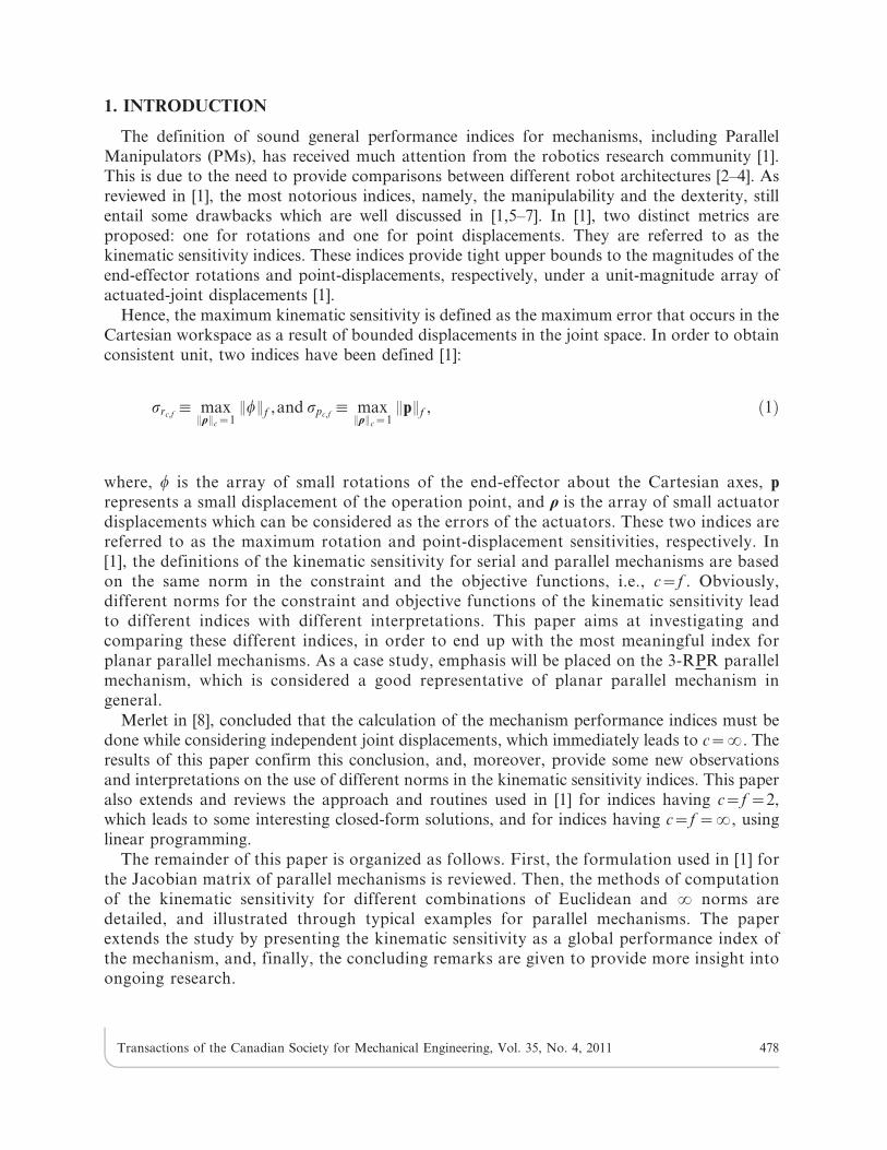
As a case study, let us consider the 3-RPR parallel mechanism shown in Fig. 1, which in agiven posture has the Jacobian matrix [11–13]
K~
0:5456 0:8380 0:0535
{0:8080 0:5892 0:5892
{0:8588 {0:5123 0:9999
264
375: ð4Þ
To obtain sp,?,? and sp,?,2, the constraint equation is EKxE?ƒ1. This constraint is equivalentto
Transactions of the Canadian Society for Mechanical Engineering, Vol. 35, No. 4, 2011 479
0:5456 0:8380 0:0535
{0:8080 0:5892 0:5892
{0:8588 {0:5123 0:9999
{0:5456 {0:8380 {0:0535
0:8080 {0:5892 {0:5892
0:8588 0:5123 {0:9999
2666666664
3777777775
x
y
w
264375,
1
1
1
1
1
1
2666666664
3777777775: ð5Þ
The above can be made equivalent to a polyhedron that has eight vertices. Note that thispolyhedron is symmetric about the origin, and therefore, it is sufficient to compute a half of thevertices vi~(xi,yi,wi), i~1, . . . ,4. This can be done by considering four subsystems of threeequations. For instance, upon considering the first two equations combined in turns with thethe third, the fourth, the fifth and the sixth equation, we obtain the vertices
v1~
0:6189
0:6706
1:8752
264
375, v2~
2:8143
{0:8301
2:9921
264
375, v3~
1:6415
0:0952
0:4586
264
375, v4~
{0:5539
1:5959
{0:6582
264
375: ð6Þ
The remaining vertices, are merely the opposites of the latter, but they are not required forcomputing the kinematic sensitivity. According to the definition of the kinematic sensitivity,when c~?, we have
sp?,?~ max ( maxi~1,...,8
xi, maxi~1,...,8
yi)~ max ( maxi~1,...,4
jxij, maxi~1,...,4
jyij)~2:8143, ð7Þ
sp?,2~
ffiffiffiffiffiffiffiffiffiffiffiffiffiffiffiffiffiffiffiffiffiffiffiffiffiffiffimax
i~1,...,8x2
i zy2i
r~
ffiffiffiffiffiffiffiffiffiffiffiffiffiffiffiffiffiffiffiffiffiffiffiffiffiffiffimax
i~1,...,4x2
i zy2i
r~2:9342, ð8Þ
Fig. 1. Schematic representation of a planar 3-RPR parallel mechanism [9].
Transactions of the Canadian Society for Mechanical Engineering, Vol. 35, No. 4, 2011 480
sr?,?~sr?,2~ max
i~1,...,8wi~ max
i~1,...,4jwij~2:9921
rad
m: ð9Þ
Note that the mechanism actuators are linear, so the unit of error in the joint space is meter (m),and the unit of moving platform translational and rotational errors in the workspace are meter(m) and radian (rad/s), respectively; hence spc,f
in Eqs. (7) and (8) has no unit, and the unit of src,f
in Eq. (9) israd
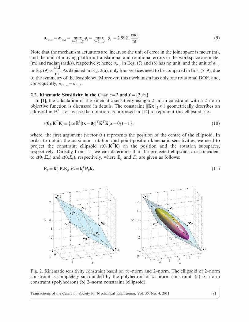
m. As depicted in Fig. 2(a), only four vertices need to be compared in Eqs. (7–9), due
to the symmetry of the feasible set. Moreover, this mechanism has only one rotational DOF, and,consequently, sr?,?~sr?,2
.
2.2. Kinematic Sensitivity in the Case c~2 and f ~f2,?gIn [1], the calculation of the kinematic sensitivity using a 2–norm constraint with a 2–norm
objective function is discussed in details. The constraint EKxE2ƒ1 geometrically describes anellipsoid in R3. Let us use the notation as proposed in [14] to represent this ellipsoid, i.e.,
e(03,KT K):fx[R3j(x{03)T KT K(x{03)~1g, ð10Þ
where, the first argument (vector 03) represents the position of the centre of the ellipsoid. Inorder to obtain the maximum rotation and point-position kinematic sensitivities, we need toproject the constraint ellipsoid e(03,KT K) on the position and the rotation subspaces,respectively. Directly from [1], we can determine that the projected ellipsoids are coincidentto e(02,Ep) and e(0,Er), respectively, where Ep and Er are given as follows:
Ep~KTp PrKp,Er~kT
r Ppkr, ð11Þ
Fig. 2. Kinematic sensitivity constraint based on ?–norm and 2–norm. The ellipsoid of 2–normconstraint is completely surrounded by the polyhedron of ?–norm constraint. (a) ?–normconstraint (polyhedron) (b) 2–norm constraint (ellipsoid).
Transactions of the Canadian Society for Mechanical Engineering, Vol. 35, No. 4, 2011 481
Pr:13|3{Kr(KTr Kr)
{1KTr ,Pp:13|3{Kp(KT
p Kp){1KTp : ð12Þ
Having computed the projections of ellipsoid e(03,KT K) on rotation and point-positionsubspaces, we may compute the lengths of their semimajor axes, which yield the correspondingkinematic sensitivities:
sp2,2~
ffiffiffiffiffiffiffiffiffiffiffiffiffiffiffiffiEE{1
p E2
q~
1ffiffiffiffiffiffiffiffiffimini~1,2
qlp,i
, sr2,2~
ffiffiffiffiffiffiffiffiffiE{1
r
q, ð13Þ
In these relations, lp,i, i~1,2, represent the eigenvalues of Ep. The same procedure may be usedto compute the maximum error in every direction, xi, i~1,2,3, of the Cartesian workspace,resulting from errors bounded by the 2–norm in the joint space (ErE2ƒ1). Skippingmathematical details, we obtain the projection of constraint ellipsoid e(03,KT K) along the axisxi, which we denote by e(0,Ei)
Ei~kTi P{iki, P{i:13|3{K{i(K
T{iK{i)
{1KT{i, ð14Þ
in which, K{i is the Jacobian matrix K without its ith column ki. As e(0,Ei) is the projection onthe axis, it is not an ellipsoid any more, but rather an interval centred at the origin, with Ei as itsinverse squared half-length. According to the definition of the kinematic sensitivities using the2–norm constraint and the ?–norm objective function, these indices may be computed as
sp2,?~ maxi~1,2
di, sr2,?~d3, ð15Þ
where di~1ffiffiffiffiffiEi
p is the farthest distance along the xi axis.
In order to illustrate the derivation of these values, consider the case study of the 3-RPRwhose Jacobian matrix is momentarily given by matrix K of Eq. (4). We wish to compute thekinematic sensitivity based on the 2–norm constraint for this example. From Eq. (12), we have
Pr~
0:9979 {0:0234 {0:0396
{0:0234 0:7428 {0:4365
{0:0396 {0:4365 0:2593
264
375, Ep~
0:4253 0:3049
0:3049 1:3012
� �, ð16Þ
Pp~P{3~
0:4154 {0:1988 0:4509
{0:1988 0:0951 {0:2158
0:4509 {0:2158 0:4895
264
375, Er~E3~0:3051
m2
rad2: ð17Þ
Using Eq. (13), one may derive
sp2,2~
ffiffiffiffiffiffiffiffiffiffiffiffiffiffiffiffiEE{1
p E2
q~1:7418, sr2,2
~
ffiffiffiffiffiffiffiffiffiffiffiffiffiffiffiffiEE{1
r E2
q~
1ffiffiffiffiffiffiE3
p ~1:8106rad
m: ð18Þ
Transactions of the Canadian Society for Mechanical Engineering, Vol. 35, No. 4, 2011 482
As the mechanism has only one rotational DOF, it follows that sr2,?~sr2,2. In turn, from
Eq. (14), the maximum distance along the x and y axes is obtained as
K{x~
0:8380 0:0535
0:5892 0:5892
{0:5123 0:9999
264
375, P{x~
0:4520 {0:4390 0:2345
{0:4390 0:4264 {0:2277
0:2345 {0:2277 0:1217
264
375, Ex~0:3538, ð19Þ
K{y~
0:5456 0:0535
{0:8080 0:5892
{0:8588 0:9999
264
375, P{y~
0:1587 0:3110 {0:1918
0:3110 0:6095 {0:3758
{0:1918 {0:3758 0:2317
264
375, Ey~1:0826: ð20Þ
where, dx~1:6811 and dy~0:9611. From Eq. (15), we reach sp2,?~ max (dx,dy)~1:6811.
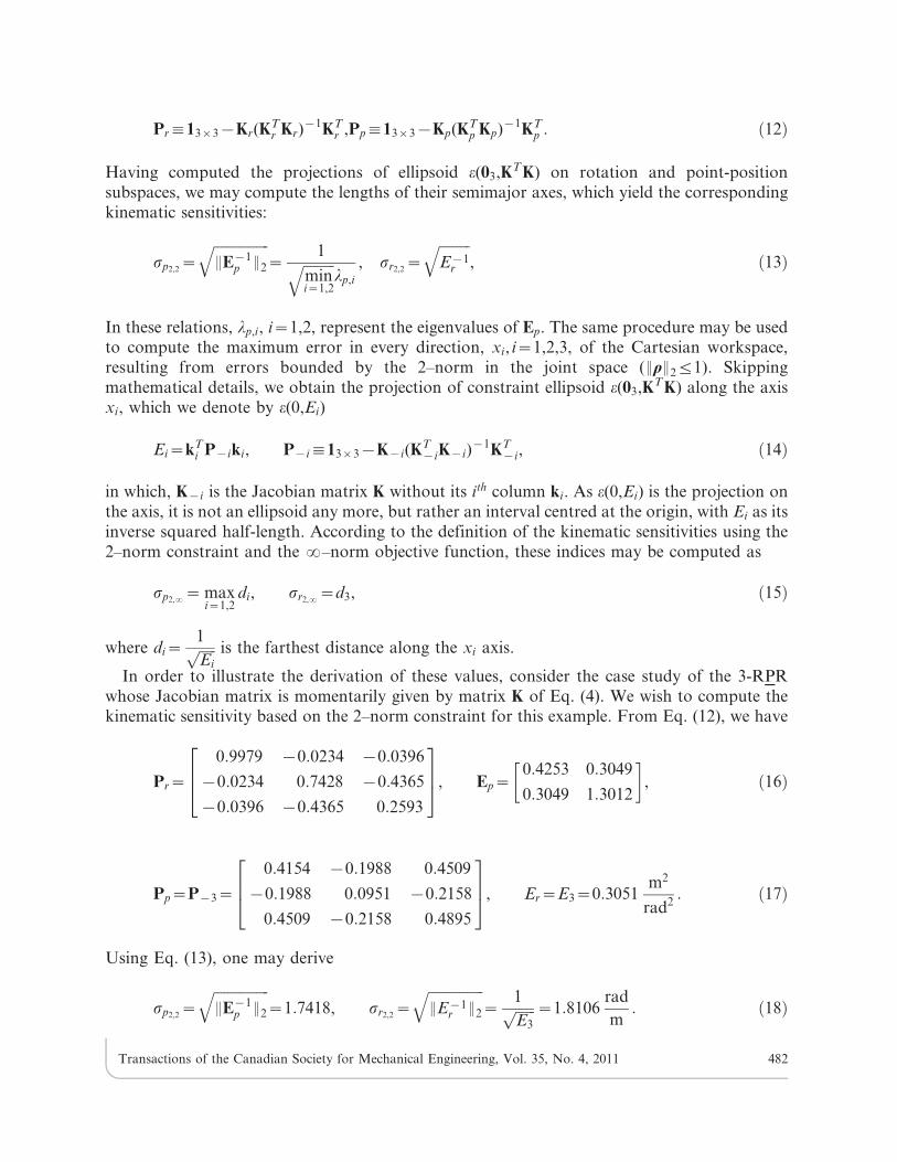
2.3. Comparison Between Different Variations of the Kinematic SensitivityFigure 3 shows a geometric representation of different versions of the kinematic sensitivity.
According to this figure, different kinematic sensitivity measures are related through thefollowing inequalities:
s?,2§s?,?§s2,?, s?,2§s2,2§s2,?: ð21Þ
There is no such relationship between s?,? and s2,2. According to Fig. 3, if the constraintellipsoid or polyhedron rotates, the value of s?,? and s2,? would change in consequence whilethe value of s?,2 and s2,2 remain the same. Also, it should be noted that a change incoordinates, although affecting the Jacobian of the mechanism for a given pose, should notaffect its kinematic sensitivity index. Because of this frame–invariant requirement, it may beconcluded that it is preferable to compute the norm of x using the 2–norm. Coupling this with
Fig. 3. Geometrical representation of different variations of kinematic sensitivity in the case of aconstrained manipulator.
Transactions of the Canadian Society for Mechanical Engineering, Vol. 35, No. 4, 2011 483
the idea proposed by Merlet in [8,13], according to which the constraint should be defined withthe ?–norm, s?,2 stands out as the most meaningful index for the calculation of the point-displacement and rotation kinematic sensitivities.
3. KINEMATIC SENSITIVITY IN THE CASE OF REDUNDANT PARALLELMECHANISMS
Redundant parallel manipulators have been introduced to alleviate some of the shortcomingsof fully parallel mechanisms in terms of kinematic properties, such as their large singularity loci[15–16]. In this section, the kinematic sensitivity of redundant planar parallel mechanisms isinvestigated in order to gain a better understanding of their kinematic properties compared tothose of fully parallel mechanisms.
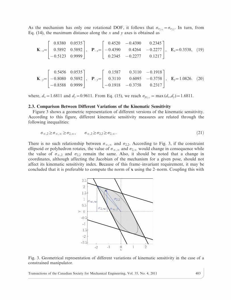
In redundant mechanisms, the number of planes generated by the ?–norm constraintincreases and further confines the feasible set. Figure 4(a) and Fig. 4(b) represent respectivelythe kinematic sensitivity constraints, EKxEcƒ1, for a non-redundant and redundant mechanism(a 2-RPR and a 3-RPR mechanism with zero length of moving platform). As shown in Fig. 4(b),if the redundant rows–corresponding to the redundant limbs–constrain the feasible polyhedronmore tightly, they will reduce the mechanism kinematic sensitivities. In redundant mechanisms,the number of vertices of the zonotope generated by the ?–norm constraint increases.Nevertheless, these vertices can be yet determined by considering all possible subsets of threeindependent rows in Eq. (3). It should be noted that some of the intersection points of thesetriplets of plane constraints lie outside the feasible polyhedron, as depicted in Fig. 4(b).Reaching this step, one should verify whether the obtained point satisfies the remaininginequalities of Eq. (3). If not, then it is not a true vertex.
In order to illustrate the effects of redundancy, consider the previous 3-RPR parallelmechanism, whose Jacobian matrix K is given in Eq. (4). Assume that the legs of themanipulator are all connected at the origin O0 of the moving frame, which results in a redundantmechanism that has only two DOFs (planar point-displacements x~½x,y�T ), and, therefore, theassociated Jacobian matrix has three rows and two columns. Considering only the first twoactuators, r1 and r2, the first-order kinematics relationship of this mechanism results in
Fig. 4. ?–norm and 2–norm constraints, (a) a non-redundant and (b) a redundant mechanismin a given pose. The representations of other indices are omitted to avoid overloading the figure,see Fig. 3 for more information. (a) non-redundant mechanism constraint, s2,2~1:056 ands?,2~1:453 (b) redundant mechanism constraint, s2,2~0:963 and s?,2~1:3782.
Transactions of the Canadian Society for Mechanical Engineering, Vol. 35, No. 4, 2011 484
r1,r2½ �T~K2|2x, where, K2|2~0:5456 0:8380
{0:8080 0:5892
� �ð22Þ
In this case, the constraint ellipse is represented by the equation
(0:5456xz0:8380y)2z({0:8080xz0:5892y)2~1: ð23Þ
Figure 4(a) depicts the constraint ellipse and polygon corresponding to the given Jacobian.Now, assume that the third limb of the redundant 2-DOF mechanism becomes active, while thepose of the end effector remains unchanged. Then Jacobian matrix takes the following form:
r1,r2,r3½ �~K3|2
x
y
� �, where K3|2~
0:5456 0:8380
{0:8080 0:5892
{0:8588 {0:5123
264
375: ð24Þ
In this case, the constraint ellipsoid is
(0:5456xz0:8380y)2z({0:8080xz0:5892y)2z({0:8588x{0:5123y)2~1: ð25Þ
It should be noted that the constraint ellipsoid of a redundant mechanism, lie inside theconstraint ellipsoid of the non-redundant mechanism obtained by removing some of its legs,and taken in the same posture. Therefore, the kinematic sensitivity is larger or equal to that ofthe latter. Using the ?-norm in the constraint leads to a similar conclusion. The number ofplanes that bound the constraint polyhedron is increased in the case of redundant mechanisms,and the constraint polyhedron becomes smaller or remains the same. Thus, the kinematicsensitivity may either decrease or remain the same in the corresponding redundant manipulator.
From the above (Eqs. (23) and (25)) it follows that upon transforming a fully actuatedmechanism into a redundant one, by adding one limb, one term would be added to theexpression defining the constraint ellipsoid which makes the constraint shape smaller. Based onthe latter mathematical reasoning, which is based on the 2-norm constraint, one would draw anerroneous conclusion that making a mechanism redundant, would definitely decrease thekinematic sensitivity compared with the one of its former fully actuated mechanism. In fact, thekinematic sensitivity would decrease or not, based on the pose and the design parameters ofthe mechanism. This is coherent with the ?-norm and makes it more credible than the 2–normconstraint. This reconfirms that the constraint of kinematic sensitivity must be computed using?–norm and this is consistent with the conclusion reached in [8,13].
In order to clarify this issue, assume an exaggerated example, where two of the legs of aredundant 4-RPR planar parallel mechanism coincide exactly. From intuition, the dexterity ofsuch a manipulator should be the same as that of the 3-RPR one obtained by removing one ofthe redundant legs. In this case, exploring the kinematic sensitivity using a 2–norm constraint inthe definition of the kinematic sensitivity, will result in a smaller constraint ellipsoid in the caseof the redundant manipulator, and the kinematic sensitivity associated with the latter will besmaller. If the problem is explored using an ?–norm constraint, however, the redundant planesin the Cartesian workspace are coincident, just as their corresponding legs. Therefore, the shape
Transactions of the Canadian Society for Mechanical Engineering, Vol. 35, No. 4, 2011 485
and size of the polyhedron constraint remains unchanged, and the kinematic sensitivity isinvariant as it should be.
4. KINEMATIC SENSITIVITY OF PARALLEL MECHANISMS WITH DEPENDENTDOF
This section is devoted to the computation of the kinematic sensitivity for planar parallelmechanisms with dependent DOF. In this kind of mechanisms, the Jacobian matrix takes theform
r
0
� �~
Kactuation
Kconstraint
� �x: ð26Þ
Failing to consider the equations 0~Kconstraintx in the kinematic sensitivity analysis leads to anunbounded constraint set EKactuationxEƒ1. This is due to the fact that Kactuation does not havefull-column rank. Hence, the appropriate method for computing the kinematic sensitivity musttake into account both the equality constraint Kconstraintx~0 and the inequality constraintEKactuationxEƒ1.
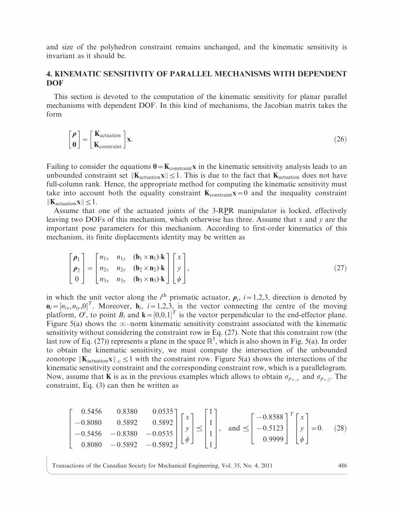
Assume that one of the actuated joints of the 3-RPR manipulator is locked, effectivelyleaving two DOFs of this mechanism, which otherwise has three. Assume that x and y are theimportant pose parameters for this mechanism. According to first-order kinematics of thismechanism, its finite displacements identity may be written as
r1
r2
0
264
375~
n1x n1y (b1|n1):k
n2x n2y (b2|n2):k
n3x n3y (b3|n3):k
264
375
x
y
w
264375, ð27Þ
in which the unit vector along the ith prismatic actuator, ri, i~1,2,3, direction is denoted byni~½nix,niy,0�T . Moreover, bi, i~1,2,3, is the vector connecting the centre of the movingplatform, O0, to point Bi and k~½0,0,1�T is the vector perpendicular to the end-effector plane.Figure 5(a) shows the ?–norm kinematic sensitivity constraint associated with the kinematicsensitivity without considering the constraint row in Eq. (27). Note that this constraint row (thelast row of Eq. (27)) represents a plane in the space R3, which is also shown in Fig. 5(a). In orderto obtain the kinematic sensitivity, we must compute the intersection of the unboundedzonotope EKactuationxE?ƒ1 with the constraint row. Figure 5(a) shows the intersections of thekinematic sensitivity constraint and the corresponding constraint row, which is a parallelogram.Now, assume that K is as in the previous examples which allows to obtain sp?,? and sp?,2
. Theconstraint, Eq. (3) can then be written as
0:5456 0:8380 0:0535
{0:8080 0:5892 0:5892
{0:5456 {0:8380 {0:0535
0:8080 {0:5892 {0:5892
26664
37775
x
y
w
264375,
1
1
1
1
26664
37775, and ,
{0:8588
{0:5123
0:9999
264
375
Tx
y
w
264375~0: ð28Þ
Transactions of the Canadian Society for Mechanical Engineering, Vol. 35, No. 4, 2011 486
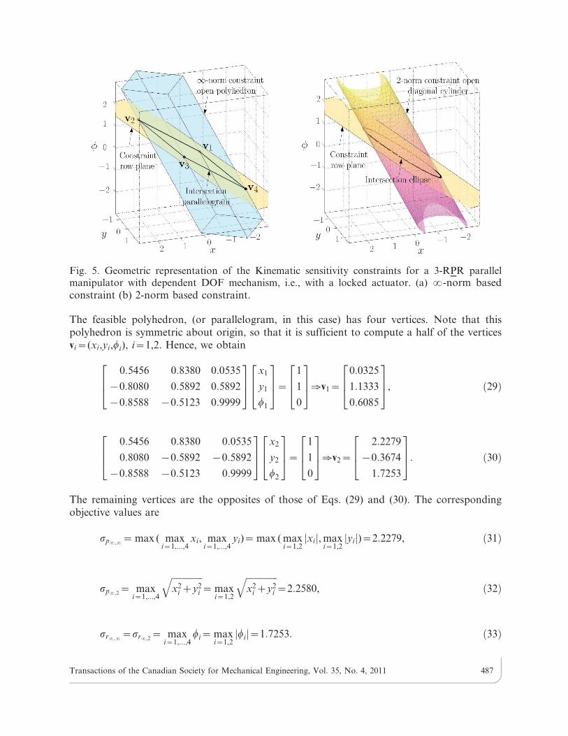
The feasible polyhedron, (or parallelogram, in this case) has four vertices. Note that thispolyhedron is symmetric about origin, so that it is sufficient to compute a half of the verticesvi~(xi,yi,wi), i~1,2. Hence, we obtain
0:5456 0:8380 0:0535
{0:8080 0:5892 0:5892
{0:8588 {0:5123 0:9999
264
375
x1
y1
w1
264
375~
1
1
0
264375[v1~
0:0325
1:1333
0:6085
264
375, ð29Þ
0:5456 0:8380 0:0535
0:8080 {0:5892 {0:5892
{0:8588 {0:5123 0:9999
264
375
x2
y2
w2
264
375~
1
1
0
264375[v2~
2:2279
{0:3674
1:7253
264
375: ð30Þ
The remaining vertices are the opposites of those of Eqs. (29) and (30). The correspondingobjective values are
sp?,?~ max ( maxi~1,...,4
xi, maxi~1,...,4
yi)~ max ( maxi~1,2jxij, max
i~1,2jyij)~2:2279, ð31Þ
sp?,2~ max
i~1,...,4
ffiffiffiffiffiffiffiffiffiffiffiffiffiffix2
i zy2i
q~ max
i~1,2
ffiffiffiffiffiffiffiffiffiffiffiffiffiffix2
i zy2i
q~2:2580, ð32Þ
sr?,?~sr?,2~ max
i~1,...,4wi~ max
i~1,2jwij~1:7253: ð33Þ
Fig. 5. Geometric representation of the Kinematic sensitivity constraints for a 3-RPR parallelmanipulator with dependent DOF mechanism, i.e., with a locked actuator. (a) ?-norm basedconstraint (b) 2-norm based constraint.
Transactions of the Canadian Society for Mechanical Engineering, Vol. 35, No. 4, 2011 487
The kinematic sensitivity based on 2–norm constraints may be computed in a similar way whenone of the mechanism actuated joints is locked. Figure 5(b) shows the ellipse of the 2-normconstraint obtained from the intersection of the ellipsoidal cylinder EKxE2ƒ1 and the plane ofthe constraint corresponding to the locked joint.
5. KINEMATIC SENSITIVITY AS A GLOBAL PERFORMANCE INDEX
Since the kinetostatic indices generally depend on the pose of the mobile platform, the nextstep consists of extending them to all the reachable poses of the mechanism. Following thereasoning presented in [17], instead of considering the index I for a specific pose, a global indexfI covering the manipulator workspace W is introduced as:
fI~
ÐW
IdWÐW
dW: ð34Þ
Notice that when there are singular poses within the mechanim workspace W , and it is appliedfor sp?,2 and sr?,2, fI tends towards infinity. Therefore, it is difficult to compare twomechanisms that have at least one singular point in their workspace, as it is not clear whetherthe integral
ÐW
IdW converges or not. In the case where a dimensional-synthesis method wouldguarantee the absence of singular poses, then Eq. (34) would hold over the entire workspace,otherwise, however, in general, freeing the whole workspace from all singular poses isimpossible, and, consequently, there is a need for a more robust global index. To circumventthis problem, consider the reasoning applied to the condition number in [17]. Point-displacement and rotation sensitivities are bounded between zero and infinity, and hence, theirinverse are not helpful over the same interval. As the minimization of the variation of theseindices is of interest, the maximization of the inverse of their offshoot is suggested in this paper,i.e., we define
s0r,2~1
1zsr,2, s0p,2~
1
1zsp,2, [ 0ƒs0r,2ƒ1, 0ƒs0p,2ƒ1: ð35Þ
The above indices are well defined, and may be used for optimization purposes [10,18].
6. CONCLUSIONS
This paper investigated the interpretation and calculation of different variations of thekinematic sensitivity of planar parallel mechanisms. As a case study, the 3-RPR planarmechanism was analysed and the corresponding kinematic sensitivities were given geometricinterpretations. Analytical relationships to compute each of the variations were obtained anddiscussed. Moreover, the calculation of the kinematic sensitivity in the case of redundant anddependent-DOF planar parallel mechanisms are investigated, and some new observations arereported. Finally, the kinematic sensitivity is extended to be considered as a global performanceindex for optimization purposes. The principles of this paper can be applied equally well to theother types of parallel mechanisms, such as the Stewart–Gough platform. Ongoing workincludes, the development of a robust approach to obtain representative global kinematicsensitivity for optimization purposes.
Transactions of the Canadian Society for Mechanical Engineering, Vol. 35, No. 4, 2011 488
ACKNOWLEDGEMENTS
The authors would like to acknowledge the financial support of the Natural Sciences andEngineering Research Council of Canada (NSERC), the Canada Research Chair program andthe Iran National Science Foundation (INSF) research grant.
REFERENCES
1. Cardou, P., Bouchard, S. and Gosselin, C., ‘‘Kinematic-sensitivity indices for dimensionallynonhomogeneous jacobian matrices,’’ IEEE Transactions on Robotics and Automation, Vol. 26,No. 1, pp. 166–173, 2010.
2. Briot, S. and Bonev, I. A., ‘‘Are parallel robots more accurate than serial robots?,’’ Transactions
of the Canadian Society for Mechanical Engineering, Vol. 31, No. 4, pp. 445–456, 2007.
3. Binaud, N., Caro, S. and Wenger, P., ‘‘Sensitivity comparison of planar parallel manipulators,’’Mechanism and Machine Theory, Vol. 45, No. 11, pp. 1477–1490, 2010.
4. Binaud, N., Caro, S. and Wenger, P., ‘‘Comparison of 3-RPR planar parallel manipulators withregard to their kinetostatic performance and sensitivity to geometric uncertainties,’’ Meccanica,Vol. 46, pp. 75–88, 2011.
5. Yoshikawa, T., ‘‘Manipulability of robotic mechanisms,’’ The International Journal of Robotics
Research, Vol. 4, No. 2, pp. 3.
6. Khan, W. A. and Angeles, J., ‘‘The kinetostatic optimization of robotic manipulators: theinverse and the direct problems,’’ Journal of Mechanical Design, Vol. 128, No. 1, pp. 168–178,2006.
7. Stocco, L. J., Salcudean, S. E. and Sassani, F., ‘‘On the use of scaling matrices for task-specific robot design,’’ IEEE Transactions on Robotics and Automation, Vol. 15, No. 5,pp. 958–965.
8. Merlet, J. P., ‘‘Jacobian, manipulability, condition number, and accuracy of parallel robots,’’Journal of Mechanical Design, Vol. 128, No. 1, pp. 199–206, 2006.
9. Bonev, I. A., Geometric Analysis of Parallel Mechanisms. Ph.D. thesis, Laval University,Quebec, QC, Canada, October 2002.
10. Saadatzi, M. H., Tale Masouleh, M., Taghirad, H. D., Gosselin, C. and Teshnehlab, M.,‘‘Multi-objective scale independent optimization of 3-RPR parallel mechanisms,’’ InProceedings of the IFToMM 2011.
11. Bonev, I. A., Zlatanov, D. and Gosselin, C., ‘‘Singularity analysis of 3-dof planar parallelmechanisms via screw theory,’’ Journal of Mechanical Design, Vol. 125, No. 3, pp. 573–581,2003.
12. Jiang, Q. and Gosselin, C., ‘‘Geometric synthesis of planar 3-RPR parallel mechanisms forsingularity-free workspace,’’ Transactions of the Canadian Society for Mechanical Engineering,Vol. 33, No. 4, pp. 667–678, 2009.
13. Merlet, J. P., Parallel Robots. Springer-Verlag New York Inc, 2006.
14. Ros, L., Sabater, A. and Thomas, F., ‘‘An ellipsoidal calculus based on propagation andfusion,’’ IEEE Transactions on Systems, Man. and Cybernetics, Part B:Cybernetic, Vol. 32,No. 4, pp. 430–442.
15. Ebrahimi, I., Carretero, J. A. and Boudreau, R., ‘‘A family of kinematically redundant planarparallel manipulators,’’ Journal of Mechanical Design, Vol. 130, pp. 062306, 2008.
16. Rakotomanga, N. and Bonev, I. A., ‘‘Completely eliminating the singularities of a 3-dof planarparallel robot with only one degree of actuator redundancy,’’ Proceedings of the 2010 ASME
Design Engineering Technical Conferences, DETC2010-28829.
Transactions of the Canadian Society for Mechanical Engineering, Vol. 35, No. 4, 2011 489
17. Gosselin, C., Kinematic Analysis, Optimization and Programming of Parallel Robotic
Manipulators. Ph.D. thesis, Department of Mechanical Engineering, McGill University,Montreal, Canada, 1988.
18. Saadatzi, M. H., Tale Masouleh, M., Taghirad, H. D., Gosselin, C. and Cardou, P., ‘‘On theoptimum design of 3-RPR parallel mechanisms,’’ Proceeding of the 19th Iranian Conference onElectrical Engineering (ICEE 2011).
Transactions of the Canadian Society for Mechanical Engineering, Vol. 35, No. 4, 2011 490