Embed Size (px)
Citation preview

Ken Youssefi Mechanical Engineering Dept. 1
Force AnalysisKinetic analysis has to be performed to design the shape and thickness of the links, the joints and to determine the required input torque/force and the resulting output torque/force.
Known:
• The length of all links; r1, r2, r3, and r4
• The results of position, velocity, and acceleration analysis;
θ3, θ4, 3, 4, and α3, α4
• Input information; θ2, 2, α2, and T2 (torque)
• All external loads acting on the links
Unknown:
• Forces acting on all joints; FO2, FA, FB, and FO4
• Inertia forces acting on all links; FI2, FI3, FI4,
• Inertia torques acting on all links; TI2, TI3, TI4,
• The input torque (or force) needed to obtain the
required output torque (or force)
O4
Force analysis of a 4-BarA
B
O2
2
3
4ω2
α2

Force Analysis
Ken Youssefi Mechanical Engineering Dept. 2
Assume the input torque is applied in the opposite direction of the motion to stop the mechanism from moving. This results the mechanism to be in equilibrium
• Graphical method, construct the force polygon
• Analytical method, matrix method (Draw FBD of each link and use static equilibrium condition)

Ken Youssefi Mechanical Engineering Dept. 3
Force Analysis – Static Equilibrium
Static equilibrium – 2D case
∑ Fx = 0, ∑ Fy = 0, ∑ M = 0
Two force members – only two forces acting, one at each joint.
A rigid link acted on by two forces is in static equilibrium only if the two forces are collinear and have the same magnitude in opposite direction
F1 = - F2
X
X

Ken Youssefi+ Mechanical Engineering Dept. 4
Force Analysis – Static Equilibrium
Three force members – only three forces act on a link. Either three joint forces, or two joint forces and an external or inertia or gravitational force.
The link is in static equilibrium only if the force-vectors add up to zero and they pass through the same point (summation of moment about that point is zero).

Ken Youssefi Mechanical Engineering Dept. 5
Force Analysis – Graphical Method
O2 O42
34
P = 120 lb
A
B
C
O2A = 3, AB = O4B = 6, O4C = 4.5,
O2O4 = 2.4
Find the input torque, T2 , to maintain static equilibrium at the position shown or what should be the input torque to exert 120 lb of force for the position shown. Use graphical method, construct force polygon.
AB is a two force member, F34 (force of link3 on link 4) has to be collinear to link 3.
M
Parallel to link3
F34
F14Direction of F14 has to pass through point M
Free-Body Diagram of link 4B
O4
P = 120 lb

Ken Youssefi Mechanical Engineering Dept. 6
Force Analysis – Graphical Method
B
O4
P = 120 lb
F34
F14
M
Force polygon
Parallel to F34 direction
P = 120 lb
Draw and scale force P1 -
Parallel to F14 direction
Draw two lines parallel to F14 and F34 directions from the two ends of vector P
2 -
F34 = 113.52 lb.
Locate the intersection, complete the polygon and scale the force F34
3 -

Ken Youssefi Mechanical Engineering Dept. 7
Force Analysis – Graphical Method
Free-Body Diagram of link 3
3
A
B
F43
F23 = F43 = 113.52
T2 = (F32)(d) = 113.52 x 2.428 = 275.6 in-lb (ccw)
Free-Body Diagram of link 2
Draw and scale link 2, O2A = 3
Scale the perpendicular distance from O2 to the force F32
d = 2.428
AO22
F32 = 113.52
F12 = 113.52 lb

Ken Youssefi Mechanical Engineering Dept. 8
Force Analysis – Graphical Method Principle of Superposition
Principle of superposition can be used to solve problems involving linear systems by considering each of the inputs to the system separately. And then, combine the individual results to obtain the total response of the system.
In linear systems the output (response) is directly proportional to the input, linear relationship between the output and the input exist.
O2 O42
34
A
B
C
D
PQ
O2 O42
34
A
B
C
O2 O42
34
A
B
D
P Q
= +
T2 = (T2) Due to force P + (T2) Due to force Q

Ken Youssefi Mechanical Engineering Dept. 9
Dynamic Force AnalysisInertia forces and D’Alembert’s Principle
An unbalanced set of forces acting on a rigid body
=
The translation and rotation caused by the unbalanced forces
Resultant force R = ∑ F
R = (mass)(linear acceleration of the center of gravity), R = (m)aG
MG = (area moment of inertia)(angular acceleration) = IGα = (R)(h)

Ken Youssefi Mechanical Engineering Dept. 10
Dynamic Force Analysis
D’Alembert’s Principle
R - (m)aG = 0, inertia force = FI = - maG
The inertia force has magnitude of maG and it acts in the opposite
direction of linear acceleration. It stops motion.
The inertia torque has a magnitude of (FI)(h) and it acts in the opposite
direction of angular acceleration.
MG - IGα = 0, inertia torque = TI = - IGα = - Rh = FIh
FI
TI
Ken Youssefi Mechanical Engineering Dept. 11
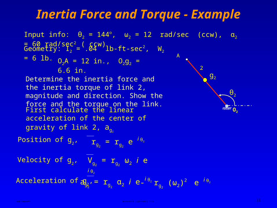
Inertia Force and Torque - Example
O2
2
A
Input info: θ2 = 144o, ω2 = 12 rad/sec (ccw), α2 = 60 rad/sec2 ( ccw)
Geometry: I2 = .04 lb-ft-sec2, W2 = 6 lb.
O2A = 12 in., O2g2 = 6.6 in.
g2Determine the inertia force and the inertia torque of link 2, magnitude and direction. Show the force and the torque on the link.
First calculate the linear acceleration of the center of gravity of link 2, ag2
Velocity of g2, Vg2
= rg2 ω2 i e i θ2
Acceleration of g2, ag
2 = rg
2 α2 i e i θ2 - rg2
(ω2)2 e i θ2
rg2 = rg2
e i θ2Position of g2,
θ2

Ken Youssefi Mechanical Engineering Dept. 12
Inertia Force and Torque - Example
ag2 = rg
2 e i θ2 [ α2 i - (ω2)
2 ]
ag2 = 6.6 e i (144) [ 60 i - (12)2 ]
ag2 = 6.6 [ cos(144) + i sin(144) ] (60 i – 144)
ag2 = 536.1 – 879 i ag2
= √ (536.1)2 + (879)2 = 1029.6 in/sec2
β2 = tan-1(-879/536.1) = -58.62
O2
2
A
g2
ag2
-58.62
Inertia force of link 2 = FI 2 = m2 ag2
FI 2 = (6/386)(1029.6) = 16 lb
h2 =I2 α2 FI 2
.04x12x60=
16= 1.8 “
TI 2 = FI 2 x h2 = 16 x 1.8 = 28.8 in-lb

Ken Youssefi Mechanical Engineering Dept. 13
Inertia Force and Torque - Example
The inertia force is in the opposite direction of the acceleration of the center of gravity
A
O2
g2
ag2
-58.62
h2
FI 2
Inertia force an torque acting on link 2
O2
A
g2
FI 2 = 16
α2
180 – 58.62 = 121.38
TI2 = 28.8
O2
A
g2
ag2
-58.62
h2
FI 2
α2
The inertia torque is in the opposite direction of α2

Ken Youssefi Mechanical Engineering Dept. 14
Force Analysis – Analytical, Matrix Method
g2
3α3 g3
g4
ag3
ag2
A
B
O2O4
24
α2 α4
ag4
Four bar mechanism
FI4
FI3
Link 3 Link 4
FI 3 = m3 ag3
FI 4 = m4 ag4
FI2
FI 2 = m2 ag2
Link 2
Inertia force
Inertia torque TI 2 = FI 2 h2 TI 3 = FI 3 h3 TI 4 = FI 4 h4
ccwcwcw
h2
h3 h4
Torque arm h2 = (I2α2)/FI2 h3 = (I3α3)/FI3 h4 = (I4α4)/FI4

Ken Youssefi Mechanical Engineering Dept. 15
Force Analysis – Analytical, Matrix Method
g2
3α3
g3g4
A
B
O2O4
24
α2 α4
FI2
FI4
FI3 TI4
TI3
TI2
T2
Show all inertia forces and torques on the four bar mechanism
Show all external and gravitational forces, location and magnitude of force P is given.
P
W4
W3
W2

Ken Youssefi Mechanical Engineering Dept. 16
Force Analysis – Analytical, Matrix Method
g2
A
O2
2
FI2
TI2
T2
W2
(FI2)y
(FI2)x
Ax
Ay
O2x
O2y
Free body diagram of link 2. Assume the direction of forces at joints A and O2
O2A = r2, O2g2 = rg2
θ2- Ax (r2 – rg
2
)sinθ2 + Ay (r2 – rg2
)cosθ2
+ O2x (rg2
)sinθ2 – O2y (rg2
)cosθ2 + T2 – TI2 = 0
(3)
∑ Mg= 0
Ay + O2y + (FI2)y - W2 = 0 (2)
∑ Fy = 0
Ax + O2x + (FI2)x = 0 (1)
∑ Fx = 0
- Ax C1 + Ay C2 + O2x C3 – O2y C4 + T2 – TI2 = 0

Ken Youssefi Mechanical Engineering Dept. 17
Force Analysis – Analytical, Matrix Method
3
g3
AB
FI3
TI3
W3
(FI3)y
(FI3)x
θ3
AB = r3, Ag3 = rg3
Ax
Ay
By
Bx
Free body diagram of link 3. Direction of the force at A has to be opposite of the direction assumed on link 2. Assume the direction of the force at joint B.
- Ax + Bx - (FI3)x = 0 (4)
∑ Fx = 0
- Ay + By - (FI3)y - W3 = 0 (5)
∑ Fy = 0
- Bx (r3 – rg3)sinθ3 + By (r3 – rg
3
)cosθ3
- Ax (rg3)sinθ3 + Ay (rg
3)cosθ3 - TI3 = 0
(6)
∑ Mg= 0

Ken Youssefi Mechanical Engineering Dept. 18
Force Analysis – Analytical, Matrix Method
g4
B
O4
4
FI4
TI4
P
W4
Free body diagram of link 4. Direction of the force at B has to be opposite of the direction assumed on link 3. Assume the direction of the force at joint O4.
O4x
O4y
By
Bx
O4B = r4, O4g4 = rg4
θ4
(FI4)x
(FI4)y
+ O4x - Bx - (FI4)x + P = 0 (7)
∑ Fx = 0
- O4y - By + (FI4)y - W4 = 0 (8)
∑ Fy = 0
Bx (r4 – rg4)sinθ4 + By (r4 – rg
4)cosθ4
+ O4x (rg4)sinθ4 - O4y (rg
4)cosθ4 + TI4 - pd= 0
(9)
∑ Mg= 0
d
d = (O4C - rg4 )sin θ4
C

Ken Youssefi Mechanical Engineering Dept. 19
Force Analysis – Analytical, Matrix MethodNine equations nine unknowns; Ax, Ay, Bx, By, O2x, O2y, O4x, O4y and T2.
Ax- (FI2)x1 0 00 0010 0
Ax + O2x = - (FI2)x (1)
Ay - (FI2)y + W20 1 00 0100 0
Ay + O2y = - (FI2)y + W2 (2)
Bx
(3)- Ax C1 + Ay C2 + O2x C3 – O2y C4 = - T2 + TI2
-C1 C2 10 0-C4C30 0 + TI2
Coefficient matrixUnknown vector
Constant vector
By
O2x
O4x
O2y
O4y
T2
- 1 0 01 0000 0 (FI3)x
0 -1 00 0001 0 (FI3)y + W3
-C7 C8 0-C5 000C6 0 TI3
0 0 0-1 0000 0
0 0 00 000-1 -1
0 0 0C9 C1100C10 -C12
(FI4)x - P
- (FI4)y + W4
Pd - TI4
=