Embed Size (px)
Citation preview
Copyr igh t S taco Sys tems , Inc . 2010
The Information and design disclosed herein was originated by and is the property of STACO SYSTEMS, INC. STACO SYSTEMS, INC. reserves all patent, proprietary, design, manufacturing, reproduction, use and sale rights thereto, and to any article disclosed therein, except to the extent rights are expressly granted to others. The foregoing does not apply to vendor proprietary parts.
KC-007 SCD
SHEET 1 OF 8
KC
-007 SC
D1.1
7 Morgan, Irvine CA 92618
PHONE: (877) 782-2648
FAX: (949) 297-8703
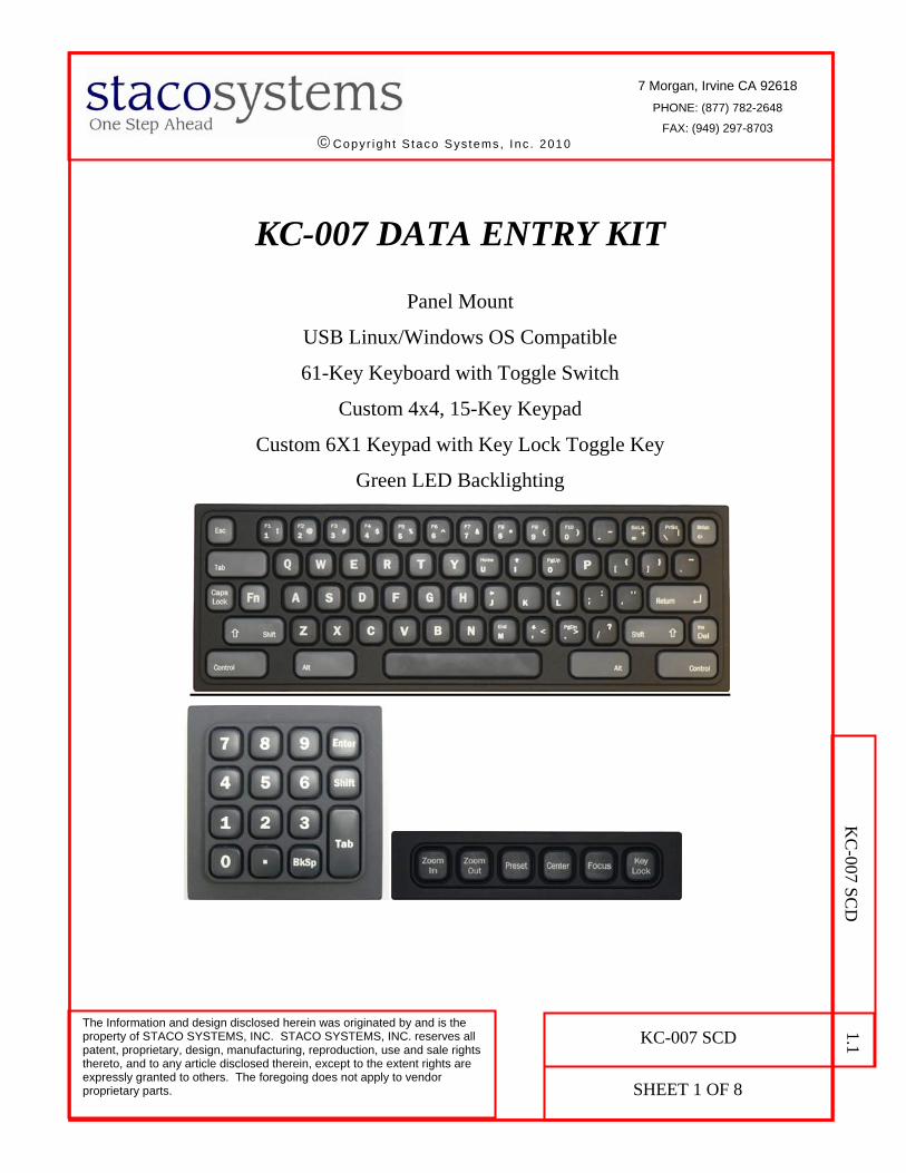
KC-007 DATA ENTRY KIT
Panel Mount
USB Linux/Windows OS Compatible
61-Key Keyboard with Toggle Switch
Custom 4x4, 15-Key Keypad
Custom 6X1 Keypad with Key Lock Toggle Key
Green LED Backlighting

CAGE CODE:
12522
DRAWING NO.
KC-007 SCD
REV. 1.1
SHT.
2
Revision Log
Rev. E. R. No. Revised By Checked By Approved By Rel. Date
1.0 41638 F. TU D. WANG J. YEH 09/02/2010
1.1 42249
TABLE OF CONTENTS
1.0 PRODUCT SPECIFICATIONS OVERVIEW .....................................................................3
2.0 PRODUCT INFORMATION ..............................................................................................4
3.0 MECHANICAL SPECIFICATIONS ...................................................................................4
3.1 M741 KEYBOARD OUTLINE DIMENSIONS .........................................................................4 3.2 M4/0001 15-KEY KEYPAD OUTLINE DIMENSIONS ...........................................................5 3.3 M2/0461 6X1 KEYPAD OUTLINE DIMENSIONS .................................................................5 3.4 PANEL CUTOUT AND MOUNTING APPLICATION ................................................................6
4.0 INTERFACE CONNECTIONS ...........................................................................................6
4.1 KEYBOARD AND KEYPAD CONNECTION............................................................................6 4.2 USB CABLE CONNECTION ................................................................................................7
5.0 LED BACKLIGHTING AND SPECIAL FUNCTION TOGGLE KEYS ...........................8
5.1 LED BACKLIGHTING ........................................................................................................8 5.2 SPECIAL FUNCTION TOGGLE KEYS ...................................................................................8
6.0 PART NUMBER INFORMATION .....................................................................................8
NOTE: KC-007 Data Entry Kit is based on Staco’s existing mechanical design of the M71 keyboard and M2 keypad products. The PCBs used for the keypad matrix and firmware controller have been re-designed with up-to-date electronics. The separate power supply and cable for backlighting in M71 are no longer needed as the power for the whole Data Entry Kit is supplied by the standard USB 5V pin. The construction of the rubber keypad, plastic keycaps, and mounting screws are still the same as the M71 and M2. The environmental specifications, excluding the temperature spec, are listed here based on the similarity of mechanical construction with M71 and M2.
CAGE CODE:
12522
DRAWING NO.
KC-007 SCD
REV.
1.1
SHT.
3
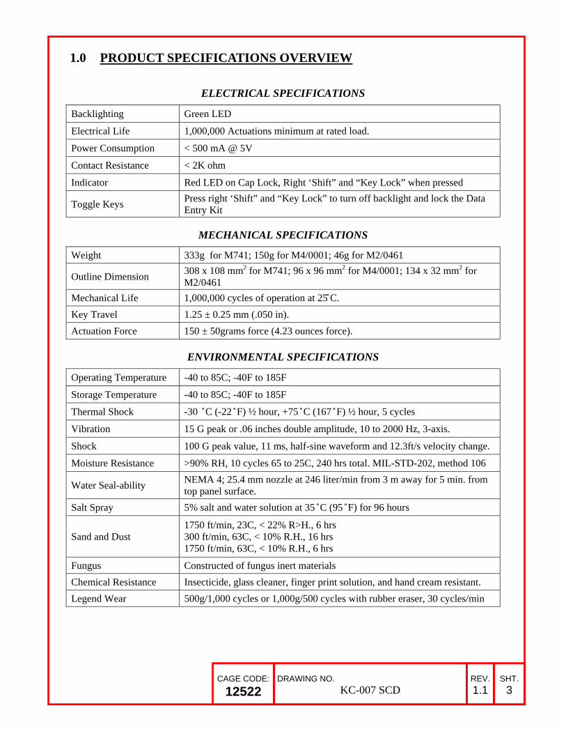
1.0 PRODUCT SPECIFICATIONS OVERVIEW
ELECTRICAL SPECIFICATIONS
Backlighting Green LED
Electrical Life 1,000,000 Actuations minimum at rated load.
Power Consumption < 500 mA @ 5V
Contact Resistance < 2K ohm
Indicator Red LED on Cap Lock, Right ‘Shift” and “Key Lock” when pressed
Toggle Keys Press right ‘Shift” and “Key Lock” to turn off backlight and lock the Data Entry Kit
MECHANICAL SPECIFICATIONS
Weight 333g for M741; 150g for M4/0001; 46g for M2/0461
Outline Dimension 308 x 108 mm2 for M741; 96 x 96 mm2 for M4/0001; 134 x 32 mm2 for M2/0461
Mechanical Life 1,000,000 cycles of operation at 25 ̊C.
Key Travel 1.25 ± 0.25 mm (.050 in).
Actuation Force 150 ± 50grams force (4.23 ounces force).
ENVIRONMENTAL SPECIFICATIONS
Operating Temperature -40 to 85C; -40F to 185F
Storage Temperature -40 to 85C; -40F to 185F
Thermal Shock -30 ̊C (-22 ̊F) ½ hour, +75 ̊C (167 ̊F) ½ hour, 5 cycles
Vibration 15 G peak or .06 inches double amplitude, 10 to 2000 Hz, 3-axis.
Shock 100 G peak value, 11 ms, half-sine waveform and 12.3ft/s velocity change.
Moisture Resistance >90% RH, 10 cycles 65 to 25C, 240 hrs total. MIL-STD-202, method 106
Water Seal-ability NEMA 4; 25.4 mm nozzle at 246 liter/min from 3 m away for 5 min. from top panel surface.
Salt Spray 5% salt and water solution at 35 ̊C (95 ̊F) for 96 hours
Sand and Dust 1750 ft/min, 23C, < 22% R>H., 6 hrs 300 ft/min, 63C, < 10% R.H., 16 hrs 1750 ft/min, 63C, < 10% R.H., 6 hrs
Fungus Constructed of fungus inert materials
Chemical Resistance Insecticide, glass cleaner, finger print solution, and hand cream resistant.
Legend Wear 500g/1,000 cycles or 1,000g/500 cycles with rubber eraser, 30 cycles/min

CAGE CODE:
12522
DRAWING NO.
KC-007 SCD
REV.
1.1
SHT.
4
2.0 PRODUCT INFORMATION
The KC-007 Data Entry Kit is consisted of the following subassembly that includes 61-key keyboard, 15-key and 6x1 keypads, plus the interconnecting cables.
3.0 MECHANICAL SPECIFICATIONS
3.1 M741 Keyboard Outline Dimensions The panel mount keyboard outline dimensions are shown in Fig. 1. The maximum height
of the controller board on back side of the keyboard is 9 mm.
Fig. 1: M741 Keyboard Outline Dimensions (in millimeters)
Part Number Description QTY.
M4/0001 Custom SQ. 4x4, 15-Key Keypad Assy with Legends 1
M741 Custom 61-Key Keyboard, USB, Backlit, With Cap Lock Toggle Key 1
M2/0461 Custom 6X1 Keypad With Key Lock Toggle Key, 1
129016-001 Cable For 4X4 and 6X1 Keypads To 61-Key LED Board (155 mm) 5
129016-002 Cable For 6X1 Keypad CON1 To 61-Key LED Board (165 mm) 1
“Shift” key to be used with TK2
key

CAGE CODE:
12522
DRAWING NO.
KC-007 SCD
REV.
1.1
SHT.
5
3.2 M4/0001 15-Key Keypad Outline Dimensions The panel mount 15-key keypad outline dimensions are shown in Fig. 2. The maximum
component height on back side of the keypad is 1.45 mm.
Fig 2: M4/0001 15-Key Keypad Outline Dimensions (in millimeters)
3.3 M2/0461 6x1 Keypad Outline Dimensions The panel mount 6x1 keypad outline dimensions are shown in Fig. 3. The maximum
component height on back side of the keypad is 1.44 mm.
Fig. 3: M2/0461 6x1 Keypad Outline Dimensions (in millimeters)
TK2

CAGE CODE:
12522
DRAWING NO.
KC-007 SCD
REV.
1.1
SHT.
6
3.4 Panel Cutout and Mounting Application Refer to the following Staco documents for the details of the recommendation of panel
cutout and mounting instruction.
“SERIES M71 CODED” SCD for M741 keyboard “SERIES M2 & M15 CODED” SCD for M4/0001 and M2/0461 keypads
4.0 INTERFACE CONNECTIONS
4.1 Keyboard and Keypad Connection
The keyboard and keypads in the KC-007 Data Entry Kit are connected with 6 cables as
illustrated in Fig. 4. Three cables of P/N 129016-001 (155 mm) are connected from the keyboard to the 15-key keypad. Two of the same cable (P/N 129016-001) and the other cable of P/N 129016-002 (165 mm) are used to connect the keyboard to the 6x1 keypad. See Fig. 5 for the photo of cable connections.
Fig. 4: KC-007 Cable Connections Between Keyboard and Keypads
Fig. 5: Photo of KC-007 Cable Connections

CAGE CODE:
12522
DRAWING NO.
KC-007 SCD
REV.
1.1
SHT.
7
4.2 USB Cable Connection
After all six cables are connected, the KC-007 Data Entry Kit is connected to a computer
through a single USB cable (not provided by Staco) as shown in Fig. 6. The cable is plugged into a mating connector on the controller board mounted to the LED PCB of the M741 keyboard. The manufacturer part number of the connector used for the USB cable is 87439-0500 from MOLEX with mechanical details described in Fig. 7.
Fig.6: KC-007 Connected To Computer Through a USB Cable

CAGE CODE:
12522
DRAWING NO.
KC-007 SCD
REV.
1.1
SHT.
8
Fig. 7: 87439-0500 MOLEX Connector For USB Cable
5.0 LED BACKLIGHTING AND SPECIAL FUNCTION TOGGLE KEYS
5.1 LED Backlighting The keyboard is equipped with “green” LED backlight for all keys and will be turned ON when connected with the USB cable. The Cap Lock has “red” backlight when pressed.
5.2 Special Function Toggle Keys The Data Entry Kit can be locked AND turned off the backlight by pressing two keys – the right “SHIFT” key on the 61-key keyboard (see Fig. 1) and the “Key Lock” TK2 key on the 6x1 keypad (see Fig. 3). In this state, the Data Entry Kit is locked and the backlight of the two keys (right “SHIFT” and “Key Lock” ) turns to red. When these two keys are pressed again, the Data Entry Kit returns to normal operating state.
6.0 PART NUMBER INFORMATION The color of the all rubber keypads and keys is black with the following exception: the control keys on the 61-key keyboard are gray color as shown in Fig. 1. The part number and description of the Data Entry Kit for ordering information is described in the following.
Part Number Production Description
KC-007 DATA ENTRY KIT, 61 KEY KEYBOARD WITH TOGGLE SWITCH, MODIFIED 4X4, 6X1 KEYPAD WITH TOGGLE KEY