Embed Size (px)
Citation preview
Kiwiprops™
K3 Kiwiprops™ Assembly
Kiwiprops™
BO
SS
AS
SE
MB
LY -
ST
AG
E I
Version V6 Dated: 30th December 2016

1: TABLE OF CONTENTS
1: TABLE OF CONTENTS
2: BILL OF MATERIALS 3: GENERAL 4: BOSS SELECTION CRITERIA
5: PREPARING NOSE CONE 6: FITTING THE TRIPOD
7: REGISTRATION BOSS AND BLADE CARRIER 8: INSTALLING THE REVERSING ROLLERS 9: SELECTING THE SPRING 10: FINAL BOSS ASSEMBLY – TOOLING REQUIREMENTS 11: FINAL BOSS ASSEMBLY 12: SUMMARY OF OPERATIONS 13: ROLLER REGISTRATIONS
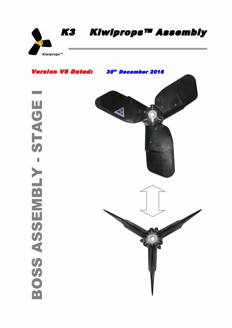
2: BILL OF MATERIALS
• A Boss with the correct Spline or Shaft size
• A SS Spring - Handed Opposite to the Prop • A Blade Carrier which is common to all propellers • A Nose Cone which will be either Saildrive or Shaft
Lombardini Saildrive Units have a smaller OD .. see Drawings Volvo Saildrives have an extended Nose Cone .. Yanmar Saildrives have Nose Cones specific to SD20-50 and new SD60’s
• A Nut to match the mounting from the schematic above
• A Tripod casting finished Left or Right Hand provides the pitch stops
• Vesconite™ Internal Boss / Blade Carrier Sleeve
• Vesconite™ Aft Washer – Boss / Blade Carrier Rear thrust and seal
• Three blades of the required diameter
• Three Reversing Rollers with 316 SS ¼” UNC or BSW Attachment Screw
Current Reverse Screws are M8 x 1.25 – Circle(s) on upper face for M8 ID
• Two Locking Grub Screws M8 x 10 mm for the Nut in SS 316
• Three pitch adjustment screws M8 x 30 mm in SS 316
• Three ½” x # 4 SS Pozi Self tapping screws
• Three ¼” x 25 mm Titanium Threaded Blade Retention Pins with Caps
• Four SS 316 1 ½” x ¼” UNC Cap Screws to attach the nose cone
• Loctite™ for the reversing rollers
• 3M 5200 / SIKA Equivalent for the nose cones
• CALTX DELO ESI Grease or Marine quality equivalent
• Appropriate Hand Tools, Turpentine & Cleaning rags etc

3: GENERAL The following Chapters describe the Assembly of the various sub- components that go to make up a Boss Assembly which is held in stock by mounting type. Only when a specific Customer Order is received are the Bosses then numbered and the appropriate blade set mounted and the Pitch set to the specific order requirements. The actions described below relate to one specific assembly. Normally these would be assembled in small batches to make it simpler and easier to remember the assembly routines.
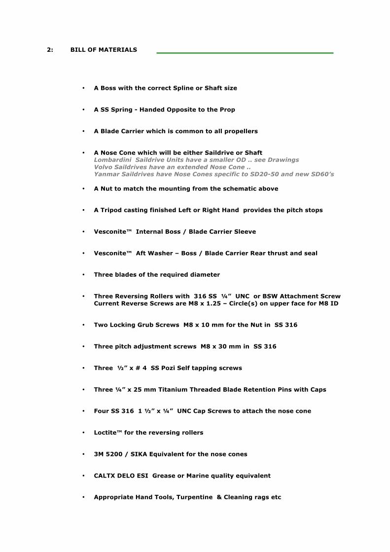
4: BOSS SELECTION CRITERIA - IMPERIAL
1 ¼” Sh
NZ
1 ¼” SAE 1:16 Boss = 2.625” Mount 0.625”down taper Nut = ¾” or 7/8” UNC Key = 5/16” mod to 0.285”
US SAE
1 ¼” SAE 1:16 Boss = 3.125” Mount 0.625”down taper Nut = 7/8” UNC Key = 5/16” mod to 0.285
No
n S
tan
da
rd
1 ” Sh
US SAE
1” SAE 1:16 Boss = 3.000” Nut = ¾” UNC Keyway = ¼”
NZ
1” SAE 1:16 Boss = 2.500” Nut = 5/8” UNC, or ¾” Keyway = ¼”
No
n S
tan
da
rd
SAE 16/32 Spline for 28 mm OD Shaft Boss = 3.125” long, Nut ex SS 316 Left Handed with thread M16 @ 2.00 mm Pitch NB: YANMAR SD40 & Later has M20 @ 2.00 mm Pitch Slinger ~25 mm long must be mounted on shaft
Sail Dri
Sm
all N
AN
NI’
s a
re
No
n S
tan
da
rd
1 ” Sh
US SAE
1.125” SAE 1:16 Boss = 3.375” Mount 0.250” down taper Nut = ¾” UNC – LESS 0.125” Keyway = ¼”
NZ
1.125” SAE 1:16 Boss = 3.125” Rare in NZ Mount 0.250” down taper Nut = 5/8” UNC, or ¾” Keyway = ¼”
No
n S
tan
da
rd
1 1/8” Shaf
Metric Shaft .. See Below
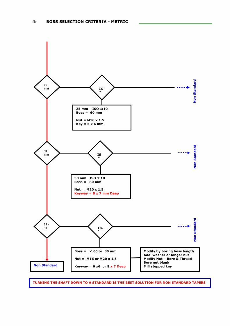
4: BOSS SELECTION CRITERIA - METRIC
ISO
1 ” Sh
ISO
30 mm ISO 1:10 Boss = 80 mm Nut = M20 x 1.5 Keyway = 8 x 7 mm Deep
No
n S
tan
da
rd
30 mm Shaf
25 mm Shaf
25 mm ISO 1:10 Boss = 60 mm Nut = M16 x 1.5 Key = 6 x 6 mm
No
n S
tan
da
rd
Non Standard
25 - 30 Met
1:10
No
n S
tan
da
rd
Boss = < 60 or 80 mm Nut = M16 or M20 x 1.5 Keyway = 6 x6 or 8 x 7 Deep
Modify by boring boss length Add washer or longer nut Modify Nut – Bore & Thread Bore nut blank Mill stepped key
TURNING THE SHAFT DOWN TO A STANDARD IS THE BEST SOLUTION FOR NON STANDARD TAPERS
5: PREPARING NOSE CONE All propellers have either a Saildrive or Shaft Nose Cone irrespective of any other features such as shaft diameter or rotation. The Saildrive nose unit is designed to fair the body of the propeller to the larger gear casing of the Saildrive. The shaft drive nose unit is designed to fair the body of the propeller down to the much smaller shaft dimensions. NB: LOMBARDINI NOSE CONES ARE REDUCED IN OUTSIDE DIAMETER TO 3.5” – Refer Drawings In each case the nose cone performs two other critical functions which are not obvious from a cursory examination.
• First the protruding rim inside each unit fits into the groove on the boss and absorbs all the forward thrust of the propeller. It transfers this initially from the blade carrier thru the pitch stops and tripod casting thru the boss to the shaft to provide forward motion.
• Second the nose contains a hole into which one end of the torsion spring is mounted so that
it can absorb the torsion of the spring and transfer this thru the nose to the boss. It also provides the facility to preload the torsion spring and adjust the amount of tension to ensure proper operation of the propeller and ensure that the blade carrier always returns to a position which will allow the blades to feather. This it will not do unless the blade carrier is held in the neutral position with the spring.
While the external profile of these components is very different the internal dimensions and method of attachment are absolutely identical. The same comments thus apply to either unit. Once the Saildrive or Shaft choice has been made every other instruction for preparation is common.
ALL NOSE CONE UNITS UNITS ARE NOW DELIVERED PRE-SPLIT IN A GLASS REINFORCED POLYPROPYLENE COLOURED BLACK AND PAIRED TOGETHER WITH CABLE TIES TO ENSURE THE TWO COMPONENTS ARE MATCHED FROM ORIGINAL UNIT TO ELIMINATE ANY MACHINING TOLERANCES INVOLVED IN THE SPLITTING THIS ENSURES ANY MACHINING ERRORS ARE ELIMINATED UPON ASSEMBLY
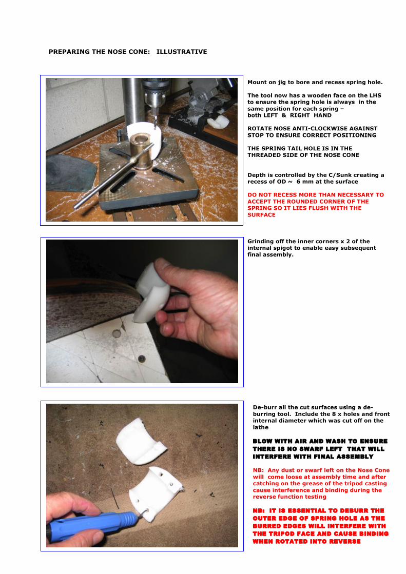
PREPARING THE NOSE CONE: ILLUSTRATIVE
Mount on jig to bore and recess spring hole. The tool now has a wooden face on the LHS to ensure the spring hole is always in the same position for each spring – both LEFT & RIGHT HAND ROTATE NOSE ANTI-CLOCKWISE AGAINST STOP TO ENSURE CORRECT POSITIONING THE SPRING TAIL HOLE IS IN THE THREADED SIDE OF THE NOSE CONE Depth is controlled by the C/Sunk creating a recess of OD ~ 6 mm at the surface DO NOT RECESS MORE THAN NECESSARY TO ACCEPT THE ROUNDED CORNER OF THE SPRING SO IT LIES FLUSH WITH THE SURFACE Grinding off the inner corners x 2 of the internal spigot to enable easy subsequent final assembly.
De-burr all the cut surfaces using a de-burring tool. Include the 8 x holes and front internal diameter which was cut off on the lathe BLOW WITH AIR AND WASH TO ENSURE THERE IS NO SWARF LEFT THAT WILL INTERFERE WITH FINAL ASSEMBLY NB: Any dust or swarf left on the Nose Cone will come loose at assembly time and after catching on the grease of the tripod casting cause interference and binding during the reverse function testing NB: IT IS ESSENTIAL TO DEBURR THE OUTER EDGE OF SPRING HOLE AS THE BURRED EDGES WILL INTERFERE WITH THE TRIPOD FACE AND CAUSE BINDING WHEN ROTATED INTO REVERSE
6: FITTING THE TRIPOD The SS316 tripod performs three separate functions for the propeller.
• First it provides stops for the pitch screws to come up against and then to transfer the forward thrust they generate onto the nose cone and thence the boss.
• Second the body of the casting takes the forward thrust from the blade carrier and transfers
that onto the nose cone and then the boss. Remember the blade carrier is free to slide down the boss.
• Thirdly it provides a cover for the spring housed inside to ensure it remains lubricated over
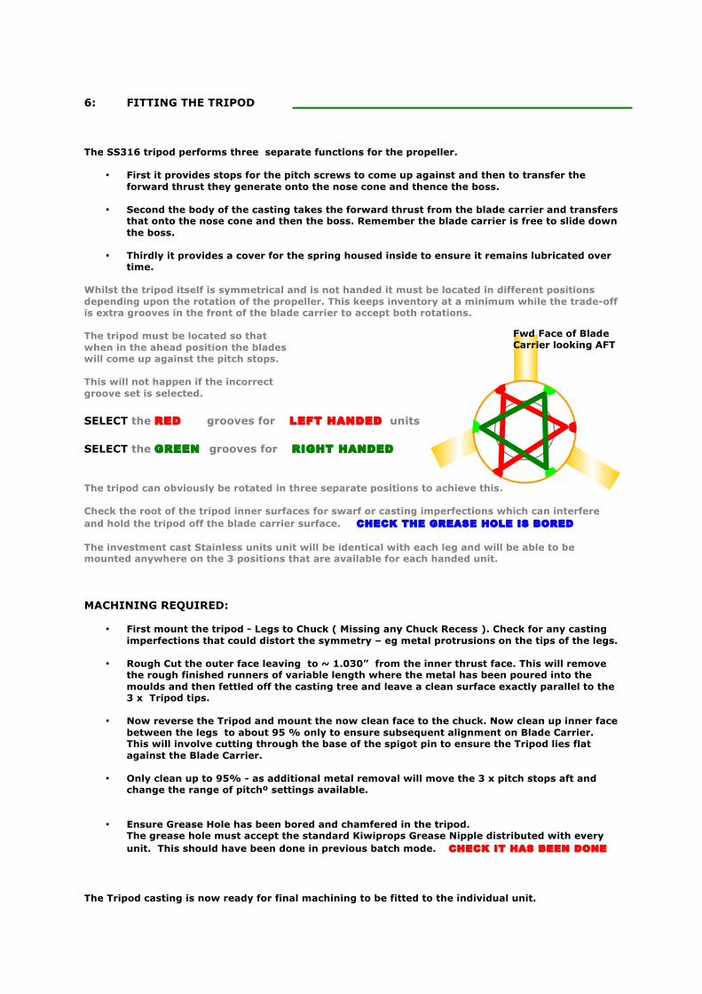
time. Whilst the tripod itself is symmetrical and is not handed it must be located in different positions depending upon the rotation of the propeller. This keeps inventory at a minimum while the trade-off is extra grooves in the front of the blade carrier to accept both rotations. The tripod must be located so that when in the ahead position the blades will come up against the pitch stops. This will not happen if the incorrect groove set is selected. SELECT the RED grooves for LEFT HANDED units SELECT the GREEN grooves for RIGHT HANDED The tripod can obviously be rotated in three separate positions to achieve this. Check the root of the tripod inner surfaces for swarf or casting imperfections which can interfere and hold the tripod off the blade carrier surface. CHECK THE GREASE HOLE IS BORED The investment cast Stainless units unit will be identical with each leg and will be able to be mounted anywhere on the 3 positions that are available for each handed unit. MACHINING REQUIRED:
• First mount the tripod - Legs to Chuck ( Missing any Chuck Recess ). Check for any casting imperfections that could distort the symmetry – eg metal protrusions on the tips of the legs.
• Rough Cut the outer face leaving to ~ 1.030” from the inner thrust face. This will remove
the rough finished runners of variable length where the metal has been poured into the moulds and then fettled off the casting tree and leave a clean surface exactly parallel to the 3 x Tripod tips.
• Now reverse the Tripod and mount the now clean face to the chuck. Now clean up inner face
between the legs to about 95 % only to ensure subsequent alignment on Blade Carrier. This will involve cutting through the base of the spigot pin to ensure the Tripod lies flat against the Blade Carrier.
• Only clean up to 95% - as additional metal removal will move the 3 x pitch stops aft and
change the range of pitchº settings available.
• Ensure Grease Hole has been bored and chamfered in the tripod. The grease hole must accept the standard Kiwiprops Grease Nipple distributed with every unit. This should have been done in previous batch mode. CHECK IT HAS BEEN DONE
The Tripod casting is now ready for final machining to be fitted to the individual unit.
Fwd Face of Blade Carrier looking AFT
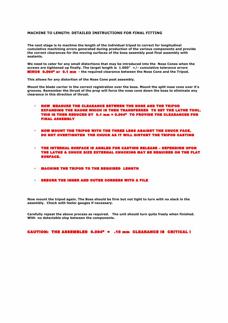
MACHINE TO LENGTH: DETAILED INSTRUCTIONS FOR FINAL FITTING The next stage is to machine the length of the individual tripod to correct for longitudinal cumulative machining errors generated during production of the various components and provide the correct clearances for the moving surfaces of the boss assembly post final assembly with sealants. We need to cater for any small distortions that may be introduced into the Nose Cones when the screws are tightened up finally. The target length is 1.000” +/- cumulative tolerance errors MINUS 0.004” or 0.1 mm - the required clearance between the Nose Cone and the Tripod. This allows for any distortion of the Nose Cone post assembly. Mount the blade carrier in the correct registration over the boss. Mount the split nose cone over it’s grooves. Remember the thrust of the prop will force the nose cone down the boss to eliminate any clearance in this direction of thrust.
• NOW MEASURE THE CLEARANCE BETWEEN THE NOSE AND THE TRIPOD EXPANDING THE GAUGE WHICH IS THEN TRANSFERRED TO SET THE LATHE TOOL. THIS IS THEN REDUCED BY 0.1 mm = 0.004” TO PROVIDE THE CLEARANCES FOR FINAL ASSEMBLY
• NOW MOUNT THE TRIPOD WITH THE THREE LEGS AGAINST THE CHUCK FACE. DO NOT OVERTIGHTEN THE CHUCK AS IT WILL DISTORT THE TRIPOD CASTING
• THE INTERNAL SURFACE IS ANGLED FOR CASTING RELEASE – DEPENDING UPON THE LATHE & CHUCK SIZE EXTERNAL CHUCKING MAY BE REQUIRED ON THE FLAT SURFACE.
• MACHINE THE TRIPOD TO THE REQUIRED LENGTH
• DEBURR THE INNER AND OUTER CORNERS WITH A FILE Now mount the tripod again. The Boss should be firm but not tight to turn with no slack in the assembly. Check with feeler gauges if necessary. Carefully repeat the above process as required. The unit should turn quite freely when finished. With no detectable slop between the components. CAUTION: THE ASSEMBLED 0.004” = .10 mm CLEARANCE IS CRITICAL !
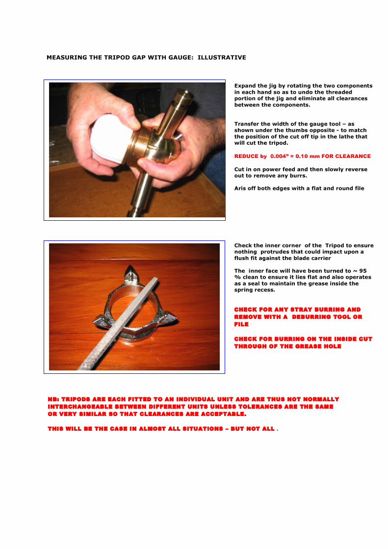
MEASURING THE TRIPOD GAP WITH GAUGE: ILLUSTRATIVE
NB: TRIPODS ARE EACH FITTED TO AN INDIVIDUAL UNIT AND ARE THUS NOT NORMALLY INTERCHANGEABLE BETWEEN DIFFERENT UNITS UNLESS TOLERANCES ARE THE SAME OR VERY SIMILAR SO THAT CLEARANCES ARE ACCEPTABLE. THIS WILL BE THE CASE IN ALMOST ALL SITUATIONS – BUT NOT ALL .
Expand the jig by rotating the two components in each hand so as to undo the threaded portion of the jig and eliminate all clearances between the components. Transfer the width of the gauge tool – as shown under the thumbs opposite - to match the position of the cut off tip in the lathe that will cut the tripod. REDUCE by 0.004” = 0.10 mm FOR CLEARANCE Cut in on power feed and then slowly reverse out to remove any burrs. Aris off both edges with a flat and round file Check the inner corner of the Tripod to ensure nothing protrudes that could impact upon a flush fit against the blade carrier The inner face will have been turned to ~ 95 % clean to ensure it lies flat and also operates as a seal to maintain the grease inside the spring recess. CHECK FOR ANY STRAY BURRING AND REMOVE WITH A DEBURRING TOOL OR FILE CHECK FOR BURRING ON THE INSIDE CUT THROUGH OF THE GREASE HOLE
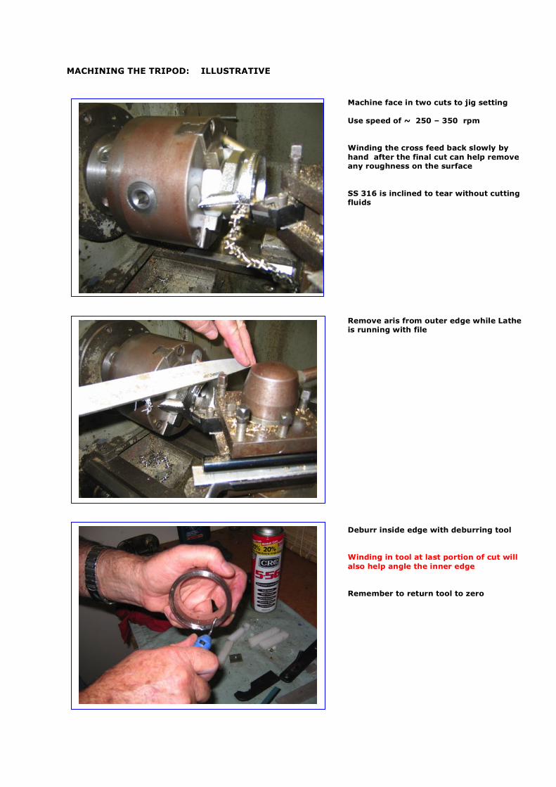
MACHINING THE TRIPOD: ILLUSTRATIVE
Machine face in two cuts to jig setting Use speed of ~ 250 – 350 rpm Winding the cross feed back slowly by hand after the final cut can help remove any roughness on the surface SS 316 is inclined to tear without cutting fluids Remove aris from outer edge while Lathe is running with file Deburr inside edge with deburring tool Winding in tool at last portion of cut will also help angle the inner edge Remember to return tool to zero
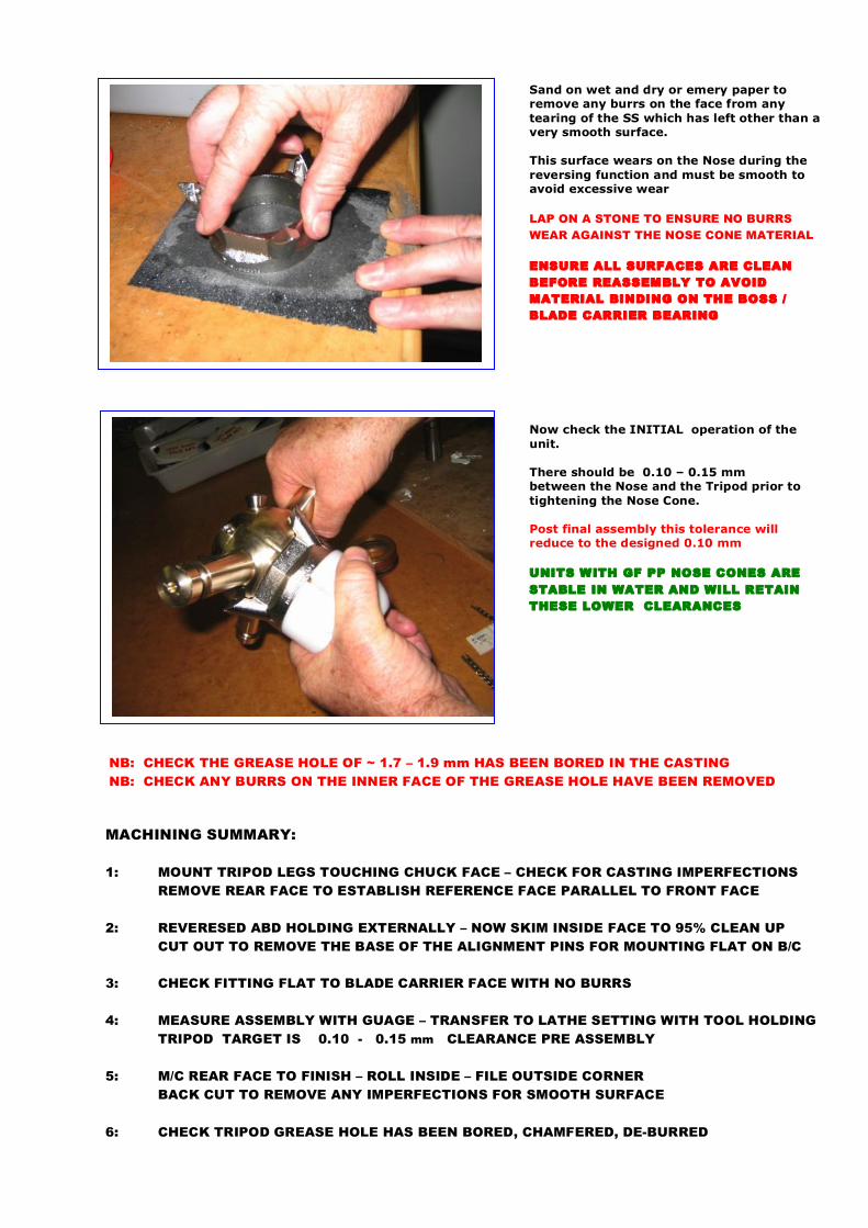
Sand on wet and dry or emery paper to remove any burrs on the face from any tearing of the SS which has left other than a very smooth surface. This surface wears on the Nose during the reversing function and must be smooth to avoid excessive wear LAP ON A STONE TO ENSURE NO BURRS WEAR AGAINST THE NOSE CONE MATERIAL ENSURE ALL SURFACES ARE CLEAN BEFORE REASSEMBLY TO AVOID MATERIAL BINDING ON THE BOSS / BLADE CARRIER BEARING Now check the INITIAL operation of the unit. There should be 0.10 – 0.15 mm between the Nose and the Tripod prior to tightening the Nose Cone. Post final assembly this tolerance will reduce to the designed 0.10 mm UNITS WITH GF PP NOSE CONES ARE STABLE IN WATER AND WILL RETAIN THESE LOWER CLEARANCES
NB: CHECK THE GREASE HOLE OF ~ 1.7 – 1.9 mm HAS BEEN BORED IN THE CASTING NB: CHECK ANY BURRS ON THE INNER FACE OF THE GREASE HOLE HAVE BEEN REMOVED
MACHINING SUMMARY: 1: MOUNT TRIPOD LEGS TOUCHING CHUCK FACE – CHECK FOR CASTING IMPERFECTIONS REMOVE REAR FACE TO ESTABLISH REFERENCE FACE PARALLEL TO FRONT FACE 2: REVERESED ABD HOLDING EXTERNALLY – NOW SKIM INSIDE FACE TO 95% CLEAN UP CUT OUT TO REMOVE THE BASE OF THE ALIGNMENT PINS FOR MOUNTING FLAT ON B/C 3: CHECK FITTING FLAT TO BLADE CARRIER FACE WITH NO BURRS 4: MEASURE ASSEMBLY WITH GUAGE – TRANSFER TO LATHE SETTING WITH TOOL HOLDING
TRIPOD TARGET IS 0.10 - 0.15 mm CLEARANCE PRE ASSEMBLY 5: M/C REAR FACE TO FINISH – ROLL INSIDE – FILE OUTSIDE CORNER BACK CUT TO REMOVE ANY IMPERFECTIONS FOR SMOOTH SURFACE 6: CHECK TRIPOD GREASE HOLE HAS BEEN BORED, CHAMFERED, DE-BURRED
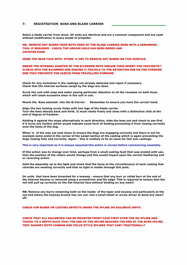
7: REGISTRATION BOSS AND BLADE CARRIER Select a blade carrier from stock. All units are identical and are a common component and are used without modification in every model of propeller. NB: REMOVE ANY BURRS FROM BOTH ENDS OF THE BLADE CARRIER BORE WITH A DEBURRING TOOL IF REQUIRED – CHECK THE GREASE HOLE HAS BEEN BORED AND COUNTER SUNK HONE THE REAR FACE WITH STONE & CRC TO REMOVE ANY BURRS ON THIS SURFACE SMEAR THE INTERNAL DIAMTER OF THE B/CARRIER WITH GREASE THEN INSERT THE VESCONITE™ SLEEVE INTO THE B/CARRIER AND ENSURE IT TRAVELS TO THE RETENTION RIM ON THE FORWARD END THAT PREVENTS THE SLEEVE FROM TRAVELLING FORWARD Check for any inclusions in the castings not already detected and reject if necessary. Check that the internal surfaces swept by the dogs are clean. Scrub the unit with soap and water paying particular attention to all the recesses on both faces which will cause excessive wear in the unit in use. Mount the Boss selected into the B/Carrier. Remember to ensure you have the correct hand. Align the two locking screw holes with two legs of the blade carrier. Turn the boss sharply back and forth. It must rotate freely and close with a distinctive click at the end of degree of freedom. Holding it against the stops alternatively in each direction, slide the boss out and check to see first if it turns any further which would indicate some form of binding preventing it from closing correctly onto the faces of the dog. When ¾ of the way out look down to ensure the dogs are engaging correctly and there is not for example some metal in the corner of the swept section of the casting which is again preventing the dogs closing fully and correctly. Again – this is unlikely to be an issue for lost wax castings. This is very important as it is always assumed this action is correct before commencing assembly. If this action was to change over time, perhaps from a small casting fault that was eroded with use, then the position of the rollers would change and this would impact upon the correct feathering and or reversing action. Hold the assembly up to the light and check that the faces at the circumference of each casting that coincide are meeting correctly and that no light is visible through this joint. On units that have been broached for a keyway - ensure that any burr or rolled burr at the end of the internal keyway is removed using a screwdriver and file edge. This is required to ensure that the nut will pull up correctly on the flat internal face without binding on any swarf. NB: Remove any burrs remaining both on the inside of the taper and keyway and particularly at the nut end where the keyway broach has run out. Use a small chisel or screw driver to bend any swarf off. CHECK FOR BURRS OR CASTING DEFECTS INSIDE THE SPLINE ON SAILDRIVE UNITS. CHECK THAT ALL SAILDRIVES CAN BE MOUNTED FRONT FACE FIRST OVER THE GO SPLINE AND TRAVEL TO A DEPTH SUCH THAT THE END OF THE SPLINE REACHES THE END OF THE BOSS SPLINE. TEST AGAINST BOTH YANMAR AND VOLVO STYLE SPLINES THAT VARY FRACTIONALLY
This picture to the right shows how when the Blade Carrier is held and the boss rotated to a drive position – in this case in a LEFT HANDED or Anticlockwise direction - then it is essential for the two holes bored for the M8 locking screws to align with the legs on the Blade Carrier. As there are 2 internal dogs and three legs there are two different registration positions that the Boss can adopt relative to the position of the Blade Carrier All perspectives are from AFT facing FORWARD when referencing rotation Note the boss being rotated in a LEFT HANDED direction
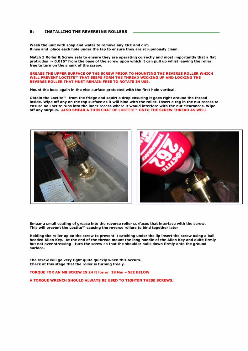
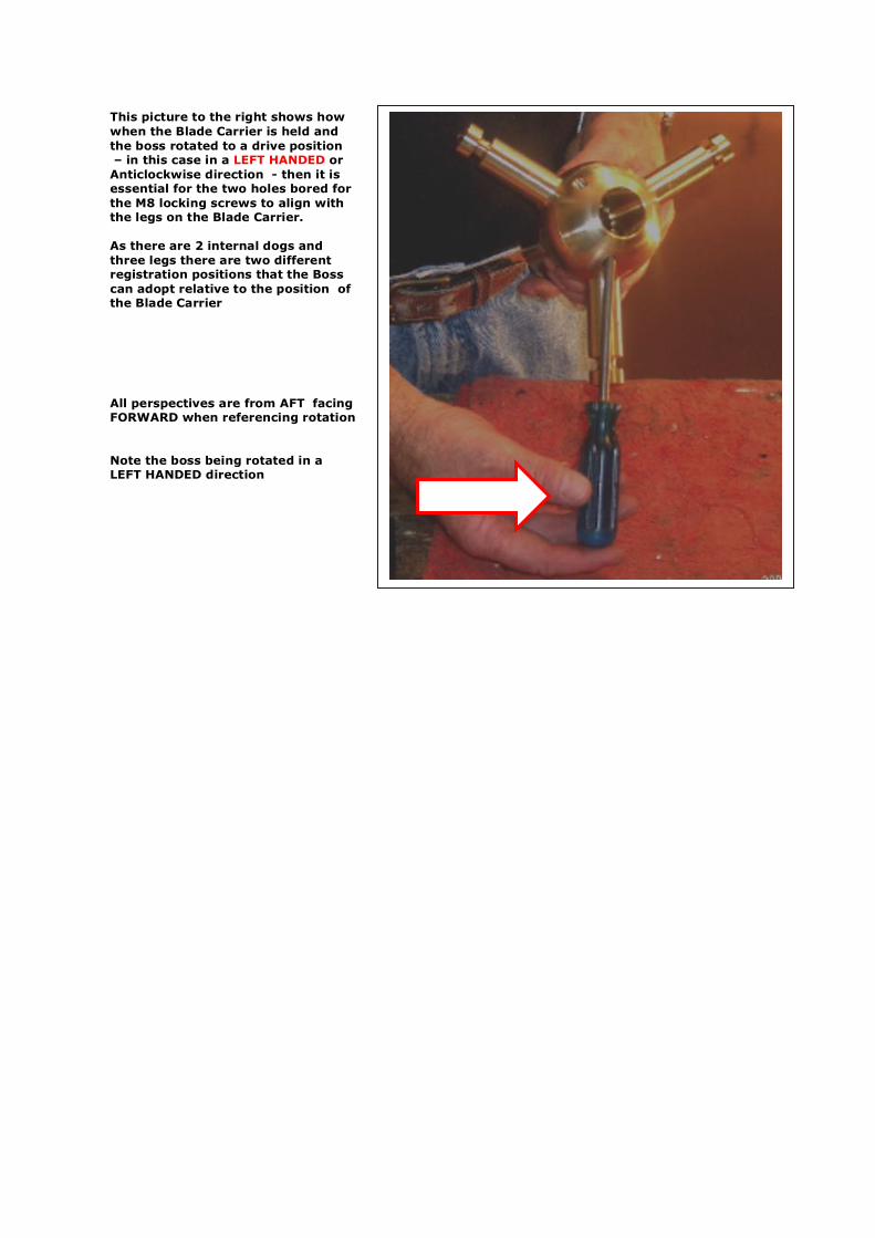
8: INSTALLING THE REVERSING ROLLERS Wash the unit with soap and water to remove any CRC and dirt. Rinse and place each hole under the tap to ensure they are scrupulously clean. Match 3 Roller & Screw sets to ensure they are operating correctly and most importantly that a flat protrudes ~ 0.015” from the base of the screw upon which it can pull up whist leaving the roller free to turn on the shank of the screw. GREASE THE UPPER SURFACE OF THE SCREW PRIOR TO MOUNTING THE REVERSE ROLLER WHICH WILL PREVENT LOCTITE™ THAT SEEPS FORM THE THREAD WICKING UP AND LOCKING THE REVERSE ROLLER THAT MUST REMAIN FREE TO ROTATE IN USE. Mount the boss again in the vice surface protected with the first hole vertical. Obtain the Loctite™ from the fridge and squirt a drop ensuring it goes right around the thread inside. Wipe off any on the top surface as it will bind with the roller. Insert a rag in the nut recess to ensure no Loctite runs into the inner recess where it would interfere with the nut clearances. Wipe off any surplus. ALSO SMEAR A THIN COAT OF LOCTITE™ ONTO THE SCREW THREAD AS WELL Smear a small coating of grease into the reverse roller surfaces that interface with the screw. This will prevent the Loctite™ causing the reverse rollers to bind together later Holding the roller up on the screw to prevent it catching under the lip insert the screw using a ball headed Allen Key. At the end of the thread mount the long handle of the Allen Key and quite firmly but not over stressing - turn the screw so that the shoulder pulls down firmly onto the ground surface. The screw will go very tight quite quickly when this occurs. Check at this stage that the roller is turning freely. TORQUE FOR AN M8 SCREW IS 24 ft lbs or 18 Nm – SEE BELOW A TORQUE WRENCH SHOULD ALWAYS BE USED TO TIGHTEN THESE SCREWS.
MOUNTING REVERSE SCREWS & ROLLERS: ILLUSTRATIVE
TORQUE TO 18 Nm ( 24 ft lbs ) with a TORQUE WRENCH - DO NOT TIGHTEN WITHOUT A TORQUE WRENCH CHECK THE CONTACT SURFACES WITH THE BLADE CARRIER VERY CAREFULLY TO ENSURE NO BURRS REMOVE WITH A FINE RIFFLER FILE IF REQUIRED. STORE SO NO DAMAGE CAN RESULT TO THE BOSS UNTIL FINAL ASSEMBLY.
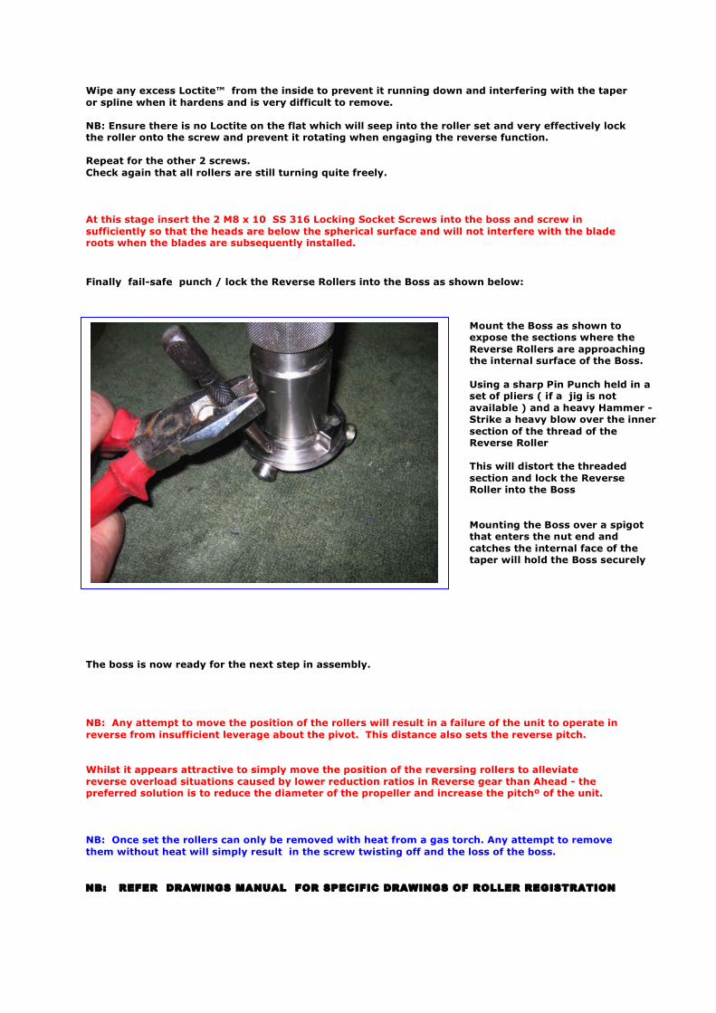
Wipe any excess Loctite™ from the inside to prevent it running down and interfering with the taper or spline when it hardens and is very difficult to remove. NB: Ensure there is no Loctite on the flat which will seep into the roller set and very effectively lock the roller onto the screw and prevent it rotating when engaging the reverse function. Repeat for the other 2 screws. Check again that all rollers are still turning quite freely. At this stage insert the 2 M8 x 10 SS 316 Locking Socket Screws into the boss and screw in sufficiently so that the heads are below the spherical surface and will not interfere with the blade roots when the blades are subsequently installed. Finally fail-safe punch / lock the Reverse Rollers into the Boss as shown below: The boss is now ready for the next step in assembly. NB: Any attempt to move the position of the rollers will result in a failure of the unit to operate in reverse from insufficient leverage about the pivot. This distance also sets the reverse pitch. Whilst it appears attractive to simply move the position of the reversing rollers to alleviate reverse overload situations caused by lower reduction ratios in Reverse gear than Ahead - the preferred solution is to reduce the diameter of the propeller and increase the pitchº of the unit. NB: Once set the rollers can only be removed with heat from a gas torch. Any attempt to remove them without heat will simply result in the screw twisting off and the loss of the boss. NB: REFER DRAWINGS MANUAL FOR SPECIFIC DRAWINGS OF ROLLER REGISTRATION
Mount the Boss as shown to expose the sections where the Reverse Rollers are approaching the internal surface of the Boss. Using a sharp Pin Punch held in a set of pliers ( if a jig is not available ) and a heavy Hammer - Strike a heavy blow over the inner section of the thread of the Reverse Roller This will distort the threaded section and lock the Reverse Roller into the Boss Mounting the Boss over a spigot that enters the nut end and catches the internal face of the taper will hold the Boss securely
9: SELECTING THE SPRING
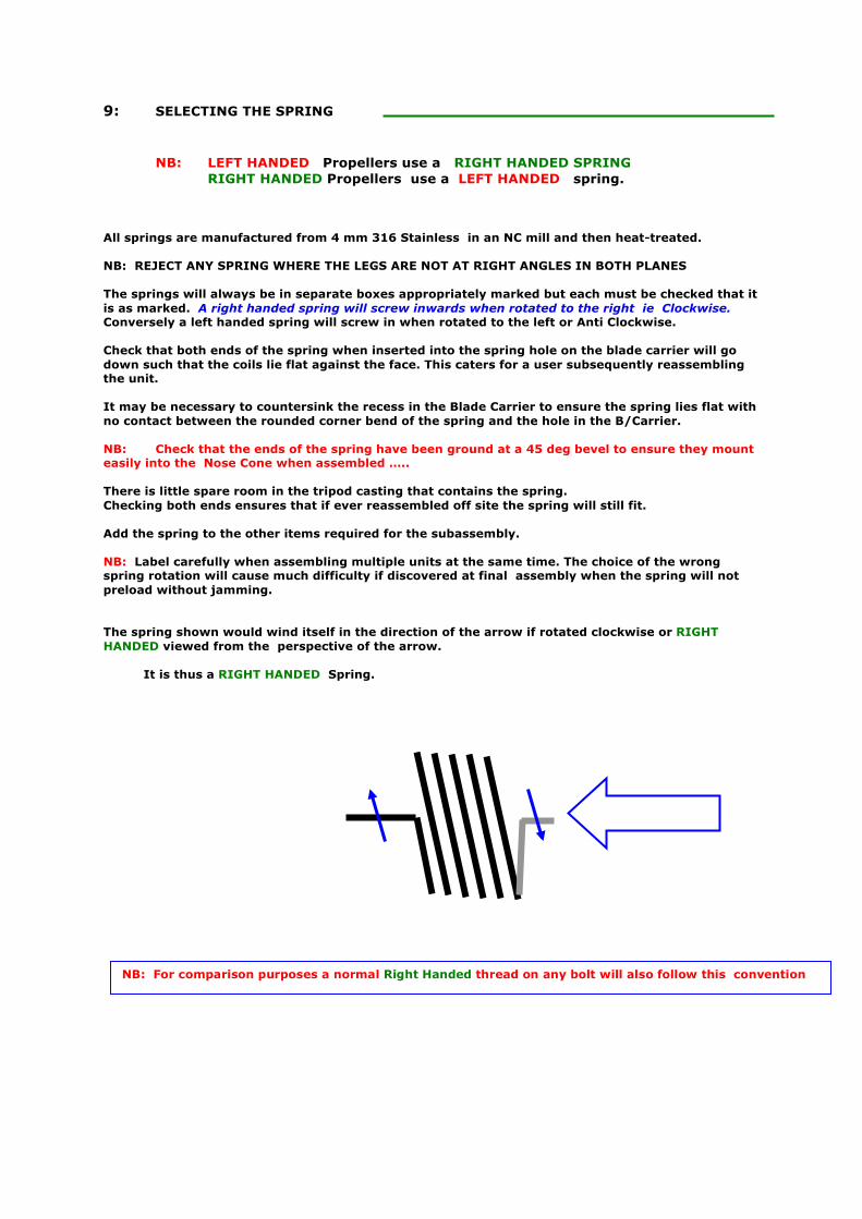
NB: LEFT HANDED Propellers use a RIGHT HANDED SPRING RIGHT HANDED Propellers use a LEFT HANDED spring.
All springs are manufactured from 4 mm 316 Stainless in an NC mill and then heat-treated. NB: REJECT ANY SPRING WHERE THE LEGS ARE NOT AT RIGHT ANGLES IN BOTH PLANES The springs will always be in separate boxes appropriately marked but each must be checked that it is as marked. A right handed spring will screw inwards when rotated to the right ie Clockwise. Conversely a left handed spring will screw in when rotated to the left or Anti Clockwise. Check that both ends of the spring when inserted into the spring hole on the blade carrier will go down such that the coils lie flat against the face. This caters for a user subsequently reassembling the unit. It may be necessary to countersink the recess in the Blade Carrier to ensure the spring lies flat with no contact between the rounded corner bend of the spring and the hole in the B/Carrier. NB: Check that the ends of the spring have been ground at a 45 deg bevel to ensure they mount easily into the Nose Cone when assembled ….. There is little spare room in the tripod casting that contains the spring. Checking both ends ensures that if ever reassembled off site the spring will still fit. Add the spring to the other items required for the subassembly. NB: Label carefully when assembling multiple units at the same time. The choice of the wrong spring rotation will cause much difficulty if discovered at final assembly when the spring will not preload without jamming. The spring shown would wind itself in the direction of the arrow if rotated clockwise or RIGHT HANDED viewed from the perspective of the arrow.
It is thus a RIGHT HANDED Spring.
NB: For comparison purposes a normal Right Handed thread on any bolt will also follow this convention
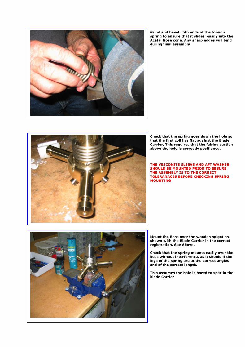
Grind and bevel both ends of the torsion spring to ensure that it slides easily into the Acetal Nose cone. Any sharp edges will bind during final assembly Check that the spring goes down the hole so that the first coil lies flat against the Blade Carrier, This requires that the fairing section above the hole is correctly positioned. THE VESCONITE SLEEVE AND AFT WASHER SHOULD BE MOUNTED PRIOR TO EBSURE THE ASSEMBLY IS TO THE CORRECT TOLERANACES BEFORE CHECKING SPRING MOUNTING Mount the Boss over the wooden spigot as shown with the Blade Carrier in the correct registration. See Above. Check that the spring mounts easily over the boss without interference, as it should if the legs of the spring are at the correct angles and of the correct length. This assumes the hole is bored to spec in the blade Carrier
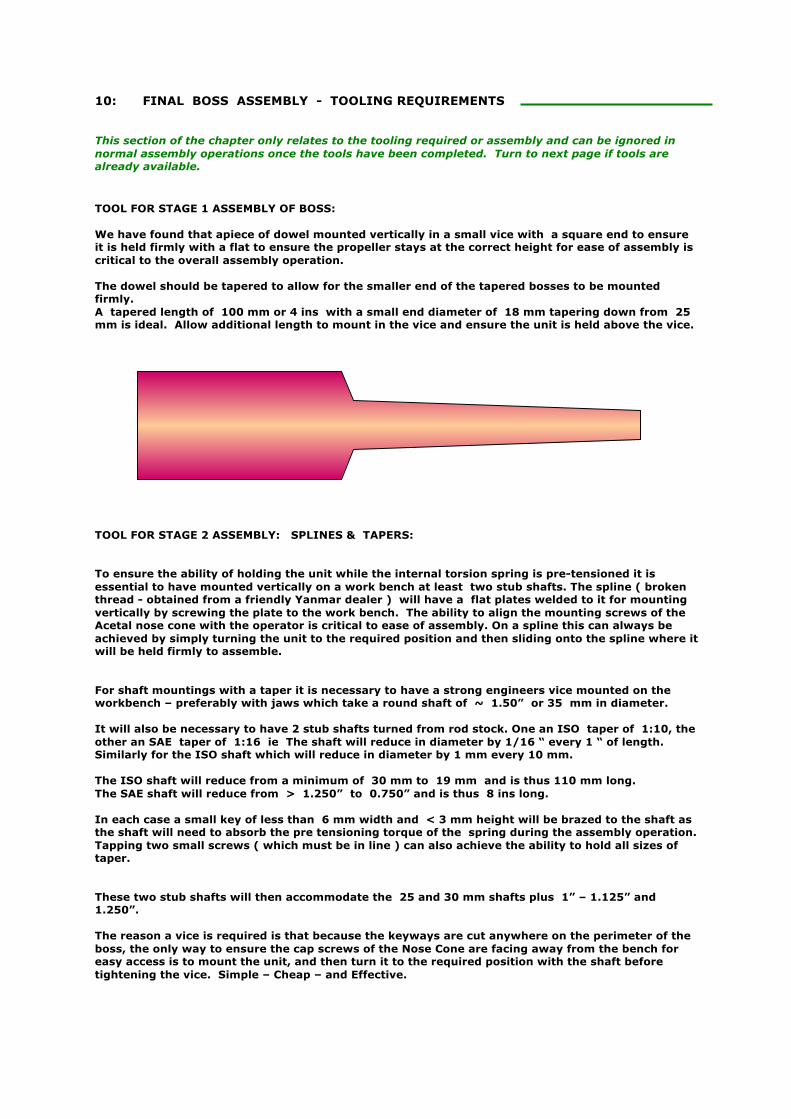
10: FINAL BOSS ASSEMBLY - TOOLING REQUIREMENTS This section of the chapter only relates to the tooling required or assembly and can be ignored in normal assembly operations once the tools have been completed. Turn to next page if tools are already available. TOOL FOR STAGE 1 ASSEMBLY OF BOSS: We have found that apiece of dowel mounted vertically in a small vice with a square end to ensure it is held firmly with a flat to ensure the propeller stays at the correct height for ease of assembly is critical to the overall assembly operation. The dowel should be tapered to allow for the smaller end of the tapered bosses to be mounted firmly. A tapered length of 100 mm or 4 ins with a small end diameter of 18 mm tapering down from 25 mm is ideal. Allow additional length to mount in the vice and ensure the unit is held above the vice. TOOL FOR STAGE 2 ASSEMBLY: SPLINES & TAPERS: To ensure the ability of holding the unit while the internal torsion spring is pre-tensioned it is essential to have mounted vertically on a work bench at least two stub shafts. The spline ( broken thread - obtained from a friendly Yanmar dealer ) will have a flat plates welded to it for mounting vertically by screwing the plate to the work bench. The ability to align the mounting screws of the Acetal nose cone with the operator is critical to ease of assembly. On a spline this can always be achieved by simply turning the unit to the required position and then sliding onto the spline where it will be held firmly to assemble. For shaft mountings with a taper it is necessary to have a strong engineers vice mounted on the workbench – preferably with jaws which take a round shaft of ~ 1.50” or 35 mm in diameter. It will also be necessary to have 2 stub shafts turned from rod stock. One an ISO taper of 1:10, the other an SAE taper of 1:16 ie The shaft will reduce in diameter by 1/16 “ every 1 “ of length. Similarly for the ISO shaft which will reduce in diameter by 1 mm every 10 mm. The ISO shaft will reduce from a minimum of 30 mm to 19 mm and is thus 110 mm long. The SAE shaft will reduce from > 1.250” to 0.750” and is thus 8 ins long. In each case a small key of less than 6 mm width and < 3 mm height will be brazed to the shaft as the shaft will need to absorb the pre tensioning torque of the spring during the assembly operation. Tapping two small screws ( which must be in line ) can also achieve the ability to hold all sizes of taper. These two stub shafts will then accommodate the 25 and 30 mm shafts plus 1” – 1.125” and 1.250”. The reason a vice is required is that because the keyways are cut anywhere on the perimeter of the boss, the only way to ensure the cap screws of the Nose Cone are facing away from the bench for easy access is to mount the unit, and then turn it to the required position with the shaft before tightening the vice. Simple – Cheap – and Effective.
11: FINAL BOSS ASSEMBLY First mount the tapered wooden spigot in one vice and the appropriate stub shaft in another so that the unit may be mounted firmly to preload the internal spring. This requires that the boss does not turn under the spring while the nose cone is being tightened up. Remove the nose cone and tripod so that you can hold the boss in one hand and allow the blade carrier to fall down two inches or 50 mm to expose the drive dogs. First check again the register with the two locking screw holes aligned with the blade carriers pins. With two internal dogs and three blades the drive dogs can only engage correctly in one position. The other position is incorrect. See the earlier pictures showing this registration Without turning the blade carrier relative to the boss – by using a knife insert ~ one teaspoon of Marine Grease into each side of the boss and the blade carriers sectors that receive the dogs. Smear the entire bearing mating surfaces on the Boss to ensure smooth rotation after assembly. NB: ENSURE THE ENTIRE BOSS BEARING SURFACE IS COVERED WITH GREASE DRY AREAS HAVE THE POTENTIAL TO BIND UNDER INITIAL OPERTION INSERT THE AFT WASHER WITH THE UPSTAND FACING FORWRAD INTO THE B/CARRIER Lower the boss into the blade carrier without rotation so registration is maintained. Pull the boss down fully and turn either way to ensure it is operating smoothly and any surplus grease is squeezed out which will then need to be wiped off with a clean rag. Mount this subassembly onto the wooden spigot over the nut recess with the nose of the unit up. Mount the tripod back onto the blade carrier remembering to put the internal mark over the spring hole in the blade carrier to ensure a known fitted position. Now using the knife again insert more of the grease into the groove between the tripod and the boss where the spring is to go. Attempt to keep the areas adjacent free of grease to ensure a clean surface. NB: Leave the area over the spring hole free so it can be subsequently located visually. Now insert the spring into the groove with one end of the spring going into the hole in the blade carrier. Press it home into the recess. Using a clean rag and Mineral Turps carefully clean all around the boss including the thrust groove which is going to take the spigot on the nose cone and which will contain the 3M 5200. Remove the 3M 5200 Fast Cure from the freezer where it is kept in a dry atmosphere to avoid curing between units prior to final assembly and allow it to come to room temperature. Ideally this should be removed from the freezer and allowed to climb to room temperature at least an hour before use. While rotating the boss on the spigot extrude a small bead at the upper or nose end of the thrust groove around the entire circumference. Place further beads around the area under the nose cone to ensure that under assembly it will all receive a thin film. Typically six vertical beads of ~ 2 mm will suffice Now smear a light coating of grease around the perimeter of the nose cone face that will move against the tripod. Check that the nose cone is clean in particular the thrust spigot on both halves. Clean with Mineral Turps if necessary and a clean rag. Using a small screw driver ease the spring spigot out so that the bottom half of the nose cone that contains the threaded section of the nose cone can be slipped over the spring and then pushed home so that it lies as it should around the boss and into the thrust groove completely. Now squeeze further 3M 5200 onto the two vertical faces of this bottom section of nose cone, sufficient to ensure it will fill the two gaps formed from the saw cut that split the nose cone into two. The finished space will be of the order of 1/8” or ~ 3 mm and just sufficient 3M 5200 should be used. Mount the other half of the nose cone onto the boss after checking again to ensure it is clean.
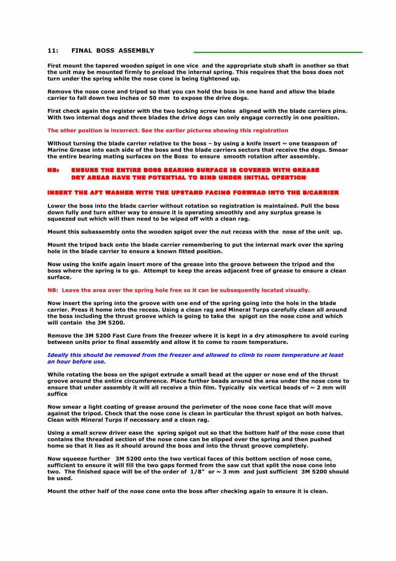
Mount the tripod into the grooves as shown for a Left Handed unit. A Right Handed unit will occupy the alternate grooves CHECK THE VESCONITE™ SLEEVE AND AFT WASHER HAVE BEEN FITTED FOR FINAL ASSEMBLY ENSURE GREASE IS SMEARED OVER ALL MOVING SURFACES FOR EASE OF ASSEMBLY Check that the spring bottoms correctly onto the base of the Blade Carrier REMEMBER: LEFT HANDED PROPS USE RIGHT HANDED SPRINGS AND VICA VERSA CHECK YOU HAVE THE CORRECT SPRING CHECK FULL AND FREE MOVEMENT After lowering the Blade Carrier by about 50 mm insert grease into the grooves swept by the dogs using a knife or spatula ENSURE THE ENTIRE BEARING SURFACE AS SHOWN IS SMEARED WITH GREASE FILL THE TWO RECESSES SWEPT BY THE DRIVE DOGS ON EITHER SIDE THIS WILL PREVENT ANY DRY AREAS CAUSING BINDING IN INITIAL OPERATION BEFORE THE GREASE CAN WORK IT’S WAY DOWN THE ENTIRE BEARING SURFACE GREASE THE AREA UNDER THE SLEEVE AND AFT WASHER
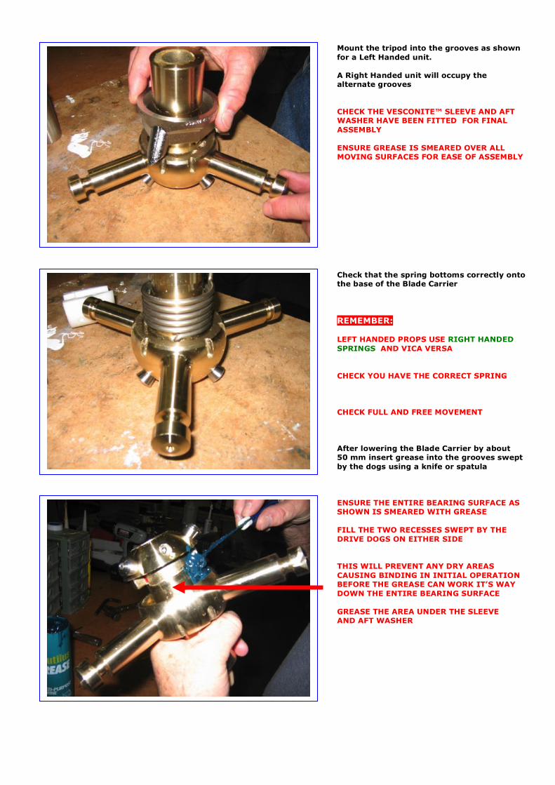
BEFORE FINAL ASSEMBLY – CHECK AGAIN THE CONTACT SURFACES HAVE NO BURRS TO ENSURE SMOOTH MOVEMENT POST ASSEMBLY Ensure the boss is aligned as previously shown with the Blade Carrier when in the driving position Rotate the Boss in the driving direction viewed from astern facing forward THIS IS CRITICAL THE LOCKING SCREWS MUST ALIGN WITH THE LEGS AT THE ENDS OF EACH MOTION AS SHOWN Mount the boss over a wooden spigot to enable ease of assembly At this stage rotate the boss with a knife holding grease to ensure a liberal amount of grease over the area where the spring will go MOUNT THE TRIPOD MAKING SURE THE ROTATION IS CONFIRMED IN THE CORRECT POSITION WIPE THE BOSS CLEAN BEFORE INSERTING SPRING INSERT 2 x 0.004” CLEARANCE FEELER GAUGES TO ENSURE CORRECT CLEARANCE POST ASSEMBLY UNDER TRIPOD THIS ENSUES THE THRUST SURFACES ARE CORRECTLY ALIGNED INTERNALLY PRIOR TO TIGHTENING WHEN THEY ARE REMOVED AGAIN

After ensuring the boss surface is clean – hold the spring tail out with a screw driver and mount the lower half of the Nose Cone onto the boss NB: Ensure no swarf is loose as it will fall onto the grease and cause subsequent binding of the Nose Cone on the Tripod casting during the reversing function operation. ENSURE A SMEAR OF GREASE IS ON THE TRIPOD SURFACE THAT WILL CONTACT THE NOSE SURFACE TO ASSIST ASSEMBLY AND SMOOTH OPERATION
NB: EARLY UNITS WITH AT LEAST ONE AB2 COMPONENT DID NOT REQUIRE INTERNAL SLEEVES OR AFT WASHERS. AB2 DOES NOT BIND ON ITSELF UNLIKE SS316 WHICH IS PRONE TO WHAT IS DESCRIBED AS “ GALLING “ IN THE LITERATURE UNITS ASSEMBLED WITH ONLY SS 316 COMPONENTS WILL HAVE BOTH THE AFT WASHER AND INTERNAL SLEEVE IN VESCONITE™
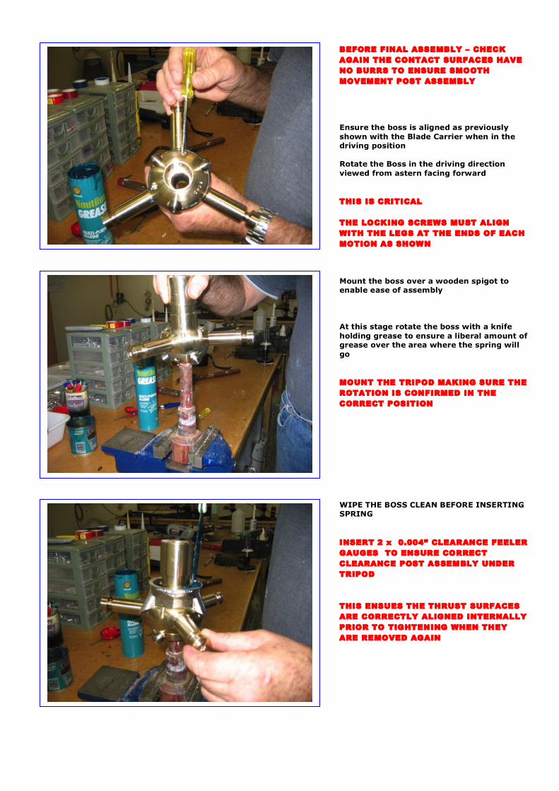
Place a small portion of 3M 5200 on the ends of each of the 4 Socket Head screws This will ensure they are locked into the Nose when dried ENSURE THE FEELER GUAGES ARE IN Wind in the Cap Screws with a slow variable speed battery drill. Do not over tighten at this stage as the nose cone has to still rotate and hold the spring tension while it is finally assembled. The knurled finish will make rotation of the Nose Cone quite difficult once more than a small amount of tension is applied to the Cap Screws. The objective is to ensure only sufficient tightening of the cap screws to ensure the Nose Cone will not rotate with the pre load spring tension that is going to be applied Transfer the unit to the appropriate too or spline vice mount so it can be rotated to access the Cap Screws easily AT NO STAGE USE A HAMMER OR ASYMETRIC FORCE ON THE LEGS AS THIS HAS THE POTENTIAL TO SCORE THE BEARING SURFACE AND CAUSE SUBSEQENT SEIZING DURING NORMAL OPERATIONS Mount the tool into the heads of the Cap Screws so the internal spring can be pre-tensioned It is easier at this stage to turn the mounting shaft in the vice to bring the heads of the Cap Screws so as to face the operator for ease of tightening and control CHECK THE SPRING TENSION SCHEMATIC BELOW TO GIVE THE DIRECTION OF SPRING TENSION LOADING BY TYPE THIS ALSO DEPENDS UPON THE DIRECTION THE UNIT IS MOUNTED THE DIRECTION IS MARKED BY THE TOOL
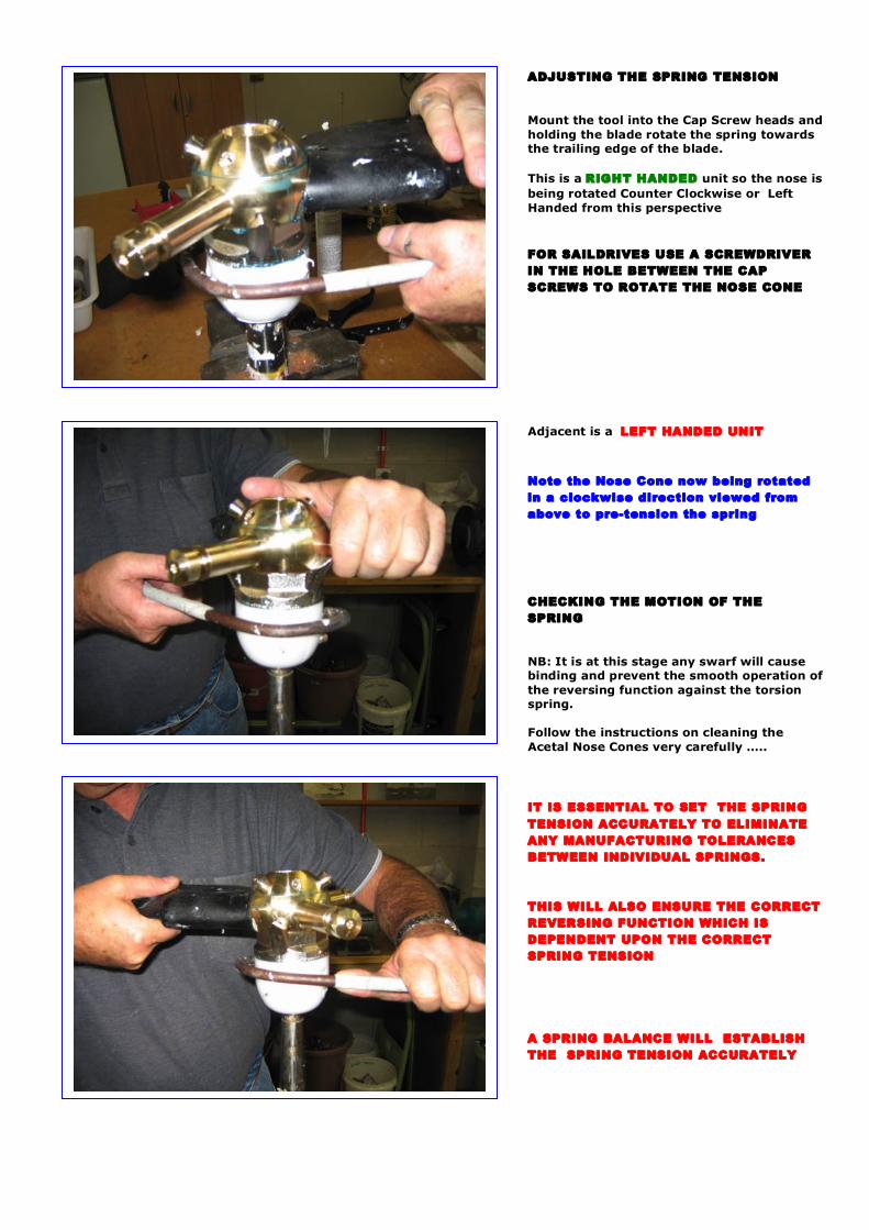
ADJUSTING THE SPRING TENSION Mount the tool into the Cap Screw heads and holding the blade rotate the spring towards the trailing edge of the blade. This is a RIGHT HANDED unit so the nose is being rotated Counter Clockwise or Left Handed from this perspective FOR SAILDRIVES USE A SCREWDRIVER IN THE HOLE BETWEEN THE CAP SCREWS TO ROTATE THE NOSE CONE Adjacent is a LEFT HANDED UNIT Note the Nose Cone now being rotated in a clockwise direction viewed from above to pre-tension the spring CHECKING THE MOTION OF THE SPRING NB: It is at this stage any swarf will cause binding and prevent the smooth operation of the reversing function against the torsion spring. Follow the instructions on cleaning the Acetal Nose Cones very carefully ….. IT IS ESSENTIAL TO SET THE SPRING TENSION ACCURATELY TO ELIMINATE ANY MANUFACTURING TOLERANCES BETWEEN INDIVIDUAL SPRINGS. THIS WILL ALSO ENSURE THE CORRECT REVERSING FUNCTION WHICH IS DEPENDENT UPON THE CORRECT SPRING TENSION A SPRING BALANCE WILL ESTABLISH THE SPRING TENSION ACCURATELY
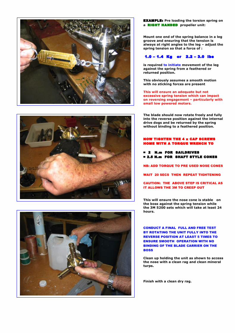
EXAMPLE: Pre loading the torsion spring on a RIGHT HANDED propeller unit: Mount one end of the spring balance in a leg groove and ensuring that the tension is always at right angles to the leg – adjust the spring tension so that a force of : 1.0 – 1.4 Kg or 2.2 – 3.0 lbs is required to initiate movement of the leg against the spring from a feathered or returned position. This obviously assumes a smooth motion with no sticking forces are present This will ensure an adequate but not excessive spring tension which can impact on reversing engagement – particularly with small low powered motors. The blade should now rotate freely and fully into the reverse position against the internal drive dogs and be returned by the spring without binding to a feathered position. NOW TIGHTEN THE 4 x CAP SCREWS HOME WITH A TORQUE WRENCH TO = 2 N.m FOR SAILDRIVES = 2.5 N.m FOR SHAFT STYLE CONES NB: ADD TORQUE TO PRE USED NOSE CONES WAIT 20 SECS THEN REPEAT TIGHTENING CAUTION: THE ABOVE STEP IS CRITICAL AS IT ALLOWS THE 3M TO CREEP OUT This will ensure the nose cone is stable on the boss against the spring tension while the 3M 5200 sets which will take at least 24 hours. CONDUCT A FINAL FULL AND FREE TEST BY ROTATING THE UNIT FULLY INTO THE REVERSE POSITION AT LEAST 5 TIMES TO ENSURE SMOOTH OPERATION WITH NO BINDING OF THE BLADE CARRIER ON THE BOSS Clean up holding the unit as shown to access the nose with a clean rag and clean mineral turps. Finish with a clean dry rag.
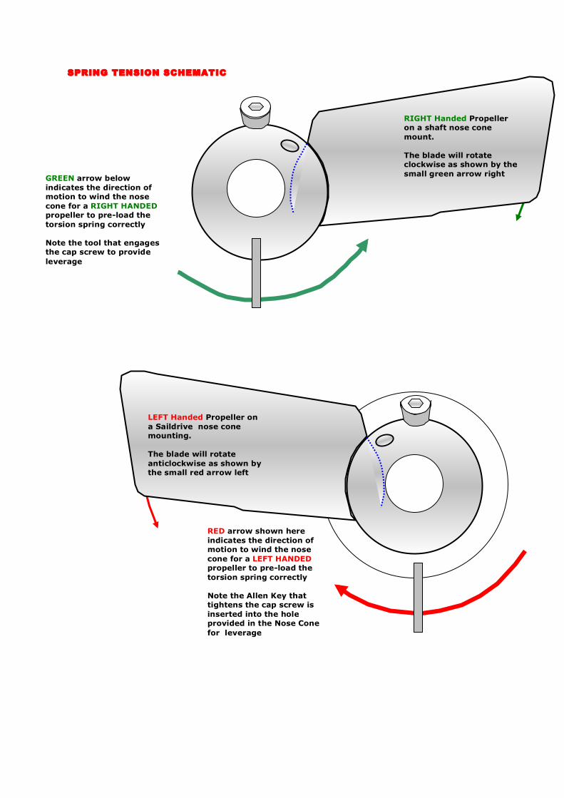
SPRING TENSION SCHEMATIC
RIGHT Handed Propeller on a shaft nose cone mount. The blade will rotate clockwise as shown by the small green arrow right GREEN arrow below
indicates the direction of motion to wind the nose cone for a RIGHT HANDED propeller to pre-load the torsion spring correctly Note the tool that engages the cap screw to provide leverage
LEFT Handed Propeller on a Saildrive nose cone mounting. The blade will rotate anticlockwise as shown by the small red arrow left
RED arrow shown here indicates the direction of motion to wind the nose cone for a LEFT HANDED propeller to pre-load the torsion spring correctly Note the Allen Key that tightens the cap screw is inserted into the hole provided in the Nose Cone for leverage
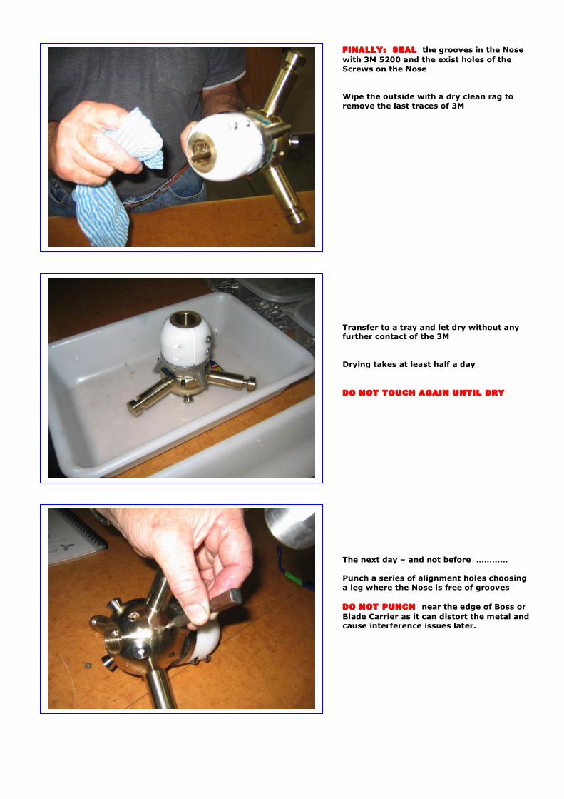
FINALLY: SEAL the grooves in the Nose with 3M 5200 and the exist holes of the Screws on the Nose Wipe the outside with a dry clean rag to remove the last traces of 3M Transfer to a tray and let dry without any further contact of the 3M Drying takes at least half a day DO NOT TOUCH AGAIN UNTIL DRY The next day – and not before ………… Punch a series of alignment holes choosing a leg where the Nose is free of grooves DO NOT PUNCH near the edge of Boss or Blade Carrier as it can distort the metal and cause interference issues later.

Alignment marks high lighted with pen. These are used to assist re-assembly for a user at a later date if ever required as they eliminate any spring pre tensioning issues. Check the nut diameter and length are to spec. or are machined to spec. CHECK AGAINST THE ORDER FOR THREAD REMEMBER THAT NEW YANMAR SD40 and SD50 SAILDRIVES REQUIRE A M20 x 2 NUT CAUTION: SD31’s CAN USE EITHER …. SAE 1 1/8” Bosses require 1/8” or 0.125” be removed from the threaded end of a standard ¾” UNC Nut as used on an SAE 1” shaft. Chamfer the end and clean up. This reduces inventory for the limited volumes required of this size. Seal the 3M by wrapping with masking tape and then placing into the freezer. Remember to remove it prior to use next time and allow to thaw to ensure it flows freely.
12: SUMMARY OF ASSEMBLY OPERATIONS The following notes provide an overview of assembly of a unit and may be used in conjunction with the previous chapters for specific cross reference where there is any elaboration required for a particular assembly operation. FUNCTION OVERVIEW … 1: Select a boss using the Boss Selection Chart to match the particular orders to be assembled – Remove 5200 from freezer 2: Assemble the Boss with a Blade Carrier – Check for interference Clean and de-burr Blade Carrier 3: De-Burr Flats & Internal Tap burrs
Wash with soap and water with Teepol Install the 2 x M8 locking screws Install the 3 x Reversing Rollers with Loctite – Check free
4: Fit the Tripod to the Blade Carrier CHECK CONTACT SURFACES FOR BURRS – HONE & FILE 5: Select the Nose Cone – Shaft or Saildrive ( Lombardini option ) Split on cut-off saw Drill spring hole in jig Remove internal corners on Nose Cone Sand faces on Sanding Disc - De-burr all edges and clean internal spigot 6: Machine the Tripod to tolerances for final assembly INSERT FEELER GAUGES UNDER TRIPOD FOR CLEARANCE TOLERANCES 7: Select the Spring – Chamfer ends and check depth 8: Assemble the Boss with grease with 3M 5200 on the Locking Screws only Preload the internal Torsion Spring Seal the Nose Cone joins with 3M 5200 and exit holes of the screws Torque Nose Cone screws down Clean up unit with Mineral Turps – Leave to dry


![MARINE DIESEL ENGINES Yanmar Saildrive SD50 · PDF fileYanmar Saildrive SD50 Series MARINE DIESEL ENGINES Yanmar Saildrive SD60 Series ... [propeller shaft - fwd] viewed from flywheel](https://img.pdfslide.us/doc/110x75/5a75dbdf7f8b9aea3e8cd565/marine-diesel-engines-yanmar-saildrive-sd50-yanmar-saildrive-sd50-series.jpg)


![MARINE DIESEL ENGINES Yanmar Saildrive SD20 Yanmar ...€¦ · Yanmar Saildrive Type SD25 Reduction gear system Constant mesh gear with dog clutch Reduction ratio [fwd/asn] 2.64/2.64](https://img.pdfslide.us/doc/110x75/6079f2b58c534c4ae36adf4c/marine-diesel-engines-yanmar-saildrive-sd20-yanmar-yanmar-saildrive-type-sd25.jpg)