Embed Size (px)
Citation preview

ONE BUTTON BANDIT KIT
MODEL K-34
Assembly and Instruction Manual
Elenco™ Electronics, Inc.Copyright © 1989 Elenco™ Electronics, Inc. Revised 2002 REV-D 753234
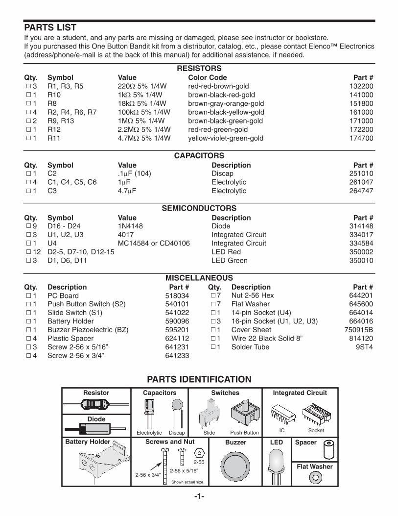
PARTS LISTIf you are a student, and any parts are missing or damaged, please see instructor or bookstore.If you purchased this One Button Bandit kit from a distributor, catalog, etc., please contact Elenco™ Electronics(address/phone/e-mail is at the back of this manual) for additional assistance, if needed.
RESISTORSQty. Symbol Value Color Code Part #
3 R1, R3, R5 220Ω 5% 1/4W red-red-brown-gold 1322001 R10 1kΩ 5% 1/4W brown-black-red-gold 1410001 R8 18kΩ 5% 1/4W brown-gray-orange-gold 1518004 R2, R4, R6, R7 100kΩ 5% 1/4W brown-black-yellow-gold 1610002 R9, R13 1MΩ 5% 1/4W brown-black-green-gold 1710001 R12 2.2MΩ 5% 1/4W red-red-green-gold 1722001 R11 4.7MΩ 5% 1/4W yellow-violet-green-gold 174700
CAPACITORSQty. Symbol Value Description Part #
1 C2 .1µF (104) Discap 2510104 C1, C4, C5, C6 1µF Electrolytic 2610471 C3 4.7µF Electrolytic 264747
SEMICONDUCTORSQty. Symbol Value Description Part #
9 D16 - D24 1N4148 Diode 3141483 U1, U2, U3 4017 Integrated Circuit 3340171 U4 MC14584 or CD40106 Integrated Circuit 33458412 D2-5, D7-10, D12-15 LED Red 3500023 D1, D6, D11 LED Green 350010
MISCELLANEOUS
-1-
Resistor Capacitors
PARTS IDENTIFICATION
Electrolytic
Switches
Diode
Buzzer
Qty. Description Part #1 PC Board 5180341 Push Button Switch (S2) 5401011 Slide Switch (S1) 5410221 Battery Holder 5900961 Buzzer Piezoelectric (BZ) 5952014 Plastic Spacer 6241123 Screw 2-56 x 5/16” 6412314 Screw 2-56 x 3/4” 641233
Qty. Description Part #7 Nut 2-56 Hex 6442017 Flat Washer 6456001 14-pin Socket (U4) 6640143 16-pin Socket (U1, U2, U3) 6640161 Cover Sheet 750915B1 Wire 22 Black Solid 8” 8141201 Solder Tube 9ST4
Discap Slide Push Button
Integrated Circuit
IC Socket
LEDScrews and Nut
2-56 x 3/4”2-56 x 5/16”
2-56
Shown actual size.
Spacer
Flat Washer
Battery Holder

The One Button Bandit is better known in Las Vegasas the One Arm Bandit. Our device has no arms,but instead a button. Therefore, we call it the OneButton Bandit.
The One Button Bandit is a simplified version of anelectronic slot machine. It contains three columns of
five light emitting diodes (LED). When the switch S2is pressed, the LEDs will flash on and offaccompanied by sound. When the bandit stops,only one LED in each column will remain lit. If threegreen LEDs light up, you win the jackpotaccompanied by sound.
-2-
IDENTIFYING CAPACITOR VALUESCapacitors will be identified by their capacitance value in pF (picofarads), nF (nanofarads), or µF (microfarads).Most capacitors will have their actual value printed on them. Some capacitors may have their value printed inthe following manner.
Second Digit
First Digit
Multiplier
Tolerance
The above value is 10 x 1,000 = 10,000pF or .01µF The letter K indicates a tolerance of +10% The letter J indicates a tolerance of +5%
For the No. 0 1 2 3 4 5 8 9
Multiply By 1 10 100 1k 10k 100k .01 0.1Multiplier
Note: The letter “R” may be used at times tosignify a decimal point; as in 3R3 = 3.310µF 16V
IDENTIFYING RESISTOR VALUESUse the following information as a guide in properly identifying the value of resistors.
BAND 11st Digit
Color DigitBlack 0Brown 1Red 2Orange 3Yellow 4Green 5Blue 6Violet 7Gray 8White 9
BAND 22nd Digit
Color DigitBlack 0Brown 1Red 2Orange 3Yellow 4Green 5Blue 6Violet 7Gray 8White 9
Multiplier
Color MultiplierBlack 1Brown 10Red 100Orange 1,000Yellow 10,000Green 100,000Blue 1,000,000Silver 0.01Gold 0.1
ResistanceTolerance
Color ToleranceSilver +10%Gold +5%Brown +1%Red +2%Orange +3%Green +.5%Blue +.25%Violet +.1%
Bands
1 2 Multiplier
Tolerance
103K100
INTRODUCTION
THEORY OF OPERATIONFigure 1 shows the block diagram of the One ButtonBandit. This block diagram consists of threeidentical circuits: (the basic has a timer, a decadecounter, and five LEDs), the Clock Oscillator, theSound Circuit and the Key of Ring.
Timer
Counter
Timer
Counter
Timer
Counter
LEDsClock
KeyRing
SoundCircuit
LEDs
LEDs
1
2
3
Figure 1

-3-
THE CLOCK OSCILLATORThe clock oscillator is an electronic circuit that putsout a series of high and low voltages. It is a squarewave oscillator whose frequency is controlled by thevalue of resistor and capacitor (see Figure 2a). Theclock oscillator consists of Part A of the MC14584integrated circuit. Figure 2b shows a diagram of theMC14584.
The MC14584 is a hex schmit trigger. The values ofR7 and C1 chosen give a frequency of about 30cycles per second. When the switch S1 is turnedON, the clock circuit oscillates pulses. The pulseswill be before switch S1 is in the “ON” position. Theygo to the clock input of decade counters U1, U2 andU3 pin 14.
THE DECADE COUNTERThe 4017 IC is a 5 stage divide by 10 counter.Figure 3 shows a diagram of this IC.
This IC has 10 outputs and a clear input. Only oneof the 10 outputs will be high at any given time. Theother 9 will be low. Let’s assume that output 1 ishigh. If a pulse is fed into the clock input, output 1will go low and output 2 will go high. Each clock
pulse will move the output one position. Connect anLED to the output, it will light only when the outputgoes high. It is obvious that when the clock isrunning, the LEDs will flash on and off with thespeed of the clock. When the clock stops, only oneLED will be lit.
In this design, 5 LEDs are used per IC, but thecounter has 10 outputs. If the clock stops at anoutput without an LED, nothing will light. To preventthis, the 4017 IC is reset after hitting the 5th output.This is simply done by tying the 6th output to theclear pin (pin 1 and pin 15 shorted together). Whenthe clock triggers output 5 on, the next pulse goesback to output 1.
THE TIMERThe One Button Bandit has three timers. The timersstart when you turn ON the push button switch. Thetimers consist of Part D of the MC14584, R13 andC6; Part E and R12, C5; Part F and R11, C4. Thevalues of the resistors and capacitors give the timesof work for each decade counter.
THE LIGHT EMITTING DIODES (LED)The operation of the LED is very simple. Whencurrent flows through the LED, it will emit light. Notethat the LED is connected between an IC output andground through a resistor. When the IC output goeshigh, the LED will light. The resistor limits the currentso that the LED will not be damaged.
THE SOUND CIRCUITThis circuit consists of the buzzer’s oscillator and thepiezoelectric buzzer. The oscillator consists of PartB of the MC14584 integrated circuit. The value ofresistor R8 and capacitor C2 chosen given afrequency of about 3000 cycles per second. Thisoscillator oscillates pulses only when the decadecounters work. The pulses from this oscillator go tothe buzzer. It is accompanied by sound when thebandit works.
THE KEY OF RINGWhen the One Button Bandit stops and the threegreen LEDs light, you will get the ring signal. Thissound signal will be before you push the switch S2again. The Key of Ring is an oscillator and consistsof Part C of the MC14584. The values of resistor R9and capacitor C3 give the frequency of ring sound.
Figure 3
32471015691112
VCC - Pin 16GND - Pin 8
15
14
1
Q0Q1Q2Q3Q4Q5Q6Q7Q8Q9
COUT
Clock
ClockEnable
Reset
A1 2
B3 4
C5 6
D9 8
E11 10
F13 12
Figure 2b
R
C
Figure 2a

-4-
IntroductionThe most important factor in assembling your K-34 One Arm Bandit Kit is good soldering techniques. Using theproper soldering iron is of prime importance. A small pencil type soldering iron of 25 - 40 watts isrecommended. The tip of the iron must be kept clean at all times and well tinned.
Safety Procedures• Wear eye protection when soldering.• Locate soldering iron in an area where you do not have to go around it or reach over it.• Do not hold solder in your mouth. Solder contains lead and is a toxic substance. Wash your hands
thoroughly after handling solder.• Be sure that there is adequate ventilation present.
Assemble ComponentsIn all of the following assembly steps, the components must be installed on the top side of the PC board unlessotherwise indicated. The top legend shows where each component goes. The leads pass through thecorresponding holes in the board and are soldered on the foil side.Use only rosin core solder of 63/37 alloy.
DO NOT USE ACID CORE SOLDER!
CONSTRUCTION
Solder Soldering Iron
Foil
Solder
Soldering Iron
Foil
Component Lead
Soldering Iron
Circuit Board
Foil
Rosin
Soldering iron positionedincorrectly.
Solder
GapComponent Lead
Solder
Soldering Iron
DragFoil
1. Solder all components fromthe copper foil side only.Push the soldering iron tipagainst both the lead andthe circuit board foil.
2. Apply a small amount ofsolder to the iron tip. Thisallows the heat to leave theiron and onto the foil.Immediately apply solder tothe opposite side of theconnection, away from theiron. Allow the heatedcomponent and the circuitfoil to melt the solder.
1. Insufficient heat - thesolder will not flow onto thelead as shown.
3. Allow the solder to flowaround the connection.Then, remove the solderand the iron and let theconnection cool. Thesolder should have flowedsmoothly and not lumparound the wire lead.
4. Here is what a good solderconnection looks like.
2. Insufficient solder - let thesolder flow over theconnection until it iscovered. Use just enoughsolder to cover theconnection.
3. Excessive solder - couldmake connections that youdid not intend to betweenadjacent foil areas orterminals.
4. Solder bridges - occurwhen solder runs betweencircuit paths and creates ashort circuit. This is usuallycaused by using too muchsolder. To correct this,simply drag your solderingiron across the solderbridge as shown.
What Good Soldering Looks LikeA good solder connection should be bright, shiny,smooth, and uniformly flowed over all surfaces.
Types of Poor Soldering Connections

ASSEMBLE COMPONENTS TO THE PC BOARD
-5-
Figure AElectrolytic capacitors have polarity. Be sureto mount them with the negative (–) lead(marked on side) in the correct hole. Mountthe electrolytics horizontal to the PC board.Bend the leads at right angles and theninsert the leads into the PC board.
C5 - 1µF Electrolytic Cap.(see Figure A)
U3 - 16-pin IC SocketU3 - 4017 Integrated Circuit
(see Figure B)
J4 - Jumper Wire(see Figure C)
R11 - 4.7MΩ 5% 1/4W Resistor(yellow-violet-green-gold)
C4 - 1µF Electrolytic Cap.(see Figure A)
R5 - 220Ω 5% 1/4W Resistor(red-red-brown-gold)
J3 - Jumper Wire(see Figure C)
J2 - Jumper Wire(see Figure C)
R6 - 100kΩ 5% 1/4W Resistor(brown-black-yellow-gold)
C1 - 1µF Electrolytic Cap.(see Figure A)
U2 - 16-pin IC SocketU2 - 4017 Integrated Circuit
(see Figure B)
R3 - 220Ω 5% 1/4W Resistor(red-red-brown-gold)
R4 - 100kΩ 5% 1/4W Resistor(brown-black-yellow-gold)
D19 - 1N4148 DiodeD18 - 1N4148 DiodeD16 - 1N4148 Diode
(see Figure D)
R2 - 100kΩ 5% 1/4W Resistor(brown-black-yellow-gold)
U1 - 16-pin IC SocketU1 - 4017 Integrated Circuit
(see Figure B)
R1 - 220Ω 5% 1/4W Resistor(red-red-brown-gold)
D22 - 1N4148 Diode(see Figure D)
S2 - Push Button Switch
R12 - 2.2MΩ 5% 1/4W Resistor(red-red-green-gold)
D23 - 1N4148 Diode(see Figure D)
R13 - 1MΩ 5% 1/4W Resistor(brown-black-green-gold)
D24 - 1N4148 Diode(see Figure D)
C6 - 1µF Electrolytic Cap.(see Figure A)
U4 - 14-pin IC SocketU4 - MC14584 or CD40106 IC
(see Figure B)
R7 - 100kΩ 5% 1/4W Resistor(brown-black-yellow-gold)
D17 - 1N4148 Diode(see Figure D)
R10 - 1kΩ 5% 1/4W Resistor(brown-black-red-gold)
D21 - 1N4148 Diode(see Figure D)
R9 - 1MΩ 5% 1/4W Resistor(brown-black-green-gold)
D20 - 1N4148 Diode(see Figure D)
R8 - 18kΩ 5% 1/4W Resistor(brown-gray-orange-gold)
C2 - .1µF Discap (104)
C3 - 4.7µF Electrolytic Cap.(see Figure A)
S1 - Slide Switch
J1 - Jumper Wire(see Figure C)
Figure BInsert the IC socket into the PC board withthe notch in the direction shown on the toplegend. Solder the IC socket into place.Insert the IC into the socket with the notchin the same direction as the notch on thesocket.
Polarity Marking
Notch
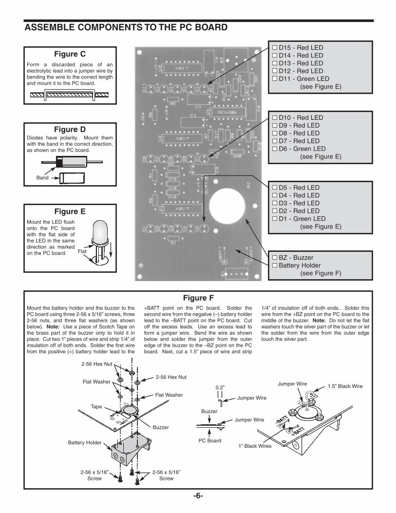
Mount the battery holder and the buzzer to thePC board using three 2-56 x 5/16” screws, three2-56 nuts, and three flat washers (as shownbelow). Note: Use a piece of Scotch Tape onthe brass part of the buzzer only to hold it inplace. Cut two 1” pieces of wire and strip 1/4” ofinsulation off of both ends. Solder the first wirefrom the positive (+) battery holder lead to the
+BATT point on the PC board. Solder thesecond wire from the negative (–) battery holderlead to the –BATT point on the PC board. Cutoff the excess leads. Use an excess lead toform a jumper wire. Bend the wire as shownbelow and solder this jumper from the outeredge of the buzzer to the –BZ point on the PCboard. Next, cut a 1.5” piece of wire and strip
1/4” of insulation off of both ends.. Solder thiswire from the +BZ point on the PC board to themiddle of the buzzer. Note: Do not let the flatwashers touch the silver part of the buzzer or letthe solder from the wire from the outer edgetouch the silver part.
Figure F
Figure EMount the LED flushonto the PC boardwith the flat side ofthe LED in the samedirection as markedon the PC board.
ASSEMBLE COMPONENTS TO THE PC BOARD
D15 - Red LEDD14 - Red LEDD13 - Red LEDD12 - Red LEDD11 - Green LED
(see Figure E)
D10 - Red LEDD9 - Red LEDD8 - Red LEDD7 - Red LEDD6 - Green LED
(see Figure E)
D5 - Red LEDD4 - Red LEDD3 - Red LEDD2 - Red LEDD1 - Green LED
(see Figure E)
BZ - BuzzerBattery Holder
(see Figure F)
Figure CForm a discarded piece of anelectrolytic lead into a jumper wire bybending the wire to the correct lengthand mount it to the PC board.
Figure DDiodes have polarity. Mount themwith the band in the correct direction,as shown on the PC board.
-6-
Band
Flat
2-56 Hex Nut
2-56 Hex Nut
Flat Washer
Flat Washer
2-56 x 5/16”Screw
2-56 x 5/16”Screw
Battery Holder
Buzzer
0.2”
Jumper Wire
Buzzer
Jumper Wire
PC Board
Jumper Wire
Tape
1” Black Wires
1.5” Black Wire

Put the 9V alkaline battery into the battery holder.Slide the switch to the ON (top) position and pushon the button switch. The LEDs will flash ON andOFF accompanied by sound. If it is OK, go to theFinal Assembly.
TROUBLESHOOTING
1. One of the most frequently occurring problems ispoor solder connections.
a) Tug slightly on all parts to make sure thatthey are indeed soldered.
b) All solder connections should be shiny.Resolder any that are not.
c) Solder should flow into a smooth puddlerather than a round ball. Resolder anyconnection that has formed into a ball.
d) Have any solder bridges formed? A solderbridge may occur if you accidentally touchan adjacent foil by using too much solder orby dragging the soldering iron acrossadjacent foils. Break the bridge with yoursoldering iron.
2. Be sure that all components have been mountedin their correct places.
a) Be sure that diodes D16 - D24 have notbeen installed backwards. The band on thediodes should be in the same direction asmarked on the PC board.
b) Are electrolytics C1, C3 - C6 installedcorrectly? These capacitors have polarity.Be sure that the negative lead is in thecorrect pad.
c) Be sure that the ICs are installed correctly.The notch should be in the same directionas shown on the top legend of the PC board.
d) Be sure that the LED has been installedcorrectly. The flat side of the LED should bein the same direction as marked on the toplegend of the PC board.
-7-
FINAL ASSEMBLY1. Using a small knife or scissors, very carefully cut out the holes on the cover sheet as shown in Figure G.
ON
ONE BUTTON BANDITONE BUTTON BANDIT
Electronic Slot MachineElectronic Slot Machine
Wager Back for Any 2 Green Lights
Copyright © 1998 Elenco Electronics, Inc.
50-1
25-1
15-1
10-1
5-1
Cut
Out
Cut
Out
Cut
Out
Cut Out Cut Out
Figure G
PUSH3/16” x 5/16” 5/16” x 5/16”
3/32” Diameter
Contact Elenco™ Electronics if you have any problems. DO NOT contact your place of purchase as they willnot be able to help you.

-8-
2. Next, cut out the holes on the clam shell asshown in Figure H. To do this, you’re going tohave to position the cover sheet inside theclamshell to where you want it mounted. Tape
the sheet to the clam shell as shown. Now cutout the four corner holes, the ON/OFF Switchhole, and the Push Button Switch hole. Removethe tape.
Figure H
ON
ONE BUTTON BANDITONE BUTTON BANDIT
Copyright © 1998 Elenco Electronics, Inc.
50-1
25-1
15-1
10-1
5-1
PUSH
Cut Out
Cut Out Cut Out
Tape
Tape
Electronic Slot MachineElectronic Slot Machine
Wager Back for Any 2 Green Lights
2-56 x 3/4” Screws
2-56 x 3/4” Screws
Flat Washers
Flat Washers
3. Insert the four 2-56 x 3/4” screws and fourwashers into the holes of the clamshell andcover sheet as shown in Figure I. Next, slide onthe four plastic spacers onto the 2-56 x 3/4”
screws as shown in Figure J. Now slide the PCboard onto the screws as shown. Finally, lockeverything into place by threading on the four 2-56hex nuts onto the screws as shown in Figure J.
Figure I

-9-
FINAL ASSEMBLY (CONTINUED)
Plastic Spacers
Plastic Spacers
2-56 Nuts
2-56 Nuts
PC Board
Figure J
1. In electronics, a capacitor is a . . .a) counter. c) light emitting diode.b) generator.d) storage device.
2. LED means . . .a) light emitting device. c) long electronic delay.b) light emitting diode. d) light electric diode.
3. The clock oscillator generates a . . .a) sound pulses. c) periodic waveform.b) DC voltage. d) light pulses.
4. The decade counter is triggered by . . .a) the timer. c) LEDs.b) the sound circuit. d) the clock oscillator.
5. The key of ring gives the sound ring signal when . . .
a) the three green LEDs light.b) any three LEDs light.c) three LEDs light up in a row.
6. The buzzer transforms . . .a) electrical signals to light.b) electrical signals to sound.c) light to electrical signals.
7. The probability of winning any green LED is . . .a) 4% c) 60%b) 25% d) 0.8%
8. The probability of winning three green LEDs is . . .a) 4% c) 20%b) 25% d) 0.8%
Answers:1.D;2.B;3.C;4.D;5.A;6.B;7.C;8.D
QUIZ
Cover Sheet

SCHEMATIC DIAGRAM
-10-

Elenco Electronics, Inc.150 W. Carpenter Avenue
Wheeling, IL 60090(847) 541-3800
http://www.elenco.come-mail: [email protected]