Embed Size (px)
Citation preview
J.Tiberghien - VUB09-07- K.Steenhaut & J.Tiberghien - VUB1
TelecommunicationsConcepts
Chapter 1.5
Communications
Media
J.Tiberghien - VUB09-07- K.Steenhaut & J.Tiberghien - VUB2
Contents
• Optical fibers
• Coaxial cables
• Twisted pairs
• Wireless communications
J.Tiberghien - VUB09-07- K.Steenhaut & J.Tiberghien - VUB3
Contents
• Optical fibers
• Coaxial cables
• Twisted pairs
• Wireless communications
J.Tiberghien - VUB09-07- K.Steenhaut & J.Tiberghien - VUB4
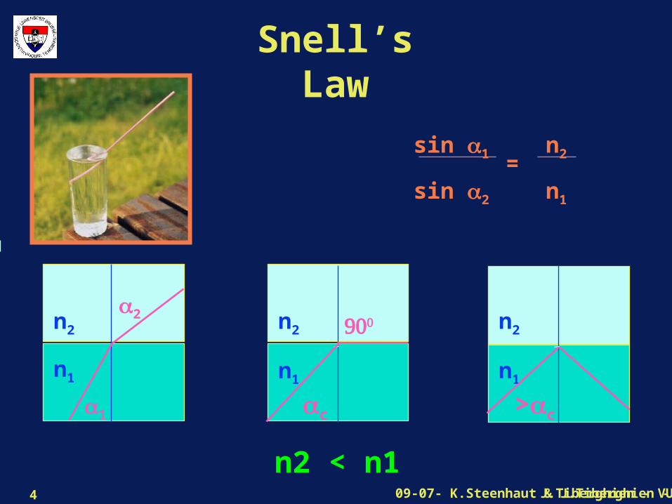
Snell’s Law
sin 1
sin 2
=n2
n1
2
1
n2
n1
c
n2
n1
>c
n2
n1
n2 < n1
J.Tiberghien - VUB09-07- K.Steenhaut & J.Tiberghien - VUB5
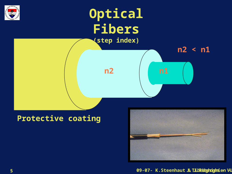
Optical Fibers(step index)
n1n2
n2 < n1
Protective coating
J.Tiberghien - VUB09-07- K.Steenhaut & J.Tiberghien - VUB6
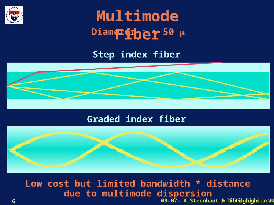
Multimode FiberDiameter : > 50
Low cost but limited bandwidth * distancedue to multimode dispersion
Step index fiber
Graded index fiber
J.Tiberghien - VUB09-07- K.Steenhaut & J.Tiberghien - VUB7
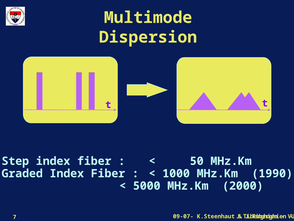
Multimode Dispersion
Step index fiber : < 50 MHz.KmGraded Index Fiber : < 1000 MHz.Km (1990)
< 5000 MHz.Km (2000)
t t

J.Tiberghien - VUB09-07- K.Steenhaut & J.Tiberghien - VUB8
Monomode Fiber
Diameter : < 5 Only one propagation mode possible
Higher cost due to end equipmentbut enormous bandwidth*distance product
10 Gb/s over 500 Km optical sections (1995)

J.Tiberghien - VUB09-07- K.Steenhaut & J.Tiberghien - VUB9
Wave Domain Multiplexing
Each color can carry an independent data flow.
In 2000
40 colors carrying each 10 Gb/s or
80 colors carrying each 2.5 Gb/s
were commercially available
J.Tiberghien - VUB09-07- K.Steenhaut & J.Tiberghien - VUB10
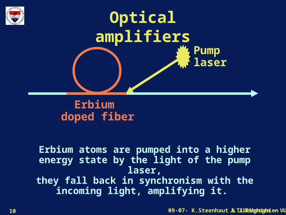
Optical amplifiers
Pumplaser
Erbium doped fiber
Erbium atoms are pumped into a higher energy state by the light of the pump laser,
they fall back in synchronism with the incoming light, amplifying it.
J.Tiberghien - VUB09-07- K.Steenhaut & J.Tiberghien - VUB11
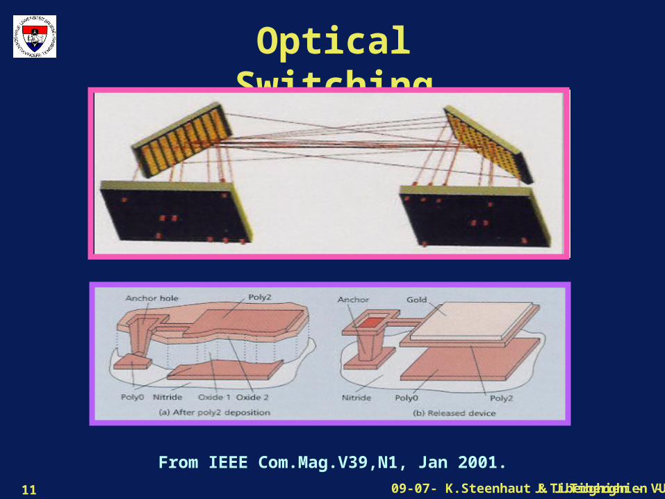
Optical Switching
From IEEE Com.Mag.V39,N1, Jan 2001.
J.Tiberghien - VUB09-07- K.Steenhaut & J.Tiberghien - VUB12
Contents
• Optical fibers
• Coaxial cables
• Twisted pairs
• Wireless communications
J.Tiberghien - VUB09-07- K.Steenhaut & J.Tiberghien - VUB13
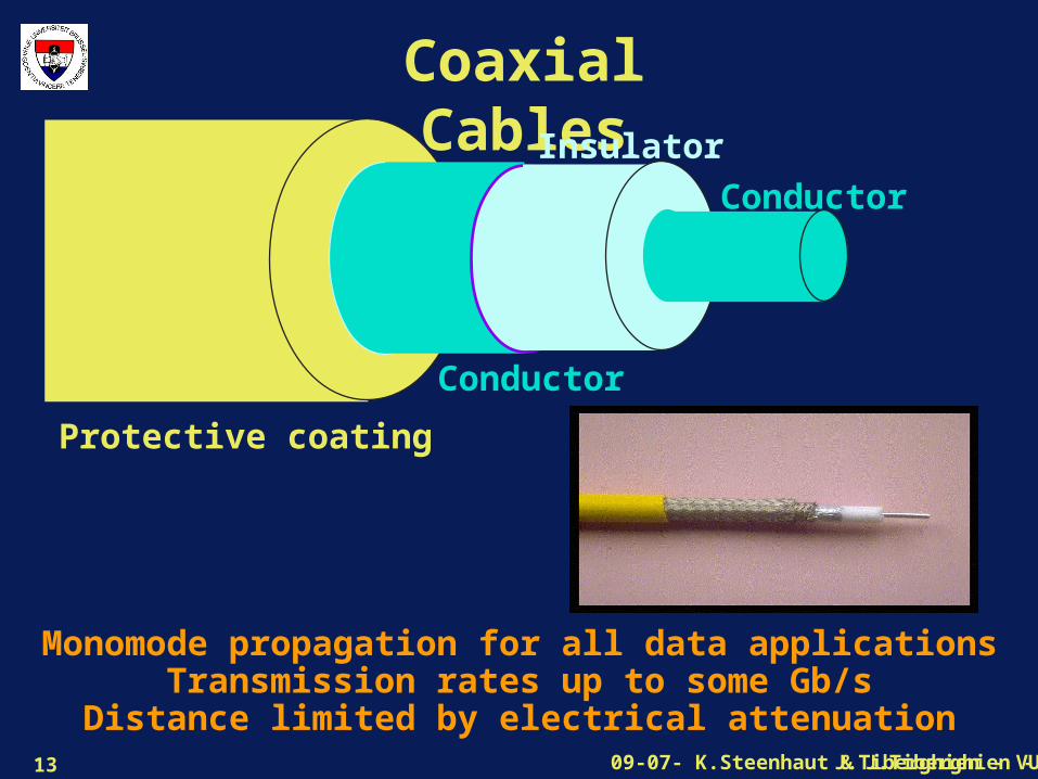
Coaxial Cables
Protective coating
Insulator
Conductor
Conductor
Monomode propagation for all data applicationsTransmission rates up to some Gb/s
Distance limited by electrical attenuation
J.Tiberghien - VUB09-07- K.Steenhaut & J.Tiberghien - VUB14
Contents
• Optical fibers
• Coaxial cables
• Twisted pairs
• Wireless communications
J.Tiberghien - VUB09-07- K.Steenhaut & J.Tiberghien - VUB15
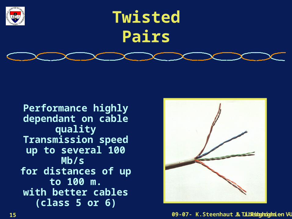
Twisted Pairs
Performance highly dependant on cable
qualityTransmission speed up
to several 100 Mb/s for distances of up to
100 m.with better cables
(class 5 or 6)
J.Tiberghien - VUB09-07- K.Steenhaut & J.Tiberghien - VUB16
Contents
• Optical fibers
• Coaxial cables
• Twisted pairs
• Wireless communications

J.Tiberghien - VUB09-07- K.Steenhaut & J.Tiberghien - VUB17
Wireless Communications
Why ?
Mobile terminals
Cost of wiring
Why Not ?
Lower data rates
Lower reliability
Potential Lack of Security
J.Tiberghien - VUB09-07- K.Steenhaut & J.Tiberghien - VUB18
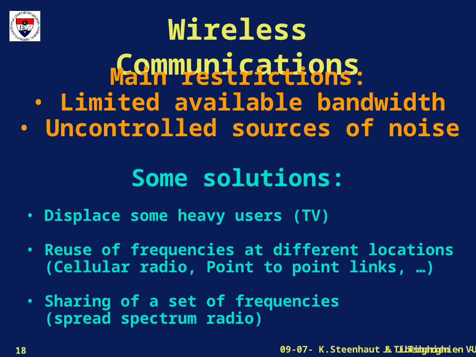
Wireless CommunicationsMain restrictions:
• Limited available bandwidth• Uncontrolled sources of noise
Some solutions:
• Displace some heavy users (TV) • Reuse of frequencies at different locations (Cellular radio, Point to point links, …)
• Sharing of a set of frequencies (spread spectrum radio)

J.Tiberghien - VUB09-07- K.Steenhaut & J.Tiberghien - VUB19
Reuse of Frequencies
Pr/Sa = Pt/r2
r
transmitter Pr = Power at receiverSa = Area of receiver antennaPt = Power at transmitterr = Distance
At some distance, a transmitter can no longer be received and the same frequency can be reused
J.Tiberghien - VUB09-07- K.Steenhaut & J.Tiberghien - VUB20
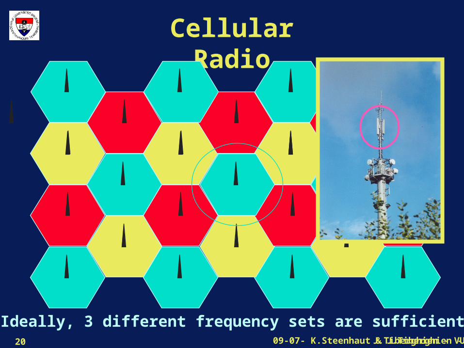
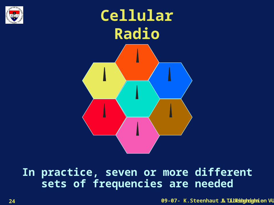
Cellular Radio
Ideally, 3 different frequency sets are sufficient
J.Tiberghien - VUB09-07- K.Steenhaut & J.Tiberghien - VUB21
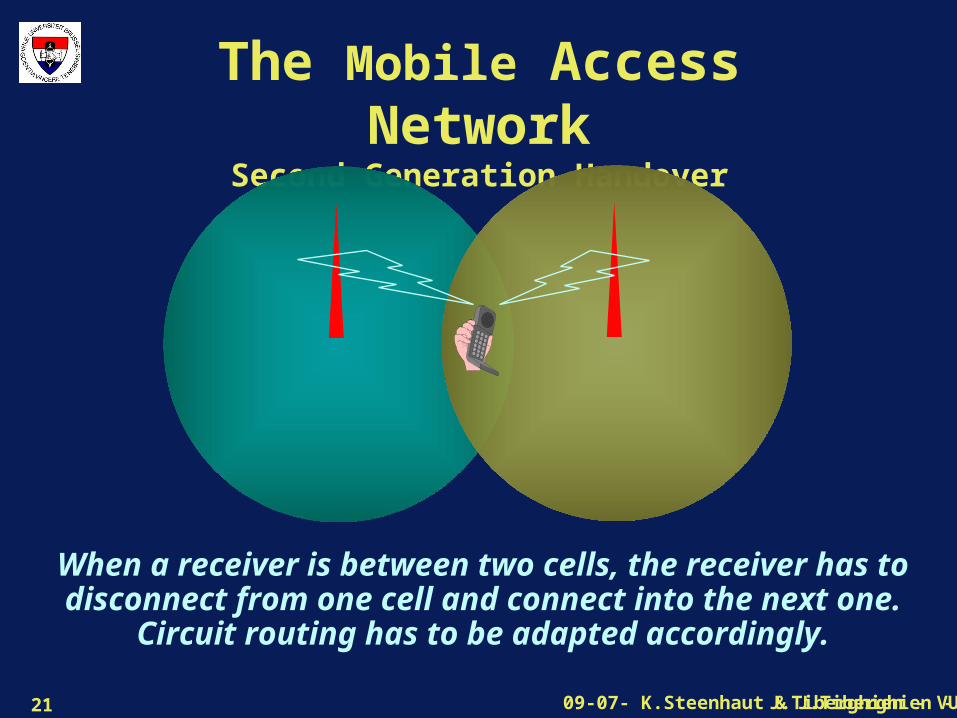
The Mobile Access NetworkSecond Generation Handover
When a receiver is between two cells, the receiver has to disconnect from one cell and connect into the next one. Circuit routing has
to be adapted accordingly.

J.Tiberghien - VUB09-07- K.Steenhaut & J.Tiberghien - VUB22
Cellular Radiok = number available frequencies per cell
S = Area of a cell = *r2
n = Number of simultaneous calls per km2
pt = Power of transmitterP0/Sa= Minimal field strength at receiver input
n = k / S
pt = p0/Sa * r2
With smaller cells, - more antenna sites are needed ...- more simultaneous calls are possible- transmitted power can be reduced
J.Tiberghien - VUB09-07- K.Steenhaut & J.Tiberghien - VUB23
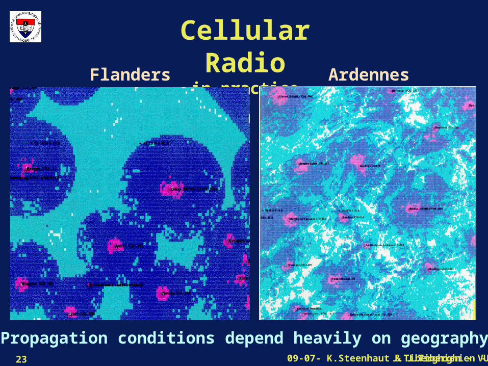
Cellular Radioin practice
Flanders Ardennes
Propagation conditions depend heavily on geography
J.Tiberghien - VUB09-07- K.Steenhaut & J.Tiberghien - VUB24
Cellular Radio
In practice, seven or more different sets of frequencies are needed
J.Tiberghien - VUB09-07- K.Steenhaut & J.Tiberghien - VUB25
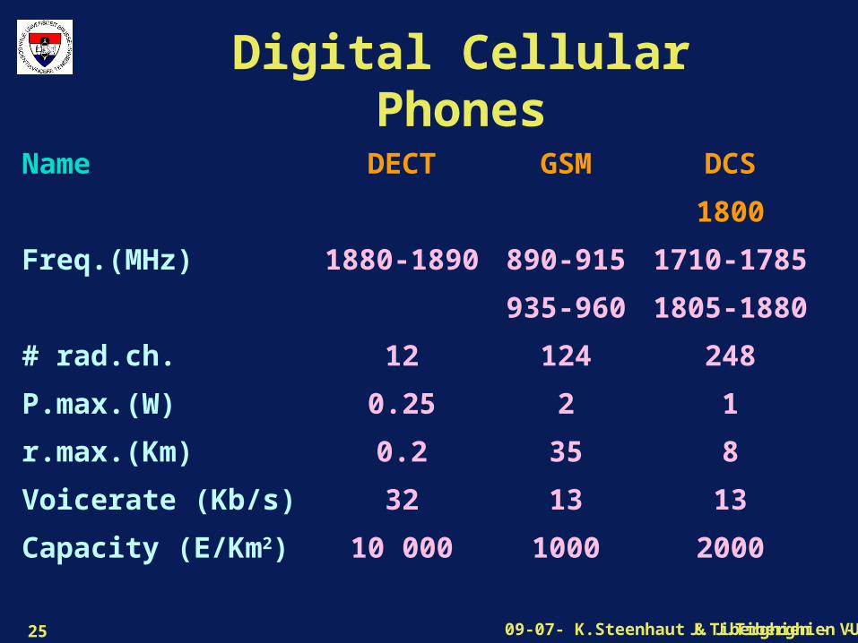
Digital Cellular Phones
Name
Freq.(MHz)
# rad.ch.
P.max.(W)
r.max.(Km)
Voicerate (Kb/s)
Capacity (E/Km2)
DECT
1880-1890
12
0.25
0.2
32
10 000
GSM
890-915
935-960
124
2
35
13
1000
DCS
1800
1710-1785
1805-1880
248
1
8
13
2000

J.Tiberghien - VUB09-07- K.Steenhaut & J.Tiberghien - VUB26
Cellular Radioand frequency
hoppingProblem :
Propagation conditions are extremely variable
in function of location and frequency,
especially in cities
Solution :
Use a set of different frequencies
and switch at a high rate between them.
e.g. In GSM every 20 mS frequencies change.

J.Tiberghien - VUB09-07- K.Steenhaut & J.Tiberghien - VUB27
Wireless CommunicationsMain restrictions:
• Limited available bandwidth• Uncontrolled sources of noise
Some solutions:
• Displace some heavy users (TV) • Reuse of frequencies at different locations (Cellular radio, Point to point links, …)
• Sharing of a set of frequencies (spread spectrum radio)

J.Tiberghien - VUB09-07- K.Steenhaut & J.Tiberghien - VUB28
Wireless Interference Margins
Cause considerable loss in transmission capacity
• Considerable room for improvements by controlling interferences
– Signal hardening
– Signal recovery
– Signal expansion
= Third generation mobile networks (UMTS)
Frequency
Space
Time
J.Tiberghien - VUB09-07- K.Steenhaut & J.Tiberghien - VUB29
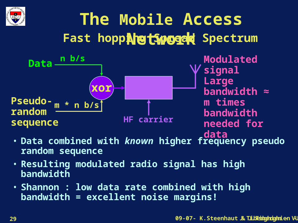
The Mobile Access Network
• Data combined with known higher frequency pseudo random sequence
• Resulting modulated radio signal has high bandwidth
• Shannon : low data rate combined with high bandwidth = excellent noise margins!
Fast hopping Spread Spectrum
n b/sData
Pseudo-random sequence
m * n b/s
xor
HF carrier
Modulated signalLarge bandwidth ≈ m times bandwidthneeded for data

J.Tiberghien - VUB09-07- K.Steenhaut & J.Tiberghien - VUB30
The Mobile Access NetworkSpread Spectrum and CDMA
D1
S1
xor
HF
Tx1
D2
S2
xor
HF
Tx2
D2
S2
HF
Correl-ator
Rx2
D1
S1
HF
Correl-ator
Rx1
For radio link Tx1-Rx1, emission by Tx2 is just another source of noise
J.Tiberghien - VUB09-07- K.Steenhaut & J.Tiberghien - VUB31
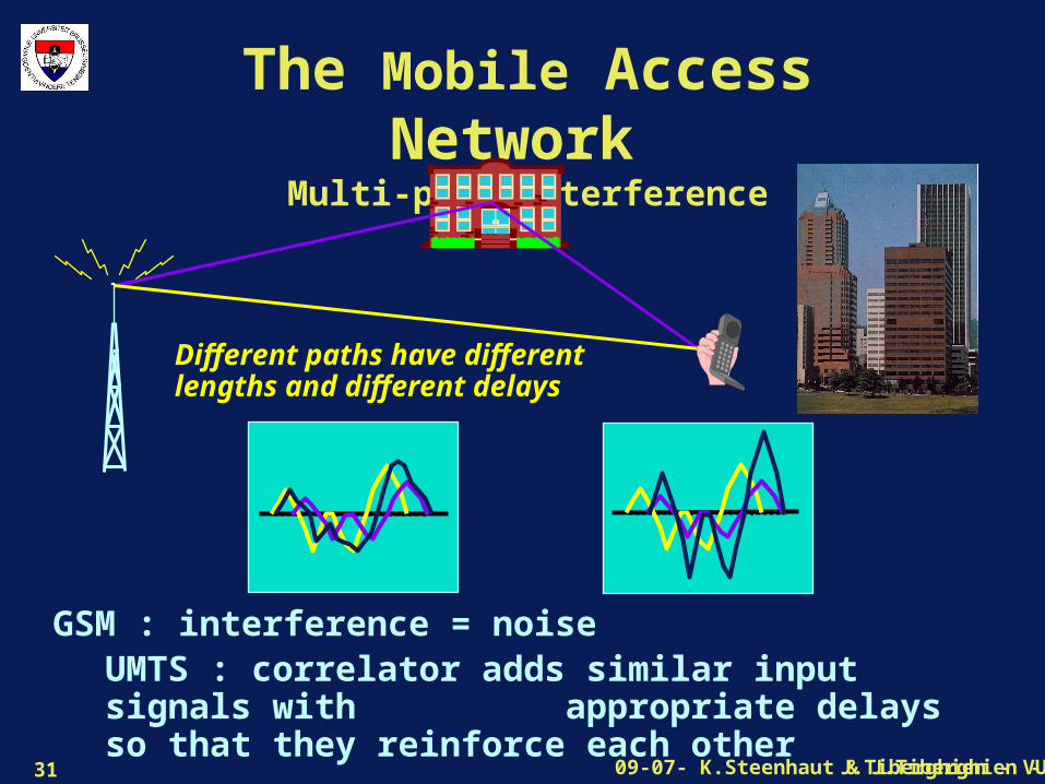
The Mobile Access Network Multi-path Interference
GSM : interference = noiseUMTS : correlator adds similar input signals with appropriate delays so that they reinforce each other
Different paths have different lengths and different delays

J.Tiberghien - VUB09-07- K.Steenhaut & J.Tiberghien - VUB32
The Mobile Access NetworkThird Generation Handover
When a receiver is between two cells, both transmitters send the same signal. These two signals reinforce each other, as multipath propagation does.
J.Tiberghien - VUB09-07- K.Steenhaut & J.Tiberghien - VUB33
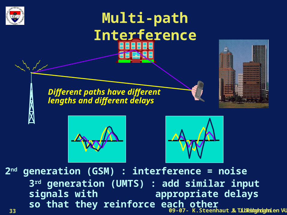
Multi-path Interference
2nd generation (GSM) : interference = noise3rd generation (UMTS) : add similar input signals with appropriate delays so that they reinforce each other
Different paths have different lengths and different delays

J.Tiberghien - VUB09-07- K.Steenhaut & J.Tiberghien - VUB34
Wireless Local Loop
Radio is sometimes cheaper than digging the streets !
Used for telephonyand forInternet access (WiMax)
J.Tiberghien - VUB09-07- K.Steenhaut & J.Tiberghien - VUB35
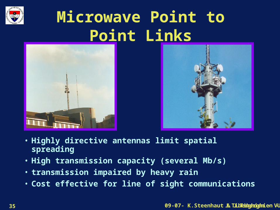
Microwave Point to Point Links
• Highly directive antennas limit spatial spreading
• High transmission capacity (several Mb/s)
• transmission impaired by heavy rain
• Cost effective for line of sight communications
J.Tiberghien - VUB09-07- K.Steenhaut & J.Tiberghien - VUB36
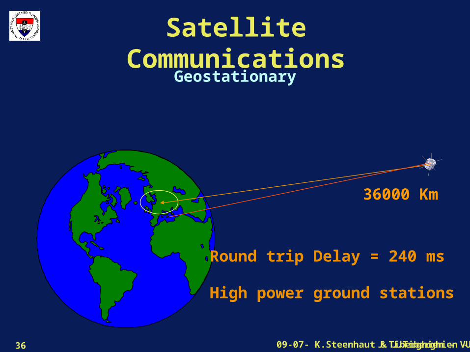
Satellite Communications
36000 Km
Geostationary
Round trip Delay = 240 ms
High power ground stations
J.Tiberghien - VUB09-07- K.Steenhaut & J.Tiberghien - VUB37
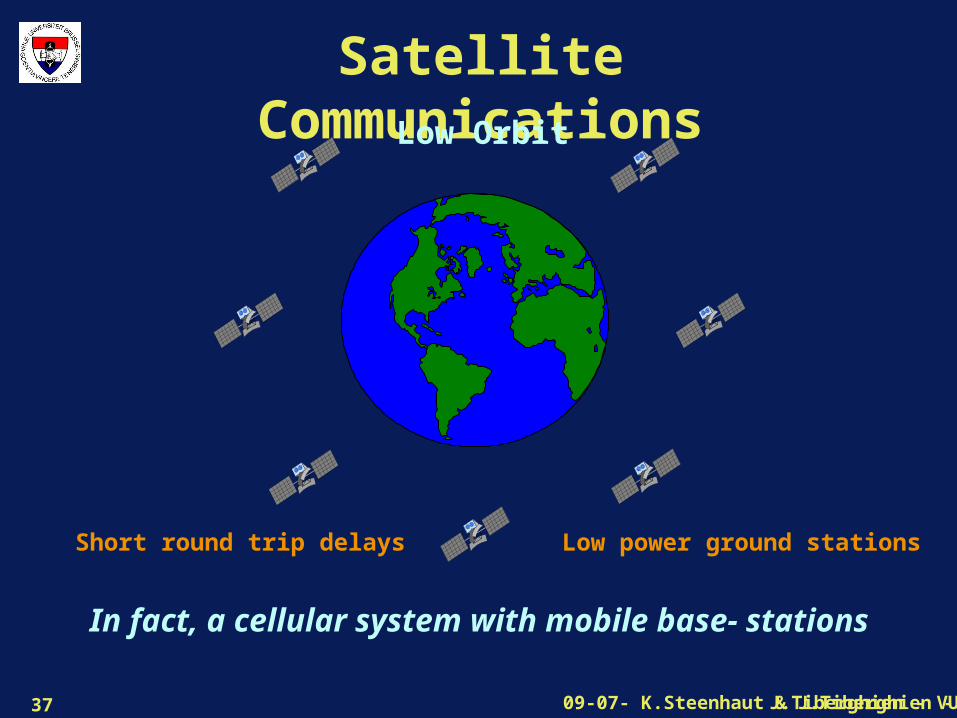
Satellite CommunicationsLow Orbit
Short round trip delays Low power ground stations
In fact, a cellular system with mobile base- stations

J.Tiberghien - VUB09-07- K.Steenhaut & J.Tiberghien - VUB38
Introduced concepts• Optical communications are becoming dominant.
– Low cost, high throughput fixed communications.
• Wireless communications are growing:
– For replacing local wiring
– For mobile communications
• Geostationary satellite communications:
–One way broadcasting
– low traffic point to point but high delays
• Low Orbit satellites:
–Cellular system for global mobile application.