Embed Size (px)
Citation preview
Journal of Theoretical and Applied Information Technology 15th October 2017. Vol.95. No 19
© 2005 – ongoing JATIT & LLS
ISSN: 1992-8645 www.jatit.org E-ISSN: 1817-3195
4922
RULES REDUCTION AND OPTIMIZATION OF FUZZY LOGIC MEMBERSHIP FUNCTIONS FOR INDUCTION
MOTOR SPEED CONTROLLER
1ZULHISYAM SALLEH, 2MARIZAN SULAIMAN, 3 FIZATUL AINI PATAKOR, 4 ROSLI OMAR
1Senior Lecturer. Dept. of Electrical Engineering, Politeknik Melaka, Plaza Pandan Malim , 75250, Melaka, Malaysia
2Professor. Faculty of Electrical Engineering, Universiti Teknikal Malaysia Melaka (UTeM) Hang Tuah Jaya, 76100 Durian Tunggal, Melaka, Malaysia
3Senior Lecturer. Dept. of Electrical Engineering Politeknik Merlimau, 77300 Melaka, Malaysia 4Associate Professor. Faculty of Electrical Engineering, Universiti Teknikal Malaysia Melaka (UTeM)
Hang Tuah Jaya, 76100 Durian Tunggal, Melaka, Malaysia
E-mail: 1 [email protected], 2 [email protected]
ABSTRACT
Fuzzy logic controllers are widely used in induction motor drives systems for their robust performance. Several techniques have been promoted to lessen the computational burden and memory constraint for implementation of fuzzy logic controller in software and hardware. Rules reduction and optimization of fuzzy logic membership functions have been tested with full, medium and low speed under forward and reverse operation of induction motor using Matlab/Simulink. The simplified fuzzy rules and membership functions were analyzed on the design and simulation of the controller for vector control induction motor. The drives system was simulated with standard membership functions through 25 rules and simplified rules such 9 rules, 7 rules and proposed 5 rules for overview comparison. The simplified rules were simulated using optimization membership functions. The results of this investigation show that Optimized5 give exceptional performance for both forward and reverse operation at rated speed with no load condition. There were less than 1% overshoot ascend for Optimized5 while tested in medium and low speed environment. These investigations confirmed that Optimize5 firmly rejected load disturbances with same short period for different speed. As a result, the consideration of optimize membership functions is significant when apply rules reduction for robust speed controller.
Keywords: Fuzzy Logic, Induction Motor, Membership Functions, Rules, Speed Controller, Optimization 1. INTRODUCTION
Nowadays, fuzzy logic controller (FLC) has shown great recognition controller because of its ability to control the plant that tough to represent mathematically due to its difficulty, nonlinearity, and inaccuracy [1]. Authors [2]and [3] suggested that Fuzzy logic controller (FLC) should be used for induction motor speed control in vector control induction motor drives. By using FLC, researchers proved that good dynamic and robustness of drives performance can be achieved[4][5].
However, the implementation of FLC in motor drives has some limitation due to high computational burden and large memory
requirement either in the hardware or software[6]. To solve this limitation and improve performance of FLC, researchers have been used several techniques such as scaling factor tuning, rule sets adaptation, and tuning membership function[1][7][8]. Some researchers proposed different techniques of reducing rules for vector control induction motor drives. The most common technique is to reduce rule set by reducing membership function (MF) numbers. Researchers often designed rule set using MF matrices to determine the output of controller based on the relationships of input or output of MFs [8]. The references[7][8][9] have studied the FLC’s with reduced the number of MF for instance 7x7, 5x5 and 3x3, and produced 49, 25 and 9 rules respectively. However, authors in [8][10] reported that reducing
Journal of Theoretical and Applied Information Technology 15th October 2017. Vol.95. No 19
© 2005 – ongoing JATIT & LLS
ISSN: 1992-8645 www.jatit.org E-ISSN: 1817-3195
4923
number of MFs and rules cause the performance of drive system differing compare to more MFs and rules. But, these contributed to less computational time and memory.
Therefore researchers in [11][12][13] are only used selected significant rules and activated in the FLC. Authors in [11] proved that by using clustering techniques enabled to reduce rule base from 64 to 16 without degrading drive performance. In addition, simplification of fuzzy rules has been implemented in [12] which only used 5 rules from 5 by 5 MFs matrices. Though, the work only considers for forward speed operation. The reduction of rules in [13] used 5x5 MF matrices and employed 7 rules due to 25 and enabled operate for wide range operation included forward and reverse speed control.
Some researchers used phase plane method to reduce rules for FLC design[1][13][14]. The useful of this method is to analyze the steadiness of nonlinear system[15]. Previous researchers have been used 49 rules and 25 rules for rules reduction and simplified until 7 rules. However, the papers were not considered to optimize the MFs for robust speed controller. Therefore, this paper investigates the successful implementation of simplified 5 rules and optimization of FLC MFs for speed
controller[16] related with full, medium and low speed under forward and reverse operation of induction motor. 5 rules are generated from reduction rules method based on 3x3 membership functions. The optimization of FLC MFs can be achieved by tuning the position of peak value of the MFs. The performances of the proposed technique were compared to 25 rules, 9 rules and 7 rules of FLC. The robustness of drives performance has been evaluated under load disturbance condition. The performance criteria, such as transient response, undershoot and recovery time due to load disturbance has been considered for performance evaluation.
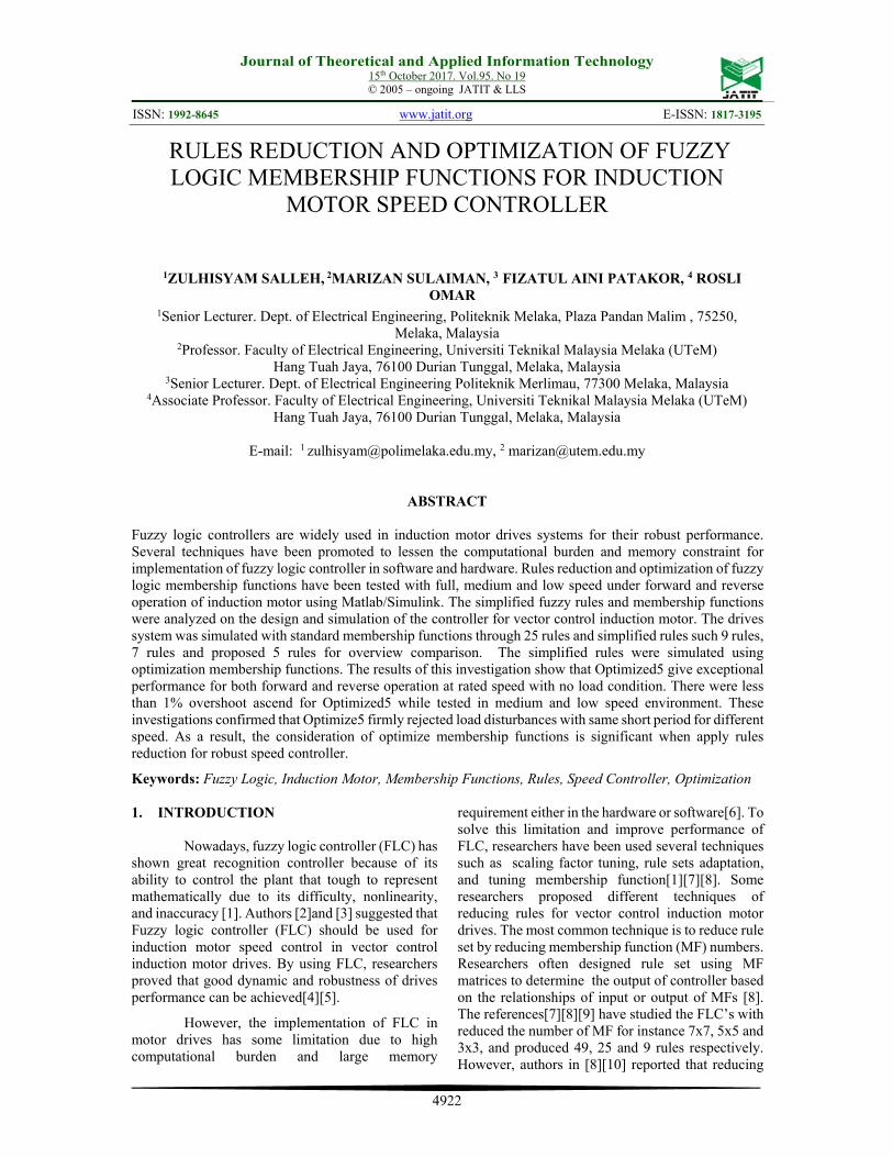
2. INDUCTION MOTOR DRIVE The illustration of the control system is
shown in Figure 1. The FLC processed the resulting error of measured rotor speed to produce q-axis reference current ∗ . The reference current ∗ and ∗ are converted through Inverse Park’s Transform to three phase form and corresponding to the current from the feedback of the motor. Then hysteresis current band received the current errors and generate switching signal for the inverter [17][18].
Figure 1: Indirect Vector Control With Hysteresis Current Band
The mathematical model of the induction
motor refer to [19] [20] can be represent as (1) –(8):
dseqs
qssqs dt
diRV
(1)
qseds
dssds dt
diRV
(2)
drreqr
qrrqr dt
diRV
)(
(3)
qrredr
drrdr dt
diRV
)(
(4)
Journal of Theoretical and Applied Information Technology 15th October 2017. Vol.95. No 19
© 2005 – ongoing JATIT & LLS
ISSN: 1992-8645 www.jatit.org E-ISSN: 1817-3195
4924
)( qrqsmqsLsqs iiLiL
(5)
)( qrqsmqrlrqr iiLiL (6)
)( drdsmdslsds iiLiL
(7)
)( drdsmdrlrdr iiLiL (8)
All different symbols in this equations denote the following: Vqs, Vds – voltages apply to the stator; ids, iqs, idr, and iqr- d and q axis stator currents and rotor currents respectively; φqs, φqr, φds, φdr - the stator and rotor flux component; Rs, Rr - the stator and rotor resistances; Lls, Llr – indicates self-inductances stator and rotor respectively, Lm - the mutual inductance. The electromagnetic torque equation of the induction motor is given by
)(22
3dsqrqsdr
r
me ii
L
LPT
(9)
P, represents the motor’s pole number. If the vector control is satisfied, the φqr would be zero. Then the electromagnetic torque is controlled only by φqs and becomes:
The rotor flux are measured using rotor time constant, rotor angular velocity and stator current as in (11).
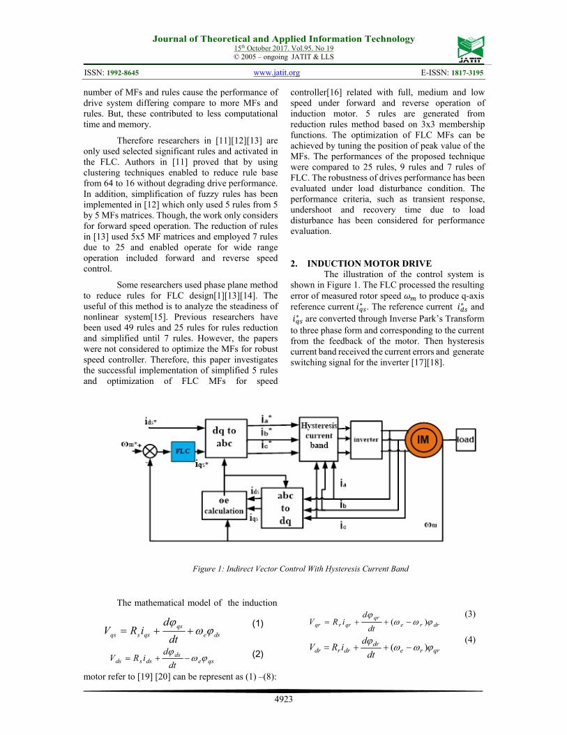
The model of simulation for vector control of induction motor is shown in Figure 2.
Figure 2: Simulation Model Of Induction Motor Drives System
3. DESIGN OF FUZZY LOGIC CONTROL
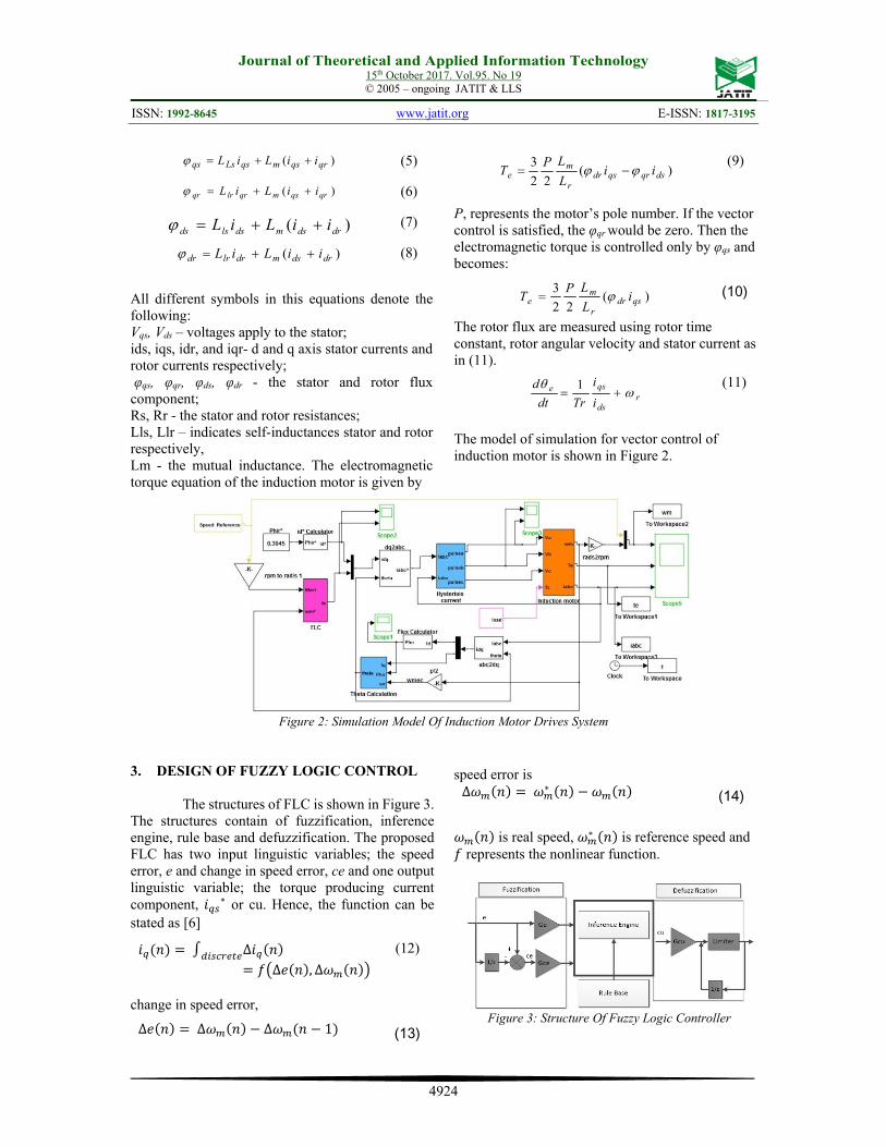
The structures of FLC is shown in Figure 3. The structures contain of fuzzification, inference engine, rule base and defuzzification. The proposed FLC has two input linguistic variables; the speed error, e and change in speed error, ce and one output linguistic variable; the torque producing current component, ∗ or cu. Hence, the function can be stated as [6]
∆∆ , ∆
(12)
change in speed error,
speed error is ∆ ∗ (14)
is real speed, ∗ is reference speed and represents the nonlinear function.
Figure 3: Structure Of Fuzzy Logic Controller
)(22
3qsdr
r
me i
L
LPT
(10)
rds
qse
i
i
Trdt
d
1
(11)
∆ ∆ ∆ 1 (13)
Journal of Theoretical and Applied Information Technology 15th October 2017. Vol.95. No 19
© 2005 – ongoing JATIT & LLS
ISSN: 1992-8645 www.jatit.org E-ISSN: 1817-3195
4925
3.1 Scaling Factors
Three scaling factors are set to fit the inputs and the output of the FLC [6]. The factors Ge and Gce
are selected to regulate the two inputs remain within the limit of -1 to +1. Factor Gcu is chosen so that one can get the rated current for rated condition. By using method in[19][8][21][22], Ge and Gce are calculated using known motor data. The motor rated speed, 184.3rad/s is assume as the maximum speed error,
of the motor. Thus, the scaling factor Ge for forward-reverse motor is determined using (15) as:
12
(15)
0.002713 The scaling factor for Gce is determined based on rated inertia and maximum torque given by manufacturer. Sampling time is 20µs.
∆
(16)
G1 1
∆
(17)
Given that ∆ 0.0964 Therefore,
G1 1
∆10.373
Gcu = 2. In order to acquire the optimum drive performances, fine tuning of the Gce is chosen because it gave more influence on the dynamic response [10]. In order to tune Gce, the coefficient of the Gce can be expressed as;
Where β denotes the tuning factor in a range 0 β 1. As a result, β= 0.2158 and from (18) Tuned Gce= 2.2385 3.2 Rule Base Design
Rule base is basically a matrices that to determine the controller output from their input(s) as it holds the input/output relationships [8]. As to provide a natural structure to convert the human data into fuzzy “IF…THEN rules, Mamdani’s type rule has been used in this work. In this stage the input variables e and ce are processed by the inference engine that implements the rule base. The linguistic
terms used for inputs and output variables are defined as: NL is Negative Large, NM is Negative Medium, NS is Negative Small, ZE is Zero Error, PS is Positive Small, PM is Positive Medium and PL is Positive Large.
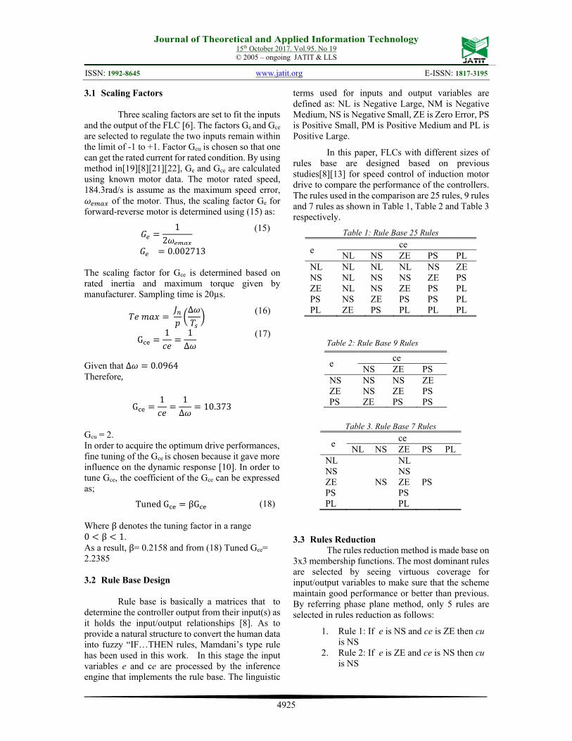
In this paper, FLCs with different sizes of rules base are designed based on previous studies[8][13] for speed control of induction motor drive to compare the performance of the controllers. The rules used in the comparison are 25 rules, 9 rules and 7 rules as shown in Table 1, Table 2 and Table 3 respectively.
Table 1: Rule Base 25 Rules
e ce NL NS ZE PS PL
NL NL NL NL NS ZE NS NL NS NS ZE PS ZE NL NS ZE PS PL PS NS ZE PS PS PL PL ZE PS PL PL PL
Table 2: Rule Base 9 Rules
e ce NS ZE PS
NS NS NS ZE ZE NS ZE PS PS ZE PS PS
Table 3. Rule Base 7 Rules
e ce NL NS ZE PS PL
NL NL NS NS ZE NS ZE PS PS PS PL PL
3.3 Rules Reduction
The rules reduction method is made base on 3x3 membership functions. The most dominant rules are selected by seeing virtuous coverage for input/output variables to make sure that the scheme maintain good performance or better than previous. By referring phase plane method, only 5 rules are selected in rules reduction as follows:
1. Rule 1: If e is NS and ce is ZE then cu is NS
2. Rule 2: If e is ZE and ce is NS then cu is NS
TunedG βG (18)
Journal of Theoretical and Applied Information Technology 15th October 2017. Vol.95. No 19
© 2005 – ongoing JATIT & LLS
ISSN: 1992-8645 www.jatit.org E-ISSN: 1817-3195
4926
3. Rule 3: If e is ZE and ce is ZE then cu is ZE
4. Rule 4: If e is ZE and ce is PS then cu is PS
5. Rule 5: If e is PS and ce is ZE then cu is PS
Therefore, NS, ZE and PS are the most important MFs to be used in the proposed design. ZE is used in change of error, ce to maintain the stabilization of the system during steady state condition. In the meantime, NS and PS are applied for the duration of transient response and cope with load. Table 4 shows 5 rules table.
\
Table 5. Rule Base 5 Rules
e ce NL NS ZE PS PL
NL NS NS ZE NS ZE PS PS PS PL
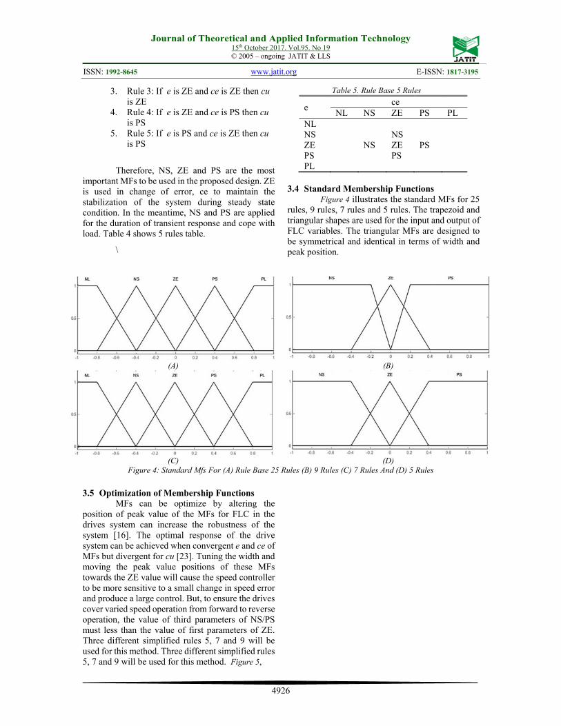
3.4 Standard Membership Functions
Figure 4 illustrates the standard MFs for 25 rules, 9 rules, 7 rules and 5 rules. The trapezoid and triangular shapes are used for the input and output of FLC variables. The triangular MFs are designed to be symmetrical and identical in terms of width and peak position.
(A) (B)
(C) (D) Figure 4: Standard Mfs For (A) Rule Base 25 Rules (B) 9 Rules (C) 7 Rules And (D) 5 Rules
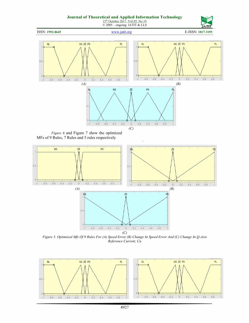
3.5 Optimization of Membership Functions
MFs can be optimize by altering the position of peak value of the MFs for FLC in the drives system can increase the robustness of the system [16]. The optimal response of the drive system can be achieved when convergent e and ce of MFs but divergent for cu [23]. Tuning the width and moving the peak value positions of these MFs towards the ZE value will cause the speed controller to be more sensitive to a small change in speed error and produce a large control. But, to ensure the drives cover varied speed operation from forward to reverse operation, the value of third parameters of NS/PS must less than the value of first parameters of ZE. Three different simplified rules 5, 7 and 9 will be used for this method. Three different simplified rules 5, 7 and 9 will be used for this method. Figure 5,
Journal of Theoretical and Applied Information Technology 15th October 2017. Vol.95. No 19
© 2005 – ongoing JATIT & LLS
ISSN: 1992-8645 www.jatit.org E-ISSN: 1817-3195
4927
Figure 6 and Figure 7 show the optimized MFs of 9 Rules, 7 Rules and 5 rules respectively
.
(A) (B)
(C) Figure 5. Optimized Mfs Of 9 Rules For (A) Speed Error (B) Change In Speed Error And (C) Change In Q-Axis
Reference Current, Cu
(A) (B)
(C)
Journal of Theoretical and Applied Information Technology 15th October 2017. Vol.95. No 19
© 2005 – ongoing JATIT & LLS
ISSN: 1992-8645 www.jatit.org E-ISSN: 1817-3195
4928
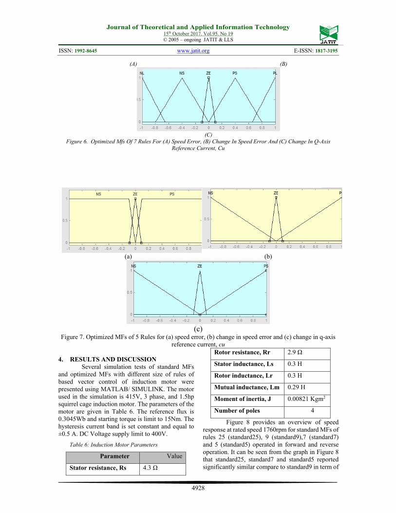
Figure 6. Optimized Mfs Of 7 Rules For (A) Speed Error, (B) Change In Speed Error And (C) Change In Q-Axis Reference Current, Cu
(a) (b)
(c) Figure 7. Optimized MFs of 5 Rules for (a) speed error, (b) change in speed error and (c) change in q-axis
reference current, cu 4. RESULTS AND DISCUSSION
Several simulation tests of standard MFs and optimized MFs with different size of rules of based vector control of induction motor were presented using MATLAB/ SIMULINK. The motor used in the simulation is 415V, 3 phase, and 1.5hp squirrel cage induction motor. The parameters of the motor are given in Table 6. The reference flux is 0.3045Wb and starting torque is limit to 15Nm. The hysteresis current band is set constant and equal to ±0.5 A. DC Voltage supply limit to 400V.
Table 6: Induction Motor Parameters
Parameter Value
Stator resistance, Rs 4.3 Ω
Rotor resistance, Rr 2.9 Ω
Stator inductance, Ls 0.3 H
Rotor inductance, Lr 0.3 H
Mutual inductance, Lm 0.29 H
Moment of inertia, J 0.00821 Kgm2
Number of poles 4
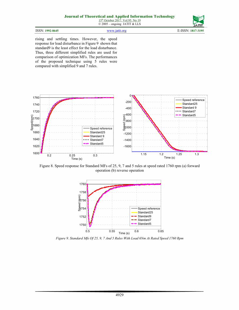
Figure 8 provides an overview of speed response at rated speed 1760rpm for standard MFs of rules 25 (standard25), 9 (standard9),7 (standard7) and 5 (standard5) operated in forward and reverse operation. It can be seen from the graph in Figure 8 that standard25, standard7 and standard5 reported significantly similar compare to standard9 in term of
(A) (B)
(C)
Journal of Theoretical and Applied Information Technology 15th October 2017. Vol.95. No 19
© 2005 – ongoing JATIT & LLS
ISSN: 1992-8645 www.jatit.org E-ISSN: 1817-3195
4929
rising and settling times. However, the speed response for load disturbance in Figure 9 shown that standard9 is the least effect for the load disturbance. Thus, three different simplified rules are used for comparison of optimization MFs. The performances of the proposed technique using 5 rules were compared with simplified 9 and 7 rules.
Figure 8. Speed response for Standard MFs of 25, 9, 7 and 5 rules at speed rated 1760 rpm (a) forward operation (b) reverse operation
Figure 9. Standard Mfs Of 25, 9, 7 And 5 Rules With Load 6Nm At Rated Speed 1760 Rpm
0.2 0.25 0.31600
1620
1640
1660
1680
1700
1720
1740
1760
Time (s)
Sp
ee
d(r
pm
)
Speed referenceStandard25Standard 9Standard7 Standard5
1.15 1.2 1.25 1.3
-1600
-1400
-1200
-1000
-800
-600
-400
-200
0
Time (s)
Sp
ee
d (
rpm
)
Speed referenceStandard25Standard 9Standard7 Standard5
0.5 0.55 0.6 0.65
1750
1752
1754
1756
1758
1760
Time (s)
Sp
ee
d (
rpm
)
Speed referenceStandard25Standard9Standard7Standard5
Journal of Theoretical and Applied Information Technology 15th October 2017. Vol.95. No 19
© 2005 – ongoing JATIT & LLS
ISSN: 1992-8645 www.jatit.org E-ISSN: 1817-3195
4930
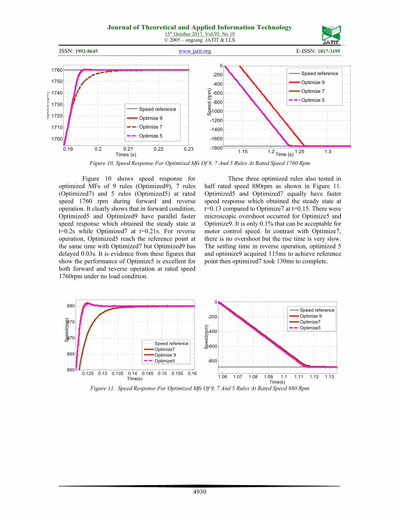
Figure 10. Speed Response For Optimized Mfs Of 9, 7 And 5 Rules At Rated Speed 1760 Rpm
Figure 10 shows speed response for optimized MFs of 9 rules (Optimized9), 7 rules (Optimized7) and 5 rules (Optimized5) at rated speed 1760 rpm during forward and reverse operation. It clearly shows that in forward condition, Optimized5 and Optimized9 have parallel faster speed response which obtained the steady state at t=0.2s while Optimized7 at t=0.21s. For reverse operation, Optimized5 reach the reference point at the same time with Optimized7 but Optimized9 has delayed 0.03s. It is evidence from these figures that show the performance of Optimize5 is excellent for both forward and reverse operation at rated speed 1760rpm under no load condition.
These three optimized rules also tested in half rated speed 880rpm as shown in Figure 11. Optimized5 and Optimized7 equally have faster speed response which obtained the steady state at t=0.13 compared to Optimize7 at t=0.15. There were microscopic overshoot occurred for Optimize5 and Optimize9. It is only 0.1% that can be acceptable for motor control speed. In contrast with Optimize7, there is no overshoot but the rise time is very slow. The settling time in reverse operation, optimized 5 and optimize9 acquired 115ms to achieve reference point then optimized7 took 130ms to complete.
Figure 11. Speed Response For Optimized Mfs Of 9, 7 And 5 Rules At Rated Speed 880 Rpm
0.19 0.2 0.21 0.22 0.23
1700
1710
1720
1730
1740
1750
1760
Times (s)
Sp
ee
d (
rpm
)
Speed reference
Optimize 9
Optimize 7
Optimize 5
1.15 1.2 1.25 1.3-1800
-1600
-1400
-1200
-1000
-800
-600
-400
-200
0
Sp
ee
d (
rpm
)
Time (s)
Speed reference
Optimize 9
Optimize 7
Optimize 5
0.125 0.13 0.135 0.14 0.145 0.15 0.155 0.16860
865
870
875
880
Time(s)
Sp
ee
d(r
pm
)
Speed referenceOptimize7Optimize 9Optimize5
1.06 1.07 1.08 1.09 1.1 1.11 1.12 1.13
-800
-600
-400
-200
0
Time(s)
Sp
ee
d(r
pm
)
Speed referenceOptimize 9Optimize7Optimize5
Journal of Theoretical and Applied Information Technology 15th October 2017. Vol.95. No 19
© 2005 – ongoing JATIT & LLS
ISSN: 1992-8645 www.jatit.org E-ISSN: 1817-3195
4931
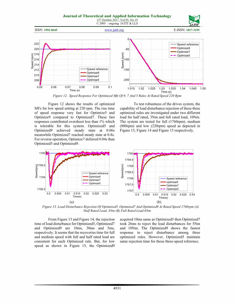
Figure 12. Speed Response For Optimized Mfs Of 9, 7 And 5 Rules At Rated Speed 220 Rpm
Figure 12 shows the results of optimized
MFs for low speed setting at 220 rpm. The rise time of speed response very fast for Optimize5 and Optimize9 compared to Optimized7. These fast responses contributed overshoot less than 1% which is tolerable for this system. Optimized5 and Optimized9 achieved steady state at 0.06s meanwhile Optimized7 reached steady state at 0.8s. For reverse operation, Optimize7 deferred 0.04s than Optimized5 and Optimized9.
To test robustness of the drives system, the capability of load disturbance rejection of these three optimized rules are investigated under two different load for half rated, 3Nm and full rated load, 10Nm. The system are tested for full (1760rpm), medium (880rpm) and low (220rpm) speed as depicted in Figure 13, Figure 14 and Figure 15 respectively.
(a) (b) Figure 13. Load Disturbance Rejection Of Optimized5, Optimized7 And Optimized9 At Rated Speed 1760rpm (A)
Half Rated Load, 3Nm (B) Full Rated Load 6Nm
From Figure 13 and Figure 14, the rejection time of load disturbance for Optimized5, Optimized7 and Optimized9 are 10ms, 30ms and 5ms, respectively. It seems that the recoveries time for full and medium speed with full and half rated load are consistent for each Optimized rule. But, for low speed as shown in Figure 15, the Optimized9
acquired 10ms same as Optimized5 then Optimized7 took 26ms to reject the load disturbances for 5Nm and 10Nm. The Optimized9 shows the fastest response to reject disturbance among three optimized rules. However, Optimized5 maintain same rejection time for those three-speed reference.
0.05 0.06 0.07 0.08 0.09 0.1
208
210
212
214
216
218
220
222
Time (s)
Sp
ee
d (
rpm
)
Speed referenceOptimize9Optimize7Optimize5
1.015 1.02 1.025 1.03 1.035 1.04 1.045 1.05
-200
-150
-100
-50
0
Time (s)
Sp
ee
d (
rpm
)
Speed referenceOptimize9Optimize7Optimize5
0.5 0.505 0.51 0.515 0.52 0.525 0.53
1758.5
1759
1759.5
1760
Time(s)
Sp
ee
d(r
pm
)
Speed referenceOptimize9Optimize7Optimize5
0.5 0.505 0.51 0.515 0.52 0.525 0.53
1757
1757.5
1758
1758.5
1759
1759.5
1760
Time(s)
Sp
ee
d(r
pm
)
Speed referenceoptimize9Optimize7Optimize5
Journal of Theoretical and Applied Information Technology 15th October 2017. Vol.95. No 19
© 2005 – ongoing JATIT & LLS
ISSN: 1992-8645 www.jatit.org E-ISSN: 1817-3195
4932
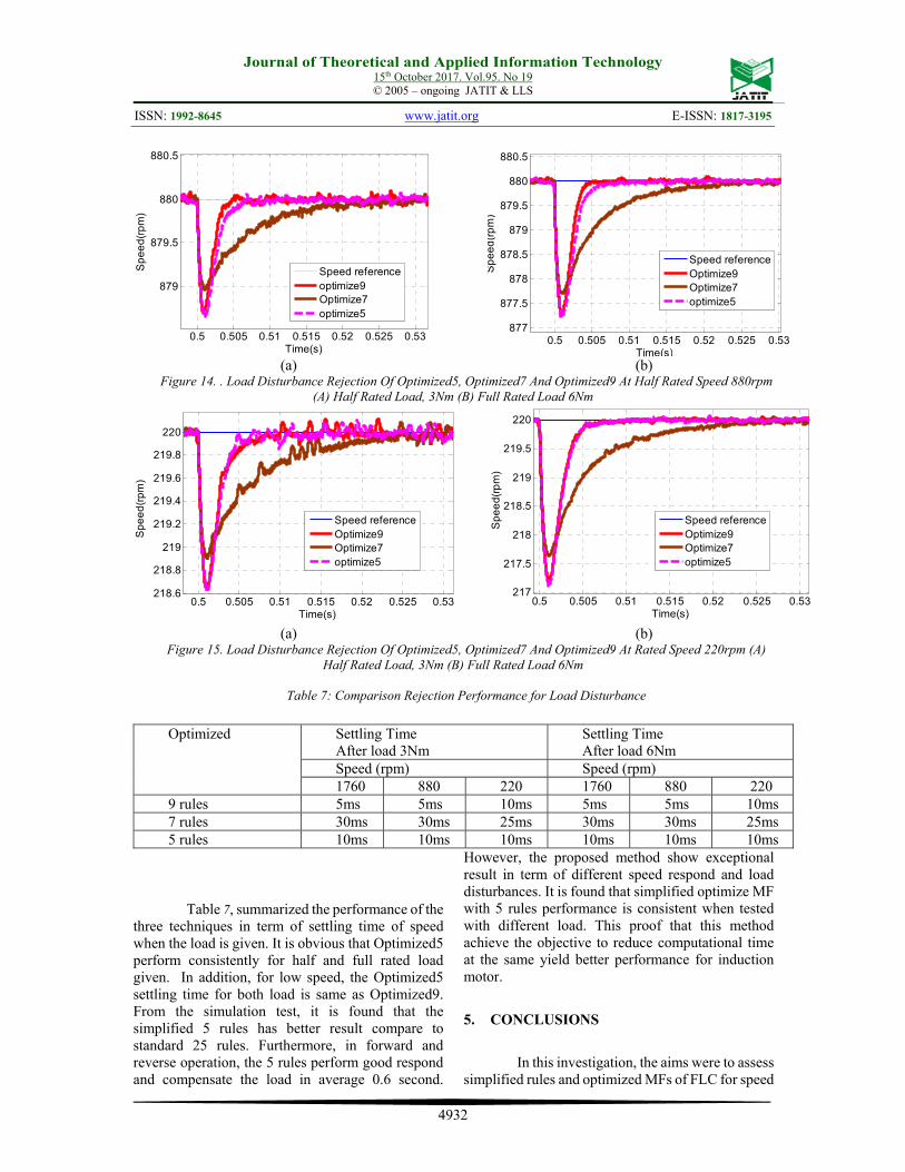
(a) (b) Figure 14. . Load Disturbance Rejection Of Optimized5, Optimized7 And Optimized9 At Half Rated Speed 880rpm
(A) Half Rated Load, 3Nm (B) Full Rated Load 6Nm
(a) (b) Figure 15. Load Disturbance Rejection Of Optimized5, Optimized7 And Optimized9 At Rated Speed 220rpm (A)
Half Rated Load, 3Nm (B) Full Rated Load 6Nm
Table 7: Comparison Rejection Performance for Load Disturbance
Table 7, summarized the performance of the three techniques in term of settling time of speed when the load is given. It is obvious that Optimized5 perform consistently for half and full rated load given. In addition, for low speed, the Optimized5 settling time for both load is same as Optimized9. From the simulation test, it is found that the simplified 5 rules has better result compare to standard 25 rules. Furthermore, in forward and reverse operation, the 5 rules perform good respond and compensate the load in average 0.6 second.
However, the proposed method show exceptional result in term of different speed respond and load disturbances. It is found that simplified optimize MF with 5 rules performance is consistent when tested with different load. This proof that this method achieve the objective to reduce computational time at the same yield better performance for induction motor.
5. CONCLUSIONS
In this investigation, the aims were to assess simplified rules and optimized MFs of FLC for speed
0.5 0.505 0.51 0.515 0.52 0.525 0.53
879
879.5
880
880.5
Time(s)
Sp
ee
d(r
pm
)
Speed referenceoptimize9Optimize7optimize5
0.5 0.505 0.51 0.515 0.52 0.525 0.53877
877.5
878
878.5
879
879.5
880
880.5
Time(s)
Sp
ee
d(r
pm
)
Speed referenceOptimize9Optimize7optimize5
0.5 0.505 0.51 0.515 0.52 0.525 0.53218.6
218.8
219
219.2
219.4
219.6
219.8
220
Time(s)
Sp
ee
d(r
pm
)
Speed referenceOptimize9Optimize7optimize5
0.5 0.505 0.51 0.515 0.52 0.525 0.53217
217.5
218
218.5
219
219.5
220
Time(s)
Sp
ee
d(r
pm
)
Speed referenceOptimize9Optimize7optimize5
Optimized Settling Time After load 3Nm
Settling Time After load 6Nm
Speed (rpm) Speed (rpm) 1760 880 220 1760 880 220
9 rules 5ms 5ms 10ms 5ms 5ms 10ms 7 rules 30ms 30ms 25ms 30ms 30ms 25ms 5 rules 10ms 10ms 10ms 10ms 10ms 10ms
Journal of Theoretical and Applied Information Technology 15th October 2017. Vol.95. No 19
© 2005 – ongoing JATIT & LLS
ISSN: 1992-8645 www.jatit.org E-ISSN: 1817-3195
4933
controller and tested in full, medium and low speed with half and full rated load under forward and reverse operation of induction motor. Thus, the performances of simplified rules and optimized rules such Optimized7 and Optimized9 were compared with proposed Optimized5. The results of this investigation show that Optimized5 give exceptional performance for both forward and reverse operation at rated speed with no load condition. The second major finding was that very small overshoot ascend for Optimized5 while tested in medium and low speed environment but the performance is acceptable compare to Optimized7 and Optimized9. These investigations confirmed that Optimize5 consistently firm in rejection of load disturbances for different speed. The result of this study indicates that optimization of FLC MFs are should be considered while apply rules reduction for robust speed controller. Further study might investigate how to fix
the overshoot by tuning the scaling factors of the motor.
6. ACKNOWLEDGEMENT
The authors would like to acknowledge the
funding given by Universiti Teknikal Malaysia Melaka (UTeM) through the grant FRGS/2/2014/TK03/FKE/01/F00238, Politeknik Merlimau and Politeknik Melaka through the grant FRGS/1/2015/TK04/JPP/03/1 and Ministry of Higher Education Malaysia for their support.
REFRENCES: [1] S.-C. Wang and Y.-H. Liu, “A Modified PI-
Like Fuzzy Logic Controller for Switched Reluctance Motor Drives,” IEEE Trans. Ind. Electron., vol. 58, no. May, pp. 1812–1825, 2011.
[2] R. Kumar, R. a. Gupta, and S. V. Bhangale, “Indirect Vector Controlled Induction Motor Drive with Fuzzy Logic Based Intelligent Controller,” in IET-UK International Conference on Information and Communication Technology in Electrical Sciences (ICTES 2007), 2007, no. Ictes, pp. 368–373.
[3] A. Kaletsanos, F. Xepapas, and S. N. Manias, “A Novel Nonlinear and Intelligent Control Technique for Induction Motor Drive Systems,” in Conference Record of the 2004 IEEE Industry Applications Conference, 2004.
39th IAS Annual Meeting., 2004, vol. 2, no. 8, pp. 1335–1341.
[4] A. Rafa, S., Larabi, A., Barazane, L., Manceur, M., Essounbouli, N., & Hamzaoui, “Fuzzy vector control of induction motor,” in In Networking, Sensing and Control (ICNSC), 2013 10th IEEE International Conference, 2013, pp. 815–820.
[5] M. Zerikat, A. Mechernene, and S. Chekroun,
“High-performance sensorless vector control of induction motor drives using artificial intelligent technique,” Eur. Trans. Electr. Power, vol. 21, no. 1, pp. 787–800, 2011.
[6] M. N. Uddin, T. S. Radwan, and M. A. Rahman, “Performances of Fuzzy-Logic-Based Indirect Vector Control for Induction Motor Drive,” IEEE Trans. Ind. Appl., vol. 38, no. 5, pp. 1219–1225, 2002.
[7] S. Chopra, R. Mitra, and V. Kumar, “Fuzzy Controller : Choosing an Appropriate and Smallest Rule Set,” Int. J. Comput. Cogn., vol. 3, no. 4, pp. 73–79, 2005.
[8] B. Kumar, Y. K. Chauhan, and V. Shrivastava, “Efficacy of Different Rule Based Fuzzy Logic Controllers for Induction Motor Drive,” Int. J. Mach. Learn. Comput., vol. 2, no. 2, pp. 131–137, 2012.
[9] J. Gayathri Monicka, D. N.O.Guna Sekhar, and K. Ramash Kumar, “Performance Evaluation of Membership Functions on Fuzzy Logic Controlled AC Voltage Controller for Speed Control of Induction Motor Drive,” Int. J. Comput. Appl., vol. 13, no. 5, pp. 8–12, 2011.
[10] S. Chopra, R. Mitra, and V. Kumar, “A robust scheme for tuning of fuzzy PI type controller,” in 3rd International IEEE Conference Intelligent Systems, September 2006, 2006, no. September, pp. 300–305.
[11] P. Vas, M. Neuroth, and A. F. Stronach, “Full fuzzy control of a DSP-based high performance induction motor drive,” in IEE Proceedings - Control Theory and Applications, 1997, vol. 144, no. 5, pp. 361–368.
[12] M. J. Hossain, M. A. Hoque, and K. K. Islam, “Simplified fuzzy control for flux-weakening speed control of IPMSM drive,” Adv. Fuzzy Syst., vol. 2011, 2011.
[13] M. H. N. Talib, Z. Ibrahim, N. A. Rahim, A. S. A. Hasim, and H. Zainuddin, “Performance Improvement of Induction Motor Drive Using Simplified FLC Method,” Power Electron. Motion Control Conf. Expo. (PEMC), 2014
Journal of Theoretical and Applied Information Technology 15th October 2017. Vol.95. No 19
© 2005 – ongoing JATIT & LLS
ISSN: 1992-8645 www.jatit.org E-ISSN: 1817-3195
4934
16th Int., no. April 2016, pp. 707–712, 2014. [14] H. Li and H. B. Gatland, “[ Z ),” IEEE Trans.
Syst. Man, Cybern. B Cybern., vol. 26, no. 5, Oct 1996, pp. 791–796, 1996.
[15] H.-X. Li and H. B. Gatland, “A New Methodology for Designing a Fuzzy Logic Controller,” IEEE Trans. Syst. Man. Cybern., vol. 25, no. 3, pp. 505–512, 1995.
[16] Z. Salleh, M. Sulaiman, and R. Omar, “Tuning
Fuzzy Membership Functions to Improve Performance of Vector Control Induction Motor Drives,” J. Telecommun. Electron. Comput. Eng., vol. 8, no. 2, pp. 1–4, 2016.
[17] F. A. Patakor, M. Sulaiman, and Z. Ibrahim, “Comparison Performance of Induction Motor Using SVPWM And Hysteresis Current Controller,” J. Theor. Appl. Inf. Technol., vol. 30, no. 1, pp. 10–17, 2011.
[18] T. H. Panchal, A. N. Patel, and S. Sonigra, “Simulation and Analysis of Indirect Field Oriented Control ( IFOC ) of Three Phase Induction Motor with Various PWM Techniques,” Int. J. New Technol. Sci. Eng., vol. 2, no. 2, pp. 76–81, 2015.
[19] M. Sulaiman, Z. Salleh, and R. Omar, “Effects of Parameters Variation in Fuzzy based Induction Motor Drives,” TELKOMNIKA Indones. J. Electr. Eng., vol. 16, no. 2, pp. 272–280, 2015.
[20] M. Sulaiman, F. Patakor, and Z. Ibrahim, “DSP based implementation of field oriented control of three-phase induction motor drives,” Int. J. Res. Eng. Technol., vol. 2, no. 9, pp. 179–186, 2013.
[21] S. N. Mat Isa, Z. Ibrahim, and F. Patkar, “Comparative study of fuzzy logic speed controller in vector controlled PMSM drive: Minimum number of fuzzy rule-base,” in 2009 Innovative Technologies in Intelligent Systems and Industrial Applications, CITISIA 2009, 2009, no. July, pp. 112–118.
[22] Z. Salleh, M. Sulaiman, R. Omar, and F. A. Patakor, “Optimization of Fuzzy Logic Based for Vector Control Induction Motor Drives,” in 2016 8th Computer Science and Electronic Engineering Conference (CEEC), 2016, pp. 1–6.
[23] B. K. Bose and L. Fellow, “Membership Function Distribution Effect on Fuzzy Logic Controlled Induction Motor Drive,” in Industrial Electronics Society, 2003. IECON’03. The 29th Annual Conference of the
IEEE, 2003, vol. 1, pp. 214–219.